basic pro - canopen implementation guide dissuade from using connectors in between the can bus line....
TRANSCRIPT

Basic PRO CanOpen Implementation
Guide
September 2011 (Ver. 2.0)

Basic Pro CanOpen Implementation Guide
Notice: • This guide is delivered subject to the following conditions and restrictions: This
guide contains proprietary information belonging to Motor power Company Srl.. Such information is supplied solely for the purpose of assisting users of the Basic Pro (1X 2X) servo drive in its installation.
• The text and graphics included in this manual are for the purpose of illustration and reference only. The specifications on which they are based are subject to change without notice.
• Motor power Company and the Motor power Company logo are trademarks of Motor power Company Srl.
• Information in this document is subject to change without notice.
Version Release Date Status Change/Remarks
Ver. 1.0 February 2011 Draft
Ver. 2.0 September 2011 BPRO-CANOPEN.PDF Official Release
2

Basic Pro CanOpen Implementation Guide
• ContentsChapter 1: Introduction .............................................................................................................6
1.1 Documentation.................................................................................................................61.2 CANopen..........................................................................................................................61.3 Cabling and pin assignment................................................................................................7
1.3.1 Cabling Hints.............................................................................................................7Chapter 2: CANopen Basics..........................................................................................................9
2.1 Physical Layer...................................................................................................................92.2 Client - Server relations.....................................................................................................92.3 Object Dictionary.............................................................................................................102.4 Communication Objects....................................................................................................10
2.4.1 Object Dictionary data types......................................................................................11Chapter 3: The Object Dictionary.................................................................................................12Chapter 4: Service data Objects SDO...........................................................................................13
4.1 Initiate SDO Download Protocol.........................................................................................134.2 Download SDO Segment Protocol.......................................................................................144.3 Initiate SDO Upload Protocol.............................................................................................154.4 Upload SDO Segment Protocol...........................................................................................164.5 Abort SDO Transfer Protocol..............................................................................................174.6 Example using SDO expedited Transfer...............................................................................19
Chapter 5: Process data Objects PDO...........................................................................................20Chapter 6: Emergency Object (EMCY)..........................................................................................21
6.1 Emergency object data.....................................................................................................21Chapter 7: Synchronization Object (SYNC)....................................................................................22Chapter 8: Network Management (NMT).......................................................................................22Chapter 9: The Bootup protocol...................................................................................................24Chapter 10: Communication Profile..............................................................................................24
10.1 Object 1000h – Device Type............................................................................................2410.2 Object 1001h – Error Register.........................................................................................2510.3 Object 1003h – Pre-defined error field..............................................................................2610.4 Object 1005h - COB-ID SYNC message.............................................................................2710.5 Object 1006h - Communication Cycle Period......................................................................2810.6 Object 1007h - Synchronous Window Length.....................................................................2810.7 Object 1008h: Manufacturer Device Name.........................................................................2910.8 Object 1009h: Manufacturer Hardware Version..................................................................3010.9 Object 100Ah: Manufacturer Software Version...................................................................3010.10 Object 1010h - Save parameters....................................................................................3110.11 Object 1011h - Restore default parameters......................................................................3210.12 Object 1014h - COB-ID Emergency Object.......................................................................3210.13 Object 1015h - Inhibit Time EMCY..................................................................................3310.14 Object 1016h - Consumer Heartbeat Time.......................................................................3310.15 Object 1017h: Producer Heartbeat Time..........................................................................3510.16 Object 1018h: Identity Object........................................................................................3510.17 Object 1029h - Error behavior .......................................................................................3710.18 Object 1200h - Server SDO Parameter............................................................................3810.19 Object 1400h:1403h - Receive PDO communication parameter .........................................4010.20 Object 1600h - 17FFh: Receive PDO Mapping Parameter....................................................4210.21 Object 1800h - 1803h: Transmit PDO Communication Parameter........................................43
10.21.1 Event time...........................................................................................................4510.21.2 Inhibit time..........................................................................................................46
10.22 Object 1A00h - 1A03h: Transmit PDO Mapping Parameter.................................................46Chapter 11: Manufacturer-specific Objects....................................................................................47
11.1 Object 2100h – Can Open Error Status Bits.......................................................................47
3

Basic Pro CanOpen Implementation Guide
11.2 Object 2F80h – Boot NMT Status......................................................................................48Chapter 12: Device Control.........................................................................................................49
12.1 General Information.......................................................................................................4912.2 State machine...............................................................................................................5112.3 Object Description.........................................................................................................56
12.3.1 Object 6040h: Controlword......................................................................................5612.3.2 Object 6041h: Statusword.......................................................................................5812.3.3 Object 6060h: Modes of operation.............................................................................6112.3.4 Object 6061h: Modes of operation display..................................................................62
Chapter 13: Profile Position Mode................................................................................................6313.1 General Information.......................................................................................................6313.2 Objects........................................................................................................................63
13.2.1 Object 607A : Target position...................................................................................6313.2.2 Object 607Bh: Position range limit............................................................................6413.2.3 Object 607Dh: Software position limit........................................................................6513.2.4 Object 6081h: Profile velocity...................................................................................6613.2.5 Object 6083h: Profile acceleration.............................................................................6613.2.6 Object 6084h: Profile deceleration.............................................................................6713.2.7 Object 6085h: Quick stop deceleration.......................................................................6813.2.8 Object 6086h: Motion profile type.............................................................................68
13.3 Functional Description....................................................................................................69Chapter 14: Homing Mode..........................................................................................................70
14.1 General information.......................................................................................................7014.2 Object description..........................................................................................................70
14.2.1 Object 607Ch: Home offset......................................................................................7014.2.2 Object 6098h: Homing method.................................................................................7114.2.3 Object 6099h: Homing speeds..................................................................................7214.2.4 Object 609Ah: Homing acceleration...........................................................................73
14.3 Functional description.....................................................................................................7414.4 Homing methods...........................................................................................................74
14.4.1 Method 1: Homing on the negative limit switch and index pulse.....................................7414.4.2 Method 2: Homing on the positive limit switch and index pulse......................................7514.4.3 Methods 3 and 4: Homing on the positive home switch and index pulse..........................7614.4.4 Methods 5 and 6: Homing on the negative home switch and index pulse.........................7614.4.5 Methods 7 to 14: Homing on the home switch and index pulse......................................7714.4.6 Methods 17 to 30: Homing without an index pulse.......................................................7914.4.7 Methods 33 to 34: Homing on the index pulse.............................................................7914.4.8 Method 35: Homing on the current position................................................................80
Chapter 15: Position control function............................................................................................8115.1 General information.......................................................................................................8115.2 Object description..........................................................................................................81
15.2.1 Object 6062h: Position demand value........................................................................8115.2.2 Object 6063h: Position actual value...........................................................................8215.2.3 Object 6064h: Position actual value...........................................................................8215.2.4 Object 6066h: Following error time out......................................................................8315.2.5 Object 6067h: Position window.................................................................................8415.2.6 Object 6068 : Position window time...........................................................................8515.2.7 Object 60F4h: Following error actual value.................................................................8515.2.8 Object 60FAh: Control effort.....................................................................................8615.2.9 Object 60FBh: Position control parameter set..............................................................86
Chapter 16: Interpolated Position Mode........................................................................................8816.1 Object description..........................................................................................................88
16.1.1 Object 60C0h: Interpolation Sub Mode Select.............................................................8816.1.2 Object 60C1h: Interpolation data record....................................................................8916.1.3 Object 60C2h: Interpolation time period....................................................................9016.1.4 Object 60C3h: Interpolation sync definition................................................................9116.1.5 Object 60C4h: Interpolation data configuration...........................................................92
4

Basic Pro CanOpen Implementation Guide
Chapter 17: Profile Velocity Mode................................................................................................9617.1 Object description..........................................................................................................96
17.1.1 Object 6069h: Velocity sensor actual value.................................................................9617.1.2 Object 606Bh: Velocity demand value........................................................................9617.1.3 Object 606Dh: Velocity window.................................................................................9717.1.4 Object 606Eh: Velocity window time..........................................................................9817.1.5 Object 606F : Velocity threshold...............................................................................9917.1.6 Object 6070h: Velocity threshold time.......................................................................9917.1.7 Object 60FFh: Target velocity.................................................................................10017.1.8 Object 60F8h: Max slippage....................................................................................10017.1.9 Object 60F9h: Velocity control parameter set............................................................101
5

Basic Pro CanOpen Implementation Guide
Chapter 1: Introduction
1.1 Documentation
This manual describes how to parametrize and control the servo positioning controller Basic Pro using the standardized protocol CANOpen. The adjustment of the physical parameters, the activation of the CANOpen protocol, the embedding into a CAN network and the communication with the controller will be explained. It is intended for persons who are already well versed with the servo positioning controller series.
For more information please consult also the others manuals of the Basic Pro servo Lines:
Basic Pro – Software Manual
Basic Pro – Installation Guide
1.2 CANopen
CANopen is a standard established by the association ”CAN in Automation ". A great number of device manufacturers are organized in this association. This standard has replaced most of all manufacturer-specific CAN protocols. So a manufacturer independent communication interface is available for the user:
CiA Draft Standard 201...207: In these standards the general network administration and the transfer of objects are determined. This book is rather comprehensive. The relevant aspects are treated in the CANopen manual in hand so that it is not necessary in general to acquire the DS201..207.
CiA Draft Standard 301: In this standard the basic structure of the object dictionary of a CANopen device and the access to this directory are described. Besides this the statements made in the DS201..207 are described in detail. The elements needed for the servo controller family Basic Pro of the object directory and the access methods which belong to them are described in the present manual. It is advisable to acquire the DS301 but not necessary.
CiA Draft Standard 402: This standard describes the concrete implementation of CANopen in servo controllers. Though all implemented objects are also briefly documented and described in this CANopen manual the user should own this book.
6

Basic Pro CanOpen Implementation Guide
Any information on CANopen protocol can be found at http://www.can-cia.de.
1.3 Cabling and pin assignment
In Basic PRO servo drive the Can Interface is already integrated in the device and therefore always available.
The Can interface is available trough the CAN/CMD connector on the front plate of the Device.
The Connector has the following pin-out:
Pin Signal Function
1 DAC1 + Analog Input Axis1
2 DAC2 + Analog Input Axis1 (Only on Dual)
3 CAN Low OUT Can Low Signal
4 CAN Gnd IN Can Gnd Signal
5 CAN High IN Can High Signal
6 DAC1,2 GND Analog Input Return
7 CAN Gnd OUT Can Gnd Signal
8 CAN High OUT Can High Signal
9 CAN Low IN Can Low Signal
Please respect carefully the following information and notes for the cabling of the controller to get a stable and undisturbed communication system. A non professional cabling can cause malfunctions of the CAN
bus which hence the controller to shut-down with an error.
1.3.1 Cabling Hints
The CAN bus offers an easy and safe way to connect all parts of a plant. As condition all following instructions have to be respected carefully.
7
Basic Pro CanOpen Implementation Guide
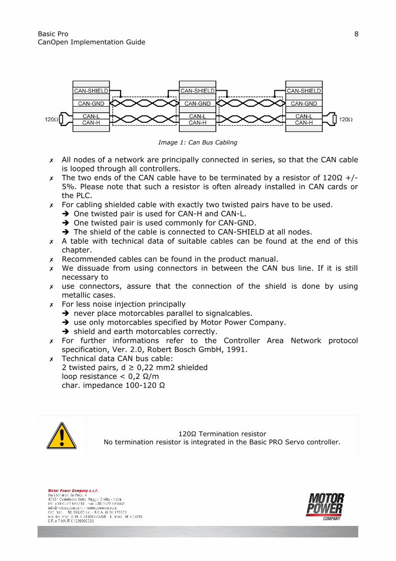
All nodes of a network are principally connected in series, so that the CAN cable is looped through all controllers.
The two ends of the CAN cable have to be terminated by a resistor of 120Ω +/- 5%. Please note that such a resistor is often already installed in CAN cards or the PLC.
For cabling shielded cable with exactly two twisted pairs have to be used. One twisted pair is used for CAN-H and CAN-L. One twisted pair is used commonly for CAN-GND. The shield of the cable is connected to CAN-SHIELD at all nodes.
A table with technical data of suitable cables can be found at the end of this chapter.
Recommended cables can be found in the product manual. We dissuade from using connectors in between the CAN bus line. If it is still
necessary to use connectors, assure that the connection of the shield is done by using
metallic cases. For less noise injection principally
never place motorcables parallel to signalcables. use only motorcables specified by Motor Power Company. shield and earth motorcables correctly.
For further informations refer to the Controller Area Network protocol specification, Ver. 2.0, Robert Bosch GmbH, 1991.
Technical data CAN bus cable:2 twisted pairs, d ≥ 0,22 mm2 shieldedloop resistance < 0,2 Ω/mchar. impedance 100-120 Ω
120Ω Termination resistorNo termination resistor is integrated in the Basic PRO Servo controller.
8
Image 1: Can Bus Cabling

Basic Pro CanOpen Implementation Guide
Chapter 2: CANopen Basics
This chapter describes — in general — the CANopen communication features most relevant to Basic PRO servo drive. More detailed information is available in the specific CANopen documentation.
2.1 Physical Layer
CAN is a serial communication standard in which the transferred data is coded as electrical pulses on a two-wire communication line. The device that handles the CAN physical layer is called the CAN controller. The device that transmits data over the CAN lines is called the CAN transceiver.
For all the information regarding the connection, please check Basic Pro Installation Guide Manual.
2.2 Client - Server relations
A CAN master (or client) is a controller that makes requests to nodes to respond to its commands. A CAN slave (or server) responds to the commands issued by the CAN master. The CAN protocol permits both single-master and multiple-master networks.The Basic Pro servo drives assume a single-master network arrangement, in which theservo drives are the slaves and the machine controller or PLC is the master.
Every servo drive has a unique ID in the range [1…127]. The network master does not require an ID. As a slave, the servo drive never sends an unrequested message, other than emergencies. The drive responds only to messages addressed to its ID or to broadcast messages, which have an ID of 0. All messages sent by a servo drive are marked with its own ID.
! If two servo drives have been assigned the same ID, the CAN network may crash.
9

Basic Pro CanOpen Implementation Guide
2.3 Object Dictionary
An object dictionary (OD) is a naming system that gives a unique identifier to each data item — or “object” —that is communicated over the CAN bus. An object is identified by an index and, if it is a complex object, also by a sub-index. A CANopen client can manipulate an object of a CANopen server by referring to its identifier, according to the access permission of the object. (An object’s access permission may be read-only, write-only, or read-write.) CiA DS 301 requires a set of mandatory objects for all CANopen devices. Other OD items are predefined by CiA DS 301 to have fixed identifiers, if supported. The OD also accommodates manufacturer-specific objects.
2.4 Communication Objects
The data-byte units transported through a CAN network are called communication objects (COBs). Basic Pro servo drive uses the following COB types:
COB Type Description
Network Management (NMT) NMT objects are used by CAN clients to initialize a servo drive as a server.
Emergency (EMCY)
Emergency messages are used by the servo drives to warn of an exception. The EMCY is the only COB type that a servo drive may transmit without first being explicitly asked. EMCY objects are similar to servo drive “interrupts”: they eliminate the need to poll the servo drive continuously for the emergency status.
Process data object (PDO)
PDO messages are used to manipulate OD objects without explicit reference to the object identifier, which is possible if there is an a-priori convention concerning the OD item referenced. Such conventions are called “PDO mappings”; these are actually OD objects themselves, and may be defined and manipulated using an SDO.
Service data object (SDO)
SDO messages are used to manipulate OD objects according to their IDs. The server receives the SDO, which specifies in its message which object is to be dealt with. SDO messages can be chained to form a “domain transfer,” which is useful for sending large data items such as long strings. Domain transfers are time-consuming, because the CAN bus is half-duplex. Each time a data segment is downloaded, a full-sized data segment is uploaded for verification, and vice versa.
Table 1: Comunication Object used by Basic Pro
10

Basic Pro CanOpen Implementation Guide
The type of COB transmitted is indicated in the arbitration field of the message, and thereby determines its priority. The relation between bits 8 to 11 of the arbitration field (COB-ID) and the COB type is presented in the following table:
COB Type Bits 8-11 COB-ID ID Range
NMT 0000 0
SYNC 0001 128 (80h)
Time Stamp 0010 256 (100h)
Emergency 0001 129 .. 255 (81h .. 255h)
PDO1 – Transmit 0011 513 .. 639 (181h .. 1FFh)
PDO1 – Receive 0100 641 .. 767 (281h .. 2FFh)
PDO2 – Transmit 0101 897 .. 1023 (381h .. 3FFh)
PDO2 – Receive 0110
PDO3 – Transmit 0111
PDO3 – Receive 1000
PDO4 – Transmit 1001
PDO4 – Receive 1010
SDO – Transmit 1011
SDO – Receive 1100
Error control (node guarding) 1110 1739 .. 1919 (701h .. 77FFh)
2.4.1 Object Dictionary data types
The Basic PRO CAN controller supports the following data types:
Index Object Name
0002 DEFTYPE Integer8
0003 DEFTYPE Integer16
0004 DEFTYPE Integer32
0005 DEFTYPE Unsigned8
0006 DEFTYPE Unsigned16
0007 DEFTYPE Unsigned32
0008 DEFTYPE Floating Point(Float)
0009 DEFTYPE Visible String
0020 DEFSTRUCT PDO communication parameter
11

Basic Pro CanOpen Implementation Guide
0021 DEFSTRUCT PDO Mapping
0023 DEFSTRUCT Identity
0081 DEFTYPE DSP 402 Interpolated data record
Data Objects 0002 to 0004 are used as map able “dummy” entries.
Chapter 3: The Object Dictionary
The most important part of a device profile is the Object Dictionary description. The Object Dictionary is essentially a grouping of objects accessible via the network in an ordered pre-defined fashion. Each object within the dictionary is addressed using a 16-bit index.The overall layout of the standard Object Dictionary is shown below. This layout closely conforms with other industrial serial bus system concepts:
Index (hex) Object
0000 Not used
0001-001F Static data types
0020-003F Complex data types
0040-005F Manufacturer specific Complex data types
0060-007F Device Profile Specific Static Data Types
0080-009F Device Profile Specific Complex Data Types
00A0-0FFF Reserved for further us
1000-1FFF Communication Profile Area
2000-5FFF Manufacturer Specific Profile Area
6000-9FFF Standardized Device Profile Area
A000-FFFF Reserved for further use
The Object Dictionary may contain a maximum of 65536 entries which are addressed through a 16-bit index.
12

Basic Pro CanOpen Implementation Guide
Chapter 4: Service data Objects SDO
Basic PRO digital servo drives use a single transmit server SDO (COB 581h-6ffh) and a single receive server SDO (COB601h-67fh). This is according to CiA definitions and priority allocations for 11-bit addressing.
When using SDOs, it is important to remember that:• An SDO has a lower priority than a PDO.• An SDO session is not complete until it is confirmed.
For example, if an SDO is used to change a PDO mapping, the SDO should be issued only after the last session in which the PDO is completed, and the newly-mapped PDO should not be used until the SDO mapping change is confirmed.
4.1 Initiate SDO Download Protocol
This protocol is used to implement the Initiate SDO Download service for SDOs.
Client to server:
Byte 0 Byte 1 – 3 Byte 4 - 7
7..5 4 3..2 1 0 - -
css=1 x n e s m d (data)
Server to client:
Byte 0 Byte 1 – 3 Byte 4 - 7
7..5 4..0 - -
scs=3 x m reserved
Where:
css Client command specifier1: Initiate download request
scs Server command specifier3: Initiate download response
n Number of bytes in d that do not contain data. Only valid if e = 1 and s = 1; otherwise it is 0. Bytes [8-n, 7] do not contain data.
e Transfer type 0: Normal transfer
13

Basic Pro CanOpen Implementation Guide
1: Expedited transfer
s Size indicator 0: Data set size is not indicated 1: Data set size is indicated
m Multiplexor. Represents index/sub-index of data to be transferred by SDO.
d Data e = 0, s = 0: d is reserved for future use.e = 0, s = 1: d contains number of bytes to be downloaded.Byte 4 contains LSB and byte 7 contains MSB.e = 1, s = 1: d contains data of length 4-n to be downloaded. The encoding depends on the type of data referenced by index and sub-index.e = 1, s = 0: d contains an unspecified number of bytes to be downloaded.
x Not used; always 0.
reserved Reserved for future use; always 0.
4.2 Download SDO Segment Protocol
This protocol is used to implement the Download SDO Segment service.
Client to server:
Byte 0 Byte 1 – 7
7..5 4 3..1 0 -
css=0 t n c Segment - data
Server to client:
Byte 0 Byte 1 – 7
7..5 4 3..0 -
css=1 t x reserved
Where:
ccs: client command specifier0: download segment request
14

Basic Pro CanOpen Implementation Guide
scs: server command specifier1: download segment response
seg-data: at most 7 bytes of segment data to be downloaded. The encoding depends on the type of the data referenced by index and sub-index
n: indicates the number of bytes in seg-data that do not contain segment data. Bytes [8-n, 7] do not contain segment data. n = 0 if no segment size is indicated.
c: indicates whether there are still more segments to be downloaded.0 more segments to be downloaded1: no more segments to be downloaded
t: toggle bit. This bit must alternate for each subsequent segment that is downloaded. The firstnsegment will have the toggle-bit set to 0. The toggle bit will be equal for the request and the response message.
x: not used, always 0
reserved: reserved for further use, always 0
4.3 Initiate SDO Upload Protocol
This protocol is used to implement the Initiate SDO Upload service.
Client to server:
Byte 0 Byte 1 – 3 Byte 4 – 7
7..5 4..0 - -
css=2 x m reserved
Server to client:
Byte 0 Byte 1 – 3 Byte 4 - 7
7..5 4 3..2 1 0 - -
css=2 x n e s m d (data)
Where:
ccs: client command specifier2: initiate upload request
15

Basic Pro CanOpen Implementation Guide
scs: server command specifier2: initiate upload response
n: Only valid if e = 1 and s = 1, otherwise 0. If valid it indicates the number of bytes in d that do not contain data. Bytes [8-n, 7] do not contain segment data.
e: transfer type0: normal transfer1: expedited transfer
s: size indicator0: data set size is not indicated1: data set size is indicated
m: multiplexor. It represents the index/sub-index of the data to be transfer by the SDO.
d: datae = 0, s = 0: d is reserved for further use.e = 0, s = 1: d contains the number of bytes to be uploaded.Byte 4 contains the lsb and byte 7 contains the msb.e = 1, s = 1: d contains the data of length 4-n to be uploaded,the encoding depends on the type of the data referenced by index and sub-index e = 1, s = 0: d contains unspecified number of bytes to be uploaded.
x: not used, always 0
reserved: reserved for further use , always 0
4.4 Upload SDO Segment Protocol
This protocol is used to implement the Upload SDO Segment service.
Client to server:
Byte 0 Byte 1 – 7
7..5 4 3..0 -
css=2 t x reserved
Server to client:
16

Basic Pro CanOpen Implementation Guide
Byte 0 Byte 1 – 7
7..5 4 3..1 0 -
css=0 t n c Segment - data
Where:
ccs: client command specifier3: upload segment request
scs: server command specifier0: upload segment response
t: toggle bit. This bit must alternate for each subsequent segment that is uploaded. The first segment will have the toggle-bit set to 0. The toggle bit will be equal for the request and the response message.
c: indicates whether there are still more segments to be uploaded.0: more segments to be uploaded1: no more segments to be uploaded
seg-data: at most 7 bytes of segment data to be uploaded. The encoding depends on the type of the data referenced by index and sub-index
n: indicates the number of bytes in seg-data that do not contain segment data. Bytes [8-n, 7] do not contain segment data. n = 0 if no segment size is indicated.
x: not used, always 0
reserved: reserved for further use, always 0
4.5 Abort SDO Transfer Protocol
This protocol is used to implement the Abort SDO Transfer Service.
Client to server:
Byte 0 Byte 1 – 3 Byte 4 – 7
7..5 4..0 - -
cs=4 x m d (data)
Where:
17

Basic Pro CanOpen Implementation Guide
cs: command specifier4: abort transfer request
x: not used, always 0
m: multiplexor. It represents index and sub-index of the SDO.
d: contains a 4 byte abort code about the reason for the abort.
the abort code is encoded as UNSIGNED32 value.
Abort Code Description
0503 0000h Toggle bit not alternated.
0504 0000h SDO protocol timed out.
0504 0001h Client/server command specifier not valid or unknown.
0504 0002h Invalid block size (block mode only).
0504 0003h Invalid sequence number (block mode only).
0504 0004h CRC error (block mode only)
0504 0005h Out of memory.
0601 0000h Unsupported access to an object.
0601 0001h Attempt to read a write only object.
0601 0002h Attempt to write a read only object.
0602 0000h Object does not exist in the object dictionary.
0604 0041h Object cannot be mapped to the PDO.
0604 0042h The number and length of the objects to be mapped would exceed PDO length.
0604 0043h General parameter incompatibility reason.
0604 0047h General internal incompatibility in the device.
0606 0000h Access failed due to an hardware error.
0607 0010h Data type does not match, length of service parameter does not match
0607 0012h Data type does not match, length of service parameter too high
0607 0013h Data type does not match, length of service parameter too low
0609 0011h Sub-index does not exist.
0609 0030h Value range of parameter exceeded (only for write access).
0609 0031h Value of parameter written too high.
0609 0032h Value of parameter written too low.
0609 0036h Maximum value is less than minimum value.
0800 0000h general error
18

Basic Pro CanOpen Implementation Guide
0800 0020h Data cannot be transferred or stored to the application.
0800 0021h Data cannot be transferred or stored to the application because of local control.
0800 0022h Data cannot be transferred or stored to the application because of thepresent device state.
0800 0023h Object dictionary dynamic generation fails or no object dictionary ispresent (e.g. object dictionary is generated from file and generation fails because of an file error).
The abort codes not listed here are reserved.
4.6 Example using SDO expedited Transfer
Here below some sample for reading and writing different objects:
UINT8/INT8
Reading Object: 6061-00hReturning data: 01h
Command: 40h 61h 60h 00h
Answer: 4Fh 61h 60h 00h 01h
Writing Object: 1401-02hData: EFh
Command: 2Fh 01h 14h 02h EFh
Answer: 60h 01h 14h 02h
UINT16/INT16
Reading Object: 6041-00hReturning data: 1234h
Command: 40h 41h 60h 00h
Answer: 4Bh 41h 60h 00h 34h 12h
Writing Object: 6040-00hData: 03E8h
Command: 2Bh 40h 60h 00h E8h 03h
Answer: 60h 01h 60h 00h
19

Basic Pro CanOpen Implementation Guide
UINT32/INT32
Reading Object: 6093-01hReturning data: 12345678h
Command: 40h 93h 60h 01h
Answer: 43h 93h 60h 01h 78h 56h 34h 12h
Writing Object: 6093-01hData: 12345678h
Command: 23h 93h 60h 01h 78h 56h 34h 12h
Answer: 60h 93h 60h 01h
Always wait for the acknowledge of the controller!Only if a request has been acknowledged by the controller it is allowed to send the next request.
20

Basic Pro CanOpen Implementation Guide
Chapter 5: Process data Objects PDO
Process Data Objects (PDOs) are suitable to transmit data event-controlled, whereat the PDO contains one or more predefined parameters. In contrast to SDOs no hand-shake is used. So the receiver has to be able to handle an arriving PDO at any time. In most cases this requires a great deal of software in the host computer. This disadvantage is in contrast to the advantage that the host computer does not need cyclically inquiry of the objects embedded in a PDO, which means a strong reduction of bus load.
Following types of PDO can be used:
Transmit PDO (TPDO) Basic PRO Host→Servo controller sends PDO if
a certain event occurs
Receive PDO (RPDO) Host Basic PRO →Servo controller evaluates
PDO if a certain event occurs
The servo controller disposes of four Transmit- and four Receive-PDOs.Almost all parameters can be embedded (mapped) into a PDO, i.e. the PDO is for example composed of the velocity actual value, the position actual value or the like.
21

Basic Pro CanOpen Implementation Guide
Chapter 6: Emergency Object (EMCY)
Emergency objects are triggered by the occurrence of a device internal error situation and are transmitted from an emergency producer on the device. Emergency objects are suitable for interrupt type error alerts. An emergency object is transmitted only once per 'error event'. As long as no new errors occur on a device no further emergency objects must be transmitted.
The emergency object may be received by zero or more emergency consumers. The reaction on the emergency consumer(s) is not specified and does not fall in the scope of this document.
By means of this specification emergency error codes and the error register are specified.
6.1 Emergency object data
The Emergency Telegram consists of 8 bytes with the data as shown below.
22

Basic Pro CanOpen Implementation Guide
Chapter 7: Synchronization Object (SYNC)
The Synchronization Object is broadcasted periodically by the SYNC producer. This SYNC provides the basic network clock. The time period between the SYNCs is specified by the standard parameter communication cycle period (see Object 1006h: Communication Cycle Period), which may be written by a configuration tool to the application devices during the boot-up process. There can be a time jitter in transmission by the SYNC producer corresponding approximately to the latency due tosome other message being transmitted just before the SYNC.In order to guarantee timely access to the CAN bus the SYNC is given a very high priority identifier (1005h).
COB-ID=0080h NO DATA
Chapter 8: Network Management (NMT)
NMT commands are used to control the communication state of the servo drive and to broadcast manufacturer messages to all other connected servo drives.
The NMT message contains only 2 data byte, with the following format:
COB-ID=0000h NMT-command node-id
The following network communication states are supported, with the following communication type.
23

Basic Pro CanOpen Implementation Guide
State Description SDO PDO NMT SYNC
InizializationServo drive is not ready, or it is booting. Drive will not respond to communication and will not transmit anything.
- - - -
Pre-operational
Servo drive boot sequence is complete, but no command has been received to enter operational mode. The servo drive will respond to SDO and NMT messages, but not to PDOs.
X - X X
OperationalServo drive is fully operational, responding to PDO, SDO and NMT messages.
X X X X
Stopped Servo drive can respond only to NMT objects (including heartbeats). - - X -
Tabella 2: Network Management
Here below we can find the NMT state machine with all the allowed transitions.
The transition (2) from Initialization state to Pre-Operational state is done automatically by the servo.
The following NMT commands are supported:
Command Specifier Service
24
Image 2: State diagram

Basic Pro CanOpen Implementation Guide
1 (01h) Start Remote Node (3)(6)
2 (02h) Stop Remote Node (8)(5)
128 (80h) Enter Pre-Operational state (4)(7)
129 (81h) Reset node (12)(13)(14)
130 (82h) Reset communication (9)(10)(11)
Chapter 9: The Bootup protocol
This protocol is used to signal that an NMT slave has entered the pre-operational node state after the initializing state. The protocol uses the same identifier as the error control protocols.
COB-ID=1792+node-id 0
Only one byte with 0 (zero) value is transmitted.
Chapter 10: Communication Profile
This chapter define all the Basic PRO object available in the communication profile area of the Object Dictionary.
10.1 Object 1000h – Device Type
This object contains information about the device type and functionality. It is comprised of a 16-bit field that describes the device profile used, and a second 16-bit field that gives additional information about optional functionality of the device.
MSB LSB
BYTE 4 BYTE 3 BYTE 2 BYTE 1
Additional Information Device profile Number
25

Basic Pro CanOpen Implementation Guide
Object Description:
Index 1000h
Name Device type
Object code VAR
Data Type UNSIGNED32
Category Mandatory
Entry Description:
Access Read Only
PDO Mapping NO
Value Range UNSIGNED32
Default Value 0x191
10.2 Object 1001h – Error Register
This object is an error register for the device.
Object Description:
Index 1001h
Name Error Register
Object code VAR
Data Type UNSIGNED8
Category Mandatory
Entry Description:
Access Read Only
PDO Mapping NO
Value Range UNSIGNED8
Default Value 0x0
26

Basic Pro CanOpen Implementation Guide
Data description:
bit Meaning
0 Generic Error
1 Current
2 Voltage
3 Temperature
4 Communication Error
5 Device Profile Specific
6 Reserved
7 Manufacturer Specific
If a bit is set to 1, the specified error has occurred.
10.3 Object 1003h – Pre-defined error field
The object at index 1003h holds the errors that have occurred on the device and have been signaled via the Emergency Object. In doing so it provides an error history.
1. The entry at sub-index 0 contains the number of actual errors that are recorded in the array starting at sub-index 1.
2. Every new error is stored at sub-index 1, the older ones move down the list.3. Writing a „0“ to sub-index 0 deletes the entire error history (empties the array).4. The error numbers are of type UNSIGNED32 and are composed of a 16 bit
error code and a 16 bit additional error information field which is manufacturer specific. The error code is contained in the lower 2 bytes (LSB) and the additional information is included in the upper 2 bytes (MSB). The Error list contain 8 elements.
MSB LSB
BYTE 4 BYTE 3 BYTE 2 BYTE 1
Additional Information Error Code
Object Description:
Index 1003h
Name Pre-defined error field
27

Basic Pro CanOpen Implementation Guide
Object code ARRAY
Data Type UNSIGNED32
Category Optional
Entry Description:
Sub-Index 0
Description Number of actual error
Entry Category Mandatory
Access Read/Write
PDO Mapping NO
Value Range UNSIGNED32
Default Value 0x0
Sub-Index 01 - 08
Description Standard Error Field
Entry Category Mandatory
Access Read
PDO Mapping NO
Value Range UNSIGNED32
Default Value 0x0
10.4 Object 1005h - COB-ID SYNC message
This object defines the COB-ID of the synchronization object (SYNC).
MSB LSB
31 30 29 28-11 10-0
x 0 0 0 11-bit identifier
Object Description:
Index 1005h
Name COB-ID SYNC message
Object code VAR
28

Basic Pro CanOpen Implementation Guide
Data Type UNSIGNED32
Category Mandatory
Entry Description:
Access Read/Write
PDO Mapping NO
Value Range UNSIGNED32
Default Value 0x80
10.5 Object 1006h - Communication Cycle Period
This object defines the communication cycle period in µs. This period defines the SYNC interval. It is 0 if not used. If the communication cycle period on sync producer is changed to a new value unequal 0 the transmission of sync object resumes within 1 sync cycle of the new value.
Object Description:
Index 1006h
Name Communication Cycle Period
Object code VAR
Data Type UNSIGNED32
Category Conditional; Mandatory for sync producers
Entry Description:
Access Read/Write
PDO Mapping NO
Value Range UNSIGNED32
Default Value 0x0
10.6 Object 1007h - Synchronous Window Length
Contains the length of the time window for synchronous PDOs in ms. It is 0 if not used.
29

Basic Pro CanOpen Implementation Guide
Object Description:
Index 1007h
Name Communication Cycle Period
Object code VAR
Data Type UNSIGNED32
Category Optional
Entry Description:
Access Read/Write
PDO Mapping NO
Value Range UNSIGNED32
Default Value 0x0
10.7 Object 1008h: Manufacturer Device Name
Contains the manufacturer device name such as “BASIC PRO 5Ax2”
Object Description:
Index 1008h
Name Manufacturer Device Name
Object code VAR
Data Type Visible String
Category Optional
Entry Description:
Access Read Only
PDO Mapping NO
Value Range -
Default Value -
30

Basic Pro CanOpen Implementation Guide
10.8 Object 1009h: Manufacturer Hardware Version
Contains the manufacturer hardware version description.
Object Description:
Index 1009h
Name Manufacturer Hardware Version
Object code VAR
Data Type Visible String
Category Optional
Entry Description:
Access Read Only
PDO Mapping NO
Value Range -
Default Value -
10.9 Object 100Ah: Manufacturer Software Version
Contains the manufacturer software version description.
Object Description:
Index 1008h
Name Manufacturer Software Version
Object code VAR
Data Type Visible String
Category Optional
Entry Description:
Access Read Only
PDO Mapping NO
Value Range -
31

Basic Pro CanOpen Implementation Guide
Default Value -
10.10 Object 1010h - Save parameters
This object is used to save parameters in non-volatile memory. Through read access, the drive provides information about its save capabilities, using:
(a)Sub-index 0: Largest supported sub-index
(b)Sub-index 1: Save all parameters
In order to avoid accidental storage, storage is only executed when a specific signature “save” is written to the appropriate sub-index.
MSB LSB
BYTE 4 BYTE 3 BYTE 2 BYTE 1
“e” “v” “a” “s”
65h 76h 61h 73h
Object Description:
Index 1010h
Name Save parameters
Object code ARRAY
Data Type UNSIGNED32
Category Optional
Entry Description:
Sub-Index 0
Description largest sub-index supported
Entry Category Mandatory
Access Read Only
PDO Mapping NO
Value Range UNSIGNED32
Default Value 1
32

Basic Pro CanOpen Implementation Guide
Sub-Index 1
Description Save all parameters
Entry Category Mandatory
Access Read/Write
PDO Mapping NO
Value Range UNSIGNED32
Default Value -
10.11 Object 1011h - Restore default parameters
This object is used to restore parameters from non-volatile memory. Through read access, the drive provides information about its restore capabilities, using:
(a)Sub-index 0: Largest supported sub-index
(b)Sub-index 1: Restore all parameters
In order to avoid accidental storage, restore is only executed when a specific signature “load” is written to the appropriate sub-index.
MSB LSB
BYTE 4 BYTE 3 BYTE 2 BYTE 1
“d” “a” “o” “l”
64h 61h 6Fh 6Ch
10.12 Object 1014h - COB-ID Emergency Object
Index 1014h defines the COB-ID of the Emergency Object (EMCY).
UNSIGNED32
MSB LSB
31 30 29 28-11 10-0
Reserved (=0) 0 0 11-bit identifier
Object Description:
33

Basic Pro CanOpen Implementation Guide
Index 1014h
Name COB-ID Emergency Object
Object code VAR
Data Type UNSIGNED32
Category Optional
Entry Description:
Access Read/Write
PDO Mapping NO
Value Range UNSIGNED32
Default Value 0x08+Node-ID
10.13 Object 1015h - Inhibit Time EMCY
The inhibit time for the EMCY message can be adjusted via this entry. The time has to be a multiple of 100µs.
Object Description:
Index 1014h
Name Inhibit Time EMCY
Object code VAR
Data Type UNSIGNED16
Category Optional
Entry Description:
Access Read/Write
PDO Mapping NO
Value Range UNSIGNED16
Default Value 0x00
10.14 Object 1016h - Consumer Heartbeat Time
34

Basic Pro CanOpen Implementation Guide
The consumer heartbeat time defines the expected heartbeat cycle time and thus has to be higher than the corresponding producer heartbeat time configured on the device producing this heartbeat.
Monitoring starts after the reception of the first heartbeat. If the consumer heartbeat time is 0 the corresponding entry is not used. The time has to be a multiple of 1ms.
UNSIGNED32
MSB LSBbits 31-24 23-16 15-0
value reserved (value: 00h) Node-ID heartbeat time
encoded as - UNSIGNED8 UNSIGNED16
Object Description:
Index 1016h
Name Consumer Heartbeat Time
Object code ARRAY
Data Type UNSIGNED32
Category Optional
Entry Description:
Sub-Index 0
Description number entries
Entry Category Mandatory
Access Read Only
PDO Mapping NO
Value Range UNSIGNED32
Default Value 0x1
Sub-Index 1
Description Consumer Heartbeat Time
Entry Category Mandatory
Access Read/Write
PDO Mapping NO
35

Basic Pro CanOpen Implementation Guide
Value Range UNSIGNED32
Default Value 0
This object is not active and reserved for future implementation.
10.15 Object 1017h: Producer Heartbeat Time
The producer hartbeat time defines the cycle time of the heartbeat. The producer heartbeat time is 0 if it not used. The time has to be a multiple of 1ms.
Object Description:
Index 1017h
Name Producer Heartbeat Time
Object code VAR
Data Type UNSIGNED16
Category Optional
Entry Description:
Access Read/Write
PDO Mapping NO
Value Range UNSIGNED16
Default Value 0x00
This object is not active and reserved for future implementation.
10.16 Object 1018h: Identity Object
The object at index 1018h contains general information about the device.The Vendor ID (sub-index 1h) contains a unique value allocated to each manufacturer.The manufacturer-specific Product code (sub-index 2h) identifies a specific device version.The manufacturer-specific Revision number (sub-index 3h) consists of a major revision number and a minor revision number. The major revision number identifies a specific CANopen behavior. If the CANopen functionality is expanded, the major revision has to be incremented. The minor revision number identifies different versions with the same CANopen behavior.
36

Basic Pro CanOpen Implementation Guide
Object Description:
Index 1018h
Name Identity Object
Object code ARRAY
Data Type Identity
Category Optional
Entry Description:
Sub-Index 0
Description number entries
Entry Category Mandatory
Access Read Only
PDO Mapping NO
Value Range UNSIGNED32
Default Value 0x4
Sub-Index 1
Description Vendor ID
Entry Category Mandatory
Access Read Only
PDO Mapping NO
Value Range UNSIGNED32
Default Value -
Sub-Index 2
Description Product code
Entry Category Mandatory
Access Read Only
PDO Mapping NO
Value Range UNSIGNED32
Default Value -
Sub-Index 3
37

Basic Pro CanOpen Implementation Guide
Description Revision Number
Entry Category Mandatory
Access Read Only
PDO Mapping NO
Value Range UNSIGNED32
Default Value -
Sub-Index 4
Description Serial Number
Entry Category Mandatory
Access Read Only
PDO Mapping NO
Value Range UNSIGNED32
Default Value -
10.17 Object 1029h - Error behavior
This object reports the CAN communication state after a heartbeat failure. The value of the object asserts that after such a failure, the CAN communication state is: 0: Pre-operational (only if current state is operational) 1: No state change 2: Stopped
The default value is 1 (no state change).
Object Description:
Index 1029h
Name Error behavior
Object code ARRAY
Data Type UNSIGNED8
Category Optional
Entry Description:
Sub-Index 0
Description Number of error classes
38

Basic Pro CanOpen Implementation Guide
Entry Category Mandatory
Access Read Only
PDO Mapping NO
Value Range UNSIGNED8
Default Value 0x1
Sub-Index 1
Description Communication error
Entry Category Mandatory
Access Read/Write
PDO Mapping NO
Value Range UNSIGNED8
Default Value 1
10.18 Object 1200h - Server SDO Parameter
This object is used to describe the SDO used on a device. The data type has the index 22h in the object dictionary. The number of supported entries in the SDO object record is specified by sub-index 0h. The values at 1h and 2h specify the COB-ID for this SDO. Sub-index 3 gives the server of the SDO if the record describes an SDO for which the device is a client, and it gives the client of the SDO if the record describes an SDO for which the device is the server. The structure of the SDO COB-ID entry is as follows:
MSB LSB
bits 31 30 29 28-11 10-0
11-bit ID 0/1 0 0 0 11-bit identifier
Bit number Value Meaning
31 0/1 1 = SDO Enabled, 0 = SDO not Enabled
30 0 Reserved (always 0)
29 0 11-bit ID (CAN 2.0A)
28-11 0 (Always 0)
10-0 x SDO COB-ID
39

Basic Pro CanOpen Implementation Guide
Object Description:
Index 1200h
Name Server SDO Parameter
Object code RECORD
Data Type SDO Parameter
Category Optional
Entry Description:
Sub-Index 0
Description Number of entries
Entry Category Mandatory
Access Read Only
PDO Mapping NO
Value Range UNSIGNED8
Default Value 0x2
Sub-Index 1
Description COB-ID Client->Server (rx)
Entry Category Mandatory
Access Read Only
PDO Mapping NO
Value Range 601h…67Fh
Default Value 600h+Node-ID
Sub-Index 2
Description COB-ID Server -> Client (tx)
Entry Category Mandatory
Access Read Only
PDO Mapping NO
Value Range 581h … 5FFh
Default Value 580h+Node-ID
40

Basic Pro CanOpen Implementation Guide
10.19 Object 1400h:1403h - Receive PDO communication parameter
Contains the communication parameters for the PDOs the device is able to receive.
MSB LSB
bits 31 30 29 28-11 10-0
11-bit ID 0/1 0 0 0 11-bit identifier
Bit number Value Meaning
31 0/1 1 = PDO Enabled, 0 = PDO not Enabled
30 0 No RTR is allowed
29 0 11-bit ID (CAN 2.0A)
28-11 0 (Always 0)
10-0 x PDO COB-ID
The transmission type (sub-index 2) defines the transmission/reception character of the PDO. Table following Table describes the usage of this entry. On an attempt to change the value of the transmission type to a value that is not supported by the device an abort message (abort code: 0609 0030h) is generated.
Transmission type PDO transmission
cyclic acyclic synchronous Asynchronous
0 x x
1-240 x x
241-251 Reserved
254 x
255 x
Synchronous (transmission types 0-240 and 252) means that the transmission of the PDO shall be related to the SYNC object as described in 9.3. Preferably the devices use the SYNC as a trigger to output or actuate based on the previous synchronous Receive PDO respectively to update the data transmitted at the following synchronous Transmit PDO. Details of this mechanism depend on the device type and are defined in the device profile if applicable.
41

Basic Pro CanOpen Implementation Guide
Asynchronous means that the transmission of the PDO is not related to the SYNC object.A transmission type of zero means that the message shall be transmitted synchronously with the SYNC object but not periodically.A value between 1 and 240 means that the PDO is transferred synchronously and cyclically, the transmission type indicating the number of SYNC which are necessary to trigger PDO transmissions/receptions.
Object Description:
Index 1400h - 1403h
Name Receive PDO parameter
Object code RECORD
Data Type PDO CommPar (object 0x20)
Category Mandatory for supported PDO
Entry Description:
Sub-Index 0
Description Number of entries
Entry Category Mandatory
Access Read Only
PDO Mapping NO
Value Range UNSIGNED8
Default Value 0x2
Sub-Index 1
Description COB-ID used by PDO
Entry Category Mandatory
Access Read/Write
PDO Mapping NO
Value Range UNSIGNED32
Default Value Index 1400h: 200h+NODE-ID Index 1401h: 300h+NODE-ID Index 1402h: 400h+NODE-IDIndex 1403h: 500h+NODE-ID
42

Basic Pro CanOpen Implementation Guide
Sub-Index 2
Description transmission type
Entry Category Mandatory
Access Read/Write
PDO Mapping NO
Value Range UNSIGNED8
Default Value 0
10.20 Object 1600h - 17FFh: Receive PDO Mapping Parameter
Contains the mapping for the PDOs the device is able to receive. The sub-index 0h contains the number of valid entries within the mapping record. This number of entries is also the number of the application variables which shall be transmitted/received with the corresponding PDO. The sub-indices from 1h to number of entries contain the information about the mapped application variables. These entries describe the PDO contents by their index, sub-index and length. All three values are hexadecimal coded. The length entry contains the length of the object in bit (1..8h). This parameter can be used to verify the overall mapping length. It is mandatory.
The structure of the entries from sub-index 1h – 8h is as follows:
Byte: MSB LSB
Index (16 bit) Sub-index (8 bit) Object length (8 bit)
If the change of the PDO mapping cannot be executed (e.g. the PDO length is exceeded or the SDO client attempts to map an object that cannot be mapped) the device responds with an Abort SDO Transfer Service.Sub-index 0 determines the valid number of objects that have been mapped. For changing the PDO mapping first sub-index 0 must be set to 0 (mapping is deactivated). Then the objects can be remapped. When a new object is mapped by writing a sub-index between 1 and 8, the device may check whether the object specified by index /sub-index exists. If the object does not exist or the object cannot be mapped, the SDO transfer must be aborted with the Abort SDO Transfer Service with one of the abort codes 0602 0000h or 0604 0041h.
43

Basic Pro CanOpen Implementation Guide
After all objects are mapped sub-index 0 is set to the valid number of mapped objects. When sub-index 0 is set to a value >0 the device may validate the new PDO mapping before transmitting the response of the SDO service. If an error is detected the device has to transmit the Abort SDO Transfer Service with one of the abort codes 0602 0000h, 0604 0041h or 0604 0042h.
A device that supports dynamic mapping of PDOs must support this during the state PRE-OPERATIONAL state. If dynamic mapping during the state OPERATIONAL is supported, the SDO client is responsible for data consistency.
Object Description:
Index 1600h - 1603h
Name Receive PDO mapping parameters
Object code RECORD
Data Type PDO Mapping
Category Mandatory for each supported PDO
Entry Description:
Sub-Index 0
Description Number of entries
Entry Category Mandatory
Access Read/Write
PDO Mapping NO
Value Range 0 deactivated ; 1-8 activated
Default Value 0
Sub-Index N (1-8)
Description PDO mapping for the nth
Entry Category Conditional
Access Read/Write
PDO Mapping NO
Value Range UNSIGNED32
Default Value 0
44

Basic Pro CanOpen Implementation Guide
10.21 Object 1800h - 1803h: Transmit PDO Communication Parameter
Contains the communication parameters for the PDOs the device is able to transmit. The type of the PDO communication parameter (20h). A detailed description of the entries is done in the section for the Receive PDO Communication Parameter (1400h – 1403h).
Index 1400h - 1403h
Name Transmit PDO parameter
Object code RECORD
Data Type PDO CommPar (object 0x20)
Category Mandatory for supported PDO
Entry Description:
Sub-Index 0
Description Number of entries
Entry Category Mandatory
Access Read Only
PDO Mapping NO
Value Range UNSIGNED8
Default Value 0x2
Sub-Index 1
Description COB-ID used by PDO
Entry Category Mandatory
Access Read/Write
PDO Mapping NO
Value Range UNSIGNED32
Default Value Index 1800h: 180h+NODE-ID Index 1801h: 280h+NODE-ID Index 1802h: 380h+NODE-IDIndex 1803h: 480h+NODE-ID
Sub-Index 2
45

Basic Pro CanOpen Implementation Guide
Description transmission type
Entry Category Mandatory
Access Read/Write
PDO Mapping NO
Value Range UNSIGNED8
Default Value 0
Sub-Index 3
Description inhibit time
Entry Category Optional
Access Read/Write
PDO Mapping NO
Value Range UNSIGNED16
Default Value 0
Sub-Index 4
Description reserved
Entry Category optional
Access Read/Write
PDO Mapping NO
Value Range UNSIGNED8
Default Value 0
Sub-Index 5
Description Event timer
Entry Category Optional
Access Read/Write
PDO Mapping NO
Value Range 0 not used - UNSIGNED16
Default Value 0
10.21.1 Event timeWhen a TPDO transmission type is 254 an event time can be used. The event occurs when the time is elapsed. The event time elapse is a multiple of 1 millisecond of sub-index 5. It causes the transmission of this PDO in addition to other asynchronous events. The occurrence of an event sets the timer again. A value of 0 disables this function.
46

Basic Pro CanOpen Implementation Guide
10.21.2 Inhibit timeInhibit time specifications do not relate to the generating event but to the transmission of the TPDO. The inhibit time resolution is 100 microseconds. The exact inhibit times are not very accurate and can actually be up to 2 milliseconds (20 units of inhibit time) longer than defined by sub-index 3 of this object. For example, if an inhibit time is specified as 10 milliseconds, its actual inhibit time length may vary in the range of [10…12] milliseconds.
10.22 Object 1A00h - 1A03h: Transmit PDO Mapping Parameter
Contains the mapping for the PDOs the device is able to transmit. The type of the PDO mapping parameter (21h). A detailed description of the entries is done in the section for the Receive PDO Mapping Parameter (1600h – 1603h).
Object Description:
Index 1A00h - 1A03h
Name Transmit PDO mapping parameters
Object code RECORD
Data Type PDO Mapping
Category Mandatory for each supported PDO
Entry Description:
Sub-Index 0
Description Number of entries
Entry Category Mandatory
Access Read/Write
PDO Mapping NO
Value Range 0 deactivated ; 1-8 activated
Default Value 0
Sub-Index N (1-8)
Description PDO mapping for the nth
Entry Category Conditional
Access Read/Write
47

Basic Pro CanOpen Implementation Guide
PDO Mapping NO
Value Range UNSIGNED32
Default Value 0
48

Basic Pro CanOpen Implementation Guide
Chapter 11: Manufacturer-specific Objects
11.1 Object 2100h – Manufacturer specific error register
This object show the status of internal Drive error register.
Object Description:
Index 2100h
Name Manufacturer specific error register
Object code VAR
Data Type UNSIGNED16
Category Optional
Entry Description:
Access Read Only
PDO Mapping NO
Value Range UNSIGNED16
Default Value 0x0
11.2 Object 2F80h – Boot NMT Status
With this object is possible to select the Boot NMT status.
Object Description:
Index 2F80h
Name Boot NMT Status
Object code VAR
Data Type UNSIGNED16
Category Optional
Entry Description:
49

Basic Pro CanOpen Implementation Guide
Access Read/Write
PDO Mapping NO
Value Range -
Default Value 0
List of possible values:
Value Description
0x00 Pre-operational
0x04 Operational
11.3 Object 2F81h – Status word masking
For compatibility reasons it's possible to use this mask to hide the Manufacturer specific bit of the Status word. The mask affect all status word, please change only the 2 most significative bits if needed.
Object Description:
Index 2F81h
Name Status word masking
Object code VAR
Data Type UNSIGNED16
Category Optional
Entry Description:
Access Read/Write
PDO Mapping NO
Value Range UNSIGNED16
Default Value 65535
50

Basic Pro CanOpen Implementation Guide
Chapter 12: Device Control
12.1 General Information
The device control function block controls all functions of the drive (drive function and power section).It is divided into:
device control of the state machine operation mode function
The state of the drive can be controlled by the controlword.The state of the drive is shown in the statusword.In remote mode the device is controlled directly from the CANopen network by PDO and SDO.The state machine is controlled externally by the controlword and external signals. The state machine is also controlled by internal signals like faults and modes of operation.
51
Image 3: Device Control

Basic Pro CanOpen Implementation Guide
The Basic PRO Drive is always in remote mode, thus the relative bit in the status word is always set to 1.
12.2 State machine
The state machine describes the device status and the possible control sequence of the drive. A single state represents a special internal or external behavior. The state of the drive also determines which commands are accepted. E.g. it is only possible to start a point-to-point move when the drive is in state OPERATION ENABLE.States may be changed using the controlword and/or according to internal events. The current state can be read using the statusword.
52
Image 4: Device Control Flow

Basic Pro CanOpen Implementation Guide
The state machine describes the state machine of the device with respect to control of the power electronics as a result of user commands and internal drive faults.
53
Image 5: Flow Diagram

Basic Pro CanOpen Implementation Guide
The following states of the device are possible: NOT READY TO SWITCH ON:
Low level power (e.g. ± 15V, 5V) has been applied to the drive.The drive is being initialized or is running self test.A brake, if present, has to be applied in this state.The drive function is disabled.
SWITCH ON DISABLED:Drive initialization is complete.The drive parameters have been set up.Drive parameters may be changed.High voltage may not be applied to the drive, (e.g. for safety reasons).The drive function is disabled.
READY TO SWITCH ON:High voltage may be applied to the drive.The drive parameters may be changed.The drive function is disabled.
54
Image 6: State Machine

Basic Pro CanOpen Implementation Guide
SWITCHED ON:High voltage has been applied to the drive.The power amplifier is ready.The drive parameters may be changed.The drive function is disabled.
OPERATION ENABLE:No faults have been detected.The drive function is enabled and power is applied to the motor.The drive parameters may be changed.(This corresponds to normal operation of the drive.)
QUICK STOP ACTIVE:The drive parameters may be changed.The quick stop function is being executed.The drive function is enabled and power is applied to the motor.o If the quick stop option code is switched to 5 (stay in the state QUICK STOPACTIVE), you can’t leave the state QUICK STOP ACTIVE, but you cantransmit to the state OPERATION ENABLE with the command ‘EnableOperation’.
FAULT REACTION ACTIVE:The drive parameters may be changed.A fault has occurred in the drive.The quick stop function is being executed.The drive function is enabled and power is applied to the motor.
FAULT:The drive parameters may be changed.A fault has occurred in the drive.High voltage switch-on/-off depends on the application.The drive function is disabled.
State transitions are caused by internal events in the drive or by commands from the host via the controlword.
State Transition 0: START NOT READY TO SWITCH ON⇒Event: Reset.Action: The drive self-tests and/or self-initializes.
State Transition 1: NOT READY TO SWITCH ON SWITCH ON DISABLED⇒Event: The drive has self-tested and/or initialized successfully.Action: Activate communication.
State Transition 2: SWITCH ON DISABLED READY TO SWITCH ON⇒Event: 'Shutdown' command received from host.Action: None
State Transition 3: READY TO SWITCH ON SWITCHED ON⇒Event: 'Switch On' command received from host.Action: The power section is switched on if it is not already switched on.
55

Basic Pro CanOpen Implementation Guide
State Transition 4: SWITCHED ON OPERATION ENABLE⇒Event: 'Enable Operation' command received from host.Action: The drive function is enabled.
State Transition 5: OPERATION ENABLE SWITCHED ON⇒Event: 'Disable Operation' command received from host.Action: The drive operation will be disabled.
State Transition 6: SWITCHED ON READY TO SWITCH ON⇒Event: 'Shutdown' command received from host.Action: The power section is switched off.
State Transition 7: READY TO SWITCH ON SWITCH ON DISABLED⇒Event: 'Quick Stop' and ‘Disable Voltage’ command received from host.Action: None
State Transition 8: OPERATION ENABLE READY TO SWITCH ON⇒Event: 'Shutdown' command received from host.Action: The power section is switched off immediately, and the motor is free to rotate if unbraked.
State Transition 9: OPERATION ENABLE SWITCH ON DISABLED⇒Event: 'Disable Voltage' command received from host.Action: The power section is switched off immediately, and the motor is free to rotate if unbraked.
State Transition 10: SWITCHED ON SWITCH ON DISABLED⇒Event: 'Disable Voltage' or 'Quick Stop' command received from host.Action: The power section is switched off immediatly, and the motor is free to rotate ifunbraked.
State Transition 11: OPERATION ENABLE QUICK STOP ACTIVE⇒Event: 'Quick Stop' command received from host.Action: The quick stop function is executed.
State Transition 12: QUICK STOP ACTIVE SWITCH ON DISABLED⇒Event: 'Quick Stop' is completed or 'Disable Voltage' command received from host.This transition is possible, if the Quick-Stop-Option-Code is different 5 (stay in the state ‘QuickStop Active’).Action: The power section is switched off.
State Transition 13: All states FAULT REACTION ACTIVE⇒A fault has occurred in the drive.Action: Execute appropriate fault reaction.
State Transition 14: FAULT REACTION ACTIVE FAULT⇒
56

Basic Pro CanOpen Implementation Guide
Event: The fault reaction is completed.Action: The drive function is disabled. The power section may be switched off.
State Transition 15: FAULT SWITCH ON DISABLED⇒Event: 'Fault Reset' command received from host.Action: A reset of the fault condition is carried out if no fault exists currently on the drive. After leaving the state Fault the Bit 'Fault Reset' of the controlword has to be cleared by the host.
State Transition 16: QUICK STOP ACTIVE OPERATION ENABLE⇒Event: 'Enable Operation' command received from host. This transition is possible if the Quick-Stop-Option-Code is 5, 6, 7 or 8 ( Chapter 10.3.5).→Action: The drive function is enabled.
12.3 Object Description
12.3.1 Object 6040h: Controlword
The controlword consist of bits for:• the controlling of the state,• the controlling of operating modes and• manufacturer specific options.
Object Description:
Index 6040h
Name Control word
Object code VAR
Data Type UNSIGNED16
Category Mandatory
Entry Description:
Access Read/Write
PDO Mapping YES
Value Range UNSIGNED16
Default Value -
The bits of the controlword are defined as follows:
57

Basic Pro CanOpen Implementation Guide
15-11 10-9 8 7 6-4 3 2 1 0
Manufacturer specific
reserved halt Faulreset
Operation mode specific
Enableoperation
Quick Stop
Enablevoltage
Switchon
O O O M O M M M M
MSB LSB
O – OptionalM – Mandatory
Bits 0-3 and 7:
Device control commands are triggered by the following bit patterns in the controlword:
CommandBits of the Controlword
TransitionsFault reset Enable
operation Quick stop
Enable voltage
Switch on
Shutdown 0 x 1 1 0 2,6,8
Switch on 0 0 1 1 1 3*
Switch on 0 1 1 1 1 3**
Disable Voltage 0 x x 0 x 7,9,10,12
Quick stop 0 x 0 1 x 7,10,11
Disable operation 0 0 1 1 1 5
Enable operation 0 1 1 1 1 4,16
Fault reset x x x x 15
Bits marked with X are not relevant. * The drive executes the functionality of SWITCH_ON. ** The drive does nothing in this state, which is treated the same as in *
Bits 4,5,6 and 8:
BitOperation mode
Velocity mode
Profile position mode
Profile velocity mode
Profile torque mode
Homing mode
Interpolation position mode
4 rfg enable New set-point Reserved Reserved Homing operation
Enable ip mode
58

Basic Pro CanOpen Implementation Guide
start
5 rfg unlock Change set immediately Reserved Reserved Reserved Reserved
6 rfg use ref abs/rel Reserved Reserved Reserved Reserved
8 Halt Halt Halt Halt Halt Halt
Bits: 9,10:
These bits are reserved for further use. They are inactive by setting to zero. If they have no special function, they must be set to zero.
Bits 11, 12, 13, 14 and 15:
These bits are manufacturer specific.
12.3.2 Object 6041h: Statusword
The statusword indicates the current state of the drive. No bits are latched. The statusword consist of bits for:• the current state of the drive,• the operating state of the mode and• manufacturer specific options.
Object Description:
Index 6041h
Name Status word
Object code VAR
Data Type UNSIGNED16
Category Mandatory
Entry Description:
Access Read Only
PDO Mapping YES
Value Range UNSIGNED16
Default Value -
59

Basic Pro CanOpen Implementation Guide
The bits in the status word has the following meaning:
bit Description M/O
0 Ready to switch on M
1 Switched on M
2 Operation enabled M
3 Fault M
4 Voltage enabled M
5 Quick stop M
6 Switch on disabled M
7 Warning O
8 Manufacturer specific O
9 Remote M
10 Target reached M
11 Internal limit active M
12 Operation mode specific M
13 Operation mode specific M
14 MS – not used O
15 MS – Homing reached O
Bits 0-3, 5 and 6:
The following bits indicate the status of the device:
Value (binary) State
xxxx xxxx x0xx 0000 Not ready to switch on
xxxx xxxx x1xx 0000 Switch on disabled
xxxx xxxx x01x 0001 Ready to switch on
xxxx xxxx x01x 0011 Switched on
xxxx xxxx x01x 0111 Operation enabled
xxxx xxxx x00x 0111 Quick stop active
xxxx xxxx x0xx 1111 Fault reaction active
xxxx xxxx x0xx 1000 Fault
60

Basic Pro CanOpen Implementation Guide
Bit 4: VOLTAGE ENABLEDHigh voltage is applied to the drive when this bit is set to 1.
Bit 5: QUICK STOPWhen reset, this bit indicates that the drive is reacting on a quick stop request. Bits 0, 1 and 2 of the statusword must be set to 1 to indicate that the drive is capable to regenerate. The setting of the other bits indicates the status of the drive (e.g. the drive is performing a quick stop as result of a reaction to a non-fatal fault. The fault bit is set as well as bits 0, 1 and 2).
Bit 7: WARNINGA drive warning is present if bit 7 is set. The cause means no error but a state that has to be mentioned, e.g. temperature limit, job refused. The status of the drive does not change. The cause of this warning may be found by reading the fault code parameter. The bit is set and reset by the device.
Bit 8: MANUFACTURER SPECIFIC Not used in Basic PRO.
Bit 9: REMOTEOn Basic PRO is always set to 1.
Bit 10: TARGET REACHEDIf bit 10 is set by the drive, then a set-point has been reached. The set-point is dependent on the operating mode. The description is situated in the chapter of the special mode. The change of a target value by software alters this bit.If quick stop option code is 5, 6, 7 or 8, this bit must be set, when the quick stop operation is finished and the drive is halted.If halt occurred and the drive has halted then this bit is set too.
Bit 11: INTERNAL LIMIT ACTIVEThis bit set by the drive indicates, that an internal limitation is active (e.g. position range limit).
Bit 12 and 13:These bits are operation mode specific. The description is situated in the chapter of the special mode.The following table gives an overview:
BitOperation mode
vl pp pv tq hm ip
12 reserved Set point acknowledge Speed reserved Homing
attainedIp mode active
13 reserved Following error
Following error reserved Homing
error reserved
61

Basic Pro CanOpen Implementation Guide
Bit 14 and 15:14 - Not used 15 - Homing is Valid.
12.3.3 Object 6060h: Modes of operation
The parameter modes of operation switches the actually chosen operation mode.
Object Description:
Index 6060h
Name Modes of operation
Object code VAR
Data Type INTEGER8
Category Mandatory
Entry Description:
Access Read/Write
PDO Mapping YES
Value Range INTEGER8
Default Value -
List of possible operation modes:
Value Description
-4 Tuning Current Mode
0 Reserved
1 Profile Position Mode
3 Profile Velocity Mode
4 Torque Profile Mode
5 Reserved
6 Homing Mode
7 Interpolated Position Mode
62

Basic Pro CanOpen Implementation Guide
Note:A read of modes of operation shows only the value of modes of operation. The actual mode of the drive is reflected in the object modes of operation display. It may be changed by writing to modes of operation.
12.3.4 Object 6061h: Modes of operation display
The modes of operation display shows the current mode of operation. The meaning of the returned value corresponds to that of the modes of operation option code (index 6060h).
Object Description:
Index 6061h
Name Modes of operation display
Object code VAR
Data Type INTEGER8
Category Mandatory
Entry Description:
Access Read Only
PDO Mapping YES
Value Range INTEGER8
Default Value -
63

Basic Pro CanOpen Implementation Guide
Chapter 13: Profile Position Mode
13.1 General Information
This chapter describes how to set a point-to-point (PTP) movement under a profiled position where a target position is applied to the trajectory generator. It generates a position demand value to the control loop. The trajectory generator input includes profiled velocity, acceleration, deceleration, and selection of motion type, motion polarity and stopping option. The inputs to the trajectory are given in user units and are limited before being normalized to internal increments.
13.2 Objects
13.2.1 Object 607A : Target position
The target position is the position that the drive should move to in position profile mode using the current settings of motion control parameters such as velocity, acceleration, deceleration, motion profile type etc. The target position is given in user defined position units. It is converted to position increments using the position factor. The target position will be interpreted as absolute or relative depending on the ‘abs / rel' flag in the controlword.
Object Description:
Index 607Ah
Name Target position
Object code VAR
Data Type INTEGER32
Category Mandatory
Entry Description:
Access Read/Write
PDO Mapping YES
Value Range INTEGER32
64

Basic Pro CanOpen Implementation Guide
Default Value -
13.2.2 Object 607Bh: Position range limit
Position range limit contains two sub-parameters, min position range limit and max position range limit. These limit the numerical range of the input value. On reaching or exceeding these limits, the input value automatically wraps to the other end of the range. Wrap-around of the input value can be prevented by setting software position limits.
Object Description:
Index 607Bh
Name Position range limit
Object code ARRAY
Data Type INTEGER32
Category Mandatory
Entry Description:
Sub-Index 0
Description Number of entries
Entry Category Mandatory
Access Read Only
PDO Mapping NO
Value Range 2
Default Value 2
Sub-Index 1
Description Min position range limit
Entry Category Mandatory
Access Read/Write
PDO Mapping NO
Value Range INTEGER32
Default Value -231
Sub-Index 2
65

Basic Pro CanOpen Implementation Guide
Description Max position range limit
Entry Category Mandatory
Access Read/Write
PDO Mapping NO
Value Range INTEGER32
Default Value 231-1
13.2.3 Object 607Dh: Software position limit
Software position limit contains the sub-parameters min position limit and max position limit. These parameters define the absolute position limits for the position demand value and the position actual value. Every new target position must be checked against these limits. The limit positions are specified in position units (same as target position) and are always relative to the machine home position.
Object Description:
Index 607Dh
Name Software position limit
Object code ARRAY
Data Type INTEGER32
Category Mandatory
Entry Description:
Sub-Index 0
Description Number of entries
Entry Category Mandatory
Access Read Only
PDO Mapping NO
Value Range 2
Default Value 2
Sub-Index 1
Description Min position limit
Entry Category Mandatory
Access Read/Write
66

Basic Pro CanOpen Implementation Guide
PDO Mapping NO
Value Range INTEGER32
Default Value -231
Sub-Index 2
Description Max position limit
Entry Category Mandatory
Access Read/Write
PDO Mapping NO
Value Range INTEGER32
Default Value 231-1
13.2.4 Object 6081h: Profile velocity
The profile velocity is the velocity normally attained at the end of the acceleration ramp during a profiled move and is valid for both directions of motion. The profile velocity is given in user defined speed units. It is converted to position increments per second using the velocity encoder factor.
Object Description:
Index 6081h
Name Profile velocity
Object code VAR
Data Type INTEGER32
Category Mandatory
Entry Description:
Access Read/Write
PDO Mapping YES
Value Range INTEGER32
Default Value 0
13.2.5 Object 6083h: Profile acceleration
67

Basic Pro CanOpen Implementation Guide
The profile acceleration is given in user defined acceleration units. It is converted to position increments per second2 using the normalizing factors (see chapter 11).
Object Description:
Index 6083h
Name Profile acceleration
Object code VAR
Data Type INTEGER32
Category Mandatory
Entry Description:
Access Read/Write
PDO Mapping YES
Value Range INTEGER32
Default Value 0
13.2.6 Object 6084h: Profile deceleration
The profile deceleration is given in the same units as profile acceleration. If this parameter is not supported, then the profile acceleration value is also used for deceleration.
Object Description:
Index 6084h
Name Profile deceleration
Object code VAR
Data Type INTEGER32
Category Mandatory
Entry Description:
Access Read/Write
PDO Mapping YES
Value Range INTEGER32
Default Value 0
68

Basic Pro CanOpen Implementation Guide
13.2.7 Object 6085h: Quick stop deceleration
The quick stop deceleration is the deceleration used to stop the motor if the ‘Quick Stop’ command is given. The quick stop deceleration is given in the same units as the profile acceleration.
Object Description:
Index 6085h
Name Quick stop deceleration
Object code VAR
Data Type INTEGER32
Category Mandatory
Entry Description:
Access Read/Write
PDO Mapping YES
Value Range INTEGER32
Default Value 0
13.2.8 Object 6086h: Motion profile type
The motion profile type is used to select the type of motion profile used to perform a profiled move.
Object Description:
Index 6086h
Name Motion profile type
Object code VAR
Data Type INTEGER32
Category Mandatory
69

Basic Pro CanOpen Implementation Guide
Entry Description:
Access Read/Write
PDO Mapping YES
Value Range INTEGER32
Default Value 0
List of possible values:
Value Description
-32768 -1 Manufacturer specific
0 Linear ramp (trapezoidal profile)
1 Not used
2 Not used
3 Not used
4 .. 32767 reserved
13.3 Functional Description
Two different ways to apply target positions to a drive, are supported by this device profile.
Set of set-points:After reaching the target position the drive unit immediately processes the next target position which results in a move where the velocity of the drive normally is not reduced to zero after achieving a set-point.
Single set-point:After reaching the target position the drive unit signals this status to a host computer and then receives a new set-point. After reaching a target position the velocity normally is reduced to zero before starting a move to the next set-point.
The two modes are controlled by the timing of the bits ‘new set-point’ and ‘change set immediately’ in the controlword and ‘set-point acknowledge’ in the statusword. These bits allow to set up a request-response mechanism in order to prepare a set of set-points while another set still is processed in the drive unit. This minimizes reaction times within a control program on a host computer.
70

Basic Pro CanOpen Implementation Guide
Chapter 14: Homing Mode
14.1 General information
This chapter describes the method by which a drive seeks the home position (also called, the datum, reference point or zero point). There are various methods of achieving this using limit switches at the ends of travel or a home switch (zero point switch) in mid-travel, most of the methods also use the index (zero) pulse train from an incremental encoder.
14.2 Object description
14.2.1 Object 607Ch: Home offset
The home offset object is the difference between the zero position for the application and the machine home position (found during homing), it is measured in position units. During homing the machine home position is found and once the homing is completed the zero position is offset from the home position by adding the home offset to the home position. All subsequent absolute moves shall be taken relative to this new zero position. This is illustrated in the following diagram.
71
Image 7: Homing function

Basic Pro CanOpen Implementation Guide
If the home offset is not implemented then it shall be zero.
Object Description:
Index 607Ch
Name Home offset
Object code VAR
Data Type INTEGER32
Category Optional
Entry Description:
Access Read/Write
PDO Mapping YES
Value Range INTEGER32
Default Value 0
14.2.2 Object 6098h: Homing method
The homing method object determines the method that will be used during homing.
Object Description:
Index 6098h
Name Homing method
Object code VAR
Data Type INTEGER8
Category Optional
Entry Description:
72
Image 8: Home Offset description

Basic Pro CanOpen Implementation Guide
Access Read/Write
PDO Mapping YES
Value Range INTEGER8
Default Value 0
List of possible values:
Value Description
-17 See the functional description
-18 See the functional description
0 No homing operation required
1 - 35 See the functional description
36 - 127 reserved
14.2.3 Object 6099h: Homing speeds
This entry in the object dictionary defines the speeds used during homing and is given velocity units.
Object Description:
Index 6099h
Name Homing speeds
Object code ARRAY
Data Type UNSIGNED32
Category Mandatory
Entry Description:
Sub-Index 0
Description Number of entries
Entry Category Mandatory
Access Read Only
PDO Mapping NO
Value Range 2
73
Basic Pro CanOpen Implementation Guide
Default Value 2
Sub-Index 1
Description Speed during search for switch
Entry Category Mandatory
Access Read/Write
PDO Mapping YES
Value Range UNSIGNED32
Default Value 0
Sub-Index 2
Description Speed during search for zero
Entry Category Mandatory
Access Read/Write
PDO Mapping YES
Value Range UNSIGNED32
Default Value 0
14.2.4 Object 609Ah: Homing acceleration
The homing acceleration establishes the acceleration to be used for all accelerations and decelerations with the standard homing modes and is given in acceleration units.
Object Description:
Index 609Ah
Name Homing acceleration
Object code VAR
Data Type UNSIGNED32
Category Optional
Entry Description:
Access Read/Write
PDO Mapping YES
Value Range UNSIGNED32
74
Basic Pro CanOpen Implementation Guide
Default Value 0
14.3 Functional description
By choosing a method of homing by writing a value to homing method will clearly establish:
the homing signal (positive limit switch, negative limit switch, home switch) the direction of actuation and where appropriate the position of the index pulse.
The home position and the zero position are offset by the home offset, see the definition of home offset for how this offset is used. Various homing positions are illustrated in the following diagrams. An encircled number indicates the code for selection of this homing position. The direction of movement is also indicated.There are five sources of homing signal available, these are the negative and positive limit switches, the home switch and the index pulse from an encoder and the hard-home.In the diagrams of homing sequences shown below, the encoder count increases as the axis position moves to the right, in other words the left is the minimum position and the right is the maximum position. For the operation of positioning drives, an exact knowledge of the absolute position is normally required. Since for cost reasons, drives often do not have an absolute encoder, a homing operation is necessary. There are several, application-specific methods. The homing method is used for selection.The exact sequence of the homing operation is clearly described by the method. In some circumstances, a device has several methods to choose from, using the homing method.
14.4 Homing methods
The following sub-sections describe the details of how each of the homing modes shall function.
14.4.1 Method 1: Homing on the negative limit switch and index pulse
Using this method the initial direction of movement is leftward if the negative limit switch is inactive (here shown as low). The home position is at the first index pulse to the right of the position where the negative limit switch becomes inactive.
75

Basic Pro CanOpen Implementation Guide
14.4.2 Method 2: Homing on the positive limit switch and index pulse
Using this method the initial direction of movement is rightward if the positive limit switch is inactive (here shown as low). The position of home is at the first index pulse to the left of the position where the positive limit switch becomes inactive.
76
Image 9: Homing on negative Limit switch and index pulse
Image 10: Homing on positive Limit switch and index pulse

Basic Pro CanOpen Implementation Guide
14.4.3 Methods 3 and 4: Homing on the positive home switch and index pulse
Using methods 3 or 4 the initial direction of movement is dependent on the state of the home switch. The home position is at the index pulse to either to the left or the right of the point where the home switch changes state. If the initial position is sited so that the direction of movement must reverse during homing, the point at which the reversal takes place is anywhere after a change of state of the home switch.
14.4.4 Methods 5 and 6: Homing on the negative home switch and index pulse
Using methods 5 or 6 the initial direction of movement is dependent on the state of the home switch. The home position is at the index pulse to either to the left or the right of the point where the home switch changes state. If the initial position is sited so that the direction of movement must reverse during homing, the point at which the reversal takes place is anywhere after a change of state of the home switch.
77
Image 11: Homing on positive home switch and index pulse

Basic Pro CanOpen Implementation Guide
14.4.5 Methods 7 to 14: Homing on the home switch and index pulse
These methods use a home switch which is active over only portion of the travel, in effect the switch has a ‘momentary’ action as the axle's position sweeps past the switch. Using methods 7 to 10 the initial direction of movement is to the right, and using methods 11 to 14 the initial direction of movement is to the left except if the home switch is active at the start of the motion.In this case the initial direction of motion is Dependent on the edge being sought. The home position is at the index pulse on either side of the rising or falling edges of the home switch, as shown in the following two diagrams. If the initial direction of movement leads away from the home switch, the drive must reverse on encountering the relevant limit switch.
78
Image 12: Homing on negative home switch and index pulse

Basic Pro CanOpen Implementation Guide
79
Image 13: Homing on the home switch and index pulse - positive initial move
Image 14: Homing on the home switch and index pulse - negative initial move

Basic Pro CanOpen Implementation Guide
14.4.6 Methods 17 to 30: Homing without an index pulse
These methods are similar to methods 1 to 14 except that the home position is not dependent on the index pulse but only dependent on the relevant home or limit switch transitions. For example methods 19 and 20 are similar to methods 3 and 4 as shown in the following diagram.
14.4.7 Methods 33 to 34: Homing on the index pulse
Using methods 33 or 34 the direction of homing is negative or positive respectively. The home position is at the index pulse found in the selected direction.
80
Image 15: Homing without and index pulse
Image 16: Homing on index pulse

Basic Pro CanOpen Implementation Guide
14.4.8 Method 35: Homing on the current position
In method 35 the current position is taken to be the home position.
81

Basic Pro CanOpen Implementation Guide
Chapter 15: Position control function
15.1 General information
In this chapter, all parameters are described which are necessary for a closed loop position control. The control loop is fed with the position demand value as one of the outputs of the trajectory generator and with the output of the position detection unit (position actual value) of encoder as input parameters. The behavior of the control may be influenced by control parameters which are externally applicable. To keep stable the loop, a relative limitation of the output using the previous control effort is possible. In order not to exceed physical limits of a drive, an absolute limit function isimplemented for the control effort. The control effort may be a velocity demand value, a position demand value or any other output value, depending on the modes of operation implemented by a manufacturer. Especially in cascaded control structures, where a position control is followed by a torque control, e.g. the control effort of the position control loop is used as an input for a further calculation.
15.2 Object description
15.2.1 Object 6062h: Position demand value
The position demand value is given in position units.
Object Description:
Index 6062h
Name Position demand value
Object code VAR
Data Type UNSIGNED32
Category Optional
Entry Description:
Access Read Only
PDO Mapping YES
Value Range UNSIGNED32
82

Basic Pro CanOpen Implementation Guide
Default Value 0
15.2.2 Object 6063h: Position actual value
The actual value of the position measurement device is one of the two input values of the closed loop position control. The data unit is defined as increments.
Object Description:
Index 6063h
Name Position actual value
Object code VAR
Data Type UNSIGNED32
Category Optional
Entry Description:
Access Read Only
PDO Mapping YES
Value Range UNSIGNED32
Default Value 0
15.2.3 Object 6064h: Position actual value
The actual value of the position measurement in user units.
Object Description:
Index 6064h
Name Position actual value
Object code VAR
Data Type UNSIGNED32
Category Mandatory
Entry Description:
Access Read Only
83

Basic Pro CanOpen Implementation Guide
PDO Mapping YES
Value Range UNSIGNED32
Default Value 0
Object 6065h: Following error window
The following error window defines a range of tolerated position values symmetrically to the position demand value. As it is in most cases used with user defined units, a transformation into increments with the position factor is necessary. If the position actual value is out of the following error window, an error occur.
Object Description:
Index 6065h
Name Following error window
Object code VAR
Data Type UNSIGNED32
Category Optional
Entry Description:
Access Read/Write
PDO Mapping YES
Value Range UNSIGNED32
Default Value 0
15.2.4 Object 6066h: Following error time out
When a following error occurs longer than the defined value of the time-out given in multiples of milliseconds, the corresponding bit 13 following error in the statusword will be set to one. The reaction of the drive when a following error occurs, is manufacturer specific.
Object Description:
Index 6066h
Name Following error time out
Object code VAR
84
Basic Pro CanOpen Implementation Guide
Data Type UNSIGNED16
Category Optional
Entry Description:
Access Read/Write
PDO Mapping YES
Value Range UNSIGNED16
Default Value 0
15.2.5 Object 6067h: Position window
The position window defines a symmetrical range of accepted positions relatively to the target position. If the actual value of the position encoder is within the position window, this target position is regarded as reached. As the user mostly prefers to specify the position window in his application in user defined units, the position factor must be used to transform this value into increments. The target position has to be handled in the same manner as in the Trajectory Generator concerning limiting functions and transformation into internal machine units before it can be used with this function.
Object Description:
Index 6067h
Name Position window
Object code VAR
Data Type UNSIGNED32
Category Optional
Entry Description:
Access Read/Write
PDO Mapping YES
Value Range UNSIGNED32
Default Value 0
85

Basic Pro CanOpen Implementation Guide
15.2.6 Object 6068 : Position window time
When the actual position is within the position window during the defined position window time which is given in multiples of milliseconds, the corresponding bit 10 target reached in the statusword will be set to one.
Object Description:
Index 6068h
Name Position window time
Object code VAR
Data Type UNSIGNED16
Category Optional
Entry Description:
Access Read/Write
PDO Mapping YES
Value Range UNSIGNED16
Default Value 0
15.2.7 Object 60F4h: Following error actual value
This object represents the actual value of the following error, it is given in user defined position units.
Object Description:
Index 60F4h
Name Following error actual value
Object code VAR
Data Type UNSIGNED32
Category Optional
Entry Description:
Access Read Only
86

Basic Pro CanOpen Implementation Guide
PDO Mapping YES
Value Range UNSIGNED32
Default Value 0
15.2.8 Object 60FAh: Control effort
The output of the position control loop is the control effort. It is particular to the Position control function that the notation of the control effort is mode dependent and therefore not specified in the object description.
Object Description:
Index 60FAh
Name Control effort
Object code VAR
Data Type INTEGER32
Category Optional
Entry Description:
Access Read Only
PDO Mapping YES
Value Range INTEGER32
Default Value 0
15.2.9 Object 60FBh: Position control parameter set
The object define the manufacturer-specific object for the position control loop
Object Description:
Index 60FBh
Name Position control parameter set
Object code ARRAY
Data Type UNSIGNED16
Category Optional
87

Basic Pro CanOpen Implementation Guide
Entry Description:
Sub-Index 0
Description Number of entries
Entry Category Mandatory
Access Read Only
PDO Mapping NO
Value Range 2
Default Value 2
Sub-Index 1
Description KP Position loop
Entry Category Mandatory
Access Read/Write
PDO Mapping NO
Value Range UNSIGNED16
Default Value 0
88

Basic Pro CanOpen Implementation Guide
Chapter 16: Interpolated Position Mode
The interpolated position mode is used to control multiple coordinated axis or a single axis with the need for time-interpolation of set-point data. The interpolated position mode use time synchronization mechanisms for a time coordination of the related drive units.
16.1 Object description
16.1.1 Object 60C0h: Interpolation Sub Mode Select
This object reflects or changes the actual chosen interpolation mode, selected by the user. The interpolation sub-modes can be changed only when the interpolated mode is inactive.
Object Description
Index 60C0h
Name Interpolated Sub Mode Select
Object code VAR
Data Type INTEGER16
Category Optional
Entry Description
Access Read/Write
PDO Mapping NO
Value Range 0
Default Value 0 (Linear Interpolation)
Data Description
Value Description
-3,...,-32768 Reserved
-2 Linear Interpolation no Buffering
89

Basic Pro CanOpen Implementation Guide
-1 Reserved
0 Linear Interpolation
16.1.2 Object 60C1h: Interpolation data record
This object is the data words, which are necessary for performing the interpolation algorithm. The interpretation of the data words may vary with the different possible interpolation modes as set by 60C0h.
Object Description
Index 60C0h
Name Interpolation data record
Object code 60C0h = 0 : INTEGER32 60C0h > 0 : not defined
Data Type INTEGER16
Category Optional
Entry Description
Sub-Index 0
Description Number of Entries
Entry Category mandatory
Access Read/Write
PDO Mapping YES
Value Range 1
Default Value 1
Sub-Index 1
Description Parameter of IP Function
Entry Category mandatory
Access Read/Write
PDO Mapping YES
Value Range 60C0h = 0 : INTEGER32 60C0h > 0 : not defined
Default Value No
90

Basic Pro CanOpen Implementation Guide
16.1.3 Object 60C2h: Interpolation time period
This object is used to define the relative time taken between two set points for the interpolation position modes. The interpolation time unit is given in 10 interpolation time index
seconds.
The interpolation time period can be changed only when the interpolated mode is inactive.
Object Description
Index 60C2h
Name Interpolation time period
Object code RECORD
Data Type Interpolation time period record (0080h)
Category Optional
Entry Description
Sub-Index 0
Description Number of Entries
Entry Category mandatory
Access Read Only
PDO Mapping YES
Value Range 2
Default Value 2
Sub-Index 1
Description Interpolation time units
Entry Category mandatory
Access Read/Write
PDO Mapping YES
Value Range 0,26
Default Value 1
91

Basic Pro CanOpen Implementation Guide
Sub-Index 2
Description Interpolation time index
Entry Category mandatory
Access Read/Write
PDO Mapping YES
Value Range -128,63 (-3 ONLY)
Default Value -3
16.1.4 Object 60C3h: Interpolation sync definition
Devices in the interpolation position mode often interact with other devices. Therefore it is necessary to define a communication object which is used to synchronize these interactions.
This can be done by the general Sync, or a specific group-sync-signal. Each reception of this trigger-signal or a specified number of occurrences of the trigger-signal can synchronize the devices; a second opportunity is to use fixed time slices for synchronization.
Object Description
Index 60C3h
Name Interpolation sync definition
Object code ARRAY
Data Type UNSIGNED8
Category Optional
Entry Description
Sub-Index 0
Description Number of Entries
Entry Category mandatory
Access Read Only
PDO Mapping YES
Value Range 2
Default Value 2
92

Basic Pro CanOpen Implementation Guide
Sub-Index 1
Description Synchronize on Group
Entry Category mandatory
Access Read Only
PDO Mapping NO
Value Range 0 .. 255
Default Value 0
Sub-Index 2
Description IP Sync every n event
Entry Category mandatory
Access Read/Write
PDO Mapping NO
Value Range 0 .. 255
Default Value 1
Description of synchronize on group:
Value Description
0 General Sync is Used
1 .. 255 Reserved
16.1.5 Object 60C4h: Interpolation data configuration
It is possible to offer different algorithms of interpolation. Most of them need a larger number of position to calculate the actual position the axles should reach. To enable the device to receive the needed data in advance a data space is used to store the positions and further data send by the host.
Object Description
Index 60C4h
Name Interpolation data configuration
Object code RECORD
93

Basic Pro CanOpen Implementation Guide
Data Type Interpolation data configuration record (0081h)
Category Optional
Entry Description
Sub-Index 0
Description Number of Entries
Entry Category mandatory
Access Read Only
PDO Mapping NO
Value Range 6
Default Value 6
Sub-Index 1
Description Maximum buffer size
Entry Category mandatory
Access Read Only
PDO Mapping NO
Value Range UNSIGNED32
Default Value 1
Sub-Index 2
Description Actual buffer size
Entry Category mandatory
Access Read/Write
PDO Mapping YES
Value Range UNSIGNED32
Default Value 0
Sub-Index 3
Description Buffer organization
Entry Category mandatory
Access Read/Write
PDO Mapping YES
94

Basic Pro CanOpen Implementation Guide
Value Range 0 .. 255
Default Value 0
Possible values for Buffer organization:Value Description
0 FIFO buffer
1 RING Buffer
2 .. 255 Reserved
Sub-Index 4
Description Buffer position
Entry Category mandatory
Access Read/Write
PDO Mapping YES
Value Range UNSIGNED16
Default Value 0
Sub-Index 5
Description Size of data record
Entry Category mandatory
Access Write Only
PDO Mapping YES
Value Range 1 .. 254
Default Value 1
Sub-Index 6
Description Buffer clear
Entry Category mandatory
Access Write Only
PDO Mapping YES
Value Range UNSIGNED8
Default Value 0
95

Basic Pro CanOpen Implementation Guide
Possible values for Clear buffer:
Value Description
0 Clear Input BufferAccess disabledClear all ip data records
1 Enable access to the input buffer for the drive functions
2 .. 255 Reserved
96

Basic Pro CanOpen Implementation Guide
Chapter 17: Profile Velocity Mode
The profile velocity mode allow the user to run the motor with a controlled speed profile.
17.1 Object description
17.1.1 Object 6069h: Velocity sensor actual value
The velocity sensor actual value describes the value read from a velocity encoder.
Object Description:
Index 6069h
Name Velocity sensor actual value
Object code VAR
Data Type INTEGER32
Category Mandatory
Entry Description:
Access Read Only
PDO Mapping YES
Value Range INTEGER32
Default Value 0
17.1.2 Object 606Bh: Velocity demand value
The output value of the trajectory generator may be corrected by the output value of the position control function. It is then provided as a demand value for the velocity controller and given in the velocity units.
Object Description:
Index 606Bh
97

Basic Pro CanOpen Implementation Guide
Name Velocity demand value
Object code VAR
Data Type INTEGER32
Category Mandatory
Entry Description:
Access Read Only
PDO Mapping YES
Value Range INTEGER32
Default Value 0
Object 606C : Velocity actual value
The velocity actual value is also represented in velocity units and is coupled to the velocity used as input to the velocity controller.
Object Description:
Index 606Ch
Name Velocity actual value
Object code VAR
Data Type INTEGER32
Category Mandatory
Entry Description:
Access Read Only
PDO Mapping YES
Value Range INTEGER32
Default Value 0
17.1.3 Object 606Dh: Velocity window
The velocity window monitors whether the required process velocity has been achieved after an eventual acceleration or deceleration (braking) phase. It is given in velocity units.
98

Basic Pro CanOpen Implementation Guide
Object Description:
Index 606Dh
Name Velocity window
Object code VAR
Data Type UNSIGNED16
Category Optional
Entry Description:
Access Read/Write
PDO Mapping YES
Value Range UNSIGNED16
Default Value 0
17.1.4 Object 606Eh: Velocity window time
The corresponding bit 10 target reached is set in the statusword when the difference between the target velocity and the velocity actual value is within the velocity window longer than the velocity window time. The value of the velocity window time is given in multiples of milliseconds.
Object Description:
Index 606Eh
Name Velocity window time
Object code VAR
Data Type UNSIGNED16
Category Optional
Entry Description:
Access Read/Write
PDO Mapping YES
Value Range UNSIGNED16
Default Value 0
99

Basic Pro CanOpen Implementation Guide
17.1.5 Object 606F : Velocity threshold
As soon as the velocity actual value exceeds the velocity threshold longer than the velocity threshold time bit 12 velocity = 0 is reset in the statusword. Below this threshold the bit is set and indicates that the axle is stationary. The value is given in velocity units.
Object Description:
Index 606Fh
Name Velocity threshold
Object code VAR
Data Type UNSIGNED16
Category Optional
Entry Description:
Access Read/Write
PDO Mapping YES
Value Range UNSIGNED16
Default Value 0
17.1.6 Object 6070h: Velocity threshold time
The velocity threshold time is given in multiples of milliseconds.
Object Description:
Index 606Fh
Name Velocity threshold time
Object code VAR
Data Type UNSIGNED16
Category Optional
Entry Description:
Access Read/Write
100

Basic Pro CanOpen Implementation Guide
PDO Mapping YES
Value Range UNSIGNED16
Default Value 0
17.1.7 Object 60FFh: Target velocity
The target velocity is the input for the trajectory generator and the value is given in velocity units.
Object Description:
Index 60FFh
Name Target velocity
Object code VAR
Data Type INTEGER32
Category Mandatory
Entry Description:
Access Read/Write
PDO Mapping YES
Value Range INTEGER32
Default Value 0
17.1.8 Object 60F8h: Max slippage
The max slippage monitors whether the maximal slippage has actually been reached.
Object Description:
Index 60F8h
Name Max slippage
Object code VAR
Data Type INTEGER32
Category Mandatory
Entry Description:
101

Basic Pro CanOpen Implementation Guide
Access Read/Write
PDO Mapping YES
Value Range INTEGER32
Default Value 0
17.1.9 Object 60F9h: Velocity control parameter set
In order to control the behavior of the velocity control loop, one or more parameters are necessary.This object defines a rudimentary set of three parameters for a PI-control which may be enlarged by the manufacturer up to 255 parameters.
Object Description:
Index 60F9h
Name Velocity control parameter set
Object code ARRAY
Data Type UNSIGNED16
Category Optional
Entry Description:
Sub-Index 0
Description Number of entries
Entry Category Mandatory
Access Read Only
PDO Mapping NO
Value Range 2
Default Value 2
Sub-Index 1
Description KP Velocity loop
Entry Category Mandatory
Access Read/Write
PDO Mapping NO
Value Range UNSIGNED16
Default Value 0
102

Basic Pro CanOpen Implementation Guide
Sub-Index 2
Description KI Velocity loop
Entry Category Mandatory
Access Read/Write
PDO Mapping NO
Value Range UNSIGNED16
Default Value 0
103