basic photogrammetry in remoteview
TRANSCRIPT
Basic Photogrammetry in RemoteView
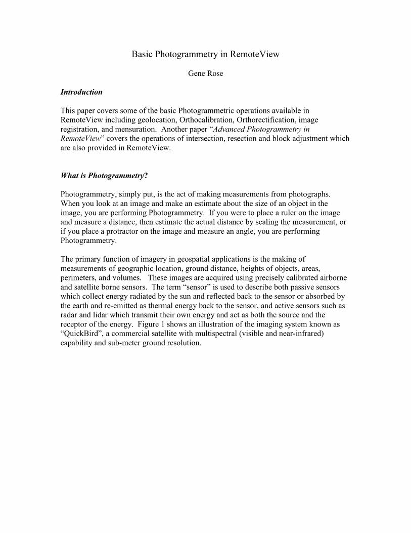
Gene Rose Introduction This paper covers some of the basic Photogrammetric operations available in RemoteView including geolocation, Orthocalibration, Orthorectification, image registration, and mensuration. Another paper “Advanced Photogrammetry in RemoteView” covers the operations of intersection, resection and block adjustment which are also provided in RemoteView. What is Photogrammetry? Photogrammetry, simply put, is the act of making measurements from photographs. When you look at an image and make an estimate about the size of an object in the image, you are performing Photogrammetry. If you were to place a ruler on the image and measure a distance, then estimate the actual distance by scaling the measurement, or if you place a protractor on the image and measure an angle, you are performing Photogrammetry. The primary function of imagery in geospatial applications is the making of measurements of geographic location, ground distance, heights of objects, areas, perimeters, and volumes. These images are acquired using precisely calibrated airborne and satellite borne sensors. The term “sensor” is used to describe both passive sensors which collect energy radiated by the sun and reflected back to the sensor or absorbed by the earth and re-emitted as thermal energy back to the sensor, and active sensors such as radar and lidar which transmit their own energy and act as both the source and the receptor of the energy. Figure 1 shows an illustration of the imaging system known as “QuickBird”, a commercial satellite with multispectral (visible and near-infrared) capability and sub-meter ground resolution.
QuickBird satellite (Illustration)
Regardless of the sensor type, in order to visualize the data, the sensor must convert the raw radiance data that it receives into an image in which the pixels represent quantized levels of this radiance. The main task of Photogrammetry is to determine the precise ground coordinates to which these pixels correspond. Sensors which are used in modern geospatial imaging systems contain precise instruments for determining the location and attitude (roll, pitch and yaw) of the platform at the instant, or over the time span, at which an image is collected. These include Global Positioning System (GPS) receivers, star tracking devices which can determine a precise location based on the relative position of a star field observed by the sensor, and Inertial Navigation Systems (INS) which determine the precise orientation angles of the imaging system about all 3 axes using gyroscopes and accelerometers. In addition, the sensors are precisely calibrated in laboratories to determine their internal characteristics such as camera focal length, lens distortion, offset between the GPS/INS and the sensor, and many other factors which determine the precise relationship between the sensor and the ground at the time each image is obtained.

All of this information can then be encoded into the image metadata or distributed as extra text files with the image so that exploitation tools such as Overwatch’s RemoteView which have the capability to process this information can construct a mathematical “sensor model” for the image. Using this sensor model, any pixel on the image can be related to a ground position and conversely, any point on the ground can be related to a pixel in the image. The first of these processes, the computation of the ground point from the image point, also requires a source of height information in the single-image case, for reasons explained later. In RemoteView, this source can be from standard DTED files including Shuttle Radar Topography Mission (SRTM) data, or from Lidar files, USGS DEM files, or any other elevation source which can be captured in an image format which RemoteView supports. Having an available source of elevation information of the highest possible accuracy is critical for accurate geolocation. RemoteView supports this requirement by automatically loading elevation data from directories which can be cataloged in the Image Catalog. Each time a new image is opened, the corresponding elevation data of the highest available accuracy is also loaded as a virtual “underlay” for the image. It is from this mathematical sensor model that all of the measurements taken from an image are performed, either directly or indirectly. The computation of a distance, for example, depends on first computing the ground coordinates of two image points. These ground points are then input to a standard distance equation. Sensor modeling is at the heart of all Photogrammetry and much emphasis in the Photogrammetric literature is devoted to this field. Since so much of Photogrammetry relies on accurate and consistent sensor models, the U.S. Government has invested heavily in developing a set of common sensor models which can be employed by multiple exploitation systems such as RemoteView. The next section will delve more into the details of the art and science of sensor modeling. Fundamental Applications, Image to Ground and Ground to Image As mentioned above, one of the main tasks of Photogrammetry is to be able to calculate precise geographic coordinates for each pixel of an image, a process known as “Geo Location”. An image which has the proper metadata to allow this process to be done is said to be “Geo Referenced”. Sometimes the two terms are used interchangeably, but here we will stick to this usage. In RemoteView, the process of Geo Referencing an image is fully automated. Users are never required to enter sensor model information such as the type of sensor or the parameters of the sensor. This is handled automatically as shown in Figure 2.
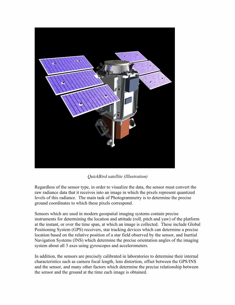
Flow of Geo Referencing and Geo Location on a single image in RemoteView
When a user opens an image in RemoteView, the software automatically determines the best method of georeferencing the image based on its metadata, which is data in the header of the file which determines how it is laid out and its other characteristics. This sensor model is “attached” to the image. Now, when the user moves the mouse, RemoteView “reads” the cursor location and, using the sensor model, converts the pixel coordinates to ground coordinates (Latitude, Longitude and Height or some other ground coordinate system such as MGRS, depending on what the user has selected in the viewer’s coordinate readout control). RemoteView also calculates statistical estimates of the accuracy of the ground coordinate when it is able to from the metadata. These values are called the “Circular Error 90%” and the “Linear Error 90%”, abbreviated CE90 and LE90. These two numbers define the radius and the height of an imaginary cylinder located with it’s base centered on the ground point. In a statistical sense, 90% of the true values of the ground point will fall within this cylinder. Of course, the other 10% of the time, the true values lie somewhere outside of this cylinder. The basis of this calculation depends on the imagery, but for images with Rational Polynomial Coefficients, the errors
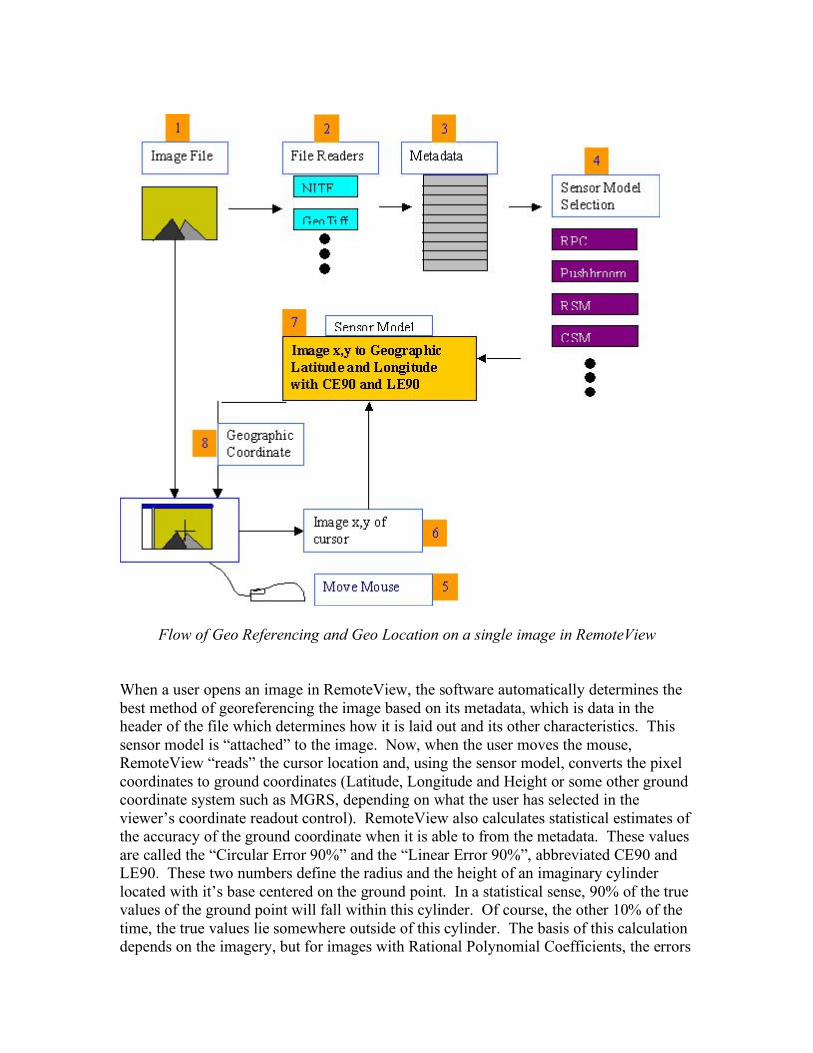
are based mostly on the ERR_RAND an ERR_BIAS tags in the metadata. These are interpreted as 1-sigma random and bias errors respectively, in the plane normal to the look vector, and not including terrain errors. Terrain errors are accounted for separately in the LE90 value on single image error propagation. The results of geolocation, including accuracy are presented in the geo reporting control in the viewer as shown below.
RemoteView georeporting – ground point location, pixel location, RGB values and accuracy
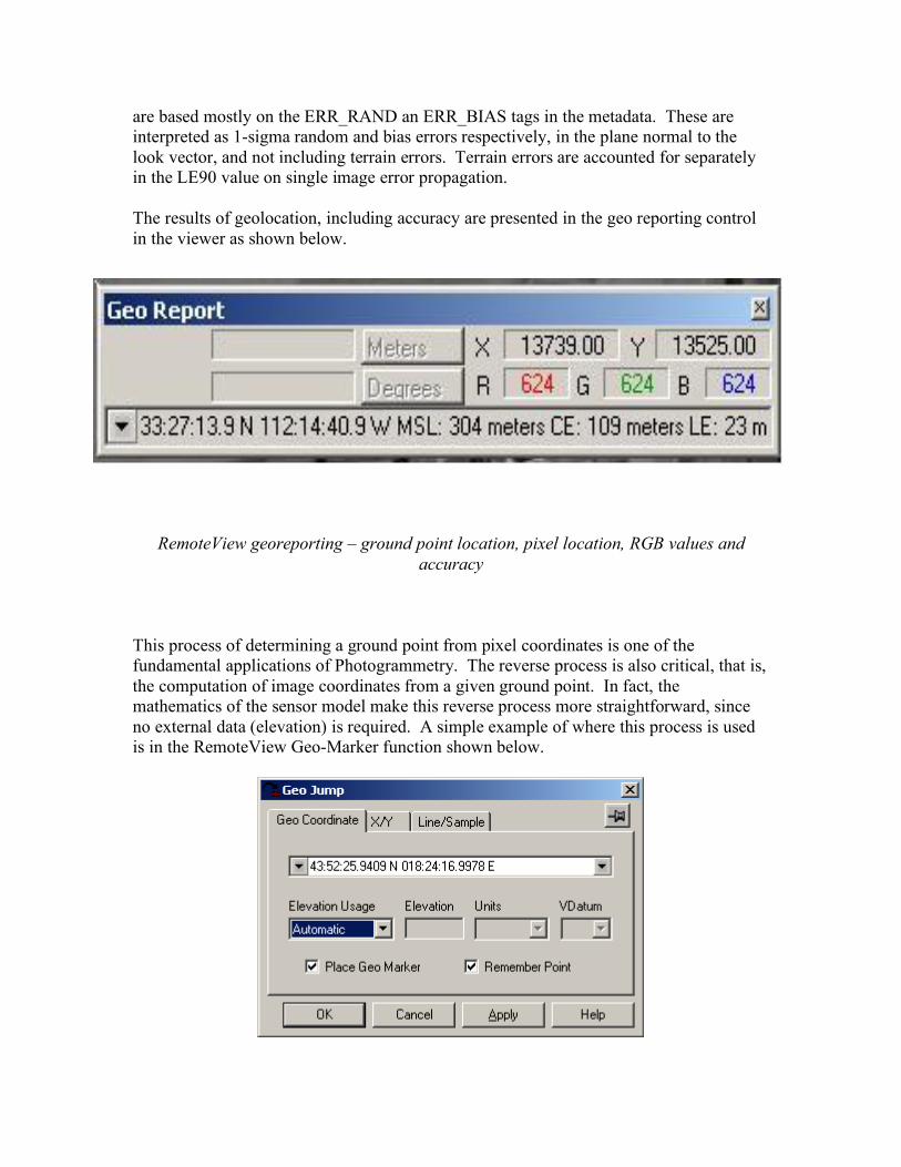
This process of determining a ground point from pixel coordinates is one of the fundamental applications of Photogrammetry. The reverse process is also critical, that is, the computation of image coordinates from a given ground point. In fact, the mathematics of the sensor model make this reverse process more straightforward, since no external data (elevation) is required. A simple example of where this process is used is in the RemoteView Geo-Marker function shown below.
RemoteView Geomarker Application
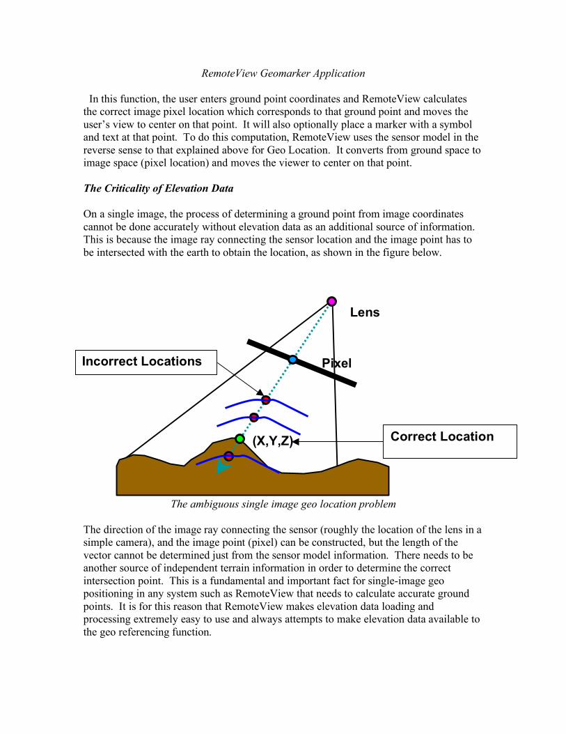
In this function, the user enters ground point coordinates and RemoteView calculates the correct image pixel location which corresponds to that ground point and moves the user’s view to center on that point. It will also optionally place a marker with a symbol and text at that point. To do this computation, RemoteView uses the sensor model in the reverse sense to that explained above for Geo Location. It converts from ground space to image space (pixel location) and moves the viewer to center on that point. The Criticality of Elevation Data On a single image, the process of determining a ground point from image coordinates cannot be done accurately without elevation data as an additional source of information. This is because the image ray connecting the sensor location and the image point has to be intersected with the earth to obtain the location, as shown in the figure below.
The ambiguous single image geo location problem The direction of the image ray connecting the sensor (roughly the location of the lens in a simple camera), and the image point (pixel) can be constructed, but the length of the vector cannot be determined just from the sensor model information. There needs to be another source of independent terrain information in order to determine the correct intersection point. This is a fundamental and important fact for single-image geo positioning in any system such as RemoteView that needs to calculate accurate ground points. It is for this reason that RemoteView makes elevation data loading and processing extremely easy to use and always attempts to make elevation data available to the geo referencing function.
Lens
Pixel (lP,sP)
(X,Y,Z) Correct Location
Incorrect Locations

The interface for setting up automatic loading of terrain data in RemoteView is shown below.
Setting up RemoteView for automatic elevation data loading and usage The elevation data can consist of any combination of standard DTED, USGS DEM, Lidar data in GeoTiff format and any other data source in any file format that RemoteView can read. Terrain data locations can also be ingested automatically into the RemoteView Image Catalog, which is a database of image locations and other metadata is provided with RemoteView. Upon loading any image into RemoteView, the software will also identify any overlapping elevation data, based on the Elevation setup parameters shown above silently load that elevation data as an “underlay” for the image. This data can then be used to determine an accurate ground coordinate for each image pixel. When elevation data has been loaded for an image and is being used for this purpose, this is known as “Ortho
Calibration”, or as “Terrain Correction”. In this case, a message as shown below will be shown in the RemoteView viewer.
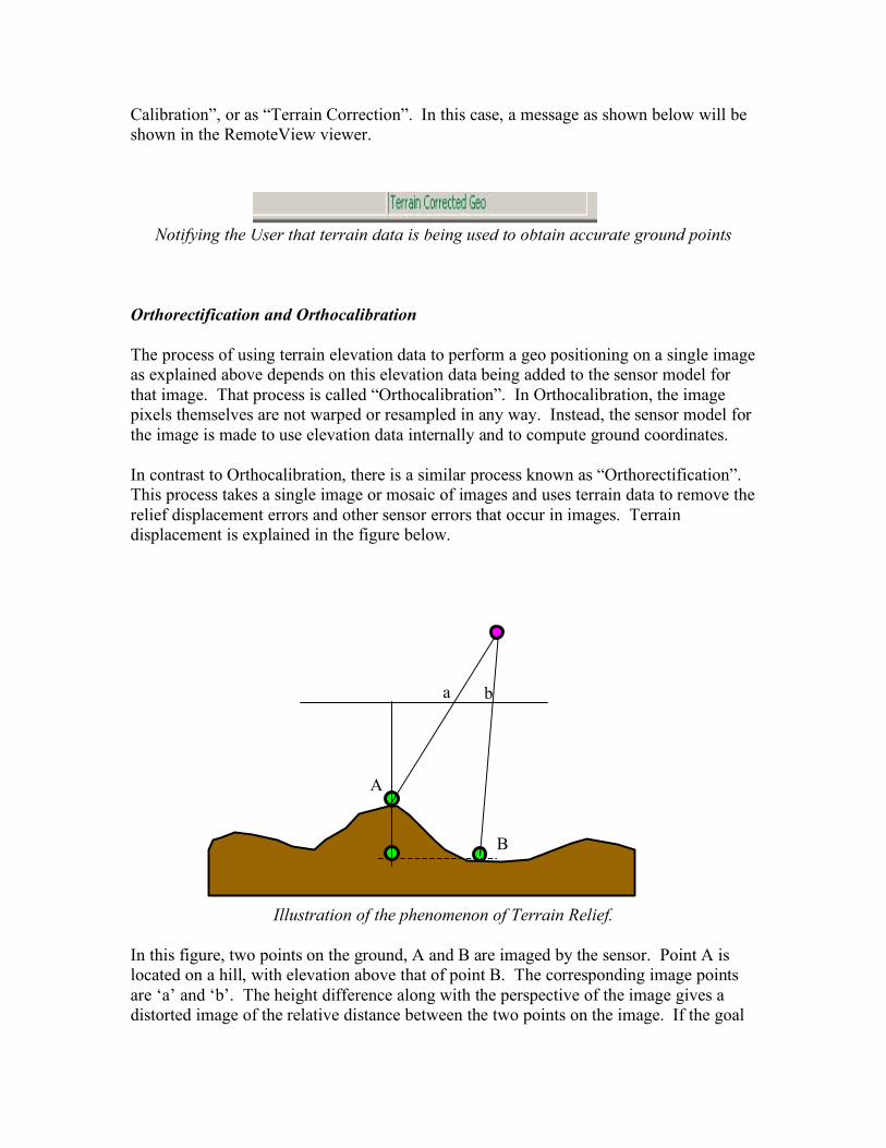
Notifying the User that terrain data is being used to obtain accurate ground points Orthorectification and Orthocalibration The process of using terrain elevation data to perform a geo positioning on a single image as explained above depends on this elevation data being added to the sensor model for that image. That process is called “Orthocalibration”. In Orthocalibration, the image pixels themselves are not warped or resampled in any way. Instead, the sensor model for the image is made to use elevation data internally and to compute ground coordinates. In contrast to Orthocalibration, there is a similar process known as “Orthorectification”. This process takes a single image or mosaic of images and uses terrain data to remove the relief displacement errors and other sensor errors that occur in images. Terrain displacement is explained in the figure below.
Illustration of the phenomenon of Terrain Relief.
In this figure, two points on the ground, A and B are imaged by the sensor. Point A is located on a hill, with elevation above that of point B. The corresponding image points are ‘a’ and ‘b’. The height difference along with the perspective of the image gives a distorted image of the relative distance between the two points on the image. If the goal
A
B
a b

of our image is to portray objects at their correct relative position to one another on the ground, we must remove the effect of the terrain and perspective. If we do this, the image points ‘a’ and ‘b’ will then appear as shown below.
Orthorectification
In this figure, the effects of the terrain have been removed by projecting the two ground points straight up on a line between the point and the base of the figure, called the “Vertical Datum”. This type of perpendicular projection is also called an “Orthographic” projection, which is where the term Orthorectification comes from. In the process of Orthorectification, each pixel in the image is projected straight up from the vertical datum, which is a user defined ellipsoid model of the earth to a new location in the orthorectified image. In the final image, each pixel appears as it would if we could somehow view every pixel directly from above. In fact, this perspective is exactly what traditional paper maps give us. That is why we can view a map and envision the “real” relationships between the objects on the map, their position, size and orientation, and the objects on the earth. Orthorectification in RemoteView is performed from the calibration dialog on the Rectify tab. The user specifies a map projection. The system automatically loads elevation data as explained above or the user can explicitly load it through this dialog. The user interface for performing Orthorectification in RemoteView is shown below.
A
B
a b

Orthorectification User Interface in RemoteView
Notice that there is also a button on this dialog labeled “Adjust Georeferencing Model” which allows a user to further refine the output orthorectified image (also called an “orthophoto”, “image map”, or just “an ortho”). This part of the process is optional. It allows the user to enter known ground points that they may have obtained from a ground survey, a map, another orthophoto or a control image, and to “tie” the orthophoto to those ground points, thus generating a very accurate product. Another way of looking at Orthorectification is shown below. The actual appearance of an orthophoto depends on the map projection which is used to generate it. No map projection can preserve all of the round-earth geometry, different ones attempt to preserve area (Equal Area such as Albers Equal Area), some seek to
preserve relative directions (Conformal such as Lambert Conformal and Mercator) and others attempt to preserve distances (Equi-Distance such as Azimuthal Equidistant, while others try to preserve some of each of these). For a typical high-resolution satellite image or aerial image of a small area, such as an Ikonos or QuickBird image, the differences obtained from these different map projections will usually be very small and hard to see. For images of larger areas such as Landsat, Spot or Radarsat, the differences will be very noticeable and the projection must be chosen with care. Accurate orthophoto generation requires reasonably accurate elevation data, but it does not require elevation data at the same resolution as the image itself. For a typical 1-meter Ikonos image, DTED level 1 terrain data with 30 meter spacing will produce an acceptable result in most cases, for example.
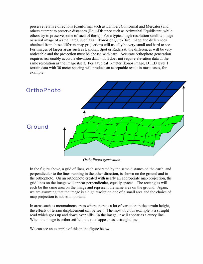
OrthoPhoto generation
In the figure above, a grid of lines, each separated by the same distance on the earth, and perpendicular to the lines running in the other direction, is shown on the ground and in the orthophoto. On an orthophoto created with nearly an appropriate map projection, the grid lines on the image will appear perpendicular, equally spaced. The rectangles will each be the same area on the image and represent the same area on the ground. Again, we are assuming that the image is a high resolution one of a small area and the choice of map projection is not so important. In areas such as mountainous areas where there is a lot of variation in the terrain height, the effects of terrain displacement can be seen. The most obvious example is a straight road which goes up and down over hills. In the image, it will appear as a curvy line. When the image is orthorectified, the road appears as a straight line. We can see an example of this in the figure below.
OrthoPhoto
Ground
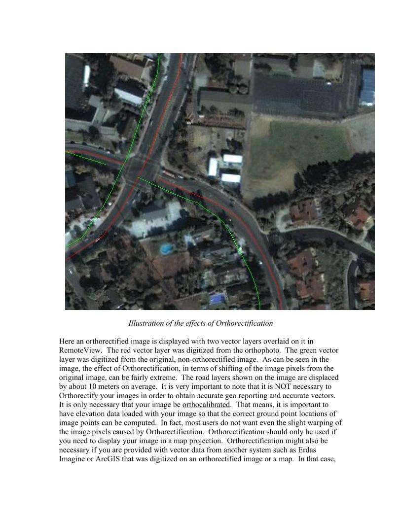
Illustration of the effects of Orthorectification
Here an orthorectified image is displayed with two vector layers overlaid on it in RemoteView. The red vector layer was digitized from the orthophoto. The green vector layer was digitized from the original, non-orthorectified image. As can be seen in the image, the effect of Orthorectification, in terms of shifting of the image pixels from the original image, can be fairly extreme. The road layers shown on the image are displaced by about 10 meters on average. It is very important to note that it is NOT necessary to Orthorectify your images in order to obtain accurate geo reporting and accurate vectors. It is only necessary that your image be orthocalibrated. That means, it is important to have elevation data loaded with your image so that the correct ground point locations of image points can be computed. In fact, most users do not want even the slight warping of the image pixels caused by Orthorectification. Orthorectification should only be used if you need to display your image in a map projection. Orthorectification might also be necessary if you are provided with vector data from another system such as Erdas Imagine or ArcGIS that was digitized on an orthorectified image or a map. In that case,
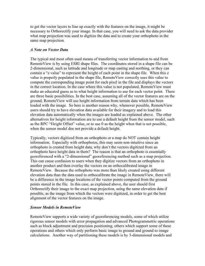
to get the vector layers to line up exactly with the features on the image, it might be necessary to Orthorectify your image. In that case, you will need to ask the data provider what map projection was used to digitize the data and to create your orthophoto in the same map projection. A Note on Vector Data The typical and most often used means of transferring vector information to and from RemoteView is by using ESRI shape files. The coordinates stored in a shape file can be 2-dimensional, such as latitude and longitude or map easting and northing, or they can contain a “z value” to represent the height of each point in the shape file. When this z value is properly populated in the shape file, RemoteView correctly uses this value to compute the corresponding image point for each pixel in the file and displays the vectors in the correct location. In the case where this value is not populated, RemoteView must make an educated guess as to what height information to use for each vector point. There are three basic possibilities. In the best case, assuming all of the vector features are on the ground, RemoteView will use height information from terrain data which has been loaded with the image. So here is another reason why, whenever possible, RemoteView users should try to have elevation data available for their imagery and to load this elevation data automatically when the images are loaded as explained above. The other alternatives for height information are to use a default height from the sensor model, such as the RPC “Height Offset” value, or to use 0 as the height when that is not possible, when the sensor model doe not provide a default height. Typically, vectors digitized from an orthophoto or a map do NOT contain height information. Especially with orthophotos, this may seem non-intuitive since an orthophoto is created from height data, why don’t the vectors digitized from an orthophoto have height data in them? The reason is that an orthophoto is essentially georeferenced with a “2-dimensional” georeferencing method such as a map projection. This can cause confusion to users when they digitize vectors from an orthophoto in another product and then overlay the vectors on an orthocalibrated image in RemoteView. Because the orthophoto was more than likely created using different elevation data than the data used to orthocalibrate the image in RemoteView, there will be a difference in the image locations of the vector points computed from the ground points stored in the file. In this case, as explained above, the user should first Orthorectify their image to the exact map projection, using the same elevation data if possible, as the image from which the vectors were digitized, in order to get the best alignment of the vector features on the image. Sensor Models in RemoteView RemoteView supports a wide variety of georeferencing models, some of which utilize rigorous sensor models with error propagation and advanced Photogrammetric operations such as block adjustment and precision positioning, others which support some of these operations and others which only perform basic image to ground and ground to image calculations. Another way of partitioning these models is by 3-dimensional models and
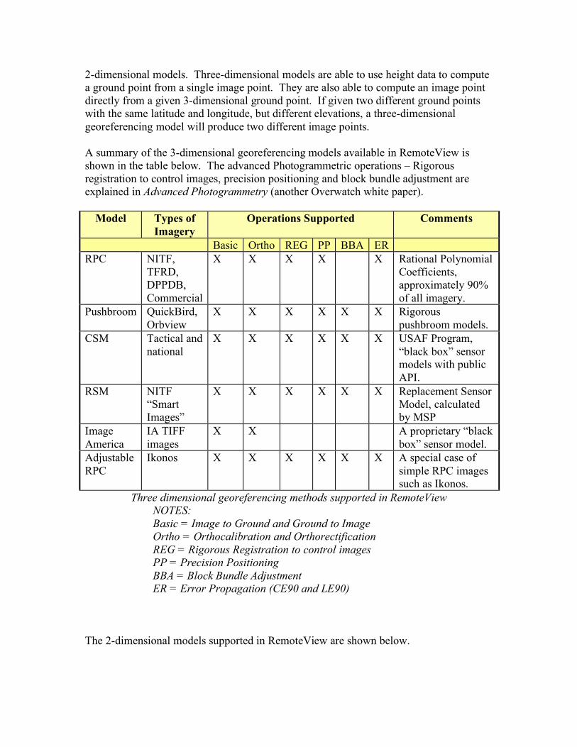
2-dimensional models. Three-dimensional models are able to use height data to compute a ground point from a single image point. They are also able to compute an image point directly from a given 3-dimensional ground point. If given two different ground points with the same latitude and longitude, but different elevations, a three-dimensional georeferencing model will produce two different image points. A summary of the 3-dimensional georeferencing models available in RemoteView is shown in the table below. The advanced Photogrammetric operations – Rigorous registration to control images, precision positioning and block bundle adjustment are explained in Advanced Photogrammetry (another Overwatch white paper).
Model Types of Imagery
Operations Supported Comments
Basic Ortho REG PP BBA ER RPC NITF,
TFRD, DPPDB, Commercial
X X X X X Rational Polynomial Coefficients, approximately 90% of all imagery.
Pushbroom QuickBird, Orbview
X X X X X X Rigorous pushbroom models.
CSM Tactical and national
X X X X X X USAF Program, “black box” sensor models with public API.
RSM NITF “Smart Images”
X X X X X X Replacement Sensor Model, calculated by MSP
Image America
IA TIFF images
X X A proprietary “black box” sensor model.
Adjustable RPC
Ikonos X X X X X X A special case of simple RPC images such as Ikonos.
Three dimensional georeferencing methods supported in RemoteView NOTES: Basic = Image to Ground and Ground to Image Ortho = Orthocalibration and Orthorectification REG = Rigorous Registration to control images PP = Precision Positioning BBA = Block Bundle Adjustment ER = Error Propagation (CE90 and LE90)
The 2-dimensional models supported in RemoteView are shown below.

Model Types of Imagery Comments
Affine DEM, DTED, GeoTiff, Lidar, ICHIPB
A simple 6-parameter coordinate transformation
Polynomial NITF (I2MAPD, GeoTiff, Radarsat, SPOT
These can be 0th, 1st or 2nd order polynomials.
Perspective GeoTiff, Predator A 16-parameter perspective transform.
EOSAT Landsat Map Projections used for Landsat images
Map Projection GeoTiff, RemoteView export
RemoteView supports all of the projections in the USGS projection library.
Two dimensional georeferencing models supported in RemoteView
The 2-dimensional models support only the basic image to ground and ground to image calculations. They cannot be used to create orthophotos nor do they support Orthocalibration or the other advanced Photogrammetric operations. However, any imagery supported by either the 2 or 3 dimensional models can be used in RemoteView’s “non-rigorous” Photogrammetric operations described below, including image to reference, image to image and image to vector calibration. Improving the accuracy of images with RemoteView- Registration, Calibration, etc. Any image with a georeferencing method can be made “more accurate”, in terms of giving ground points which are closer to the true positions of features. There are several ways to do this in RemoteView. This process is known as “Registration” or by “Calibration”. For this paper, we can use the two terms synonymously. In addition, images that have no georeferencing model at all can be given one by RemoteView. These operations work with any of the georeferencing methods described in the tables above, both the 3-dimensional and 2-dimensional models. If there is a source of ground control points (GCPs) available, the user can use the Image to Reference Tool from RemoteView shown below.

Registering an image to Ground Control Points
In one scenario, a user might have access to a ground survey consisting of GPS measured ground points along with image chips which show the exact pixel on the image which corresponds to the ground point. In that case, the user simply digitizes those points at the known pixel location and enters in the known ground coordinates. The tool will then “tie” the image to those ground control points. In another scenario, the user might have highly accurate “control” images, such as DPPDB, NTM, Commercial or other sources of imagery which has a supported 3-D sensor model from the table above. In that case, the user would select the “Multi-Image Intersection” option on the tool and the software will then guide them through the process of identifying appropriate control imagery and extracting ground points using a multi-

image intersection process (described in the white paper “Advanced Photogrammetry”). In this case, the user obtains the benefit of rigorous sensor modeling and Photogrammetric processing and does not need a ground control survey. Using this process in conjunction with an image which also has a supported 3-D sensor model is the best way to perform image registration, such as tactical image registration. In this case, the control points are obtained from the intersection process and those control points are used to actually adjust the sensor model of the tactical or other image being registered, a Photogrammetric process known as “Resection”, which is also described in the advanced Photogrammetry white paper. The accuracy information of the image is also updated in this process, providing new, and often much better, estimates of the CE90 and LE90 of the image being registered. But, as mentioned, this process works with any image, including those that do not have a rigorous sensor model. In cases where it does not, the ground control points, either entered from survey data or computed from control images, are used to compute an adjustment to the images georeferencing information. Once an image has been improved by these processes, it can be saved in a format that will capture all of this improved geo referencing information, that is by saving it to a NITF image and computing RPCs for the image. RemoteView has the capability to compute RPCs from any image that has a 3-dimensional georeferencing model, or from an image that has a 2-dimensional georeferencing model together with elevation data. The RemoteView Image Save tool is used for this purpose. The user should select NITF format and chose “Compute New RPC” on the Format Options. In this way, the saved NITF image with RPCs can be used in the future and by other users without going through the process of registration again. In essence, the ground control point information is now embedded in the new saved image with RPCs. In the absence of ground control points or control images with 3-dimensional sensor model support, the user can use other images such as scanned maps, orthophotos including CIB or any imagery which the user is confident has a more accurate georeferencing method than the image they are trying to improve. One way to do this would be to look at the other image and extract “ground control points” from it and use the tool shown above. But there is a much simpler way, which is by using the image to image calibration tool shown below.

Registering an image to a more accurate image
The image to image registration tool allows the user to place “tie points” on the less accurate image and on the more accurate image. Tie points are simply pixels on both images that represent the same feature on the ground. Examples include any feature that can be identified on both images, such as the intersection of a crosswalk and a street, the corner of a sidewalk, or simply an unidentified “bright pixel” that can be seen in both images. Note that this tool works with a single control image only. This tool provides a quick and robust way to calibrate imagery, including images that have no georeferencing support at all such as JPEGs or Tiffs downloaded from the internet. It features the ability to “auto find” tie points once 2 or more tiepoints have been manually identified. It supports first and second order polynomial adjustments, requiring a minimum of 4 and 10 points for these respectively . It also gives the capability to actually “warp” the image to

the control image, but this is not necessary in order to obtain more accurate georeferencing. Warping should be used only when it is necessary that features in the image match the size and shape and relationship of features in the control image. Warping can cause extreme pixel modifications that typical users do not want. The image to image registration tool is also useful when precise image co-registration is required, for example for performing a multi-spectral pan-sharpening of a multispectral image using a panchromatic image. In this process, better results are sometimes obtained if the 2 images are first co-registered using the image to image calibration tool and a fairly large number of tiepoints. If a small area of the images need to be co-registered, then the tiepoints should be located around that area of the images. Also, a 2nd order polynomial may be required in some cases to achieve sufficient co-registration. The user of “Check points” is also provided with this tool, which allows the user to get an independent “sanity check” on the calibration process. Error values are computed at these check points which represent how well the polynomial adjustment fits at those points. Generally, a good goal is to try to get all of the errors under 1 pixel, but this is not always possible. Mensuration In the domain of image analysis, making basic ground measurements such as distance, area, volume and perimeter is called “Mensuration”. For national imagery, RemoteView supports an interface to the U.S. government standard mensuration service called “Ruler”. Ruler provides hundreds of mensuration tools or “Output Functions” for use with this imagery. The tools are tailored by image and sensor type. In the future, the U.S. government will transition Ruler and other software to the Mensuration Support Program (MSP) and RemoteView will support an interface to this as well. RemoteView also has native mensuration tools for computing: Geodetic Distance, Geodetic Azimuth, Perimeter and Area. All of these computations are based on the best algorithms available in the unclassified domain. Some examples of mensuration are shown in the image below.
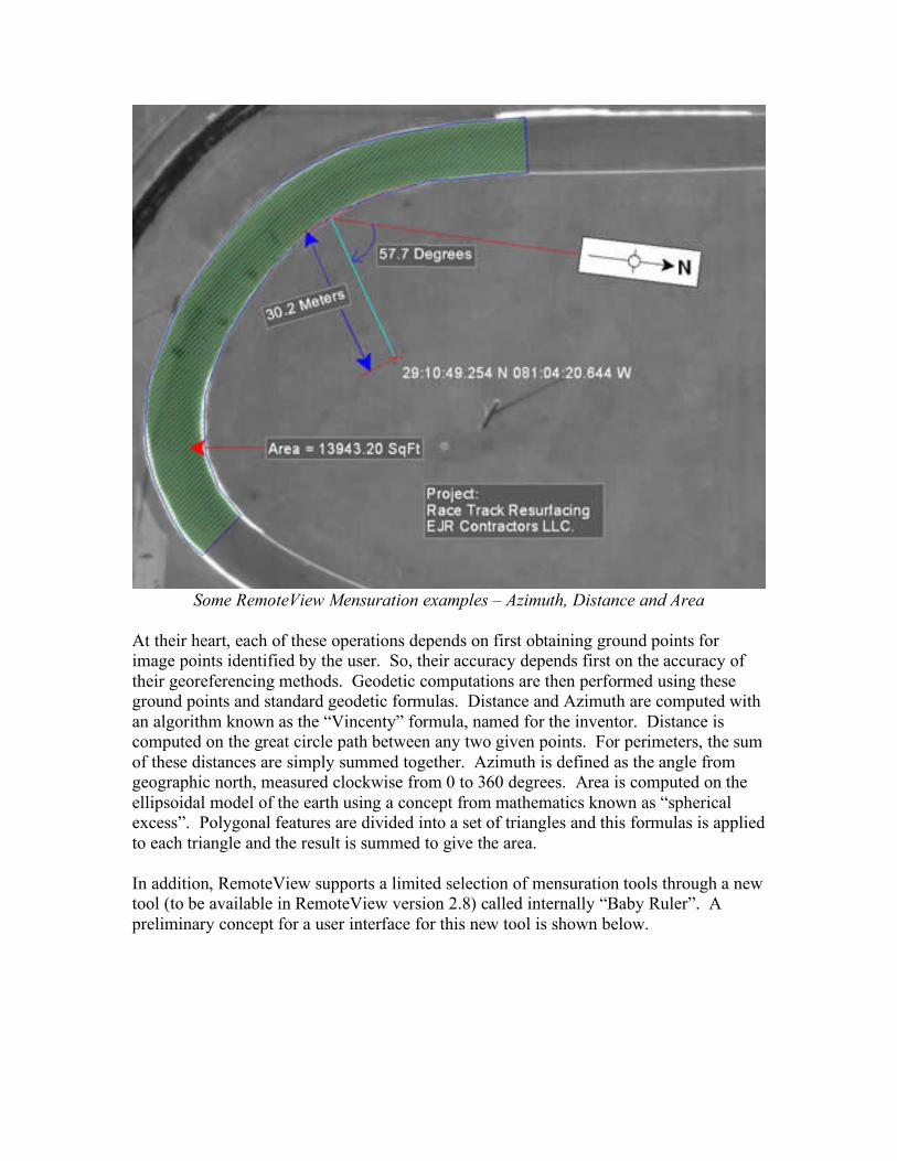
Some RemoteView Mensuration examples – Azimuth, Distance and Area
At their heart, each of these operations depends on first obtaining ground points for image points identified by the user. So, their accuracy depends first on the accuracy of their georeferencing methods. Geodetic computations are then performed using these ground points and standard geodetic formulas. Distance and Azimuth are computed with an algorithm known as the “Vincenty” formula, named for the inventor. Distance is computed on the great circle path between any two given points. For perimeters, the sum of these distances are simply summed together. Azimuth is defined as the angle from geographic north, measured clockwise from 0 to 360 degrees. Area is computed on the ellipsoidal model of the earth using a concept from mathematics known as “spherical excess”. Polygonal features are divided into a set of triangles and this formulas is applied to each triangle and the result is summed to give the area. In addition, RemoteView supports a limited selection of mensuration tools through a new tool (to be available in RemoteView version 2.8) called internally “Baby Ruler”. A preliminary concept for a user interface for this new tool is shown below.

RemoteView Mensuration tool
The operations supported by “Baby Ruler” are shown below.
• Height of an object by clicking on the base of the object and a point on the shadow of the object.
• Height of an object by clicking on the top and bottom of the shadow • Height of an object by clicking on the bottom and top of the object • Center of an object defined by a polygon (3 or more sided) • Distance between two points • Area of an object on the ground defined by a polygon • Direction (Azimuth) of a line defined by two points. • Geographic location of a point determined by clicking on the image.

As shown above, the RemoteView mensuration tool provides a running log of information returned by the various functions as well as instructions on the use of each function. The results of a mensuration session can also be saved out to a word processing file if needed.