basic operation instructions tru-balance 2 tm … · basic operation instructions tru-balance 2...
TRANSCRIPT

BASIC OPERATION INSTRUCTIONS
TRU-Balance 2Power Positioning Systems
TM
Includes: TRU-Balance 2 Power Tilt, TRU-Balance 2 Power Recline, TRU-Balance 2 Power Tilt and Recline, and TRU-Balance 2 Power Lift and Tilt
ACN# 088 609 661

TRU-Balance 2 Power Positioning Systems www.quantumrehab.com
Copyright © 2008Pride Mobility Products CorporationINFMANU3700/Rev C/October 2008
WARNING! A Quantum Rehab Provider or a qualifiedtechnician must perform the initial setup of this productand must perform all of the instructions in this manual.
The symbols below are used throughout this owner's manual and on theproduct to identify warnings and important information. It is very importantfor you to read them and understand them completely.
WARNING! Indicates a potentially hazardous condition/situation. Failure to follow designated procedures cancause either personal injury, component damage, ormalfunction. On the product, this icon is represented as ablack symbol on a yellow triangle with a black border.
MANDATORY! These actions should be performed asspecified. Failure to perform mandatory actions can causepersonal injury and/or equipment damage. On the product,this icon is represented as a white symbol on a blue dotwith a white border.
PROHIBITED! These actions are prohibited. These actionsshould not be performed at any time or in anycircumstances. Performing a prohibited action can causepersonal injury and/or equipment damage. On the product,this icon is represented as a black symbol with a red circleand a red slash.
NOTE: These instructions are compiled from the latest specifications andproduct information available at the time of publication. We reserve theright to make changes as they become necessary. Any changes to ourproducts may cause slight variations between the illustrations and expla-nations in this manual and the product you have purchased. The latest/current version of this manual is available on our website.
088 609 661
S A F E T Y G U I D E L I N E S

www.quantumrehab.com TRU-Balance 2 Power Positioning Systems
LABEL INFORMATION.................................................................. 4
INTRODUCTION ............................................................................ 5
THE TRU-BALANCE 2 POWER POSITIONING SYSTEM ........... 7
PRECAUTIONARY GUIDELINES ................................................. 7
OPERATING THE TRU-BALANCE 2 POWER POSITIONING SYSTEM ...................................................................................... 13
ARMREST OPTIONS .................................................................. 27Flip-Up .................................................................................... 27Heavy Duty Drop-In ............................................................... 29Single Post Quick Height Adjustable Drop-In ...................... 31Two Post Height Adjustable Flip-Up ...................................... 34Shear Reduction .................................................................... 36
CONTROLLER POSITION .......................................................... 37
POWER SEAT ELEVATOR OPTION ......................................... 38
MANUAL RECLINE OPTION (TRU-BALANCE 2 POWER TILT ONLY) .......................................................................................... 39
CARE AND MAINTENANCE ...................................................... 40
WARRANTY ................................................................................ 40
T A B L E O F C O N T E N T S

TRU-Balance 2 Power Positioning Systems www.quantumrehab.com
Read and follow the information in the owner’s manual.
Avoid exposure to rain, snow, ice, salt, or standing water whenever possible. Maintain and store in a clean and dry condition.
EMI-RFI - This product has been tested and passed at animmunity level of 20 V/m.
Use correct tie-down points for controller harness toprevent the harness from getting caught in the drive tires,pinched in the seat frame, or damaged when passingthrough doorways.
Maximum seating weight
Pinch/Crush points created during assembly.
Consult your Quantum Rehab Providerbefore making any changes to yourseating system configuration.
PRODUCT SAFETY SYMBOLSThe symbols below are used on the seating system to identify warnings,mandatory actions, and prohibited actions. It is very important for you toread and understand them completely.
L A B E L I N F O R M A T I O N

Basic Operation Instructions 5
www.quantumrehab.com TRU-Balance 2 Power Positioning Systems
INTRODUCTIONWELCOME to Quantum Rehab, a division of Pride Mobility Products Cor-poration (Pride). The product you have purchased combines state-of-the-artcomponents with safety, comfort, and styling in mind. We are confident thatthe design features will provide you with the conveniences you expect dur-ing your daily activities. Understanding how to safely operate and care forthis product should bring you years of trouble free operations and service.
Read and follow all instructions, warnings, and notes in this manual beforeattempting to operate your product for the first time. You must also read allinstructions, warnings, and notes contained in any supplemental instruc-tional booklets for the controller, front riggings, and/or seating system thataccompanied your power chair before initial operation. Your safetydepends upon you, as well as your provider, caretaker, or healthcare profes-sional in using good judgement.
This manual is to be used in addition to the power base owner’s manual thatcame with your power chair. If there is any information in this manual whichyou do not understand, or if you require additional assistance for setup oroperation, please contact your Quantum Rehab Provider. Failure to followthe instructions, warnings, and notes in this manual and those locatedon your Pride product can result in personal injury and/or productdamage and will void Pride’s product warranty.
PURCHASER’S AGREEMENT By accepting delivery of this product, you promise that you will not change,alter, or modify this product or remove or render inoperable or unsafe anyguards, shields, or other safety features of this product; fail, refuse, orneglect to install any retrofit kits from time to time provided by Pride toenhance or preserve the safe use of this product.
INFORMATION EXCHANGEWe want to hear your questions, comments, and suggestions about this man-ual. We would also like to hear about the safety and reliability of your newPride product, and about the service you received from your QuantumRehab Provider. Please notify us of any change of address, so we can keepyou apprised of important information about safety, new products, and newoptions that can increase your ability to use and enjoy your Pride product.

6 Basic Operation Instructions
Please feel free to contact us at the following address:
Pride Mobility Products CorporationAttn: Customer Care Department
182 Susquehanna AvenueExeter, PA 18643-2694
NOTE: If you ever lose or misplace your product registration card or yourcopy of this manual, contact us and we will be glad to send you a new oneimmediately.
My Quantum Rehab Provider Is:
Name:
Address:
Phone Number:
Purchase Date:
TRU-Balance 2 Power Positioning Systems www.quantumrehab.com

Basic Operation Instructions 7
THE TRU-BALANCE 2 POWER POSITIONING SYSTEMThe TRU-Balance 2 Power Positioning System is a unique seating system designed spe-cifically for the Pride Power Chair. It is fully adjustable to meet the individual needs ofthe user, and it is mounted to a Pride power base to provide maximum maneuverability.
Reusable hook and loop fasteners are included in your owner’s package for use inattaching the seat cushion to the seat base. These fasteners are not intended for useon cushions with anti-skid material, as they may damage the seat cushion.
Figures 1, 2, 3, and 4 provide information on the TRU-Balance 2 Power Tilt,TRU-Balance 2 Power Recline, TRU-Balance 2 Power Tilt and Recline,and TRU-Balance 2 Lift and Tilt components. Use these diagrams to famil-iarize yourself with the function and location of each component beforeusing the TRU-Balance 2 Power Positioning System.
PRECAUTIONARY GUIDELINESBefore operating the TRU-Balance 2 Power Positioning System, please readthe following. These guidelines are provided for your benefit and will aidyou in the safe operation of the seating system.
Turn off the power before you are seated in the TRU-Balance 2 PowerPositioning System.Always have assistance when you are being seated in the TRU-Balance2 Power Positioning System.Follow all of the procedures and heed the warnings as explained in yourpower chair owner’s manual.
WARNING! The center of gravity of your seating system wasfactory set to a position that meets the needs of thedemographic majority of users. Your Quantum Rehab Providerhas evaluated your seating system and made any necessaryadjustments to suit your specific requirements. Do not changeyour seating configuration without first contacting PrideMobility Products or your Quantum Rehab Provider.
WARNING! Should the fittings on your seating systembecome loose, report the problem immediately to yourQuantum Rehab Provider.
WARNING! In the event of a loss of power to the powerchair, transfer to a safe position, seeking assistance ifneeded. Contact your Quantum Rehab Providerimmediately to report the incident.
www.quantumrehab.com TRU-Balance 2 Power Positioning Systems

8 Basic Operation Instructions
WARNING! Your seating system is not approved for use asa seat in any vehicle. Use the seats and occupantrestraints provided by the manufacturer of the vehicle.
MANDATORY! Do not exceed the weight capacity listed inyour power chair owner’s manual or 300 lbs. (136 kg),whichever is less.
Electromagnetic and Radio Frequency Interference (EMI/RFI)
WARNING! Laboratory tests have shown that electromagneticand radio frequency waves can have an adverse affect on theperformance of electrically-powered mobility vehicles.
Electromagnetic and Radio Frequency Interference can come from sourcessuch as cellular phones, mobile two-way radios (such as walkie-talkies), radiostations, TV stations, amateur radio (HAM) transmitters, wireless computerlinks, microwave signals, paging transmitters, and medium-range mobiletransceivers used by emergency vehicles. In some cases, these waves cancause unintended movement or damage to the control system. Every electri-cally-powered mobility vehicle has an immunity (or resistance) to EMI. Thehigher the immunity level, the greater the protection against EMI. This prod-uct has been tested and has passed at an immunity level of 20 V/m.
WARNING! Be aware that cell phones, two-way radios,laptops, and other types of radio transmitters may causeunintended movement of your electrically-powered mobilityvehicle due to EMI. Exercise caution when using any ofthese items while operating your mobility vehicle and avoidcoming into close proximity of radio and TV stations.
WARNING! The addition of accessories or components tothe electrically-powered mobility vehicle can increase thesusceptibility of the vehicle to EMI. Do not modify yourpower chair in any way not authorized by Pride.
WARNING! The electrically-powered mobility vehicle itselfcan disturb the performance of other electrical deviceslocated nearby, such as alarm systems.
NOTE: For further information on EMI/RFI, go to the Resource Centeron www.pridemobility.com. If unintended motion or brake release occurs,turn your power chair off as soon as it is safe to do so. Call Pride or yourQuantum Rehab Provider to report the incident.
TRU-Balance 2 Power Positioning Systems www.quantumrehab.com
Basic Operation Instructions 9
www.quantumrehab.com TRU-Balance 2 Power Positioning Systems
Figure 1. TRU-Balance 2 Power Tilt Components
MANUALRECLINE BACK(OPTIONAL)With this option, theseatback can beadjusted to recline toan angle between 90 and 180 .
ARMRESTSAvailable in fourbasic styles:
Heavy Duty Drop-in
Flip-up(standard)
Single Post Quick Height Adjustable
Drop-in(available in adultor pediatric sizes)
Two Post HeightAdjustable Flip-up
4-WAY TOGGLE CONTROLS (OPTIONAL)Allow the user to controlthe tilt, seat elevator, andarticulating leg restactuators (if so equipped).
4-way ButtonToggle
4-way Toggle Quad Push-ButtonControl
ATTENDANT CONTROLMODULEAllows an attendant tocontrol the actuators. Anyaction made through theAttendant Control Moduleoverrides the toggle actionsmade by the user.

TRU-Balance 2 Power Positioning Systems www.quantumrehab.com
10 Basic Operation Instructions
Figure 2. TRU-Balance 2 Power Recline and TRU-Balance 2 Power Tilt and Recline Components
SHEAR REDUCTION ARMRESTSAllow the armrests to beflipped back or removedwhenever necessary.
ATTENDANT CONTROLMODULEAllows an attendant tocontrol the actuators. Anyaction made through theAttendant Control Moduleoverrides the toggle actionsmade by the user.
POWER RECLINE
POWER TILT AND RECLINE
4-WAY TOGGLE CONTROLS (OPTIONAL)Allows the user to controlthe tilt, seat elevator, andarticulating leg restactuators (if so equipped).
4-way ButtonToggle
4-way Toggle Quad Push-ButtonControl

Basic Operation Instructions 11
www.quantumrehab.com TRU-Balance 2 Power Positioning Systems
Figure 3. TRU-Balance 2 Power Lift and Tilt Components
ARMRESTSAvailable in four basic styles:
Heavy Duty Drop-inFlip-up(standard)
Single Post Quick Height Adjustable
Drop-in(available in adultor pediatric sizes)
Two Post HeightAdjustable Flip-up
ATTENDANT CONTROLMODULEAllows an attendant tocontrol the actuators. Anyaction made through theAttendant Control Moduleoverrides the toggle actions made by the user.

TRU-Balance 2 Power Positioning Systems www.quantumrehab.com
12 Basic Operation Instructions
Figure 4. TRU-Balance 2 Power Lift and Tilt with Optional Recline Components
SHEAR REDUCTIONREMOVABLE ARMRESTSAllow the armrests to beflipped back or removedwhenever necessary.
ATTENDANT CONTROLMODULEAllows an attendant tocontrol the actuators. Anyaction made through theAttendant Control Moduleoverrides the toggle actionsmade by the user.

Basic Operation Instructions 13
www.quantumrehab.com TRU-Balance 2 Power Positioning Systems
OPERATING THE TRU-BALANCE 2 POWER POSITIONINGSYSTEMThe TRU-Balance 2 Power Positioning System can be operated through a PGor Q-Logic controller, a specialty controller, or a toggle (see figure 9, 10, 11,12, or 13). Your TRU-Balance Seating System provides up to 55° of tilt, canrecline 95°-168°, and can tilt/recline up to 168°. See figures 1, 2, 3 and 4.
NOTE: Certain configurations of a TRU-Balance 2 Power Tilt on aQuantum R-4000 power base have a maximum tilt angle of 45°.
There is a power inhibit on your TRU-Balance 2 Power Positioning Systemwhich will not allow you to drive your power chair while in the tilt position.A full inhibit will activate at 20°-55°. See figure 5.
Figure 5. Inhibit Matrix
WARNING! Check the immediate area to ensure nothing istrapped in the mechanism before operating the tilt, recline,or lift features. Keep clear prior to and during movement.
NOTE: If your TRU-Balance 2 Power Positioning System is equipped withpower tilt features, your seating system may be equipped with safety pressureswitches. If any obstruction is detected on the switch area while you are attempt-ing to return to a sitting position, the tilt mechanism will automatically stop.
NOTE: There are no safety pressure switches if your TRU-Balance 2 PowerPositioning System is equipped with both a power tilt and a power elevating seat.
NOTE: The addition of an optional vent tray to your TRU-Balance 2Power Positioning System may change the overall weight, size, and/orcenter of gravity of your power chair. Do not make any changes to yourseating configuration without contacting your Quantum Rehab Provider.
Recline Lock Out
Tilt Lock Out
Elevate Lock Out
1/4 Speed
Full Drive Lock Out
Elevated X X Active
Tilted more than 20° X Active
Reclined more than 20° X Active
Tilted/reclined more than 170°
X X X Active

TRU-Balance 2 Power Positioning Systems www.quantumrehab.com
14 Basic Operation Instructions
Figure 6. TRU-Balance 2 Power Tilt and Recline Range of Motion
95
Minimum Recline Angle
168
168
55
Maximum Tilt Angle
Maximum Recline Angle
Safety PressureSwitches
Maximum Combined Recline and Tilt Angle
5545*
* The maximum tilt angle of certain configurations on a Quantum R-4000 is 45 .
45*

Basic Operation Instructions 15
www.quantumrehab.com TRU-Balance 2 Power Positioning Systems
50
10 in. (25.4 cm)
Figure 7. TRU-Balance 2 Power Lift and Tilt Range of Motion

TRU-Balance 2 Power Positioning Systems www.quantumrehab.com
16 Basic Operation Instructions
Figure 8. TRU-Balance 2 Power Lift and Tilt with Optional Recline Range of Motion
95
10 in. (25.4 cm)
168
180

Basic Operation Instructions 17
www.quantumrehab.com TRU-Balance 2 Power Positioning Systems
Figure 9. 2-way Fixed-Mount ToggleOperation
NOTE: This manual will discuss toggle and joystick operations only. Ifyour TRU-Balance 2 Power Positioning System is equipped with a differ-ent operating device, please refer to the operation manual supplied withthat device and/or your power chair owner’s manual.
Toggle OperationYour TRU-Balance 2 Power Positioning System may be equipped witheither one of two 2-way toggles or one of three available 4-way toggles.
NOTE: Your TRU-Balance 2 Power Positioning System may be equippedwith any number of these functions.
The 2-way fixed-mount toggle and the2-way multi-position toggle functionthe same way. See figures 9 and 10.
2-way Toggles1. To tilt backward, pull the toggle
switch backward.2. To return to a sitting position, push
the toggle switch forward.
Figure 10. 2-way Multi-Position ToggleOperation
18 Basic Operation Instructions
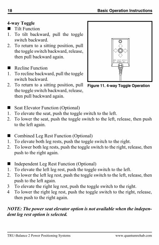
Figure 11. 4-way Toggle Operation
4-way ToggleTilt Function
1. To tilt backward, pull the toggleswitch backward.
2. To return to a sitting position, pullthe toggle switch backward, release,then pull backward again.
Recline Function1. To recline backward, pull the toggle
switch backward.2. To return to a sitting position, pull
the toggle switch backward, release,then pull backward again.
Seat Elevator Function (Optional)1. To elevate the seat, push the toggle switch to the left.2. To lower the seat, push the toggle switch to the left, release, then push
to the left again.
Combined Leg Rest Function (Optional)1. To elevate both leg rests, push the toggle switch to the right.2. To lower both leg rests, push the toggle switch to the right, release, then
push to the right again.
Independent Leg Rest Function (Optional)1. To elevate the left leg rest, push the toggle switch to the left.2. To lower the left leg rest, push the toggle switch to the left, release, then
push to the left again.3 To elevate the right leg rest, push the toggle switch to the right.4 To lower the right leg rest, push the toggle switch to the right, release,
then push to the right again.
NOTE: The power seat elevator option is not available when the indepen-dent leg rest option is selected.
TRU-Balance 2 Power Positioning Systems www.quantumrehab.com

Basic Operation Instructions 19
Figure 12. 4-way Button ToggleOperation
2. To return to a sitting position, pull the to
4-way Button ToggleTilt Function
1. To tilt backward, pull the toggle buttonbackward.
2. To return to a sitting position, pull thetoggle button backward, release, thenpull backward again.
Recline Function1. To recline backward, pull the toggle
switch backward.
ggle button backward, release,then pull backward again.
Seat Elevator Function (Optional)1. To elevate the seat, push the toggle button to the left.2. To lower the seat, push the toggle button to the left, release, then push
to the left again.
Combined Leg Rest Function (Optional)1. To elevate both leg rests, push the toggle button to the right.2. To lower both leg rests, push the toggle button to the right, release, then
push to the right again.
Independent Leg Rest Function (Optional)1. To elevate the left leg rest, push the toggle button to the left.2. To lower the left leg rest, push the toggle button to the left, release, then
push to the left again.3. To elevate the right leg rest, push the toggle button to the right.4. To lower the right leg rest, push the toggle button to the right, release,
then push to the right again.
NOTE: The power seat elevator option is not available when the indepen-dent leg rest option is selected.
www.quantumrehab.com TRU-Balance 2 Power Positioning Systems

20 Basic Operation Instructions
Figure 13. Quad Push-Button Control Toggle
1
2
3
4
Quad Push-Button Control ToggleTilt Function
1. To tilt backward, push the first button.2. To return to a sitting position, push the
button again.
Recline Function 1. To recline backward, push the second
button.2. To return to a sitting position, push the
button again.
Seat Elevator Function (Optional)
Operation1. To elevate the seat, push the third button.2. To lower the seat, push the third button again.
Combined Leg Rest Function (Optional)1. To elevate both leg rests, push the fourth button.2. To lower both leg rests, push the fourth button again.
Independent Leg Rest Function (Optional)1. To elevate the left leg rest, push the third button.2. To lower the left leg rest, push the third button again.3. To elevate the right leg rest, push the fourth button.4. To lower the right leg rest, push the fourth button again.
NOTE: The power seat elevator option is not available when the indepen-dent leg rest option is selected.
TRU-Balance 2 Power Positioning Systems www.quantumrehab.com

Basic Operation Instructions 21
www.quantumrehab.com TRU-Balance 2 Power Positioning Systems
Recline Mode Tilt Mode Elevating Seat Mode
ALR/ELR Mode (both) ALR/ELR Mode (right) ALR/ELR Mode (left)
Figure 14. Actuator Modes (Remote Plus)
Remote Plus Joystick Operation1. Press the On/Off Key to power on the chair and the controller.2. Press the Mode Key twice to select actuator adjustment mode.3. Push the joystick to the right to cycle through the available actuators
until the desired actuator is illuminated on the actuator indicator. Seefigure 14.
4. Pull the joystick backward to activate the actuator or push the joystickforward to return to your original position.
5. Press the Mode Key again to return to the drive mode.

TRU-Balance 2 Power Positioning Systems www.quantumrehab.com
22 Basic Operation Instructions
Q-Logic Operation1. Push the On/Off and Mode Select Lever up once to power on the chair
and the controller.2. Push the On/Off and Mode Select Lever up several times until the seat
screen is displayed on the LCD or push the key 2 select button once togo directly to actuator mode.
3. Push the joystick to the left or right to cycle through the availableactuators until the desired actuators are illuminated on the actuatorindicator. See figure 15.
4. When the desired actuator is selected, give a forward command to thejoystick to adjust position in one direction or give a reverse command tothe joystick to adjust position in the opposite direction.
5. Push and release the On/Off and Mode Select Lever until you return tothe desired drive profile.
Figure 15. Actuator Modes (Q-Logic)
Recline & ELR/ALR Mode (Both)
Tilt Mode
ALR/ELR Mode (both)
Elevating Seat Mode
ALR/ELR Mode (right)
Recline Mode
ALR/ELR Mode (left)

Basic Operation Instructions 23
Attendant Control Module OperationYour seating system may be equipped with one of two available AttendantControl Modules (see figures 16 and 17). The actuators can be adjustedeither by the user through the controller or the toggle, or by an attendantthrough the Attendant Control Module. Any action made through the Atten-dant Control Module will override toggle actions made by the user.
Actuator Indicator
Power Key
Figure 16. Remote Plus Attendant Control Module
NOTE: Your TRU-Balance 2 Power Positioning System may be equippedwith some or all of these functions.
Remote Plus Attendant Control ModuleTo adjust any of the actuators, press Select to cycle until the desired actuatoris illuminated on the actuator indicator (see figure 16), then press the up arrowto activate the actuator or the down arrow to return to your original position.
Tilt Function 1. Press the power key to power on the module.2. Press Select until the actuators in both the back and seat are illuminated
on the actuator indicator on the module. Use the up and down arrows toincrease or decrease the degree of tilt.
3. To return to a sitting position, press Select until the actuators in both theback and seat are illuminated on the actuator indicator on the module,and then press the down arrow until the seat is in a sitting position.
www.quantumrehab.com TRU-Balance 2 Power Positioning Systems

TRU-Balance 2 Power Positioning Systems www.quantumrehab.com
24 Basic Operation Instructions
Recline Function 1. Press the power key to power on the module.2. Press Select until the actuator on the back is illuminated on the actuator
indicator on the module. Use the up and down arrows to increase ordecrease the angle of recline.
3. To return to a sitting position, press Select until the actuator on the backis illuminated on the actuator indicator on the module, and then press thedown arrow until the seat is in an upright position.
Seat Elevator Function (Optional)1. Press the power key to power on the module.2. Press Select until the actuator on the seat is illuminated on the actuator
indicator on the module. Use the up and down arrows to increase ordecrease the height of the seat.
3. To lower the seat to its original position, press Select until the actuator onthe seat is illuminated on the actuator indicator on the module, and thenpress the down arrow until the seat is lowered to its original position.
Leg Rest Function (Optional)1. Press the power key to power on the module.2. Press Select until the desired leg rest actuator is illuminated on the
actuator indicator on the module. Use the up and down arrows toincrease or decrease the degree of elevation.
3. To return the leg rest to a lowered position, press Select until the desiredleg rest actuator is illuminated on the actuator indicator on the module,and then press the down arrow until the leg rest is in a lowered position.
Independent/Combined Leg Rest Function (Optional)1. Press the power key to power on the module.2. Press Select to cycle through the left, right, and combined leg rests until
the desired leg rest actuator is illuminated on the actuator indicator onthe module. Use the up and down arrows to increase or decrease thedegree of elevation.
3. To return the leg rest to a lowered position, press Select to cycle throughthe left, right, and combined leg rests until the desired leg rest actuatoris illuminated on the actuator indicator on the module, and then press thedown arrow until the leg rest is in a lowered position.

Basic Operation Instructions 25
www.quantumrehab.com TRU-Balance 2 Power Positioning Systems
Figure 17. Q-Logic Attendant Control Module
Actuator Indicator(Seatback)
(Seat)(Left Leg)
(Right Leg)
Mode KeyPower Key
Joystick
NOTE: Your TRU-Balance 2 Power Positioning System may be equippedwith some or all of these functions.
Q-Logic Attendant Control ModuleTo adjust any of the actuators, press the mode key twice and then push thejoystick to the right to cycle until the desired actuator is illuminated on theactuator indicator (see figure 17). Move the joystick forward or backward toactivate the desired actuator.
Tilt Function 1. Press the power key to power on the module.2. Press the mode key twice and then push the joystick to the right until the
actuators in both the back and seat are illuminated on the actuator indicatoron the module. Pull the joystick backward to increase the degree of tilt.
3. To return to a sitting position, ensure the actuators in both the back andseat are illuminated on the actuator indicator, then push the joystickforward to decrease the degree of tilt.

TRU-Balance 2 Power Positioning Systems www.quantumrehab.com
26 Basic Operation Instructions
Recline Function 1. Press the power key to power on the module.2. Press the mode key twice and then push the joystick to the right until the
actuator in the back is illuminated on the actuator indicator on themodule. Pull the joystick backward to increase the angle of recline.
3. To return to a sitting position, press the mode key twice and then pushthe joystick to the right until the actuator in the back is illuminated onthe actuator indicator on the module. Push the joystick forward todecrease the angle of recline.
Seat Elevator Function (Optional)1. Press the power key to power on the module.2. Press the mode key twice and then push the joystick to the right until the
actuator in the seat is illuminated on the actuator indicator on themodule. Pull the joystick backward to increase the height of the seat.
3. To lower the seat, press the mode key twice and then push the joystick to theright until the actuator in the seat is illuminated on the actuator indicator onthe module. Push the joystick forward to decrease the height of the seat.
Leg Rest Function (Optional)1. Press the power key to power on the module.2. Press the mode key twice and then push the joystick to the right until the
actuator in the desired leg rest is illuminated on the actuator indicator onthe module. Pull the joystick backward to raise the leg rest.
3. To lower the leg rest, press the mode key twice and then push thejoystick to the right until the actuator in the desired leg rest isilluminated on the actuator indicator on the module. Push the joystickforward to decrease the height of the leg rest.
Independent/Combined Leg Rest Function (Optional)1. Press the power key to power on the module.2. Press the mode key twice and then push the joystick to the right until the
actuator(s) in the left, right, or combined leg rest is illuminated on the actuatorindicator on the module. Pull the joystick backward to raise the leg rest(s).
3. To lower the leg rest(s), press the mode key twice and then push thejoystick to the right until the actuator(s) in the left, right, or combinedleg rest is illuminated on the actuator indicator on the module. Push thejoystick forward to decrease the height of the leg rest(s).

Basic Operation Instructions 27
www.quantumrehab.com TRU-Balance 2 Power Positioning Systems
Figure 18. Flip-Up Armrest Angle Adjustment
Turn screw clockwiseto tilt armrest downwards.
Turn screw counterclockwise totilt armrest upwards.
ArmrestAngle
SupportBracket
ButtonHead
Screw
ArmrestAngle
SupportBracket
ButtonHead
Screw
Jam Nut Jam Nut
ARMREST OPTIONSThe following sections will describe armrest options and the comfort adjustmentsthat can be made to them. Not all armrest options are available on all TRU-Balance2 Power Positioning Systesm. Refer to figures 1, 2, 3, and 4 for armrest availability.
You may need the following to make comfort adjustments:standard hex key setstandard open-ended wrenchPhillips screwdriver
WARNING! Do not attempt to lift or move your power chair orseating system by any of its removable parts, including thearmrest(s), front rigging(s), seat cushions, seatback, shrouds,or controller. Use only solid, non-removable frame componentsto lift or move your power chair or seating system.
WARNING! Avoid putting all of your weight on the powerchair armrests and do not use the armrests for weightbearing purposes, such as transfers. Such use may causethe power chair to tip, resulting in a fall from the powerchair and personal injury.
Flip-Up ArmrestsThe Flip-Up Armrests are attached to the seat canes and are designed to “flip-up” out of the way for easier transfer onto and off of the power chair. Both thearmrest angle and the armrest height can be adjusted on the Flip-Up Armrests.
To adjust the armrest angle:1. Flip the armrests up and out of the way. 2. Loosen the jam nut located on the armrest angle support bracket. See figure 18.

TRU-Balance 2 Power Positioning Systems www.quantumrehab.com
28 Basic Operation Instructions
Figure 19. Flip-Up Armrest Height Adjustment
3. Loosen or tighten the button head screw located on the armrest angle supportbracket. Loosening the button head screw will increase the armrest angle;tightening the button head screw will decrease the armrest angle. See figure 19.
4. When the screw has been positioned to the proper angle, tighten the jamnut. See figure 18.
5. Move the armrests down to position.
To adjust the armrest height:1. Move the armrests up and out of the way. 2. Loosen the jam nut located on the armrest angle support bracket. See figure 18.3. Remove the button head screw and jam nut from the armrest angle
support bracket. See figure 18.4. Remove the two (2) flat head screws from the armrest angle support
bracket, then remove the bracket. See figure 19.5. Remove the socket head cap screw from the armrest clamp. See figure 19.6. Raise or lower the armrests to the desired height.7. Reinstall the socket head cap screw to the armrest clamp. See figure 19.8. Replace the armrest angle support bracket, then reinstall and tighten the
two (2) flat head screws. See figure 19.9. Reinstall and tighten the button head screw to the armrest angle support
bracket, then tighten the jam nut. See figure 18.10. Move the armrests down to position.
Flat HeadScrews
Amrest AngleSupport Bracket
Socket HeadCap Screw
Socket HeadCap Screw
Flat HeadScrews
Amrest AngleSupport Bracket
Armrest Clamp

Basic Operation Instructions 29
Heavy Duty Drop-In ArmrestsThe Heavy Duty Drop-In Armrests are attached to the seat with an armrestlocking mechanism that is fastened to the side rails of the seating system.These armrests can be removed for easy transfer onto and off of the powerchair. The position of the armrest on the chair, as well as the overall heightof the armrest, can be adjusted.
Figure 20. Heavy Duty Drop-In ArmrestRemoval/Installation
UnlockedPostion
Locked Postion
To remove the armrest assembly:1. Rotate the armrest lock lever
rearward. See figure 20.2. Lift up the armrest assembly.
To install the armrest assembly:1. Place the armrest assembly into
the armrest lock. See figure 20.2. Rotate the armrest lock lever
forward.
To adjust the armrest position:1. Rotate the armrest lock lever
rearward and remove thearmrest from the armrest lock.See figure 20.
2. Loosen the flat head screws thatfasten the armrest lock to theseat base side rail. See figure 21.
3. Slide the armrest lock forwardor rearward along the seat base side rail.
4. Tighten the flat head screws.5. Install the armrest in the armrest
lock and rotate the lock leverforward. See figure 21.
6. Repeat for the other side ifnecessary.
www.quantumrehab.com TRU-Balance 2 Power Positioning Systems

TRU-Balance 2 Power Positioning Systems www.quantumrehab.com
30 Basic Operation Instructions
Figure 22. Heavy Duty Drop-In ArmrestHeight Adjustment
To adjust the armrest height:1. Rotate the armrest lock lever
rearward and remove thearmrest from the armrest lock.See figure 22.
2. Remove the two (2) button headcap screws from the side of thearmrest.
3. Slide the armrest up or down thedetent bar to the desired height.
4. Reinstall the button head capscrews to the side of thearmrest.
5. Install the armrest in the armrestlock and rotate the lock leverforward.
6. Repeat for the other armrest ifnecessary.
Figure 21. Heavy Duty Drop-In ArmrestPosition Adjustment
Seat BaseSide Rail
ArmrestLock
Flat HeadScrews
Button HeadCap Screws
Armrest Lock
ArmrestLock Lever
Detent Bar

Basic Operation Instructions 31
www.quantumrehab.com TRU-Balance 2 Power Positioning Systems
To remove the armrest assembly:1. Rotate the armrest lock lever
forward. See figure 23.2. Lift up the armrest assembly.
To install the armrest assembly:1. Place the armrest assembly into
the armrest lock. See figure 23.2. Rotate the armrest lock lever
rearward.
Adult size armrest height adjustmentscan be made on both the top and thebottom of the armrest. The total heightadjustment range is 6 in. (15.24 cm){from 11–17 in. (27.94-43.18 cm)}.This range is measured from the seatpan to the top of the armrest pad.
Top height adjustments do not requireany tools. The top height adjustmentrange is 3 in. (7.62 cm) in 3/8-in. (0.95cm) increments. The bottom heightadjustment range is 3 in. (7.62 cm) in1-in. (2.54 cm) increments.
To adjust the top height:1. If present, remove the optional
locking pin. See figure 24.2. Pull the armrest up to raise, or
press the release lever to lowerthe armrest to the desired height.
3. If applicable, reinsert thelocking pin.
4. Repeat for the other armrest ifnecessary.
Figure 24. Single-Post Quick Height-Adjustable Armrest Top HeightAdjustment
ReleaseLever
LockingPin
Single Post Quick Height Adjustable Drop-In Armrests The Single Post Quick Height Adjustable Drop-In Armrests are removable like theHeavy Duty Drop-In Armrests and are available in both adult and pediatric sizes.
Figure 23. Single-Post Quick Height-Adjustable Armrest Removal/Installation
Unlocked Postion
Locked Postion

TRU-Balance 2 Power Positioning Systems www.quantumrehab.com
32 Basic Operation Instructions
To adjust the bottom height:1. Remove the two button head screws from the detent bar. See figure 25.2. Slide the armrest up or down.3. Line up the holes in the armrest.4. Reinstall the two button head screws into the detent bar.5. Repeat for the other armrest if necessary.
Figure 25. Single Post Quick Height Adjustable Armrest Bottom Height Adjustment
Detent Bar
Armest Lock
Button Head Screws
Armrest Lock Lever

Basic Operation Instructions 33
Like the adult size Single Post Quick Height Adjustable Armrest, the pedi-atric size armrest is designed to be adjusted and removed easily. The totalheight adjustment range is 3 in. (7.62 cm) in 3/8-in. (0.95 cm) increments.This range is measured from the top of the seat pan to the top of the armrestpad. The total height adjustment range is 7.75–10.75 in. (19.69-27.31 cm).
Top height adjustments do not require
Detent Bar
Armest LockArmrest
Lock Lever
ButtonHeadScrews
Figure 27. Pediatric Single PostQuick Height Adjustable ArmrestBottom Height Adjustment
ArmrestLock
Armrest Lock Lever
ReleaseLever
LockingPin
Figure 26. Pediatric Single PostQuick Height Adjustable ArmrestTop Height Adjustment
any tools. The top height adjustmentrange is 1 in. (2.54 cm) in 3/8-in. (0.95cm) increments. The bottom heightadjustment range is 2 in. (5.08 cm) in1-in. (2.54 cm) increments.
To adjust the top height:1. If present, remove the optional
locking pin. See figure 26.2. Pull the armrest up to raise, or
press the release lever to lowerthe armrest to the desired height.
3. If applicable, reinsert thelocking pin.
4. Repeat for the other armrest ifnecessary.
To adjust the bottom height:1. Remove the two button head
screws from the detent bar. Seefigure 27.
2. Slide the armrest up or down tothe desired height.
3. Line up the holes in the armrest.4. Reinstall the two button head
screws into the detent bar.5. Repeat for the other armrest if
necessary.
www.quantumrehab.com TRU-Balance 2 Power Positioning Systems

TRU-Balance 2 Power Positioning Systems www.quantumrehab.com
34 Basic Operation Instructions
Two Post Height Adjustable Flip-Up Armrests The height adjustment range for the Two Post Height Adjustable Flip-UpArmrest is 4 in. (10.16 cm) in 1-in. (2.54 cm) increments. The total heightadjustment range is 10-14 in. (25.4-35.56 cm). This range is measured fromthe top of the seat rail to the top of the arm pad. You can also flip the arm-rests up or remove them for transfer. See figure 28.
To remove the armrest assembly:1. Push the spring-loaded lever downward and pull up on the front of the
armrest. See figure 28.2. Remove the detent pin from the back of the seat. See figure 28.3. Pull up on the rear of the armrest to remove the assembly.
To install the armrest assembly:1. Set the rear of the armrest into the rear seat receiver and install the detent
pin. See figure 28.2. Rotate the armrest assembly down.3. Push the front of the armrest into the front seat receiver and rotate the
spring-loaded lever to the horizontal position to lock into place.
Figure 28. Two Post Height Adjustable Flip-Up Armrest Removal and Installation
Spring-loaded Lever
Detent Pin

Basic Operation Instructions 35
www.quantumrehab.com TRU-Balance 2 Power Positioning Systems
Figure 29. Two Post Height Adjustable Flip-Up Armrest Height Adjustment
To adjust the armrest height:1. Push the spring-loaded lever inward. See figure 29.2. Move the armrest up or down to the desired height.3. Rotate the spring-loaded lever outward and lock the armrest in place. If
necessary, move the armrest up or down to ensure that the armrest is secure.
Spring-loadedLever

TRU-Balance 2 Power Positioning Systems www.quantumrehab.com
36 Basic Operation Instructions
Figure 31. Armrest Removal
Figure 30. Armrest Unlock
Shear Reduction Armrests Shear reduction armrests can only be adjusted by your Quantum Rehab Pro-vider. However, you can remove the armrests if necessary.
To remove the armrests:1. Pull the armrest lock lever on the seat base toward you. See figure 30.2. Press the button on the side tube. See figure 31.3. Pull up and out on the armrest to remove it from the seat. See figure 31.
Side Tube Button
Armrest Lock Lever

Basic Operation Instructions 37
www.quantumrehab.com TRU-Balance 2 Power Positioning Systems
CONTROLLER POSITIONYou can position the controller for either left-hand or right-hand use. Youcan also adjust the extension of the controller from the armrest.
WARNING! Do not place the controller cable so that it canbe pinched in the seat frame or the power base frame.
To change the controller position:1. Turn off the power to the controller.2. Unplug the controller connector from the power base. Refer to the
power base owner’s manual.3. Remove any wire ties securing the controller cable to the armrest.4. Loosen the mounting screws in the controller mounting block. See figure 32.5. Move the controller mounting block and controller to the other armrest
and tighten the mounting screws.6. Route the controller cable to the back of the power base and reconnect
the controller. See figure 33.
To change the controller extension:1. Turn off the power to the controller.2. Loosen the setscrews in the controller mounting block. See figure 32.3. Slide the controller into or out of the armrest to the desired position.4. Tighten the setscrews to secure the controller.
Mounting Block
Setscrews
Mounting Screws
Figure 32. Controller Position (StandardMounting Block and Remote PlusController Shown)
Figure 33. Cable Routing
38 Basic Operation Instructions
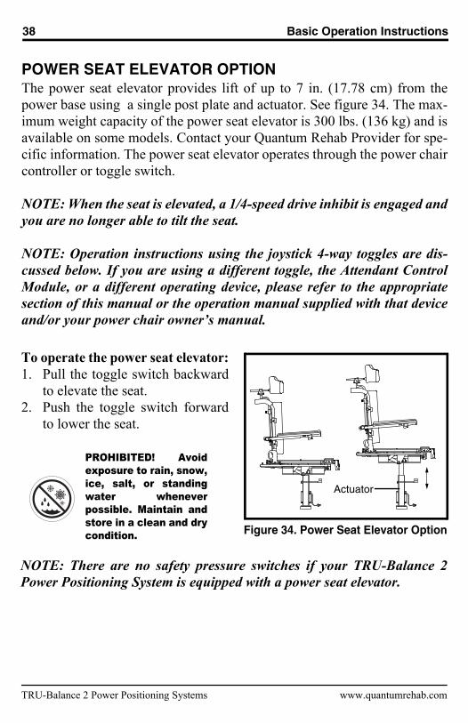
POWER SEAT ELEVATOR OPTIONThe power seat elevator provides lift of up to 7 in. (17.78 cm) from thepower base using a single post plate and actuator. See figure 34. The max-imum weight capacity of the power seat elevator is 300 lbs. (136 kg) and isavailable on some models. Contact your Quantum Rehab Provider for spe-cific information. The power seat elevator operates through the power chaircontroller or toggle switch.
NOTE: When the seat is elevated, a 1/4-speed drive inhibit is engaged andyou are no longer able to tilt the seat.
NOTE: Operation instructions using the joystick 4-way toggles are dis-cussed below. If you are using a different toggle, the Attendant ControlModule, or a different operating device, please refer to the appropriatesection of this manual or the operation manual supplied with that deviceand/or your power chair owner’s manual.
To operate the power seat elevator:
Figure 34. Power Seat Elevator Option
Actuator
1. Pull the toggle switch backwardto elevate the seat.
2. Push the toggle switch forwardto lower the seat.
PROHIBITED! Avoidexposure to rain, snow,ice, salt, or standingwater wheneverpossible. Maintain andstore in a clean and drycondition.
NOTE: There are no safety pressure switches if your TRU-Balance 2Power Positioning System is equipped with a power seat elevator.
TRU-Balance 2 Power Positioning Systems www.quantumrehab.com

Basic Operation Instructions 39
MANUAL RECLINE OPTION (TRU-BALANCE 2 POWERTILT ONLY)If your TRU-Balance 2 Power Positioning System includes Pride’s ManualRecline Option, you can adjust the seatback to angles ranging from the min-imum recline position (90° from the seat base) to the maximum recline posi-tion (180° from the seat base). See figure 35. When the seat is reclined past110°, the chair will be in full inhibit. Returning the seat to an angle of lessthan 110° degrees will restore power to the motors.
Recline Release Lever
Figure 35. Minimum and Maximum Recline Angles
WARNING! Never recline the seatback while the chair istilted. This could cause severe injury to the user. A safetyfeature will not allow you to tilt the seat while it is reclinedpast 110°. To reactivate the tilt feature, return the recliningseatback to an upright position.
To recline the seatback:1. Grasp the handles at the top of the seatback.2. Squeeze both of the recline release handles simultaneously, and position
the seatback to the desired angle. See figure 36.3. Release the handles to lock the seatback into position.
www.quantumrehab.com TRU-Balance 2 Power Positioning Systems

40 Basic Operation Instructions
Figure 36. Manual Recline Angle Adjustment
CARE AND MAINTENANCEMake sure all hardware is secured properly, but do not overtighten anyhardware.To clean the seating system, wipe it with a cloth dampened with mildsoap and water. Thoroughly dry the unit before using.
PROHIBITED! Avoid exposure to rain, snow, ice, salt, orstanding water whenever possible. Maintain and store in aclean and dry condition.
WARNING! Pride strongly recommends that you do not smokecigarettes while seated in your seating system although theseating system has passed the necessary testingrequirements for cigarette smoking. You must adhere to thefollowing safety guidelines if you decide to smoke cigaretteswhile seated in your seating system.
Do not leave lit cigarettes unattended. Keep ashtrays a safe distance from the seating system.Always make sure cigarettes are completely extinguishedbefore disposal.
WARRANTYThree-Year Limited WarrantyFor three (3) years from the date of purchase, Pride will repair or replace atour option to the original purchaser, free of charge, any of the followingparts found upon examination by an authorized representative of Pride to bedefective in material and/or workmanship:
Structural frame components
TRU-Balance 2 Power Positioning Systems www.quantumrehab.com

Basic Operation Instructions 41
Two-Year Limited WarrantyFor two (2) years from the date of purchase, Pride will repair or replace atour option to the original purchaser, free of charge, any of the followingparts found upon examination by an authorized representative of Pride to bedefective in material and/or workmanship:
Electronics
Eighteen-Month WarrantyFor eighteen (18) months from the date of purchase, Pride will repair orreplace at our option to the original purchaser, free of charge, any of thefollowing parts found upon examination by an authorized representative ofPride to be defective in material and/or workmanship:
Actuator
Warranty service can be performed by a Quantum Rehab Provider or byPride. Do not return faulty parts to Pride without prior consent. All transpor-tation costs and shipping damage incurred while submitting parts for repairor replacement are the responsibility of the original purchaser.
Warranty ExclusionsUpholstery and seatingRepairs and/or modifications made to any part without specific consentfrom PrideCircumstances beyond the control of PrideLabor, service calls, shipping, and other charges incurred for repair ofthe product, unless specifically authorized by Pride.
Damage caused by:Battery fluid spillage or leakageAbuse, misuse, accident, or negligenceImproper operation, maintenance, or storageCommercial use or use other than normal
There is no other express warranty.
www.quantumrehab.com TRU-Balance 2 Power Positioning Systems

TRU-Balance 2 Power Positioning Systems www.quantumrehab.com
42 Basic Operation Instructions
Implied warranties, including those of merchantability and fitness for a par-ticular purpose, are limited to one (1) year from the date of purchase and tothe extent permitted by law. Any and all implied warranties are excluded.This is the exclusive remedy. Liabilities for consequential damages underany and all warranties are excluded.
Some states do not allow limitations on how long an implied warranty lastsor do not allow the exclusion of limitation of incidental or consequentialdamages, so the above limitation or exclusion may not apply to you.
This warranty gives you specific rights, and you may also have other rightswhich vary from state to state.
Please fill out and return the product registration card to Pride MobilityProducts Corporation. This will aid Pride in providing the best possibletechnical and customer service.

www.quantumrehab.com TRU-Balance 2 Power Positioning Systems
N O T E S

*INFMANU3700*
www.pridemobility.com www.prideservice.com www.quantumrehab.com
Pride Mobility Products Corporation182 Susquehanna AvenueExeter, PA 18643-2694USA
Pride Mobility Products Company380 Vansickle Road Unit 350St. Catharines, Ontario L2R 6P7Canada
Pride Mobility Products Ltd.32 Wedgwood RoadBicester, Oxon OX26 4ULUK
Pride Mobility Products Australia Pty. Ltd.21 Healey RoadDandenong, 3175Victoria, Australia
Pride Mobility Products Italia S.r.l.Via del Progresso - ang. Via del LavoroLoc. Prato della Corte00065-Fiano Romano (RM)
Pride Mobility Products Europe B.V.Castricummer Werf 261901 RW CastricumThe Netherlands