basic mechanical properties of layered … · basic mechanical properties of layered steels ......
TRANSCRIPT

25
ACTA UNIVERSITATIS AGRICULTURAE ET SILVICULTURAE MENDELIANAE BRUNENSIS
Volume LXI 3 Number 1, 2013
http://dx.doi.org/10.11118/actaun201361010025
BASIC MECHANICAL PROPERTIES OF LAYERED STEELS
Michal Černý, Josef Filípek, Pavel Mazal, Petr Dostál
Received: September 18, 2012
Abstract
ČERNÝ MICHAL, FILÍPEK JOSEF, MAZAL PAVEL, DOSTÁL PETR: Basic mechanical properties of layered steels. Acta Universitatis Agriculturae et Silviculturae Mendelianae Brunensis, 2013, LXI, No. 1, pp. 25–38
This article deals with identifying attributes of layered steel materials (damask steel) with the help of mechanical tests. Experimentally verify basic mechanical properties of layered steel and subsequently assessed it in comparison with the values obtained for the classic steel materials. In conclusion, there are listed the possibilities of using multilayer steel materials in technical practice, depending on the economics of production.The damask steel was prepared by forge welding from a packet consisting of 17 layers (9 layers of tool steel 19 133 (ČSN) with the thickness of 6 mm and 8 layers 80NiCr11 steel in the form of saw bands with the thickness of 1.2 mm. The packet was cut into 8 parts, folded 3 times and forged together, which provided damask steel with 136 layers. The resulting steel bars were used to make semi-fi nished products with the approximate dimensions of the test specimens. For evaluation of mechanical properties were applied the following tests: tensile test, Charpy impact test, hardness and microhardness measurementsThe results of tests proved that the properties of damask steel are dependent not only on the direction led impact quality forge weld layers and content iof nhomogeneities in the place of discord, but also on the quenching and tempering temperature, resp. on the choice of quenching bath, which determine the fi nal structure of steel and the resulting hardness, respectively microhardness.
damask steel, mechanical properties of materials, tensile test, impact bending test, hardness tests
Layered steel Layered steel has been made since master
blacksmiths have tried to obtain material having the hardness of high carbon steel and at the same time the ductility of low and mild carbon steel. For centuries a historical set of empirical knowledge on selection of suitable input material, the course of forming, heat treatment and the fi nal treatment of the blade has been compiled.
The original structural “damask” was produced using a genuine technology when iron ore was melted in small clay and chemically closed crucibles (former Persia, India). The composition was always based on the traditional recipe of the blacksmith and kept strictly secret. The typical damask pattern was formed during cooling of steel in the crucible. Its highlighting was also supported by special forging. The specifi ed damask “variety” is referred
to as structural (crystalline, dendritic, etc.) damask and its pattern cannot be achieved by forge welding (Rudolf, 2010; Černý, 2011).
Welded DamascusFor the production of damask wrought forging
welding is used - the oldest method of steel welding. The metallic bond is due to the atomic structure where atoms of metallic elements have one, two, or three valence electrons. These electrons are not bound to any particular atom, they move freely in the chaotic movement between the positive ions of the metal atoms. As a result of their movement are shading electrostatic repulsive forces of positive ions. Electrons simultaneously serve as a binder that binds these ions. The basis of Damascus is the welding of two steel materials with low and high carbon content. Folding and forge welding packet of two diff erent qualities of steel in the form of plates,

26 Michal Černý, Josef Filípek, Pavel Mazal, Petr Dostál
it is possible to achieve a material which has the properties of both steels. O� en it can be achieved in this way the properties which surpass in many respects the attributes of the initial steel.
With increasing content of alloying steel loses its weldability. As suitable materials for welding is shown tool steel belonging to the carbon steel, vanadium, silicon and manganese. For the so� component are used steel grades 11, 12 (Czech standards), rarely other steel grades.
What are important are the welding temperature (approx. 1 300 °C) and the use of fl ux to dissolve scale. By folding non-homogeneous, but structurally regular material is produced. On each folding the number of layers increases by geometric progression. Each time the heating but the material oxidizes and decarburizes. This leads to a gradual homogenization of damask and degradation of its properties.
Note: More layers can be achieved by using a large number of plates in the initial packet or e.g. by its cutting into parts, subsequent folding and forging. Folding usually produces 100 to 500 layers. However, “micro-damask” is also produced with as many as thousands of layers.
Drawing of damasteel is infl uenced by a number of factors, such as the number of folds, the direction of folds, a way of processing the resulting rods (twisted – torsion bars (Fig. 2), drilling, grinding, etc.) and using a variety of semi-fi nished parts or tools (chain, steel wire rope, etc.). Drawing is clearly observable a� er grinding and etching. Also etching time can aff ect the resulting expressiveness drawings.
Currently, advocates machine bulk forming, especially in the production of steel sandwich of large dimensions. For its expensive production remain to Damascus and laminated materials in special and artistic production, and despite attempts to take advantage of these materials, such as agriculture (Černý, 2011).
1: Structural (crystallization) damask (Černý, 2011)
2: Example of drawing of torsion damask (Černý, 2011)
Basic mechanical properties of layered steels 27
Stainless damask steels (damasteels)Great progress was brought by the arrival of
powder metallurgy. If off ers joining of originally incompatible high-alloy steel types. The creativity of making the pattern is not limited in any way. You can design virtually any pattern (Fig. 3).
Mechanical propertiesThe material can be characterized in many ways
to diff erentiate their orientation to the area of use. It can be said that it has certain technical industry or consumer applications categorically expected properties. These attributes can be set with the help of specifi c tests. In one of the most important tests for technical tests are considered the mechanical properties of materials.
Properties of metallic materials are determined through tests specifi ed in standards (EN, ISO, ČSN, etc.). Properties of special materials (damask!) are determined through slightly modifi ed tests (sample shape, conditions, etc.).
Mechanical tests of materials are “de facto” verifi cation of their response to external stresses exerted. If the material is exposed to a force action, its reaction consists in internal tension unbalance. It may result in a deformation. A� er an elastic deformation as a reaction to an external load permanent (plastic) deformation occurs, which is manifested by a change of the geometry of the object that is made of the material? Within further increase of deformation manifestations as the consequence of an external force action the plastic deformation of the material structure continues and is terminated by failure of the atomic links of the internal structure of the material, which is generally referred to as fracture (Vojtěch, 2010).
If we consider the region of elastic deformation, the bond stress on the relative elongation the Hook law linear ( × = E [MPa], where E is the
Young’s modulus of elasticity). On the atomic level elastic (reversible) deformation is manifested as slight displacement of atoms from their balance position in the grid. When the external force ceases to act, the atoms return to the original positions.
Permanent (plastic) deformation in metallic materials can be achieved by gradual slipping of atomic planes due to tension. It is understood the mutual displacement of parts of the crystal along the slip plane motion of dislocations (lattice defects). Dislocations, resulting in solidifi cation of molten metal, or forming, the slip range by external stress. Since a violation occurs only bonds between atoms in the immediate vicinity of the moving dislocation, this violation of the basic crystal lattice energy relatively cheap (in comparison with the energy required to move the whole layer of atoms). Slip the easiest place in the crystal planes of atoms densely occupied (energy barrier decreases with the distance of atoms). For ease of slip in metals contributes to non-directional nature of metal binding (not subject to spatial charge or demands against mutual positions of atoms). For this reason the metals are capable of plastic deformation, depending on the type of crystal lattice (Vojtěch, 2010).
Tests of mechanical properties Antecedents of destructive and nondestructive
testing are given in the respective standards. This provides standardization and reproducibility of test results. Testing verifi es the functional characteristics of materials that guarantee resistance to external infl uences. In addition, you can determine its own structure state, frequency and occurrence of defects, etc. (Pohoda, 2005).
The basic destructive tests include: tensile test, compression test, impact bending test, hardness test, fatigue strength test, macroscopic and microscopic structure check, special tests.
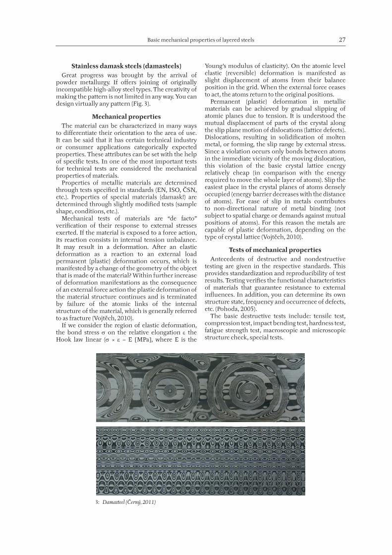
3: Damasteel (Černý, 2011)
28 Michal Černý, Josef Filípek, Pavel Mazal, Petr Dostál
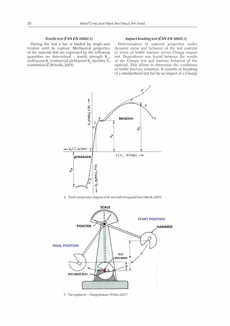
Tensile test (ČSN EN 10002-1)During the test a bar is loaded by single-axis
tension until its rupture. Mechanical properties of the material that are expressed by the following quantities are determined – tensile strength Rm, yield point Re, contractual yield point Rp, ductility A, contraction Z (Pohoda, 2005).
Impact bending test (ČSN EN 10045-1) Determination of material properties under
dynamic stress and behavior of the test material in terms of brittle fracture serves Charpy impact test. Dependence was found between the results of the Charpy test and fracture behavior of the material. This allows to determine the conditions of brittle fracture initiation. It consists in breaking of a standardized test bar by an impact of a Charpy
4: Tensile and pressure diagram of the steel with strong yield limit (Marek, 2009)
5: Test equipment – Charpy hammer (Věchet, 2007)
Basic mechanical properties of layered steels 29
hammer. The test bar may be smooth or with a notch. It is placed on two supports. The result of the test is impact energy [J]. With a smooth test bar the result is impact toughness while in the case of a notched object notch toughness is determined [J/cm2], i.e. the impact energy related to the initial cross-section of the specimen (under the notch). To draw a transition curve of impact energy on the temperature it is necessary to test impact test at various temperatures (Pohoda, 2005).
Hardness testsMaterial hardness represents the resistance to
penetration of a foreign body into the measured material. In technical practice developed static and dynamic methods of measuring hardness.a) Static measurement methods – forcing
an indenter into material using a force of a prescribed value. The indentation is converted to a hardness value. The Brinell, Rockwell and Vickers methods are used. The Vickers method can also be used for structural measurements (for individual grains, phases, surface layers, overlays, etc.), where if a lower load than 200 g is used, and the measurement is referred to as micro-hardness. The hardness value is expressed non-dimensionally in units depending on the applied method. (E.g. 56 HRC - Rockwell method, C – diamond cone and 150kg load).
b) Dynamic hardness tests – with a Poldi-hammer, Shore resilience test, etc. (Vojtěch, 2010; Pohoda, 2005).
EXPERIMENAL PART
Test specimensThe damask steel was prepared by forge welding
from a packet consisting of 17 layers (9 layers of tool steel 19 133 (ČSN) with the thickness of 6 mm and 8 layers 80NiCr11 steel in the form of saw bands
with the thickness of 1.2 mm. The packet was cut into 8 parts, folded 3 times and forged together, which provided damask steel with 136 layers. The resulting steel bars were used to make semi-fi nished products with the approximate dimensions of the test specimens.
Steel 19 133 is heat treatable steel that provides damask with hardness and wear resistance. For the “so� ” component 80NiCr11 steel was selected, which gives toughness to damask. Thanks to its resistance to etching the 80NiCr11 steel appears as the light component in the resulting structure. This is steel with high hardenability for abrasion-resistant and elastic tools.
Steel 80NiCr11 (equivalent according to the steel 19 615 - CSN) is due to resistance to etching of the resulting structure as light excel folder. It is a steel alloy with a high hardenability, usable for fl exible wear resistant tools.
Test specimens for Charpy impact bending test were made of forged Damascus rods with dimensions of 13 × 13 mm. Followed by cutting the length 60 mm, grinding on the belt sander to a normalized dimensions of 10 × 10 × 55 mm and applying of protective coating (protection against decarburization – TINDEREX K-12124) samples were prepared for heat treatment. To achieve the authenticity of behavior of the cutting tool the samples were made without notches. The samples were used to test hardness according to Rockwell. The casting was made into oil and water bath (Jech, 1983).
Indicative tensile test – forged damask strips were ground and then laser was used to cut them into specimens for the tensile test with the measured length of 60 mm and width of 10 mm. Hardening in accordance with (Jech, 1983) – 900 ºC/oil, water/ 30 minutes, tempering –150, or 350 ºC/15 minutes.
Note: To protect the clamping surfaces from hardening the method inspired by hardening of Japanese swords was selected – applying clayey material mixed with protective
I: Chemical composition of steel 19 133 (Czech standard)
Chemical composition [%]
C Mn Si P S Cr Ni
0,65–0,75 0,20–0,45 0,15–0,35 max 0,035 max 0,035 max0,25 max 0,25
II: 2 Chemical composition of steel 80NiCr11
Chemical composition [%]
C Mn Si Cr Ni S
0,74–0,8 0,25–0,6 do 0,4 0,2–0,5 2,4–2,9 0,025
III: Heat treatment of test specimens for Charpy test
Quenching medium Quenching temperature Tempering temperature
Interval Interval
water 870 ºC 30 min. 150 ºC 350 ºC 15 min.
oil 900 ºC 30 min. 150 ºC 350 ºC 15 min.
30 Michal Černý, Josef Filípek, Pavel Mazal, Petr Dostál
coating against decarburization on the clamping surfaces of the test specimen. A� er hardening the hardness values of the clamping surfaces of the test specimens did not exceed 23 HRC!
Charpy impact testFor the purpose of the test was used pendulum
hammer. The specimen was placed on the support surface, which are fi rmly bolted to the body of casted stand. The test is successful if the sample is broken. If the sample is too tough to stop ram hammer (!), the value cannot be deducted.
To achieve the authenticity the unnotched samples were chosen and impact strength of material was measured. Only samples hardened in oil and tempered at 150 ºC and 350 ºC were made with a U notch because they failed to break the no tempered bend test specimens quenched in oil. It could be concluded that even a� er tempering sample cannot be without a notch thanks to great strength can break the chair.
Tensile testTensile test was performed only for orientation on
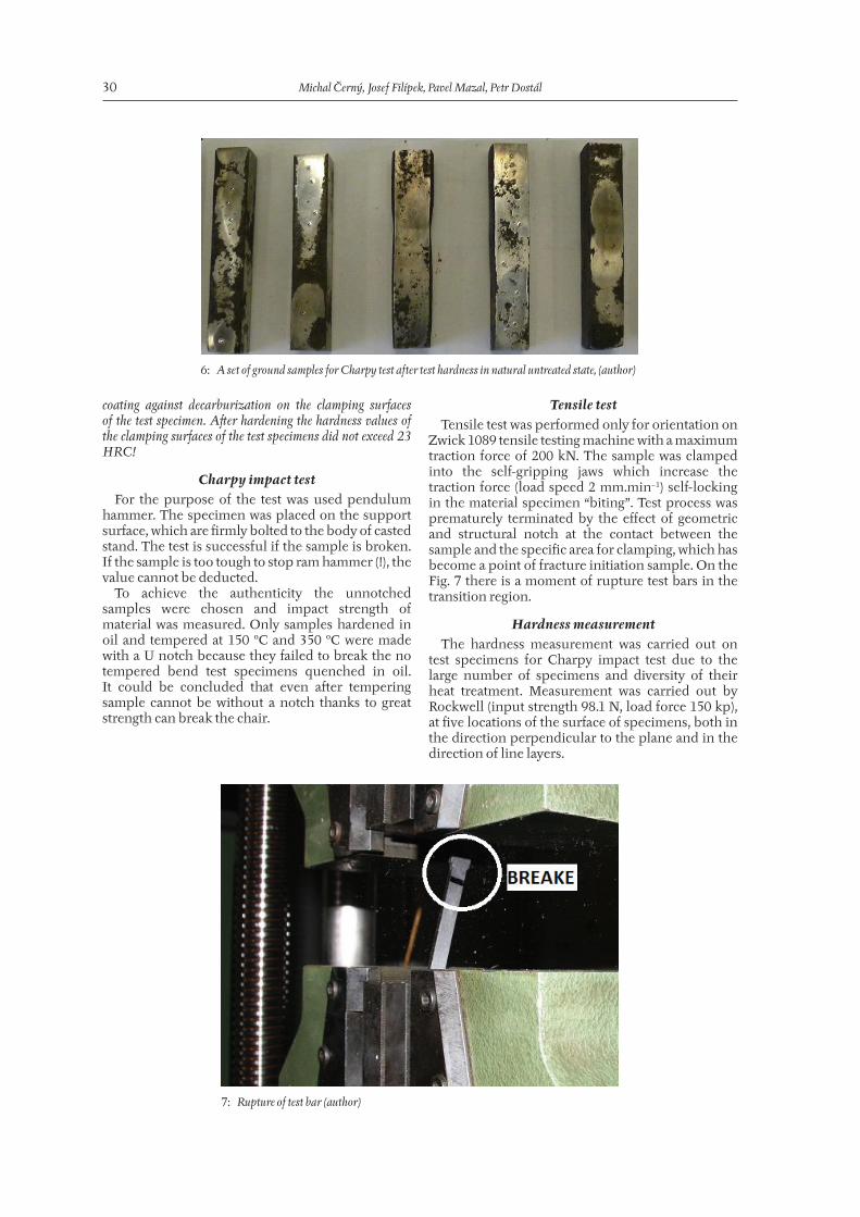
Zwick 1089 tensile testing machine with a maximum traction force of 200 kN. The sample was clamped into the self-gripping jaws which increase the traction force (load speed 2 mm.min−1) self-locking in the material specimen “biting”. Test process was prematurely terminated by the eff ect of geometric and structural notch at the contact between the sample and the specifi c area for clamping, which has become a point of fracture initiation sample. On the Fig. 7 there is a moment of rupture test bars in the transition region.
Hardness measurement The hardness measurement was carried out on
test specimens for Charpy impact test due to the large number of specimens and diversity of their heat treatment. Measurement was carried out by Rockwell (input strength 98.1 N, load force 150 kp), at fi ve locations of the surface of specimens, both in the direction perpendicular to the plane and in the direction of line layers.
6: A set of ground samples for Charpy test after test hardness in natural untreated state, (author)
7: Rupture of test bar (author)

Basic mechanical properties of layered steels 31
Metallographic observations and microhardness measurement
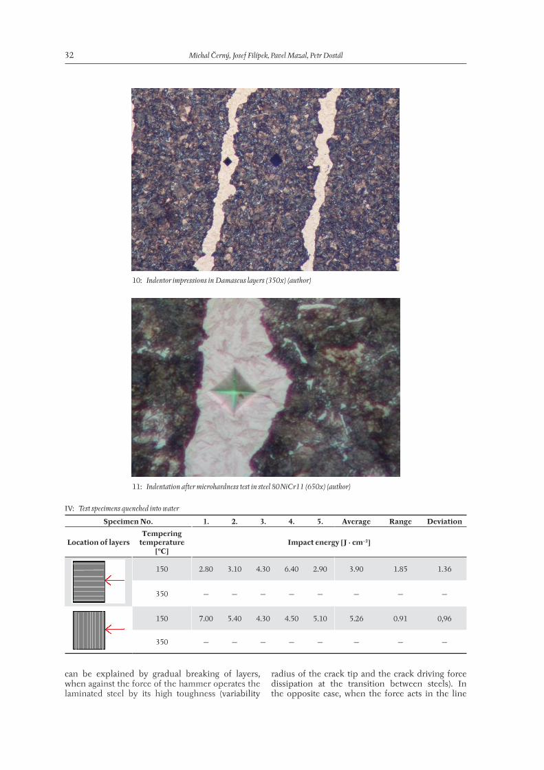
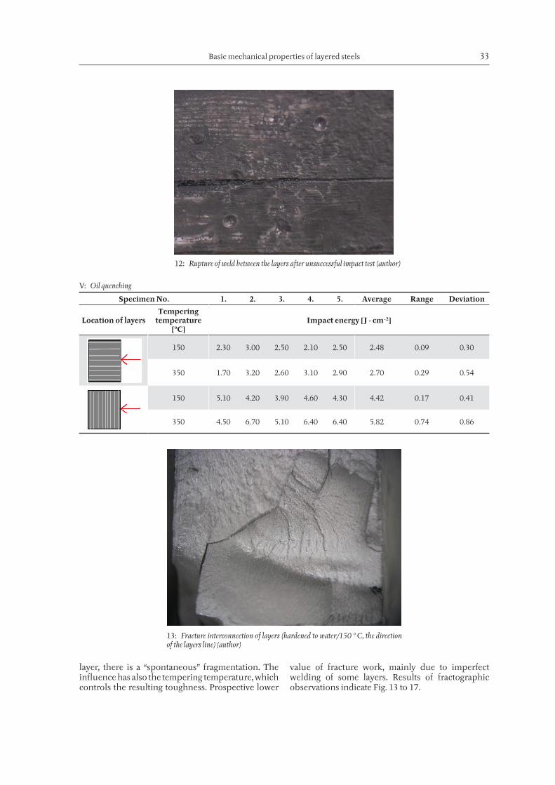
Microhardness measurement was preceded by metallographic observation at the magnifi cation of 350x and 650x. A Hanneman microhardness tester was used (analogous to the Vickers method) and the hardness of individual layers was measured. The indenter is a diamond pyramid whose indentation (Fig. 10) is found in the structure of tempered martensite (dark layer – steel 19133 – ČSN) and in martensitic needles with secondary cementite – white layer – 80NiCr11 steel (Fig. 11).
“Micro-indentations” of the indenter were located directly in individual layers of both the steel types and the measured hardness exhibits higher hardness values here than the macro-hardness measurement (consequence of the absence of plastic deformation around the micro-indentation). Thus, hardness is measured in the direction that is decisive e.g. for the tool blade edge (i.e. along the layer line), but a� er conversion from the Vickers scale to the Rockwell scale the micro-hardness value is too high - up to 68 (see Tab. IV).
Measurements – discussion of results
Impact tests It was used a total of 40 samples (8 sets of 5
samples). Intentions was to determine the infl uence of quenching and subsequent tempering the resulting toughness, impact orientation layering of material and its resistance to impact in a line perpendicular to the layers and surface layers. For samples quenched in water (Tab. IV) was tested impact resistance, for large values of hardness and lower toughness and it was not necessary fabrication notch. For samples quenched in oil (or non-tempered sample was not broken!) had to be sanded U-notch.
Samples quenched in water and tempered at 350 °C by increasing the withstand impact toughness for delaminating of layers (Fig. 12).
From the above it is clear layering eff ect on the fi nal strength of the material for samples quenched in water and in oil. In the case that the impact was conducted in the line layer, the material reached a lower toughness than when impact force acted perpendicular to the line layer. This phenomenon
8: Indentor impression of hardness measurement (HRC) in the direction of line layers (author)
9: Indentor impressions of hardness measurement (HRC) in the direction perpendicular to the surface layers (author)
32 Michal Černý, Josef Filípek, Pavel Mazal, Petr Dostál
can be explained by gradual breaking of layers, when against the force of the hammer operates the laminated steel by its high toughness (variability
radius of the crack tip and the crack driving force dissipation at the transition between steels). In the opposite case, when the force acts in the line
10: Indentor impressions in Damascus layers (350x) (author)
11: Indentation after microhardness test in steel 80NiCr11 (650x) (author)
IV: Test specimens quenched into water
Specimen No. 1. 2. 3. 4. 5. Average Range Deviation
Location of layersTempering
temperature [ºC]
Impact energy [J · cm−2]
150 2.80 3.10 4.30 6.40 2.90 3.90 1.85 1.36
350 — — — — — — — —
150 7.00 5.40 4.30 4.50 5.10 5.26 0.91 0,96
350 — — — — — — — —
Basic mechanical properties of layered steels 33
layer, there is a “spontaneous” fragmentation. The infl uence has also the tempering temperature, which controls the resulting toughness. Prospective lower
value of fracture work, mainly due to imperfect welding of some layers. Results of fractographic observations indicate Fig. 13 to 17.
12: Rupture of weld between the layers after unsuccessful impact test (author)
V: Oil quenching
Specimen No. 1. 2. 3. 4. 5. Average Range Deviation
Location of layersTempering
temperature [ºC]
Impact energy [J · cm−2]
150 2.30 3.00 2.50 2.10 2.50 2.48 0.09 0.30
350 1.70 3.20 2.60 3.10 2.90 2.70 0.29 0.54
150 5.10 4.20 3.90 4.60 4.30 4.42 0.17 0.41
350 4.50 6.70 5.10 6.40 6.40 5.82 0.74 0.86
13: Fracture interconnection of layers (hardened to water/150 º C, the direction of the layers line) (author)

34 Michal Černý, Josef Filípek, Pavel Mazal, Petr Dostál
Tensile testsTypical results of the tensile test are summarized
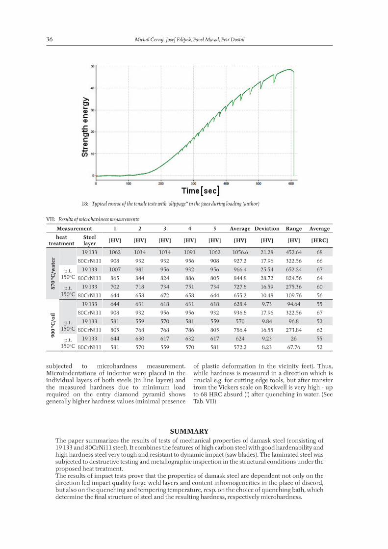
in Tab. VI (Rp0,2 – proof stress, Rfr – fracture limit)Fig. 18 shows a gradual jams and shi� s of
specimen in the jaws. Real tensile strength Rm failed to fi nd, since the fragmentation of the specimen occurred due to insuffi cient radius in the transition and changes in body structure also in the specifi c length of rod and clamping in all cases (!).
Hardness measurementSteel hardness a� er quenching in water is moved
in the direction of a line of layers in the range of 53 to 56 HRC and was mainly infl uenced by the random location of the measured place due to the presence of so� and harder layers of steel. Values
measured perpendicular to the layers (52-54 HRC) were also aff ected by the presence of the upper layer of steel from steel 19 133 (CSN). A� er subsequent tempering at 150 °C was observed a decrease in hardness in the direction of line layers as well as in the direction of perpendicular by about 1-3 HRC. When tempering at 350 °C for about 7-8 HRC. A� er quenching in oil Damascus steel reached hardness only 39-40 HRC, but a� er tempering the hardness decrease was already signifi cant, only about 1 HRC in a line of layers and 4 HRC units measured in a plane coplanar with layers of damask, i.e. in the fi rst upper plane.
Microhardness measurementTo determine the microhardness the samples
of Damascus steel a� er all heat treatments were
14: Delaminating at the weld (water/150ºC, the force perpendicular to the plane of layers) (author)
15: Initiation of fracture from notch with a visible contraction of the sample perpendicular to the direction of crack propagation (oil/150 ºC, the direction of impact in layers line) (author)
Basic mechanical properties of layered steels 35
16: Transgranular and intergranular impact fracture on fission in line damask layers (oil / 350 ºC) (author)
17: Fracture between layers of steel (oil / 350 ºC, shock led perpendicularly to the layers) (author)
VI: Results of tensile tests
Sample No. Rp0,2 Rm Rfr A B t v
[MPa] [mm] [sec] [mm]
1 876.56 1264.75 1215.48 3.84 9.98 612 2
2 876.45 1169.52 1134.57 3.77 10.28 365 2
3 880.08 1262.8 1193.02 3.77 10.08 395 2
36 Michal Černý, Josef Filípek, Pavel Mazal, Petr Dostál
subjected to microhardness measurement. Microindentations of indentor were placed in the individual layers of both steels (in line layers) and the measured hardness due to minimum load required on the entry diamond pyramid shows generally higher hardness values (minimal presence
of plastic deformation in the vicinity feet). Thus, while hardness is measured in a direction which is crucial e.g. for cutting edge tools, but a� er transfer from the Vickers scale on Rockvell is very high - up to 68 HRC absurd (!) a� er quenching in water. (See Tab. VII).
18: Typical course of the tensile tests with “slippage” in the jaws during loading (author)
VII: Results of microhardness measurements
Measurement 1 2 3 4 5 Average Deviation Range Average
heat treatment
Steel layer [HV] [HV] [HV] [HV] [HV] [HV] [HV] [HV] [HRC]
870
ºC/w
ater
19 133 1062 1034 1034 1091 1062 1056.6 21.28 452.64 68
80CrNi11 908 932 932 956 908 927.2 17.96 322.56 66
p.t. 150ºC
19 133 1007 981 956 932 956 966.4 25.54 652.24 67
80CrNi11 865 844 824 886 805 844.8 28.72 824.56 64
p.t. 350ºC
19 133 702 718 734 751 734 727.8 16.59 275.36 60
80CrNi11 644 658 672 658 644 655.2 10.48 109.76 56
900
ºC/o
il
19 133 644 631 618 631 618 628.4 9.73 94.64 55
80CrNi11 908 932 956 956 932 936.8 17.96 322.56 67
p.t. 150ºC
19 133 581 559 570 581 559 570 9.84 96.8 52
80CrNi11 805 768 768 786 805 786.4 16.55 273.84 62
p.t. 350ºC
19 133 644 630 617 632 617 624 9.23 26 55
80CrNi11 581 570 559 570 581 572.2 8.23 67.76 52
SUMMARY The paper summarizes the results of tests of mechanical properties of damask steel (consisting of 19 133 and 80CrNi11 steel). It combines the features of high carbon steel with good hardenability and high hardness steel very tough and resistant to dynamic impact (saw blades). The laminated steel was subjected to destructive testing and metallographic inspection in the structural conditions under the proposed heat treatment. The results of impact tests prove that the properties of damask steel are dependent not only on the direction led impact quality forge weld layers and content inhomogeneities in the place of discord, but also on the quenching and tempering temperature, resp. on the choice of quenching bath, which determine the fi nal structure of steel and the resulting hardness, respectively microhardness.

Basic mechanical properties of layered steels 37
Toughness measured in the direction of line layers is benefi cial in practice from the viewpoint of the dynamic impact of a tool made from this material (cutting tools). Much more signifi cant (up to 6.4 J.cm−2) appears to be resistance in the direction perpendicular to the layers, which limit its application even in the dynamic bending stress and torque (torsion). This is one of the most important properties of damask steel.It follows that the ideal temperature tempering a� er quenching in water from a temperature of 870 °C, the temperature is being referred to 350 °C. For such heat-treated sample is required for the successful implementation of Charpy notch test prepare a test and measure and notch toughness. If used oil quenching, it is always necessary to hone the U-notch in order to break the chair comp. Here, too, showed the infl uence of tempering temperature on the work required to shi� the sample. Using high temperature tempering steel loses hardness. Since tempering at 150 °C reaches high values impact work, it would be advisable to choose a� er oil hardening vote tempering temperature only around 150 ºC. Select the type of quenching and tempering temperatures are therefore linked with the required mechanical properties, which are expected from the material for use damask steel and leads to the maximum tool life of this material.To approximate tensile test were used test bar of rectangular profi le. The results show that in the test samples it is necessary to use a larger radius of curvature in the transition between the specifi c length and the clamping surface of the specimen that would not act as a high-strength material construction notch. Attention is also necessary to pay to structural gradual transition (transition between the turbid structure and non-turbid) and thereby also eliminating the structural notch. But even for samples with a small transition radius values were for uniaxial tension Rp0, 2 – 878 MPa and Rm – 1 200 MPa (for dependency – with a weak yield strength) that their ratio ¾ demonstrate the ability of steel accumulate during growth voltage, signifi cant deformation prior to fi nal fragmentation body.Measurement of hardness (54-56 HRC) and microhardness (52-66 HRC) defi nes the application of damask steel for production of machine tools with medium hardness. However, given the toughness test application can sort Damascus steel in the production of tools with the highest durability.
Acknowledgement
The research has been supported by the project IP 10/2010 „Proportional monitoring of the Acoustic emission in crypto-conditions“, fi nanced by internal grant agency (IGA) Mendel University in Brno, Faculty of Agronomy. Above mentioned results were created also as a part of solution of the project MPO CR FR-TI1/371 „Integrated system of monitoring of selected machine parts“ and supported by European Regional Development Fund in the framework of the research project NETME Centre under the Operational Programme Research and Development for Innovation (reg. No. CZ. 1.05/2.1.00/01.0002).
REFERENCESJECH, J., 1983: Tepelné zpracování oceli. SNTL –
Nakladatelství technické literatury, Praha, vyd. 1., 392 s.
RUDOLF, T., 2010: Damašková ocel. bakalářská práce, MENDELU Brno.
ČERNÝ, M., 2011: Materiály pro výrobu nožů. [online]. [citace 2011-11-05]. URL: <http://www.noze-nuz.com>.
ČERNÝ, M., ČECHLOVSKÝ, S., 2011: Povídání o damaškové a vrstvené oceli I. a II. [online]. [citace 2011-11-06]. URL: <http://www.noze-nuz.com>.
VOJTĚCH, D., 2010: Materiály a jejich mezní stavy. VŠCHT, Praha, 212 s., ISBN 978-80-7080-741-5.
POHODA, J., 2005: Destruktivní zkoušení základních materiálů a svarových spojů. TDS Brno – SMS, Brno, 97 s.
VĚCHET, S., 2010: Mechanické vlastnosti a charakteristiky materiálů I. [online]. [citace 2012-01-01]. URL: <ime.fme.vutbr.cz/Files/Vyuka/BUM/02-BUM.ppt>.
MAREK, K., 2009: Vlastnosti materiálů – pružnost, pevnost. [online]. [citace 2012-02-08]. URL: <http://www.strojirenstvi.wz.cz/stt/rocnik1/06a_pruznost_pevnost.php>.
DOHNAL P., KOUDELKA J., 2011: Wootz/Bulat…[online]. [citace 2012-01-15]. URL: <http://www.dohnalknives.com/strana01cz.htm>.
BOLF, P., 2012: Detail nůž (11–19). [online]. [citace 2012-02-12]. URL: <http://jswords.com/11-19_d.php>.
BOLF, P., 2012: Detail katana (10–11). [online]. [citace 2012-02-12]. URL: <http://jswords.com/10-11_d.php>.
Candart knifes. [online]. [citace 2012-02-18]. URL: <http://www.crandart.co.uk/>.
HURNÍK Z., 1995: Samurajský meč. Naše vojsko, Praha, 155 s. ISBN 80-206-0510-X.
JOHNSON J., (2010) Cord-wrapped San Mai. [online]. [citace 2012-02-25]. URL: http://www.jeridjohnson.com/index.php?option=com_content&task=view&id=65&Itemid=54.

38 Michal Černý, Josef Filípek, Pavel Mazal, Petr Dostál
DOSTÁL P.,2011: Korozní a napěťová degradace Al-Mg slitin. Disertační práce, MENDELU Brno.
Zkouška tvrdosti podle Vickerse. [online]. [citace 2012-03-16]. URL: <http://cs.wikipedia.org/wiki/Zkou-%C5%A1ka_tvrdosti_podle_Vickerse>.
Fyzikální základy vědy o materiálu. [online]. [citace 2012-04-1]. URL: <http://www.ped.muni.cz/wphy /fyzvla/index.htm>.
Address
doc. Ing. Michal Černý, CSc., doc. Ing. Josef Filípek, CSc., Ing. et Ing. Petr Dostál, Ph.D., Department of Engineering and Automobile Transport, Mendel University in Brno, Zemědělská 1, 613 00 Brno, Czech Republic, doc. Ing. Pavel Mazal, CSc., Institut of Machine and Industrial Design, University of Technology Brno, Technická 2, 616 69 Brno, Czech Republic, e-mail: [email protected], [email protected]