basic machines and how they’ work - … · basic machines and how they’ work prepared by bureau...
TRANSCRIPT
BASIC MACHINES
AND HOW THEY’ WORK
Prepared by Bureau of
Naval Personnel
Dover Publications, Inc.
New York
Published in Canada by Gemml Publishing Com- pany, Ltd., 30 Lesmill Road, Don Mills, Toronto, Ontario.
Published in the United Kingdom by Constable and Company, Ltd., 10 Orange Street, London WC 2.
This Dover edition, lint published in 1971, is an ilnabridged and unaltered republication of the work originally published by the United States Government Printing Office in 1965, under the title: Basic Machines. This work was prepared by the Bureau of Naval Personnel, Department of the Navy, as Navy Training Course NAVPERS 10624.A.
t*.imaiiwzoi Standard Book Number: O-486-21709-4 Library of Congress Catalog Cord Number: 77.153739
Manufactured in the Uniti States of America Dover Publications, Inc.
180 vatick street New Yodi, N. Y. 10014
PREFACE
Basic Machines is written as a reference far the enlisted men in the Navy whose duties require knowledge of the fundamentals of machinery.
Beginning with the sim&_t .,i machines-the lever-the book proceeds with tiie discussicn of block and tackle, w!xel and axle, inclined plane, screw and gears. It explains the concepts of work and #aver, and dif- ferentiates between the terms “force” and “pressure, ” The fundamentals of hydznstatic and hydraulic mechanisms are discussed in detail. The final chapters include several examples of the combination of simple mechanisms to make complex machines.
As one of several basic Navy Training Courses, this book was p-- pared by the Education and Training Support Service, Washington, D. C., far the Chief of Naval Personnel.
CONTENTS
CHAPTER Page
1.
2.
3.
4.
5.
6.
7.
8.
9.
10.
11.
12.
13.
14.
15.
Levers .......................
Block and Tackle .................
The Wheel and Axle ...............
The Inclined Plane and Wedge. ........
The Screw .....................
c&i-s. ........................
Work .........................
-r,.wr ........................
Force afid Pressure ..............
Hydrostatic and Hydraulic Machines ...
Machine Elements and Basic Mechanisms
Complex ?&whines ................
Internal Combustion Engine .........
Power Trains ..................
Basic Computer Mechanisms .........
.
. . .
~
.
. .
1
10
16
23
26
30
39
46
50
56
69
87
106
130
150
NDEX......................................... 158
vii
CREDITS
Source
Underwood Corporation
iJ. S. Naval Institute: Naval Auxiliary Machinery
Naval Turbines
. ““l
Figures
Figure 12-4 through Figure 12-16
Pigure Q-6 Figure 11-2
CHAPTER 1
LEVERS
YOUR HELPERS
Ships have evolved through the ages from crude rafts to the huge complex cruisers and carriers of today’s Navy. It was a long step from oars to sails, and another long step from sails to steam. With today’s modern nuclear- powered ships another long step has beentaken. Each step in the progress of shipbuilding has in- volved the use of more and more machines, until today’s Navy men are specialists in operating and maintatning machinery. TheBoatswainoperates the winches to hoist cargo and the anchor; the men in the engine room operate pumps, valves, generators, and other machines to produce and
,, control the ship’s power; men in the weapons department operate shell hoist, and rammers; elevate and train thegunsandmissilelaunchers; the cooks operate mixers and can openers; men in the CB rates drive trucks, operate cranes, graders, and bulldozers. In fact it is safe to say every rate in the Navy uses machinery some time during the day’s work.
Each machine used aboard ship has made the physical work load of the crew lighter. You don’t walk the capstan to raise the anchor, or heave on a line to sling cargo aboard. Ma- chines have taken over these jobs, and have simplllied and made countless others easier. Machines are your friends. They have taken much of the backscbe sod drudgery out of a sailor’s life. Reading this book should help you recoguixe and uuderstand the operations of many of the machines 9ou see about you.
WI&T IS A MACHINK?
A5 you look you, you probably see half a dozen mxhtnes that you don’t recognize as such. Ordinarily you think of a machine au a complex devtce-a gasoline engine or a tgpevriter. They are machinea, but M) is a
hammer, a screwdriver, a ship’s wheel. A machine is any device that helps you to do work. It ‘may help by changing the amount of the force or the speed of action. For example, a claw hammer is a machine-you can use it to apply a large force for pulling out a nail. A relatively small pull on the handle produces a much greater force at the claws.
We use machines to TRANSFORM energy. For example, a generator transforms me- chanical energy into electrical energy. We use machines to TRANSFER energy from one place to another. For example, the connecting rods, crankshaft, drive shaft, and rear axle transfer energy from the automobile engine to the rear wheels.
Another use of machines is to MULTIPLY FORCE. We use a svstem of oullevs (a chain hoist for example) to lift a heavy road. The pulley system enables us to raise the load by exerting a force which is smaller than the weight of the load. We must exert this force over a greater distance than the height through which the load is raised; thus, the load moves more slowly than the chain on which we pull. A machine enables us to gain force, but only at the expense of speed.
Machines may also be used to MULTIPLY SPEED. The best example of this is the bicycle, by which we gain speed by exerting a greater force.
Machines are also used to CHANGE THE DI- RECTION OF A FORCE. For example, the signalman’s halyard enables one end of the line to exert an uuward force on a sisnal flag as a downward fdrce is exerted on the other end.
There are only six simple machines-the LEVER, the BLOCK, the WHEEL a.dAXLE, the INCLINED PLANE, the SCREW, and the GEAR. However. uhvsiciste reccumlze that there are only two bask! prlnclples I% machines; namely, the lever and the inclined plane. The wheel and
1
BASIC MACHINES
axle, the block and tackle, and gears may be considered levers. The we.lge and the screw use the principle of the inclined plane.
When you are familiar with the principles of these simple machines, you can readily understand the operation of complex machines. Complex machines are merely combinations of two or more simple machines.
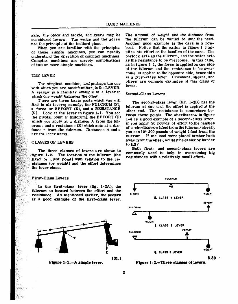
TIIE LEVER
The simplest machine, and perhaps the one with which you are most familiar, isthe LEVER. A seasaw is a familiar example of a lever in which one weight balances the other.
There are three basic parts which you will find in all levers; namely. the FULCRUM (F), a force or EFFORT (El, and a RESISTANCE CR). Look at the lever in figure 1-1. You see ihe pivotal point F (fulcrum); the EFFORT (El which you apply at a distance A from the +~l- crum; and a resistance (R) which acts at a dis- tance a from the fulcrum. Distances A and a are thr le-er arms.
CLASSES OF LEVERS
The three classes of levers a,re shown in fiire 1-2. The location of the fulcrum (the ,fixed or pivot point) with relation to the re- sistance (or weight) and the effort determines the lever class.
First-Class Levers
In the first-class lever (fig. LWL), the fulcrum is located Setcseen the effort and the reststance. As mentioned earlier, the seesaw is a good exampIe of the ftret-class lever.
F@ure 1-L-A simple lever. 131. .l
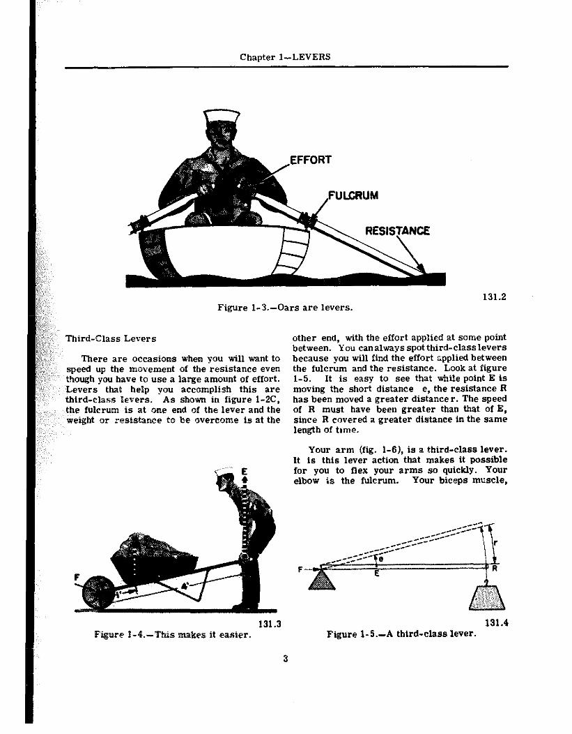
The amount of weight and the distance from the fulcrum can be varied to suit the need. Another good example is the oars in a row- boat. Notice that the sailor in figure l-3 ap- plies his effort on the handles of the oars. The oarlock acts as the fulcrum, and the water acts as the resistance to be overcome. In this case, as in figure l-l, the force isappliedon one side of the fulcrum and the resistance to be over- come is applied to the opposite side, hence this is a first-class lever. Crowbars, shears, and pliers are common examples of this class of lever.
Second-Class Levers
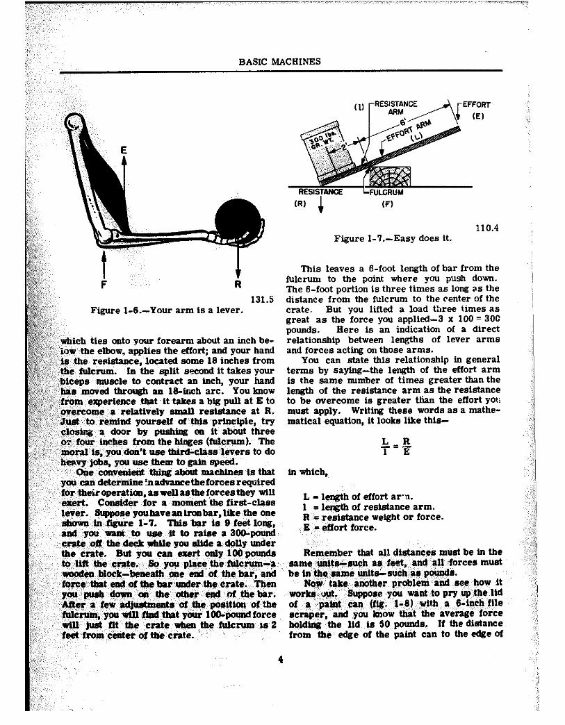
The second-class lever (fig. 1-2B) has the fulcrums at one end; the effort is applied at the other end. The resistance is somewhere be- tween these points. The wheelbarrow in figure 1-4 is a good example of a second-class lever. if you appljj 50 pounds of effort to.the handles of a wheelbarrow 4 feet from the fulcrum (wheel), you can lift 200 pounds of weight 1 foot from the fulcrum. If the load were placed farther back away from the wheel, would it be easier or harder to lift?
Both first- and second-class levers are commonly used to help in overcoming big resistances with a relatively small effort.
FULCRUM
A EFFcm WElSHl
L. CLASS 1 LEVER
ECFom
FULCRVY
A t
YElG"T 1. CLASS 2 LEVER
Fv- ermw e. CLAU a LCVCR
5.30 Flguro l-S.-Three classes of lsverr.
3
Chapter l-LEVERS
,~,,,,, ,,,,,,
::i:,,,,
!$,,Z,@ 131.2 Figure I-3.-Oars are levers.
pr::,
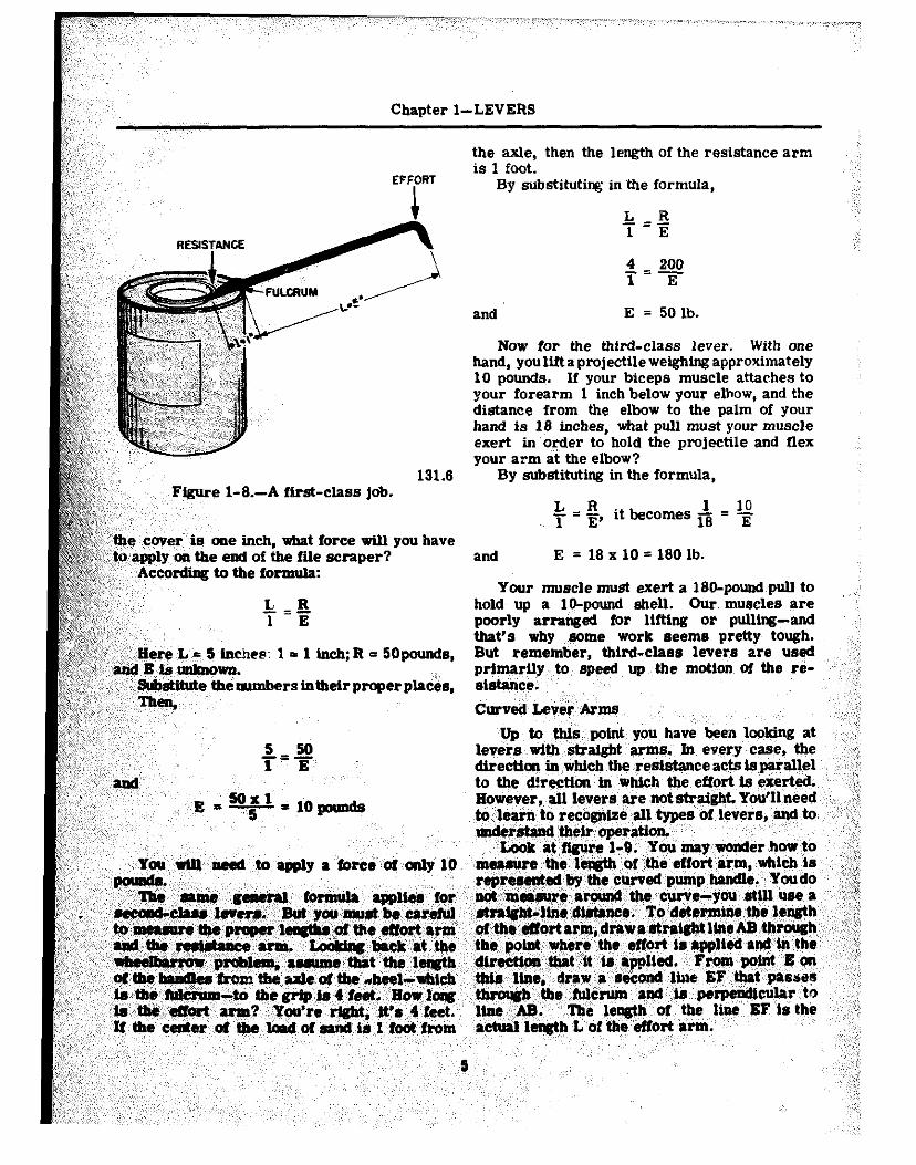
Third-Class Levers other end, with the effort applied at some point I~%;& ~,~:@~ between. You can always spot third-class levers :>>:,f ;t;;y,:,; :’ There are occasions when you will want to because you will find the effort applied between
,, speed up the movement of the resistance even the fulcrum and the resistance. Look at figure ,,,:, ,, ,’ though you have to use a large amount of effort. l-5. It is easy to see that while point E is
Levers that help you accomplish this are moving the short distance e, the resistance R third-class levers. As shown in figure 1-2C, has been moved a greater distance r. The speed the fulcrum is at one end of the lever and the of R must have been greater than that of E, weight or resistance to be overcome is at the since R covered a greater distance in the same
length of time.
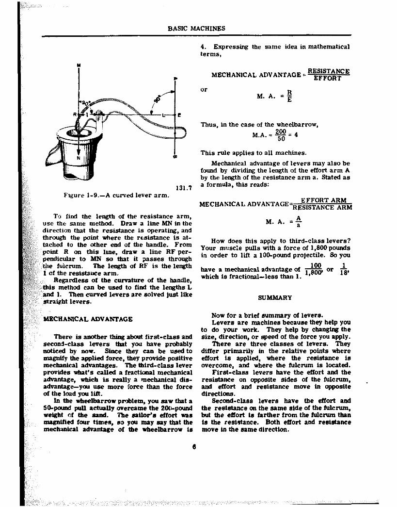
Your arm (fig. l-61, is a third-class lever. It is this lever action that makes it possible for you to flex your arms so quickly. Your elbow is the fulcrum. Your biceps muscle,
F
131.3 131.4 kes it easier. Figure 1-5.-A third-class lever.
3
BASIC MACHINES
Figure I-6.-Your arm is a lever.
effort; and your hand some 16 inches from
SabtgpullatEto resbtance at R.
yoursel( of thts principle, try by pu6htng on it about three
from the hiages MuImyum). The ‘t use third-cIass levers to do
4
(RI (F)
Figure l-7.-Easy does it. 110.4
This leaves a B-foot length of bar from the fulcrum to the point where you pnsh down. The B-foot portion is three times as long as the distance from the fulcrum to the renter of the crate. But you lifted a load three times as great as the force you applied-3 x 100 = 300 pounds. Here is an indication of a direct relationship between lengths of lever arms and forces acting on those arms.
You can state this relationship in general terms by saying-the length of the effort arm is the same rmmber of times greater than the length of the resistance arm as the resistance to be overcome is greater than the effort yorl must apply. Writing these words as a mathe- matical equation, it looks like this-
L-R -_- 1 E
in which,
L = ler&h of effort arx. 1 =, le@tb of resistance arm. R’= resistance weight or force.
,, E = effort force.
Remember that all distances must be in the 66me ,<&nrch as ,feet, +nd all, forces mud be In the.clame, untt6&3Ucb~~a6~pound6.
Now, kik6, another problem’tind 680 how it work6 wt. ,6uppore y,ou ‘tint to pry up t,he lid of ,P’ paM can, (f@. f-,8) ,:wtth 6 84nch,file remper, and yti know that the average force holdtng ,the ,lld, ,t6 50 pounds. If the distance from the edge of the patat can to the edge of
Chapter l-LEVERS
the axle, then the length of the resistance arm is 1 foot.
EFFPRT By substituting in ‘the formula,
~~~~~:~~ e cover is one ineb, what force will you have
&&p, apply 011 the end of the file scraper?
-=E L 1 E
and E = 50 lb.
Now for the third-class lever. With one hand, youliftaprojectile weighing approximately 10 pounds. If your biceps muscle attaches to your forearm 1 inch below your elbow, and the distance from the elbow to the palm of your hand is 18 inches, what pull must your muscle exert in ‘order to hold the projectile and flex your arm at the elbow?
By substituting in the formula,
L=Il. it&comes1 = lo 1 E’ 18 E
and E = 18 x 10 = 180 lb.
Your muscle must exert a 180-pmuu~pull to hold up a lo-pound shell. Our muecles are poorly arranged for lifting or pulling-and that’s why ,~~rne work Seems pretty tough. But remember, third-class lever6 are u6ed prlmarfly to 6peed up the motion of the re- 6iEt6nC6.
curved Lever Arms
Up to this point ,you have been looking at le9er6 witb 6traight 6rm6. In, every case, the direction i6 which th6 resistance act6 i6 ps@lel to the d!rection in which the effqrt t6 exerted. I Eowever, all levere, qre not straight. You’ll need’ 4 ,jo Je6in to recog&i all,types ‘of,le+er6,‘6+ to l6ld4irM their oaeratbJn.
BASIC MACHINES
RESISTANCE
i
MECliANlCAL ADVANTAGE = EFFORT
or
4. Expressing the same idea in mathematical terms,
Mechanical advantage of levers may also be found by dividing the length of the effort arm A by the length of the resistance arm a. Stated as
131.1 a formula, this reads:
Figure 1-9.-A curved lever arm. EFFORT ARM
MECHANICAL ADVANTAGE=RES,STANCE ARM
To find the length of the resistance arm, use the same method. Draw a line MN in the M. A. =$ direction that the resistance is operating, and ! through the point where the resistance is at- tached to the other end of the handle. Prom
How does this apply to third-class levers?
point R on this lute. draw a line RF per- Your muscle pulls with a force of 1,800 pounds
pendicular to MN so that it passes through in order to lift a IOO-pound projectile. So you
,tie fuicrum. The le@h of RF is the length 100 1 1 of the reststame arm.
have a mechanical advantage of i,socv or fi,
Regardless of the curvature of the handle, whtch is fractional-less than 1.
~.
Thus, in the case of the wheelbarrow, M,A.=200=4
50
This rule applies to all machines.
,’ i,-:;~~Mis method can be used to find the lengths L _,,’ and 1. Then curved Ie9ers are solved just like
straight levers. SUMMARY
‘MECHANICAL ADVANTAGE
There ts another thing about first-class and second-class levers that you have probably noticed by now. Sic they can be USed to magnify the applied force, they provide positive meChzUIica1 ad9antages. The third-Class lever provtdes u&at’s called a fractional mechanical advantage, which iS really a meChaniCa di6- advanbge-you use more fofee than the force of the load you lift.
Now for a brlef summary of levers. Lever6 are machine6 because they help you
to do your work. They help by changing the size. direction, or speed of the force you apply.
There are three classes of levers. They differ primarily in the relative point6 where effort is applied, where the resistance is overcome, and where tbe fulcrum is located.
First-class levers have the effort and the resistance on opposite side6 of the fulcrum, and effort and resistance move in opposite directions.
fn the *eelbarrow problem, you saw that a Second-class levers have tbe effort and SO+wnd pull achnlly werame the 2Ol~pound the resiet6nce on the same Eide of the fUkrUm, weight of the 66nd. -i-he 66ilofl6 6ffOrt W66 but the effort is farther from the fulcrum than nugntfied four ttmes, so you m6y 66y th6t the 16 the reshetance. Both effort and re616tance mechmical advant6ge of the wheelbarrow t6 move In the 6ame directton.
6
Chapter l-LEVERS
Third-class levers have the effort applied force by about four. Result-your 50-pound on the same side of the fulcrum as the resist- heave actually ends up as an SOO-pound force awe, but the effort is applied between the re- on each wedge to keep the hatch closed! The sistance and the fulcrum. Both move tn the hatch dog is one use of a first-class lever, in rume direction. combinatton with an inclined plane.
Fird- and second-class levers can be used to magnify the amount of the effort exerted, and to decrease the speed of effort. First- cl66s and third-ClESS levers can be used to magnify the distauce aud the speed of the effort exerted, and to decrease its magnitude.
The same general formula applies to all three tspes of levers:
L R -=z 1
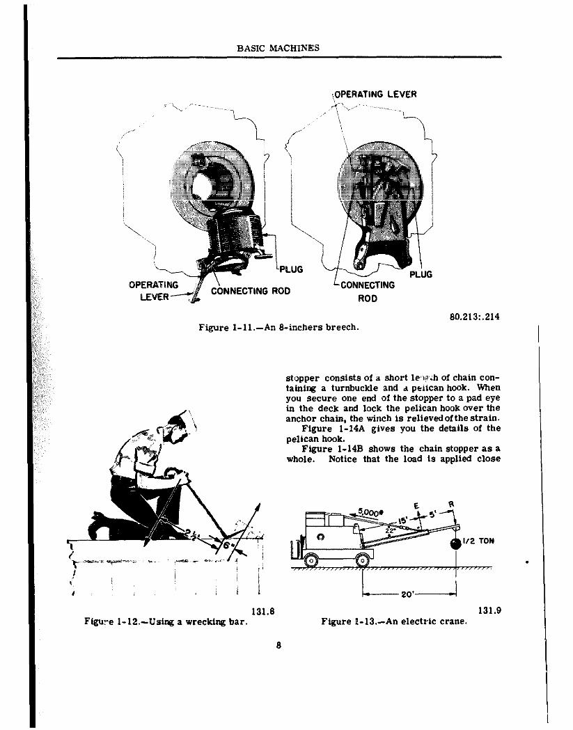
The breech of a big gun is closed with a breech plug. Figure 1-11 shows you that this plug has some interrupted screw threads on it which fit into similar interrupted threads in the breech. Turning the plug part way around locks it into the breech. The plug is locked and unlocked by the operating lever. Notice that the connecting rod is secured to the operating lever a few inches from the fulcrum. You’ll see that this is an application of a second-class lever!
You know that the plug is in there good and MECHANICAL ADVANTAGE (MA.) is an tfght
expresston of the r xtio of the applied force and But, with a mechanical advantage of
the resistance. It may be written: ten, ‘your lOO-pound pull on the handle .till twist the plug loose with a force of a half-
XI. A. =+ ton. - -
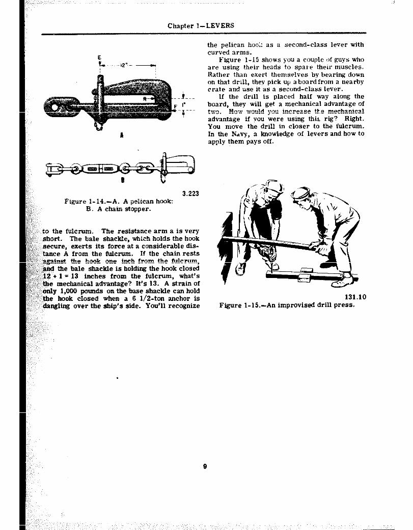
If you’ve spent any time opening crates at a base, you’ve already used a wrecking bar. The
APPLICATIONS AFLGAT blue-jacket in figure l-12 is busily engaged
AND ASHORE in tearing that crate open. The wrecking bar is a first-class lever. Notice that it has curved
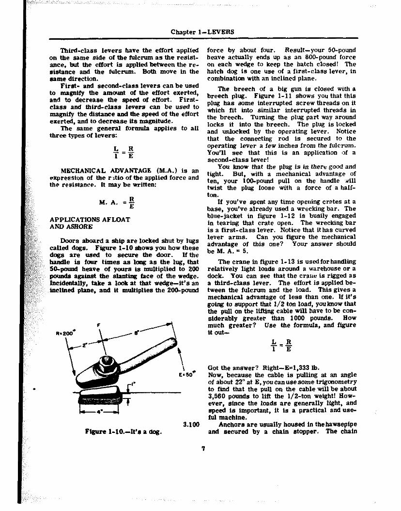
Boors aboard a sbip are locked shut by “W lever arms. Can you figure the mechanical
called dogs. Figure l-10 shows you how these advantage of this one? Your answer should
dotts are used to secure the door. lftha beM.A.=5.
haidle is four time6 as long as the lug, that SO-pound heave of yours is multiplied to 200 pound6 again6t the slanting face of the wedge. Incidsntally, take 6 look at that wedge-it’s an tncltned plane, and it multiplies the 200-pound
Flgure l-lo.-It’6 a deg. 3.100
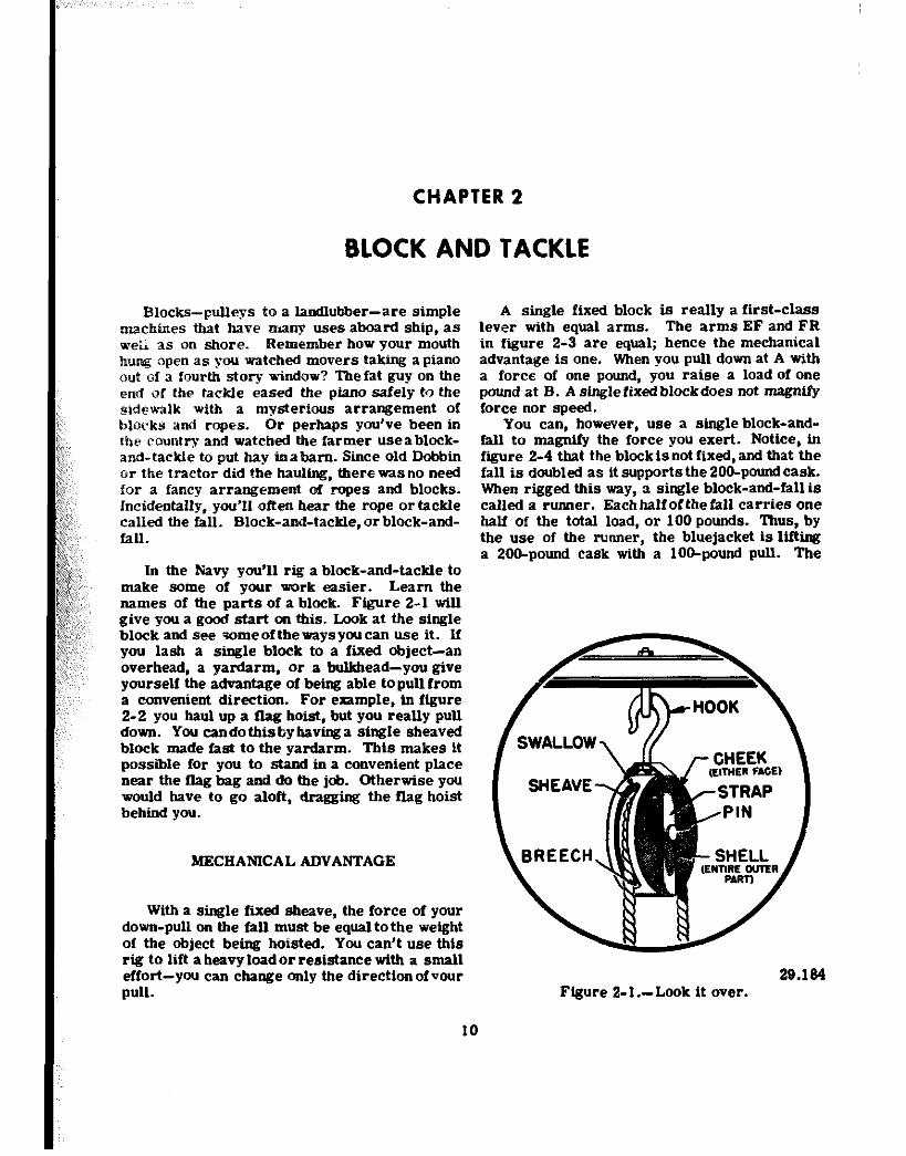
The crane in figure l- 13 is used for handling relatively light loads around a warehouse or a dock. You can see that the crane is rigged as a third-class lever. The effort is applied be- tween the fulcrum and the load. This gives a mechanical advantage of less than one. If it’s going to support that l/2 ton load, youknow that the pull on the lifting cable will have to be con- siderably greater than 1000 pounds. How much greater? Use the formula, and figure it out-
L R -=?F 1
Got the answer? Right-E=1,333 lb. Now, because the cable is pulling at an angle of about 22” at E, you can use some trigonometry to find that the pull on the cable will be about 3,560 pounds to lift the l/a-ton weight! How- ever, since the load6 are generally light, and speed is important, it is a practical and use- ful machine.
Anchor6 are usually housed in thehawsepipe and secured by a chain stopper. The chain
1
BASIC MACHINES
.‘LUG i
‘-CONNECTING
ROD
Figure I-ll.-An 8-inchers breech. 80.213:.214
stopper consists of a short lewih of chain con- taining a turnbuckle and d phiican hook. When you secure one end of the stopper to a pad eye in the deck and lock the pelican hook Over the anchor chain, the winch is relievedofthe strain.
Figure l-14A gives you the details of the pelican hook.
Figure I-14B shows the chain stopper as a whole. Notice that the load is applied close
.
131.8 131.9 Figure I-12.-Using a wrecking bar. Figure l-13.-An electric crane.
8
Chapter I-LEVERS
the pelican boo:: as a second-class lever with curved arms.
Figure l-15 shows you a couple of guys who are using their heads to sww their muscles. Rather than exert themsel&s by bearing down on that drill, they pick up aboard from a nearby
.,.i _,,. crate and use it as a second-class lever.
If the d&I is placed half way along the board. they will get a mechanical advantage of
3.223 Figure 1-14.-A. A pelican hook:
:; ,:,, /;:c, to the fulcrum. The resistance arm a is very
short. f;,f,;; The bale shaekIe, Wsh holds the hook I;i,, secure, exerts its force at a considerable dis- &,. tame A from the fulcrum. If the chain rests &against the hook one inch from the fulcrum, &against the hook one inch from the fulcrum, &;~,,,;~ind the bale shackle is holding the hook closed &;~,,,;~ind the bale shackle is holding the hook closed &, 12 + 1 = 13 inches from the fulcrum, what’s &, 12 + 1 = 13 inches from the fulcrum, what’s &,;the mechanical advantage? It’s 13. A strain of &,;the mechanical advantage? It’s 13. A strain of !Z?:J::,~ only 1,000 pounds on the base shackle can hold !Z?:J::,: only 1,000 pounds on the base shackle can hold “,‘; ‘,me hook closed when a 6 l/2-ton anchor is “,‘; ‘,me hook closed when a 6 l/2-ton anchor is
dangling over the &ii’s side. You’ll recognize dangling over the &ii’s side. You’ll recognize
9
two. .How- would-you increase tf.e mechanical advantage if you were using thir rig? Right. You move the dril! in closer to the fulcrum. In the N&q, a knowledge of levers and how to apply them pays off.
Figure l-15.-An improvised drill press.
CHAPTER 2
BLOCK AND TACKLE
Blocks-pulleys to a landmbber-are simple machines that have many uses aboard ship, as w&i as on shore. Remember how your mouth hung open as you watched movers takfng a piano out of a fourth story window? The fat guy on the end of the tackle eased the piano safely to the sidewalk with a mysterious arrangement of blocks and ropes. Or perhaps you’ve been in the country and watched the farmer useablock- and-tackle to put hay tnabarn. Since old Bobbin or the tractor did the hauling, there was no need for a fancy arrangement of ropes and blocks. Incident&y, you’ll often hear the rope ortackle called the fall. Block-and-tackIe,orblock-and- fall.
In the Navy you’ll rig a block-and-tackle to make some of your work easier. Learn the names of the parts of a block. Figure 2-l will give you a good start on this. Look at the single block and see some of the ways you can use it. If you lash a single block to a fixed object-an overhead, a yardarm, or a buRrhead-you give yourself the advantage of being able topullfrom a convenient direction. For exampIe, tn ffgure 2-2 you haul up a flag hoist. but you really pull down. You candothfsbybavfmfa sfngle sheaved block made fast to the yardarm. This makes it possible for you to stand in a convenient place near the flag bag and do the job. Otherwise you would have to go aloft, dragging the flag hoist behind you.
MECHANICAL ADVANTAGE
With a single fixed sheave, the force of your down-pull on the fall must be equal tothe weight of the object being hoisted. You can’t use this rig to lift aheavyloadorresistance with a small effort-you can change only the directionof vour pull.
A single fixed block is really a first-class lever with equal arms. The arms EF and FR in figure 2-3 are equal; hence the mechanical advantage is one. When you pull down at A with a force of one pound, you raise a load of one pound at 8. A single fixed blockdoes not magnify force nor speed.
You can, however, use a single block-and- fall to magntfy the force you exert. Notice, in figure 2-4 that the block is not fixed, and that the faU is doubled as it supports the 200-poundcask. When rigged this way, a single block-and-fall is called a runner. Each half of the fall carries one half of the total load, or 100 pounds. Thus, by the use of the runner, the bluejacket is lffta a 200-pound cask with a loo-pound pull. The
29.124 Figure 2-l.-Look it over.
10
Chapter 2-BLOCK AND TACKLE
Figure 2-2.-A flag hoist.
29.181
69.122
Figure 2-3.-No advantage.
that the load is raised. However, if you can lift
mechanical advantage is two. Check this by the formula:
M A ;;!i=?.@or2 . . E loo’
The single movable block in this setup is really a second-class lever. See figure 2-5. Your effort E acts upward upon the arm EF, which is the diameter of the sheave. The re- sistance R acts downward on the arm FR, which is the radius of the sheave. Since the diameter is twice the radius, the mechanical advantage is two.
But, when the effort at E moves up two feet, the load at R is raised onlyonefoot. That’s one thing to remember about blocks and falls-if you are actually getting a mechanical advantage from the system, the length of rope that passes through your bands is greater than the distance
11
a big load with a Small effort, you don't care how much rope you have to pull.
The bluejacket in figure 2-4 isinanawkward position to pull. If he had another single block handy, he could use it to change the direction of the pull, as in figure 2-6. Thissecond arrange- ment is known as a gun tackle purchase. Because the second block is fixed, it merely changes the direction of pull-and the mechanical advantage of the whole system remains two.
You can arrange blocks in a number of ways, depending on the job to be done and the me&an- ical advantage you want to get. For example, a luff tackle consists of adoubleblockanda single block, rigged as in figure 2-7. Notice that the weight is suspended by the three parts of rope which extend from the movable single block. Each part of the rope carries its share of the load. If the crate weighs 600 pounds, then each of the three parts of the rope supports its share- 200 pounds. If there’s a pull of 200 pounds down- ward on rope B, you will have to pull downward
BASIC MACHINES
a winch. The winch could take it, but the rope couldn’t.
Now for a review of the points you have learned abzzmt blocks, and then to some practical appllcattons atx,ard ship-
W&h a single fixed block the only advantage is the change of direction of the pull. The mecban- ical advantage is still one.
A single movable block gives a mechanical advantage of two.
Many combinations of single, double, and triple blocks csnbe riggedtogivegreateradvan- tages.
l3g~re 2-L-A runner. 29.187
with a force o’?W son A to counterbalance the pull onB. Neglecting the friction in the block, a pull of 200 pow&s is all tbat is necessary to raise the crate. The meclw~%; advantage is:
R 500 M.A. =~=~=3
Here’s a good tip. Ifyoucount the number of the parts of rope going to and from the movable block, you can figure the mechanical advantage at a glance. This simple rule will help you to quickly approximate the mechanical advantage of most tackles you see in the Navy.
Many combiitiocls of single, double, and triple sheave blocks are possible. Two of these combinations are shorw in figure 2-8.
If youcansecurethedeadendofthe fall to the movable block,theadvautageisincreassdbyone. Notice that this is done in fiire 2-7. That is a good point to remember. Don’t forget, either, that the strength of yourfall-rope-isallmiting factor in any tackle. Be sure your fall will carry the load. There is no point in rtgglng a six-fold purchase which carries a &ton load with two triple blocks on a 3-inch manila ropeattachsdto Figure 2-Z.-It’s 2 to 1.
12
Chapter 2-BLOCK AM) TACKLE
swing it onto the deck, or to shift any load a short distance. Ftgure 2-9 shows you how the load is
$ first picked up by the yard tackle. The stay tackle La left slack. After the load is raised to
;,, 29.187
Figure 24-A gun tackle. :_ ,, ;;;p ,,:, ii:
:’ A general rule of thumb isthattheamuber of :,’ the pPMofthefaIlgoic@oamifrom the movable
block tells you the approximate mechanical ad- ,,’ vaohge of tlxd tackle.
ffyottflxthedeadedofthefslltothemov- able block you increase the mecbatUca1 advantage
,Ay ate.
APPLICATIONS AFLOAT AND ASBORE
Blocks and tackle are osed for a great num- berdlUtingatxlmovingjabsafluatandashore. ‘lbe five or six basic ComblmUam are used over aml over agaln in many sUuatlate. Cargo is loaded aboard, depth charges are placed Intbeir racb. life boats are lowered over the side bv the use of tbls machine. Eeavy machhery, guns, amlgtmuamtsare~&topositionwlththe nM otldoeks aml tackle. blrtJmu6uulsitua- UOIU, bluejaekste flmi this maehine useful and efflcleot.
Yard ud stay tackles are used on shipboard whcl, yew mat toplckuprloadfrom the hold and
13
the height necessary to clear obstructions, you take up on the stay *!%kle, and ease off on the yard fall. A glance at the rig tells you that the mechanical advantage of each of these tackles is only two. Youmaythinkthat it isn’t worth the trouble to rig a yard and stay tackle with that small advantage just to move a 400-pound crate along the deck. However, a few minutes spent in rigging may save many unpleasant hours with a sprained back.
If you want a high mechanical advantage, a luff upon luff is a good rig for you. You can raise heavy loads with this setup. Ftgure 2-10 show’s you how it is rigged. If you apply the rule by which you count the parts of thefallgolng. to and from the movable blocks, you find that block A gives a mechanical advantage of 3 to 1. Block B has four parts of fall running to and from it, a
Figure 2-7.-A luff tackle. 29.187
BASIC MACHINES
29.187 . ._ Figure 2-8.-Some outer mattes.
mechanical advantage of 4 to 1. The mechanical advantage of those obtained from A is multiplied four times In B. The overali mechanical advan-
” ,tage of a luff npon luff is the product of the two mechanical advantages-or 12.
Don’t make the mistake of adding mechanical advantages. Always muItiply them.
You can easily figure out the M.A. for the ap- paratus shown in figure 2-10. Suppose the load weighs 1,200 pounds. Since it is supported by the parts 1, 2, and 3 of the fall running to and from block A, each part must be supporting one third of the load, or 400 pounds. If part 3 has a pull of 400 pounds on it, part 4 which is made fast to block B, also has a 400-pound pull on it, There are four parts of the second fall going to and ,from block B, and each of these takes an
WAY YARD STAY YARD STAY
29.187 Figure 2-9.-A yard and stay tackle.
equal part of the 400-pound pull. Therefore, the hauling part requires a pull of only l/4 x 400, or 100 pounds. So, here you have a li$-isa; pull raising a 1,200-pound load. mechanical advantage of 12.
In shops ashore and aboard ship you are almost certain to run into a chain hoist, or differential pulley. Ordinarily, these hoistsare suspended from overhead trolleys, and areussd to lift heavy objects and move them from one part of the shop to another.
29.187 Flgure 2-lo.-Luff upon luff.
Chapter 2-BLDCK AND TACKLE
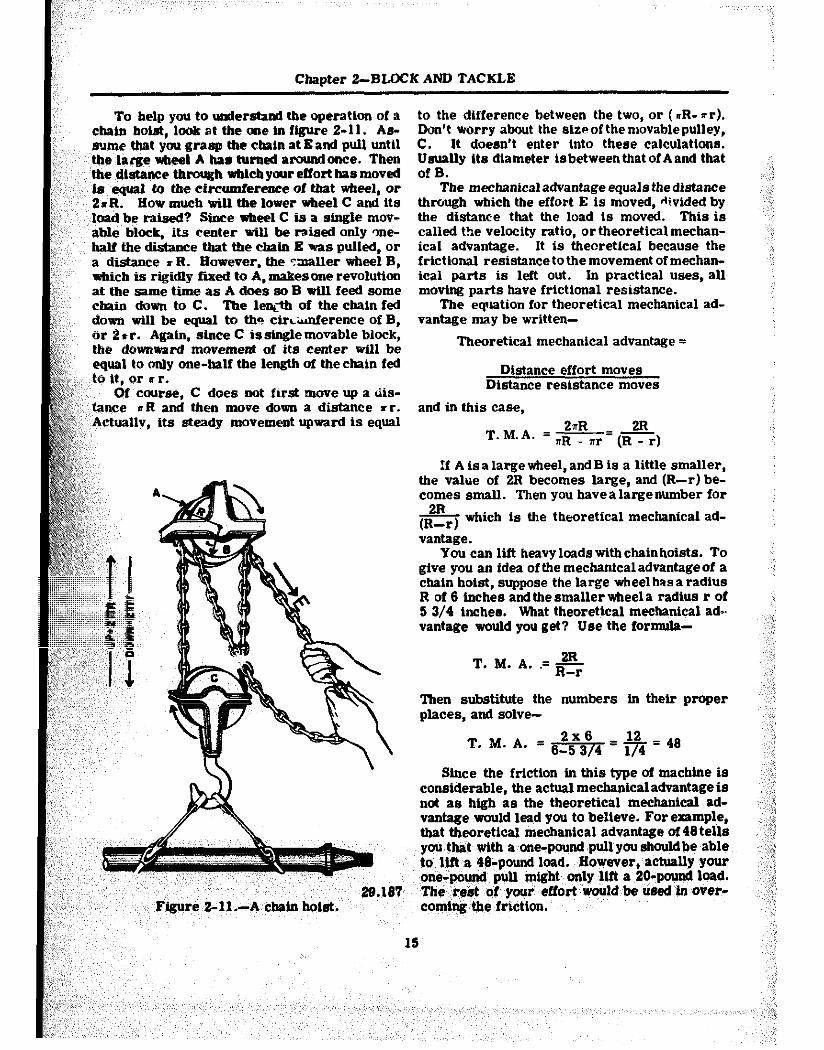
To help you to umterstand the operatton of a chain holst, look at the one tn figure 2-11. As- sume that you grasp the chain at Band pull until the large wheel A has turned aroundonce. Then ‘the dbtsnce through wldcb your effort has moved
” is equsl to the circumference of mat wheel, or 2vR. How much will the lower v&eel C and its
‘load be ratsed? Snce v&eel C is a single mov- able block, its center wtll be raised only one- half the distance that the chain E was pulled, or a dtstance s R. However. the smaller wheel B, which is rigidly fixed to A, makesone revolution atthesametimeasAdaessoBarillfeedsome chain doam to C. The le@h of the chain fed doppa wUl be equal to the ctrL-tierence of B, or 2tr. Again, since C issiogle movable block, the downward movement of its center wfll be equal to only one-half the length of the chain fed
,:~ to It, or rr. Qf course, C does not first move up a Liis-
Y,T tame rR and then move down a distance rr. ji:;~,’ Actually, its steady movement upward is equal II $& :::,,
to the difference between the two, or (xR- *r). Don’t worry about the slzaof the movable pulley, C. It doesn’t enter Into these calculations. Usually its diameter Isbetween that of A and that ofB. - ofB. -
The mechanicaladvantageequals thedistance The mechanicaladvantageequals thedistance through which the effort E is moved, divided by through which the effort E is moved, divided by the distance that the load is moved. This is the distance that the load is moved. This is called the velocitv ratio. or theoretical mechan- called the velocitv ratio. or theoretical mechan-
28.187 “’ Ffgure~2-1~.-A~chafn hoist.
ical advantage. -It is theoretical because the frictional resistance to the movement of mechan- ical parts is left out. In practical uses, all moving parts have frictional resistance.
The equation for theoretical mechanical ad- vantage may be written-
Theoretical mechanical advantage =
Distance effort moves Distance resistance moves
and in this case,
2nR 2R T.M.A. =,Rm=(crj
If A is a large wheel, and B is a little smaller, the value of 2R becomes large, and (R-r) be- comes small. Then you havealargenumber for
& which is the theoretical mechanical ad-
vantage. You can lift heavyloadswithchainhoists. To
nive YOU an idea of the mechanical advantage of a &atn hoist, &pose the large wheel hasa radius R of 6 inches andthesmallerwheela radius r of 5 3/4 inches. What theoretical mechanical ad*, vantage would you get? Use the formula-
2R T. M. A. .= ~-r
lben substitute the numbers in their proper places, and solve-
T. M. A. = &$ = +$ = 48
Since the friction in this type of machine is considerable, the actual mechanical advantage is not as high as the theoretical mechanical ad- vantage would lead you to believe. For example, that theoretical mechanical advantage of48tells you that with a one-poundpullyoushouldbe able to lift a ,48-pound load., However, actually your one-pound pull might only flft a 2O~pound load. ‘l’h.5 res$ of ‘your ~effortwould be used In over- coming the friction.
CHAPTER 3
THE WHEEL AND AXLE
Rave you ever tried to open a door when the kmb was missing? lf you have, you know that trying to twist that small four-sided shaft with vour fingers is tough work. Thatgives you some appreciation of the advantage you get by using a knob. The doorknobisaneaample of a simple machine called a wheel and axle.
The steering wheel on an automobile, the handle of an ice cream freezer, a brace and bit-these are familiar eaamples of this type of simple machine. As you know from your experience with these devices, the wheel and axle is commonly used to multiply the force you exert. If a screwdriver won’t do a job because you can’t turn it, you stick a screw- driver bit in the chuck of a brace and the screw probably goes in with little difficulty.
There’s one thing you’lI want to get straight right at the begbming. The wheel-and-axle machine consists of a wixel or crank rigidly attached to the axle, which turns with the wheel. ‘Bum, the front wheel of an automobile IS not a wheel-and-axle machine because the axle does not turn with the *eel.
MRCRAIUICAL ADVANTAGE
Bow does the wheel-and-axle arrangement help to magnify the force you exert? Suppose you use a screwdriver bit in a brace to drive a stubborn screw. Lookat figure 3-1A. Your effort is applied on the bandle which moves in a circular path, the radius of which is 5 inches. If you apply a IO-pomai force on the handle, how big a force will be exerted against the re- sistance at the screw? Assume the radius of the scremiriver blade is l/4 inch. You are really uslsg the brace as a second-class lever- see figure 3-18. The siae of the resistance
16
which can be overcome can be found from the formula-
R +=E
In which-
L = radius of the circle through which the ttindle turns,
1= one-half the width of the edge of the screwdriver blade,
R = force of the resistance offered bv the screw,
E = force of effort applied on the handle.
Substituting in the formula; and solving:
= 266 lb.
This means that the screwdriver blade will tend to turn the screw with a force of 266 pounds. The relationship between the radii or the diameters, or the circumferences of the wheel and axle tells you how great a mechanical advantage you can get.
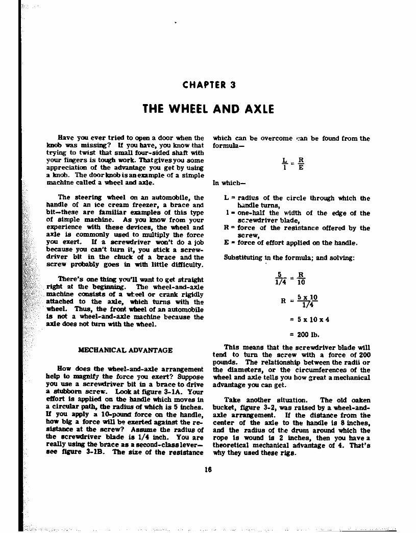
Take another situation. The old oaken bucket, figure 3-2, was raised by a wheel-and- axle arrangement. If the distance from the center of the axle to the handle is 8 inches, and the radius of the drum around which the rope is wound is 2 inches, then you have a theoretical mechanical advantage of 4. That’s why they used theee rigs.
Chapter 3-THE WHEEL AND AXLE
A B 44.20
Figure 3-1.-R magnifies your effort.
MOMENT OF FORCE
In a number of situations you can use the wheel-and-axle to speed up motion. The rear- wheel sprocket of a bike, along wtth the rear wheel it.seIf~ is an example. When you are pedaling, the sprocket is ftaed to the wheel, so the combination is a true aheel-and-axle ma- chine. Assume that the sprocket has a cir- cumference of 8 Whes, and the wheel clr- cumference Ls 80 Inches. If you turn the ‘sprocket at a rate of one revolutton per second, each sprocket tooth moves at a speed of 8 inches per second. 8tnce the wheel makes one revolution for each revolution made by the sprocket, any point on the tire must move through a distance of 80 inches in one second. So, for every eight-tnch movement of a point on the sprocket, you bave moved a correspond- Ing point on the wheel through 80 inches.
Since a complete revoluticvi of the sprocket and wheel requtres atly one second, the speed of a point on the circumference of the wheel is 80 Inches per second, or ten tfmes the speed of a tooth on the sprocket.
@fOTRz Roth sprocket ad wheel make the WI&e number of revoluttons per second so the spwdoftumiegforthetwoisthesame.)
131.11 Figure 3-Z.-The old oaken bucket.
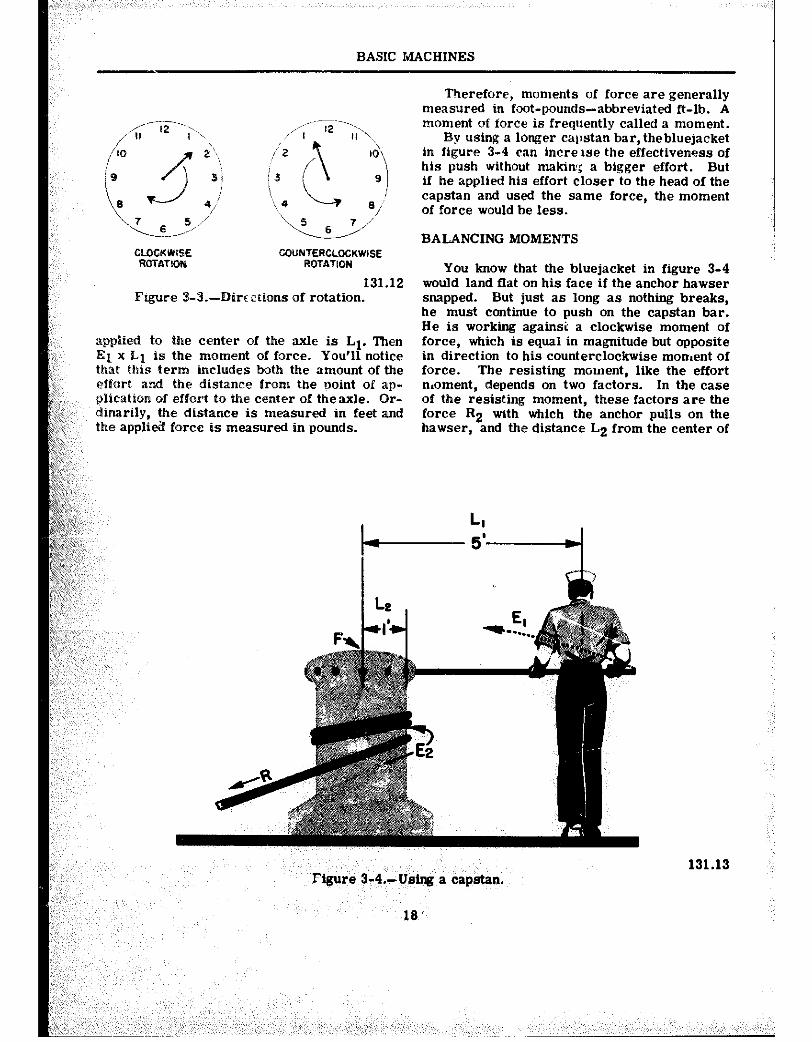
Here is an idea which you will find useful in understanding the wheel and axle, as well as other machines. You probably have noticed that the force you apply to a lever tends to turn or rotate it about the fulcrum? You also know that a heave on a fall tends to rotate the sheave of the block and that turning the steering wheel of a car tends to rotate the steering column. Whenever you use a lever, or a wheel and axle, your effort on the lever arm or.the rim of the wheel tends to cause a rotation about the ful- crum or the axle in one direction or another. U the rotation occurs in the same direction as the hands of a clock, that direction 18 called clockwtse. If the rotation occur* in the op- posite direction from that of the hands of a clock, the direction of rotationiscalledcouuter- clockwise. A glance at figure 3-3 will make clear the meaning of these terms.
You have already seen that the result of a force acting on the handle of the carpenter’s brace depends not only on the amount of that force but also on the distance from the handle to the center of rotation. From here on you’ll know this result as a moment of force, or a torque (pronounced tork). Moment of force and torque have the same meaning.
Look at the effect of counterclockwise move- ment ot the capstan bar m figure 3-4. Here the amount of the effort is designated El and the distance from the point where this force is
17
BASIC MACHINES
CLocKWsE GOUNTERCLOCKWlSE RoTA?K)N ROTATION
131.12 Figure 3-3.-Wrcccions of rotation.
applied to the center of the axle is Ll. Then El x L1 is the moment of force. You’ll notice that this term includes both the amount of the cfforl and the distance from the point of ap- pliealion of effort to the center of theaxle. Or- dinarily, the distance is measured in feet and the appli& force is measured in pounds.
Therefore, moments of force are generally measured in foot-pounds-abbreviated ft-lb. A moment of force is frequently called a moment.
By using a longer capstan bar, thebluejacket in figure 3-4 can tncre tse the effectiveness of his push without makim{ a bigger effort. But if he applied his effort closer to the head of the capstan and used the same force, the moment of force would be less.
BALANCING MOMENTS
You know that the bluejacket in figure 3-4 would land fkat on his face if the anchor hawser snapped. But just as long as nothing breaks, he must continue to push on the capstan bar. He is working against a clockwise moment of force, which is equal in magnitude but opposite in direction to his counterclockwise moment of force. The resisting moment, like the effort n.oment, depends on two factors. In the case of the resisting moment, these factors are the force R2 with which the anchor pulls on the hawser, and the distance L2 from the center of
Figure 3-4.-U&g a capstan.
18 ”
131.13
Cbapter 3-THE WHEEL AND AXLE
the capstan to its rim. The existence of this resisting force would be evident if the blue- jacket let go of the capstan bar. The weight of the anchor pulpit on the capstan would cause the whole works to spin rapidly in a clockwise direction-and good-bye anchor! The principle involved here is that urlPenrvertheeounterclock- wise md the clockwise ~~~e~ts of force are in balance, tbe machine either movesat a steady speed or remains at rest. I
This idea of the balance of moments of force can be summed up by the eapression-
CLOCKWSE MOMENTS = COUNTERCLOCKWISE MOMENTS
And, since a moment of force is tbe product of the amount of the force times the distance the force acts from the center of rotation, this rxprerrion cf equality may be written-
131.14 Figure 3-5.-A practical application.
ElxLl = E2xL2
In which- El = fscrrce of effort, Ll = distance from fulcrum or axle to point
where force is applied, E = force of resistance, Li = distance from fulcrum or center of axle
to the point where resistance isapplied.
‘fXAMPLE 1 Put this formula to work on a capstan prob-
lem. A single capstan bar is gripped 5 feet from the center of a capstan head with a radius of one foot. A l/Z-ton anchor is to be lifted. How big a push does the sailor have to exert?
First, write down the formula-
ElxLl =E2xL2
Here Ll= 5; E2 = 1,000 pounds; and L2 = !. Substitute these values in the formula, and It
becomes:
and-
E1X5 =1,000x1
F =~=2OOpounds ‘1
EXAMPLZ 2 Consider now the sad case of Slim and Sam,
as illustrated in figure 3-5. Slim has suggested that they carry the 300-pound crate slung on a
19
bandy IO-foot i~ole. He was smart enough to slide the load up 3 feet from Sam’s shoulder.
Here’s how they made out. Use Slim’s shoulder as a fulcrum F1. Look at the clock- wise moment caused by the300-poundload. That load is five feet away from Slim’s shoulder. If RI is tbeload, and L1 the distance from Slim’s shoulder to the load, the clockwise moment MA is-
*A = Rl x Ll = 300 x 5 = 1,500 ft..lb.
With Slim’s shoulder still acting as the ful- crum, the resistance of Sam’s effort causes a counterclockwise moment MB acting againstthe load moment. This counterclockwise moment is equal to Sam’s effort E L3 from his shoulder to \
times the distance
Slim’s shoulder. he fulcrum F1 at
Since L2 = 8 ft., the formula is-
ME = E2xL3 = E2x8 = 8E2
But there is no rotation, so the clockwise mbment and the counterclockwise moment are equal. MA = MB. Hence-
1.500 = 8~~
E = 1,500 = 18’7.5 pounds. 2 8
So poor Sam is carrying 187.5 pounds of the 300-pound load.

Chapter 3-THE WHEEL AND AXLE
the capstan to its rim. The existence of this resisting force would be evident if the blue- jacket let go of the capstan bar. The weight of the anchor pulpit on the capstan would cause the whole works to spin rapidly in a clockwise direction--and good-bye anchor! The principle involved here is that urlPenevertheeounterclock- wise md the clockwise moments of force are in balance, the machine either movesat a steady speed or remains at rest. I
This idea of the balance of moments of force cm be summed up by the expression-
CLOCKWSE MOMENTS = COUNTERCLGCKWfSE MOMENTS
And, since a moment of force is the product of the amount of the force times the distance the force acts from the center of rotation, this rxprerrlon cf equality may be written-
131.14 Figure 3-5.-A practical application.
ElxLl = E2xL2
In which- El = fscrrce of effort, Ll = distance from fulcrum or axle to point
where force is applied, E = force of resistance, Li = distance from fulcrum or center of axle
to the point wbereresistance isapplied.
‘fXAMPLE 1 Put this formula to work on a capstan prob-
lem. A single capstan bar is gripped 5 feet from the center of a capstan head with a radius of one foot. A l/2-ton anchor is to be lifted. How big a push does the sailor have to exert?
First, write down the formula-
ElxLl =E2xL2
Here Ll= 5; E2 = 1,000 pounds; and L2 = !. Substitute these values in the formula, and It
becomes:
and-
E1X5 =1,000x1
F =~=ZOOpcnmds '1
EXAMPLZ 2 Consider now the sad case of Slim and Sam,
as illustrated in figure 3-5. Slim has suggested that they carry the 300-pound crate slung on a
19
handy IO-foot .>ole. He was smart enough to slide the load up 3 feet from Sam’s shoulder.
Here’s how they made out. Use Slim’s shoulder as a fulcrum Fl. Look at the clock- wise moment caused by the300-poundload. That load is five feet away from Slim’s shoulder. If Rl is theload, and L1 the distance from Slim’s shoulder to the load, the clockwtse moment MA is-
*A = R1 x Ll = 300 x 5 = 1,500 ft..lb.
With Slim’s shoulder still acting as the ful- crum, the resistance of Sam’s effort causes a counterclockwise moment MB acting againstthe load moment. This counterclockwise moment is equal to Sam’s effort E L3 from his shoulder to \
times the distance
Slim’s shoulder. he fulcrum F1 at
Since L2 = 8 ft., the formula is-
MB = E2xL3 = E2x8 = 8E2
But there is no rotation, so the clockwise mbment and the counterclockwise moment are equal. MA = MB. Hence-
1,500 = 8E2
E = 1,500 = 18’7.5 pounds. 2 0
So poor Sam is carrying 187.5 pounds of the 300-pound load.
Chapter S-THE WHEEL AND AXLE
When an object is at rest or is moving steadily, the clockwise moments are just equal and opposite to the counterclackwise moments.
Moments of the force, depend upon two factors--the amount oftheforce,andthedistance from the fulcrum or axis to the point where the force is applied.
When two equal forses are applied at equal distances on opposite sides of a fulcrum, and move in opposite directions so that they both tend to cause rotation about the fulcrum, 3ou have a couple.
APPLICATIONS AFLOAT AhV ASHORE
A trip to th? ewine room makes you realize how important the wheei and axle is on the modern ship. Everywhere you look you see wheels of all sizes and shapes. Most of them are used to open and close valves quickly. One common type of valve is shown in figure 3-7. Turning the wheel causes the threaded intern to rise and open the valve. Since the valve must close water-tight, air-tight, or steam- tight, all the parts mmt fit snugly. To move the stem on most valves without the aid of the
,, wheel would be impossible. The wheel gives ,, you the necessary me&an&I advantage.
You’ve handled enough wrenches to know ,“that the longer the handle, tba tighter you can
;,,‘:,turn a nut. Ackaally, a wrench is a wheel- <;: and-axle machine. You can consider the handle _I,,: as one spoke of a wheel,andtheplace where you :,I,,,,
take hold of the handle as a point on the rim. The nut wbioh is held in the jaws of the wrench can be compared to the axle.
You know that you can turn a nut too tight- and strip the threads or cause internal parts to seize. This is especially true when you are taking up on bearings. In order to make the proper adjustment, you use a torque wrench. There are several types. Figure 3-8 shows you one that is very simple. When you pull on the handle, its shaft bends. The rod on which the pointer is fixed does not bend-so the pointer indicates on the scale the torque, or moment of force, that you are exerting. The scale is generally stated in pounds, although it is really measuring foot-pounds of torque. If the nut is to be tightened by a moment of Soft-lb, you pull * until the pointer is opposite the number 90 on the scale. The servicing or repair manual on an engine or piece of machinery generally tells you what the torque-or moment of force-should be on each set of nuts or bolts.
The gun pointer uses a couple to elevate and depress the gun barrel. He cranks away at a hand-wheel that has twohandles. Theright-hand handle is on the opposite side of the axle from the left-hand handle-190” apart. Look atfigure 3-9. When he pulls on one handIeand pushes on the other, he’s producing a couple. But if he lets go the left handle to scratch himself, and cranks only with his right hand, he no longer has a couple-just a simple first-class lever! And he’d have to push twice as hard with one hand.
Figure 3-7.-Valves. Figure 3-&-A simple torque wrench.
21
BASIC MACHINES
A system of gears--a gear train-transmits handle also rotates the wheel in the same direc- the motion to the barrel. A look at figure 3-10 tion with an equal moment. Thus the total twist will help you to figure the forces involved. The or torque on the wheel is 10 + 10 = 20 ft-lb. radius of the wheel is 6 inches-l/2 foot-and To get the same moment with one hand, applying each handle is being turned with a force of, a 20-pound force, the radius of the wheel would say, 20 puunds. The moment on the top which have to be twice as great- 12 inches, or one foot. tends to rotat? tlicb wheelinaclockwisedirection The couple is a convenient arrangement of the is equ:J to 20 times l/2 = 10 ft-lb. The bottom wheel-and-axle machine.
131.17 Figure 3-9.-A pointer’s handwheel.
131.19 Figure 3-10.-Developing a torque.
CHAPTER 4
THE INCLINED PLANE AND THE WEDGE
TIIEBARRELROLL Now apply the formula to thisproblem-
You have probably watched a driver load In this case, L = 9 ft.; 1 = 3 ft; and R = 300 lb. barrels on a truck. The truck is backed up to the curb. The driver places a long double
9lank or ramp from the sidewalk to the tail gate, and then rolls the barrel up the ramp.
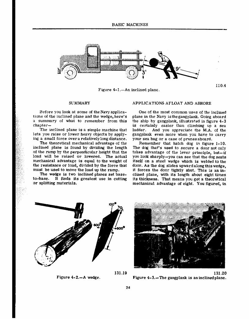
,,, A 32+allon barrel may weigh close to 3OOpounds “when full, and it would be quite a job to lift one ::np into the truck. Actually, the driver is using :;,a Ainple machine called the inclined plane. :i:You ,have seen the inclined plane used in many ~~&$ations. Cattle ramps, a mountain highway, ~~@+I$; ‘hi-2 ‘pngplank are familiar examples.
$@$;;;,:: ,The ,mclined plane permits you to overcome &Ia~,e ,resistance by applying a relatively small efgrce through a longer distance than the load is &&&& : LoOk eat figure 4-I. Here you see the ‘&$,& basing me 30(I-po,md barrel np toBebed $$the truck, three feet above the sidewalk. He f;;;;~#~:-using a plank nine feet long. If he didn’t use ;;:the,;ramp at all, he’d have to apply a 309-pound ;‘~:~force’straight uptbroughthethree-foot distance. ‘,:~With the~‘ramp, however, he can apply his effort ~;:over,~tl~eentireninefeetof tbeplankas the barrel ,:,~~isslowly :@led up to a height of three feet. It ~,~Io@s, then, as ifhecoiddnseaforce only three- :,, ~ninths of 309, or 100 pounds, to do the job. And ‘,‘,bit is,actually the sitt@ion.
:‘,Iere’s the formula. Remember it from +?!” I?
L: ‘R -=- : ,: ,,,, ,l; ,E ,,,
,:~:,~:,,Fp’ wbich+L r”l,et#b :of t$ie :ramp, measured al*:Uie slope,,,, ,:’ : :,::i,:,, ,” (I keight of the amp,
R, = weight ‘of object to be raised, ,,,, ,: ‘,’ ~orlowersd,
‘E = force required, to raise or ,’ iower object
By substituting these values in the formula, you get-
;+
9E = 900
E = 100 pounds
Since the ramp is three times as long as its height, the mechanical advantage is three. You find the theoretical mechanical advantage by dividing the total distance through which your effort is exerted by theverticaldistancethrongh which the load is raised or lowered.
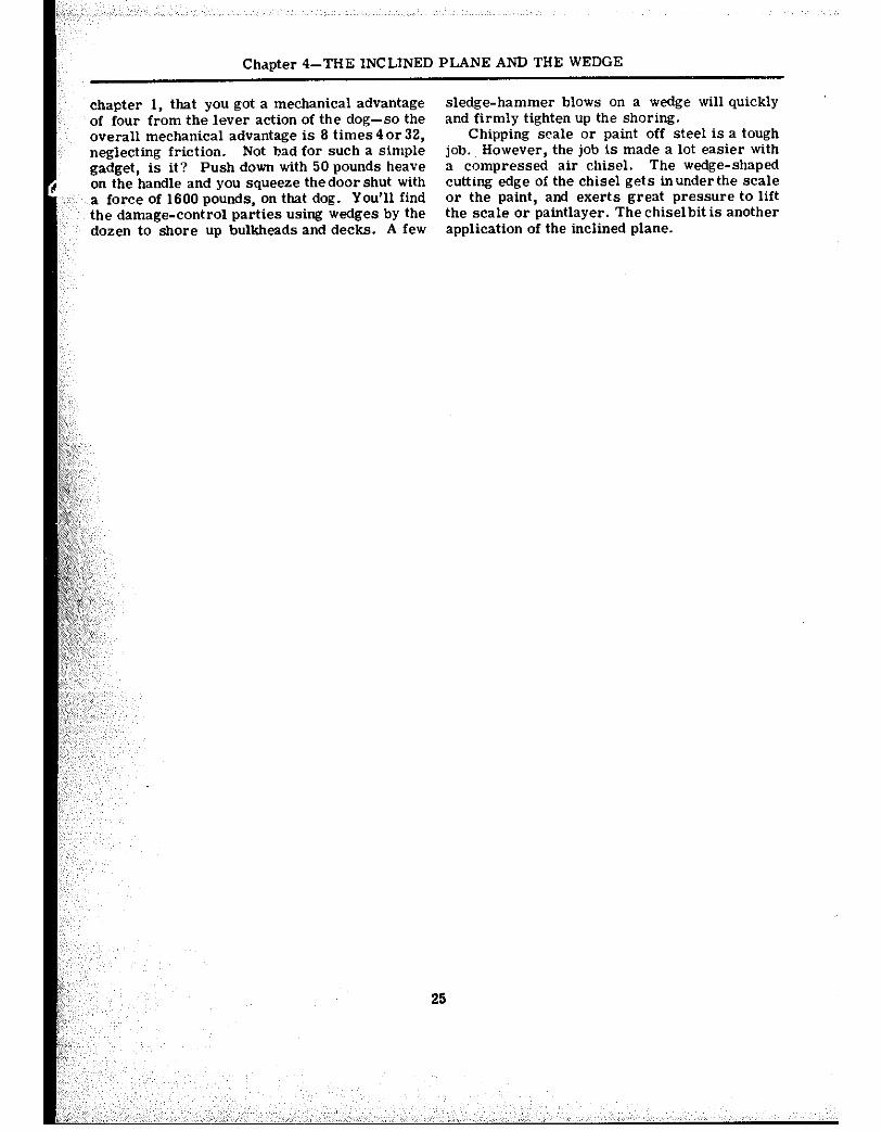
THE WEDGE
The wedge is a special application of the inclined plane. You have probably used wedges. Abe Lincoln used a wedge to help him split logs into rails for fences. Thehladesof knives, axes, hatchets, and chisels act as wedges when they are forced into a piece of wood. The wedge is two inclined planes, set baseto-base. By driv- ing the wedge full-length into the material to he cut or split,’ the material is forced apart a dis-, tance equal to the width of the broad end of the wedge. See figure 4-2.
Long, slim wedges give high mechanical ad- “, vantage. For example, the wedge of .figure 4-2 has : a mechanical, advantage of six. ” ‘, Their greatest value, however, lies in the fact that you,‘can, use ~,them in situations where other ,” simple machines won’t ,‘: work. Imagine the ‘_: trouble you’d have trying to, pull a leg apart with a system of pulleys.
BASIC MACHINES
Figure 4-1 .-An inclined plane
SUMMARY APPlJCATIONS AFLOAT AND ASHORE
Before you look at some of the Piavy applica- tions of the inclined plane and the wedge, here’s a summary of what to remember from this chapter-
The inclined plane is a simple machine that lets you raise ox- lower heavy objects by apply- ing a small force over a relatively long distance.
The theoretical mechanical advantage of the inclined plane is found by dividing the length of the ramp by the perpendicular height that the load will be raised or lowered. The actual mec.banical advantage is equal to the weight of the resistance or load, divided by the force that must be used to move the load up the ramp.
The wedge is two inclined planes set base- to-base. It finds its greatest use in cutting or splitting materials.
Figure 4-2.-A wedge.
24
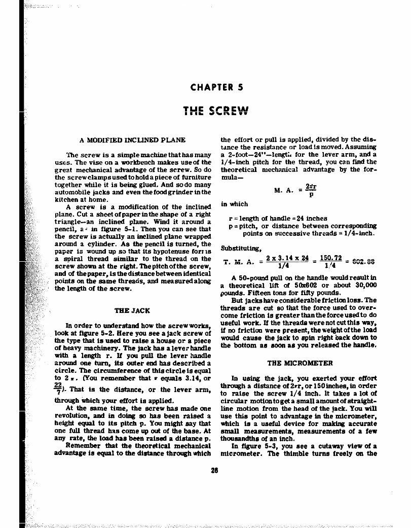
One of the most common uses of the inclined plane in the Navy is the gangplank. Going aboard the ship by gangplank, illustrated in figure 4-3 is certainly easier than climbing up a sea ladder. And you appreciate the M.A. of the gangplank even more when you have to carry your sea bag or a case of prunes aboard.
Remember that hatch dog in figure l-10. The dog that’s used to secure a door not on!y tzkes advz:tage of the lever principie, but-if you look sharply-you can see that the dog seats itself on a steel wedge which is welded to the daor. As the dog slides upward along this wedge, it forces the door tightly shut. This is an in- clined plane, with its length about eight times its thickness. That means you get a theoretical mechanical advantage of eight. You figured, in
Figure 4-3.-The gangplank is an inclinedplane.
Chapter 4-THE INCLINED PLANE AND THE WEDGE
chapter 1, that you got a mechanical advantage sledge-hammer blows on a wedge will quickly of four from the lever action of the dog-so the and firmly tighten up the shoring. overall mechanical advantage is 6 times 4 or 32, Chipping scale or paint off steel is a tough neg!ecting friction. Not bad for such a simple job. However, the job is made a lot easier with gadget, is it? Push down with 50 pounds heave a compressed air chisel. The wedge-shaped on the handle and you squeeze the door shut with cutting edge of the chisel gets in under the scale a force of 1600 pounds, on that dog. You’ll find or the paint, and exerts great pressure to lift the damage-control parties using wedges by the the scale or paintlayer. The chiselbit is another dozen to shore up bulkheads and decks. A few application of the inciined plane.
25
CHAPTER 5
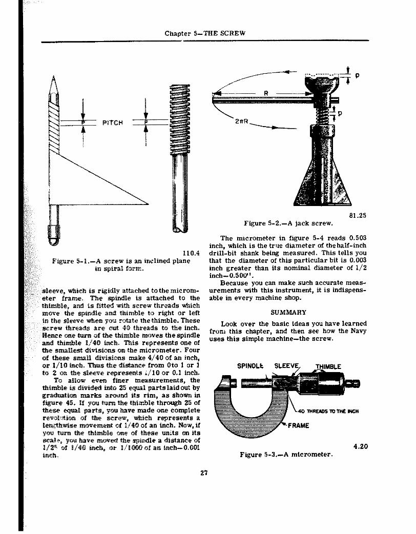
THE SCREW
A MODIFIED INCLJNBD PLANE
The screw is a simple machine that has many uses. The vise on a workbench makes useof the great mechanical advantage of the screw. So do the screwelampsusedtoholdapieceof furniture together while it is being glued. And sodo many rutomoblle jacks and even thefoodgrinderinthe kItshen at home.
A screw is a modification of the inclined plane. Cut a sheetofpapertntheshape of a right triangle-an inclined plane. Wind it around a pencil, a; in figure S-l. Then you can see that the screw is actually an inclined plane wrapped around a cylinder. As the pencil is turned, the paper is wound *up so ‘%at its hypotenuse forr~xi a spiral thread similar to the thread on the screw shown at the right. Thepitchofthe screw, and of the paper, is thedistancebetween identical points on the same threads, and measuredalong the length of the screw.
TRK JACK
In order to understand how the screw works, look at ftgure 5-2. Here you see a jack screw of the type that is ueed to nlse a house or a piece of heavy machinery. The jack has a lever handle with a length r. If you pull the lever handle around one turn, its outer end has described a circle. The circumference of this circle is equal to 2.. 22
lyou remember that I equals 3.14, or
7). That is the distance, or the lever arm,
through arhich your effort is applied. At the same time, the screw has made one
revolution, and in doing so has been raised a height equal to its pitch p. You might say that one hll thread has come up out of the base. At any rate, the lued hse beea ralssd a distance p.
Remember that the theoretIca mechanical advantage is equal to the dtstsnce through whtch
the effort or pull is applied, divided by the dis- tdnce the resistance or load is moved. Assuming a 2-foot-24”-lengt;. for the lever arm, and a l/4-inch pitch for the thread, you can fii the theoretical mechanical advantage by the for- mula-
M. A. = F
in which
r = length of handle =24 inches p = pitch, or &stance between corresponding
points on successive threads = l/4-inch.
Substituttng,
T M A =2x3.14x24 _ 150.12 _ . . . l/4 1./4 602.06
A 50-pound pull on the handle would result in a theoretical lift of 50x602 or about 30,OO0 pounds. Ftfteen tons for ftfty pounds.
But jackshaveconsiderablefrictionloss. The threads are cut so that the force used to over- come frtctton is greaterthantheforceusedto do useful work. lf the threads were not cut thlr wpy, ii no frictla, were present, the wek-elght ofthe load would cause tie jack to spin right back down to the bottom as soon as you released the handle.
THE MICROMETER
In using the jack, you exerted your effort through a distance of 21rr, or 150inches, in order to raise the screw l/4 inch. It takes a lot of circular motion toget a small amount of stmtght- line motion from the head of the jack. You will use thfs point to advantage in the micrometer, which is a ueeful device for making accurate small measurements, measurements of a few thousandths of an inch.
In f&we 5-3, you see a cutaway view of a micrometer. The thimble turns freely on the
26
Chapter 5-THE SCREW
110.4 Figure 5-1.-A screw is an inclined plane
in spiral form.
sleeve, which is rigtdly attached to the microm- eter frame. The spindle is attached to the
is fitted wttb screw threads which indle a& thimble to right or left
in the sleeve when ww rotate the thimble. These t 40 threads to the inch.
moves the spindle represents one Of
micrometer. Four of these slnatt divisims make 4/40 of an inch, or l/10 inch. e distance from Oto 1 or 1 to 2 on the sleeve represents i/10 or 0.1 inch.
To allow evefn finer measurements, the abbe is ~ivt~~ into equal partslaidout by
its rim, as shown in turn the thiwzle through 25 of
Rave made one complete
v&i& represents a i4O ab an inch. Now, if Of these units On us
b&e P dirrtance of Of an in&-0.501
in&.
61.25 Figure 5-2.-A jack screw.
The micrometer in figure 5-4 reads 0.503 inch, which is the true diameter of thehalf-inch drill-bit shank being measured. This tells you that the diameter of this particular bit is 0.003 inch greater than its nominal diameter of l/2 inch-0.500”.
Because you can make such accurate meas- urements with this instrument, it is indispens- able in every machine shop.
SUMMARY
Look over the basic ideas you have learned from this chapter, and then see how the Navy uses this simple machine-the screw.
Ftgure 5-3.-A mtcrometer. 4.20
27
BASIC MACHINES
Figure 5-4.-Taking turns. 4.20
The screw is a modification of the inclined plane-modified to give you a high mech- anicil advantage.
The theoretical mechanical advantage of the screw can be fcund by the formula
M.A. =%.
As in all machines, the actual mechanical advantage equals the resistance divided by the effort.
In many applications of the screw, you make use of the large amount of friction that is commonly present in this simple machine.
By the use of the screw, large amounts of circular motion are reduced to very small amounts of straight-line motion.
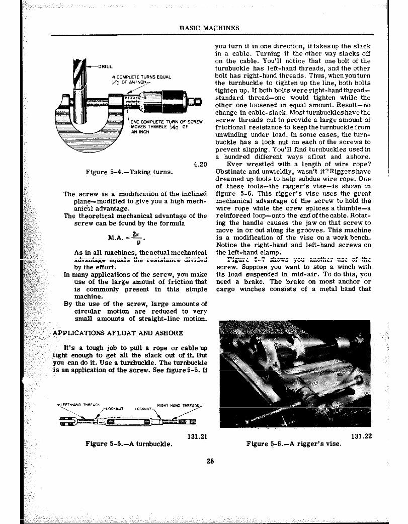
APPLICATIONS AFLOAT AND ASHORE
It’s a tough job to pull a rope or cable up tight enough to get all the slack out of it. But you can do it. Use a turnbuckle. The turnbuckle is an application of the screw. See figure 5-5. If
131.21 131.22 Figure 5-5.-A turnbuckle. Figure $-S.-A rigger’s vise.
20
you turn it in one direction, it takesup the slack in a cable. Turning it the other way slacks off on the cable. You’ll notice that one bolt of the turnbuckle has left-hand threads, and the other bolt has right-hand threads. Thus, whenyouturn the turnbuckle to tighten up the line, both bolts tighten up. If both bolts were right-hand thread- standard thread-one would tighten while the other one loosened an equal amount. Result-no change in cable-slack. Most turnbuckles have the screw threads cut to provide a large amount of frictional resistance to keep the turnbuckle from unwinding under load. In some cases, the turn- buckle has a lock nut on each of the screws to prevent siipping. fou’ii find turnbzkles used in a hundred different ways afloat and ashore.
Ever wrestled with a length of wire rope? Obstinate and unwieldly, wasn’t it?Riggers have dreamed up tools to help subdue wire rope. One of these tools-the rigger’s vise-is shown in figure 5-6. This rigger’s vise uses the great mechanical advantage of the screw to hold the wire rope while the crew splices a thimble-a reinforced loop-onto the end of the cable. Rotat- ing the handle causes the jaw on that screw to move in or out along its grooves. This machine is a modification of the vise on a work bench. Notice the right-hand and left-hand screws on the left-hand clamp.
Figure 5-7 shows you another use of the screw. Suppose you want to stop a winch with its load suspended in mid-air. To do this, you need a brake. The brake on most anchor or cargo winches consists of a metal band that
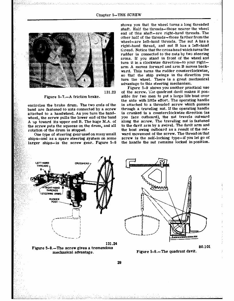
Chapter &THE SCREW
shows you that the wheel turns a long threaded shaft. Half the threads-those nearer the wheel end of this shaft-are right-hand threads. The other half of the threads-those fartherfromthe wheel-are left-hand threads. The nut A has a right-hand thread, and nut B has a left-hand tiwead. Notice that the cross head whichturns the rudder is connected to the nuts by two steering arms. If you stand in front of the wheel and turn it in a clockwise direction-to your right- arm A moves forward and arm B moves back- ward. This turns the rudder counterclockwise, so that the ship swings in the direction you turn tine wheel. There is a great mechanical advantage to this steering mechanism.
131.23 Figure %?.-A friction brake.
encircles the brake drum. The two ends of the band are fastened to nuts connected by a screw attached to a handwheel. As you turn the hand- wheel, the screw pulls the lower end ofthe band A up toward its upper end B. The huge M.A. of the screw puts the squeeze on the drum, and all rotation of the drum is stopped.
One type of steering gear used on many small ships-and as a spare steering system on some larger ships-is the screw gear. Figure 5-8
Figure 5-9 shows you another practical use of the screw. ‘ihe quadrant davit makes it pos- sible for two men to put a large life boat over the side with little effort. The operating handle is attached to a threaded screw which passes through a traveling nut. If the operating handle is cranked in a counterclockwise direction (as
you face outboard), the nut travels outward along the screw. The traveling nut is fastened to the davit arm by a swivel. The davit arm and the boat swing outboard as a result of the Out-
ward movement of the screw. The thread on that screw is the self-locking type-if you let go of the handle the nut remains locked in position.
131.24 Figure %&--The screw gives a tremendous
mechanical advantage. 80.101
Figure 5-9.-The quadrant davit.
29
CHAPTER 6
GEARS
Did you ever take a clock apart to see what made it tick? IX course you came out with some parts left over when you got it back together again. And they probably included a few gear wheels. Gears are used in many machines. Fre- quently the gears are hidden from view in a pro- tective case filled with grease or oil, and you may not see them.
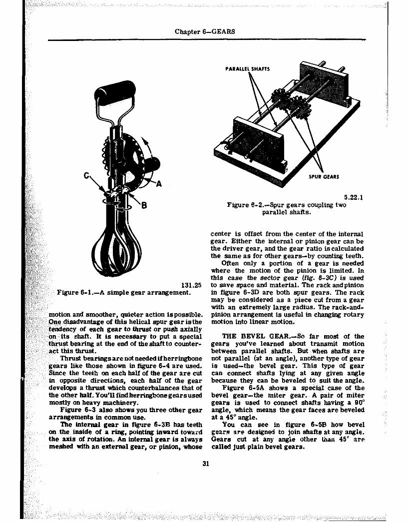
An egg beater gives you a simple demon- stration of the three thtngs that gears do. They can change the direction of motion; increase or decrease the speed of the applied motion; and
;;:;,< magnify or reduce the force which you apply. & f<, Gears also gtve you a positive drive. There can g;; & be, and usually is, creep or slip in a belt drive.
gi;;; But gear teeth are always in mesh, and there can ~)~f~~~:,,, be no creep auf slit. & Follow the directional changes in figure&l. #j& ,, The crank handle is turned in the direction tndi- i,-; cated by the arrow--clockwtse, whenviewed from g&y: &8,:~:; the right. me 32 t& m *= large vefiic. E;;!, :;:,,, wheel A mesh with the 8 teeth on the right- z;:: ;,‘, hand horizontal wheel B, which rotates as indi-
cated by the arrow. Notice that as B turns in a clockwtse dlrecttm, tts teeth mesh with those of wheel C and cause wheel C to revolve in the opposite dlrectim. The rotation of the crank handle has been tmnmnitted by gears to the beater blades, WI&& also r&ate.
Now fiire ad bow the gears change the speed of motim. There are 32 teeth m gear A and 8 teeth m gear B. But the gears mesh, so that me complete revoltion of A results in four Complete revolutions of gear B. And since gear8 B aal C have the same number of teeth, oue revolutim of B results in me revolution of C. Thus the blades revolve four times as fast a8 the crank hamlle.
In chapter I you learned that thtrd-class lever8 Increw qsed at the 8qwn8e of force. The 8ame thh@ bappsus with this egg bsater. Tke nmgnliude of ths force 18 changd. The force requhd tn turn th8 tmndle 18 greater that
the force applied to the frosting by the blades. Therefore a mechanical advantage of less than one results.
TYPES OF GEARS
When two shafts are nc lying in the same straight line, but are parzillel, motion can be transmitted from one to the other by means of spur gears. This setup is shown in figure 6-2.
Spur gears are wheels with mating teeth cut in their surfaces so that one can turn the other without slippage. When the mating teeth are cut so that they are parallel to the axis of rotation, as shown in figure 6-2, the gears are called straight spur gears.
When two gears of unequal size are meshed together, the smaller of the two is usually called a pinion. By unequal size, we mean an unequal number of teeth causing one gear to be of a larger diameter than the other. The teeth, themselves, must be of the same size in order to mesh properly.
The most commonly used type are the stratght spur gears, but quite often you’ll run across another type of spur gear called the hellcal spur gear.
In helical gears the teeth are cut slant- wise acro88 the working face of the gear. One end of the tooth, therefore, lies ahead of the other. In other words, each tooth has a lead- ing end and a trailing end. A look at these gears in figure 6-3A will show you how they’re constmcted.
In the straight spur gears the tiole width of the teeth comes in contact at the same time. But with helical (spiral) gears contact between two teeth starts first at the leading ends ana move8 progressively across the gear facesuntfl the tmlHq end8 are in contact. This M of me&ng actlon keeps the gear8 tn constant contact with one another. Therefore, Ien8 lod
30
Chapter B-GEARS
:,‘:
,T,,~ 131.25
Figure 6-1.-A stmple gear arrangement.
motion and smoother, quieter action ispossible. One dmadvantage of this helical spur gear is the tendency of each gear to thrust or push axially on its shaft. It is necessary to put a special thrust bearing at the end of the shaft to counter- act this thrust.
Thrust bearings are not needed if herringbone gears like those shown in figure 6-4 are used. Since the teetb on each half of the gear are cut in opposite directions, each haIf of the gear develops a thrust which counterbalances that of the other haIf. You’lI findherringbone gears used mostly on heavy machinery.
Figure 6-3 also shows you three other gear arrangements in common use.
The internal gear in ftgure 6-3B has teeth on the inside of a ring, pointing inward toward the axis of rotation. An internal gear is always meshed with an external gear, or pinion, whose
5.22.1 Figure 6-2.-Spur gears coupling two
parallel shafts.
center is offset from the center of the internal gear. Either the internal or pinion gear can be the driver gear, and the gear ratio is calculated the same as for other gears-by counting teeth
Often only a portion of a gear is needed where the motion of the pinion is limited. In this case the sector gear (fig. 6-3C) is used to save space and material. The rack and pinion in figure 6-3D are both spur gears. The rack may be considered as a piece cut from a gear with an extremely large radius. The rack-and- pinion arrangement is useful in changing rotary motion into linear motion.
THE BEVEL G,EAR.-So far most of the gears you’ve learned about transmit motion between parallel shafts. But when shafts are not parallel (at an angle), another type of gear is used-the bevel gear. This type of gear can connect shafts lying at any given angle because they can be beveled to suit the angle.
Figure 6-5A shows a special case of the bevel gear-the miter gear. A pair of miter gears is used to connect shafts having a 90” angle, which means the gear faces are beveled at a 45’ angle.
You can see in figure 6-5B how bevel gears are designed to join shafts at any angle. Gears cut at any angie other than 45” are called just plain bevel gears.
31
,,
BASIC MACHINES
NEAR MOTION
Figure 6-3.-Gear types. 5.23:.24
The gears shown in figure 6-5 are called ,,,, straight bevel gears, because the whole width
of each tooth comes io contact with the mating f;: tooth at the same time. However, you’ll also ‘,,‘: rue across spiral bevel gears with teeth cut _:: so as to have advanced and trailing ends.
Figure 6-6 shows you what spiral bevel gears look like. They have the same advantages as
522.3 Figure 6-4.-Herringbone gear.
other spiral (helical) gears--less lost motion and smoother, quieter operation.
THE WORM AN’D WORM WHEEL.-Worm and worm-wheel combinations, like those in figure 6-7, have many uses and advantages. But it’s better to understand their operating theory before learning of their uses and ad- vantages.
Figure 6-IA shows the action of a single- thread worm. For each revolution of the worm,
A. MITER GEAR B. BEVEL GEAR
5.22.4 Figure 6-5.-Bevel gears.
32
Chapter B-GEARS
5.22.6 Figure 6-6.-Spiral bevel gears.
the worm wheel turns one tooth. Thus if the worm wheel has 25 teeth the gear ratio is 25:l.
Figure 6-7B shows a double-thread worm. For each revolution of the worm in this case, the worm wheel turns two teeth. That makes the gear ratio 25:2 if the worm wheel has 25 teeth.
Likewise, a triple-threaded wormwouldturn the worm wheel three teeth per revolution of the worm.
A worm gear is really a combination of a screw and a spur gear. Tremendous me- chanical advantages can be obtained with this arrangement. Worm drives can also be de- signed so that only the worm is the driver-the
spur cannot drive the worm. On a hoist, for example, you can raise or lower the load by pulling on the chain which turns the worm. But if you let go of the chain, the load caonot drive the spur gear and let the load drop to the deck. This is a non-reversing worm drive.
CHANGING DIRECTION WITH GEARS
No doubt you know that the crankshaft in an automobile engine can turn inonly onedirection. If you want the car to go backwards, the effect of the engine’s rotation must be reversed. This is done by a reversing gear in the transmission, not by reversing the direction in which the crankshaft turns.
A study of figure 6-6 will show you how gears are used to change the direction of motion. This is a schematic diagram of the sight mountson a Navy gun. If you crhnk the range-adjusting handle A in a clockwise direction the gearB di- rectly above it is made to rotate in a counter- clockwise direction. This motion causes the two pinions C and D on the shaft to turn in the same direction as gear B against the teeth cut in the bottom of the table. The table is tipped in the direction indicated by the arrow.
As you turn the deflection-adjusting handle E in a clockwise direction the gear F directly above it turns in the opposite direction. Since the two bevel gears G and H are fixed on the
SINGLE-THREAD WORM oo”IE-THREAD WORM
Figure 6-7.-Worm gears.
33
5.22.9
BASIC MACHINES
Now, if you turn A at a speed of four revolu- tions per second, B will be rotated at one revolution per second. Wheel C also moves at one revolution per second, and causes D to turn at two revolutions per second. You get out two revolutions per second after having put in four revolutions per second. Thus the overall speed reduction is 2/4-or li’2-which means that you got half the speed out of the last driven wheel that you put into the first driver wheel.
You can solve any gear speed-reduction problem with this formula-
131.26 Figure 6-6.-Gears change direction of
applied motion.
zjt:’ shaft with F, tbeyalsoturn. These bevel gears, f& “’ meshing with the horizontal bevel gears I and & ‘J, cause I and J to swtng the front ends of the $#%‘:: telescopes to the right. Thus with a simple
~~,~~,.::~y”ern of gears, it is possible to keep the two &z;:,,: telescopes pointed at a moving target. In this ~~~~“‘~na, many other practical applications, gears $& serve one purpose-to change the direction of &:-;,-;: ,,:_,, motion.
As you’ve already seen in the egg-beater, ~~~~~~:~:(~l:gears can be used to change the speed of motion. ;;;j::;,,;-~ ,Another example of this use of gears is found $;!,?:; ;$: your clock or watch. The, mainspring slowly ::-c’:‘~ :,,unv!inds and causes the hour hand to make one ,I[: i!‘):, revolution in 12 b:;urs. ,, Through a series-or :;!;;;;j; tram-of gears, the minute hand makes one ;,;~‘~:~ : revolution each hour, while the second, hand ,: ,~ ~.GL.“‘“” “..” A once peF mhte*
-9 will helo vou to understand how
where
S 1= speed of first shaft in train S 2 = speed of last shaft in train Tl = product of teeth on all drivers T2 = product of teeth on all driven gears Now use the formula on the gear train of
ficure 6-6.
T1 10 x 20 s2 = s1 = xq= 4x40=
600 400 _ - 2 revs. per sec.
40 TEETH
IO TEETH\ DRIVER
wheel B. Wheel A will ,have to,rotate,four ‘,~, times ‘to cause B to make one revolution. IO T
.y fined on the same shaft with
Figure 6-B.-Gears can change speed of applied motion.
Chapter B-GEARS
Almost any increase or decrease in speed can be obtained by choosing the correct gears for the job. For example, the turbines on a ship have to turn at high speeds-say 5600 rpm- if they are going to be efficient. But the propellers, or screws, must turn rather slowly- say 195 rpm-to push the ship ahead with maximum efficiency. So, a set of reduction gears is placed between the turbines and tbe propeller shaft.
teeth, whichmeshwiththe6Oteethonthe internal spur gear. You will find it easier to figure the mechanical advantage of tbis machine if you think of it as two machines.
First, figure out what the gear and pinion do for you. The theoretical mechanical advantage of any arrangement of two meshed gears can be found by the following formula-
When two external gears mesh, they rotate in opposite directions. Often you’ll want to avoid this. Put a third gear, called an idler, between the driver and the driven gear. But don’t let this extra gear confuse you on speeds. Just neglect the idler entirely. It doesn’t change the gear ratio at all, and the formula still applies. The idler merely makes the driver and its driven gear turn in the same direction. Figure 6-10 will show you how this works.
M. A. (theoretical) = r a
In which, To = number of teeth on driven gear;
In this case, To = 60 and TI = 10. Then,
M. A. (theoretical) = c = iij- = 6
MAGNIFYING FORCE WITII GEARS
Gear trains are used to increase the me- chanical advantage. In fact, wherever there is a speed reduction, the effect of the effort you apply is multiplied. Look at the cable winch in figure 6-11. The crank arm is 30 inches long, and the drum on which the cable is wound has a 15”inch radius. The small pinion gear has 10
Now, for the other part of the machine, which is a simple wheel-and-axle arrangement con- sisting of the crank arm and the drum. The theoretical mechanical advantage of this can be found by dividing the distance the effort moves- 2vR-in making one complete revolution, by th? distance the cable is drawn up in one revolution of the drum-2vr.
Id. A. (theoretical) = +$ = $ = g= 2
SAME DIRECTION /
Figure 6-10.-An idler gear.
35
TO
Ta= number of teeth on driver gear.
To -60
12.55
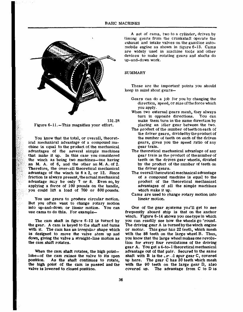
131.28 Figure 6-ll.-This magnifies your effort.
You know that the total, or overall, theoret- ical mechanical advantage of a compound ma- chine is equal to the product of the mechanical advantages of the several simple machines that make it up. In this case you considered the winch as being two machines-one having an M. A. of 6, and the other an M. A. of 2. Therefore, the over-all theoretical mechanical advantage of the winch is 6 x 2, or 12. Since friction is always present, theactual mechanical advantage may be only 7 or 8. Even so, by applying a force of 100 pounds on the handle, you could lift a load of ‘700 or 800 pounds.
You use gears to produce circular motion. But you often want to change rotary motion into up-and-down or linear motion. You can use cams to do this. For example-
The cam shaft in figure E-12 is turned by the gear. A cam is keyed to the shaft and turns with it. The cam has an irregular shape which is designed to move the valve stem up and down, giving the valve a straight-line motion as the cam shaft rotates.
When the cam shaft rotates, the high point- lobe-of the cam raises the valve to its open position. As the shaft continues to rotate, the high point of the cam is passed and the valve is lowered to closed position.
BASIC MACHINES
A set of cams, two to a cylinder, driven by timing gears from the crankshaft operate the exhaust and intake valves on the gasoline auto- mobile engine as shown in figure 6-13. Cams are widely used in machine tools and other devices to make rotating gears and shafts do up-and-down work.
SUMMARY
These are the important points you should keep in mind about gears-
Gears can do a job for you by changing the direction, ‘speed, or sizeoftheforce which you apply.
When two external gears mesh, they always turn in opposite directions. You can make them turn in the same direction by placing an idler gear between the two.
The product of the number of teeth on each of the driver gears, divided by the product of the number of teeth on each of the driven gears, gives you the speed ratio of any gear train.
The theoretical mechanical advantage of any gear train is the product of thsnumberof teeth on the driven gear wheels, divided by the product of the number of teeth on the driver gears.
The overall theoretical mechanical advantage of a compound machine is equal to the product of the theoretical mechanical advantages of all the simple machines which make it up.
Cams are used to change rotary motion into linear motion.
One of the gear systems ~00’11 get to see frequently aboard ship is that on the anchor winch. Figure 6-14 shows you one type in which you can readily see how the wheels go ‘round. The driving gear A is turned by the winch engine or motor. This gear has 22 teeth, which mesh with the 88 teeth on the large wheel B. Thus, you know that the large wheel makes one revolu- tiou for every four revolutions of the driving gear A. You get a4-to-1 theoreticalmechanical advantage out of that pair. Secured to the same shaft with B is the L s-. ,.rl spur gear C, covered up here. The gear C has 30 teeth which mesh with the 90 teeth on the large gear D, also covered up. The advantage from C to D is
36
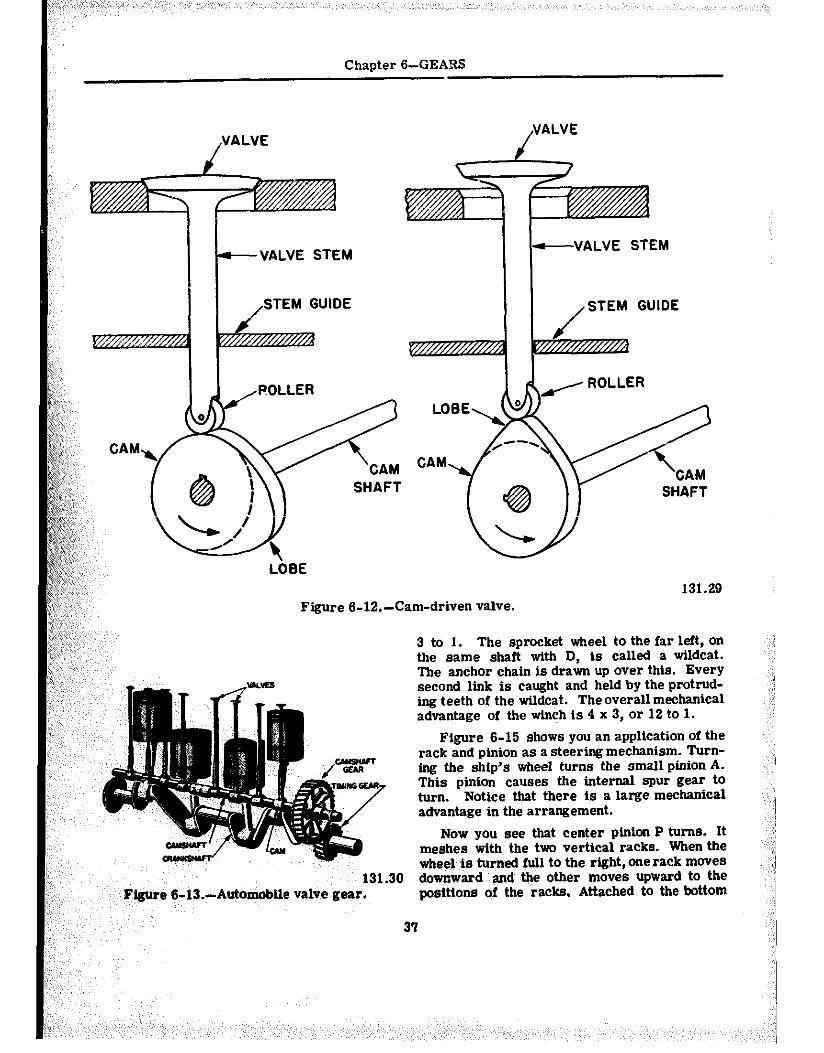
Chapter B-GEARS
VALVE
,,
,::’ ,, ,:,; ‘s,:,
( @) ys: “““?/
,~,,:~~;; ‘, q-& 0
LOBE ,A,’ ),,,, ,::,, Figure 6-12.-Cam-driven valve.
c VALVE STEM
POLLER d LOBE,
-VALVE STEM
SHAFT
131.29
131.30 FIgwe 6-13.-Automobtle valve gear.
3 to 1. The sprocket wheel to the far left, on the same shaft with D, is called a wildcat. The anchor chain is drawn up over this. Every second link is caught and held by the protrud- ing teeth of the wildcat. The overall mechanical advantage of the winch is 4 x 3, or 12 to 1.
Figure 6-15 shows you an application of the rack and pinion as a steering mechanism. Turn- ing the ship’s wheel turns the smsll pinion A. This pinion causes the internal spur gear t0 turn. Notice that there is a large mechanical advantage in the arrangement.
Now you see that center pinion P turns. It meshes with the two vertical racks. When the wheel is turned full to the right, onerack moves downward and the other moves upward to the positions of the racks. Attached to the bottom
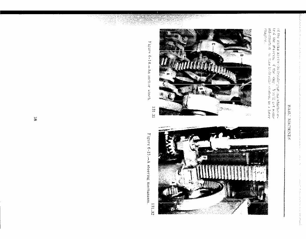
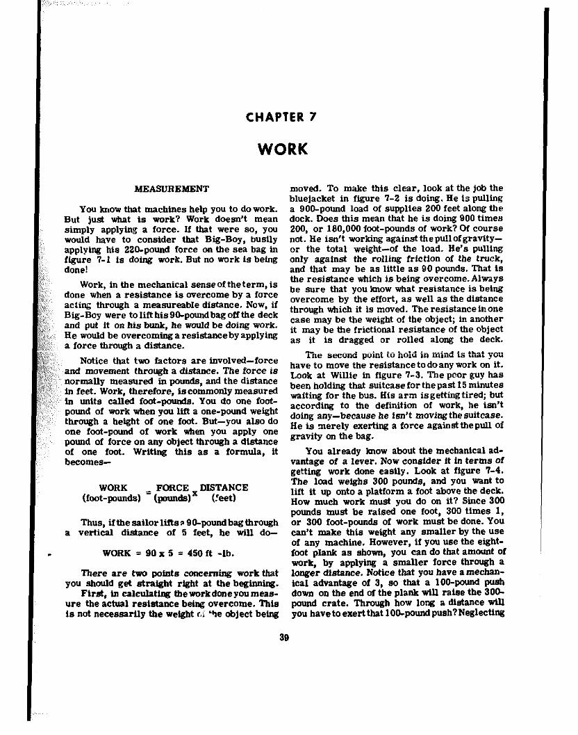
CHAPTER 7
WORK
b%EASLJRBMKNT
You know that machimes help you to do work. But just what is work? Work doesn’t mean simply applytng a force. If that were so, you would have to consider that Big-Boy, busily applying his 22O-pound force on the sea bag in figure 7-l is doing work. But no work is being done!
Work, in the mechanical sense of theterm, is done when a resistance is Overcome by a force acting through a measureabIe distance. Now, if Big-Boy were to lift his 9O-poundbag off the deck and put it on his bunk, he would be doing work. He would be overcoming a resistance by applying a force through a distance.
Notice that two factors are involved-force and movement through a distance. The force is normally measured in pounds, and the distance in feet. Work, therefore, is commonly measured
‘~ in units called foot-pounds. You do one foot- pound of work when you lift a one-pound weight through a height of one foot. But-you also do one foot-pound of work when you apply one pound of force on any object through a distance of one foot. Writing this a5 a formula, it becomes-
WORK FORCE DISTANCE (foot-p0unds) = (p0u1&)~ (?eet)
Thus, ifthe sailor liise 9O-poundbagthrough a vertical distance of 5 feet, he will do-
WORK = 90 x 5 = 450 ft -lb.
There are two points c0ncemfng work that you should get straight right at the beginning.
First, in cslculstiqg tbeworkdoneyoumeas- we the actual resintance being overcome. This is not necessarily the weight ci “re object being
moved. To make this clear, look at the job the bluejacket in figure 7-2 is doing. He is pulling a 9OO-pound load of supplies 200 feet along the dock. Does this mean that he is doing 900 times 200, or 180,000 foot-pounds of work? Of course not. He isn’t working against the pull of gravity- or the total weight-of the load. He’s pulling only against the rolling friction of the truck, and that may be as little as 90 pounds. That is the resistance which is being overeome.Always be sure that you know what resistance is being overcome by the effort, as well as the distance through which it is moved. The resistance in one case may be the weight of the object; in another it may be the frictional resistance of the object as it is dragged or rolled along the deck.
Ttne second point to hoid in mind is that yott have to move the resistance to do any work on it. Look at Willie in figure ‘7-3. The poor guy has been holding that suitcase for the past 15 minutes waiting for the bus. His arm is getting tired; but according to the definition of work, he isn’t doing any-because he isn’t moving the suitcase. He is merely exerting a force againstthepull Of gravity on the bag.
You already know about the mechanical ad- vantage of a lever. Now consider it in terms of getting work done easily. Look at figure T-4. The load weighs 300 pounds, and you want t0 lift it up onto a platform a foot above the deck. How much work must you do on it? Since 300 pounds must be raised one foot, 300 times 1, or 300 foot-pounds oi work must be done. You can’t make this weight any smaller by the use of any machine. However, if you use the eight- foot plank as shown, you can do that amount Of work, by applying a smaller force through a longer distance. Notice that you have a mecban- ical advantage of 3, 50 that a lOO-pound push down on the end of the plank will raise the 3OO- pound crate. Through how long a distance will you havetoexert that lOO-poundpush?Neglecting
38
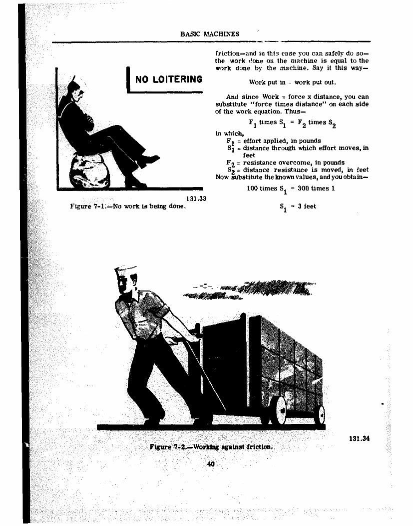
BASIC MACHINES _.~
NO LOITERING
131.33 Figure T-I.-No work is being done.
friction-and in this case you can safely do so- the work t?one on the machine is equal to the work done by the machine. Say it this way-
Work put in :: work put out.
And since Work = force x distance, you can substitute “force times distance” on each side of the work equation. Thus-
Fl times Sl = F3 times S3
in which, Fl = effort applied, in pounds Sl = distance through which effort moves, in
feet F3 = resistance overcome, in pounds S3 = distance resistance is moved, in feet
Now substitute the known values, and you obtain-
100 times S, = 300 times 1
mm!m
G2.-Wmklng agatmt frlctlm.
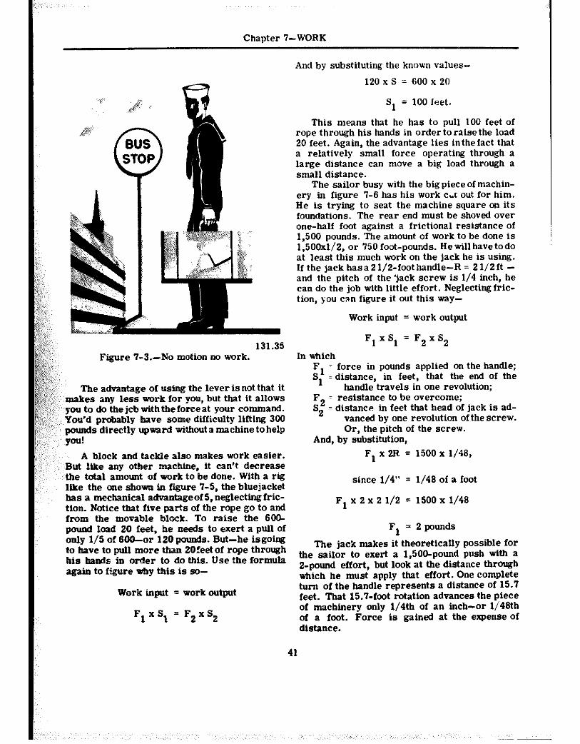
Chapter ‘I-WORK
131.35 Figure ‘7-3.-f% motion no work.
The advantage of using the lever is not that it ,makes any less work for you, but that it allows you to do thejobwithtbeforceat your command. You’d probably have some difficulty lifting 306 pounds directly upward wttbout a machine to help p”!
A block and tac,kle also makes work easier. But ltke any other machme, it can’t decrease the total amount of work to be done. With a rig ltke the one shown in figure 7-5, the bluejacket has a mechanical advantageof 5,neglectingfric- tion. Notice that five parts of the rope go to and from the movable block. To raise the 600- pound load 20 feet, he needs to exert a pull of only l/5 of 666-or 120 pounds. But-he isgoing to have to pull more than 2Ofeet of rope through his hands tn order to do this. Use the formula again to figure why this is so-
Work input = work output
F1xS, = F2xS2
And by substituting the known values-
120 x s = 600 x 20
Sl = 100 feet.
This means that he has to pull 100 feet of rope through his hands in order to raise the load 20 feet. Again, the advantage lies inthefact that a relatively small force operating through a large distance can move a big load through a small distance.
The sailor busy with the big piece of machin- ery in figure ‘J-6 has his work c~.t out for him. He is trying to seat the machine square on its foundations. The rear end must be shoved over one-half foot against a frictional resistance of 1,500 pounds. The amount of work to be done is 1,500x1/2, or 750 foot-pounds. He will have todo at least this much work on the jack he is using. If the jack has a 2 l/2-foot handle-R = 2 l/2 ft - and the pitch of the ‘jack screw is l/4 inch, he can do the job with little effort. Neglectingfric- tion, you can figure it out this way-
Work input = work output
Fl xSl = F2xS2
In which Fl = force in pounds applied on the handle; S1 : distance, in feet, that the end of the
handle travels in one revolution; F2 * resistance to be overcome; S2 = distance in feet that head of jack is ad-
vanced by one revolution of the screw. Or, the pitch of the screw.
And, by substitution, F1 x 2R = 1500 x l/46,
since l/4” = l/46 of a foot
Fl x 2 x 2 l/2 = 1500 x l/46
F1 = 2 pounds
The jack makes it theoretically possible for the sailor to exert a 1,506-pound push with a 2-pound effort, but look at the distance through which he must apply that effort. One complete turn of the handle represents a distance Of 15.7 feet. That 15.7-foot rotation advances the piece of machinery only 1/4th of an inch-or 1/46th of a foot. Force is gained at the expense of distance.
41
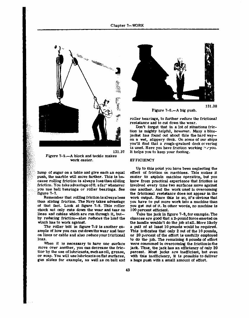
Chapter 7-WORK
:
,: _ Q&,, (c- .,. ?,, 1.
th
7, ~~~~;~~,,,~ ‘q ~
9 <I”
Figure 7-5.-A block and tackle makes work easier.
lump of sugar on a table and give each an equal push, the marble will move farther. This is be- cause rolling friction is always 1~~s than sliding friction. You take advantage of tt. s fact whenever you use ball bearings or roller bearings. See figure 7-7.
Remember that rolling friction is always less than sliding friction. The Navy takes advantage of that fact. Look at figure .7-K This roller chock not only cuts down the wear and tear on lines and cables which are run through it, but- by reducing friction-also reduces the load the winch has to work against.
The roller bitt in figure 7-9 is another ex- ample of how you cah cut down the wear and tear on lines or cable and also reduceyourfrictional loss.
when it is necessary to have one surface move over another, you can decrease the fric- tier by the use of lubricants, suchas oil, grease, or soap. You will use lubricants on flat surfaces, gun slides for example, as well as on ball and
43
Figure 7-6.-A big push. 131.38
roller bearings, to further reduce the frictional resistance and to cut down the wear.
Don’t forget that in a lot of situations fric- tion is mighty helpful, however. Many a blue- jacket has found out about this the hard way- on a wet, slippery deck. On some of our ships you’ll find that a rough-grain4 deck covering is used. Here you have friction working ?.r you. It helps you to keep your footing.
EFFICIENCY
Up to this point you have been neglecting the effect of friction on machines. ‘Ibis makes it easier to explain machine operation, but you know from practical experience that friction is involved every time two surfaces move against one another. And the work used in overcoming the frictional resistance does not appear in the work output. Since this is so, it’s obvious that you have to put more work into a machine than you get out of it. In other words, no machine is 100 percent efficient.
Take the jack in figure 7-6, for example. The chances are good that a 2-pound force exerted on the handle wouldn’t do the job at ail. More likely a pull of at least 10 pounds would be required. This indicates that only 2 out of the IO pounds, or 20 percent of the effort is usefully employed to do the job. The remaining 8 pounds of effort were consumed in overcoming the friction in the jack. Thus, the jack has an efficiency of only 20 percent. Most jacks are inefficient, but even with tbis inefficiency, it is possible to deliver a huge push with a small amount of effort.
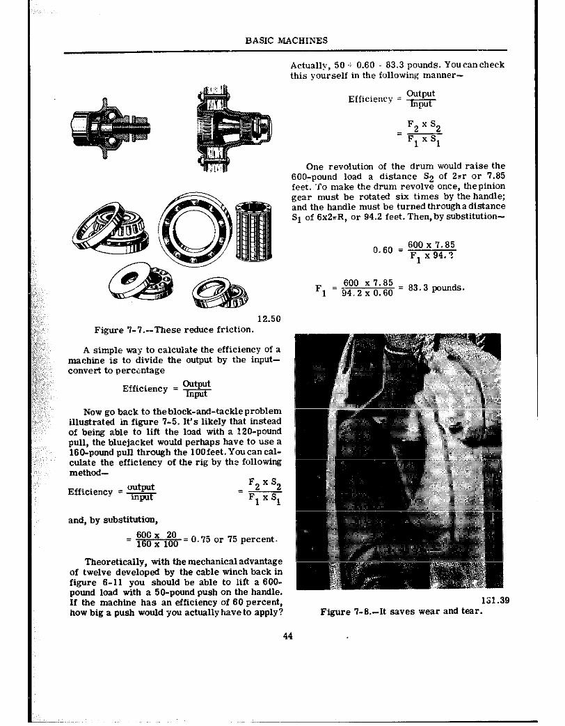
BASIC MACHINES
12.50 Figure 7-i’.-These reduce friction.
A simple way to calculate the efficiency of a machine is to divide the output by the input- convert to percentage
Efficiency = s
Now go back to theblock-and-tackleproblem illustrated in figure 7-5. It’s likely that instead of being able to lift the load with a 120-pound pull, the bluejacket would perhaps have to use a 160-pound pull through the 100feet.Youcancal- culate the efficiency of the rig by the following method-
Efficiency = $$- F2 x s2 = Fl x Sl
and, by substitution,
= 600 x 20 = 16ox 1oo 0.75 or 75 percent.
Theoretically, with the mechanical advantage of twelve developed by the cable winch back in figure 6-11 you should be able to lift a 600- pound load with a 50-pound push on the handle. If the machine has an efficiency of 60 percent, how big a push would you actually have to apply?
Actually, 50 + 0.60 = 83.3 pounds. Youcancheck this yourself in the following manner-
Efficiency = $$$
F2 x s2 = Fl x Sl
One revolution of the drum would raise the 6OO:pound load a distance S2 of 2nr or 7.65 feet. ‘To make the drum revolve once, the pinion gear must be rotated six times by the handle; and the handle must be turned through a distance Sl of 6x2rR, or 94.2 feet. Then, by substitution-
o.60 = 600 x 7.65 Fl x 94.2
F1 =i34.2xO.60 ’ 600 X7.85 = 63 3 p,,unds.
131.39 Figure 7-6.-R saves wear and tear.
44
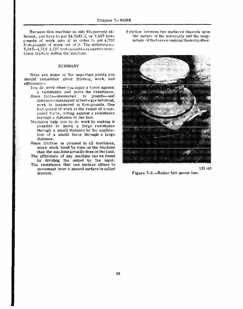
Chapter ‘i--WORK
Because this machine is only G&percent ef- ficient, you kve to put 94.2x84.3, <>r 7,647 foot- pounds of work into it in order to get 4,710 foot-pounds of work outs of it. The differenee- 7,847-4,710 3,137 foist-p,,u~d~-isusedtoorer- cmie friction within the machine.
Here are some oi the important points you should remember abmt friction, work. and efficiency-
You dc sork when yciu apply a f3rce against a r&stance and move the resistance.
Since force--measured in pounds-and distance- measured in feet-are involved, wcrk is measured in foot-pounds. One foot-poured of work in the result of a me- ;xxnrd force, acting against a resistance through a distance of one foot.
Mxhines help you to do work by making it possible tti move a large resistance through a smalP distance by the applica- tion of a small force through a large distance.
Since friction is present in all machines, more work must be done on the machine thar, the machine actually does on the load.
The efficiency of any machine ~a.1 be found by dividing the output by the input.
The resistance that one surface offers to movement over a second surface is called friction.
Friction between two surfaces depends upon the nature of the materials and the mag- nitude ~~ftlleforces:lushing them together.
Figure 7-9.-Roller bitt saves line.
45
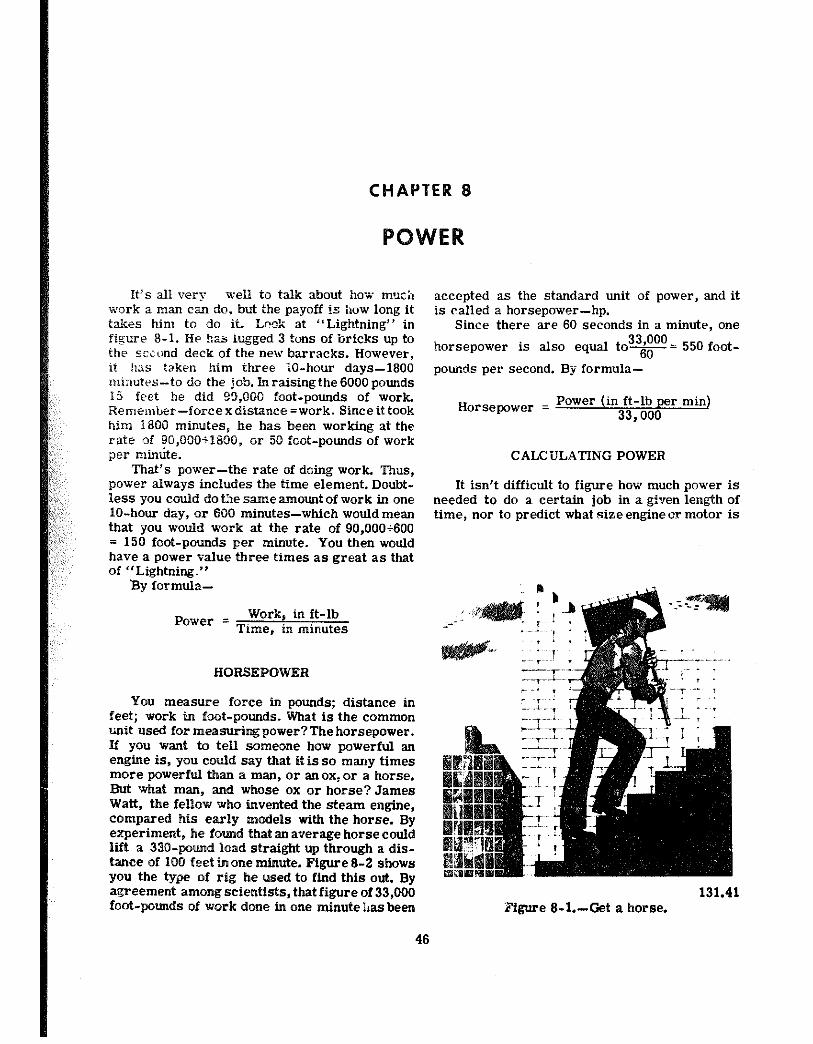
CHAPTER 8
H’S all very %dl i0 talk about ho** tt?Jc;l
work a man can do, but the payoff is how long it takes him to do it. Look at “Lightning” in figure 8-I. He has iugged 3 tons of bricks up to the sciond deck of the new barracks. However, it Ius raken him three X-hour days-1800 minutes-to do the job. hiraisingthe 6000 pounds 15 feet he did 99,550 foot-pounds of work, Remember-forcexdistance=work. Sinceittook him 1800 minutes, he has been working at the rate of 90,000+1850, or 5.9 foot-pounds of work per mimite.
That’s power-the rate of doing work. Thus, power always includes the time element. Doubt- less you could do the same amount of work in one lo-hour day, or 850 minutes-which would mean that you would work at the rate of 90,000+600 = 150 foot-pounds per minute. You then would have a power value three times as great as that of “Lightning.”
By formula-
Power = Work, in ft-lb Time, in minutes
RORSEPOWER
You aneasure force in pounds; distance in feet; work in foot-Pounds. What is the common unit used for measuring power? The horsepower. If you want to tell someone how powerful an engine is, you could say that it is so many times more powerful than a man, or an ox, or a horse. But what man, and whose ox or horse? James Watt, the fellow who invented the steam engine, compared his early models with thehorse. By experiment, he found that an average horsecould lift a 33%pound load straight up through a dis- tance of 160 feet inone minute. Figure 8-2 shows you the type of rig he used to find this out. By agreement among scientists, that figure of 33,000 foot-pounds of work done in one minute has been
accepted as the standard unit of power, and it is called a horsepower-hp.
Since there are 60 seconds in a minute, one
horsepower is also equal to3T= 550 foot-
pounds per second. By formula-
Horsepower = Power (in ft-lb per min) 33,000
CALCULATING POWER
It isn’t difficult to figure how much power is needed to do a certain job in a given length of time, nor to predict what size engine or motor is
131.41 Figure 8-l.-Get a horse.
46
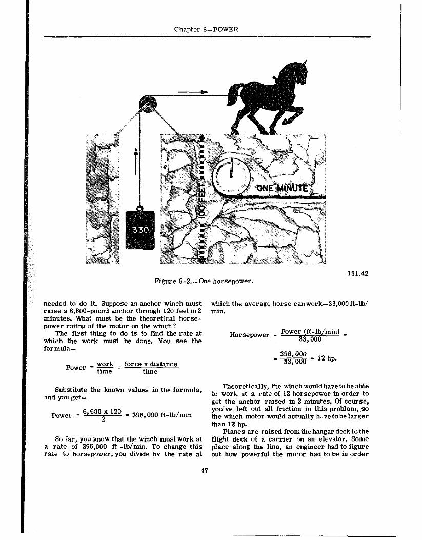
Chapter L-POWER
Figure 8-2.-One horsepower. 131.42
needed to do it. Suppose an anchor winch must which the average horse canwork-33,000 ft-lb/ raise a 6,600-pound an&or through 120 feet in 2 min. minutes. Whaf must be the theoretical horse- power rating of the motor on the winch?
The first thing to do is to find the rate at which the work must be done. You see the
Horsepower = Power (ft-lb/minj = 33,000
formula-
WOI-k Power = time = force x distance time
396,000 = 33,000 = 12 hp.
Substitute the known values in the formula, Theoretically, the winch would have to be able
and you get- to work at a rate of 12 horsepower in order to at the anchor raised in 2 minutes. Of course.
power = 69600 ’ I20 = 396 000 ft-lb/min ;&w left out all friction in this problem, .so
2 t the winch motor would actually h,ve to be larger than 12 hp.
Planes are raised from the hangar decktothe So far, you lorow that the winch mustwork at flight deck of a carrier on an elevator. Some
a rate of 386,000 ft -lb/min. To change this place along the line, an engineer had to figure rate to horsepower, you divide by the rate at out how powerful the motor had to be in order
47
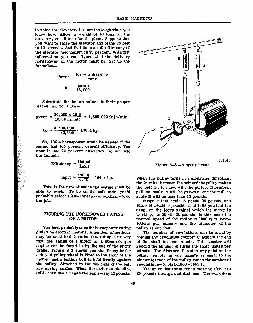
BASIC MACIIINES
to raise the elevator. It’s not tootough when you know how. Allow a weight of 10 tons for the elevator, and 5 tons for the plane. Suppose that you want to raise the elevator and plane 25 feet in 10 seconds. And that the overall efficiency of the elevator mechanism is 70 percent. With that information you can figure what the delivery horsepower of the motor must be. Set up the formulas-
Power = force x distance time
Substitute the known values in their proper places, and you have-
power = 3m = 4.500,OOO ft lb/min.
hp = 4,500,000 33,000
= 136.4 hp.
SO, 136.4 horsepower would be needed if the engine had 100 percent overall efficiency. You want to use 70 percent efficiency, so you use the formula-
Efficiency = s
hpd = K = 194.8 hp.
This is the rate at which the engine must be able to work. To be on the safe side, you’d probably select a 200-horsepower amdliary todo the job.
FIGURING TIIE HORSEPOWER RATING OF A MOTOR
You have probably seen the horsepower rating plates on electric motors. A number of methods may be used to determine rhts rating. One way that the rating of a motor or a steam or gas engine can be found is by the use of the prony brake. Figure 8-3 shows you the Prony brake setup. A pulley wheel is fixed to the shaft of the motor, and a leather belt is held firmly against the pulley. Attached to the two ends of the belt are spring scales. When the motor is standing still, each scale reads the same-say 15pounds.
48
131.43 Figure 8-3 .-A prony brake.
When the pulley turns in a clockwise direction, the friction between the belt and the pulley makes the belt try to move with the pulley. Therefore, pull on scale A will be greater, and the pull on scale B will be less then 15 pounds.
Suppose that scale A reads 25 pounds, and scale B reads 5 pounds. That tells you that the drag, or the force against which the motor is working, is 25-5 120 pounds. In this case the normal speed of the motor is 1800 rpm (revo- lutions per minute! and the diameter of the pulley is one foot.
The number of revolutions can be found by holding the revolution counter C against the end of the shaft for one minute. This counter will record the number of turns the shaft makes per minute. The distance D which any point on the pulley travels in one minute is equal to the circumference of the pulley times thenumber of revolutions-3.14~1~1800 =5652 ft.
You know that the motor is exerting a force of 20 pounds through that distance. The work done
.POWER
has a 1/16&p motor; a washing machine a l/4- hp motor.
SUMMARY
Chapter 6- Chapter tl-POWER
in one minute is equal to the force times the in one minute is equal to the force times the has a 1/16&p motor; a washing machine a l/4- distance, or work = FxD = 20x5,652= 113,040 distance, or work = FxD = 20x5,652= 113,040 hp motor. ft -Lbjmin. Change this to horsepower- ft -Lbjmin. Change this to horsepower-
SUMMARY
~ = 3.43 hp. ~ = 3.43 hp. There are two important points for you to remember about Power-
Power is the rate at which work is done. The unit in which power is measured is the
Here are a few ratings for motors or engines Here are a few ratings for motors or engines horsepower, which is equivalent to working at a with which you are fan&ar-an electric mixer with which you are fan&ar-an electric mixer rate of 33,000 ft-lbper min, or 550 ft-lb per sec.
There are two important points for you to remember about Power-
Power is the rate at which work is done. The unit in which power is measured is the
horsepower, which is equivalent to working at a rate of 33,000 ft-lbper min, or 550 ft-lb per sec.
49
CHAPTER 9
FORCE AND PRESSURE
By this time you should have a pretty good idea of what aforce is. A force is a push or a pull exerted on-or by-an object. You appk$ a force on a machine, and the machine in turn transmits a force to the load. Men and machines, however, are not the only things that can exert forces. If yku’ve been out in a sailboat you know that the wind can exert a force. Further, youdon’t have to get knocked on your ear more than a couple of times by the waves to get the idea that water, too, can exert a force. As a matter of fact, from reveille to taps you are almost constantly either exerting forces or resisting them. That’s the reason you are pooped when you hit the sack.
MEASURING FORCES
You’ve had a lot of experience in measuring forces. You can estimate or “guess” the weight Of a package you’re going to mail by “hefting” it. Or you can put it on a scale to find its weight accurately. Weight is a common term that tells you how much force or pull gravity is exerting on the object.
You can readily measure force with aspring scale. An Englishman named Hooke discovered that if you hang a l-pound weight ona spring, the spring stretches a certain distance. A 2-pound weight will extend the spring just twice as far, and 3 pounds will lengthen it three times as far as the l-pound weight did. Right there is the makings of the spring scale. AU you need to do is attach a pointer to the spring, put a face on the scale, and mark on the face the positions of the pointer for various loads in pounds or ounces.
This type of scale can be used to measure the pull of gravity-the weight-of an object, or the force of a pull exerted against friction, as shown in figure 9-l. Unfortunately, springs get tired, just as you do. When they get old, they don’t always snap back to the original position. Hence an old spring or an overloaded spring will give inaccurate readings.
HONEST WEIGHT-NO SPRINGS
Because springs do get tired, other types of force-measuring devices are made. You’ve seen the sign, “Honest Weight-No Springs”, on the butchershop scales. Scales of this type are shown in figure 9-2. They are applications of first-class levers. The one shown in figure 9-2A is the simplest type. Since the distance from the fulcrum to the center of each platform is equal, the scale is balanced when equal weights are placed on the platforms. With your knowl- edge of levers, you will he able to figure out how the steel yard shown in figure 9-2Boperates.
PRESSURE
Have you ever tried to walk on crusted snow that would break through when you put your weight on it? But you could walk on the same snow if you put on snowshoes. Further, you know that snowshoes do not reduce your weight-they merely distribute it over a larger area. In doing this, they reduce the pressure per square inch. Figure out how that works. If you weigh 160 pounds, that weight, or force, is more or less evenly distributed by the soles of your shoes. The area of the soles of an average man’s shoes is roughly 60 square inches. Each one of those square inches has to carry 160+60=2.6 pounds of your weight. Since 2.6 pounds per square inch is too much for the snow crust, you break through.
When you put on the snowshoes, youdistribute your weight over an area of approximately 900 sq hr.-depending, of course, on the size of the snowshoes. Now the force on each one of those square inches is equal to only 160+900=0.16 pound. The pressure on the snow has been de- creased, and the snow can easily support you.
Pressure is force per unit area-and is measured, in pounds per square inch-“psi.” With snowshoes on, you exert a pressureof0.16
50
Chapter 9-FORCE AND PRESSURE
131.44 figure g-I.-You can measure force with a scale.
psi. To calculate pressure, divide the force by the area over which the force is applied. The formula is-
Pressure, in psi = Force, in lb Area, in sq in
To get this idea, follow this problem. A tani: for holding fresh water ahoard a ship is 10 feet long, 6 feet wide, and4feetdeep. It holds, there- fore, 10x6~4, or 240 cubic feet of water. Each cubic foot of water weighs aboLt 62.5 pounds. The total force tending to push the bottom out of the tank is equal to the weight of the water- 240x62.5, or 15,000 lb. -What is the pressure on the bottom? Since the weight is evenly distributed
on the bottom, you apply the formula P=gand
substitute the proper values for F and A. In thil case, F=15,000 lb, and the area of the bottom in
51
square inches is 10x6~144, since 144 sq in.=1 sq ft.
PC. 15,000 1o x 6 x 144 = 1’74 psi
Now work out the idea in reverse. You live at the bottom of the great sea of air which sur- rounds the earth. Because the air has weight- pa:,@ @a 0” &tie &, $.30-the air exerts a force on every object which it surrounds. Near sea level that force on an area of 1 square inch is roughly 15 pounds. Thus, the air-pressure at sea level is about 15 psi. The pressure gets less uld less as you go up to higher altitudes.
With your finger, mark out an area of one square foot on your chest. What is the total force which tends to push in your chest?Againuse the
formula P =$. Now substitute 15 psi for P, and
for A use 144 sq. in. Then F=144x15, or 2160 lb. The force on your chest is 2160 lb per square foot--more than a ton pushing against an areaof
BASIC MACHINES
Figure I)-2.-Balances.
1 sq ft. If there were no air inside your chest to equal pressure in all directions. Figure 9-3 pzsh outward with ths san~e pressure, you’d be shows that. Whether the hole is 51 the top, the squashed flatter thsn a bride’s biscuit. bottom, or in one of the sides of a submarine,
the water pushes in through the hole. MEASURJi’IG PRESSURE In many jobs aboard ship, it is necessary to
Fluids-which include both liquids and know the presses exerted by gas or a liquid. gases-exert pressure. A fluid at rest exerts For example, it is important at all times to know
131.45 Figure 9-3.-Fluids exert pressure in all directions.
52
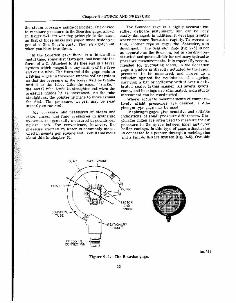
Chapter 9-FORCE AND PRESSURE
the steam pressure inside of aboiler. One device to measure pressure isthe Bourdcn gage, shown in figure 9-4. Its workkg prizci-,‘,e is the same as that of those sntakeEike paper tubes which you get at a New Year’s party-. They straighten out when you blow illto them.
In the Bourdon gage there is [L t~hin-walled metal tube, s~~~~w~at fk&ened, andbent into the form of a C. Attached to its free end is a lever system which magxaifies any m&ion of the free end of the tube. The fixed end of the gage ends in a fitting which is threaded into the boiler system so that the pressure in tbe boiler will be trans- mitted to the tube. htke the paper “snake,” *he metal hbe tends to straighten out when the pressure inside ‘it is increased. As the tube strtigbtens, the ptnter is made to move around the dial. The pressure, in psi, may be read directly on the di&
Air prPsswe and pressures of steam and other gases, and fluid pressures in hydraulic systems, a-c’ geaerally measured tn pounds per square inch. For convenience, however, the pressure exerted by water is commonly meas- wed in pounds per square foot. You’ll find more about this in cbapier 10.
The Bourdon gage is a highly accurate but rather delicate instrumenr, and can be very easily -‘an:a:e: 1. In additio!r, it develops trouble where pressure fluctuates rapidly. Toovercome this, another typ? of gage, the Schrader, was developed. The Schr:kd+r gage (fig. 9-5) is not as accur:tte as the Rourd~~, but is sturdilycnn- strutted ‘andquite suitable for ordinaryhydraulic pressure measurements. It is especially recom- mended for fluctuating loads. In the Schrader gage a piston is directly actuated by the liquid presure to be measured, and moves up a cylinder against the resistance of a spring, carrying a bar or indi,::ator with it over a cali- brated scale. In this manner, all levers, gears, cams, and bearings ar,e eliminated, and a sturdy instrument can be constructed.
Where accurate measurements of compara- tively siight pressures are desired, a dia- phragm type gage may be used.
Diaphragm gages give sensitive and reliable indications of small pressure differences. Dia- phragm gages are ol’ten used to measure the air pressure in the sp::tce between inner and outer boiler casings. In t!ds type of gage, adiaphragm is connected to a pointer through a metp.1 spring and a simple linkage system (fig. 9-6). One side
7 --L. i I
STATIONARY SOCKET
38.211 Figure 9-4.-The Bourdon gage.
53
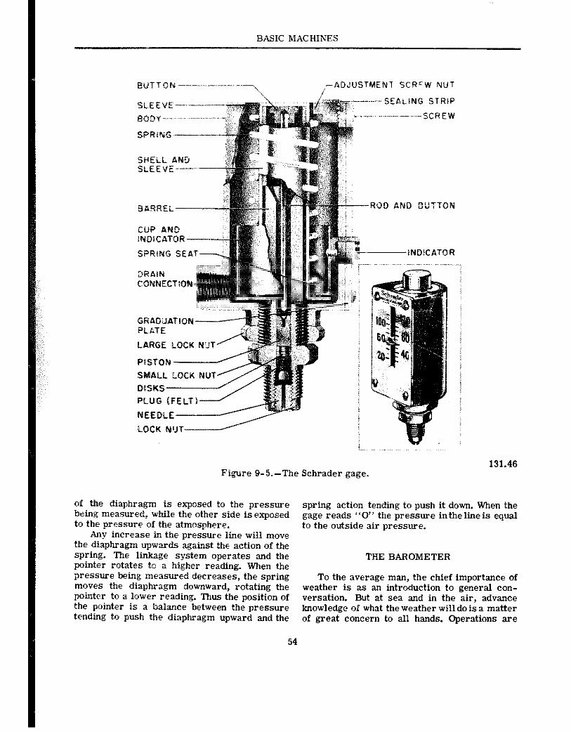
BASIC MACHINES
%wTTON----‘----~ -ADJUSTMENT SCR=W NUT /
NEEL-- I LOCK NUT----‘--
Figure 9-5.-The Schrader gage. 131.46
of the diaphragm is exposed to the pressure being measured, while the other side is exposed to the pressure of the zttmosphere.
Any increase in the pressure line will move the diaphragm upwards against the action of the spring. The lb&age system operates and the pointer rotates to a higher reading. When the pressure being measured decreases, the spring moves the diaphragm downward, rotating the pointer to a lower reading. Thus the position of the pointer is a balance between the pressure tending to push the diaphragm upward and the
54
spring action tending to push it down. When the gage reads “0” the pressure inthelineis equal to the outside air pressure.
THE BAROMETER
To the average man, the chief importance of weather is as an introduction to general con- versation. But at sea and in the air, advance knowledge of what the weather will do is a matter of great concern to all hands. Operations are
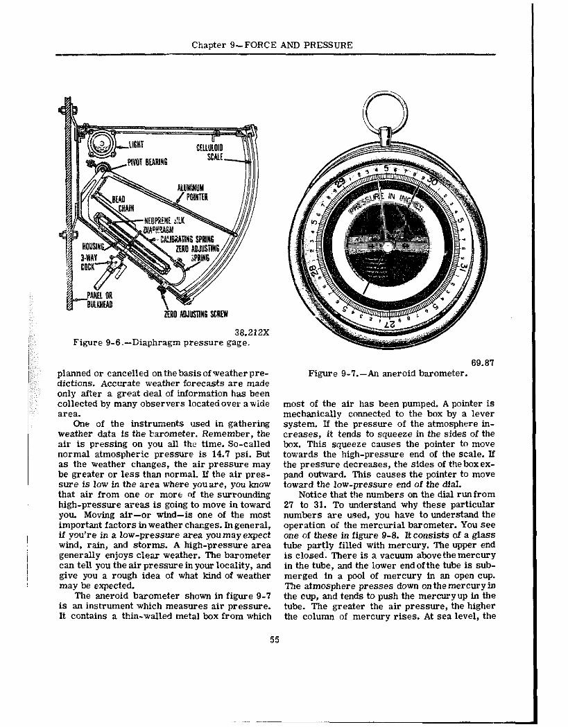
Chapter g--FORCE AND PRESSURE
EN0 AOJOSTIN6 SERtW
38.212X Figure 9-B.-Diaphragm pressure gage.
planned or camelled on the basis of Treather pre- dictions. Accurate weather forecasts are made only after a great deal of information has been collected by many observers locatedover awide area.
One of the instruments used in gathering weather data is the lxrometer. Remember. the air is pressing on you all the time. So&led normal atmospheric pres.mre is 14.7 psi. But as the weather changes, the air pressure may be greater or less than normal. If the air pres- sure is low in the area where you are, you know that air from one or more of the surrounding high-pressure areas is going to move in toward you. Moving air-or wind-is one of the most important factors in weather changes. In general, if you’re in a low-pressure area you may expect wind, rain, and storms. A high-pressure area generally enjoys clear weather. The barometer can tell you the air pressure in your locality, and give you a rough idea of what kind of weather may be expected.
The aneroid barometer shown in figure 9-7 is an instrument which measures air pressure. It contains a thin-walled metal box from which
69.87 Figure g-T.-An aneroid barometer.
most of the air has been pumped. A pointer is mechanically connected to the box by a lever system. If the pressure of the atmosphere in- creases, it tends to squeeze in the sides of the box. This squeeze causes the pointer to move towards the high-pressure end of the scale. If the pressure decreases, the sides of the box ex- pand outward. This causes the pointer to move toward the low-pressure end of the dial.
Notice that the numbers on the dial runfrom 27 to 31. To understand why these particular numbers are used, you have to understand the operation of the mercurial barometer. You see one of these in figure 9-8. It consists of a glass tube partly filled with mercury. The upper end is closed. There is a vacuum above the mercury in the tube, and the lower end of the tube is sub- merged in a pool of mercury in an open cup. l%e atmosphere presses down on the mercury in the cup, and tends to push the mercuryup in the tube. The greater the air pressure, the higher the column of mercury rises. At sea level, the
55
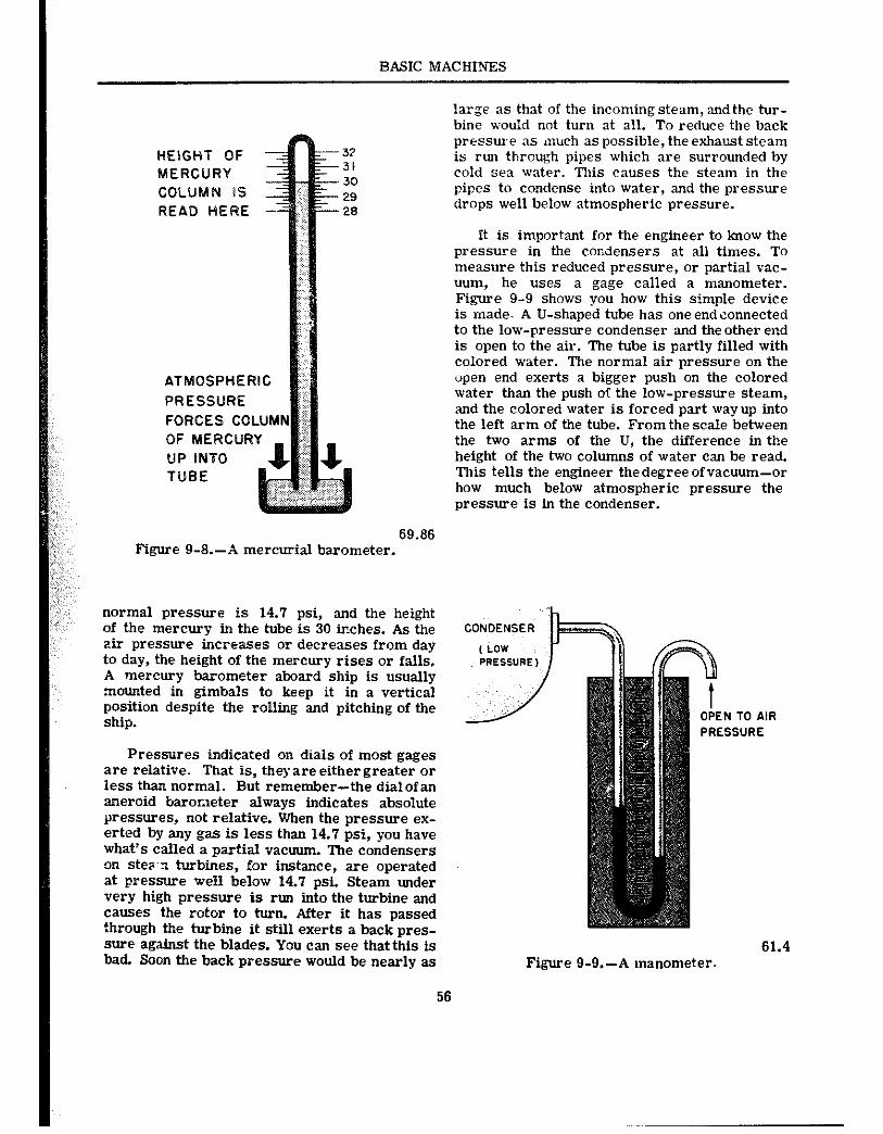
BASIC MACHINES
HEIGHT OF MERCURY COLUMN IS READ HERE
ATMOSPHERlG
PRESSURE
FORCES COLUM
OF MERCURY UP INTO TUBE
large as that of the incoming steam, andthe tur- bine would not turn at all. To reduce the back pressure 3s much as possible, the exhaust steam is run through pipes which are surrounded by cold sea water. This causes the steam in the pipes to condense into water, and the pressure drops well below atmospheric pressure.
It is important for the engineer to know the pressure in the condensers at all times. To measure this reduced pressure, or partial vac- uum, he uses a gage called a manometer. Figure 9-9 shows you how this simple device is made. A U-shaped tube has one end connected to the low-pressure condenser and theother end is open to the air. The tube is partly filled with colored water. The normal air pressure on the upen end exerts a bigger push on the colored water than the push of the low-pressure steam, and the colored water is forced part way up into the left arm of the tube. From the scale between the two arms of the U, the difference in the height of the two columns of water can be read. This tells the engineer thedegree of vacuum-or how much below atmospheric pressure the pressure is in the condenser.
69.86 Figure 9-8.-A inercurial barometer.
nOrma pressure is 14.7 psi, and the height Of the mercury in the tube is 30 inches. As the CONDENSER
zir pressure increases or decreases from day to day, the height of the mercury rises or falls. A mercury barometer aboard ship is usually mounted in gimbals to keep it in a vertical position despite the rolling and pitching of the ship.
Figure 9-9.-A manometer. 61.4
Pressures indicated on dials of most gages are relative. That is, they are either greater or less than normal. But remember-the dial of an aneroid barometer always indicates absolute pressures, not relative. When the pressure ex- erted by any gas is less than 14.7 psi, you have what’s called a partial vacuum. The condensers on step-n turbines, for instance, are operated at pressure well below 14.7 psi. Steam under very high pressure is run into the turbine and causes the rotor to turn. After it has passed through the turbine it still exerts a back pres- sure against the blades. You can see that this is bad. Soon the back pressure would be nearly as
56
Chapter g--FORCE AND PRESSURE
SLIIMARY
Here are seven points that you should remember-
A force is apushor apull exerted on--or by- an object.
Force is generally measured in pounds. Pressure is the force per unit area which is
exerted on, or by, an object. It is com- manly measured in pounds per square inch-psi.
Pressure is calculated by the formula P =f.
Spring scales andlever balances are familiar instruments you use for measuring forces. Bourdon gages, barometers, and manometers art? instruments for the measurement of pressure.
The normal pressure of the air is 14.7 psi at sea level.
Pressure is generally relative. It is some- times greater-sometimes less-than normal air pressure. When pressure is iess than the normal air pressure, you call it vacuum.
57
CHAPTER 10
HYDROSTATIC AND HYDRAULIC MACHINES
RYDROSTA’IC MACHINES
LIQLmS AT REST
P$ u know that liquids exert pressure. In order that your ship may remail float, the wat Jr must push upward on the hull. But the water is ah exerting pressure on the sides. If you: are billeted on a submarine, you are more co-zious of water pressure-when you’re submerged the sub is being squeezed from 211 sides. If you duties include deep-sea diving, you’ll go over the side pumped up like a tire so that you can withstand the terrific force of the water below. The pressure exerted by the sea water, or by any liquid at rest, is called hydrostatic pressure. In handling torpedoes, mines,deptheharges, and some types of aerial bombs, you’ll be dealing with devices which are operated by hydrostatic pressure.
In chapter 9, you found out that all fluids exert pressure in all directions. That’s simple enough. But how great is the pressure? Try a little experiment. Place a pile of blocks in front of you on the table. Stick the tip of your finger under the first block from the top. Not much presstire on your finger, is there? Stick it in between the third and fourth blocks. Tlte pres- sure on your finger has increased. Now slide your finger under the bottom block in the pile. There you find the pressure is greatest. The pressure increases as you go lower in the pile. You might say that pressure increases with depth. The same is true in liquids. The deeper you go, the greater the pressure becomes. But, depth isn’t the whole story.
Suppose the blocks in the preceding para- graph were made of lead. The pressure at any level in the pile would be considerably greater. Or, suppose they were blocks of balsa wood-the
56
pressure at each level wouldn’t be so great. Pressure, then, depends not only on the depth, but also on the weight of the material. Since you are dealing with pressure-force per unit of area-you will also be dealing with weight per unit of volume-or density.
When you talk about the density of a sub- stance you are talking about its weight per cubic foot-or per cubic inch. For example, the density of water is 62.5 lb. per cu. ft. This gives you a more exact way of comparing the weights of two materials. To say that lead is heavier than water isn’t a cbmplete statement. A 22-caliber bullet . ,esn’t weigh as much as a pail of water. It is true, however, that a cubic foot of lead is lots heavier than a cubic foot of water. Lead has a greater density than water. The density of lead is 710 lb. per cu. ft., as compared with 62.5 lb. per cu. ft. for water.
Pressure depends on two factors-depth. and density-so it is easy towrite aformulathat will help you find the pressure at any depth in any liquid. Xere it is-
P =IixD
in which
P =pressure, in lb. per sq. in., or lb. per sq. ft
H = depth of the point, measured in feet or inches.
and
D = density in lb. per cu. in. or in lb. per cu. ft.
Note: If inches are used, they must be used throughout; if feet are used, they must be used throughout.
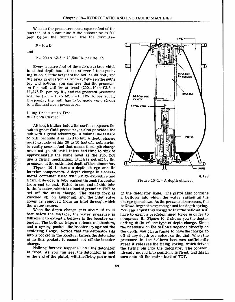
Chapter lo-HYDROSTATIC AND HYDRAULIC MACHINES
what is the pressure on one square foot of the surface of a submarine lf the submarine is 200 feet below the surface? Use the formula-
P’HxD
P- 200 x 62.5 = 12,500 lb. per sq. ft.
Every square foot of the sub’s surface which is at that depth has a force of over 6 tons push- ing in onit. Uthe height ofthe ix11 is 20 feet, and the area in question is midway between the sub’s top a?d bottom, you can see that the pressure on the hull xvi11 be at least (200-10) x 62.5 = 11,875 lb. per sq. ft., and the greatest pressure will be (200 + IO) x 62.5 = 13,125 lb. per sq. ft. Obviously, the hull has to be made very strong to withstand such pressures.
Using Pressure t,o Fire the Depth Cha?ge
Although hiding belowthe surface exposes the silb to great fluid pressure, it also provides the sub with a great advantage. A submarine is hard to kill because it is hard to hit. A depth charge must explode within 30 to 50 feet of a scbmarioe to really score. And that means the depth charge must not go off until it has had time to sink to approximately the same level as the sub. You use a firing mechanism which is set off by the pressure at the estimated depth of the submaribe.
Figure 10-l shows a depth charge and its interior components. A depth charge is asheet- metal container filled with a high explosive and a firing device. A tube passes through its center from end to end. Fitted in one end of this tube is the booster, which i; a load of gram&r TNT to set off the main charge. The safety fork is knocked off on launching, and the inlet valve cover is removed from an inlet through which the water enters.
When the depth charge gets abeti 12 to 15 feet below the surface, the water pressure is sufficient to extend a bellows in the booster ex- tender. The bellows trips a release mechanism, and a spring pushes the booster up against the centering flange. Notice that the detonator fits into a pocket in the booster. Unless the detonator 1s in this pocket, it cannot set off the booster charge.
Nothing further happens until the detonator is fired. As you can see, the detonator is held in the end of the pistol, with the firing pin aimed
DETmuTuz
4.198 Figure 10-1.-A depth charge.
at the detonator base. The pistol also contains a bellows into which the water rushes as the charge goes down. As the prossure increases, the bellows begins to expand against the depth spring. You can adjust this spring so that the bellows will have to exert a predetermined force in order to compress it. Figure 10-2 shows you the depth- setting dials of one type of depth charge. Since the pressure on the bellows depends directly on the depth, you can arrange to have the charge go off at a~?y depth you select on the dial. When the pressure in the bellows becomes sufficiently great it releases the firing spring, whichdrives the firing pin into the detonator. The booster, already moved into position, is fired, and this in turn sets off the entire load of TNT.
59
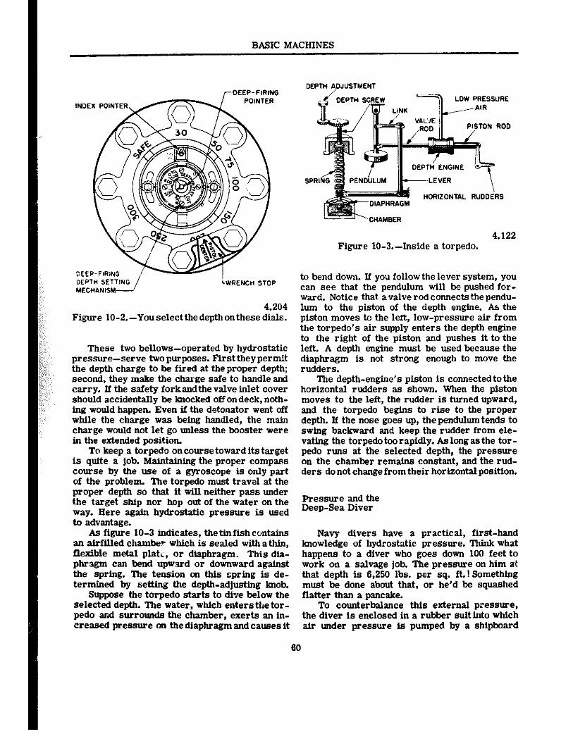
4.204 Figure 10-2.-Yous2lectth2d2pthonth2s2 dials.
These two bellows-operated by hydrostatic pressure-serve twopurposes. Firsttheypermit the depth charge to be fired at theproper depth; second, they make the charge safe to handle and carry. If the safety forkandthe valve inlet cover should accidentally be knocked off on deck, noth- ing would happen. Even ff the detonator went off while the charge was b&g handled, the main charge would not let go unless the booster were in the extended position.
To keep a torpedo on course toward its target is quite a job. Matntainiig the proper compass course by the use of a gyroscope is only part of the problem. The torpedo must travel at the proper depth so that it will neither pass under the target ship nor hop out of the water on the way. Here again hydrostatic pressure is used to advantage.
As figure 10-3 indicates, the tin fish contains an airfilled chamber which is sealed with a thin, flexible metal platL, or diaphragm. This dia- phragm can bend upward or downward against the spring. The tension on thfs spring is de- termined by settfng the depth-adjustfng Imob.
Suppose the torpedo starts to dfve below the selected depth. lbe water, which entersthe tor- pedo and surrounds the chamber, exerts an in- creased pressure on the diaphragm and causes it
BASIC MACBINES
LOW PRESSURE
PISTON ROD
4.122 Figure IO-3.-Inside a torpedo.
to bend down. If you follow the lever system, you can see that the pendulum will be pushed for- ward. Notice that a valve rod connects the pendu- lum to the piston of the depth engine. As the piston moves to the left, low-pressure air from the torpedo’s air supply enters the depth engine to the right of the piston and pushes it to the lett. A depth engine must be used because the diaphragm is not strong enough to move the rudders.
The depth-engine’s piston is connectedtothe horizontal rudders as shown. When the piston moves to the left, the rudder is turned upward, and the torpedo begfns to rise to the proper depth. If the nose goes up, the pendulum tends to swing backward and keep the rudder from ele- vating the torpedo too rapidly. As long as the tor- pedo runs at the selected depth, the pressure on the chamber remains constant, and the rud- ders do not change from their horizontal position.
Pressure and the Deep-Sea Diver
Navy divers have a practical, first-hand knowledge of hydrostatic pressure. Think what happens to a diver who goes down 100 feet to work on a salvage job. The pressure on him at that depth is 6,250 lbs. per sq. ft.! Something must be done about that, or he’d be squashed flatter than a pancake.
To counterbalance this external pressure, the diver is enclosed in a rubber suit into which air under pressure is pumped by a shipboard
80
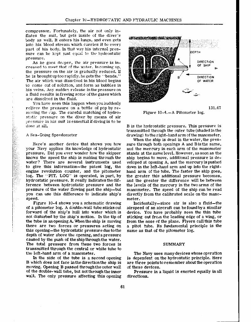
Chapter IO-HYDROK’ATIC AND FYDRAULIC MACHINES
compressor. Fortunately, the air not only in- flates the suit. but gets inside of the diver’s: body as well. It enters his lungs. and even gets into his blood stream which carries it to every part of his body. In that way his internal pres- sm.2 can be kept just equal to the hydrostatic pressure.
As he goes deeper, ihe air pressure is in- creased to meet that of the water. In coming up, the pressure on the air is gradually reduced. If he is brought uptoo rapidly. he gets the “bends.” The air which was j&solved in his blood begins io come out of solution, and form as bubbles in his veins. Any sudden release inthe pressure on a fluid results in freetog some of the gases which ~2 dissolved in the fluid.
You have seen this happen when you suddenly relieve the pressure on a bottle of pop by re- moving the cap. The careful matching of hydro- st:~tic presswe on the diver by l~leans of air prrssure in his suit is essfntial if diving is to be done at all.
:,:,; ‘, .4 Sea-Going Speedometer
Here’s another device that shows you how your Navy applies its knowledge of hydrostatic pressure. Did you 2ver wonder how the skipper
!<Fj:;, knows the speed the ship is making through the water? There are several instruments used to give this information-the patent log, the
,:,,,,, engine revolution counter, and the pitometer log. The “PIT. LOG” is operated, in part, by hydrostatic pressure. It really indicates the dif- ference between hydrostatic pressure and the pressure of the water flowing past the ship-but you can use this difference to indicate ship’s speed.
Fiedre 10-4 shows you a schematic drawing of a pitometer log. A double-waii tube sticks out forward of the ship’s bull into water which is not disturbed by the ship’s motion. In the tip of the tube is an opening A. When the ship is moving there are two forces or pressures acting on this opening-the hydrostatic pressure due to the depth of water above the opening, and apressure caused by the push of the ship through the water. The total pressure from these two forces is transmitted through the central or white tube to the left-hand arm of a manometer.
In the side of the tube is a second opening B which does not face inthe direction the ship is moving. Opening B passed through the outer wall of the double-wall tube, but not through the inner wall. The only pressure affecting this opening
131.47 Figure 10-4.-A Pitometer log.
B is the hydrostatic pressure. This pressure is transmitted through the outer tube (shaded in the drawing) to the right-hand arm of the manometer.
When the ship is dead in the water, the pres- sure through both openings A and Bisthe same, and the mercury in each arm of the manometer stands at the same level. However, as soon as the ship begins to move, additional pressure is de- veloped at opening A, and the mercury is pushed down in the left-hand arm and up into the right- hand arm of the tube. The faster the ship goes, the greater this additional pressure becomes, and the greater the difference will be between the levels of the mercury in the two arms of the manometer. The speed of the ship can be read directly from the calibrated scale on the mano- meter.
Incidentally-since air is also a fluid-the airspeed of an aircraft can be found by a similar device. You have probably seen the thin tube sticking out frc‘n the leading edge of a wing, or from the nose of the plane. Flyers call this tube a pitot tube. Its fundamental principle is the same as that of the pitometer log.
SUMMARY
The Navy uses many derices whose oppration is dependent on the hydrostatic principle. Here are three points to remember aboutthe operation of these devices.
Pressure in a liquid is exerted equally in all directions.
61
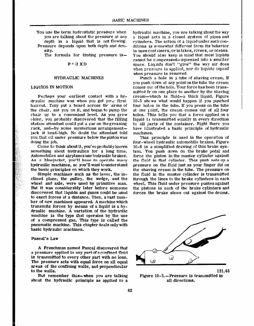
BASIC MACHINES
You use the term hydrostatic pressure when you are talking about the pressure at any depth in a liquid that is not flowing.
Pressure depends upon both depth and den- sity. The formula for finding pressure is-
P=:I XD
HYDRAULIC MACHINES
LIQUIDS IN MOTION
Perhaps your earliest contact with a hy- draulic machine was when you got y0v.z first haircut. Tony put a board across the arms of the chair, sat you on it, and began to pump the chair up to a convenient level. As you grew older, you probably discovered that the filling station attendant could put a car on thegreasing rack, and-by some mysterious arrangement- jack it head-high. No doubt the attendant told you that oil under pressure below the piston was doing the job.
Come to think aboutit, you’veprobablyknown something about hydraulics for a long time. Automobiles and airplanes use hvdraulic brakes. As a bluejacket, you’ll have to operate rn~,y hydraulic machines, st you’ll want to understand the basic principles on which they work
Simple machines such as the lever, the in- clined plaoe, the pulley, the wedge, and the wheel and axle, were used by primitive man. But it was considerably later before someone discovered that liquids and gases could be used to exert forces at a distance. Then, avast num- ber of new machines appeared. A machine which transmits forces by means of a liquid is a hy- draulic machtie. A variation of the hydraulic machine is the type that operates by the use of a compressed gas. This type is called the pneumatic machine. This chapter deals only with basic hydraulic machines.
Pascal’s Law
A Frenchman named Pascal discovered that a pressure applied to any part of aconfined fluid is transmitted to every other part with no loss. The pressure acts with equal force on all equal areas of the confining walls, and perpendicular to the walls.
But remember this-when you are talking about the hydraulic principle as applied to a
hydraulic ma chine, you are talking about the way a liquid act:3 in a closed system of pipes and cylinders. The action of a liquid under such con- ditions is somewhat different from its behavior in opencontainers,orinlakes, rivers, oroceans. You should also keep in mind that most liquids cannot be campressed-squeezed into a smaller space. Liquids don’t “give” the way air does when pressure is applied, nor do liquids expand when pressure is removed.
Punch a hole in a tube of shaving cream. If you. push down at any point on t~he tube the cream comes out of the hole. Your force has been trans- mitted fr,m one place to another by the shaving cream-which is fluid-a thick liquid. Figure 10-5 shcws what would happen if you punched four hol,?s in the tube. If you press on the tube at one Ioint, the cream comes out of all four holes. This tells YOU that a force applied on a liquid i,s transmitted equally in every direction to all 2arts of the container. Right there you have illustrated a basic principle of hydraulic machines.
This principle is used in the operation of four-wheel hydraulic automobile brakes. Figure 10-6 is a simplified drawing of this brake sys- tem. You push down on the brake pedal and force the piston in the master cylinder against the fluid in that cylinder. This push sets up a pressure on the fluid just as your finger did on the shaving cream in the tube. The pressure on the fluid in the master cylinder is transmitted through the lines to the brake cylinders in each wheel. This fluid under pressure pushes against the pistons in each of the brake cylinders and forces the brake shoes out against the drums.
Figure IO-5.-Pressure is transmitted in all directions.
62
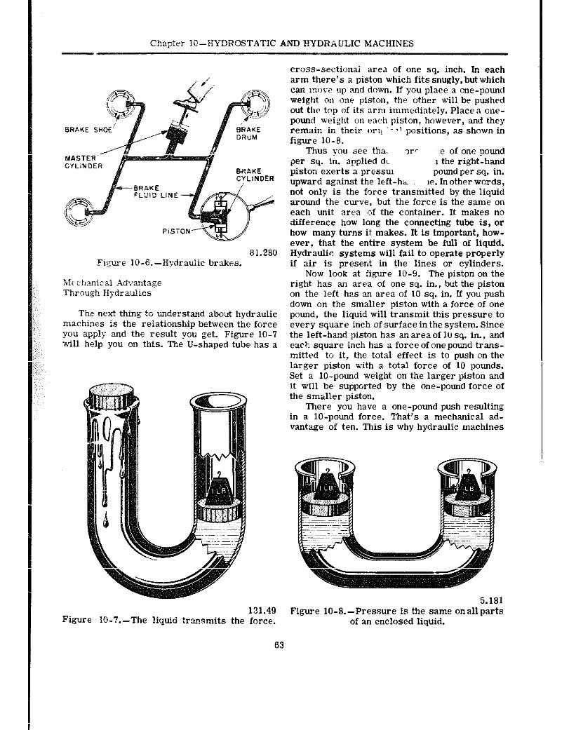
Chzpter IQ-HYDROSTATIC AND HYDRAULIC MACHINES
81.280 Figure IO-6.-Hydraulic brakes.
The next thing to understand about hydraulic machines is the relationship behveen the force you apply and the result you get. Figure 10-7 will help you on this. The U-shaped tube has a
Figure IO-il.-The liquid transmits the force.
cross-sectionai area of one sq. inch. In each arm there’s a piston which fits snugly, but which can more up and down. If you place a one-pound weight on one piston, the other will be pushed out the top of its arm immediately. Place a one- pound weight on each piston, however, and they remain in their ori! .~‘l positions, as shown in figure 10-6.
Thus you see tha. ?r’ ‘e of one pound per sq. in. applied dc ~1 the right-hand piston exerts a pressxn pound per sq. in. upward against the left-h- le. In other words, not only is the force transmitted by the liquid around the curve, but the force is the same on each unit area c,f the container. It makes no difference how long the connecting tube is, or bow may turns it makes. It is important, how- ever, that the entire system be full of liquid. Hydraulic systems will fail to operate properly if air is present in the lines or cylinders.
Now look at figure 10-9. The piston on the right has an area of one sq. in., but the piston on the left has an area of 10 sq. in. If you push down on the smaller piston with a force of one pound, the liquid will transmit this pressure to every square inch of surface in the system. Since the left-hand piston has anareaof 10 sq. in., and eack square inch has a force of one pound trans- mitted to it, the total effect is to push on the larger piston with a total force of 10 pounds. Set a lo-pound weight on the larger piston and it will be supported by the one-pound force of the sm&ller piston.
There you have a one-pound push resulting in a lo-pound force. That’s a mechanical ad- vantage of ten. This is why hydraulic machines
Figure IO-8.-Pressure is the same onallparts of an enclosed liquid.
63
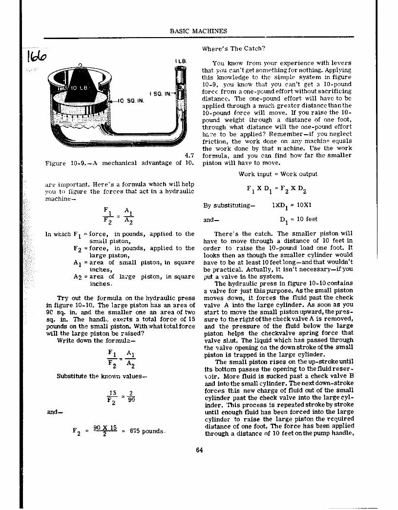
BASIC MACHINES
4.7 ~i-yre 10-9.-A mechmical advantage of 10.
we important. Here’s a formula which will help you to iigure the forces that act in a hydraulic maehine-
YAI F2 A2
In which Fl = force, in pounds, applied to the small piston,
F2 = force, in pounds, applied to the large piston,
Al = area of small piston, in square inches,
A2 = area of large piston, in square inches.
Try out the formula on the hydraulic press in figure 10-10. The large piston has an area of 90 sq. in. and the smaller one an area of two sq. in. The hark& exerts a total force of 15 pounds on the small piston. Withwhattotalforce will the large piston be raised?
Write down the formula-
Ft AI -__- E2 A2
Substitute the known values-
and-
15 -+ F2
F2 = 99 ; I5 = 675 9ounds.
Where’s The Catch?
You know from your experience with levers that you can’t get something for nothing. Applying this knowledge to the simple system in figure 10-9, you know that you can’t get a lo-pound force from a one-pound effort without sacrificing distance. The one-pound effort will have to be applied through a muoh greater distance than the lo-pound force will move. If you raise the IO- pound weight ihrough a distance of one foot, through what distance will the one-pound effort hxx to be applied? Remember-if you neglect friction, the work done on any machine equals the work done by that nachine. L’se the work formula, and you can find how far the smaller piston will have to move.
Work input = Work output
Fl X Dl = F2 X D2
By substituting- 1XDI = 10X1
and- Dl = 10 feet
There’s the catch. The smaller piston will have to move through a distance of 10 feet in order to raise the lo-pound load one foot. It looks then as though the smaller cylinder would have to be at least 10 feet long-andthat wouldn’t be practical. Actually, it isn’t necessary-if you put a valve in the system.
The hydraulic press in figure lo-10 contains a valve for just this purpose. As the small piston moves down, it forces the fluid past the check valve A into the large cylinder. As soon as you start to move the small piston upward, the pr@s- sure to the right of the check valve A is removed, and the pressure of the fluid below the large piston helps the checkvalve spring force that valve shut. The liquid which has passed through the valve opening on the down stroke of the small piston is trapned in the large cylinder.
The small piston rises on the up-stroke until its bottom passes the opening to the fluid r@s@r- wir. More fluid is sucked past a check valve B and into the small cylinder. The next down-stroke forces this new charge of fluid out of the small cylinder past the check valve into the large cyl- inder. ‘this process is repeated stroke by stroke until enough fluid has been forced into the large cylinder to raise the large piston the required distance of one foot. The force has been applied through a distance of 10 feet on the pump handle,
64
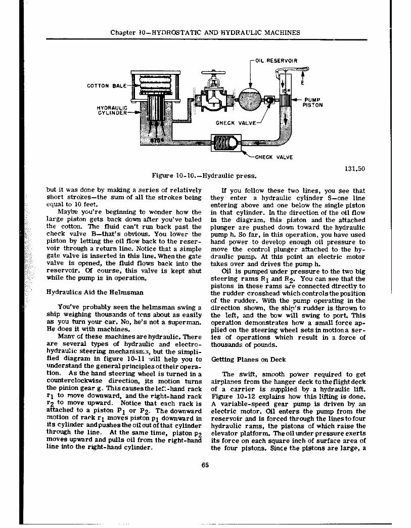
Chaoter IO-HYDROSTATIC AND HYDRAULIC MACHINES
OIL RESERVOIR
COTTON BALE
GHECK VALVE
-=+-CHECK VALVE
Figure lo-lO.-Hydraulic press. i3i.50
but it was done by making a series of relatively short strokes-the sum of all the strokes being equal to 10 feet.
Maybe you’re beginning to wonder how the large piston gets back down after you’ve baled the cotton. The fluid can’t run back past the check valve B-that’s obvious. You lower the piston by letting the oil flow back to the reser- voir through a return line. Notice that a simple gate valve is inserted in this line. Whenthe gate valve is opened, the fluid flows back into the reservoir. Of course, this valve is kept shut while the pump is in operation.
Hydraulics Aid the Helmsman
You’ve probably seen the helmsman swing a ship weighing thousands of tons about as easily as you turn your car. No, he’s not a superman. He does it with machines.
Many cf these machinesare hydraulic. There are several types of hydraulic and electro- hydraulic steering mechanisms, but the simpli- fied diagram in figure lo-11 will help you to understand the general principles of their opera- tion. As the hand steering wheel is turned in a counterclockwise direction, its motion turns the pinion gear g. This causes the l&-hand rack rl to move downward, and the right-hand rack ‘2 to move upward. Notice that each rack is attached to a piston Pl or P2. The downward motion Of rack rl moves piston pl downward in its cylinder and pushes the oil out of that cylinder through the line. At the same time, piston p2 moves upward and pulls oil from the right-hand line into the right-hand cylinder.
If you follow these two lines, you see that they enter a hydraulic cylinder S-one line entering above and one below the single piston in that cylinder. In the direction of the oil flow in the diagram, this piston and the attached plunger are pushed down toward the hydraulic pump h. So far, in this operation, you have used hand power to develop enough oil pressure to move the control plunger attached to the hy- draulic pump. At this point an electric motor takes over and drives the pump h.
Oil is pumped under pressure to the two big steering rams Rl and R2. You can see that the pistons in these rams are connected directly to the rudder crosshead which controls the position of the rudder. With the pump operating in the direction shown, the shi?‘s rudder is thrown to the left, and the bow ~111 swing to port. This operation demonstrates how a small force ap- plied on the steering wheel sets in motion a ser- ies of operations which result in a force of thousands of pounds.
Getting Planes on Deck
The swift, smooth power required to get airplanes from the hanger deck to the flight deck of a carrier is supplied by a hydraulic lift. Figure lo-12 explains how this lifting is done. A variable-speed gear pump is driven by an electric motor. Oil enters the pump from the reservoir and is forced through the lines to four hydraulic rams, the pistons of which raise the elevator platform. The oil under pressure exerts its force on each square inch of surface area of the four pistons. Since the pistons are large, a
65
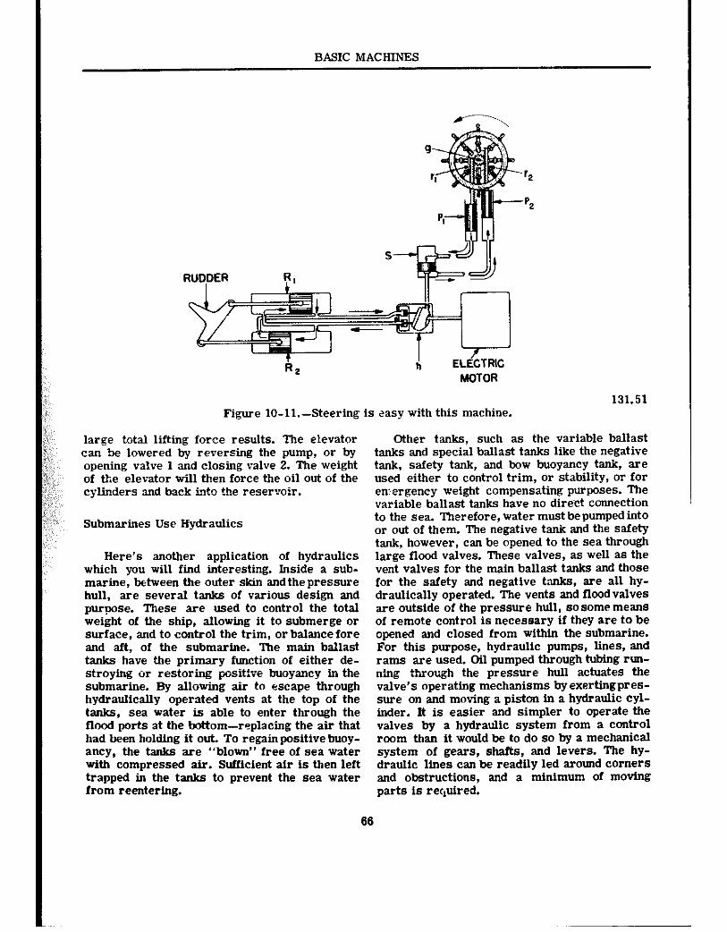
BASIC MACHINES
RUDDER R,
T R2
ELkTRIG MOTOR
131.51 Figure lo-ll.-Steering is easy with this machine.
large total lifting force results. The elevator Other tanks, such as the variable ballast can be lowered by reversing the pump, or by tanks and special ballast tanks like the negative opening valve 1 and closing valve 2. The weight tank, safety tank, and bow buoyancy tank, are of the elevator will then force the oil out of the used either to control trim, or stability, or for cylinders and back intct the reservoir. en:ergency weight compensating purposes. The
variable ballast tanks have no dire.ct CONIeCtiOn
Submarines Use Hydraulics
Here’s another application of hydraulics which you will find interesting. Inside a sub- marine, between the outer skin and the pressure hull, are several tanks of various design and purpose. These are used to control the total weight of the ship, allowing it to submerge or surface, and to control the trim, or balance fore and aft, of the submarine. The main ballast tanks have the primary function of either de- stroying or restoring posit%e buoyancy in the submarine. By allowing air to escape through hydraulically operated vents at the top of the tanks, sea water is able to enter through the flood ports at the bottom-replacing the air that had been holding it out. To regain positive buoy- ancy, the tanks are “blown” free of sea water with compressed air. Sufficient air is then left trapped in the tanks to prevent the sea water from reentering.
to the sea. Therefore, water must be pumped into or out of them. The negative tank and the safety tank, however, can be opened to the sea through large flood valves. These valves, as well as the vent valves for the main ballast tanks and those for the safety and negative tanks, are all hy- draulically operated. The vents and floodvalves are outside of the pressure hull, so some means of remote control is necessary if they are to be opened and closed from withii the submarine. For this purpose, hydraulic pumps, lines, and rams are used. Oil pumped through hrbing run- n’&g tPso”gh the pressure hull actuates the valve’s operating mechanisms byexertingpres- sure on and moving a piston in a hydraulic cyl- inder. It is easier and simpler to operate the valves by a hydraulic system from a control room than it would be to do so by a mechanical system of gears, shafts, and levers. The hy- draulic lines can be readily led around corners and obstructions, and a minimum of moving parts is rec,uired.
66
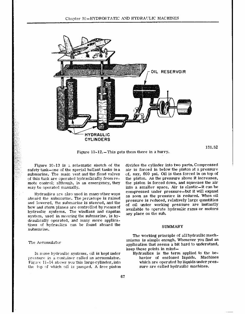
Chnpt.?r lO-HYDROSTATIC Mii HYDRAULIC MACHIEiES
OIL RESERVOIR
CYLINDERS
131.52 Figure IO-l2.-This gets them there in a hurry.
Figure lo-13 is : schematic sketch of tie safety tank-one of the special ballast tanks in a submarine. The main vent and the flood valves of this tank are operated hydraulically from re- mote control; although, in an emergency, they may be operated manually.
Hydraulics are also used in many other ways aboard the submarine. The per&cope is raised and lowered, the su?maarine is steered, and the bow and stern planes are controlled by means of hydraulic systems. ‘Ihe windlass and capstan system, used in mooring the submarine, is hy- draulically operated, and many more applica- tions of hydraulics tax be found aboard the submarine.
The Accumulatr,r
divides the cylinder into two parts. Compressed air is forced in below the piston at a pressure of, say, 600 psi. Oil is then forced in on top of the piston. AS the pressure above it increases, the piston is forced down, and squeezes the air into a smaller space. Air is elastic-it can be compressed under pressure-but it will expand as soon as the pressure is reduced. When oil pressure is reduced, relatively large quantities of oil under working pressure are instantly available to operate hydraulic rams or motors any place on the sub.
SUMMARY
The working principle of all hydraulic mech- anisms is simple enough. Whenever you find an application that seems a bit hard to understand, keep these points in mind-
Hydraulics is the term applied to the be- havior of enclosed liquids. Machines which are operated byliquidsunderpres- sure are called hydraulic machines.
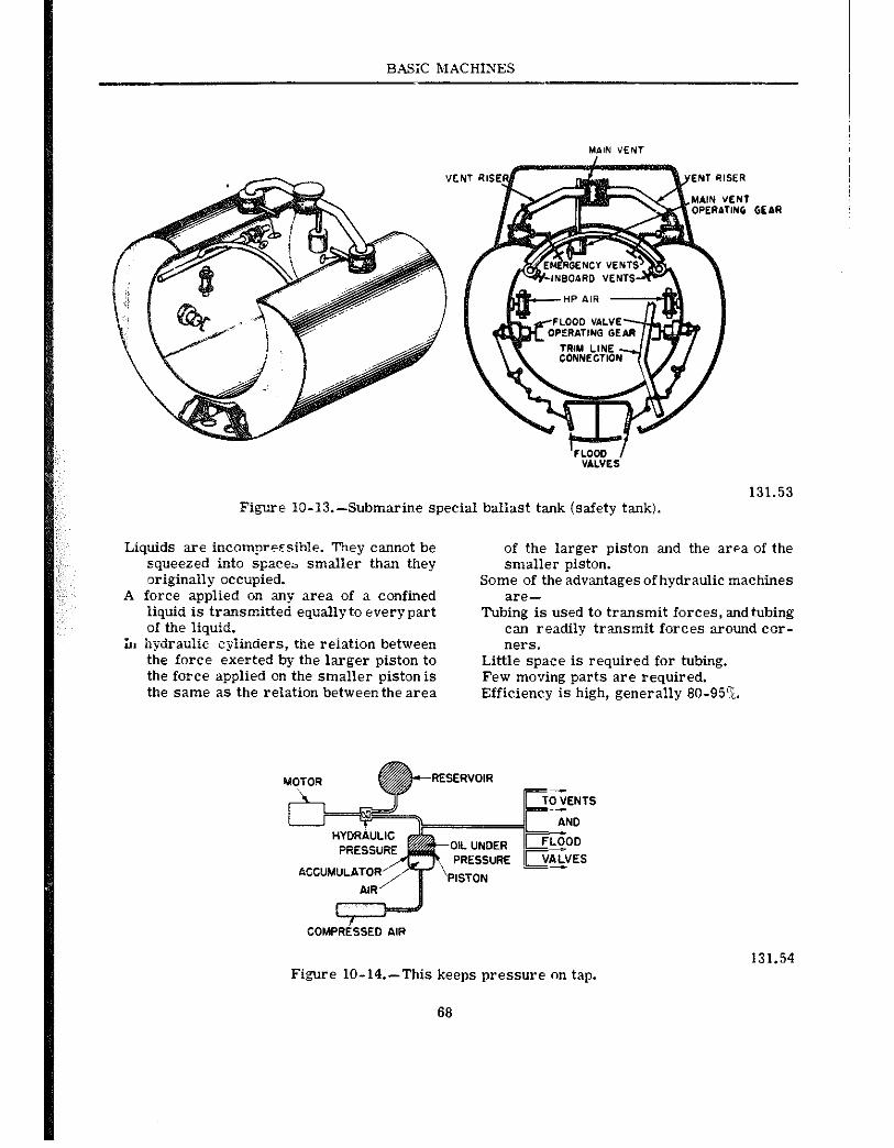
BASX MACHINES
GEAR
Fi,gne IO-13.-Submarin,e special ballast tank (safety tank).
Liquids are incomnrecsible. They cannot be squeezed into space- smaller than they originally occupied.
A force applied on any area of a confined liquid is transmitted equally to every part of the liquid.
in hydraulic cyiinders, the r&&ion between the force exerted by the larger piston to the force applied on the smaller piston is the same as the relation between the area
131.53
of the larger piston and the area of the smaller piston.
Some of the advantages of hydraulic machines are-
Tubing is used to transmit forces, andtubing can readily transmit forces around cor- ners.
Little space is required for tubing. Few moving parts are required. Efficiency is high, generally 80-95%.
I COMPRESSED AIR
131.54 Figure lo-14.-This keeps pressure on tap.
68
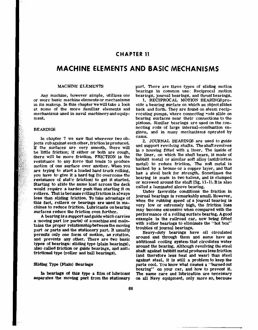
CHAPTER 11
MACHINE ELEMENTS AND BASIC MECHANISMS
MACIIINE ELEMENTS
Any machine, however simple, utilizes one or more basic machine elements or mechanisms in its makeup. In this chapter we will take a look at some of the more familiar elements and mechanisms used in naval machinery and equip- ment,
BEARINGS
ln chapter 7 we saw that wherever two ob- jects rub against each other, friction is produced. If the surfaces are very smooth, there will be little friction; if either or both are rough, there will be more friction. FRICTION is the resistance to any force that tends to produce motion of one surface over another. When you are trying to start a loaded hand truck rolling, you have to- give it a hard tug (to overcome the resistance of static friction) to get it started. Starting to slide the same load across the deck would require a harder push than starting it on rollers. That isbecauserollingfrictionis always less than slidii friction. To take advantage of this fact, rollers or bearings are used in ma- chines to reduce friction. Lubricants onbearing surfaces reduce the friction even further.
A bearing is a support snd guide which carries a motig part (or parts) of a machine and main- tains the proper relationship betweenthe moving p.art or parts and the stationary part. It usually permits only one form of motion, as rotation, and prevents any other. There are two basic types of bearings: sliding type (plain bearings), also called friction or guide bearings, and snti- frictional type (roller and ball bearings).
Sliding Qpe (Plain) Bearings
In bearings of this type a film of lubricant separates the moving part from the stationary
part. There are three types of sliding motion bearings in common use: Reciprocal motion bearings, journal bearings, and thrustbearings.
1. RECIPROCAL MOTION BEARINGSpro- vide a bearing surface on which an object slides back and forth. They are found on steam recip- rocating pumps, where connecting ?ods slide on bearing surfaces near their connections to the pistons. Similar bearings are used on the con- necting rods of large internal-combustion en- gines, and in many mechanisms operated by cams.
2. JOURNAL BEARINGS are used to guide and support revolving shafts. The shaft revolves in a housing fitted with a liner. The inside of the liner, on which the shaft bears, is made of babbitt metal or similar soft alloy (antifriction metal) to reduce friction. The soft metal is backed by a bronze or a copper layer, and that has a steel back for strength. Sometimes the bearing is made in two halves, and is clamped or screwed around the shaftifig. 11-l). Itis also called a laminated sleeve bearing.
Under favorable conditions the friction in journal bearings is remarkably small. However, when the rubbing speed of a journal bearing is very low or extremely high, the friction loss may become excessive when compared with the performance of a rolling surface bearing. Agood example is the railroad car, now being fitted with roller bearings to eliminate the “hot box” troubles of journal bearings.
Heavy-duty bearings have oil circulated around and through them and some have an additional cooling system that circulates water around the bearing. Although revolving thesteel shaft against babbitt metalproduceslessfriction (and therefore less heat and wear) than steel against steel, it is still a problem to keep the parts cool. You know what causes a “burnedout bearing” on your car, and how to prevent it. The same care and lubrication are necessary on all Navy equipment, only more so, because
69
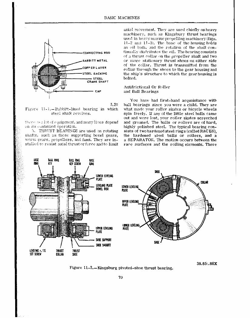
BASIC MACHINES
COWECTING ROD ~iwm1Py distribtlttis the! oil. The be:wing consists of :i thrus( ci:ill:w im the ~m~peller shaft and two
s*eBrTT METAL or nwr~ stationary thrust shoes on either side
COPPER LAYER of the collar. Thrust is transmitted from the collar thraugh thr shoes to the gear housing and
STEEL 8KKIWG the ship’s structure to which the gear housing is STEEL bolted. NK SHAFT
Antifrictional Or Roller CAP and Ball Bearings
You hxve had first-hand acquaintance with 5.20 ball bearings since you were a child. They are
Figat 1 i-I.-Babbitt-lined bearing in which what mnde your rol!er skates or bicycle wheels site-i shaft rero1ris. spin freely. If nny of the little steel balls came
out and were lost, your roller skates screeched t!li;ri: !i ;, Ihl i?t impip:nent. md nrsn:: Iives depend and groaned. The balls or rollers are of hard, cm it.5 vi~intinutd operation. highly polished steel. The typical bearing con-
3. THRUST BEhRITGS 22-e used .3n rotating sists of two hardened steel rings (called RACES), stiti:s. such as ehzt supporting bevel gears, the hardened steel balls or rollers, and a \yflriu gFz-s:‘S. prcpllers, and fans. They are in- a SEPARATOR. The motion occurs between the sta:iid tn rtsist .wiai thrust or fierce and to limit race surfaces and the rolling elements. There
Figwe II-2.-Kingsburg pivoted-shoe thrust bearing.
70
38.85:.88X
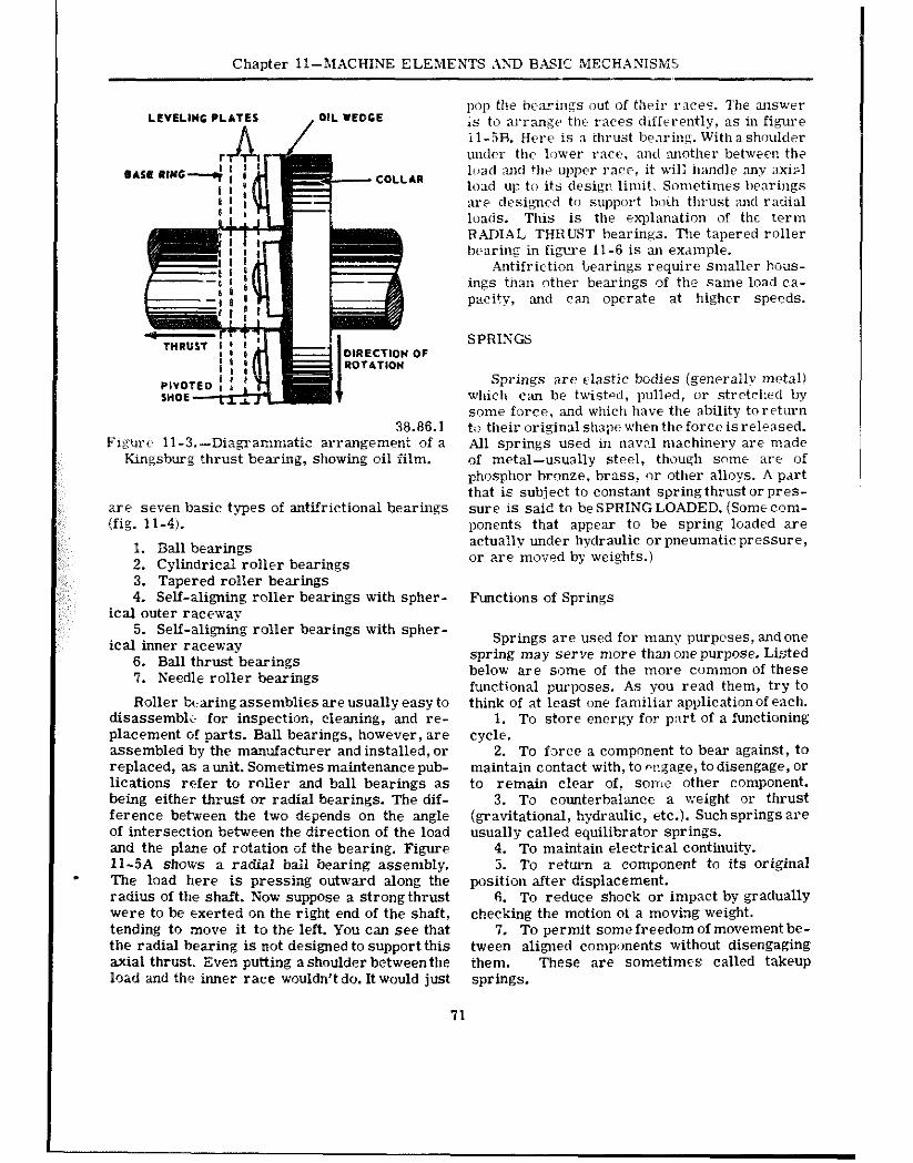
Chapter l?-MACHINE ELEMENTS .QJD B-ASK MECHANISMS
LE”ELl”G PLATES
38.86.1 Figure 11-3.-Diagrammatic arrangement of a
Kingsburg ?hrust bearing, showing oil film.
are seven basic types of antifrictional bearings (fig. 11-4).
1. Ball bearings 2. Cylindrical roller bearings 3. Tapered roller bearings 4. Self-aligning roller bearings with spher-
ical outer race-say 5. Self-a,ligning roller bearings with spher-
ical inner raceway 6. Ball thrust bearings 7. Needle roller bearings
Roller bearing assemblies are usually easy to disassemble for inspection, cleaning, and re- placement of parts. Ball bearings, however, are assembled by the manufacturer and installed, or replaced, as a unit. Sometimes maintenance pub- lications refer to rolier and ball bearings as being either thrust or radial bearings. The dif- ference between the two depends on the angle of intersection between the direction of the load and the plane of rotation of the bearing. Figure 11-5A shows a radial ball bearing assembly. The load here is pressing outward along the radius of the shaft. Now suppose a strong thrust were to be exerted on the right end of the shaft, tending to move it to the left. You can see that the radial bearing is not designed to support this axial thrust. Even putting a shoulder between the load and the inner race wouldn’t do. It would just
71
pop the bearings out of their t’aces. The answer is to arrange the races differently, as in figure il-5R. Here is a thrust bearing. Withashoulder under the lower race, and another between th? load u~d +]I+ upper race, it wili handle nny x&l load up to its design limit,, Sometimes bearings are designed to support boih thrust and radial loads. This is the explanation of the term RADIAL THRUST bearings. T!le tapered roller bearins in figcre 11-6 is an example.
Antifriction bearings require smaller hous- ings thaz: other bearings of the same load ca- pacity, and can operate at higher speeds.
SPRINGS
Springs are dastic bodies (generalI? metal) which can be twisted, pulled, or stretched by some force, and which have the ability toretxrn to their original shape when the force is released. All springs used in nawl machinery are made of metal-usually steel, though some are of phosphor bronze, brass, or other alloys. A part that is subject to constant spring thrust or pres- sure is said to be SPRING LOADED. (Some com- ponents that appear to be spring loaded are actually under hydraulic or pneumatic pressure, or me moved by weights.)
Functions of Springs
Springs are used for many purposes, and one spring may serve more than onepurpose. Listed below are some of the more common of these functional purposes. As you read them, try to think of at least one familiar applicationof each.
1. To store energy for part of a functioning cycle.
2. To fsrce a component to bear against, to maintain contact with, to wgage, to disengage, or to remain clear of, some other component.
3. To counterbalance a weight or thrust (gravitational, hydraulic, etc.). Suchsprings are usually called equilibrator springs.
4. To maintain electrical continuity. 5. To return a component to its original
position after displacement. fi. To reduce shock or impact by gradually
checking the motion of a moving weight. 7. To permit some freedom of movement be-
tween aligned components without disengaging them. These are sometimes &led takeup springs.
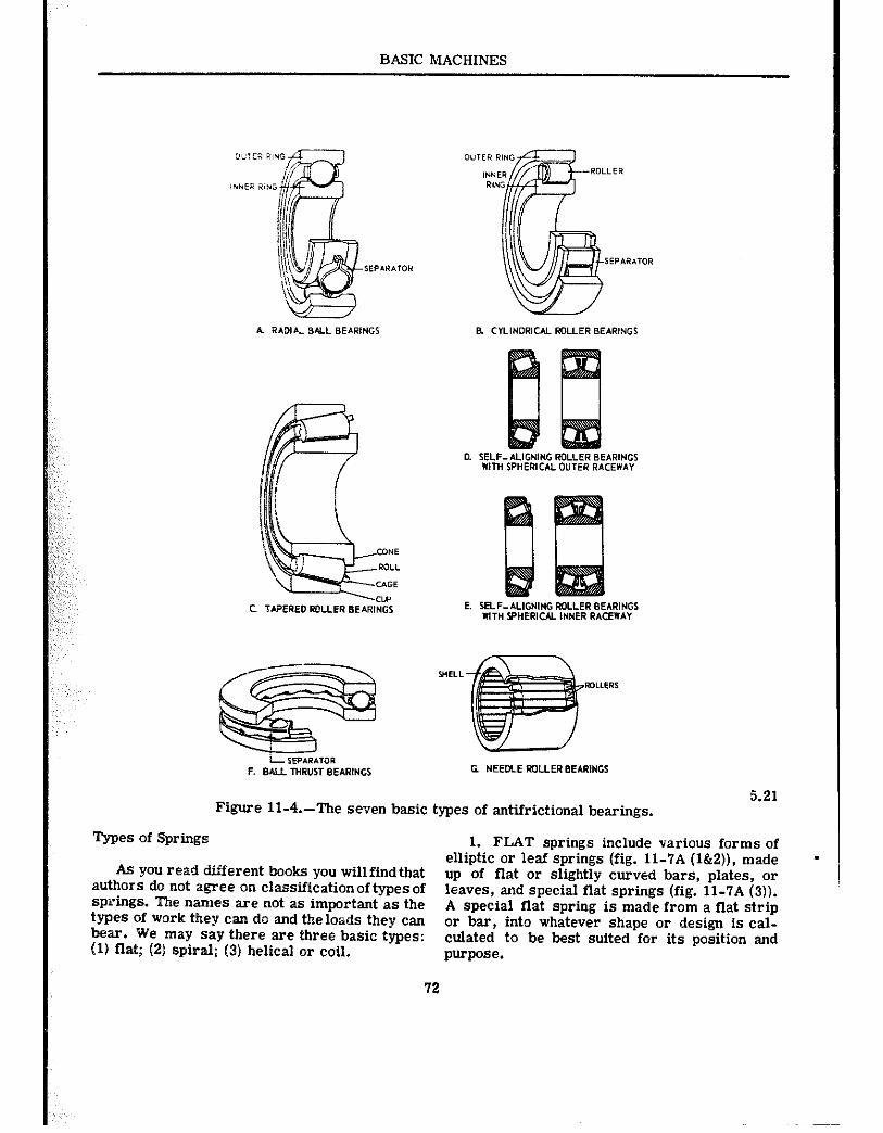
BASIC MACHINES
Figure II-4.-The seven basic types of antifrictional bearings. 5.21
Types of Springs
As you read different books you will find that authors do not agree on classification of types of springs. The names are not as important as the types of work they can do and the loads they can bear. We may say there are three basic types: (11 flat; (21 spiral; (31 helical or coil.
72
1. FLAT springs include various forms of elliptic or leaf springs (fig. 11-7A (l&2)), made up of flat or slightly curved bars, plates, or leaves, and special flat springs (fig. 11-?A (3)). A special flat spring is made from a flat strip or bar, into whatever shape or design is cal- culated to be best suited for its position and purpose.
.
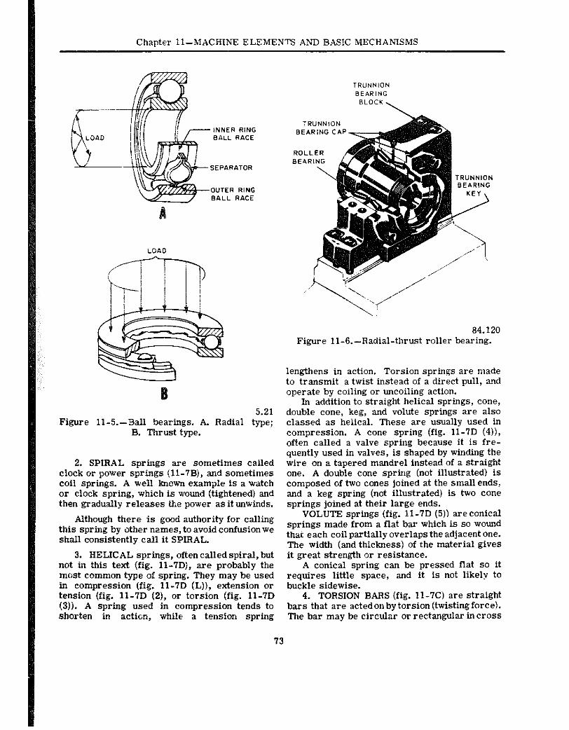
Chaoter ll-MACHINE ELEMENTS AND BASIC MECHANISMS
5.21 Figure ll-5.- Ball bearings. A. Radial type;
B. Thrust type.
2. SPIRAL springs are sometimes called clock or power springs (11-?B), and sometimes coil springs. A well known example is a watch or clock spring, which is wound (tightened) and then gradually releases the power as it unwinds.
Although there is good authority for calling this spring by other names, to avoid confusion we shall consistently call it SPIRAL.
3. HELICAL springs, often called spiral, but not in this text (fig. ll-7Dj, are probably the most common type of spring. They may be used in compression (fig. ll-7D (L)), extension or tension (fig. 11-7D (2j, or torsion (fig. 11-7D (3)). A spring used in compression tends to shorten in action, while a tension spring
84.120 Figure 11-6.-Radial-thrust roller bearing.
lengthens in action. Torsion springs are made to transmit a twist instead of a direct pull, sod operate by coiling or uncoiling action.
In addition to straight helical springs, cone, double cone, keg, and volute springs are also classed as helical. These are usually used in compression. A cone spring (fig. 11-7D (4)), often called a valve spring because it is fre- quently used in valves, is shaped by winding the wire on a tapered mandrel instead of a straight one. A double cone spring (not illustrated) is composed of two cones joined at the small ends, and a keg spring (not illustrated) is two cone springs joined at their large ends.
VOLUTE springs (fig. ll-7D (5)) areconical springs made from a flat bar which is so wound that each coil partially overlaps the adjacent one. The width (and thickness) of the material gives it great strength or resistance.
A conical spring can be pressed flat so it requires little space, and it is not likely to buckle sidewise.
4. TORSION BARS (fig. ll-7C) are straight bars that are acted on by torsion (twisting force). The bar may be circular or rectangular in cross
73
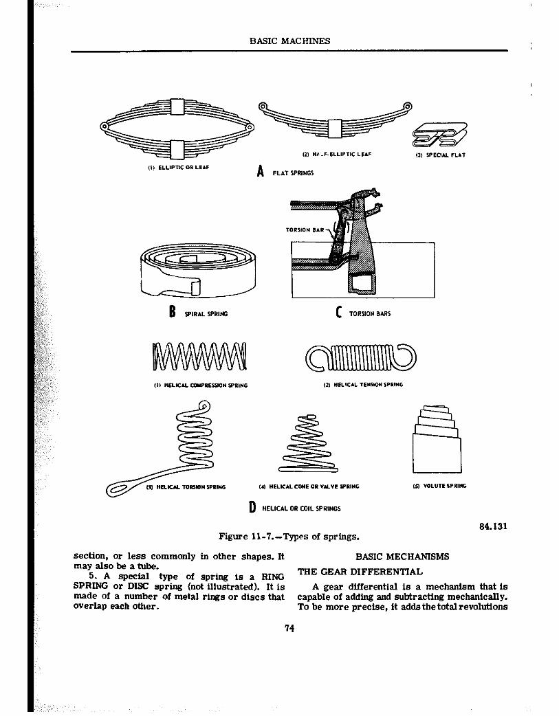
BASIC MACHINES
Figure Il-7.-Types of springs. 84.131
section, or less commonly in other shapes. It may also be a tube.
BASIC MECHANISMS
5. A special type of spring is a RING THE GEAR DIFFERENTIAL
SPRING or DISC spring (not illustrated). It is A gear differential is a mechanism that ts made of a number of metal rings or discs that capable of adding and subtracting mechanically. overlap each other. To be more precise, it adds the total revolutions
14
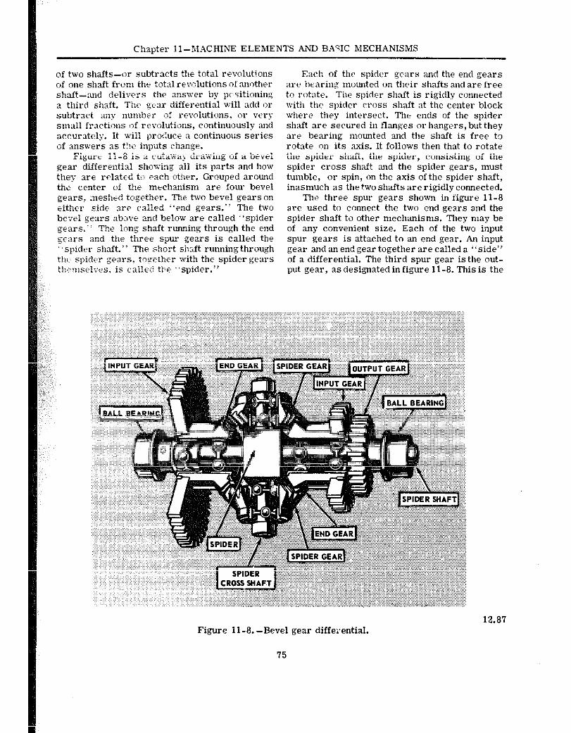
Chapter Il-MACHINE ELEMENTS .&NJ BASIC MECHANISMS
of two shafts-or subtracts the total revolutions of one shaft from the total revolutions of another shaft-and delivers the answer by p’~~sitioning a third shaft. The gear differential will add or subtract any number of revolutions, or very small fractions of revolutions, continuously and accurately. It will proc:uce a continuous series of answers 3s t!?e inputs change.
Figure 11-8 is a cutaway drawing of a bevel gear differential showing all its parts and how they are related to each other. Grouped around thi- writer oi the mechanism are four bevel gears, meshed together. The two bevel gearson either side are called “end gears.” The two bevel gears abt?ve xd below are called “spider geat3.” The long shaft running through the end gears and the three spur gears is called th? “spider shnft.“ The short shaft runningthrough the spider gears, together with the spider gears tl!i~~r~elves, is caller! tie “spider.”
Each of the spider gears and the end gears are hearing mounted on their shafts and are free to rotate. The spider shaft is rigidly connected with the spider cross shaft at the center block where they intersect. The ends of the spider shaft are seclired in flanges or hangers, but they are bearing mounted and the shaft is free t3 rotate on its axis. It follows then that to rotate the spider shaft, the spider, consisting of the spider cross shaft and the spider gears, must tumble, or spin, on the axis of the spider shaft, inasmuch as the two shafts are rigidly connected.
The three spur gears shown in figure 11-8 are used to connect the two end gears and the spider shaft to other mechanisms. They may be of any convenient size. Each of the two input spur gears is attached to an end gear. An input gear and an end gear together are called a “side” of a differential. The third spur gear is the out- put gear, as designated in figure 11-8. This is the
12.87 Figure ll-8.-Bevel gear differential.
75
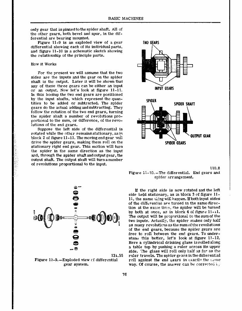
BASIC MACHINES
only gear that is pinned to the spider shaft. .411 of the other gears, both bevel and spur, in the dif- ferential are bearing mounted.
Figure 11-9 is an exploded view of a gear differential showing each of its individual parts, and figure 11-10 is a schematic sketch showing the relationship of the principle parts.
How it Works
For the present we will asslime that the two sides are the inputs and the gear on the spider shaft is the output. Later it will be shown that any of these three gears can be either an input or an output. Now let’s look at figure 11-11. In this hookup the two end gears are positioned by the input shafts, which represent the quan- tities to be added or subtracted. The spider gears do the actual adding and subtracting. They follow the rotation of the two end gears, turning the spider shaft a number of revolutions pro- portional to the sum, or difference, of the revo- lutions of the end gears.
Suppose the left side of the differential is rotated while the other remains stationary, as in block 2 of figure 11-11. Themovingendgear wlil drive the spider gears, making them roll on the stationary right end gear. This motion will turn the spider in the same direction as the input and, through the spider shaft and output gear, the out~~ut shaft. The output shaft will turn anumber of revolutions proportional to the input.
6 8 -.
131.55 Figure ll-9.--Exploded view of differential
gear system.
INPiit GEARS
SPIDER-GEARS
110.8 Figure II-IO.-The differential. End gears and
spider arrangement.
If the right side is now rotated and the left side held stationary, as in block 3 of figure ll- 11, the same r;;ingwil;bappen. Ifbothinput sides of the diiftreniial are turned in the same direc- tion at the SZ:IF tirze, the spider will be turned by both at once, as in block 4 of figure 11-11. The output will be propotiional to the sum of the two inputs. Actxal!y, the spider n?akes only half as many revoIllticns as the sum of the revolutions of the end gears, because the spic!er gears are free to roll between the end gears. To under- stanu this better, let’s look at figure 11-12. Here a cylindrical drinking g:lass io rolled along a table top by pushing a ruler across its upper side. The glass will roll oniy ha1.f as far as the ruler travels. The spider gears’ in thedifferential roll against the end gears in en.actlv the ;.~rne way. Of course, the ap.s’wer can be corwc?ec; i..,
16
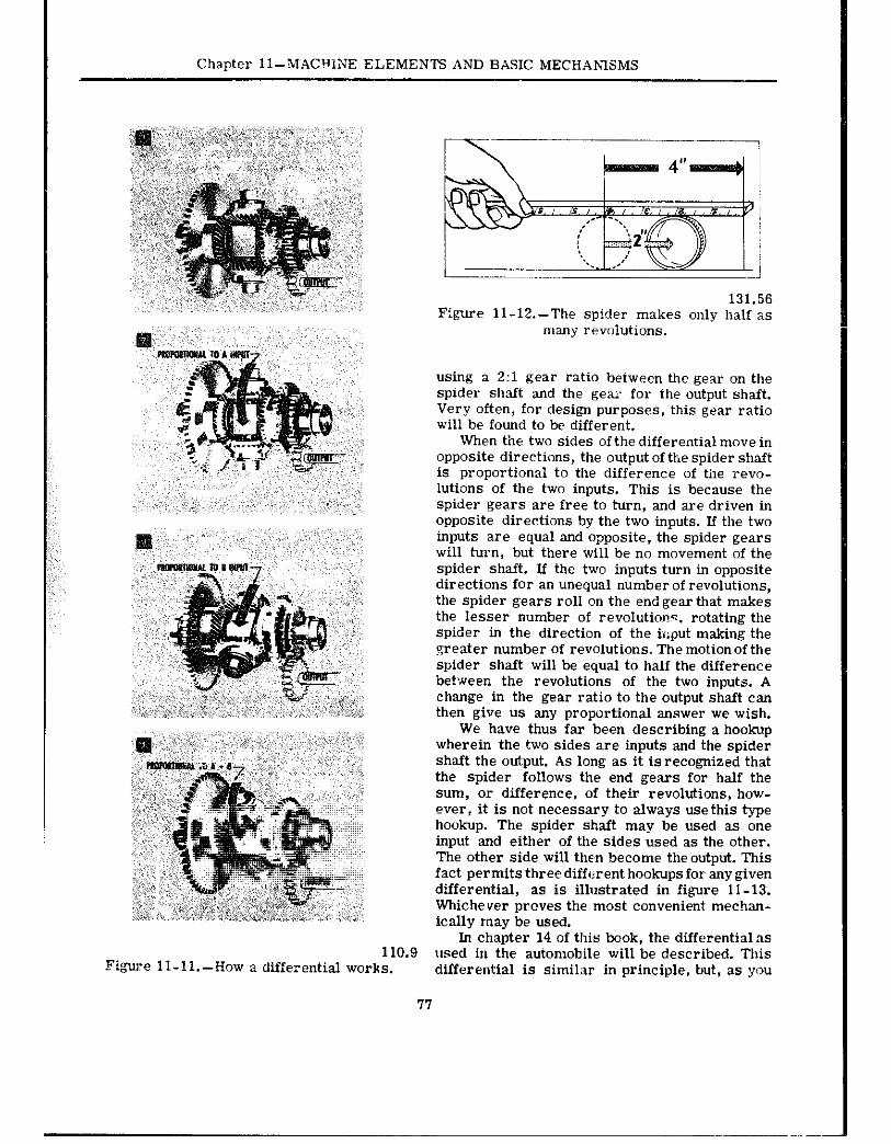
Chapter ll-MACHIXE ELEMENTS AND BASIC MECHANISMS
131.56 Figure 11-12.-The spider makes only half as
many revolutions.
using a 2:l gear ratio between the gear on the spider shaft and the gex for the output shaft. Very often, for design purposes, this gear ratio will be found to be different.
When tie two sides of the differential move in opposite directions, the output ofthe spider shaft is proportional to the difference of the revo- lutions of the two inputs. This is because the spider gears are free to turn, and are driven in opposite directions by the two inputs. If the two inputs are equal and opposite, the spider gears will turn, but there will be no movement of the spider shaft. If the two inputs turn in opposite directions for an unequal number of revolutions, the spider gears roll on the end gear that makes the lesser number of revolution?. rotating the spider in the direction of the hiput making the greater number of revolutions. The motion of the spider shaft will be equal to half the difference between the revolutions of the two inputs. A change in the gear ratio to the output shaft can then give us any proportional answer we wish.
We have thus far been describing a hookup wherein the two sides are inputs and the spider shaft the output. As long as it is recognized that the spider follows the end gears for half the sum, or difference, of their revolutions, how- ever, it is not necessary to always use this type hookup. The spider shaft may be used as one input and either of the sides used as the other. The other side will then become the output. This fact permits three different hookups for any given differential, as is illustrated in figure 11-13. Whichever proves the most convenient mechan- ically may be used.
In chapter 14 of this book, the differential as 110.9 used in the automobile will be described. This
Fi&w:e 11-11 .--How a differential works. differential is similar in principle, but, as you
77
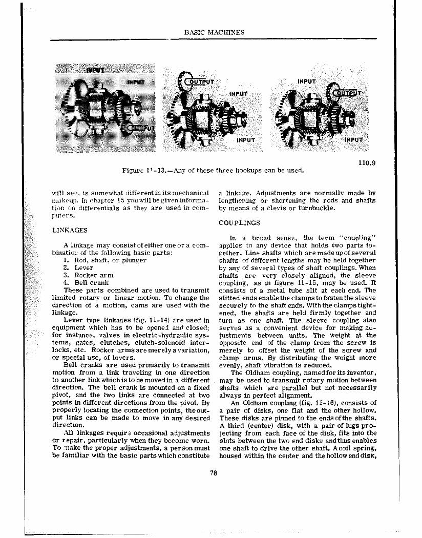
BASIC MACHINES
110.9 Figure 17 -13.-Any of these three hookups can be used.
will see. is somewhat different in its mechanical nx~k~up. In chapter 15 you will be given informa- ti;>n on differentials as they are used in com- puters.
A linkage may consist of either one or a com- binatio:: of the following basic parts:
1. Rod, shaft: or plunger 2. Lever 3. Rocker arm 4. Bell crank These parts combined are used to transmit
limited rotary or linear motion. To change the direction of a motion, cams are used with the linkage.
Lever type linkages (fig. 11-14) ZPE used in equipment which has to be openezi and closed; for instance, valves in electric-hydraulic sys- tems, gates, clutches, clutch-solenoid inter- locks, etc. Rocker arnis are merely a variation, or special use, of levers.
Bell cranJts are used primarily to transmit motion from a link traveling in one direction to another linkxhich is tobe moved in a different direction. The bell crank is mounted on a fixed pivot, and the two links are connected at two points in different directions from the pivot. By Properly locating the connection points, theout- Put links can be made to move in any desired direction.
All linkages require occasional adjustments or repair, particularly when they become worn. To :nake the proper adjustments, a person must be familiar with the basic parts which constitute
a linkage. Adjustments are normally made by len.gthening or shortening the rods and shafts by means of a cl&s or turnbuckle.
COUPLINGS
In a bread sense, the term ‘coupling” applies to any device that holds two parts to- gether. Line shafts which are madeupof several shafts of different lengths may be held together by any of several types of shaft couplings. When shafts are very closely aligned, the sleeve coupling, as in figure 11-15, may be used. It consists of a metal tube slit at each end. The slitted ends enable the clamps to fasten the sleeve securely to the shaft ends. With the clamps tight- ened, the shafts are held firmly together and turn as one shaft. The sleeve coupling also serves as a convenient device for nwking a~- justments between units. The weight at the opposite end of the clamp from the screw is merely to offset the weight of the screw and clamp arms. By distributing the weight more evenly, shaft vibration is reduced.
The Oldham coupling, named for its inventor, may be used to transmit rotary motion between shafts which are parallel but not necessarily always in perfect alignment.
An Oldham coupling (fig. ll-16j, consists of a pair of disks, one flat and the other hollow. These disks are pinned to the ends ofthe shafts. A third (center) disk, with a pair of lugs pro- jecting from each face of the disk, fits into the slots between the two end disks a&thus enables one shaft to drive the other shaft,. Acoil spring, housed within the center and the hollow enddisk,
‘76
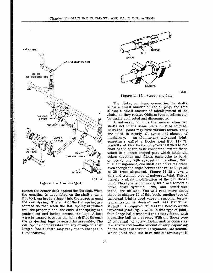
Chaoter ll-MACHINE ELEMENTS Ahii BZSSIC MECHANISMS
79
Figure Il-14.-Linkages.
forces the center disk against the flat disk. When the coupling is assembled on the shaft ends, a flat lock spring is slipped into the space around the coil spring. The ends of the flat spring are formed so that when the f!at spring is pushed into the proper place, the ends ,,f the spring are pushed out and locked around the lugs. A lock: wire is passed between the holes drilled through the projecting lugs to guard the assembly. The coil spring compensates for any change in shaft len@h. (Shaft length may vary ~due to changes in temperature.)
CLkMPS
12.51 Figure 11-15.~Sleeve coupling.
The disks, or rings, connecting the shafts ailow a small amount of radial play, and this allows a small amount of misalignment of the shafts as they rotate. Oldham type couplings can be easily connected and disconnected.
A universal joint is the answer when two shafts net in the same plane must be coupled. Universal joints may have various forms. They are used in nearly all types and classes of machinery. An elementary universal joint, sometims called a Hooke joint (fig. ll-17), consists of tw,o U-shaped yokes fastened to the ends of the shafts to be connected. Within these yokes is a cross-shaped part which holds the yokes together and allows each yoke to bend, or pivot, one with respect to the other. With this arrangement, one shaft can drive the other even though the angle behveen the two is as great as 25” from alignment. Figure 11-18 shows a ring and trunnion type of universal joint. This is merely a slight modification of the old Hooke join:. This type is commonly used inautomobile drive shaft systems. Two, and sometimes three, are utilized. You will read more about these in chapter 14 of this book. Another type of universal joint is used where a smoother torque transmission is desired and less structural strength is required. This is the Bendix-Weiss universal joint (fig. il-19). In this type of joint, four large balls transmit the rotary force, with a smaller ball as a spacer. With the Hooke type of universal joint, a whipping motion occurs as the shafts rotate-the amount of whip depend.ing on the degree 01: shaft misalignment. The Bendix- Weiss joint doIs not have this disadvantage; it
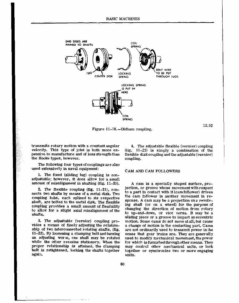
BASIC MACHINES
END DISKS ARE PlNNED TO SHAFTS
LOCKING SPIIING
Figure 11-16.-Oldham coupling.
transmits rotary motion with a constant angular 4. The adjustable flexible (vernier) coupling velocity. This type of joint is both more ex- (fig. 11-23) is simply a combination of the pensive to manufacture and of less strength than flexible diskcoupling and the adjustable (vernier) the Hooke types, however. coupling.
The following four types of couplings are also used extensively in naval equipment: CAM AND CAM FOLLOWERS
1. The fixed (sliding IUP) counlin2 is non- adjustable; however, it-does allo& for a small amount of misalignment in shafting (fig. 11-20).
2. The flexible coupling (fig. ll-21), con- nects hvo shafts bv means of a metal disk. Two coupUng hubs, each splfned to its respective shaft, are bolted to the metal disk. The flexible coupling provides a small amount of flexibility to allow for a slight axial misalignment of the shafts.
3. The adjustable (vernier) coupling pro- vides a means of finely adjusting the relation- ship of two interconnected rotating shafts, (fig. 11-22). Bjj loosening a clamping bolt andturning an adjusting worm, one shaft may be rotated while the other remains stationary. When the proper relationshtp is attained, the cEampfng bolt is retightened, locking the shafts together agail.
A cam is a sueciallv shaued surface. nro- jection, or groove whose mov&nent with respect to a part in contact with it (camfollower) drives the cam follower in another movement in re- sponse. A cam may be a projection ona revolv- ing shaft (or on a wheel) for the purpose of changing the direction of motion from rotary to up-and-down, or vice versa. It may be a sliding piece or a groove to impart aneccentric motion. Some cams do not move at all, but cause a change of motion in the contacting part. Cams are not ordinarily used to transmit power inthe s,ense that gear trams are. They are generally used to modify mechanical movement, thepmver for which is furnished through other means. They may coutrol other mechanical uni.ts, or lock together or synchronize two or more engaging units.
80

Chapter Pl-MACHIhi ELEMENTS AND BASIC MECHANISMS
5.34 Figure 11-I’; .-Universal joint (Hooke type). 81.194
Figure 11-le.-Ringandtrunnionuniversal joint.
Figure ll-19.~-Bendix-Weiss universal jaint.
81
5.34
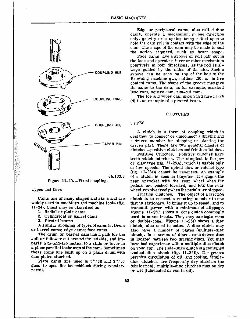
BASIC MACHINES
COUPLING RING
,j------
\e
COUPLING HUE
ss
TAPER PIN
lrl
P
84.133.3 Figure ll-20.-Fixed coupling,
?-,QeS and USeS
Cams are of many shapes and sizes and are widely used in machines and machine tools (fig. 11-24). Cams may be classified as:
1. Radial or plate cams 2. Cylindrical or barrel cams 3. Pivoted beams A similar grouping of types of cams is: Drum
or barrel cams; edge cams; face cams. The drum or barrel cam has a path for the
roll or follower cut around the outside, and im- parts a to-and-fro motion to a slide or lever In a plane parallel to the axls of the cam. Sometimes these cams are built up on a plain drum with cam plates attached.
Plate cams are used In 5”/38 ard 3”/50 guns to open the breechblock during counter- recoil.
Edge or peripheral cams, also called disc cams, operate a mechanism in one direction only, gravity or a spring being relied upon to hold the cam roll in contact with the edge of the cam. The shape of the cam may be made to suit the action required, such as heart shape.
Face cams have a groove or roll path cut in the face xd operate a~ !ever or other mechanism positively in both directions, as the roll is al- ways guided by the sides of the slot. Such a groove can be seen on top of the bolt of the Browning machine gun, caliber .30, or in fire control cams. The shape of the groove may give its name to the cam, as for example, constant lead cam, square cam, run-out cam.
The toe and wiper cam shown infigure 11-24 (d) is an example of a pivoted beam.
CLUTCHES
TYPES
A clutch is a form of coupling which is designed to connect or disconnect a driving and a driven member for stopping or starting the driven part. There are two general classes of clutches-positive clutches andfrictionclutches.
Positive Clutches. Positive clutches have teeth which interlock. The simplest is the jaw or claw type (fig. ll-2SA), which is usable only at low speeds. The spiral claw or ratchet type (fig. 11-25B) cannot be reversed. An example of a clutch is seen in bicycles-it engages the rear sprocket with the rear wheel when the pedals are pushed forward, and lets the rear wheel revolve freely when the pedals are stopped.
Friction Clutches. The object of a friction clutch is to connect a rotating member to one that is stationary, to bring it up tospeed, and to transmit power with a minimum of slippage. Figure 11-25C shows a cone clutch commonly used in motor trucks. They may be single-cone or double-cone. Figure 11-25D shows a disc clutch, also used in autos. A disc clutch may also have a number of plates (multiple-disc clutch). In a series of discs, each driven disc is located between two driving discs. You may have had experience with a multiple-disc clutch on your car. The Hele-Shaw clutch is a combined conical-disc clutch (fig. 11-25E). The groove permits circulation of oil, and ‘cooling. Single- disc clutches are frequenl:l,y dry clutches (no lubrication); multiple-disc c:lutc:hes may be dry or wet (lubricated or run in oil),.
82
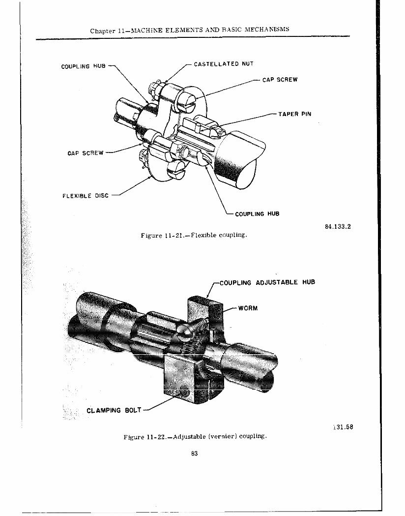
CASTELLATEO NUT
CAP SCREW
FLEXWLE DISC
COUPLING HUB
84.133.2
Figure ll-21.-Flexible coupling.
,-COUPLING ADJUSTABLE HUB
” ,, CLAMPING BOLT -/
i31.58
Figure 11-22.-Adjustable (vernier) COUpli~.
83
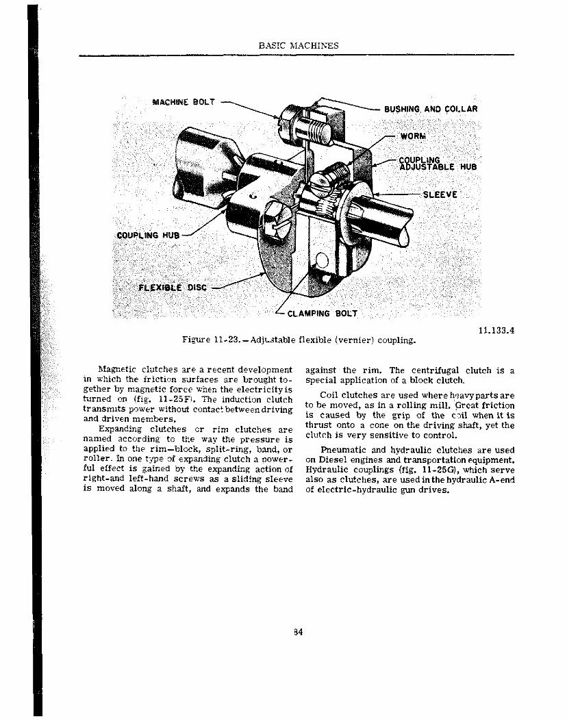
BASIC MACHISES
BUSHING AND COLLAR
11.133.4 Fi+re II-23.-Adj~table flexible (vernier) coupling.
Magnetic cluiches are a recent development in which the iricti,>n surfaces are brought to- gether by magnetic force when the electricity is turned on (fig. IP-25F). The induction clutch transmits power without contact between driving and driven members.
ndinz clutches or rim clutches are name0 accoramg to tne wag tne pressure is applied to the rim-black, split-ring, band, or roller. In one type of expanding clutch a power- ful effect is gained by the expanding action of right-and left-hand screws as a sliding sleeve is moved along a shaft, and expands the band
against the rim. The centrifugal clutch is a special application of a block clutch.
Coil clutches are used where h:?avyparts are to be moved, as in a rolling mill. Great friction is caused by the grip of the tail when it is thrust onto a cone on the driving shaft, yet the clutch is very sensitive to control.
Pneumatic and hydraulic clutches are used on Diesel engines and transportation equipment. Hydraulic couplings (fig. 11-250, which serve also as clutches, are usedinthe hydraulic A-end of electric-hydraulic gun drives.
84
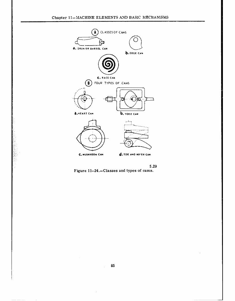
Chanter PI--MACHINE ELEMENTS AND BASIC MECHANISMS
c. FACE CAM
@ FOLiR TYPES OF CAMS
FigUP? 11-24.-Classes and types of cams.
85
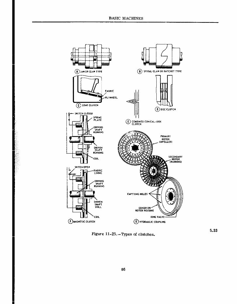
BASIC MACHINES
Figure II-25.-Types of clutches. 5.33
86
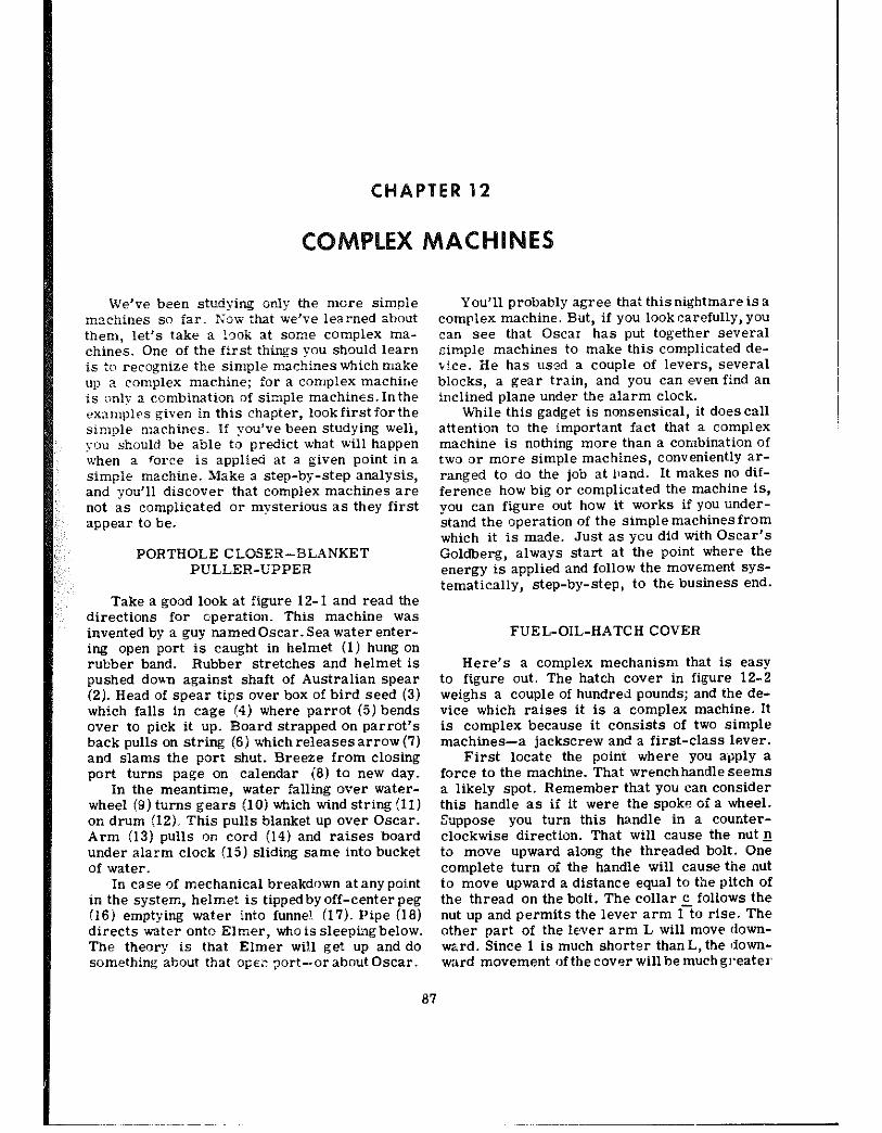
CHAPTER 12
c LEX M s
We’ve been studying only the more simple machines so far. Now that we’ve learned zbout them, let’s take a !ok at some COmpleX ma- chines. One of the first things you should learn is to recognize the simple machines which make up a complex machine; for a complex machir~e is only a combination of simple machines. Inthe @xan~ples given in this chapter, lookfirstforthe simple machines. If you’ve been studying well, you should be able to predict what will happen when a force is applied at a given point in a simple machine. Make a step-by-step analysis, and you’ll discover that complex mathinrs are not as complicated or mysterious as they first appear to be.
PORTHOLE CLOSER-BLANKET PULLER-UPPER
Take a good look at figure 1% 1 and read the directions for operation. This machine was invented by a guy named Oscar. Sea water enter- ing open port is caught in helmet (1) hung on rubber band. Rubber stretches and helmet is pushed doan against shaft of Australian spear (2). Head of spear tips over box of bird seed (3) which falls in cage (4) where parrot (5) bends over to pick it up. Board strapped on parrot’s back pulls on string (6) which releases arrow (7) and slams the port shut. Breeze from closing port turns page on calendar (8) to new day.
In the meantime, water falling over water- wheel (9) turns gears (10) which wind string (11) on drum (IZ)., This pulls blanket up over Oscar. Arm (13) pulls on cord (14) and raises board under alarm clock (15) sliding same into bucket of water.
In case of mechanical breakdown at anypoi~nt in the system, helmet is tippedbyoff-centerpeg (16) emptying water into funne!. (17). Pipe (18) directs water onto Elmer, who is sleepingbelow. The theory is that Elmer wil.1 get up and do something about that OPEZ nort--or about Oscar.
You’ll probably agree that this nightmare is a comp:@x machine. But, if you look carefully, you can see that Oscar has put together several ?.imple machines to make this complicated de- vi.ce. He has used a couple of levers, several blocks, a gear train, and you can even find an inclined plane under the alarm clock.
While this gadget is nonsensical, it does call attention to the important fact that a complex machine is nothing more than a combination of two or more simple machines, conveniently aP- ranged to do the job at hand. It makes no dif- ference how big or complicated the machine is, you can figure out how it works if you under- stand the operation of the simple machines from which it is made. Just as you did with Oscar’S
Goldberg, always start at the point where the energy is applied and follow the movauent SYS- tematically, step-by-step, to the business end.
FUEL-OIL-HATCH COVER
Here’s a complex mechanism that is easy to figure out. The hatch cover in figure 12-2 weighs a couple of hundred pounds; and the de- vice which raises it is a complex machine. It is complex because it consists of two simple machines-a jackscrew and a first-class lever.
First locate the point where you apply a force to the machine. That wr@nchhandle seems a likely spot. Remember that you can consider this handle as if it were the spoke of a wheel. &ppose you turn this handle in a counter- clockwise direction. That will cause the nut 1! to move upward along the threaded bolt. One complete turn of the handle will cause the nut to move upward a distance equal to tbe pitch of the thread on the bolt. The collar 5 follows the nut up and permits the lever arm 1 to rise. The other part of the lwer arm L will move dovm- ward. Since 1 is much shorter than L, the ~down- ward movement of the cover will be much greater
87
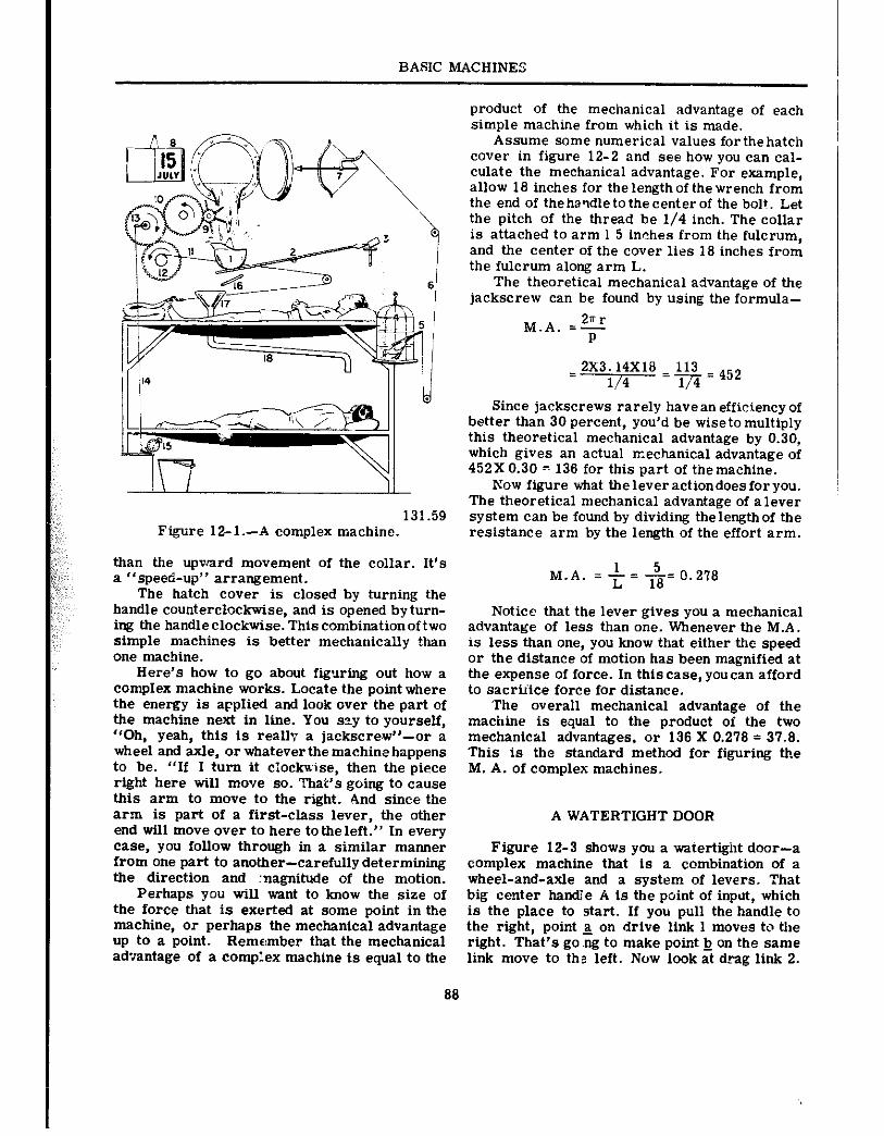
BASIC MACHINES
I I II
131.59 Figure 12-1.-A complex machine.
than the upward movement of the collar. It’s a “speed-up” arrangement.
The hatch cover is closed by turning the handle counterclockwise, and is opened byturn- ing the handleclockwise. This combinationoftwo simple machines is better mechanically than one machine.
Here’s how to go about figuring out how a complex machine works. Locate the point where the energy is applied and look over the part of the machine next in line. You szy to yourself, “Oh, yeah, this is really a jackscrew”-or a wheel and axle, or whatever the machine happens to be. “If I turn it clockwise, then the piece right here will move so. That’s going to cause this arm to move to the right. And since the arm is part of a first-class lever, the other end will move over to here totheleft.” In every ease. you follow through in a similar manner from one part to another-carefully determining the direction and magnitude of the motion.
Perhaps you will want to know the size of the force that is exerted at some point in the machine, or perhaps the mechanical advantage up to a point. Remember that the mechanical advantage of a Complex machine is equal to the
product of the mechanical advantage of each simple machine from which it is made.
Assume some numerical values for the hatch cover in figure 12-2 and see how you can cal- culate the mechanical advantage. For example, allow 18 inches for the length of the wrench from the end of the handle tothe center of the bolt. Let the pitch of the thread be l/4 inch. The collar is attached to arm 1 5 inches from the fulcrum, and the center of the cover lies 18 inches from the fulcrum along arm L.
The theoretical mechanical advantage of the jackscrew can be found by using the formula-
M.A. =$
2X3;;=8 - L$ = 452
Since jackscrews rarely have an efficiency of better than 30 percent, you’d be wiseto multiply this theoretical mechanical advantage by 0.30, which gives an actual mechanical advantage of 452X 0.30 = 136 for this part of themachine.
Now figure what theleveractiondoesforyou. The theoretical mechanical advantage of alever system can be found by dividing thelengthof the resistance arm by the length of the effort arm.
1 5 M.A. = t = x= 0.278
Notice that the lever gives you a mechanical advantage of less than one. Whenever the M.A. is less than one, you know that either the speed or the distance of motion has been magnified at the expense of force. In this case, you can afford to sacriiice force for distance.
‘The overall mechanical advantage of the machine is equal to the product of the two mechanical advantages, or 136 X 0.278 = 37.8. This is the standard method for figuring the M. A. of complex machines.
A WATERTIGHT DOOR
Figure 12-3 shows you a watertight door-a complex machine that is a combination of a wheel-and-axle and a system of levers. That big center handle A is the point of input, which is the place to start. If you pull the handle to the right, point 5 on drive link 1 moves to the right. That’s go .ng to make point h on the same link move to the left. Now look at drag link 2.
88
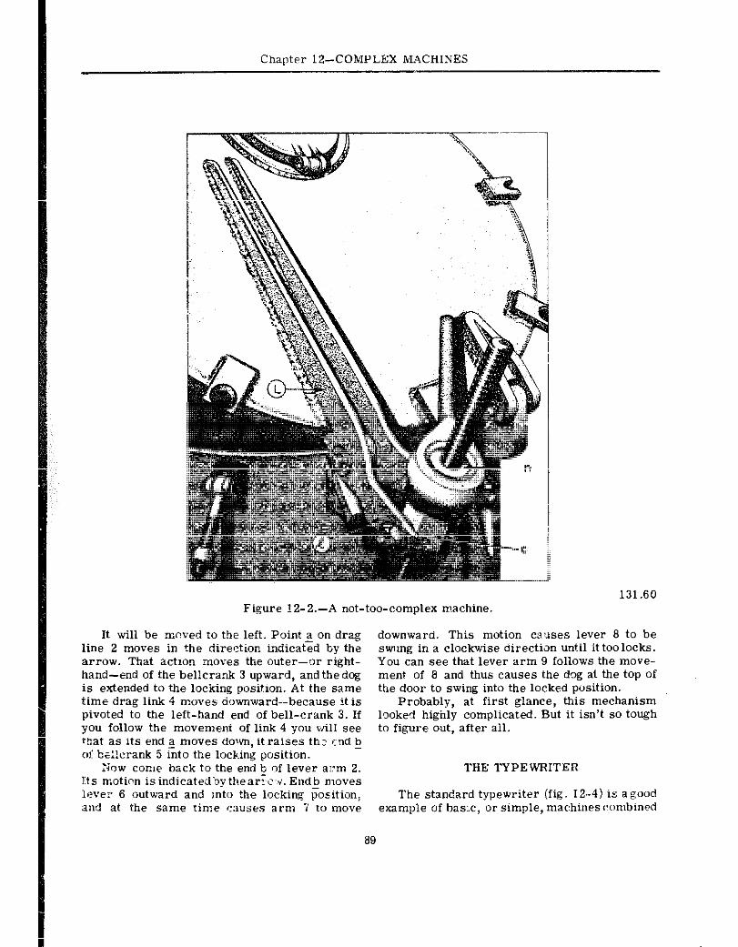
Chapter 1%COMPLEX MACHINES
Figure ?2-2.-A not-too-complex m.achine.
It will be moved to the left. Point 2 on drag line 2 moves in the direction indicated by the arrow. That a&on moves the outer--or right- hand--end of the bellcrank 3 upward, andthedog is extended tn the lociring position. At the same time drag link 4 moves downward-because it is pivoted to the left-hand end of bell-crank 3. If you follow the movement of link 4 you will see that as its end a moves down, it raises thz end b 01: b;:lcrank 5 &to the locking position.
-
:4ow con,e back to the end b of lever a:xn 2. Its moticn is indicated’Dy thea&v. Endb moves I~?ver 6 outward and Into the locking position, and at the same time C:NSW arm 7 to move
a9
131.60
downward. This motion causes lever 8 to be swung in a clockwise directian until it too locks. You can see that lever arm 9 follows the move- ment of 6 and thus causes the dog al the top of the door to swing into the locked position.
Probably, at first glance, this mechanism looked highly complicated. But it isn’t so tough to figure out, after ail.
THE TYPEWRITER
The standard typewriter (fig. 12-4) is agood example of basx, or simple, mac:hines~!ombined
BASIC MACHINES
131.61 Figure 12-X-It works too.
to maR& up a complex machine. In the following text and illustrations, see how many basic machines y:au ran identnfy.
CONSTRUCTiON AND OPERATION
The keyboard of a typewriter contains all the keys, bars, levers, etc., ulxieh are used when operating the maehim.
Each type key operates a type bar with a type head have two cbaraeters (top andbottom). When a key is depressed, the type head is carried up by a system of levers into the type guide where it strikes a ribbon in front of paper on the platen (ro&r) and prints one of the ebaraeters lsdderect on the type head).
The bar at the lower front position of the ~@y~=~ is for spacing me escapement mecha- nism. There is a SHlFT key On each side of the
90
keyboard for shifting the typebarsandsegments up and down, as necessary, in order to use characters in the upper and lower positions on the type heads. Other keys are for backspacing, setting and clearing the tabulator mechanism, margin rekasing, and so forth. There is also a ribbon selector lever, and another lever for changing direction of the ribbon.
A typewriter carriage is positionedonorbe- tween rails, and rides upon some type of roller or ba!l bearings. This carriage includes the platen and all parts of the typewriter which ride with it. The energy which drives the carriage while the machine is being operated comes from a main- spring enclosed in a metal drum. A ratchet wheel and paw1 hold the mainspring in the position desired for a certain amount of tension. A draw band connects the end of the mainspring to the right end of the carriage.
The carriage rack, through the escapement mechanism (explained later), controls the space- by-space movement of the carriage. Theteethof the rack mesh with the escapement wheelpinion. The rack and pinion are conventional spur gear and rack assemblies. The pinion, whenturnedby movement of the carr iage rack, turns the escape- ment wheel. The movement of the escapement wheel is limitedbythe escapement rocker, which moves forward snd backward each time a key or the space bar is depressedand released, moving the carriage on@ space. Thus the escapement rocker allows the carriage tomoveonlyonetype space each time a key or the space bar is struck. Movement of the carriage for each type space is controlled by the escapement wheel held by the LOOSE dog of the escapement rocker. The es- capement wheel may rotateduring regular typing only by the disengagement of the loose dogfrom the escapement wheel. When the escapement wheel shaft turns, it also feeds the ribbon through the ribbon guide.
The platen holds and con!rols thepaper inthe typewriter carriage and s@rv@sasabackstopfor the typeface when it strikesthepaper.Atthe left end of the platen thereisaratchet, which is held in position by a detent (shown later), until it is moved by the carriage return leverontheleft of the carriage. The function of this ratchet is to establish evenly spaced typed llnesonthepaper.
In the middle of the left platen knob in figure 12-4 a variable line spac@r is indicated. This variable line spacer is actually a clutchbetween the ratchet and the plat@n; it holds the platen ratchet in a fixed, locked relation to the platen. By pushing the variable line spacer in with the
w; IE” mc: @AR I”& ICE”
figure 1%4.-External parts of a standard typewriter. 61.36X
BASIC MACHINES
left hand, the operator releases the clutch and can then turn flw F!?EE platen to any desired po- siticx, forward or backward, with either hand. The line finder mechanism on a typewriter re- leases tire ratchet deient and enables theoperator to return the platen to an established writing line withox uslne the variable mechanism.
ESCAPEMENT IXECHAWSM
The escapemer.t mechanism (fig. 12- 5 j is :ne “heart” of a typewriter. It controls movement of the carriage during @ping, allowing it to move a prescribed distance for each actuation of the escapement dogs (illustrated!. The escapement is actuated once every time a type key is de- pressed and &easel, orcanre with each actuation of the space bar.
An escapement consists primarily of a wheel (with teeth on its perimeter) which works in cwjunction with two hoidirg- dogs in a pivoted rocker mechanism. Study the illustration. As the dogs are moved back and iorth, the wheel teeth contact the dogs alternately, resulting in the rotation of the wheel in EQUAL movements or Steps.
The escapemeni rocker rocks forward and backward with respect to the front of the type- writer. This rocker containsthe loose dog (catch) and the rigid (stationary.i dog. As the escape- ment racker pivots on a pivot pin and a pivot screw, it disengages the loose dog from an es- capement wheel tooth and permits the escape- ment wheel to rotaie. ;\s the loose dog moves
off an escapement wheel tooth, the stationary dog moves between the teeth of ttre escapement wheel, limiting the rotation of the escapement wheel to the distance from one tooth to another.
When 2 typewriter is not in use, one tooth of the escapement wheel rests against the LOOSE DOG. Note the position of the loosedogin figure 12-5 (rear viewj. Tension of the carriagemain- spring creates a force on the escapement wheel and overcomes the tension of the loose dog sp-ing and forces the loose dog against a stop. Whq a key is depressed, or the space bar is depressed, :he upper portion of the escapement dog body is rocked to the rear, moving the loose dog out ofthepath of tt,.? wheel tooth. At the same time, the rigid dog is moved into the path of the wheei tooth and the tooth stops against the rigid dog. When the loose dog is disengaged from an escapement wheel tooth, the loose dog spring pulls the loose dog to a position halfwaybetween the next tooth and the one from which it was disengaged.
When the escapement mechanism returns to its normal position, the loose dog engages an escapement wi~eel tooth and is forced back against the loosedog stop by the pull of the main- spring on the carriage. The escapement is then completely restored and ready for the next cycle.
The sequence of mechanical action which takes place during typing is as follows:
1. When a key is struck (depressed) with sufficient force to type, the ribbon rises to COYW the type.
61.39X F&we 12-5.-Escapement mecbatlism.
92
Chapter 12-COMPLEX MACHINES
2. The type prints on the paper and the ribbon is advanced l/2 space by the ribbon feed mechanism.
3. The escapement rocks, allowing the es- capement wheel to advance l/2 space; and the escapement wheel pinion and carriage feed rack allow the carriage to move l/2 space.
4. The escapement returns to its original position, allowing the carriage to move lj2 space and the ribbon to advance l/2 Space.
TYPE BAR MECHAZGGSM
The type bar mechanism carries the type bar up to the platen when a key is depressed. The manner in which this mechanism works is illustrated in figure 12-6. When a type key is depressed, it pivots and depresses a spring be- neath (key lever tension spring). At the same time, it pulls the bell crank forward and causee it to pivot on the fulcrum wire which passes through its base. A wire link between the bell crank and the type bar then pulls tilebase of the type bar forward, causing it to pivot on the ful- crum wire and move the type bar into the type guide (fig. 12-6:. When the type bar goes into
,:, t5e type guide, the bar pushes the universal bar back, causing the bunter rod to trip the escape- ment dogs and allow the carriage to move one space. The segment stop ring (fig. 12-6), called the WHIP, prevents the type bar from springing, thus ensuring clear printing on the paper. When the k$y is released, the key lever tension spring (plus the weight of the type bar) forces the key lever up, returning the type bar action mech- anism to its REST position.
While the type bar action mechanism is operating. the key lever and the ribbonuniversal bar also actuate the ribbon lift mechanism.
RIBBON DRIVE MECHANISM
The function of the ribbon drive mechanism is to move the ribbon from one spool to another in definite increments each time a key or the space bar is depressed, and to raise the ribbon to the line of type. Refer to figure 12-7 as you study how the ribbon drive mechanism works.
when the typewriter carriage moves cme space to the left, the escapement wheel (fig. 12-7) rotates the distance of one tooth.A small gear on the escapement wheel shaft meshes with a slnall gear on the ribbon feed shaft, causing
a sprocket and chain on the other end of the shaft to rotate. The chain which passes over this sprocket drives another sprocket wheel on the right end of theribbondrive shaft (fig. 12-7). Two idler pulleys guide the drive chain and main- tain proper tension on it.
When the drive chain turns the large sprocket wheel on the ribbon drive shaft, a smallgear on the drive shaft meshes with a ribbon spool shaft gear (right or left) and drives the ribbon spool shaft. Vhen the ribbon spool shaft revolvee, it turns a ribbon spool on top and winds the ribbon in small increments onto it. If the ribbon drive shaft is shifted to the right, automatically or manually, the right drive shaft gear meshes with the right ribbon spool shaft gear and revolves the ribbon spool shaft. When the ribbon drive shaft is shifted to the left, the gear on itsleft end drives the left ribbon spool shaft and winds the ribbon to the left.
Ribbon Drive Shaft Detent
You can change the direction of a typewriter ribbon by shifting a reverse lever (fig. 12-7) to the right or left. A slot in the lever limits the amount of space the lever may be moved, and a small spririq retains it in theposition to which it is moved. The rewarm of the reverse lever fits in a notch in the collar on the left end of the ribbon drive shaft, and movee the shaft to the right or left when the ribbon reverse lever is moved.
Ribbon Reverse Mechanism
The funetionoftheribbon reversemechanism is to reverse the ribbon automatically from a full ribbon spool to the empty ribbonspool. The action of this mechanism ensures utilization of the ink in the full length of the ribbon and the came degree of brightness of color in every line of type. The ribbon reverse mechanism is il- lustrated in figure 12-7.
Note the ribbon spool, ribbon reverse trigger, ribbon reveree plunger, and the reversing cam on the ribbon drive shaft.
The end of the ribbon is attached tothe ribbon spool by a catch. As long as there is one com- plete turn of ribbon on the ribbon spool, the ribbon reveree trigger is held in the IN position and the trigger holds up the plunger inside the ribbon spool shaft, so that the lower end of the plunger does not come into contact with the
93
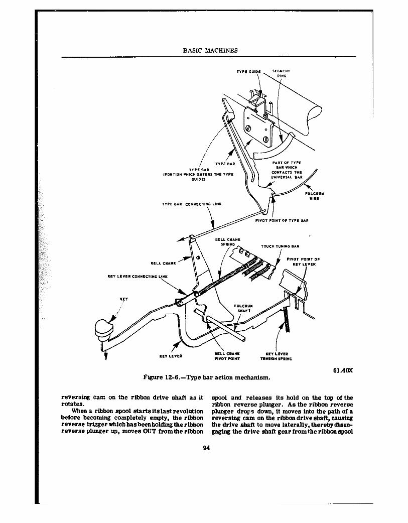
BASIC MACHINES
61.40x Figure 12~&--Type bar action mechanism.
reversing Cam on the ribbon drive shaft as it spool and releases its hold on the top of the rotates. ribbon reverse plunger. As the ribbon revewe
When a ribbon spool starts its last revolution before becoming completely empty, the ribbon
plunger drops down, it moves Into the path of a reversing cam on the ribbon drive shaft. cawing
reverse trtgger ~icbhasbeenholdtngtheribbon the drive shaft to move laterally,Ulerebydlsen- reverse plunger up, moves OUT from the rlbbon gaging the drive shaft gear from the ribbon spool
94
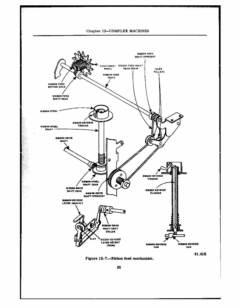
Chapter 1%COMPLEX MACHINES
Figure 12-‘7.-Rtiibon feed mechanism.
95
BASIC MACHINES
shaft gear at one end and eugaging the drive shaft gear and opposite spool shaft gear at the other end.
AS the ribbon starts to wind onto the empty ribbon spool, it pushes the ribbon reverse trigger in, causing the other end of the trigger to en- gage the slot in the top of the ribbon reverse plunger and raise it above the reversing cam on the ribbon drive shaft.
Ribbon Lift Mechanism
The ribbon lift mechanism lifts the ribbonto a position in atiieh it may be struck by the type when its presence is required. and tolet it down when not required (to allow reading of a line that is being typed). Study illustration 12-S as you follow the description of the operation of this mechanism.
When a type key is depressed, the key lever contacts a prong, immediately beneath, which is connected to the ribbon universal bar (U-bar), causing the U-bar to pivot its top forward. As the U-bar top pivots forward it raises the ribbon guide actuating lever liak between theU-bar and the ribbon guide actuatb’~ lever. The ribbon guide actuating lever is ccnnected to the ribbon guide (carrier) and raises it when the key is depressed, bringing the ribbon up in position to be struck by the type head. A spring provides tension to restore the ribbon guide actuating lever.
Note that the ribbon guide actxattng lever has a horizontal slot intbe middle, and the horizontal slot has anindentationinitsupper surface. Then note the ribbon guide actuating lever link shift lever connected to the leff end of the ribbon- shit? shaft. On the right end of the ,?ibbon shift shaft is the ribbon shift detenttc which the ribbon bichrome shift lever is connected.
When the ribbon bichrome shift laver is in the BLACK position, the ribbon guide +tuating lever lb& shift lever movee to position :he ribbon g”ide aetuatt”g lever link at the front end (black position) of the horizontal slo: in the ribbon guide actuating lever. Now, when a key is depressed, the ribbon guide actuating lever 1110pes the ribbon guide in position for the type head to strike the upper (black) portion of the ribbon. If the ribbon bichrome shift lever is moved to the WHITE position (stencil), the ribbon guide actuating lever link shift lever movee the ribbon guide actuating Iever link to the center Of the horizontal slot in the ribbon guide actuating lever. When type keysaredepressed, theribbon
guide actuating lever link moves up ad d>wn in the vertical slot of the ribbon guide actuating lever without moving it, enabling the typist to print characters directly on thr stencil bc II se there is no ribbon in front of the type he a If the ribbon bichrome shift lever is movei ‘o the RED position, the ribbon guide actuating lever link shiit lrver movee tte ribbon guide actuating lever link to the rear end of the slot in the ribbon guide actuating lever. ‘If typing is done with the ribbon guide actuating lever link in this position, the ribbon guide acttiatinglever carries the ribbon guide high enoukh for the type heads to strike the lower (red) portion of the ribbon.
Havmg three positions for setting the ribbon lift mechanism permits efficient use of a stand- ard two-color typewriter ribbon and allows the typist to cut a stencil by merely moving the ribbon bichrome shift lever to the WHITS posi- tion.
BACKSPACE MECHANISM
The function 3f the backspace mechanism is to enable a typist to move the carriage one or more spaces to the right whenever necessary. This mechanism is shown in figure 12-9. When the backspace key lever is depressed, theback- space key lever link causes the bell crank to pivot and transfer the PULL to a horizontal plane. The backspace elide is then moved to the left at the two guide slots shown in the illustra- tion. This action cawee a backspacing paw1 to engage a tooth on the escapement wheel pinion and turn the pinion clockwise until the pinion paw1 O” the escapement wheel IIIOV~S over one tooth 0” the pinion. Since the carriage rack is engaged with the escapement wheel pinion, the carriage is also moved back one space to the RIGHT.
TABULATOR MECHANISM
The tabulator mechanism of a typewriter enables the typist to movethe carriage a definite, predetermined distance by depressing the tabu- lator bar (fig. 12-10). Refer to this illustration frequently as you study the manner in which the tabulator mechanism works.
If the tabulator stops are set as shown at left-center in figure 12-10 and the tabulator bar is depressed, the tabulatorbarframeraises the key set tabulator (KST) stop blade and an arm on the KST stop blade contacts and raises
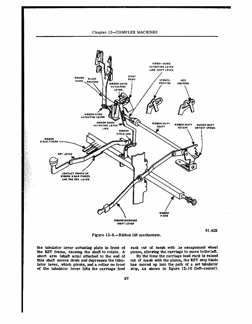
Chapter 1%COMPLEX MACHINES
Figwe 12-B.-Ribbon ltft mechanism. 61.42X
the tabulator lever actuattng plate in front of rack out of mesh with le escapement wheel the XST frame, causing tbe shaft to rotate. A pinion, allowing the carriage to move totheleft. short arm &aft arts) attached to the end of By the time the carriage feed rack is raised this &b&Y moves down and depresses the tabu- out of mesh with the pinion, the KST stop blade lator lever, wbicb pivots, and a roller on front has moved up into the path of a set tabulator of the tabuIator lever lifts the carriage feed stop, as shown in figure 12-10 (left-center).
97
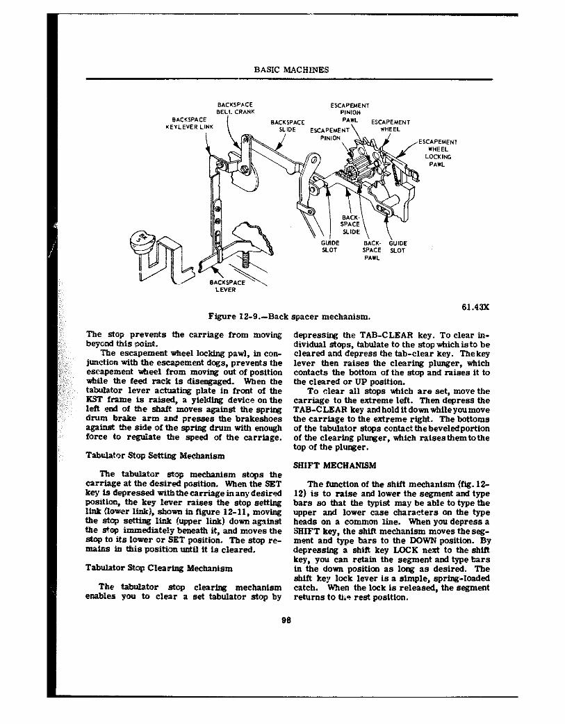
BASIC MACHINES
Figure 12-9.-Back spacer mechanism.
The stop prevents the carriage from movtng beyond this point.
The escapement wheel locking pawl, in con- junction with the escapement dogs, prevents the escapement *eel frwa moving out of position while the feed rack is disengaged. When the tabulator lever actuating plate in front of the KST frame is raised, a yielding device on the left end of the shaft moves against the spring drum brake arm and presses the brakeshoes against the side of the spring drum with enough
te the speed of the carriage.
MechmlSrn
tar stop mechanism stops the desired position. When the SET
key is depressed wttb the carrtage in any desired position, the key lever raises the stop setting 1Ink (lower lb&). &am in figure 12-11, moving the stop setting Iink (upper link) down against the stop immediately beneath it, and moves the st~q to its lower or SET position. The stop re- nrains in this positi~ until it is cleared.
Tabulator Stop Clearing Mechanism
The tor stop clearing mechanism enables you to clear a set tabulator stop by
depressing the TAB-CLEAR key. To clear in- dividual stops, tabulate to the stop which is to be cleared and depress the tab-clear key. The key lever then raises the clearing plunger, which contacts the bottom of the stop and raises it to the cleared or UP position.
To alear all stops which are set, move the carriage to the extreme left. Then depress the TAB-C LEAR key and hold it down while you move the carriage to the extreme right. The bottoms of the tabulator stops contact thebeveledportion of the clearing plunger, which raisesthem tothe top of the plunger.
SHIFT MECHANISM
The functton of the shtft mechanism (fig. 12- 12) is to raise and lower the segment and type bars so that the typist may be able to type the upper and lower ease characters on the type heads on a common line. When you depress a %IFT key, the shift mechanism moves the seg- mmt and type bars to the DOWN position. By depressing a shift key LQCK next to the shift key, you can retain the segment and type bars in the down position as long as desired. The shift key lock lever is a simple, spring-loaded catch. when the lock is released, the segment returns to tkia rest position.
96
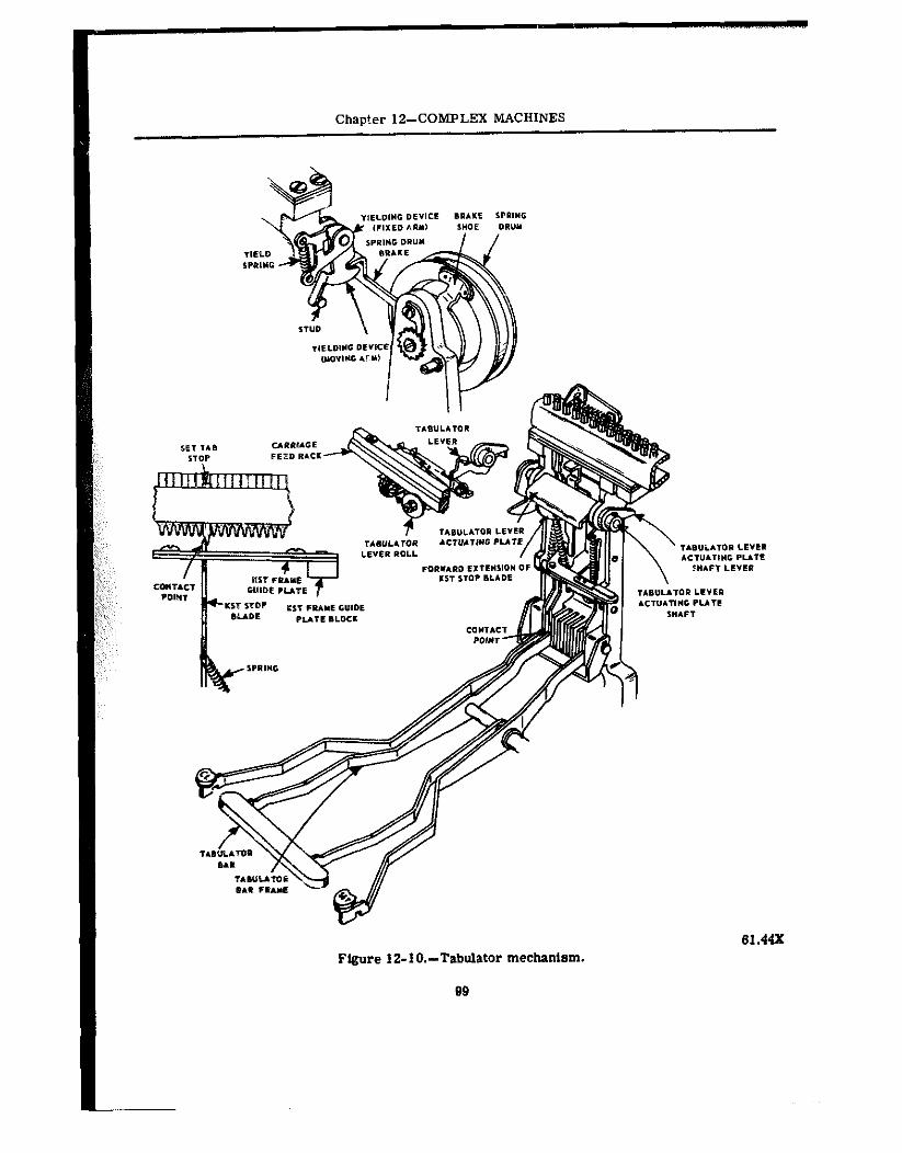
Chapter 12-COMPLEX MACHINES
Figure 12-lO.-Tabulator mechanism. 61.44X
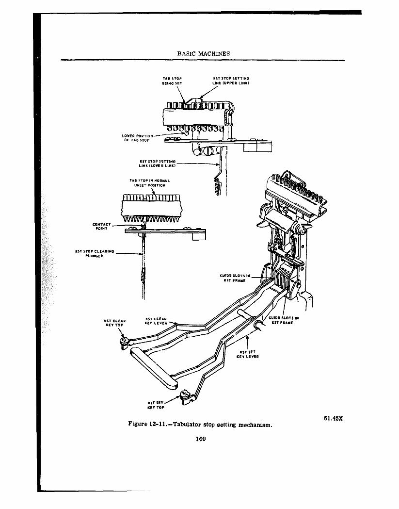
BASIC MACHINES
Figure 12-ll.-Tabulator stop setting mechanism. 61.45X
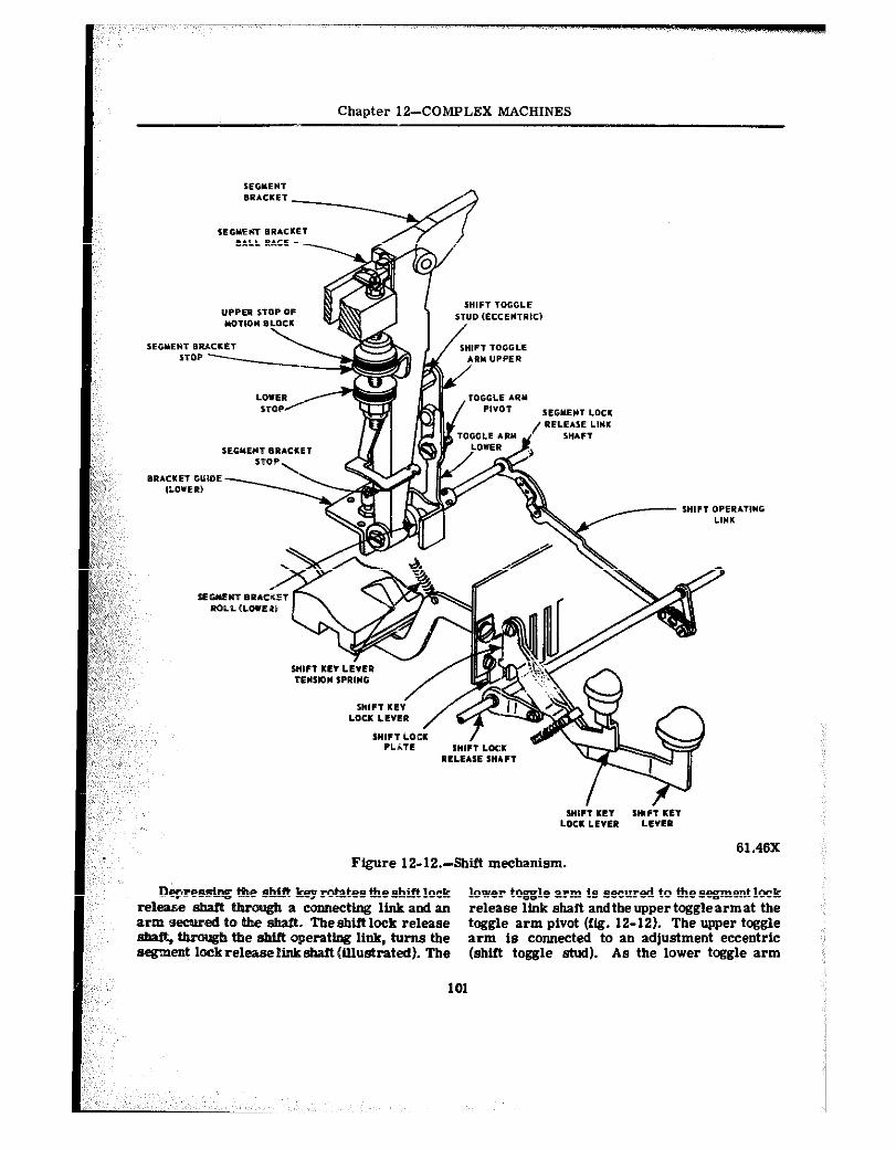
Chapter 12-COMPLEX MACHINES
Figure 12-12.-Shift mechanism. 61.46X
Depressing the shin key rotates the skiff lock lower toggle arm is secured to the segment lock release shaft Uuwgh a connecting link and an release link shaft andtheuppertcgglearmat the arm secured to the &aft. Theshiftlock release toggle arm pivot (ftg. 12-U). The upper toggle -, h the shift operating link, turns the arm is connected to an adjustment eccentric segment lockreleaseiinkshaft(Ulwtated). The (shift toggle stua). As the lower toggle arm
101
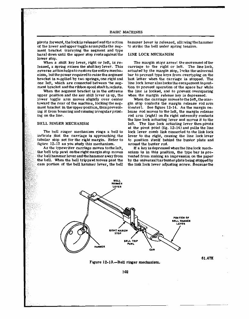
BASIC MACHINES
pivots forward, thelockis released and the action of the lower and upper toggle arme pulls the seg- ment bracket (carrying the segment and type bars) down until the upper stop rests against the lower stop.
When a shift key lever, right or left, is re- leased, a spring raises the shift key lever. This reverse action helpsto restore the entire mecha- nism, but the power requiredto raise the segment bracket is %pplied by two springs, one right and one left, which are connected between +he seg- ment bracket and the ribbon spool shaft brackets.
When the segment bncket is in the extreme upper position and the key shtft lever is up, the lower toggle arm moves slightly over center toward the rear of the machine, locklngthe seg- ment bracket in tbeupperposition, thusprevent- ing it from bouncing and cailsing irregular print- ing on the line.
BELL RINGER MECHAl.~?SX
The bell ringer mechanism rings a bell to in~jieate .&it the carriage is approaching the tabular stop set for the right margin. Refer to figure 12-13 as you study this mechanism.
As the typewriter carriage moves totheleft, the bell trip paw1 onthe right margin stop movee the bellbammerleverandtbehammerawayfrom the bell. When the bell trippawl moves past the cam portion of the bell hammer lever, the bell
hammer lever is released, allowingthehammer to strike the bell under spring tension.
LINE LOCK MECHANISM
The margin stops arres! themovementofthe carriage to the right or left. The line lock, actuated by the margin stop, lwks theuniversal bar to prevent type keys from overtyping on the last letter when the carriage is stopped. The line lock leveralsolockstheescapement inposi- tion to prevent operation of the space bar while the line is locked, and to prevent overspacing when the margin release key is depressed,
When the carriage moves to the left, the mar- gin stop contacts the margin release rod arm (center). See figure 12-14. As the margin re- lease rod moves to the left, the margin release rod arm (right) on its right extremity contacts the line lock actuating lever and moves it to the left. The line lock actuating lever then pivots at the pivot point (fig. 12-14) and pulls the line lock lever comb link connected to the link lock lever to the right, causing the line locklever to position itself behind the bunter plate and around the bunter rod.
If a key is depressed whenthe line lock mech- anism is in this position, the type bar is pre- vented from making an impression on the paper by the universalharbunterplatebeingstoppedby the link lock lever adjusting screw. Becausethe
61.4’lX Figure 12-XX-Bell ringer mechanism.
E02
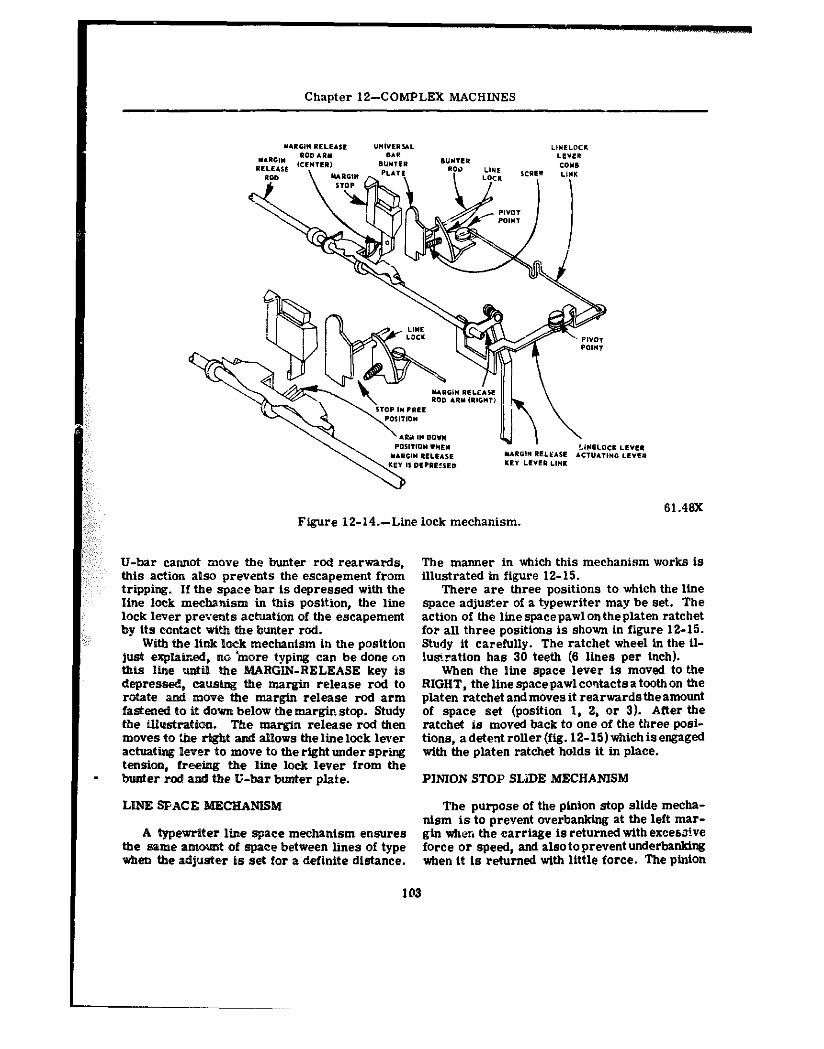
Chapter 12-COMPLEX MACHINES
Figure 12-14.-Line lock mechanism. 61.46X
U-bar cannot move the bunter rod rearwards, this action also prevents the escapement from tripping. If the space bar is depressed with the line lock me&!utim in this position, the line lock lever prevents actuation of the escapement by its contact with the bunter rod.
With the link lock mecbantsm in the position juet explairxd, DO inore typing can be done on this line wtil the MARGIN-RELEASE key is depressed, causing the margtn release rod to rotate and move the margin release rod arm fastened to it down below tbe mar& stop. Study the illustration. The margin release rod then moves to the right and allows thelinelock lever achratii l@ver to move to the right under spring tension, freeimg the line lock lever from the
. bunter rod and the U-bar bunter plate.
The manner in which this mechanism works is illustrated in figure 12-15.
There are three positions to which the line space adjuster of a typewriter may be set. The action of the linespacepawlontheplaten ratchet for all three positions is shown in figure 12-15. Study it carefully. The ratchet wheel In the il- lwnratton has 30 teeth (6 lines per Inch).
When the line space lever is moved to the RIGHT, thelinespacepawlco!ltactsatoothon the platen ratchet and moves it rearwardsthe amount of space set (position 1, 2, or 3). After the ratchet is moved back to one of the three posi- tions, adetentroller(fig. l2-15)tiichisengaged with the platen ratchet holds it in place.
PINION STOP SLiDE MECHANISM
LINE SPACE CHANlSM The purpose of the pinion stop slide mecha- nism is to prevent overbanking at the left mar-
A typewriter line space mechanism ensures gin when the carriage is returned with excess!ve the Balfle zamOua?t of space between lines of type force or speed, and alsotopreventunderbanklng when the adlueter is set for a definite distance. when it is returned with little force. The pinion
103
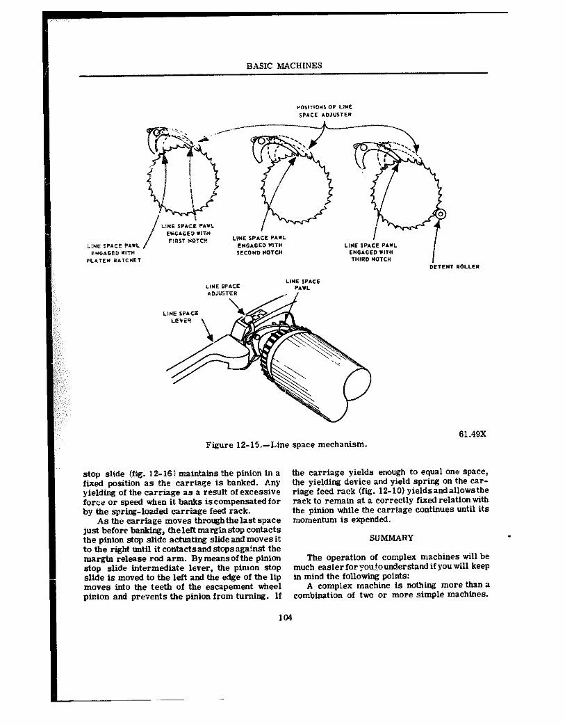
BASIC MACHINES
Figure 12-15.-Line space mechanism. 61.49X
stop slide (fig. 12-16) maintains the pinion in a fixed position as the carriage is banked. Any yielding of the carriage as a result of excessive force or speed when it banks iseompensatedfor by the spring-loaded carriage feed rack.
As the carriage moves throughthelast space just before banktog, tbeleftmarginetop contacts the pinion stop slide a&Wing slide and movee it to the right untti it contactsand stops against the margin release rod arm. By meansofthe pinion stop slide intermediate lever, the pinion stop slide is moved to the left and the edge of the lip movee into the teeth of the escapement wheel pinion and prevects the pinion from turning. If
the carriage yields enough to equal one space, the yielding device and yield spring on the car- riage feed rack (ftg. 12-10) yieldsandallowsthe rack to remain at a correctly fixed relation with the pinion while the carriage continues Until its momentum is expended.
SUMMARY
The operation of complex machines will be much easierforyou~ounderstandifyoutill keep in mind the following points:
A complex machine is nothing more than a combination of two or more simple machines.
104
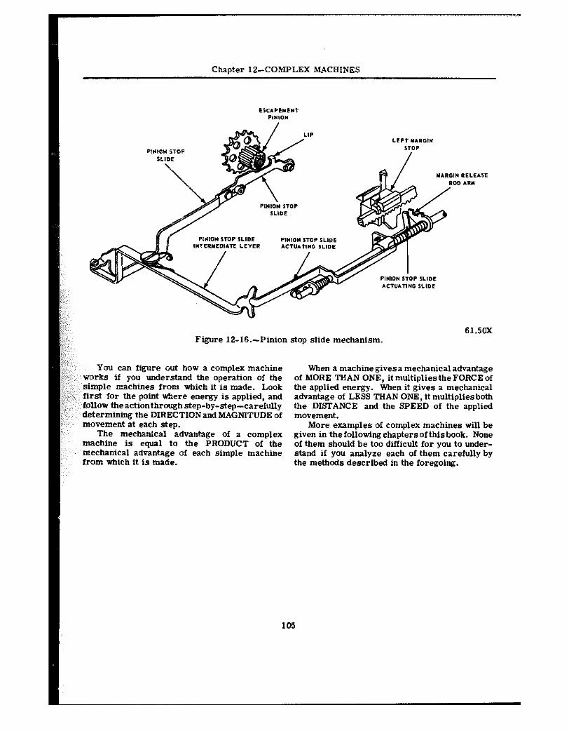
Chapter 12-COMPLEX MACHINES
61.50X Figure 12-l&-Pinion stop slide mechanism.
You can figure out bow a complex machine works if you understand the operation of the
: simple rcaehines from which it is made. Look : first for +&be point where energy is applied, and
‘follow Uleactiontbroughstep-by-step-carehrDy determining the DIRECTIONand MAGNITUDE of movement at each step.
The mechanical advantage of a complex machine is equal to the PRODUCT of the mechanical advantage of each simple machine from which it is made.
When a machinegivesamechanicaladvantage of MORE THAN ONE, it multipliesthe FORCE of the applied energy. When it gives a mechanical advantage of LESS THAN ONE, it multipliesboth the DISTANCE and the SPEED of the applied movement.
More examples of complex machines will be given in thefollowingchaptersofthisbook. None of them should be too difftcult for you to under- stand if you analyze each of them carefully by the methods described in the foregoing.
105
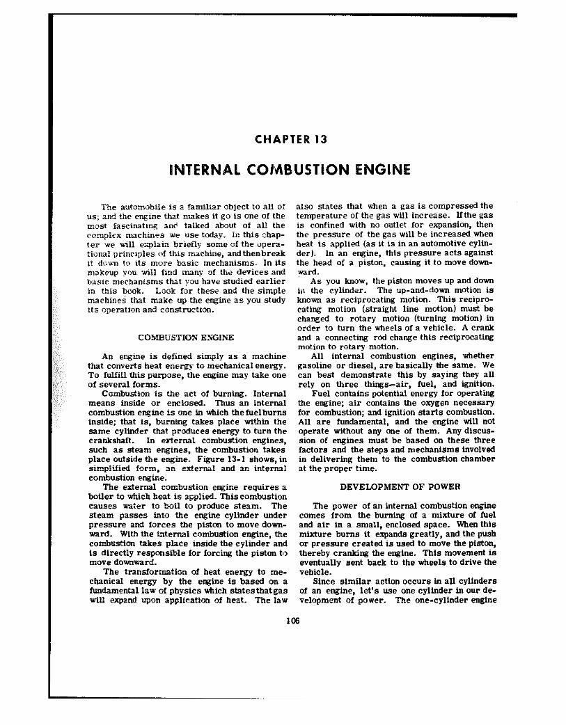
CHAPTER 13
TERNAL COMBUSTION ENGINE
The autarmbile is a famihar object to all of us; and the engine that makes it go is one of the mnst fascinating an6 talked about of all the compP@x machines w@ use today. in this chap- ter ve xvii1 expPaia briefly some of the opera- tional principles of this machine, andthenbreak it down to its more basic mechanisms. In its rnakeuy you will find many of the devices and basic mechanisms that you have studied earlier in this book. Look for these and the simple machinei that make up the engine as you study its operation and ealastruetion.
COSIBeTSTIQN ENGINE
An engine is defined simply as a machine that converts heat energy to mechanical energy. To fulfill this pui-pase, the engine may take one Of several forms.
Combustion is the act of burning. Internal means inside or enclosed. Thus an internal combustion en&w is one in which the fuelburns inside; that is, burning takes place within the same cylinder that phoduees energy to turn the e rankshaft. In external combustion engines, such as steam engines, the combustion takes place outside the engine. Figure 13-I shows, in simplified form, an extcrnd and sr. internal combwtion engine.
The external combustion engine requires a boiler to which heat is applied. Thiscombustion causes az:er to boil to produce steam. The steam passes into the engine cylinder under pressure and forces the piston to move down- ward. With the internal combustion engine, the combustion takes place inside the cylinder and is directly responsible for forcing the piston t,, n~ove downward.
The transformation of heat energy to me- ebanical energy by the engine is based on a fundamental law of physics which states that gas will expand ufmn application of heat. The law
also states that tien a gas is compressed the temperature of the gas will increase. Ifthe gas is confined with no outlet for @xpSnSiOn, then the pressure of the gas will be increased when heat is applied (as it is in an automotive Cylin-
der). In an engine, this pressure acts against the head of a piston, causing it to move down- ward.
As you know, the piston moves up and down in the cvlinder. The up-and-down motion is known a; reciprocating motion. This recipro- cating motion (straight line motion) must be changed to rotary motion (turning mOti0n) in order to turn the wheels of a vehicle. A crank and a connecting rod change this reciprocating motion to rotary motion.
All internal combustion engines, tiether gasoline or diesel, are basically the same. We can best demonstrate this by saying they all rely on three things--air, fuel, and ignition.
Fuel contains potential energy for operating the engine; air contains the oxygen necessary for combustion; and ignition starts combustion. All are fundamental, and the engine till not operate without any one of them. Any discus- sion of engines must he based on these three factors and the steps and mechanisms involv@d in delivering them to the combustion chamber rt the proper time.
DEVELOPMENT OF POWER
The power of an internal combustion engine comes from the burning of a mixture of fuel and air in a small, enclosed space. When this mixture burns it expands greatly, and the push or pressure created is used to move the piston, thereby cranking the engine. This movement is eventually sent back to the wheels to drive the vehicle.
Since similar action occurs in all cylinders of an engine, let’s use one cylinder in our de- velopment of power. The one-cylinder engine
Charter IS--INTERNAL COMWJSTiQN ENGINE
1 81.41
Figure X3-P.--Simple @xternal and internal combustion engine.
consists of Itiwr bask parts as shown in figure but can still slide up and down easily. This up- 13-2. and-down movement, produced by the burningof
First we mwt have a cylinder which is fuel in the cylinder, results in the production of elosed at one end; this cylSnder is similar to a power from the engine. tail metal can. You have already learned that the up-and-
Inside the cylinder is the piston, a movable down movement is called reciprocating motion. metal phtg, M-&h fits snugly into tbe cylinder, This motion must be changed to rotary motion
65.95 Figure 13-Z.-Cylinder, piston, connecting rod, and crankshaft for a one-cylinder engine.
107
BASIC MACHINES
:
so the wheels or track@ of vehicles canbe made to rotate. This &a%@ is accomplished by a crank on Me rranaksbft and a connecting rod which connects between the piston and the crank.
The wan&shaft is a shaft with an offset portion, the crank, wtxich describes a circle 35 the shaR rotates;. The Pop end of the connecting rod is connected to the piston and must there- fore go up and down. The lower end of the con- necting rod is attaczhed to the crankshaft. The lower end of the cannectiag sod also moves up aad dew but, because it is attaebed to the crank- shaft, it must also more in a circle with the crank.
When the pistm of the engine slides down- ward because of the pressure of the expanding gases in the c>%ind@r, the upper end of the con- necting rod moves dowward with the piston, in a straipht line. The lmver end oftbe connecting rcti moves dew% and in a circular motion at the c8me time. This moves the crank and in turn the crank rotates the shaft; this rotation is the desired result. So remember, the crankshaft and connecting rod combination is a mechanism for the purpose oicharagir~ stra’2gbtline, up-and- dam motion to circ*ular, or rotary motion.
BASIC ENOINE STROKES
Each movement of the piston from top to bottom or from bottom to top is calleda stroke. The piston takes two strokes (an upstroke and a downstroke) as the crankshaft makes one com- plete revolution. Oxen the pmton is at the top of a stroke, it is said to be at top dead center (TDC). When the piston is at the bottom of a stroke, it is said to be at bottom dead center (BDC ). These positions are called rock posi- tions and will be discussed further in this ehap- ter under “Timing.” See figure 13-3 and fig- ure 13-7.
The basic engine you have studied so far has had no provisions for getting the fuel-air mix- ture into the cylinder or burned gases out of the cylinder. There are two openings in the en- clos@d end of a cylinder. One of the openings, or ports, permits the mixture of air and fuel to enter and Uleotherportpermitstheburnedgases to escape from the cylinder. The two ports have valves assembled in them. These valves, actuated by the camshaft, close off either one Or the other of the ports, or both of them, dur- ing various stages of engine operation. One of the valves, called tine intake valve, opens to ad- mit a mixture of fuel and air into the cylinder.
108
The fti)llowing pxragraphs give ;I simplified explanation <of the action that takes place within the engine cylinder. This action may bedivided into four parts: the intake stroke, the com- ~ressicn stroke, the pvwer stroke, and the ex- haust stroke. Since these strokes are easy to identify in the operation of a four-cycle engine, that engine is used in the description. This type of engine is also called a four-stroke-Otto- cycle engine, because it was Dr. N.A.Otto who, in 1876, first applied the principle of this en- gine.
INTAKE STROKE
The first stroke in the sequence is called the intake stroke (fig. 13-4). Duringthisstroke, the piston is moving downward and the intake valve is open. This downward movement of the piston produces a partial vacuum in the cylin- der, and air and fuel rush into the cylinder past the open intake valve. This is somewhat the same effect as when you drink through a straw. A partial vacuum is produced in the mouth and the liquid moves up through the straw to fill the Yac”“m.
COMPRESSION STROKE
When the piston reaches bottom dead center at the end of the intake stroke and is therefore at the bott:Jm of the cylinder, the intake valve closes. This seals the upper @i&d of the cylin- der. As the crankshaft continues to rotate, it pushes up, throuah the connecting rod, on the piston. The piston is therefore pushec! upward and compresses the combustible mixture in the cylinder; this is called the compression stroke (fig. 13-4). In gasoline engines, the mixture is compressed to about one-eighth of its original volume. (:n a diesel engine the mixture may be compressed to as little as one-sixteenth of its original volume.) This compression of the air- fuel mixture increases the pressure within the cylinder. Compressing the mixture in this way makes it still more combustible; not only does the pressure in the cylinder go up, but the tem- perature of the mixture also increases.
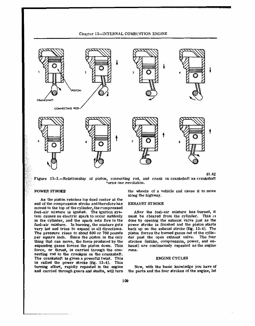
Chaoter 13-INTERNAL COHEWSTION ENGlNE
:;;; ,;;,,- 81.42 ” ; Figure 13-3.-Relationship of piston, connecting rod, and crank on crankshaft as crankshaft
‘urns one revolution.
POWER STROKE the wheels of a vehicle and cause it to move along the highway.
As the piston reaches top dead center at the end of the compression stroke and therefore has EXHAUST STROKE moved to the top of tbecylinder, thecompressed fuel-air mixture is ignited. The ignition sys- After the fuel-air mixture has burned, it tern causes an electric spark to occur suddenly must be cleared from the cylinder. This is in the cylinder, and the spark sets fire to the done by opening the exhaust valve just as the fuel-air mixture. In burning, the mixture gets power stroke is finished and the piston starts very hot and tries to expand in all directions. back up on the exhaust stroke (fig. 13-4). The The pressure rises to about 600 or 700 pounds piston forces the burned gases Out of the cylin- per square inch. Since the piston is the only der past the open exhaust valve. The four thing that can move, tbe force produced by the strokes (intake, compression, power, and ex- expanding gases forces the piston down. This haust) are continuously repeated as the engine force, or thrust, is carried through the eon- runs. “ecting rod to the crankpi” on the crankshaft. The crankshaft is given a powerful twist. This ENGINE CYCLES is called the power stroke (fig. 13-4). This turning effort, rapidly repeated in the engine Now, with the basic knowledge you have of and carried through gears and shafts, will turn the parts and the four strokes of the engine, let
108
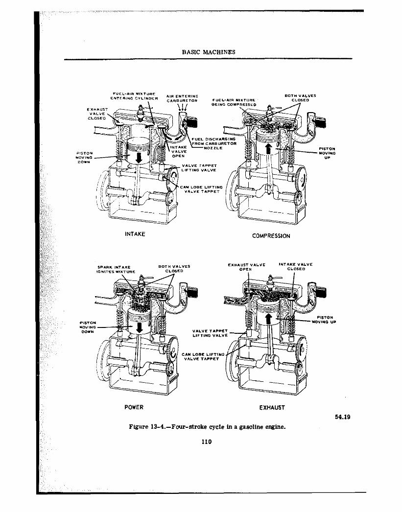
BASIC MACHINES
POWER EXHAUST
Figure 13-4.-Four-stroke cycle in a gasoline engine.
110
54.19
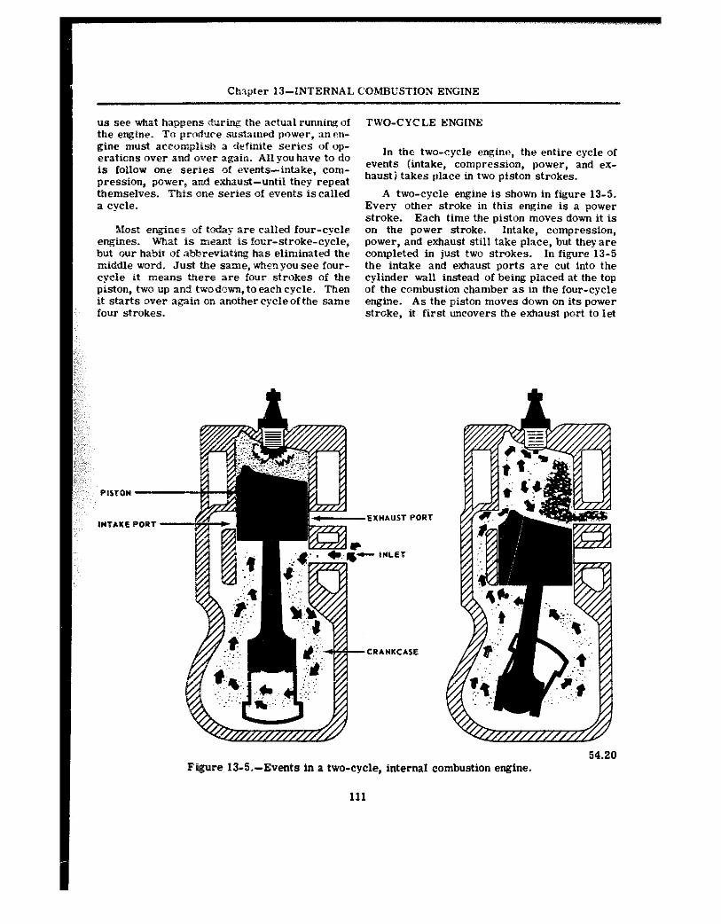
Chxpfer IJ-INTERNAL COMBUSTION ENGINE
us see what happens during the actual running of the engine. To pro&ce swtained pow@*, anen- gine must accomplish 3 definite series of op- erations over and over again. All you have to do is follow one series of events-intake, com- pression, power, and exhaust-until they repeat themselves. This one series of events is called a cycle.
Most engines of to&y are called four-cycle e-ties. U%at is m@ant is four-stroke-cycle, but our habit of abbrevtating has eliminated the middle word. Just the same, when you see four- cvcle it means there are four strokes of the &ton, tw@ up and twodow, to each cycle. Then it starts over again on anothercycleof the same four strokes.
TWO-CYCLX ENGINE
In th@ two-cycle engine, the entire cycle of events (intake, compression, power, and ex- haust j takes place in two piston strokes.
A two-cycle engine is shown in figure 13-5. Every other stroke in this engine is a power stroke. Each time the piston moves down it is on the power stroke. Intake, compression, power, and exhaust still take place, but they are completed in just two strokes. In figure 13-5 the intake and exhaust ports are cut into the cylinder wall instead of being placed at the top of the combustion chamber as in the four-cycle engine. As the piston moves down on its power stroke, it first uncovers the exhaust port to let
Figure 13-%--Events in a two-cycle, internal combustion engine.
111
54.20
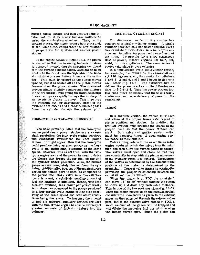
BASIC MACHINES
burned gases escape and then uncovers the in- take port to allow a new fuel-air mixture to enter the eombustim chamber. Then, on the upward stroke, the piston covers bothportsand, at the same ti%e, compresses the new mixture in preparation for anition and another power stroke.
In tbe engine shown in figure 13-5 the piston is shaped so that the incoming fuel-air mixture is directed upward, thereby sweeping out ahead of it the burned exhaust gases. Also, there is an inlet into the eranProase tbhrcugh which the fuel- air rntxture passes before it enters the cylin- der. This inlet is oqened as the piston moves “@vard, but it is sealed off as the piston moves domwsard on the po%er stroke. The downward moving piston slightly compresses the mixture in the crankcase, thus giving the mixture enough pressure to pass rapidly through the intakeport as the piston clears this port. This improves the sweeping-out, or scavenging, effect of the mixture as it enters and clears theburned gases from the cylinder through the exhaust port.
FOUR-CYCLE vs TWQ-CYCLE ENGINES
You have probably noted that the two-cycle engine produces a ~oxver stroke every crank- shaft revolutiom; the four-cycle engine requires two c-t revolutions for each power stroke. It might appear then that the two-cycle could produce twice as much power as thefour- cycle of the same size, operating at the same speed. However, this is not true. With the two.. cycle engine some of the power is used to drive the blower that forces the air-fuel charge into the cylinder under pressure. Also, the burned gases are not eannpletely cleared from the cyl- inder. A~~~t~~~l~, because of the much shorter period the intake port is open (as compared to the period the intake valve in a four-stroke- cycle is open), a relatively smaller amount of fuel-air mixture is admitted. Hence, with less fuel-air Wxture, less power per power stroke is produced as compared to the power produced in a four-stroke cycle engine of like size oper- ating at tie same speed and with other condi- tions being the same. To increase the amount of fuel-air mixture, auxiliary devices are used with the two-stroke engine to ensure delivery of greater amounts of fuel-air mixture into the CYlitkd@r.
1
MULTIPLE-C? LINDER ENGINES
The disrussion so far in this chapter has concerczd a single-ryltnder engine. A single cylinder provides only one power impulse every two cr:mkshaft revolutions in a four-cycle en- gine and is delivering power only one-fourth of the time. To provide for a more continuous flow of power, modern engines use four, six, eight, or more cylinders. The same series of cycles take place in each cylinder.
In a four-stroke cycle six-cylinder engine, for example, the cranks on the crankshaft are set 120 degrees apart, the cranks for cylinders 1 and 6, 2 and 5, and 3 and 4 being in line with each other (fig. 13-6). The cylinders fire or deliver the power strokes in the following or- der: 1-5-3-6-2-4. Thus the power strokesfol- low each other so closely that there is a fairly continuous and even delivery of power to the crankshaft.
TIMING
In a gasoline engine, the valx~es must open and close at the proper times ui?i: regard to piston position and stroke. In addition, the ignition system must produce the sparks at the proper time so that the power strokes can start. Both valve and ignition system action must be properly timed if good engine per- formance is to be obtained.
Valve timing refers to the exact times inthe engine cycle at which the valves trap the mix- ture and then allow the burned gases to escape. The valves must open and close so that they are constantly in step with the piston movement of the cylinder which they control. Theposition of the valves is determined by the camshaft; the position of the piston is determined by the crankshaft. Correct valve timing is obtainedby providing the proper relationship between the camshaft and the crankshaft.
When the piston is at TDC the crankshaft can move 15” to 20” without causing the piston to move up and down any noticeable distance. This is one of the two rock positions(fig. 13-7). When the piston moves up on the exhaust stroke, considerable momentum is given to the exhaust gases as they pass out through the exhaust valve port, but if the exhaust valve closes at TDC, a small amount of the gases will be trapped and will dilute the incoming fuel-air mixture when the intake valves open. Since the piston has
12
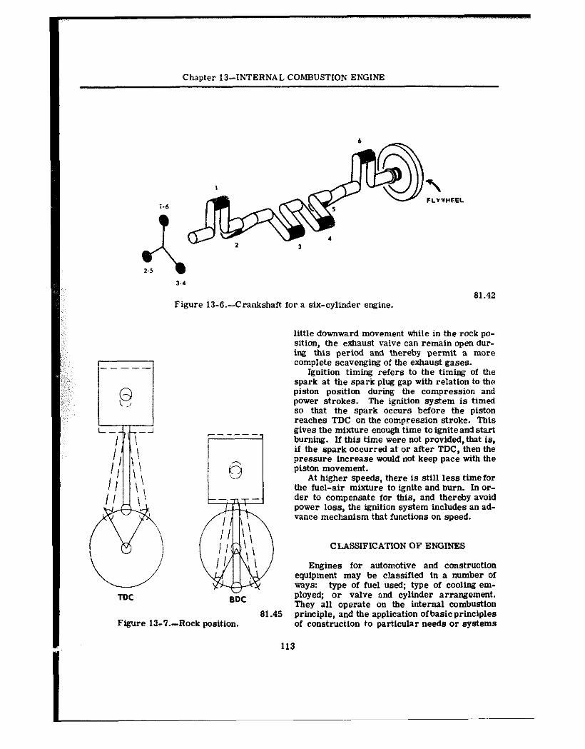
Chapter 13--INTERNAL COMBUSTION ENGINE
TDC
3-4 61.42
Figure 13-6.-Crankshaft for a six-cylinder engine.
c-----
6
BDC
little downward movement while in the rock po- sition, the exhaust valve can remain open dur- ing this period and thereby permit a mure complete scavenging of the exhaust gases.
Ignition timing refers to the timing of the spark at the spark plug gap with relation to the piston position during the compression and power strokes. The ignition system is timed so that the spark occurs before the piston reaches TDC on the compression stroke. This gives the mixture enough time toigniteandstart burning. If this time were not provided, that is, if the spark occurred at or after TDC, then the pressure increase would not keep pace with the piston movement.
At higher speeds, there is still less timefor the fuel-air mixture to ignite and burn. In or- der to compensate for this, and thereby avoid power loss, the ignition system includes an ad- vance mechanism that functions on speed.
CLASSIFICATION OF ENGINES
Engines for automotive and construction equipment may be classified in a number of ways: type Of fuel used; type Of cooling em- ployed; or valve and cylinder arrangement. They all operate on the internal combustion
Figure lL?.--Rock position. 61.45 principle, and the application ofbasicprinciples
of construction to particular needs or systems
113
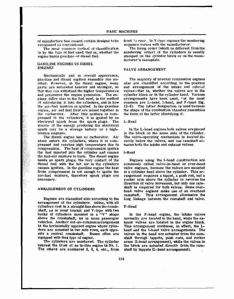
BASIC MACHINES
of manufacture has caused certain designs tobe recognized as conventional.
The mu&t common methti of classification is by the type of fuel used; that is, whether the engine burns gasolinr or diesel fuel.
GASOLINE ENGINES VS DIESEL ENGINES
Mechanically and in overall appearance, gasoline and diesel engines resemble one an- other. However, in the diesel engine, many parts are some=*at heavier and stronger, so that they can withstand the higher temperatures and pressures the engine generates. The en- gines differ also in the fuel used, in the method of intrducing it into the cylinders, and in how thr air-fuel mixtwe is ignited. In the gasoline engine, air and fuel first are mixed together in the carburetor. After this mixture is cum- pressed in the cy’linders, it is ignited by an electrical spark from the spark plugs. The source oi the energy producing the electrical spark may be a storage battery or a high- tension magneto.
The diesel engine has no carburetor. Air alone enters its cylinders, where it is com- pressed and reaches high temperature due to compression. The heat of compression ignites the fuel injected into the cylinder and causes the fuel-air mixture to burn. The diesel engine needs no spark plugs; the very contact of the diesel fuel with the hot air in the cylinders causes ignition. In the gasoline engine the heat from compression is not enough to Ignite the air-fuel mixture, therefore spark plugs are “eWSS2t-y.
ARRANGEMENT OF CYLINDERS
Engines are classified also according to the arrangement of the cylinders: inline, with all cylinders east in a straight lineabove the crank- shaft, as in most trucks; and V-type with two bar&@ of cylinders mounted in a “V” shape above ~&e cranksha ft, as in many passenger vehicles. Another not-so-commonarrangement iS the horizontaliy oppose;l engine whose cylin- ders are mounted in twc side rows, each oppo- site a central crankshaft. Buses often are equipped with this type of engine.
The cylinders are numbered. The cylinder nearest the front of an in-line engine is No. 1. The others are nilmbered 2, 3, 4, etc., from
front to rear. In V-type engines the numbering sequence varies with the manufacturer.
The firing order (which is different fromthe numbering order) of the cylinders is usually stamped on the cylinder block or on the manu- facturer’s nameplate.
VALVE ARRANGEMENT
The majority of internal combustion engines also are classified according to the position and arrangement of the intak@ and .%hzx? valves-that is, whether the valves are in the cylinder block or in the cylinder head. Various arrangements have been used, I.ut the most common are L-head, l-head, and F-head (fig. 13-S). Tke letter designation is used because the shape of the combustion chamber resembles the form of the letter identifying it.
L-Head
In the L-head engines both valves areplaced in the block on the same side of th@ cylinder. The valve-operating mechanism is located di- rectly below the valves, and one camshaft ae- tuates both the intake and exhaust valves.
I-Head
Engines using the I-head construction are commonly called valve-in-head or over-head valve engines, because the valves are noun&d in a cylinder head above the cylinder. This ar- rangement requires a tappet, a push rod, and a rocker arm above the cylinder to reverse the direction of valve movement, but only one cam- shaft is required for both valves. Some over- head valve engines make “se of an overhead camshaft. This arrangement eliminates the long linkage between the camshaft and valve.
F-Head
In the F-head engine, the intake valves normally are located in the head, whiie the @x- haust valves are located in the engine block. This arrang@ment combines, in effect, the L- head and the :-head valve arrangements. The valves in the head are actuated from the cam- shaft through tappets, push rods, and rocker arms (I-head arrangement), while the valves in the block are actuated directly from the cam- shaft by tappets (L-head arrangement).
114
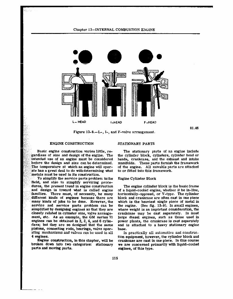
Chapter 13--INTERNAL COMBUSTION ENGINE
L-HEAD I-HEAD F-HEAD
Figure 13-6.-L-, I-, and F-valve arrangement.
ENGINE CONSTRUCTION STATIONARY PARTS
61.46
Basic engine construction varies little, re- gardless of size and design of the engine. The intended us@ of an engine must be considered before the design and size can be determined. The temperature at which an engine will oper- ate has a great deal to do withdetermining what metals must be used in its construction.
To simplii the service parts problem inthe field, and also to simplll servicing proce- dures, the present trend in engine construction and design is toward what is called engine families. There must, of necessity, be many difIerent kinds of engines because there are many kinds of jobs to be done. However, the service and service parts problem can be simplified by designing engines so that they are closely related in cylinder size, valve arrange- ment, etc. As an example, the GM series 71 engines can be obtained in 2, 3, 4, and 6 cylln- ders; but they are so designed that the same pistons, connectfug rods, bearings, valve uper- ding mechanisms and valves can be used in all 4 engines.
Engine construction, in this chapter, will be broken dovm into two categories: stationary parts and moving parts.
The stationary parts of an engine include the cylinder block, cylinders, cylinder head or heads, crankcase, and the exhaust and intake manifolds. These parts furnish the framework of the engine. All movable parts are attached to or fitted into this framework.
Engine Cylinder Block
The engine cylinder block is the basic frame of a liquid-cooled engine, whether it be in-line, horizontally-opposed, or V-type. The cylinder block and crankcase are often cast in one piece which is the heaviest single piece of metal in the engine. (See fig. 13-P). In small engines, where weight is an important consideration, the crankcase may be cast separately. In most large diesel engines, @uch as those used in power plants, the crankcase is cast separately and is attached to a heavy stationary engine base.
In practically all automotive and consb’uc-
tion equipment, however, the cylinder block and crankcase are cast in one piece. In this course we are concerned primarily with liquid-cooled engines, of this type.
115
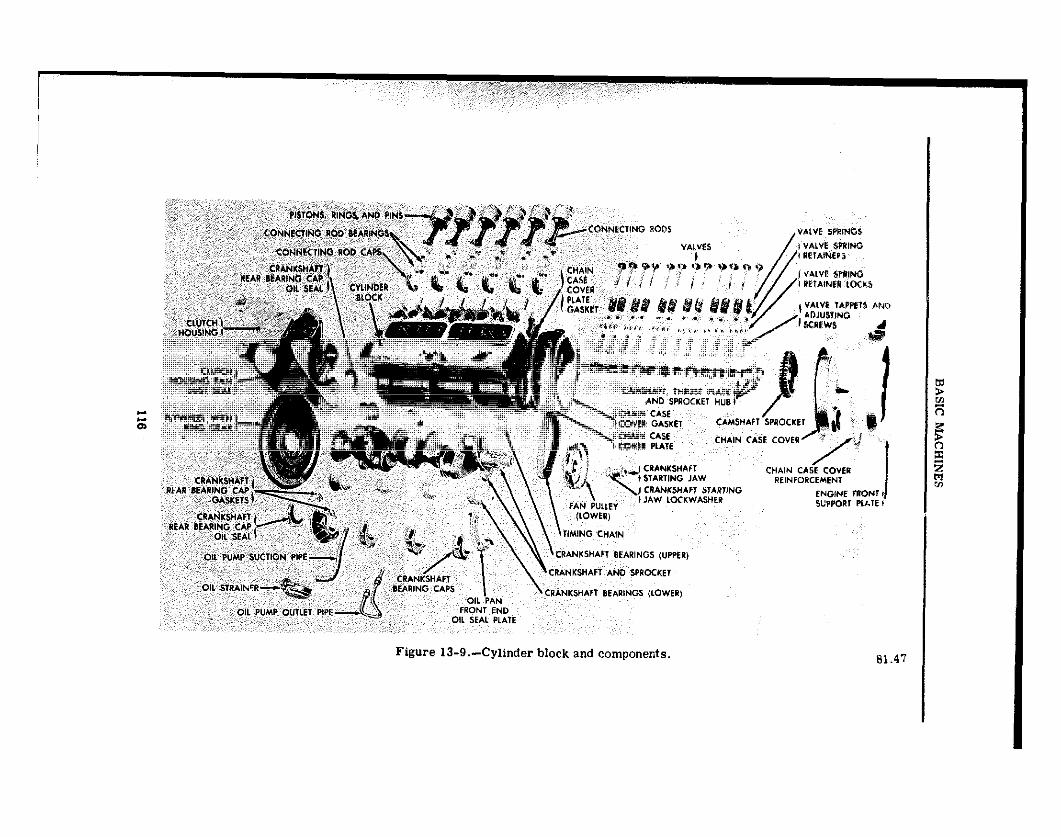
Figure 1%9.-Cylinder block and componer.ts. 81.47
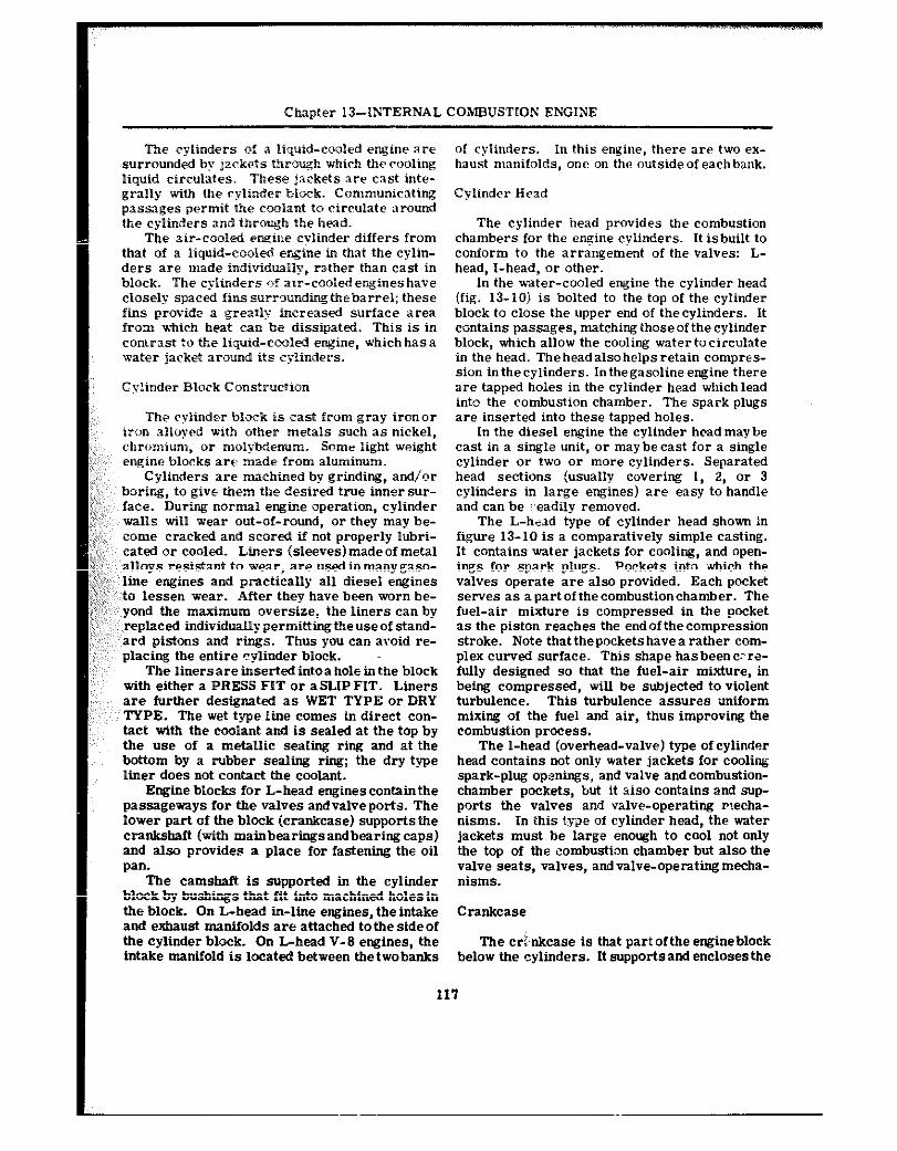
Chapter 13-IhTERNAL COMEK!STIQN EKGGINE
The cylinders of a liquid-eou!ed engine are surrounded by jackets through which the cooling liquid circulates. These jackets are cast inte- grally with the cylinder b&k. Communicating passages permit the cwlant to circulate around the cylinders and through the head.
The air-cooled e~ine cylinder differs from that of a liquid-eooI@d engine in that the cylin- ders are made individually, rather than cast in block. The cylinders *of air-cooled engines have closely spaced fins surrounding thebarrel; these fins provide a greatly increased surface area from which heat an be dissipated. This is in conwast to the liquid-cooled eqine, which has a wafer jacket mvmd its cylinders.
Cylinder Block Construeaion
The cylioder block is cast from gray ironor iron aIio),ed with other metals such as nickel, chromium, or mol@denum. Some light weight engine blocks are made fron aluminum.
Cylinders are maehtned by grinding, and/or boring, to give them the desired true innersur- face. During normaP engine operation, cylinder walls -till wear out-of-round, or they may be- come cracked and scored if not properly lubri- cated or cooled. Liners (sleeves) made of metal alloys resietant to wear, are used in many gaso-
:, line engines and practically all diesel engines to lessen wear. After they have been worn be-
,; yond the maximum oversize, the liners can by ,’ replaced individually perlrmitting the use of stand-
ard pistons and rings. Thus you can avoid re- placing the entire cylinder block.
The liners are inserted intoa hole in the block with either a PRESS FIT or aSLIP FIT. Liners are further designated as WET TYPE or DRY TYPE. The wet type line come@ in direct con- tact with the coolant and is sealed at the top by the uee of a metallic sealing ring and at the bottom by a rubber sealing ring; the dry type liner does not contact the coolant.
Engine blocks for L-head engines contain the passageways for the valves andvalveports. The lower part of the block (crankcase) supportsthe crankshaft (with mainbearingsandbearing caps) and also provides a place for fastening the oil pan.
The camshaft is supported in the cylinder block by bushings that fit into machined holes in the bl&k. On i-head in-line engines, the intake and exhaust manifolds are attached tothe sideof the cylinder block. On L-head V-8 engines, the Intake manifold is located between thetwobanks
of cylinders. In this engine, there are two ex- haust manifolds, one on the outsideof eachbank.
Cylinder Head
The cylinder bead provides the combustion chambers for the engine cylinders. It isbuilt to conform to the arrangement of the valves: L- head, I-head, or other.
In the water-cooled engine the cylinder head (fig. 13-iO! is bolted to the top of the cylinder block to close the upper end of the cylinders. It contains passages, matching those of the cylinder block, which allow the cooling water tocirculate in the head. Theheadalsohelpsretain compres- sion in the cylinders. In the gasoline engine there are tapped holes in the cylinder head whichlead into the combustion chamber. The spark plugs are inserted into these tapped holes.
In the diesel engine the cylinder head may be cast in a Single unit, or maybecast for a single cylinder or two or more cylinders. Separated head sections (usually covering 1, 2, or 3 cylinders in large engines) a-8 easy to handle and can be readily removed.
The L-had type of cylinder head shown in figure 13-10 is a comparatively simple casting. It contains water jackets for cooling, and “pen- ings for spark plugs. Pockets into ~flhich the valves operate are also provided. Each pocket serve@ as a part of the combustion chamber. The fuel-air mixture is compressed in the pocket as the piston reaches the end of the compression stroke. Note that the pockets have a rather com- plex curved surface. This shape hasbeenc-re- fully designed so that the fuel-air mixture, in being compressed, will be subjected to violent turbulence. This turbulence assures uniform mixing of the fuel and air, thus improving the combustion process.
The I-head (overhead-valve) type of cylinder head contains not only water jackets for cooling spark-plug openings, and valve andcombustion- chamber pockets, but it aiso contains and sup- ports the valves and valve-operating Recha- nisms. In this type of cylinder head, the water jackets must be large enough to cool not only the top of the combustion chamber but also the valve seats, valves, andvalve-operatiimecha- nisms.
ClWlkCX3@
The cri;nkcase is that part ofthe engineblock below the cylinders. It supports and encloses the
117
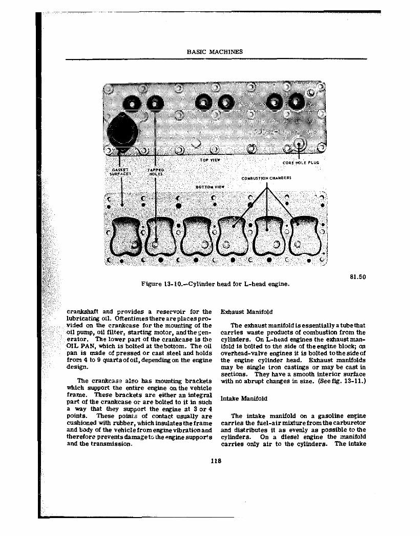
I BASIC MACHINES
Figure 13-10.~Cylinder head for L-head engine. 81.50
crankshaft and provides a reservoir for the lubricating oil. Oftentimestbereareplacespro- vided on the crankcase for the mounting of the oil pump, oil filter, starting motor, andthegen- erator. The lower part of the crankcase is the OIL PAN, which is bolted at thebottom. The oil pan is made of pressed or east steel and holds from 4 to 9 quarts”foiI,dependIngon the engine design.
The crankcase a:@” has mounting brackets which support the entire engtne on the vehicle frame. These brackets are either an integral part of the crankcase or are bolted to it in such a way that they support the engine at 3 or 4 points. These poinis of contact usually are cushioned with rubber, ~~iehineulatestheframe and body Of the vehiciefromenginevibrationand therefore prevents damageto the engine supports and the transmission.
Exhaust Manifold
The exhaust manifold is essentially atube that carries waste products of combustion from the cylinders. On L-head engines the exhaust man- ifold ts bolted to the side of the engine block; on overhead-valve engines it is bolted tothe side of the engine cylinder head. Exhaust manifolds may be single iron castings or may be cast In sections. They have a smooth interior surface with no abrupt changes in size. (See fig. 13-11.)
Intake Manifold
The intake mantfold on a gasoline engine carries the fuel-air mixturefromthecarburetor and distributes it a@ evenly as possible to the cylinders. On a diesel engine the .manifold carries only air to the cylinders. The intake
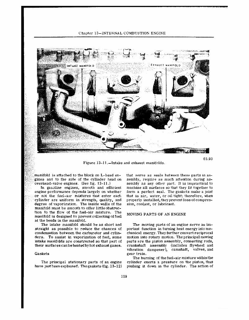
I Chapter I3-NTERNAL COMBUSTION ENGINE
manifold is attached ta the block on L-head en- gines and to the side of the cylinder head on overhead-valve engines. (See fig. 13-11.)
In gasoline engines, smooth and efficient engine performance depends largely on whether or not the fuel-air mixtures that enter each cylinder are uniform in strength, quality, and degree of vaporization. The inside walls of the manifold must be smeolh to offer little obstruc- tion to the flo-v of the fuel-air mixture. The manifold is designed to prevent collecting of fuel at ihe bends in the manifold.
The intake manifold shouid be as short and straight as possible to reduce the chances of condensation b@tween the carburetor and cylin- ders. To assist in vaporization of fuel, some mtake manifolds are constructed so that part of their surfacescanbeheatedbyhot exhaustgases.
Gaskets
The principal stationary parts of an engine have justbeenexplabned. Th@gask@ts(fig. 13-12)
that serve as seals between these parts in as- sembly, require as much attention during as- sembly as any other part. It is impractical to machine all surfaces so that they fit together to Corm a perfect seal. The gaskets make a joint that is air, water, or oil tight; therefore, when properly installed, they prevent loss of compres- sion, coolant, or lubricant.
MOVING PARTS OF AN ENGINE
The moving parts of an engine serve an im- portant function in turning heat energy into me- chanical energy. They further convert reciprocal motion into rotary motion. The principal moving parts are the piston assem.bly, connecting rods, crankshaft assembly (includes flywheel and vibration dampener), camshaft, valves, and gear train.
The burning of the fuel-air mixture withinthe cylinder exerts a pressure on the piston, thus pushing it down in the cylinder. The action of
I 119
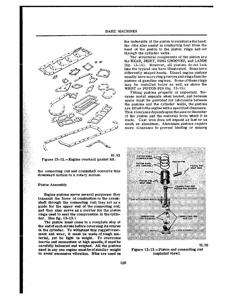
BASIC MACHINES
81.52 Figure 13-12.-Engine overhaul gasket kit.
the connecting rod and crankshaft converts this downward motion to a rotary motion.
Piston Assembly
Engine pistons serve several purposes: they transmit the force of combustion to the crank- shaft through the connecting rod; they act as a guide for the upper end of the connecting rod; and they also serve as a carrier for the piston rings used to seal the compression in thecylin- der. (See fig. 13-13.)
The piston must come to a complete stop at the endof eachstrokebeforereversingitscourse in the cylinder. To withstand this rugged treat- ment and wear, it must be made of tough ma- terial, yet be light in weight. To overcome inertia and momentum at high speeds, it mustbe carefully balanced and weighed. All the pistons used in any one engine mustbeof similar weight to avoid excessive vibration. Ribs are used on
the underside of the piston to reinforce thehead; the ribs also assist in conducting heat from the head of the piston to the piston rings and out throuah the cvlinder walls.
Thk struciural components of the piston are the HEAD. SKIRT. RING GROOVES. and LANDS (fig. 13-l;). However, all pistons do not look like the typical one here illustrated. Some have differently shaped heads. Diesel engine pistons usually have more ring grooves and rings thanthe pistons of gasoline engines. Some of these rings may be installed below as well as above the WRIST or PISTON PIN (fig. 13-15).
Fitting pistons properly is important. Be- cause metal expands when heated, and because space must be provided for lubricants between the pistons and the cylinder walls, the pistons are fitted to the engine with a specified clearance. This elearancedependsuponthe sizeordiameter of the piston and the material from which it is made. Cast iron does not expand as fast or as much as aluminum. Aluminum pistons require more eiearance to prevent binding or seizing
Figure 13-IX-Piston and connecting rod (exploded view).
120
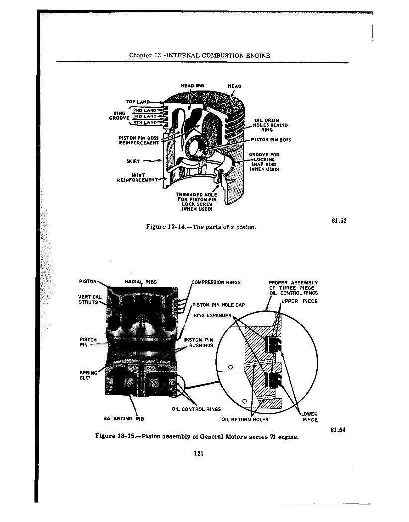
Chapter I3--INTERNAL COMBUSTION ENGINE
Figure 13-14.-The parts of a piston. 81.53
OiL CONTROL RINOS \LOWER
BALANCING RIB OIL RETURN HOLES PIECE
81.54 Figure 13-X-Piston assembly of General Motors series 71 engine.
121
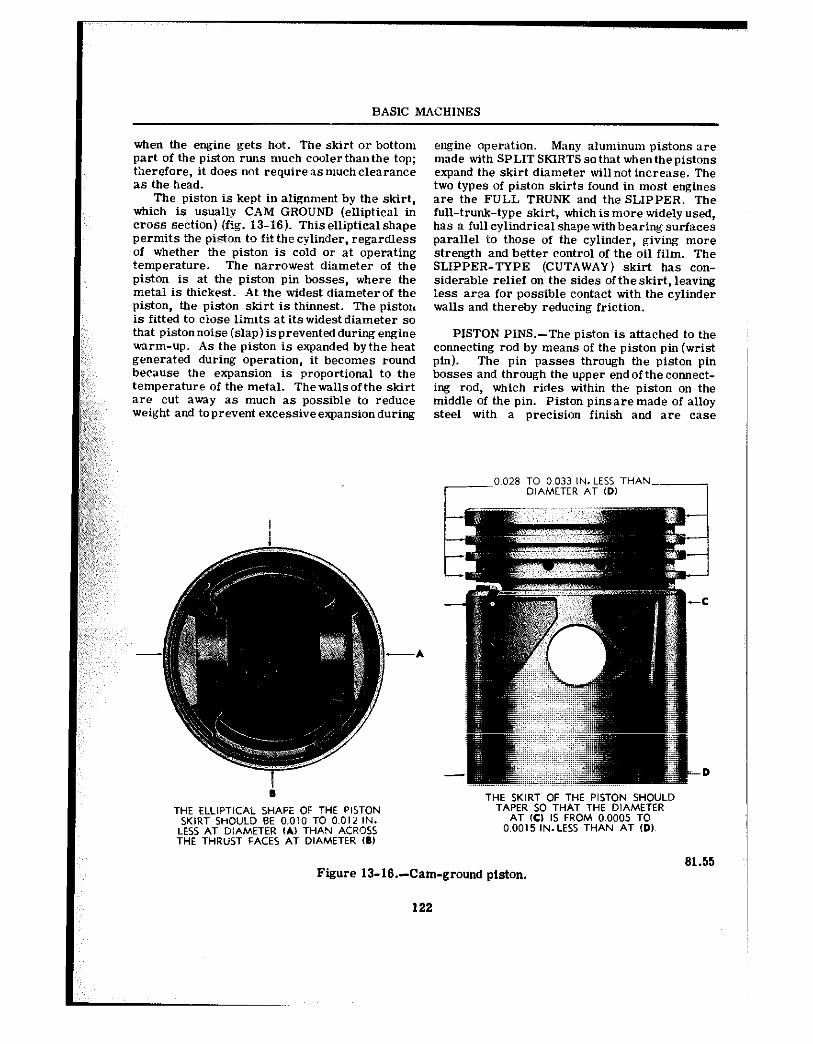
BASIC M4CHINES
when the engine gets hot. The skirt or bottom part of the piston runs much cooler than the top; therefore, it does not requireasmuchclearance as the head.
The piston is kept in alignment by the skirt, which is usually CAM GROUND (elliptical in ~rnss section) (fig. 13-16). Thiselliptical shape permits the piston to fit the cylinder, regardless of whether the piston is cold or at operating temperature. The narrowest diameter of the piston is at the piston pin bosses, where the metal is thickest. At the widest diameterof the piston, the piston skirt is thinnest. The piston is fitted to ciose limits at itswidestdiameter so that piston noise (slap) is prevented during engine warm-up. As the piston is expanded bythe heat generated during operation, it becomes round because the expansion is proportional to the temperature of the metal. Thewallsofthe skirt are cut away as much as possible to reduce weight and toprevent excessiveexpansionduring
engine operation. Many aluminum pistons are made with SPLIT SKIRTS so that whenthe pistons expand the skirt diameter will not increase. The two types of piston skirts found in most engines are the FULL TRUNK and the SLIPPER. The full-trunk-type skirt, which is more widely used, has a full cyllndrica.1 shape withbearing surfaces parallel to those of the cylinder, giving more strength and better control of the oil film. The SLIPPER-TYPE (CUTAWAY) skirt has con- siderable relief on the sides of the skirt, leaving less area for possible contact with the cylinder walls and thereby reducing friction.
PISTON PINS.-The piston is attached to the connecting rod by means of the piston pin (wrist pin). The pin passes through the piston pin bosses and through the upper end of the connect- ing rod, which rides within the piston on the middle of the pin. Piston pinsaremade of alloy steel with a precision finish and are case
-A
81.55
THE ELLlPTiCAL SHAPE OF THE PlSTON SKIRT SHOULD BE 0.010 TO 0.012 IN.
LESS AT DlAMETER ,A, THAN ACROSS THE THRUST FACES AT DIAMETER (0)
Figure 13-16.-Cam-ground piston.
122
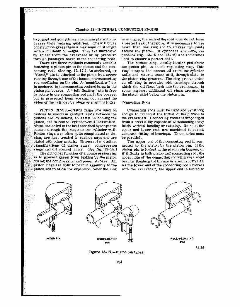
Chapter 13-INTERNAL COMBUSTION ENGINE
hardened and sometimes chromium plated to in- crease their wearing qualities. Their tubular construction gives them a maximum of strength with a minimum of weight. They are lubricated by splash from the crankcase or by pressure through passages bored in the connecting rods.
There are three methods commonly used for fastening a piston pin to the piston and the con- necting rod. (See fig. 13-17.) An anchored, or “fixed,” pin is attached to the pistonbya screw running through one ofthebosses; theconnecting rod oscillates on the pin. A “semifloating” pin is anchored to the connecting rod and turns in the piston pin bosses. A “full-floating” pin is free to rotate in the connectirg rodandinthe bosses, but is prevented from working out against the sides of the cylinder by plugs or snapring locks.
PISTON RINGS.-Piston rings are used on pistons to maintain gastight seals between the pistons and cylinders, to assist in cooling the piston, and to control cylinder-wall lubrication. About one-third of the heat absorbed by the piston passes through the rings to the cylinder wall. Piston rings are often quite complics.ted in de- sign, are heat treated in various ways and are plated with other metals. Thereare twt distinct classifications of piston rings: compression rings and oil control r&x. (See fig. 13-18.)
The principal function of a compression ring is to prevent gases from leaking by the piston
: f~ during the compression aFd power strokes. All ” piston rings are split to germit assembly to the
,‘~ ‘piston and to allow for expansion. Whenthe ring
is in place, the endsof the split joint do not form a perfect seal; therefore, it is necessary to use more than one ring and to stagger the joints around the piston. If cylinders are worn, ex- panders (fig. 13-15 and 13-18) are sometimes used to ensure a perfect seal.
The bottom ring, usually located just above the piston pin, is an oil regulating ring. This ring scrapes the excess oil from the cylinder walls and returns some of it, through slots, to the piston ring grooves. The ring groove under an oil ring is provided with openings through which the oil flows back into the crankcase. In snme engines, additional oil rings are used in the piston skirt below the piston pin.
Connecting Rods
Connecting rods must be light and yet strong enough to transmit the thrust of the pistons to the crankshaft. Connecting rodsaredropforged from a steel alloy capable of withstanding heavy loads without bending or twisting. Holes at the upper and iower ends are machined to permit accurate fitting of bearings. These holes must be parallel.
The upper end of the connecting rod is con- nected to the piston by the piston pin. If the piston pin is locked in the piston pin bosses, or if it floats in both piston and connecting rod, the upper hole of the connecting rod will haves solid bearing (bushing) of bwnze or similar material. As the lower end of the connecting rod revolves with the crankshaft, the upper end is forced to
SEYIFLO*TING
Figure 13-17.-Piston pin types.
F”l.L.FLO*TING PIN
al.56
123
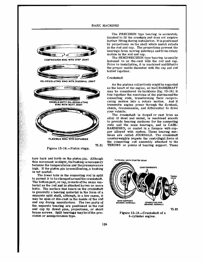
BASIC MACHINES
75.51 Figure 13-18.-Piston rings.
turn back and forth on the piston’pin. Although this movement is slight, thebushing is necessary because the temperatures and thepressuresare high. If the piston pin is semifloating, a bushing is not needed.
The lower hole in the connecting rod is split to permit it to be clampedaround the crankshaft. The bottompart,oreap, ismadeofthe same ma- terial as the rod and is attached bytwo or ma-e bolts. The surface that bears on the crankshaft is generally a bearing material in the form of a separate split shell, although, in a few cases, it may be spun or die-cast in the inside of the i-cd and cap during mamu%x+~re. The two parts of the separate bearing are positioned in the rod and cap by dowel pins, projections, or short brass screws. Split bearings maybeofthe pre- cision or semiprecision type.
124
The PRECISION type bearing is accurately finished to fit the crankpin and does not require further fittingduring installation. It ispositioned by projections on the shell which match reliefs in the rod and cap. The projections prevent the bearings from moving sideways and from rotary motion in the rod and cap.
The SE?&IPRECIS~ON type bearing isus~ally fastened to or die-cast with the rod and cap. Prior to installation, it is machined andfittedto the proper inside diameter with the cap and rod bolted together.
Crankshaft
As the pistons collectively might be regarded as the heart of the engine, so theCRANKSHAFT may be considered its backbone (fig. 13-19). It ties together the reactions of the pistonsandthe connecting rods, transforming their recipro- cating motion into a rotary motion. And it transmits engine power through the flytieel, clutch, transmission, and differential to drive your vehicle.
The crankshaft is forged or cast from an alloy of steel and nickel, is machined smooth to provide bearing surfaces for the connecting rods and the main bearings, and is CASE- HARDENED, or coated in a furnace with cop- per alloyed with carbon. These bearing sur- faces are called JOURNALS. The crankshaft counterweights impede the centrifugal force of the connecting rod assembly attached to the THROWS or points of bearing support. These
75.81 Figure 13-19.-Crankshaft of a
‘I-cylinder engine.
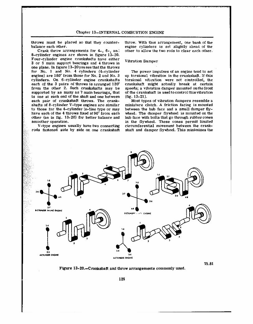
Chapter 13--INTERNAL COMBUSTION ENGINE
throws must be placed so that they counter- balance each other.
Crank throw arrangements for 4-, 6-, an.! B-cylinder engines are show in figure 13-20. Four-cylinder engine crankshafts have either 3 or 5 main support bearings and 4 throws in one plane. In figure 13-20youseethatthe throws far No. 1 and No; 4 cylinders (4-cylinder engine) are 180” from those for No. 2 and No. 3 cylinders. On B-cylinder engine crankshafts each of the 3 pairs of throws is arranged 120” from the other 2. Such crankshafts may be supported by as many as 7 main bearings, that is one at each end of the shaft and one between each pair of crankshaft throws. The crank- shafts of &cylinder V-type engines are similar to those for the 4-cylinder in-line type or may have each of the 4 throws fixed at 90” from each other (as in fig. 13-20) for better balance and smoother operation.
V-type engines usually have two connecting rods fastened side by side on one crankshaft
throw. With this arrangement, one bank of the engine cylinders is set slightly ahead of the other to allow the two rods to clear each other.
Vibration Damper
The power impulses of an engine tend to set up torsional vibration in the crankshaft. If this torsional vibration were not controlled, the crankshaft might actually break at certain speeds; a vibration damper mounted on the front of the crankshaft is used to control this vibration (fig. 13-21).
Most types of vibration dampers resemble a miniature clutch. A friction facing is mounted between the hub face and a small damper fly- wheel. The damper flywheel is mounted on the hub face with bolts that go through rubbercones in the flywheel. These cones permit limited circumferential movement between the crank- shaft and damper flywheel. This minimizes the
Figure 13-20.-Crankshaft and throw arrangements commonly used. 75.81
125
61.62 Figure 13-ZI.-Sectional view of a typical
vibration damper.
effects of the tossborn; vibration in the crank- shzft. Several other types of vibration dampers are used. However, they all operate in es- sentially the same way.
Engine Flywhee!
The P.yv.heel is mounted at the rear of the crankshaft near the rear main bearing. This is usually the longest and heaviest main bearing in the engine, as it must support the weight of ttre flywbee1.
The flyv&tee1 (fig. 13-22) stores up energy Of rutation during power impulses of the engine. It releases this energy b@tweenpow@rimpulses, thus assuring less fluctuation in engine speed and smoother engine operation. The size of the fIywbee1 will vary with the number of cylinders and the general construction of the engine. With a Barge number of eylirders and the consequent
Figure 13-22.-Flywheel. 61.63
overlapping of power impulses, there is less need for a flywheel; consequently, the flywheel can be relatively small. The flywlleel rim carries a ring gear, either integral withthefly- wheel or shrunk on, that meshes with the starter driving gear for cranking the engine. The rear face of the flywheel is usually machined and ground, and acts as one of the pressure surfaces
for the clutch, becoming a part of the clutch assembly.
Valves And Valve Mechanisms
There are two valves for each cylinder in most engines, one intake and one exhaust valve. Since each of these valves operates at different times, it is necessary that separate operating mechanisms be provided for each valve. Valves are normally held closed by heavy springs and by compression in the combustionchamber. The purpose of the valve-actuating mechanism is to overcome the spring pressure and open the valves at the proper time. The valve-actuating mechanism includes the engine camshaft, eam- shaft followers (tappets), pushrods, and rocker arms.
CAMSHAFT.-The camshaft (fig. 13-23) is inclosed in the engine block. It has eccentric lobes (cams) ground on it for each valve in the
BASIC MACHINES
126
Chapter 13-INTERNAL COMRUSTION ENGINE
engine. As the camshaft rotates, the cam lobe moves up under the valve tippet, exerting an upward thrust through the tappet against the V^lV@ stem or a pushrod. Thisthrust Overcom@S the valve spring pressure as well as the gas pressure in the cylinder, causing the v&v@ to open. When the lobe mo”es from under the tappet, the valve s$ring pressure reseats the valve.
On L-, F-, or I-head engines, the camshaft is usually located to one side zd above the crankshaft, while in V-type engines tt isusually located directly above the crankshaft. On the overhead camshaft engine, such as the Murphy diesel, the camshaft is located abovethe cylinder head.
The camshaft of a 4-stroke cycle engine turns at one-half engine speed. It is driven off the crankshaft through timing gears or a timing chain. In the 2-stroke cycle engine the camshaft must tur? at the same speed as the crankshaft in order that each valve may open and close once in each revolution of the engine.
I” most cases the camshaft will uo more than operate the valve mechanism. It may have extra canIs OT gears tit operate fuel pumps, fuel injectors, the ignition distributor, or the lubri- cation pump.
Camshafts are supported in the engine block by journals in bearings. Camshaft bearing journals are the largest machined surfaces on the shaft. The bearings are usually made of bronze and are bushings rather than split bear- ings. The bushings are lubricated by oil cir- culating through drilled passages from the crankcase. The stresses on the camshaft are
61.61 Figure 13-23.-Camshaft and bushings.
127
small, therefore the bushings are not adjustable and require little attention. The camshaft bushings are generally replaced only when the engine requires a complete overhaul.
FOLLOWERS.-Camshaft followers (figs. 13-24 and 13-25) are the parts of the valve- actuating mechanism that contact the camshaft. You will probably hear themcalledvalvetappets or valve lifters. In the L-head engine the follow- ers directly contact the end of the valve stem and have an adjustiug device in them. In the overhead valve engine the followers contact the pushrod that operates the rocker arm. The end of the rocker arm opposite tbn pushrod con- tacts the valve stem. Thevalveadjustingdevice, in this case, is in the rocker arm.
Many engines have self-adjusting valve lifters of the hydraulic type that operate at zero clearance at all times. The operation of one type of hydraulic valve tappet mechanism is shown in figure 13-26. Oil under pressure is forced into the tappet tie” the valve is closed, and this pressure extends the plunger in the tappet se that all valve clearance, oi- lash, is eliminated. When the earn lobe moves around under the tappet and starts to raise it, there will not be any tappet noise. As the lobe starts to
BASIC MACHINES
A-CYLINDER HEAD COVER B-ROCKER ARM C-ROTATOR CAP D-VALVE SPRING E-VALVE GUIDE F-COVER GASKET G-CYLINDER HEAD H-EXHAUST VALVE J-VALVE SPRING CAP K-INTAKE VALVE KEY L-SEAL M-INTAKE VALVE N-CAMSHAFT P-CRANKCASE Q-VALVE TAPPET R-PUSH ROD COVER S-GASKET T-PUSH ROD U-ROCKER ARM SHAFT BRACKET V-ADJUSTING SCREW W-ROCKER ARM SHAFT
61.65 Figure 13-25.-Valve operating mechanism for an overhead valve engine.
raise the tappet, the oil is forced upward in the lower chamber of the tappet. Thisactioncloses the ball check valve so oil cannot escape. Then the tappet acts as though it were a simple, l-piece tappet and the valve is opened. Whenthe lobe moves out from under the tappet and the valve closes, the pressure in thelower chamber of the tappet is relieved. Any slight loss of oil from the lower chamber is then repiaced by the oil pressure from tbeenginelubricatingsystem. This causes the plunger to move up snugly
against the push rod so that any clearance is eliminated.
Timing Gears (Gear Trains)
Timing gears keep the crankshaft and cam- shaft turning in proper relation to one another so that the valves open and close at the proper time. In some engines, sprockets and chains are used.
126
Chapter 13--INTERNAL COMBUSTION ENGINE
61.66 Figure 13-26.-Operation of a hydraulic valve lifter.
The gears or sprockets, as the case may be, in air-cooled engines a blower isgenerallyused of the earn&aft and crankshaft are keyed in to force cool air around the engine cylinders. position so that they cannot slip. Since they are In addition, an exhaust system is providedto keyed to their respective shafts, they can be carry away the burned gases exbaustedfromthe replaced if they become worn or noisy. engine cylinders. These systems will not be
With directlydriventiminggears (fig. 13-27). discussed in this course, however. For further one gear usually has a mark on two adjacent information on them refer to NavPers 10644D, teeth and the other a mark on only one tooth. To Construction Mechanic 3 & 2.
” time the valves properly, it is necessary only to mesh the gears so that the two marked teeth of one gear straddle the single marked tooth of the other.
AUXILIARY ASSEMBLIES
We have discussed the main parts of the engine proper; but there are other parts, both moving and stationary, that are essential to engine operatian. They are not built into the engine itself, but, in most cases, are attached to the engine block or cylinder head.
The fuel system includes a fuel pump and carburetor mounted on the engine. In diesel engines the fuel injection mechanism replaces the carburetor. An electrical system is provided to supply power for starting the engine and also for ignition durmg operation. An efficient cwl- ing system is necessary for operating an internal combustion engine. In water-cooled engines a water pump and fan are used, wile
61.69 Figure13-27.-Timinggearsandtheirmarkings.
129
CHAPTER 14
POWER TRAINS
In chapter 13 we saw how a combination of simple machines and basic mechanisms were utilized in construrtiw the internal combustion engine. In this chapter we will go on from there to learn how the power developed by the ewine is transmitted to perform the work required of it. To illustrate this, we willusethepower train rtysttm as used by the automobile, and most trucks, as a familiar example. In this applica- tion, once again you are to look for the simple macbiaes that make up each of the machines or mechanisms wbichare interconner’ ?d to makeup the power train.
In a vehicle, the mechanism that transmits the power of the engine to the wheels and/or tracks and accessoN equipment is called the power train. In a simple situation, a set of gears or a chair. and sprocket could perform this task, but automotive and construction ve- hicles are not usually designed for such simple operating conditions. They are designed to have great pulling power, to move at high speeds, to travel in reverse as well as forward, and to operate on rough terrain as well ae smooth roads. To meet these widely varying demands, a number of units have been added to the vehicles.
Autom”&iles and light trucks driven by the two rear wheels have a power train consisting of clutch, transmission, propeller shaft, dif- ferential, and driving axles (fig. 14-l).
In 4- and 6-xv&e1 drive trucks, you will find transfer cases with additional drive shafts and live axles. Tractors, shovels, cranes, and other heavy-duty vehicles that move on tracks also have similar power trains. In addition to assemblies that drive sprockets to move the tracks, these vehicles also haveauxiliary trans- missions or power takeoff units which may be used to operate accessory attachments. The propeller shafts and clutch assemblies of these power trains are very much like those used to drive the *eels.
1
THE CLUTCH
The clutch is placed in the power train of motorized equipmeot for two purposes:
First, it provides a meane of disconnecting the power of the engine from the driving wheels and accessory equipment. When the clutch is disengaged, the engine can run without driving the vehicle or operating the accessories.
Second, when the vehicle is started, the clutch allows the engine to take up the load of driving the vehicle or accessories gradually and without shock.
Clutches are located in the power train between the source of power and the operating unit. Usually, they are placed between the engine and the transmission assembly, as shown in figure 14-l.
Clutches generally transmit power from the clutch driving member to the driven member by friction. In the plate clutch, figure 14-2 the driving member or plate, which is secured to the engine flywheel, is gradually brought in contact with the driven member (disc). The contact is made and held by strong springpres- sure controlled by the driver with the clutch pedal. With oniy a light spring pressure, there is little friction between the two members and the clutch is permitted to slip. As the spring pressure increases, friction alsoincreases,and less slippage occurs. When the driver removes his foot from the clutch pedal and full spring pressure is applied, the speed of the driving plate and drivendisc is the same, and all slipping Stops. There is then a direct connectionbetween the driving and driven shafts.
In most clutches, there isadirect mechanical linkage between the clutch pedal and the clutch release yoke lever. On many late model ve- hicles, and on some of the larger units which require great pressure to release the spring, a hydraulic clutch release system is used. A master cylinder (fig. 14-3), similar tothebrake
30
Figure 14-l.-Type of power transmission. 81.114
master cylixder, is attachwl to the clutchpedal. by hydraulic pressure to the slave cylinder, A cylinder, similar to a single-ac;ing brake which in turn actuates the clutch release yoke wheel cylinder, is connfeted to the master lever. cylinder by flexible pressure hwe or metal tubing (fig. 14-3). The slave cylinder is con- TYPES OF CLUTCXES netted to the clutch release yoke lever. Move- ment of the clutch pedal actuates the clutch There are various types of clutches. The master cylinder. This movement is transferred type most used in passenger care and light
Chapter 14-POWER TRAINS
Figure 14-2.-Exploded and cross-section view of a plate clutch.
131
81.175
BASIC MACHINES
81.177 Figure 14-3.-Master cylinder, slave cylinder and connections for standard hydraulic clutch.
trucks is the previously-mentioned plate clutch. The plate clutch is a simple clutch with three phtes, one of which is clamped between the other two. Exploded and cross-sectional views of a plate clutch are show in figure 14-2.
Single Disk Clutch
The driving members of the single disk clutch consist of the flytieel and the driving
(pressure) plate. The driven member consists of a single disk, splined to the clutch shaft and faced on both sides with friction material. When the clutch is fully engaged, the driven disc is firmly clamped between the flywheel and the driving plate by pressure of the clutch springs, forming a direct, nonslipping connection between the driving and driven members of the clutch. In this position, thedrivendisc rotatestheclutch shaft to which it is splined. The clutch shaft is
132
Chapter 14-POWER TRAINS
connected to the driving wheels through the YOU may run into other types of friction transmission, propeller shaft, final drive, dif- clutches such as the lubricated plate clutch and ferential, and live axles. the cone clutch. These types are seldom used
The double disk clutch (fig. 14-4) is sub- on automotive equipment. However, fluid drive stantially the same as the single plate disk is largely replacing the friction clutches in clutch except that another driven diskandinter- automobiles and light trucks, and even in some mediate driving plate is added. tractors.
For informatim on fluid drives (automatic
Multiple Disk Clutch
A rraltiple disk clutch is one having more than three plates or disks. Some have as many -3 11 driving plates and 10 driven disks. Because the multiple disk type has a greater frictional area than a plate clutch, it is besi suited as a steering clutch on crawler type tractors. The multiple disk clutch issometimes used On heavy trucks. In operation, it is very much like the plate clutch and has the same release mechanism. The facings, however, are usually attached to the driving plates rather than
,:, to the driven disks. This reduces the weight of :& the driven disks and keeps them from spinning :;!:;,I after the clutch is released. .; t:,,;;;, ;$j-,,,,
transmissions), refer to Construe& Mechanic 3&2, NavPers 10644-D, chapter 11.
The transmission is part i the power train. It consists of a metal case filled with gears (fig. 14-5), and is usually located in the rear of the engine between the clutch housing and the propeller shaft, as shown in figure 14-1. The transmission. transfers engine power from the clutch shaft to the propeller shaft, and allows the driver or operator to control the power and speed of the vehicle. The transmission shown in figure 14-5 and 14-6 is a sliding gear transmission. Many late model trucks
Figure 14-4.-Double disk clutch-exploded view.
133
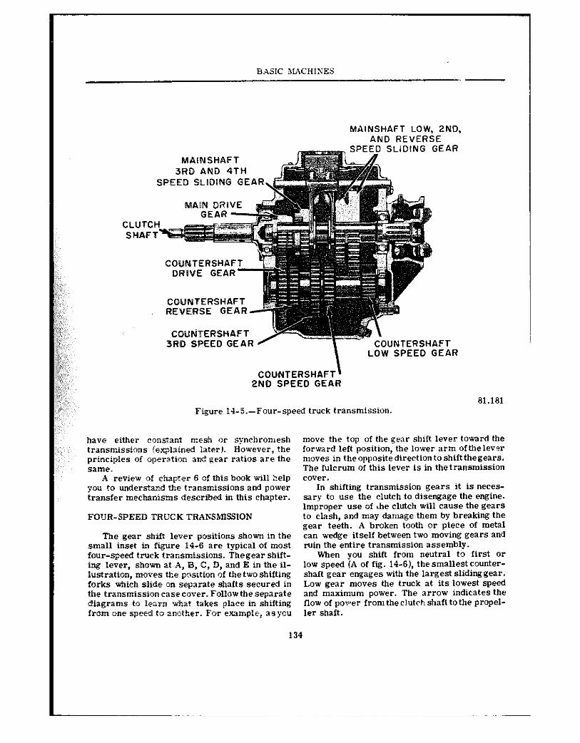
B.ASIC MACHIXES
MAINSHAFT LOW. 2ND. AND REVERSE
SLIDING GEAR
3RD AND 4TH SPEED SLfQlNG GEA
COUNTERSHAF ORWE GEAR
COUNTERSHAFT REVERSE GEAR
CQUtiTERSHAFT 3RD SPEED GEAR NTERSHAFT
SPEED GEAR
COUNTERSHAFT’ 2ND SPEED GEAR
61.161 Figure 14-5.-Four-speed truck transmission.
have either cmstant mesh or synchromesh trilnsmissions iexplained later). However, the principles of aperati~n and gear ratios are the same.
A review of chapter 6 of this book will help you to understand the transmissions and power transfer mechanisms described in this chapter.
FOUR-SPEED TRUCK TRAP;SMISSlON
The gear shift lever positions shown in the small inset in figure 14-6 are typical of most four-speed truck transmissions. Thegear shift- ing lever, shown at A, B, C, D, and E in the il- lustration, moves Me position of the two shifting forks which slide on separate shafts secured in thetransmissionrasecover. Fcllowtheseparate diagrams to Ierrn what takes place in shifting from one speed to another. For example, aeyo”
move the top of the gear shift lever toward the forward left position, the lower arm ofthelevw moves in theoppositedirectiontoshift thegears. The fulcrum of this lever is in thetransmiSsion cover.
In shifting transmission gears it is neces- sary to use the clutch to disengage the engine. Improper use of ihe clutch will cause the gears to clash, and may damage them by breaking the gear teeth. A broken tooth or piece of metal can wedge itself between two moving gears and ruin the entire transmission assembly.
When you shift from neutral to first 01‘ low speed (A of fig. 14-6), thesmallest counter- shaft gear engages with the largest slidinggear. Low gear moves the truck at its lowest speed and maximum power. The arrow indicates the flow of povrer from the clutch shafl tothe propel- ler shaft.
134
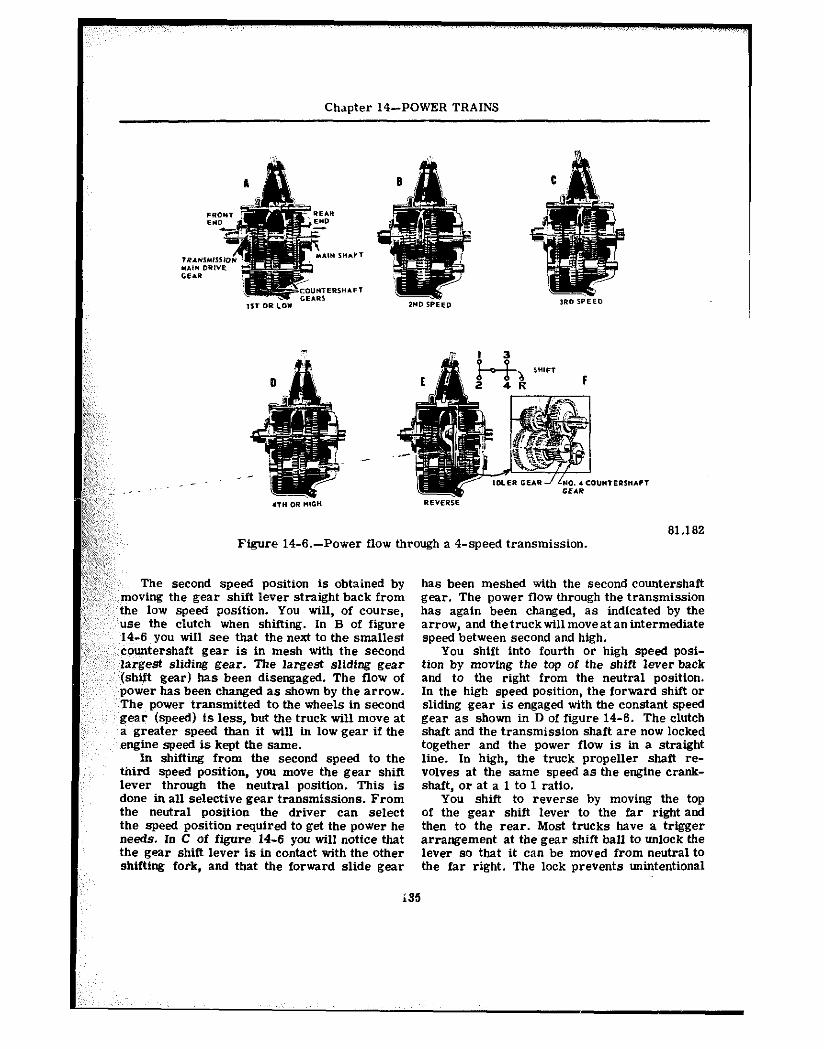
Chapter 14-POWER TRAINS
81.182 Figure 14-6.-Power flow through a 4-speed transmission.
The second speed position is obtained by moving the gear shift lever straight back from the low speed position. You will, of course, use the clutch when shifting. In B of figure 14-6 you will see that the next to the smallest countershaft gear is in mesh with the second largest sliding gear. The largest sliding gear (shift gear) has been disengaged. The flow of power has been chang@d as shown by the arrow. The power transmitted to the wheels in second gear (speed) is less, but the truck will move at a greater speed than it will in low gear if the engine speed is kept the same.
In shifting from the second speed to the third @peed position, you move the gear shift lever through the neutral position. This is done in all selective gear transmissions. From the neutral position the driver can select the speed position required to get the power he needs. In C of figure 14-6 you will notice that the gear shift lever is in contact with the other shifting fork, and that the forward slide gear
has been meshed with the second countershaft gear. The power flow through the transmission has again been changed, as indicated by the arrow, and thetruckwillmoveat anintermediate speed between second and high.
You shift into fourth or high speed posi- tion by moving the top of the shift lever back and to the right from the neutral position. In the high speed position, the forward shift or sliding gear is engaged with the constant speed gear as shown in D of figure 14-6. The clutch shaft and the transmission shaft are now locked together and the power flow is in a straight line. In high, the truck propeller shaft re- volves at the same speed as the engine crank- shaft, or at a 1 to 1 ratio.
You shift to reverse by moving the top of the gear shift lever to the far right and then to the rear. Most trucks have a trigger arrangement at the gear shift ball to unlock the lever so that it can be moved from neutral to the far right. The lock prevents unintentional
BASIC MACHINES
shifts into reverse. Never attempt to shift into reverse until the forward motion of the vehicle has been completely stopped.
In F of figure 14-6, you can see how the idler gear fits into the transmission gear train. In E of figure 14-6, you can see utiat happens vhen you shift into reverse. An additional shifting fork is contacted by the shift lever in the far right position. when the shift to reverseiscompleted, this fork moves the idling gear into mesh with the small countershaft gear and the large sliding gear at the same time. The small arrows in the inset show how the engine power flows through the transmission to m”ve the propeller shaft and the wheels in a reverse direction.
The different combination of gears in the transrnissir~n case makes it possible to change the vehicle speed while the engine speed re- “xains the same. It is all a matter of gear r:i!iils. That is, having large gears drive small pea-s, and small gears drive large gears. If a gear with 100 teeth drives a gear with 25 teeth, the small gear wil? travel four times as fast as the larg& one. You have stepped up the speed. Now, let the smail gear drive the large gear, and the large gear wiI1 make one revolution for every four of the small gear. You have re- duced apeed, and the ratio of gear reduction is 4to1.
In the truck transmission just described, the gear reduction in low gear is 7 to 1 from the engine to the propeller shaft. In high gear the ratio is 1 to 1, and the propeller shaft turns at the same speed as the engine. This holds true for most transmissions. The second and third speed positions provide intermediate gear re- ductions between low and high. The gear ratio in second speed is 3.48 to 1, andin third is 1.71 to 1. The gear reduction orgear ratio in reverse is about the same as it is in low gear, and the propeller shaft makes one revolution for every seven revolutio”s Of the engine.
All transmissions do not have four speeds forward, and the gear reductions at the various speeds are “Et nscessariIy the same. Pas- senger cars, for example, usually have only three forward speeds and one reverse speed. Their gear ratios are about 3 to 1 in both low and reverse gear combinations. You must re- member, the gear reduction in the transmission is only between the engire and the propeller shaft. Another reduction gear ratio is provided in the rear axle assembly. Ifyouhavea common rear axle ratio of about 4 to 1, the gear reduc- tion from the engine of a passenger car to the
rear wheels i? low gear would beapproximately 12 to 1. In high gear the ratio would be 4 to 1 as there would be no reduction of speed in the transmission.
CONSTANT MESH TSANSMISSION
To eliminate the noise developed in the old- type spur-tooth gears used in the sliding gear transmission, the automotivemanufacturersde- veloped the constant-mesh transmission which contains helical gears.
In this type of transmission certaincounter- shaft gears are constantly in mesh wit5 the main shaft gears. The main shaft meshinggears are arranged so that they cannot move endwise. They are supported by roller bearings so that they can rotate independently of the main shaft (figs. 14-7 and 14-S).
In operation, when the shift lever is moved to third, the third and fourth shifter fork moves the clutch gear (A, fig. 14-S) toward the third speed gear (D, fig. 14-S). This en- gages the external teeth of the clutch gear with the internal teeth of the third speed gear. Since the third speed gear is rotating withthe rotating countershaft gear, the clutch gear must also ro- tate. The clutch gear is splined to the main shaft, and therefore the main shaft rotates with the clutch gear. This principle is carried out when the shift lever m”ves from one speed to the next.
Constant-mesh gears are seldom used for all speeds. Common practice is touse such gears for the higher gears, with sliding gears for first and reverse speeds, or for reverse only. when the shift is made to first or reverse, the first and reverse sliding gear is moved to the left on the main shaft. The inner teeth of the sliding gear mesh with the main shaft first gear.
SYNCHROMESH TRANSMISSION
The synchromesh transmission is a type of constant-mesh transmission that permits gears to be selected without clashing, by synchronizing the speeds of mating parts before they engage. It employs a combination metal-to-metal friC- tion cone clutch and adogorgearpositive clutch to engage the main drive gear and second-speed main shaft gear with the transmission main shaft. The friction c”“e clutch engages first, bringing the driving and driven members to the same speed, after which the dog clutch engageseasily without clashing. This process is accomplished
136
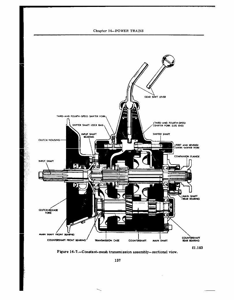
Chapter 14-PO-WER TRAINS
CO”NIBKW FROM IIfAmNG / I- i mANWSS(ON c&f CO”NIIISH*Fl MAIN S”AA REAR BEARING e1.183
Figure 14-‘7.-Constant-mesh transmission assembly-sectional view.
137
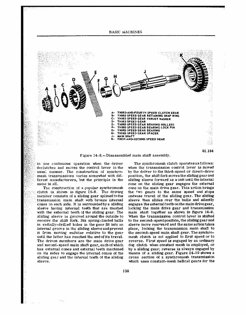
BASIC ILL4CHIr;ES
gz,’ 81.184 @;j Figure 14-S.-Disassembled main shaft assembly. !&>& p<;j$ t*<. g;,;;;:, in one continuous operation when the driver The synchromesh clutch opelatesasfollows: n
2;;;; ” declutches ar.d moves the control lever in the when the transmission control lever iS mOVed
;:,;,, usual manner. The construction of synchro- by the driver to the third-speed or direct-drive mesh transmissions varies somewhat with dif- position, the shift fork moves the sliding gear and ferent manufacturers, but the principle is the sliding sleeve forward as a unit until the internal same in all. cone on the sliding gear engages the external
The construction of a popular synchromesh cone on the main drive gear. This action brings ‘~, clutch is shown in figure 14-9. The driving the two gears to the same speed and stops
member consists of a sliding gear splined to the endwse travel of the sliding gear. The sliding transmission main shaft with bronze internal sleeve then slides over the balls and silently cones OR each side. It is surrounded by a sliding engages the external teeth on the main drive gear, sleeve bavLz internal teeth that are meshed locking the main drive gear and transmission with the external teeth of the sliding gear. The main shaft together as shown in figure 14-9. sliding sleeve is grooved around the outside to When the transmission control lever is shifted receive the shift fork. Six spring-loaded balls to the second-speedposition, the sliding gear and in radially-drilled holes in the gear fit into an sleeve move rearward aud the sameaction takes internal groom-e in the sliding sleeveandprevent place, locking the transmission main shaft to it from moving endwtse relative to the gear the second-speed main shaft gear. The synchro- until the latter has rached the endof its travel. mesh clutch is not applied to first speed or to The driven members are the main drive gear reverse. First speed is engaged by an ordinary and second-speed main shaft gear, each of which dog clutch when constant mesh is employed, or has external cones and external teeth machined by a sliding gear; reverse is always engaged by on its sides to engage the internal cones of the means of a sliding gear. Figure 14-10 shows a sliding gear and the internal teeth of the sliding cross section of a synchromesh transmission sleeve. which uses constant-mesh helical gears for the
138
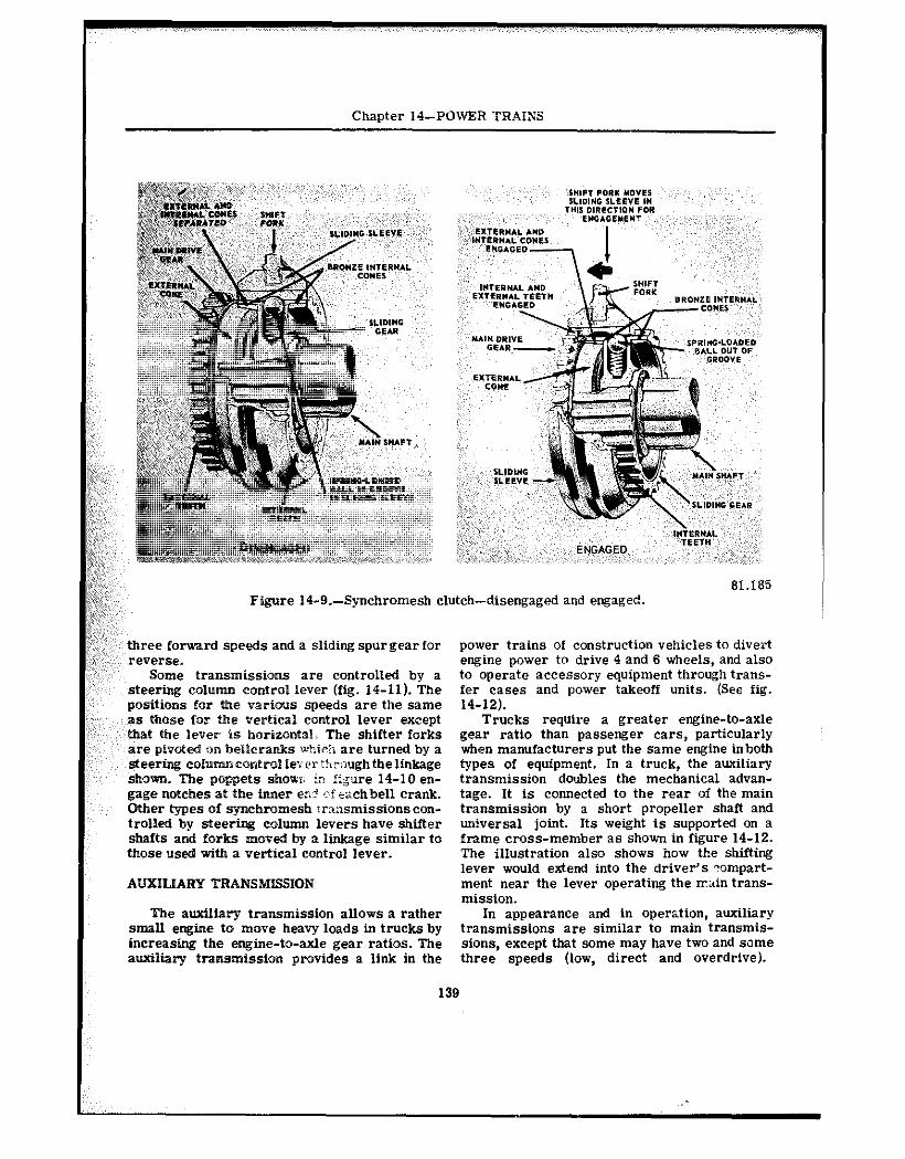
Chapter I4-POWER TRAINS
61.186 Figure I4-9.-Synchromesh clutch-disengaged and engaged.
three forward speeds and a sliding spur gear for reverse.
Some transmissions are controlled by a steering column control lever (fig. 14-11). The positions for the various speeds are the same as those for the vertical control lever except that the lever is horizontal. The shifter forks are pivoted cm belleranks Mirii are turned by a steering eolunmeontrolPe;er Woughthelinkage shown. The ets slmwr; in figure 14-10 en- gage notches at the inner ear’ cfiachbell crank. Other types of synchromesh rrwsmissions con- trolled by steering eohmm levers have shifter shafts and forks moved by a linkage similar to those used with a vertical control lever.
AUXILIARY TRANSMISSIOh’
The auxiliary transmission allows a rather small engine to move heavy loads in trucks by increasing the engine-to-axle gear ratios. The auxiliary transm$ssion provides a link in the
power trains of construction vehicles to divert engine power to drive 4 and 6 wheels, and also to operate accessory equipment through trans- fer cases and power takeoff units. (See fig. 14-12).
Trucks require a greater engine-to-axle gear ratio than passenger cars, particularly when manufacturers put the same engine inbotb types of equipment. In a truck, the auxiliary transmission doubles the mechanical advan- tage. It is connected to the rear of the main transmission by a short propeller shaft and uriiversal joint. Its weight is supported on a frame cross-member as shown in figure 14-12. The illustration also shows how the shifting lever would extend into the driver’s ?ompart- ment near the lever operating the main trans- mission.
In appearance and in operation, auxiliary transmissions are similar to main transmis- sions, except that some may have two and sane three speeds (low, direct and overdrive).
139
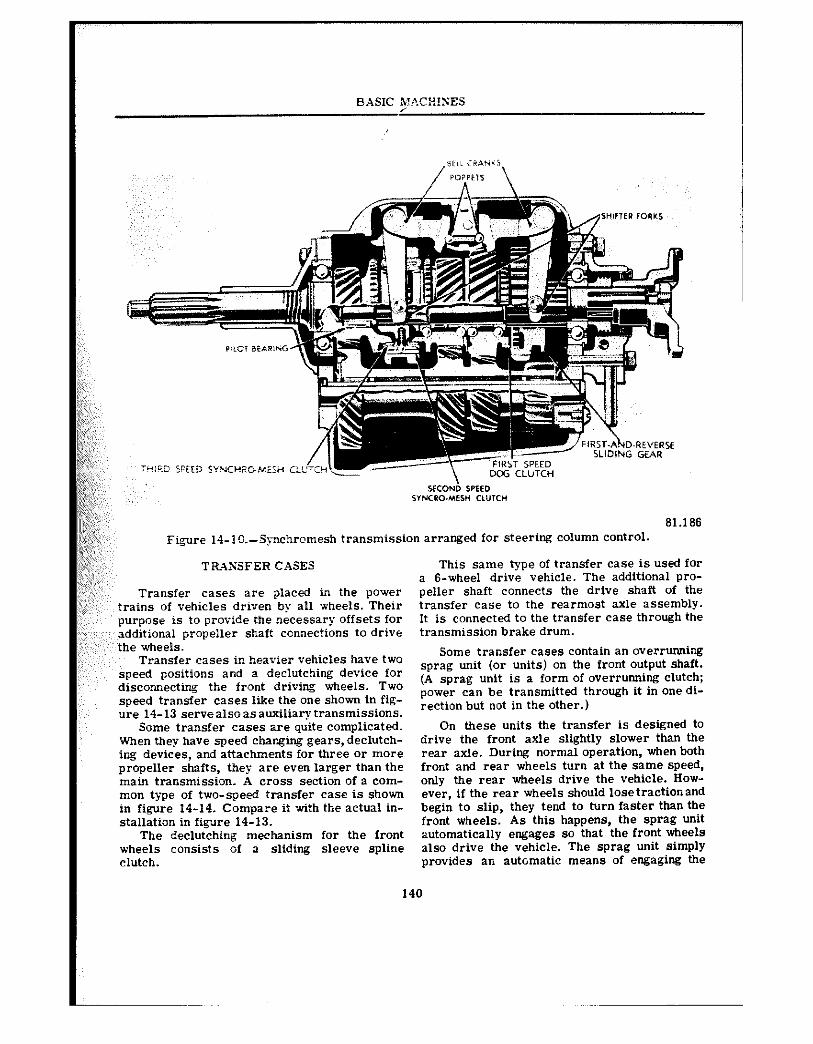
BASIC MT%CHIKES /
NJ;;; I;:;,
IL ~, j@j,j: II@,+;;;,,, pJj%y;,
THi!x SPSED w4xRC.MiSH C:L yfi;,; ,’ *$@a$; #&;:$:, ~i<*j& g+, S”N‘RO.MESH CLUTCW
I@;;; 61.166 ,&g I”$;;;~)~ Figure 14-10.~Siynchromesh transmission arranged for steering column COntrOl. &,~
TRXGSFER CASES This same type of transfer case is used for
z,:y;, a B-wheel drive vehicle. The additional pro- :,: ,:, Transfer cases are placed in the power peller shaft connects the drive shaft of the
trains of vehicles driven by all wheels. Their transfer case to the rearmost axle assembly. purpose is to provide ihe necessary offsets for It is connected to the transfer case through the additional propeller shaft connections to drive transmission brake drum. the wheels.
Transfer cases in heavier vehicles have two Some transfer cases contain an overrunning
speed positions and a declutching device for sprag unit (or units) on the front output shaft.
disconnecting the front driving wheels. Two (A sprag unit is a form of overrunning clutch;
speed transfer cases like the one shown in fig- power can be transmitted through it in one di-
ure 14-13 s@rv@a?soasauxiliary transmissions. rection but not in the other.)
Some transfer eases are quite complicated. On these units the transfer is designed to When they have speed changing gears, declutch- drive the front axle slightly slower than the ing devices, and attachments for three or more rear axle. During normal operation, when both propeller shafts, they are even larger than the front and rear wheels turn at the same speed, main transmission. A cross section of a com- only the rear wheels drive the vehicle. How- man type of two-speed transfer case is shown ever, if the rear wheels should losetractionand in figure 14-14. Compare it with the actual in- begin to slip, they tend to turn faster than the stallation in figxre 14-i3. front wheels. As this happens, the sprag unit
The declutching mechanism for the front automatically engages so that the front wheels wheeis consists of 3 sliding sleeve spline also drive the vehicle. The sprag unit Simply clutch. provides an automatic means of engaging the
140
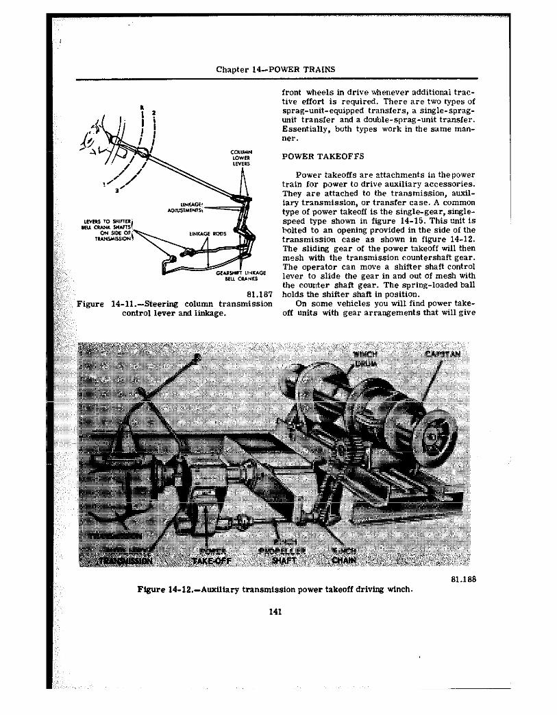
Chanter 14-POWER TRAINS
front wheels in drive whenever additional trac- tive effort is required. There are two types of sprag-unit-equipped transfers, a single-sprag- unit transfer and a double-sprag-unit transfer. Essentially, both types work in the same man- ner.
POWER TAKEOFFS
Po;ver takeoffs are attachments in thepower train for power to drive auxiliary accessories. They are attached to the transmission, auxil- iary transmission, or transfer case. A common type of power takeoff is the single-gear, single- speed type shown in figure 14-15. This unit is bolted to an opening provided in the side of the transmission case as shown in figure 14-12. The sliding gear of the power takeoff will then mesh with the transmission countershaft gear. The operator can move a shifter shaft control lever to slide the gear in and out of mesh with the counter shaft gear. The spring-loaded ball
81.181 holds the shifter shaft in position. Figure 14-ll.-Steering column transmission On some vehicles you will find power take-
control lever and linkage. off units with gear arrangements that will give
Figure 14-12.-Auxiliary transmission power takeoff driving winch.
141
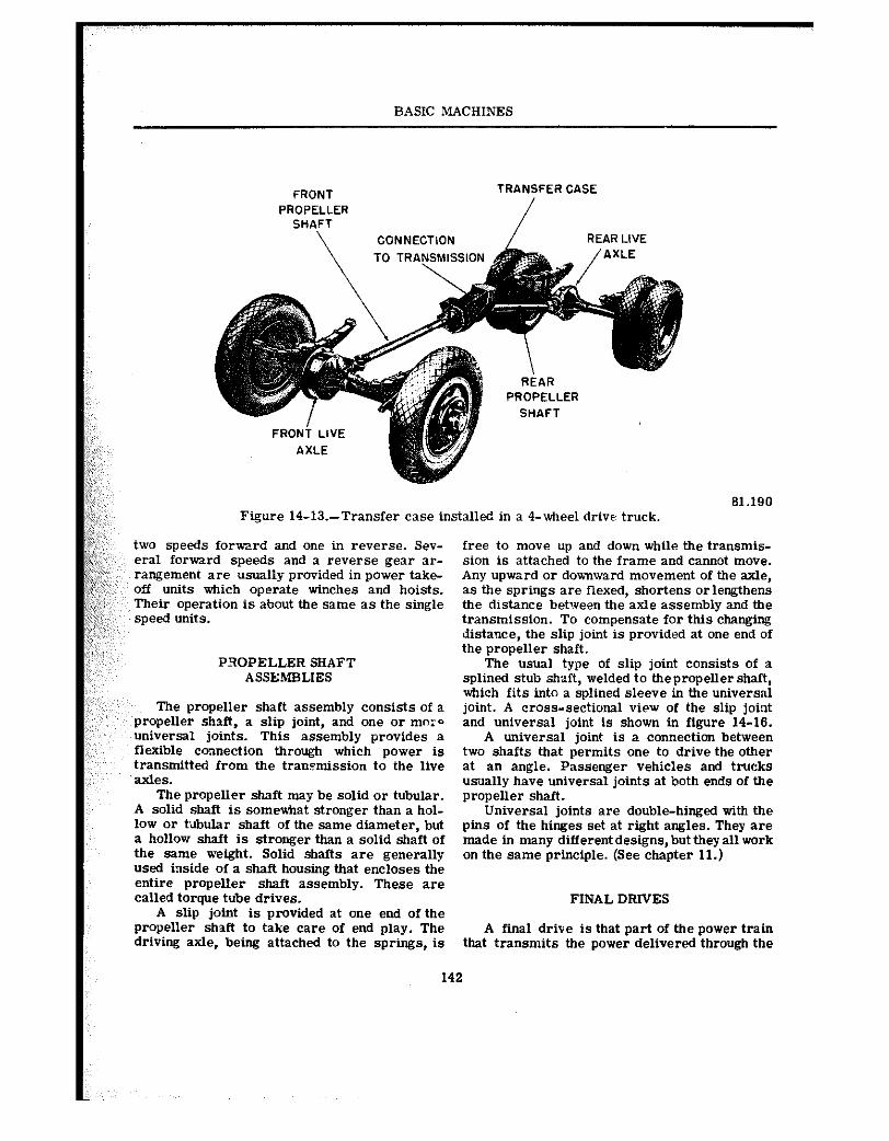
BASIC NIACHINES
FRONT TRANSFER CASE
PROPELLER SHAFT
\ CONNECTION REAR LIVE
PROPELLER
SHAFT
Figure 14-13.-Transfer case installed in a 4-wheel drive truck. 61.190
two speeds forward and one in reverse. Sev- eral forward speeds and a r@v@r~@ gear ar- rangement are usually provided in power take- off units which operate winches and hoists. Their operation is about the same as the single speed units.
PROPELLER SHAFT ASSEMBLIES
The prop@ller shaft assembly consists of a propeller shaft, a slip joint, and one or tnor- universal joints. This assembly provides a flexible connection through which power is transmitted from the transmission to the live axles.
The propeller shaft may be solid or tubular. A solid shaft is somewhat stronger than a hol- low or tilbular shaft of the same diameter, but a hollow shaft is stronger than a solid shaft of the same weight. Solid shafts are generally used inside of a shaft housing that encIoses the entire propeller shaft assembly. These are called torque tube drives.
A slip joint is provided at one end of the propeller shat? to take care of end play. The driving axle, being attached to the springs, is
free to move up and down while the transmis- sion is attached to the frame and cannot move. Any upward or downward movement of the axle, as the springs are flexed, shortens orlengthens the distance between the axle assembly and the transmission. To compensate for this changing distance, the slip joint is provided at one end of the propeller shaft.
The usual type of slip joint consists of a splined stub shzzft, welded to thepropeller shaft, which fits into a splined sleeve in the universnl joint. A cross-sectional view of the slip joint and universal joint is shown in figure 14-16.
A universal joint is a connection between two shafts that permits one to drive the other at an angle. Passenger vehicles and trucks usllally have universal joints at both ends of the propeller shaft.
Universal joints are double-hinged with the pins of the hinges set at right angles. They are made in many different designs, but they all work on the same principle. (See chapter 11.)
FINAL DRNES
A final drive is that part of the power train that transmits the power delivered through the
142
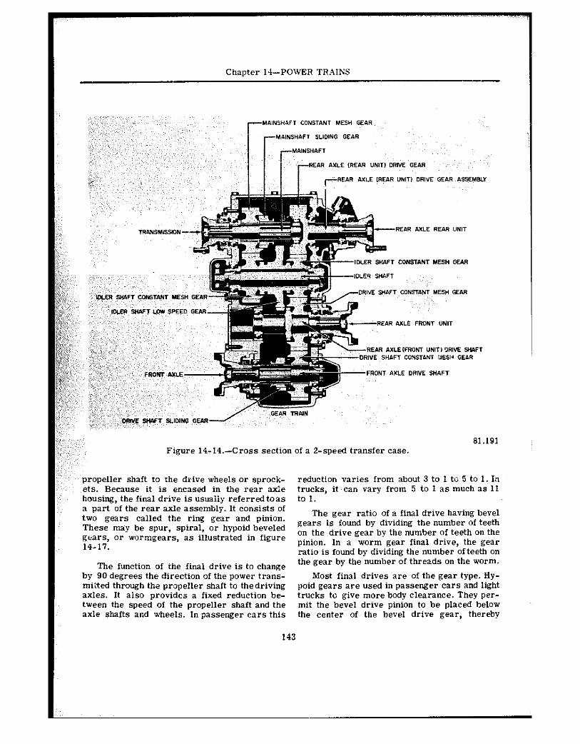
Chapter 14-POWER TR,ZIXS
81.191 Figure 14-14.-Cross section of a 2-speed transfer case.
propeller shaft to the drive wheels or sprock- reduction varies from about 3 to 1 to 5 to 1. In ets. Because it is encased in the rear axle trucks, it can vary from 5 to 1 as much as 11 housing, the final drive is usuaily referred toas to 1. a part of the rear axle assembly. It consists of two gears called the ring gear and pinion.
The gear ratio of a final drive having bevel
These may be spur, spiral, or hypoid beveled gears is found by dividing the number of teeth
gears, or wormgears, as illustrated in figure on the drive gear by the number of teeth on the
14-17. pinion. In a worm gear final drive, the gear ratio is found by dividing the number of teeth on
The function of the final drive is to change the gear by the number of threads on the worm.
by 90 degrees the direction of the power trans- Most final drives are of the gear type. Hy- miSted through the propeller shaft to thedriving poid gears are used in passenger cars and light axles. It also provides a fixed reduction be- trucks to give more body clearance. They per- tween the speed of the propeller shaft and the mit the bevel drive pinion to be placed below axle shafts and wheels. In passenger cars this the center of the bevel drive gear, thereby
143
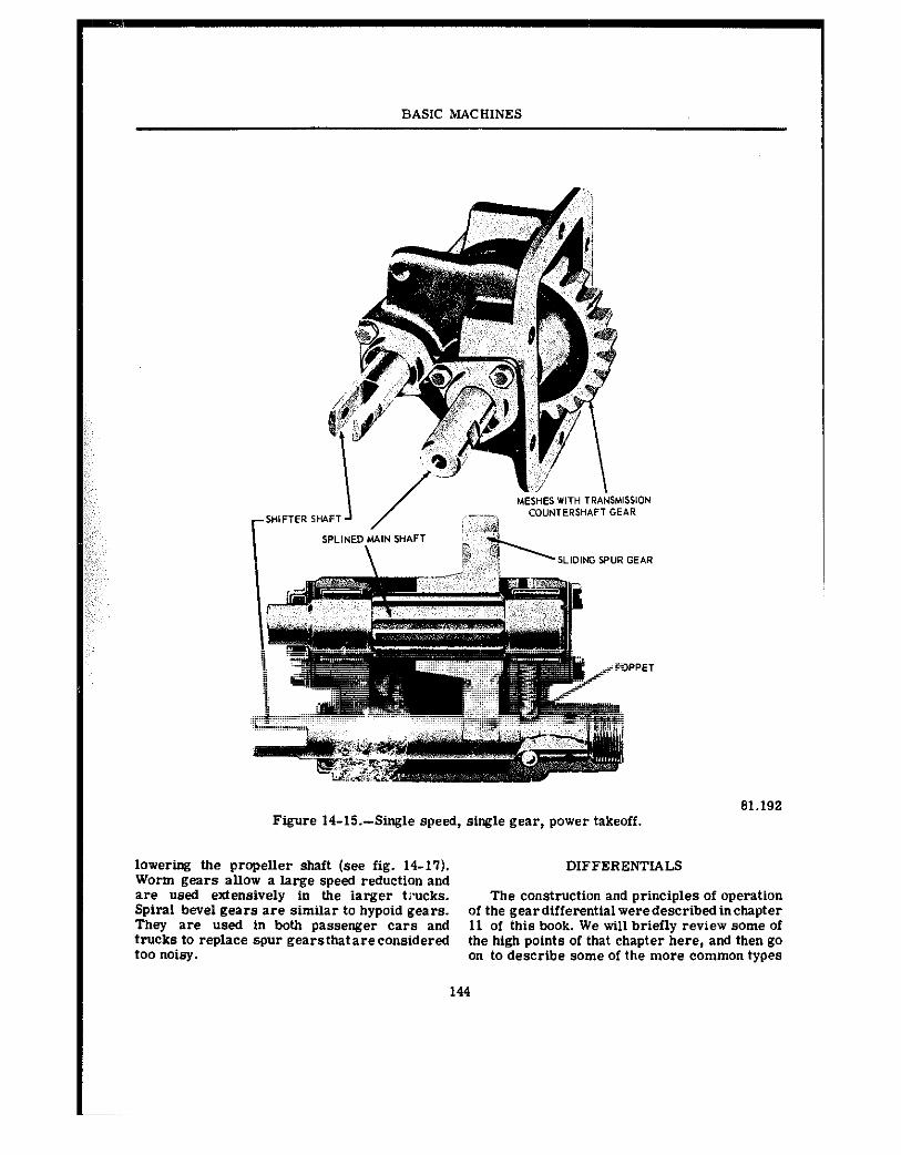
BASIC MACHINES
81.192 Figure 14-15.-Single speed, single gear, power takeoff.
lowering the propeller shaft (see fig. 14-17). DIFFERENTIALS Worm gears allow a large speed reduction and are used extensively in the iarger trucks. The construction and principles of operation Spiral bevel gears are similar to hypoid gears. of the geardifferentialweredescribedinchapter They are used in both passenger cars and 11 of this book. We will briefly review some of trucks to replace spur gears that are considered the high points of that chapter here, and then go too noisy. on to describe some of the more common types
144
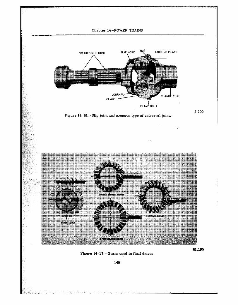
Chapter 14~POWER TRAINS
Figure 14-16.-Slip joint and common type of universal joint.:
81.195
FIgwe 14-17.-Gears used in final drives.
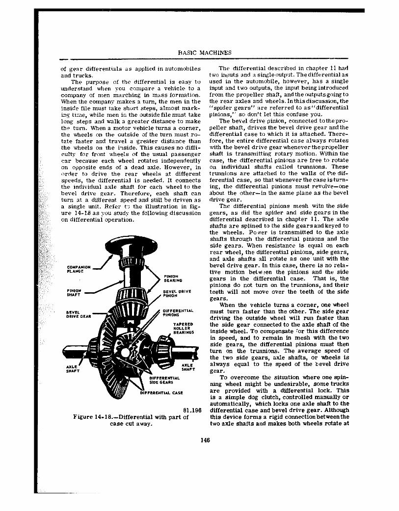
BASIC MACHINES
of gear differentials as applied in automobiles and trucks.
The purpose of the differeutial is easy to understaud when you compare a vehicle to a company of men mar&in% in mass formation. Wlen the company makes a turn, the men in the !nside file must take short steps, almost mark- in% tixe, wkile men in the outside file must take long steps and xvxlk a greater distance to make tk? tilrn. When a motor vehicle turns a corner, the wheels on the outside of the turn must ro- tate faster and travel a greater distance than the xvkeels on the i-side. This causes no diffi- culty for front wheels of the usual passenger car because each -Steel rotates independently on opposite ends of a dead axle. However, in order to drive tke rear wkeels at different speeds, the differential is needed. It connects the individual axle shaft for each wheel to the bevel drive gear. Therefore, each shaft can turn at a different speed and still be driven as a single unit. Refer t? the illustration in fig- ure 14-U as you study the following discussion on differential operation.
61.196 Figure 14-16.-Differential with part of
ease cut away.
The differential described in chapter 11 had two inputs and a singleoutput. Tkediffcrentialas used in the automobile, however, has a single input and two outputs, the input being introduced from the propeller shaft, and the outputsgoing to the rear axles and wheels. lntkis discussion, the “spider gears” are referred to as”differentin1 pinions,” so don’t let this confuse you.
The bevel drive pinion, connected totkepro- peller shaft, drives the bevel drive gear and the differential case to which it is attached. Tkere- fore, the entire differential case always rotates with the bevel drive gear whenever the propeller shaft is transmitting rotary motion. Within tine case, the differential pinions are free to rotate on individual shafts c&led trunnions. These trunnions are attached to the walls of the dif- ferential case, so that whenever the case is turn- ing, the differential pinions must revolve-one about the other-in the same plane as the bevel drive gear.
The differential pinions mesh witn the side gears, as did the spider and side gears in the differential descritued in chapter 11. The axle shafts are splined to the side gears and keyed to the wheels. Power is transmitted to the axle shafts through the differential pinions and the side gears. When resistance is equal on each rear wheel, the differential pinions, side gears, and axle shafts all rotate as one unit with the bevel drive gear. In this case, there is no rela- tive motion betwen the pinions and the side gears in the differential case. That is, the pinions do cot turn on the trunnions, and their teeth will not move over the teeth of the side gears.
When the vehicle turns a corner, one wheel must turn faster than the other. The side gear driving the outside wheel will run faster than the side gear connected to the axle shaft of the inside wheel. To compensate :or this difference In speed, and to remain in mesh with the two side gears, the differential pinions must then turn on the trunnions. The average speed of the two side gears, axle shafts, or tieeis is always equal to the speed of the bevel drive gear.
To overcome the siiuation where one spin- ning wheel might be undesirable, some trucks are provided -with a differential lock. This is a simple dog clutch, controlled manually or automatically, which locks one axle shaft to the differential case and bevel drive gear. Although this device forms a rigid connectionbetweenthe two axle shafts and makes both wheels rotate at
146
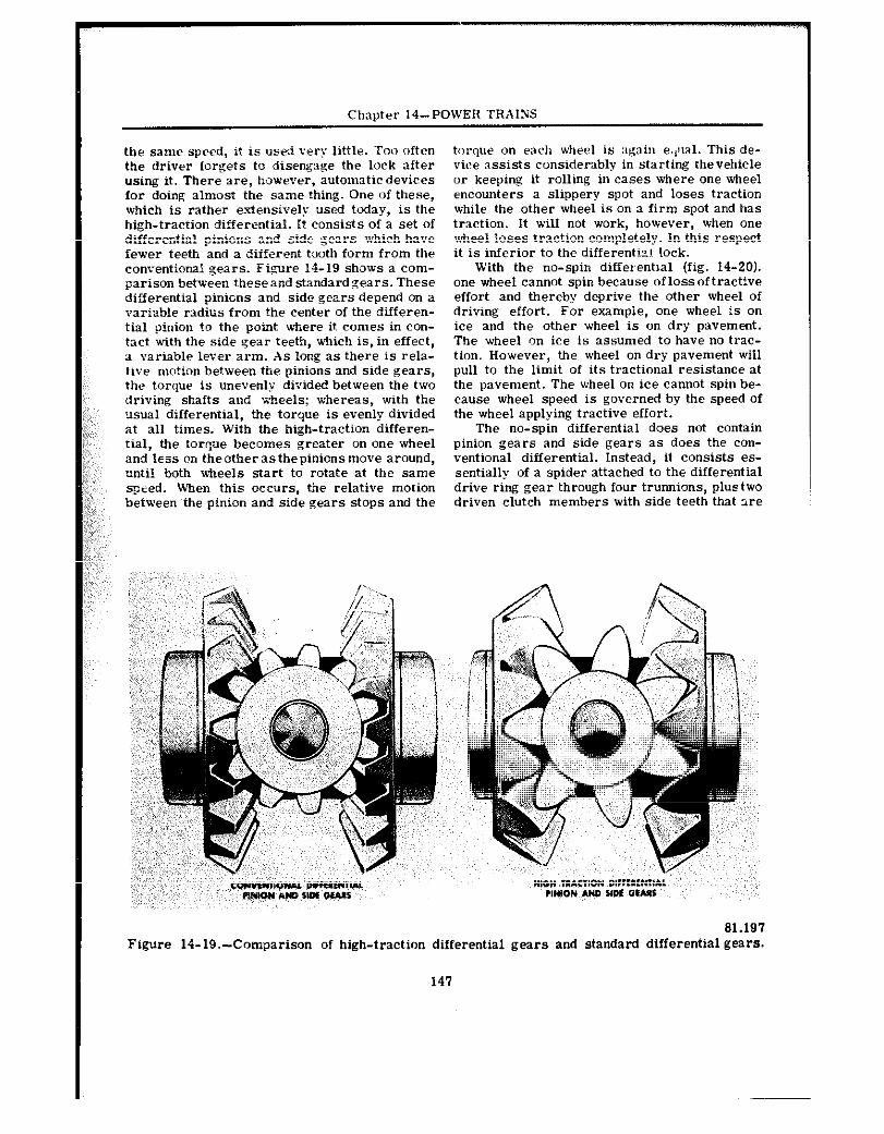
Chapter I$-POWER TRAINS
the same speed, it is used very little. Too often torque on each wkeel is :lg:lin e;,~ral. This de- the driver forgets to disenga&?e the lock after vice assists considerably in starting thevehicle using it. There we, however, automatic devices or keeping it rolling in cases where one wheel for doing almost the same thing. One of these, encounters a slippery spot and loses traction which is rather e.xtensive& used today, is the while the other wheel is on a firm spot and has high-traction differential. It consists of a set of traction. It will not work, however, when one differentia? pinions and side gears which hare wheel loses traction completely. In this respect fewer teeth and a different tooth form from the it is inferior to the differentill lock. conventional gears. Figure 14-19 shows a com- With the no-spin differential (fig. 14-20). parison between iheseandstandardgears. These one wheel cannot spin because oflossoftractive differential pinions and side gears depend on a effort and thereby deprive the other wheel of variable radiiis from the center of the differen- driving effort. For example, one wheel is on tial pinion to ike point ulwre it comes in con- ice and the other wheel is on dry pavement. tact with the side gear teeth, which is, in effect, The wheel on ice is assumed to have no trac- a variable lever arm. As long as there is rela- tion. However, the wheel on dry pavement will tive motion between the pinions and side gears, pull to the limit of its tractional resistance at tke torque is unerenlp divided between the two the pavement. The wheel on ice cannot spin be- driving shafts and wheels; wkereas, wiik the cause wheel speed is governed by the speed of usual differential, the torque is evenly divided the wheel applying tractive effort. at all times. Witb the high-traction differen- The no-spin differential does not contain tial, the torqe becomes greater on one wheel pinion gears and side gears as does the con- and less on tkeotkerastbepinionsmove around, ventional differential. Instead, it consists es- until both x&eels start to rotate at the same sentially of a spider attacked to the differential qtrd. WBen this occurs, the relative motion drive ring gear through four trunnions, plustwo between the pinion and side gears stops and the driven clutch members with side teeth that we
,,~,: ~,,,;:
81.191 Figure 14-19.~Comparison of high-traction differential gears and standard differential gears.
141
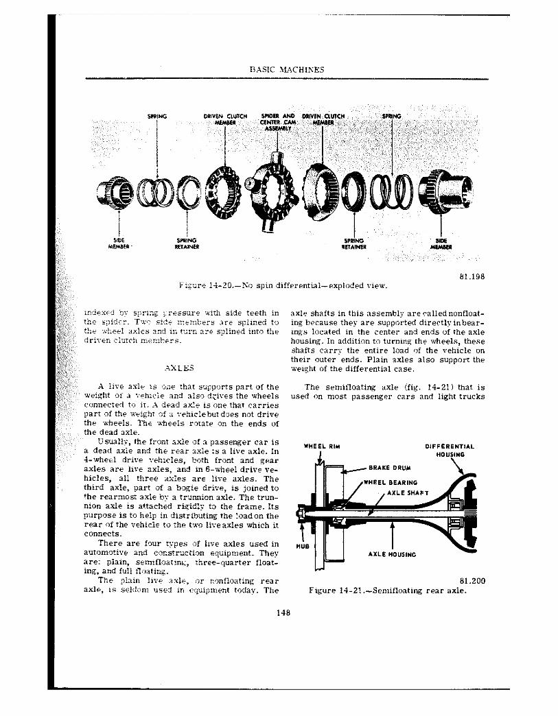
81.198 Figure 14:-?O.-X‘o spin differential-exploded view.
.AIXLES
A !ive as1.z is ,;.l@ that supports part of the weight oi a i-thicli and also d:ir@s the wheels connected to il. A dead axle is one that carries part of the weight of a r@hicl@butdoes not drive :h@ wheels. The xhheeis rotate on the ends of the dead axle.
Usually, the front axle of 3 passenger car is a dead axle and the rear i.xEe is a live axle. In &wheel drive rehncles, both front and gear axles are live axles, and in 6-wheel drive ve- hic!es, all three 2:.&s are liv@ axles. The ihird axle, part oi a bogie drive, is joined to the rearmost axle by 3 trur,?ion axle. The trun- nion axle is attached rioid& to the frame. Its purposr is to heip in distributing the ioadon the r@ar oi the vehicle to rhe i’x9 li~eaxles which it connects.
There afe four types sf In@ axles used in aufomot~~e and consnruction equipment. They are: plain, semifi;iatins, ihrte-quarter float- ing, and full :loatirq.
axle shafts in this assembly are called nonfloat- ing hecause they are supported directlyinbear- ings located in the center and ends of the axle housing. In addition to turning the wheels, these shafts carry the entire load If the vehicle on their outer ends. Plain axles also support the weight of the differential case.
The semifloating axle (fig. 14-21) that is used on most passenger cars and light trucks
81.200 Figure 14-2!.-Semiflonting rear axle.
148
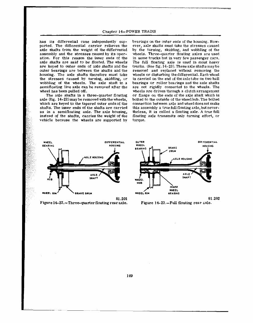
Chapter 14-POWER TRAINS
has its differential case independently sup- ported. The differential carrier relieves the axle shafts from the weight of the differential assembly and the stresses caused by its oper- ation. For this reason the inner ends of the axle shafts are said to be floated. The wheels are keyed to outer ends of axle shafts and the outer bearings are between the shafts and the housing. The axle shafts therefore must take the stresses caused by turning, skidding, or wobbling of the wheels. The axle shaft ir. a semifloating live axle can be removed after the wheel has been pulled off.
The axle shafts in a three-quarter floating axle (fig. 14-22)maybe removed withthe wheels, which are keyed to the tapered outer endsof the shafts. The inner ends of the shafts are carried as in a semifloating axle. The axle housing, instead of the shafts, carries the weight of the vehicle because the wheels are supported by
81.201 Figurel4-22.-Three-q4arterfloatingrearaxle.
bearings on the outer ends of the housing. How- ever, axle shafts must take the stresses caused by the turning, skidding, and wobbling of the wheels. Three-quarter floating axles are used in same trucks but in very few passenger cars. The full floating axle is used in most heavy trucks. (See fig. 14-23). Theseaxleshaftsmaybe removed and replaced without removing the wheels or disturbing thedifferential. Each wheel is carried on the end of theaxletube on two ball bearings or roller bearings and the axle shafts are not rigidly connected to the wheels. The wheels are driven through a clutcharrangement or flange on the ends of the axle shaft which is bolted to the outside of the wheel hub. The bolted connection between axle and wheeldoesnot make this assembly a truefullfloatingaxle,but never- theless, it is called a floating axle. A true full floating axle transmits only turning effort, or torque.
81.202 Figure 14-23.-Full floating rear txle.
149
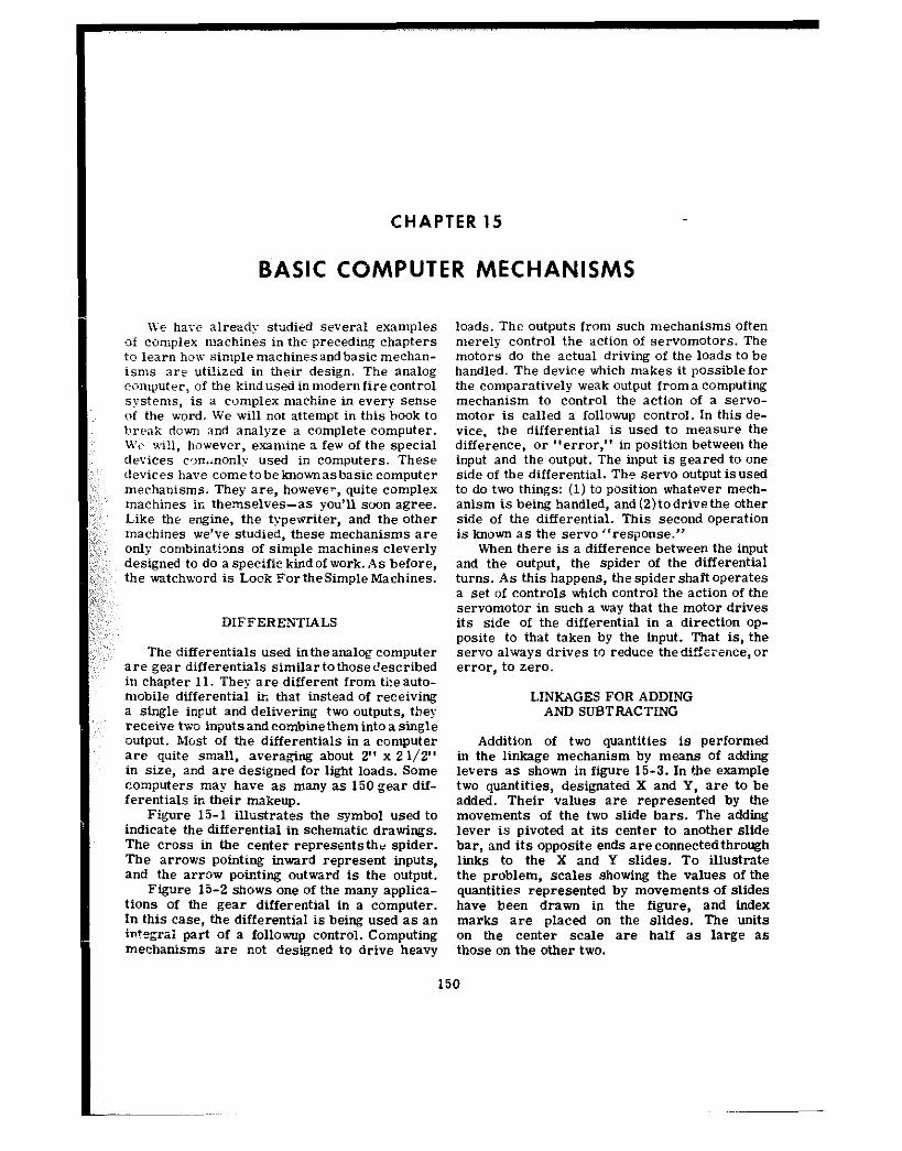
CHAPTER 15
BASIC COMPUTER MECHANISMS
We have alread? studied several examples of complex machines in the preceding chapters to learn lmn simple machines and basic mechan- isms are uti!ized in their design. The analog computer, of t!le kindused inmodernfire control systems, is a complex machine in every sense of the word. We will not attempt in this book to break down and analyze a complete computer. We will, however, exanline a few of the special devices ~o”.~nonly used in computers. These devices have cometobeknownasbasiccomputer mechanisms. They are, howevev, quite complex machines in themselves-as you’ll soon agree. Like the engine, the typewriter, and the other machines we’ve studied, these mechanisms are only combinations of simple machines cleverly designed to do a specific kind of work. As before, the watchword is Look For the Simple Machines.
DIfFERE?JTL4LS
The differentials used intheanalo~computer are gear differentials similartothosedescribed in chapter 11. They are different from theauto- mobile differential in that instead of receiving a single input and delivering two outputs, they receive two in~utsandcombinethemintoa single output. Most of the differentials in a computer are quite small, averaging about 2” x 21/2” in size, and are designed for light loads. Some computers may have as many as 150 gear dif- ferentials in their makeup.
Figure 15-l illustrates the symbol used to indicate the differential in schematic drawings. The cross in the center representsthe spider. The arrows pointing inward represent inputs, and the arrow pointing outward is the output.
Figure 15-2 shows one of the many appliea- tions of the gear differential in a computer. In this case, the differential is being used as a” i”?egxi part of a followup control. Computing mechanisms are not designed to drive heavy
150
loads. The outputs from such mechanisms often merely control the action of servomotors. The motors do the actual driving of the loads to be handled. The device which makes it possiblefor the comparatively weak output froma computing mechanism to control the action of a servo- motor is called a followup control. In this de- vice, the differential is used to measure the difference, or “error,” in position between the input and the output. The input is geared to one side of the differential. The servo output isused to do two things: (1) to position whatever mech- anism is being handled, and (2)todrivethe other side of the differential. This second operation is known as the servo “response.”
When there is a difference between the input and the output, the spider of the differential turns. As this happens, the spider shaft operates a set of controls which control the action of the servomotor in such a way that the motor drives its side of the differential in a direction op- posite to that taken by the input. That is, the servo always drives to reduce thedifference, or error, to zero.
LINKAGES FOR ADDING AND SUBTRACTING
Addition of two quantities is performed in the linkage mechanism by means of adding levers as shown in figure 15-3. In the example two quantities, designated X and Y, are to be added. Their values are represented by the movements of the two slide bars. The adding lever is pivoted at its center to another slide bar, and its opposite ends areconnectedthrough links to the X and Y slides. To illustrate the problem, scales showing the values of the quantities represented by movements of slides have been drawn in the figure, and index marks are placed on the slides. The units on the center scale are half as large as those on the other two.
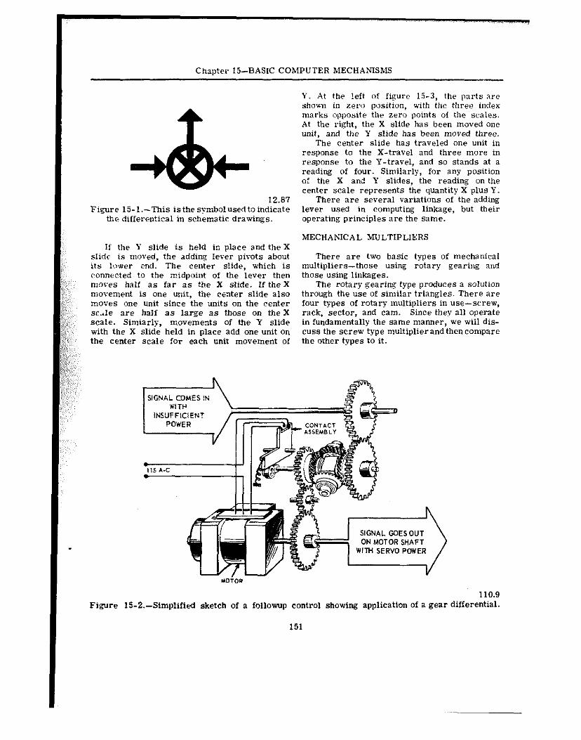
Chapter l&BASIC COMPUTER MECHANISMS -
12.81 Figure 15-l.-This isthe symbolused toindicate
the differentical in schematic drawings.
If the Y slide is held in place and the X slide is moved, the adding Iever pivots about its lower end. Tbe center slide, which is connected to the midpoint of the lever then moves half as far as the X slide. If the X movement is one unit, the center slide also moves one unit since the units on the center srik are half as large as those on theX scale. Simiarly, movements of the Y slide with the X slide held in place add one unit on the center scale for each unit movement of
Y. At the !eft of figure 15-3, the parts are shown in zero position, with the three index marks opposite the zero points of the scales. At the right, the X slide has been moved one unit, and the Y slide has been moved three.
The center slide has traveled one unit in response to the X-travel and three more in response to the Y-travel, and so stands at a reading of four. Similarly, for any position of the X and Y slides, the reading on the center scale represents the quantity X plus Y.
There are several variations of the adding lever used in computing linkage, but their operating principles are the same.
MECHANICAL MULTIPLIERS
There are two basic types of mechanical multipliers-those using rotary gearing and those using linkages.
The rotary gearing type produces a solution through the use of similar triangles. There are four types of rotary multipliers in use-screw, rack, sector, and cam. Since they all operate in fundamentally the same manner, we will dis- cuss the screw type multiplier and then compare the other types to it.
110.9 Figure 15-2.-Simplified sketch of a followup control showing application of a gear differential.
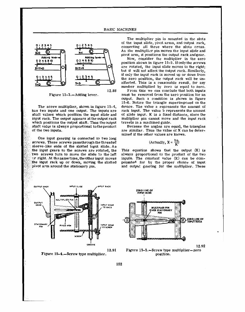
BASIC MACHINES
The multiplier pin is mounted in the slots
0,234s of the input slide, pivot arms, and output rack, connecting all three where the slots cross. As the multiplier pin moves the input slide and pivot arm, it positions the output rack andgear.
Now, consider the multiplier in the zero position shown in figure 15-5. Ifonlythe screws are rotated, the input slide moves to the right; but it will not affect the output rack. Similarly, if only the input rack is moved up or dew from the zero position, the output rack will be un- affected. This is a reasonable result, for any number multiplied by zero is equal to zero.
12.86 From this we can conclude that both inputs Figure Ii-3.-Adding lever. must be removed from the zero position for an
output. Such a condition is shown in figure 15-6. Notice the triangle superimposed on the
The screw multiplier, shown in figure 15-4, device. The value a represents the amount of has two inputs and one output. The inputs are rack input. The value h represents the amount shaft values which position the input slide and of slide input. K is a fixed distance, since the input rack. The output appears at the output rack multiplier pin cannot move and the input rack which positions the output shaft. Thus theoutput travels in a machined guide. shaft valqe is always proportional totheproduct Because the angles are equal, the triangles of the two inputs. are similar. Thus the value of X can be deter-
mined if the other values are known. One input gearing is connected to two long
screws. These screws passthroughthethreaded sleeve-like ends of the slotted input slide. As
(Actually, X = 2)
the input gears to the screws are rotated, the This equation shows that the output 00 is two screws turn to move the slide to the left always proportional to the product of the two cr right. At the same time, the other input moves inputs. The constant value (K) can be com- the input rack up or down, moving the slotted pensated for by the proper choice of input pivot a?m around the stationary pin. and output gearing for the multiplier. These
4
12.91 Figre 15-4.-Screw type multiplier.
12.92 Figwe 15-5.-Screw type multiplier-zero
position.
152
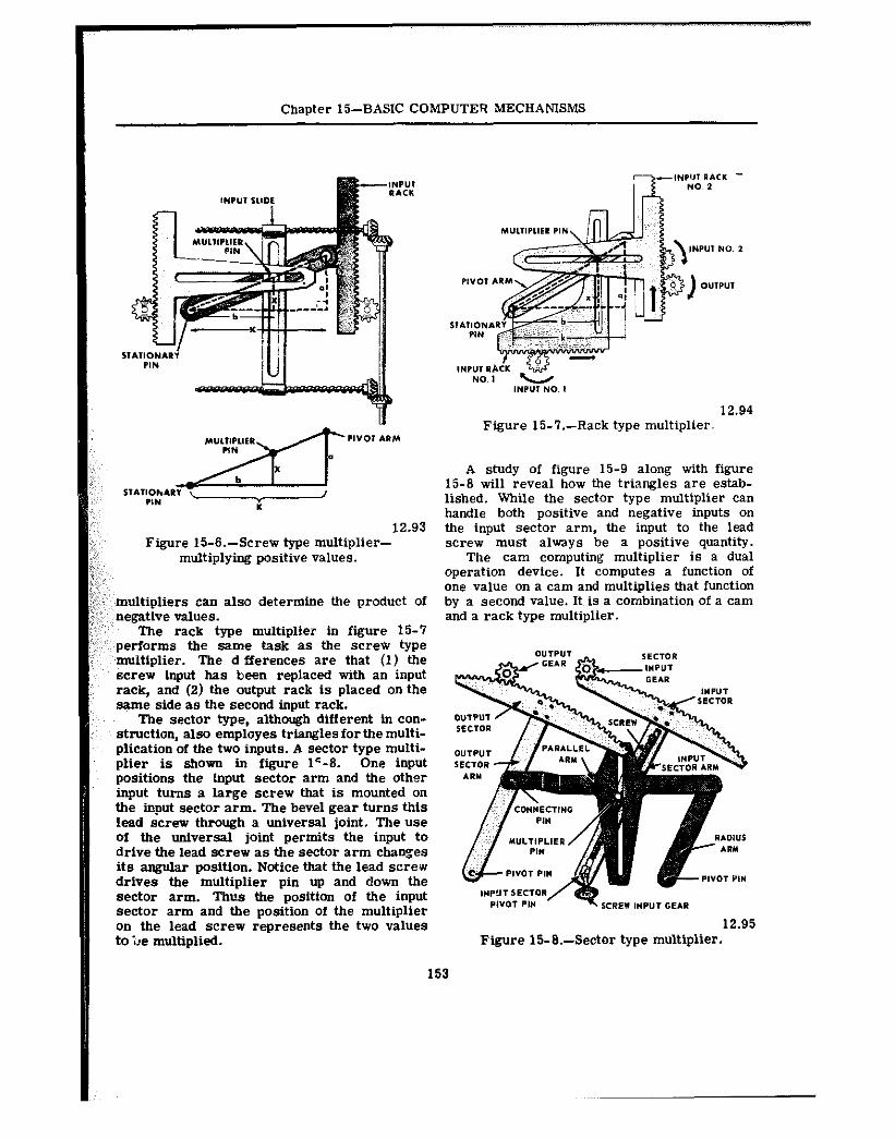
Chapter 15-BASIC COMPUTER MECHANISMS
12.93 Figure 15-S-Screw type multiplier-
multiplying positive values.
multipliers can also determine the product of negative values.
The rack type multiplier in figure 15-7 ‘,’ performs the same task as the scredr type
multiplier. The d fferences are that (1) the screw input has been replaced with an input rack, and (2) the output rack is placed on the same side as the second input rack.
The sector type, although different hi con- struction, also employes triangles forthemulti- plication of the two inputs. A sector type multi- plier is shown in figure l’-8. One input positions the input sector arm and the other input turns a large screw that is mounted on the input sector arm. The bevel gear turns this lead screw through a universal joint. The use of fhe universal joint permits the input to drive the lead screw as the sector arm changes its angular position. Notice that the lead screw drives the multiplier pin up and down the sector arm. Thus the position of the input sector arm and the position of the multiplier on the lead screw represents the two values to l,e multiplied.
INP”, NO. 1 12.94
Figure 15-T.--Rack type multiplier.
A study of figure 15-9 along with figure 15-S will reveal how the triangles are estab- lished. While the sector type multiplier can handle both positive and negative inputs on the input sector arm, the input to the lead screw must always be a positive quantity.
The cam computing multiplier is a dual operation device. It computes a function of one value on a cam and multiplies that function by a second value. Its is a combination of a cam and a rack type multiplier.
12.95 Figure 15-E.-Sector type multiplier.
153
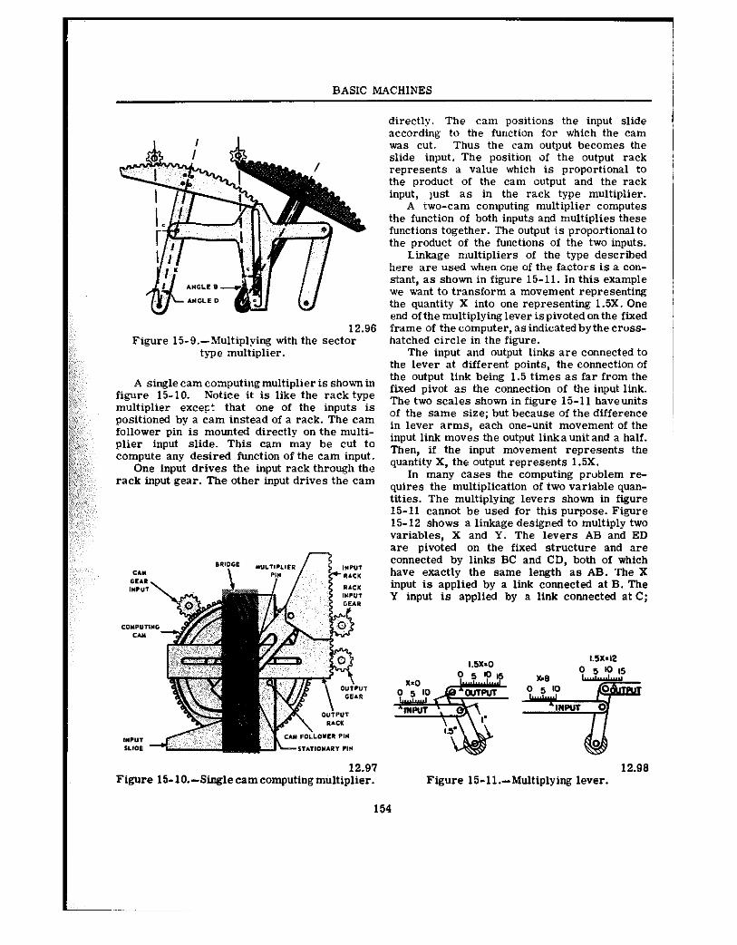
BASIC MACHINES
12.96 Figure 15-9.-Multiplying with the sector
type multiplier.
A single cam computing multiplier is shown in figure 15-10. Notice it is like the rack type multiplier except that one of the inputs is positioned by a cam instead of a rack. The cam follower pin is mounted directly on the multi- plier input slide. This cam may be cut to compute any desired function of the cam input.
One input drives the input rack through the rack input gear. The other input drives the cam
12.91 Figure 15-10.-Singlecamcomputingm”ltiplier.
154
directly. The cam positions the input slide according to the function for which the cam was cut. Thus the cam output becomes the slide input. The position of the output rack represents a value which is proportional to the product of the cam output and the rack input, lust as in the rack type multiplier.
A rwo-cam computing multiplier computes the function of both inputs and multiplies these functions together. The output is proportionalto the product of the functions of the two inputs.
Linkage multipliers of the type described here are used when one of the factors is a con- stant, as shown in figure 15-11. In this example we want to transform a movement representing the quantity X into one representing 1.5X. One end of the multiplying lever is pivoted on the fixed frame of the computer, as indicated bythe cross- hatched circle in the figure.
The input and output links are connected to the lever at different points, the connection of the output link being 1.5 times as far from the fixed pivot as the connection of the input link. The two scales shown in figure 15-11 haveunits of the same size; but because of the difference in lever arms, each one-unit movement of the input link moves the output link a unit and a half. Then, if the input movement represents the quantity X, the output represents 1.5X.
In many cases the computing prublem re- quires the multipiication of two variable quan- tities. The multiplying levers shown in figure 15-11 cannot be used for this purpose. Figure 15-12 shows a linkage designed to multiply two variables, X and Y. The levers AB and ED are pivoted on the fixed structure and are connected by links BC and CD, both of which have exactly the same length as AB. The X input is applied by a link connected at B. The Y input is applied by a link connected at C;
12.98 Figure 15-ll.-Multiplying lever.
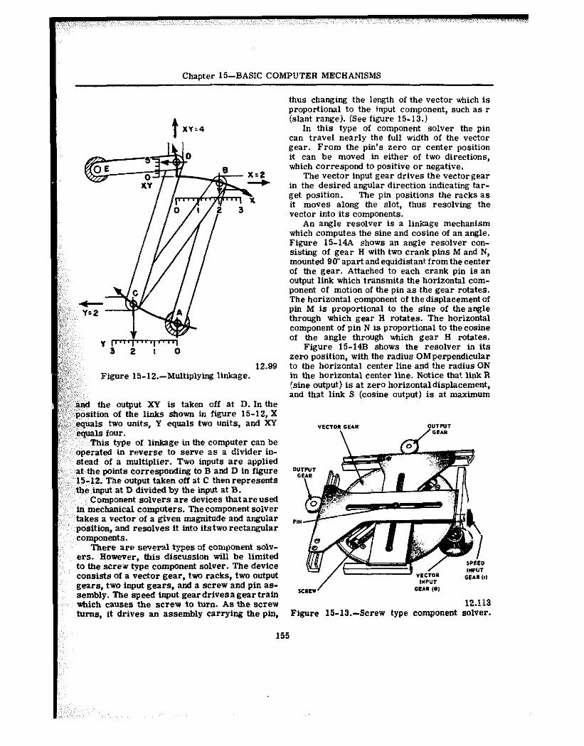
Chapter 15-BASIC COMPUTER MECHANISMS
12.99 Figure 15-12.-Multiplying linkage.
~f@and the output XY is taken off at D. In the ;,f;:::position of the link-s shown in figure 15-12, X ;:,‘:equals two units, Y equals two units, and XY
equals four. This type of linkage in the computer can be
operated in reverse to serve as a divider in- stead of a multiplier. Two inputs are applied at the points corresponding to B and D in figure 15-12. The output taken off at C thenrepresents the input at D divided by the input at B.
Component solvers are devices that are used ,in mechanical computers. Thecomponent solver takes a vector of a give” magnitude and angular
components.
I
position, and resolves it into its two rectangular
There are sever-l *es of eomponeni solv- era. However. this discussion wtll be limited to the screw type component solver. The device consists of a vector gear, two racks, two output gears, two input gears, and a screw and pin as- sembly. The speed input geardrtvesagear train which causes the screw to turn. As the screw
I turns, it drives an assembly carrying the pin,
155
thus changing the length of the vector which is proportional to the input component, such as r (slant range). (See figure 15-13.)
In this type of component solver the pin can travel nearly the full width of the vector gear. From the pin’s zero or center position it can be moved in either of two directions, which correspond to positive or negative.
The vector input gear drives the vectorgear in the desired angular direction indicating tar- get position. The pin positions the racks as it moves along the slot, thus resolving the vector into its components.
An angle resolver is a linkage mechanism which computes the sine and cosine of an angle. Figure 1%14A shows an angle resolver con- sisting of gear Ii with two crank pins M and N, mounted 90” apart and equidistant from the center of the gear. Attached to each crank pin is an output link which transmits the horizontal com- ponent of motion of the pin as the gear rotates. The horizontal component of the displacement of pi” M is proportional to the sine of the angle through which gear H rotates. The horizontal component of pin N is proportional to the cosine of the angle through which gear Ii rotates.
Figure 15-14B shows the resolver in its zero position, with the radius OMperpendicular to the horizontal center line and the radius ON in the horizontal center line. Notice that link R (sine output) is at zero horizontaldisplacement, and that link S (cosine output) is at maximum
0” G
Figure 15-13.-Screw type component solver.
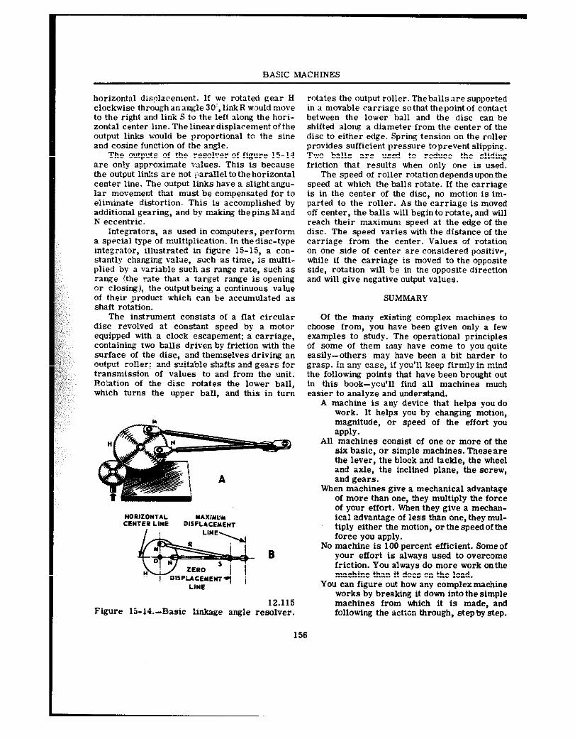
BASIC MACHINES
horizontal dis@cement. If we rotated gear H clockwise through a” anfile 30’. link R would move to the right and link S to the left along the hori- zontal center line. The linear displacement of the output links would be proportional to the sine and cosine function of the angle.
The outputs of the resolver of figure 15-14 are only approximate ralues. This is because the output 1i”ks are not parallel to the horizontal center line. The output lb&s have a slight angu- lar movement that must be compensated for to eliminate distortion. This is accomplished by additional gearing, and by maldng the pins M and N eccentric.
:ntegrators, as used in computers, perform a special type of multiplication. I” thedisc-type integrator, illustrated in figure 15-15, a con- stantly changing value, such as time, is multi- plied by a variable such as range rate, such as range (the rate that a target range is opening or closing), the outputbeing a continuous value of their ,product which can be accumulated as shaft rotation.
The instrument consists of a flat circular disc revolved at constant speed by a motor equipped with a clock escapement; a carriage, containing two balls driven by friction with the surface of the disc, and themselves driving an output roller; and suitable shafts and gears for transmission of values to and from the unit. P.&&ion of the disc rotates the lower ball, which turns the upper ball, and this in turn
- B
12.115 Figure 15-14.--Basic Wkage angle resolver.
156
rotates the output roller. Theballs are supported in a movable carriage so that the point of contact between the lower ball and the disc can be shifted along a diameter from the center of the disc to eitlner edge. Spring tension on the roller provides sufficient pressure to prevent slipping. Two balls are used to reduce the sliding friction that results when only one is used.
The speed of roller rotation depends upon the speed at which the balls rotate. If the carriage is in the center of the disc, no motion is im- parted to the roller. As the carriage is moved off center, the balls will begin to rotate, and till reach their maximum speed at the edge of the disc. The speed varies with the distance of the carriage from the center. Values of rotation on one side of center are considered positive, while if the carriage is moved to the opposite side, rotation will be in the opposite direction and will give negative output values.
SUMMARY
Of the many existing complex machines to choose from, you have been given only a few examples to study. The operational principles of .?.ome of them may have come to you quite easily-others may have been a bit harder to grasp. In any case, if you’ll keep firmly in mind the following points that have been brought out in this book-you’ll find all machines much easier to analyze and understand.
A machine is any device that helps you do work. It helps you by changing motion, magnitude, or speed of the effort you apply.
All machines consist of one oi- more of the six basic, or simple machines. Thoseare the lever, the block and tackle, the wheel and axle, the inclined plane, the screw, and gears.
When machines give a mechanical advantage of more than one, they multiply the force of your effort. When they give a mechan- ical advantage of less than one, they mul- tiply either the motion, oi- the speed of the force you apply.
No machine is 100 percent efficient. Someof your effort is always used to overe~me friction. You always do more work onthe machine than it does on the load.
You can figure out how any complexmachine works by breaking it down into the simple machines from which it is made, and following the action through, stepby step.
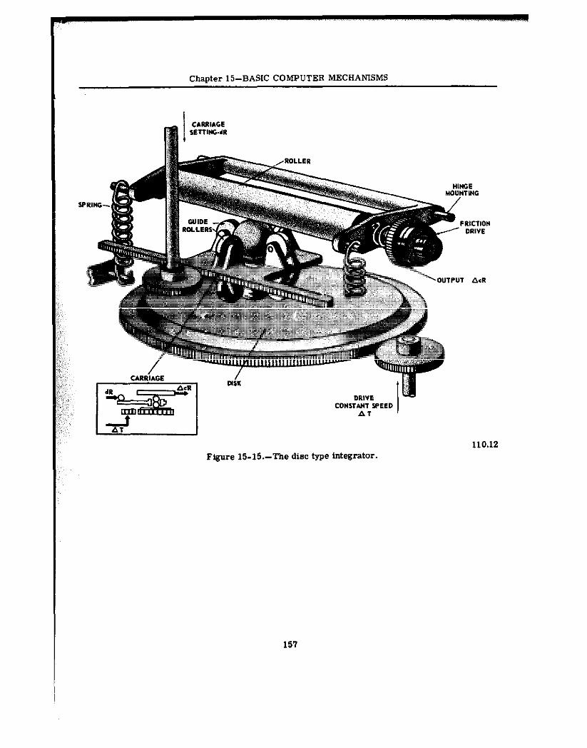
chanter i5-~~sic COMPUTER MECHANISMS
Figure 15-N.-The disc type integrator.
157
Accumulator, 67 Anchor winch, 36, 38 Automobile valve gear, 36 Axles used in power trains, 148, 149
Balancing moments of force, 18 Ballast tank, 67, 66 Ball bearings, 71, 73 Barometer, 54-57 Bearings, 69-73 Bendix-Weiss universal joint, 79 Bevel gear, 31 Bevel gear differential, ‘75 Block and tackle, 10-15, 41
applications afloat and ashore, 13 chain hoist, 15 flaghoist, 10 gun tackle, 11 luff tackle, 11 hlff upon luff, 13, 14 mechanical advantage, 10, 15 runner, 10 yard and stay tackle, 13
Bollrdo” gage, 53 Brakes, 28, 63
friction, 28 hydraulic, 63
Breech, l&inch gun, I
Cams, 65 Cam and cam followers, 60-82 Cam-driven valve. 36 Cam shaft, 36
of a 4-stroke cycle engine, 127 Capstao bar, 17, It? Chaii h@ist, 15 mail stoqer, 8 Clockwisr moments of force, 19 Clutches, 62, 86, 130-133
power ‘rain, 130-133 ?omhustion engines, 106-129
basic strokes, 108 classification of, 113 construction of, 115-129
auxiliary assemblies, 129 connecting rods, 123 crankcase, 117
INDEX
crankshaft, 124 cylinder head, 117 engine cylinder block, 115 engine head, 126 exhaust manifold, 118 gaskets, 119 intake manifold, 118 moving parts, 119-129 piston assembly, 120 stationary parts, 115-119 timing gears, 128 valves and valve mechanisms, 126-128 vibration damper, 125
cycles, 109-112 development of power, 106 diesel engines, 114 gasoline engines, 114 multiple-cylinder engines, 112 one-cylinder engine, 106-112
Complex machines, 87-105 computer mechanisms, 150-151 fuel-oil-hatch cover, 87 porthole closer-blanket puller-upper, 67, 88 typewriter, 89-105 watertight door, 88
Computer mechanisms, 150-157 differentials, 150-151 linkages for adding and subtracting, 150-156
adding lever, 152 angle resolver, 156 component solver, 155 integrators, 156 multipliers, 151-156 multiplying linkage, 155 screw type multipliers, 152
‘Constant mesh transmission, 136 Counterclockwise moments of force, 19 Couple, 20 Couplings, 78-84 Crane, electric, 7 Curved lever arms, 5 Cylinders used in power trains, 131
Deep-sea diver, 60 Depth charge, 59
158
INDEX
Diesel engine, 106, 114 Differentials, gear, 144-148 Dogs, 7 Drill 9 press,
Electric 7 crane, External combustion engine, 106, 107 External mesh gears, 35
Final drives, 142 Flagboist, 10 Fluids, pressure exerted by, 52 Force and pressure, 50-57
force, measurement of, 50 pressure, measurement Of, 50-56
barometers, 54-56 exerted by fluids, 52
c gages, 53 manometer, 56 scales, 50, 51
Four-speed truck transmission, 133 Friction, 40, 42-46 Friction brake, 28 Fuel-oii-hatch 87 cover, Fulcrum, 17, 19-21
Gages used to measure pressure, 53 Gangplank, 24 Gasoline engine, 106, 114
: Gear differential, 74-?8, 144-148 used in automobiles and trucks, 144-148
Gears, 30-38
anchor winch, 36. 38 automobile valve gear, 36 cam-driven valve, 36 cam shaft, 36 changing speed, 34 external mesh g%ws, 35 idler gear, 35 internal gear, 31 magntfylng force with, 35 pinion gear, 30 rack and pinion as a steering
mechanism, 37 spur g-, 30 types Of, 30-34 vmrm gears, 32
Gear trains, 126 Gun tackle, 11
Helical gears, 30 Herringbone gears, 31 Iiooke joint, 79 Horsepower, 46-46
Hydraulic machines, 62-68 advantages of, 63 brakes, 63 liquids in motion, 62 Pascal’s law, 62 press, 64 steering with, 65 used on submarines, 66
Hydrauiic valve lifter, 127 Iiydrostaoc machines, 58-61
Idler gear, 36 Inclined plane, 23-26
applications aflat and ashore, 24 barrel role, 23 gangplank, 24 in spiral form, 26 ramp, 23 wedge, 23
Internal combustion engines, 106-129 basic strokes, 108 classification of, 113 construction of, 115-129
auxiliary assemblies, 129 connecting rods, 123 crankcase, 117 crankshaft, 124 cylinder head, 117 engine cylinder block, 115 engine head, 126 exhaust manifold, 118 gaskets, 119 intake manifold, 118 moving parts, 119-12s piston assembly, 120 stationary parts, 115-119 timing gears, 128 valves and valve mechanisms, 126-126 vibration damper, 125
Internal year, 31
Jack, 41 Jack screw, 26, 27
Levers, 1-9 chain stopper, 8 classes of, 2 curved lever arm, 5 dogs, 7 drill press, 9 electric crane, 7 oars, 2 pelican hook, 6 wrecking bar, 7
159
BASIC MACHINES
Linkages, 78 Luff tackle, 11
Machine elements and basic mechanisms, 69-86
basic mechanisms, 74 bearings, 69-73
ball bearings, 73 cams, 80-82, 85
and cam followers, 80-82 clutches, 82, 86 couplings, 78-84 gear differential, 74-78 linkages, 78 radial-thrust roller bearing, 73 springs, 71-74 types Of, 74 universal joints, 79-81
Manometer, 56
Micrometer, 27 Moment of force, 17, 20 Multiple-cylinder engines, 112
oars. 2 Oldbarn coupling, 78, 80 One-cylinder engine, 106
Pelican hook, 8 Pinion gear, 30 Pointer’s handwheel, 21 Power, 46-57
calculation of, 46-48 horsepower, 46 motor, 48
Prony brake, 48 Power takeoffs, 141 POW?F tFGlS, i30-149
axles, 146, 149 clutch, 130-133 differentials, 144-148 final drives, 142-144 joints, 142,145 Pmpdler shaft assemblies, 142 transfer cases, 140-142 transmission, 133-139
Pressure and the deep sea diver. 60
PNSSure, measurement oi, 50-56 balances, 50. 52 barometers. 64-56 ex&ed by fluids, 52 was, 53 manometer, 56 scales, 50, 51
Prony brake, 46
Quadrant davit, 29
Rack and pinion, 37 Radial-thrust roller bearing, 71, 73 Ramp, 23 Rigger’s vise, 28 Roller bearing, 71, 73 Roller bitt, 43 Runner, 10
Scales, 50, 51 Sehrader gage, 53 Screw applications, 26-29
friction brake, 28 inclinrd plane in spiral form, 26 jack screw, 26, 27 mechanical advantage of, 29 micrometer, 26 quadrant davit, 29 rigger’s vise, 28 turnbuckle, 28
Sleeve coupling, 78 Spider gears, 76 Spiral bevel gears, 144 Springs, 71-74 Spur gears, 30 Steam engine, 106 Synchromesh clutch, 138 Synchromesh transmission, 136
Timing gears in engines, 128 Torpedo, 60 Torque, 17, 21, 22
wrench, 21 Transfer cases, 140-142 Truck transmission, 133 Turnbuckle, 28 ‘Typewriter, 89-105
backspace, 96 bell ringer, 102 construction and operation, SO escapement, 92 external parts, 89 line lock, 102 line space, 103 pinion stop slide, 103-105 ribbon drive, 93-96 shift, 99, 101, 102 ~Labulator, 96-99 type bar, 93
Universal joints, 79-81
Valve lifters, 127 Valves and valve mechanisms, engine, 126-126
160
INDEX
Watertight door, 68 Wedge, 23 Wheel and axle, 16-25
balanctng moments of force, 18 capstan bar, 17, 16 clockwise moments of force, 19 counterclockwise moments of
force, 19 couple, 20 fulcrum, 17, 19, 20. 21 mechanical advantage, 16 pointer’s landwheel, 21 rotation, 17
torque, 17, 21, 22 wrench, 21
Work, friction, and efficiency, 39-45 block and tackle, 41 friction, 42-45 jack, 41 measurement of, 39-41 roller bitt, 43
Worm and worm wheel, 32 Worm gear, 32 Wrecking bar, 7
Yard and stay tackle, 13
161
BASIC MACHINES AND HOWTHEWORK
BUREAU OF NAVAL PERSONNEL
Covering thoroughly basic theory. ranging from the lever and inclined plane up through basic computer mechanisms, this extraordinarily clear book leaves nothing to be desired in its presentation. Nothing more than the most elementary mathematics is required to follow it.
Beginning with the simplest of machines-the lever--the course pro- ceeds with the discussion of the block and tackle (pulleys and hoists), the wheel and axle, the ioclined plane and the wedge, the screw. and different types of gears (simple. spur, bevel. herringbone, spiral. worm, etc.). A chapter on the concept of work discusses the measurement of work. friction. and efbciency: this is followed by investigations of power, force sod pressure, explaining the uses of scales, balances, gauges and barometers. The fundamentals of hydrostatic and hydraulic ma- chines (such as the hydraulic braking system and the hydraulic press) are discussed in detail. The remaining chapters cover nwhine ele- ments (bearings and springs), basic mechanisms (gear differential, couplings. cam and cam followers, clutches), l-omplex machines (water- tight door, typewriter), the interoal combustion engine (its components and how it works), power trains (including explanations of various transmission systems-synchromesh, auxiliary, etc.). and basic computer mechanisms (linkages, multipliers, integrators, etc.).
Every concept is clearly defined and the discussions always build easily from elementary theory to particular applications that are familiar to anyone with the slightest ittterest in mechanics. Important concepts, machine cornportents and techniques are clearly illustrated ill more than 200 diagrams and drawings. cross-sections that reveal inner work- ings-all of these he+ to clarify eve11 further an already cleat atld well-organixd presentation. .Uthough it was originally designed for use in U.S. Naval Training Schools. this book can be used to great advantage as a basic text in mechanical engineering in standard techni- ~l~~ods, ar.d it will be immensely valuable evm to the layman who
doires a basic knowledge of machines.
Uoabtidged republication of Nary Traioing Course NavPers 16624-A (1965). 204 figures. Preface. Index: viii + 161~~. 6% x 9%.
2 I 709.4 Paperbound
A DOVER EDITION DESIGNED FOR YEARS OF USE! We have made every effort to make this the best hook possible. Our paper is opaque, with minimal show-through: it will not discolor or become brittle with age. Pages are sewn in signatures, in the method traditionally used for the best books, and will not drop out, as often happens with paperbacks held together with glue. Books open flat for easy reference. The binding will not crack or split. This is a pmanent book.