basic info regarding making a rc aeroplane
TRANSCRIPT

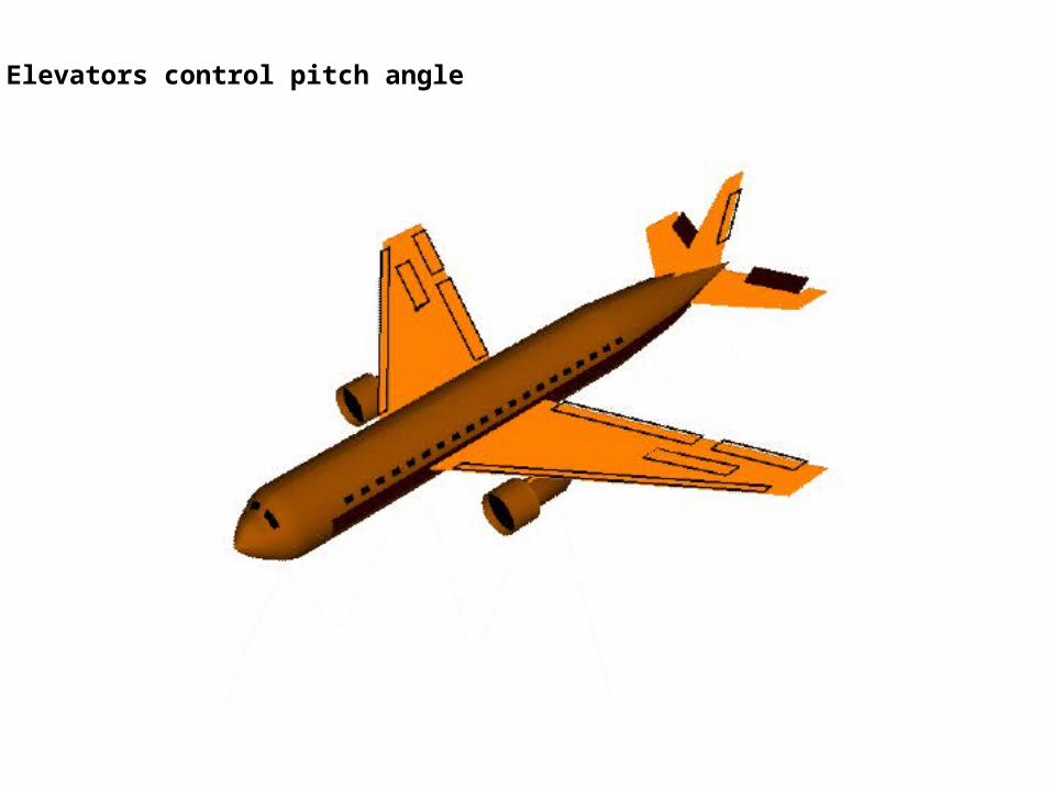
Elevators control pitch angle

Ailerons control roll angle
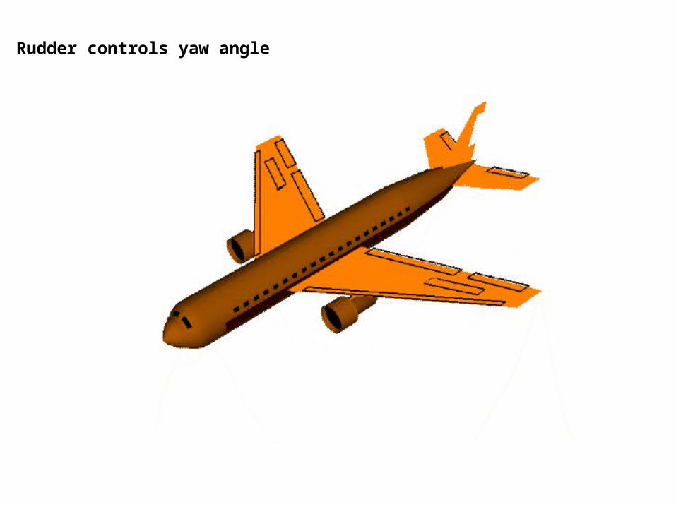
Rudder controls yaw angle
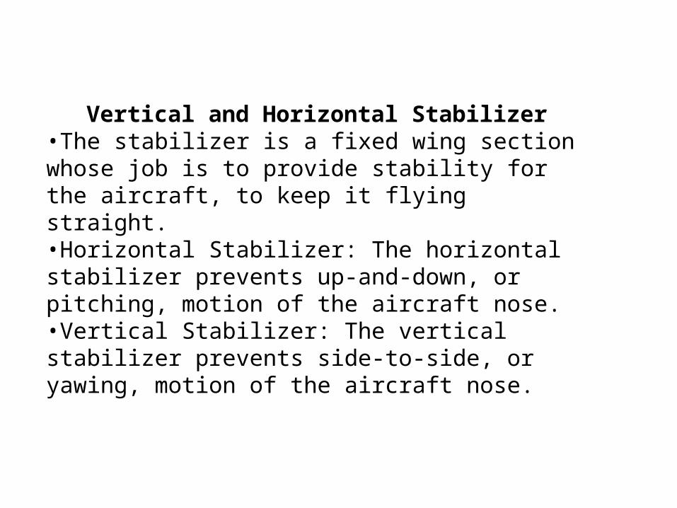
Vertical and Horizontal Stabilizer•The stabilizer is a fixed wing section whose job is to provide stability for the aircraft, to keep it flying straight. •Horizontal Stabilizer: The horizontal stabilizer prevents up-and-down, or pitching, motion of the aircraft nose.•Vertical Stabilizer: The vertical stabilizer prevents side-to-side, or yawing, motion of the aircraft nose.
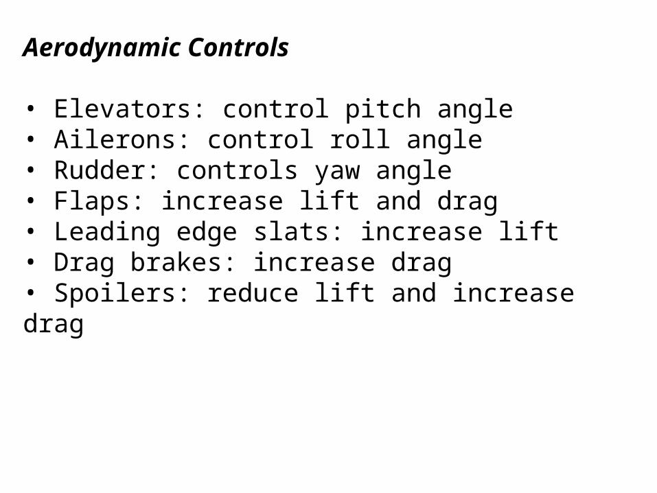
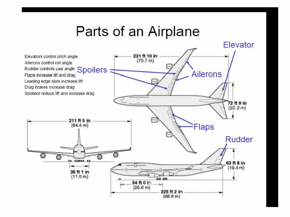
Aerodynamic Controls
• Elevators: control pitch angle• Ailerons: control roll angle• Rudder: controls yaw angle• Flaps: increase lift and drag• Leading edge slats: increase lift• Drag brakes: increase drag• Spoilers: reduce lift and increase drag
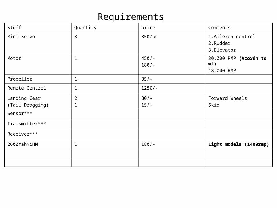
RequirementsStuff Quantity price Comments
Mini Servo 3 350/pc 1.Aileron control2.Rudder3.Elevator
Motor 1 450/-180/-
30,000 RMP (Acordn to wt)18,000 RMP
Propeller 1 35/-
Remote Control 1 1250/-
Landing Gear(Tail Dragging)
21
30/-15/-
Forward WheelsSkid
Sensor***
Transmitter***
Receiver***
2600mahNiHM 1 180/- Light models (1400rmp)

Styrofoam Usage
Similar to thermoCole, though smaller grain size.
Easier and faster to work on compared to balsa.
Can we wire cut to get the wing in one piece.
Needs proper strengthening by use of balsa and tape.
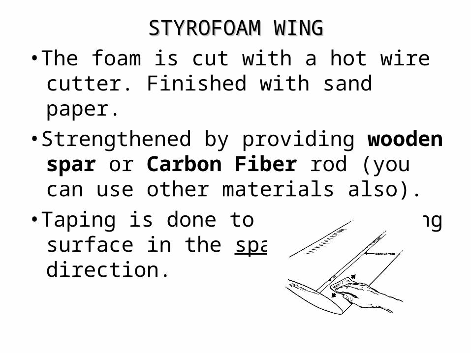
STYROFOAM WINGSTYROFOAM WING•The foam is cut with a hot wire cutter.
Finished with sand paper. •Strengthened by providing wooden spar or
Carbon Fiber rod (you can use other materials also).
•Taping is done to the whole wing surface in the span wise direction.


Aspect Ratio• it’s the ratio of wings length to its breadth• Wing span^2 / area of planform
Wing Span Plan Form
The distance betweenOne tip of the wing to Other end.
Wing planform is The silhouette of The wing when viewedFrom above

High AR means ??? •narrow wing, •Leading to less drag•helps in stability at low speeds•Low roll
Calculating Area of Planform???elevator and rudder their area too is to be included in the area
of the tail and vertical stabilizer respectively
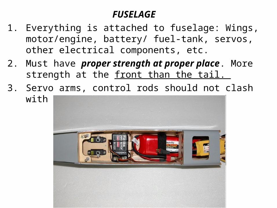
FUSELAGE1. Everything is attached to fuselage: Wings, motor/engine,
battery/ fuel-tank, servos, other electrical components, etc.
2. Must have proper strength at proper place. More strength at the front than the tail.
3. Servo arms, control rods should not clash with each other.

4 Should have proper space for the servos,5 battery receiver, esc, etc.
Fuselage lenght – 70-75 % of wing span.

MonoWing
High Wing Configuration• Shorter Landing Distance• Greater Stability at lower speeds
Moderate Tapered Wings•Good Stall characteristics•Straight Edge•Wings narrow towards tip
Wing Sweep –StraightWing is right angled to lineOf flight•Common for low speed
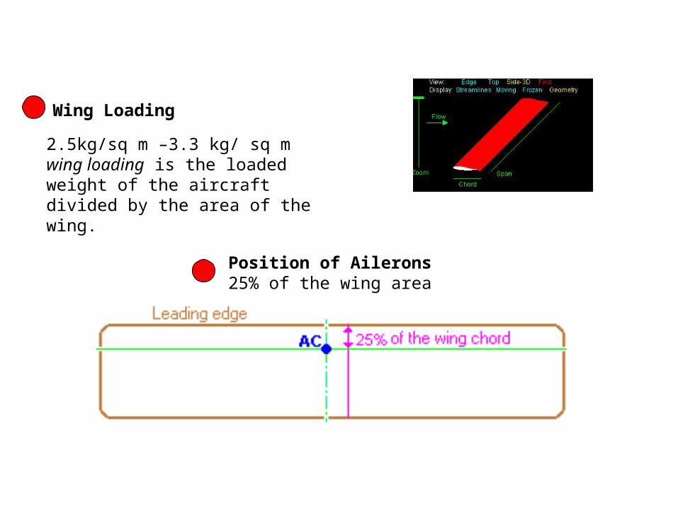
2.5kg/sq m –3.3 kg/ sq mwing loading is the loaded weight of the aircraft divided by the area of the wing.
Wing Loading
Position of Ailerons25% of the wing area
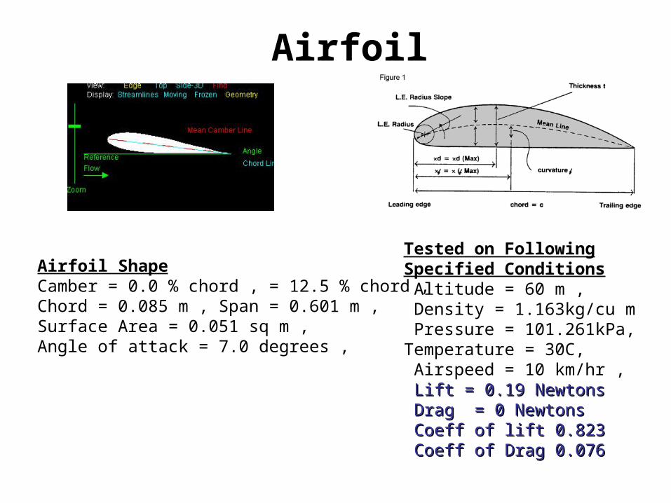
Airfoil
Airfoil Shape Camber = 0.0 % chord , = 12.5 % chord , Chord = 0.085 m , Span = 0.601 m , Surface Area = 0.051 sq m , Angle of attack = 7.0 degrees ,
Tested on FollowingSpecified Conditions Altitude = 60 m , Density = 1.163kg/cu m Pressure = 101.261kPa, Temperature = 30C, Airspeed = 10 km/hr , Lift = 0.19 NewtonsLift = 0.19 Newtons Drag = 0 NewtonsDrag = 0 Newtons Coeff of lift 0.823Coeff of lift 0.823 Coeff of Drag 0.076Coeff of Drag 0.076

SERVO

1. These are responsible for controls of aero models. 2. The control surfaces –ailerons, elevators, engine
throttle and rudders are connected to the servos using push rods .
3. All servos are connected to receiver. 4. Rotation of servos(torque) on receiving signal from
transmitter causes the movements of control parts.5. Defined by the torque they provide.
Stabilizers
The edges of the aileron were rounded to minimize drag effect.Vertical stabilizer 50% of HS
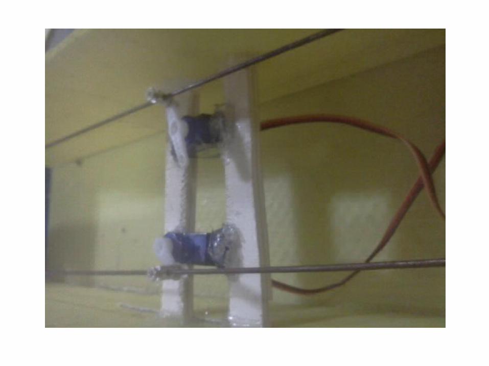
Engine
1. Engine mount is first fixed to the front of fuselage using nuts and bolts.2. Engine is attached to the mount.
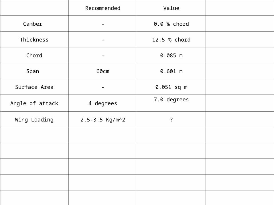
Recommended Value
Camber - 0.0 % chord
Thickness - 12.5 % chord
Chord - 0.085 m
Span 60cm 0.601 m
Surface Area - 0.051 sq m
Angle of attack 4 degrees7.0 degrees
Wing Loading 2.5-3.5 Kg/m^2 ?
Propellers
• Have diameter and pitch usually written in the form Diameter X pitch. D X P
• Pitch is the distance moved by the propeller in one revolution under ideal conditions.
• High pitch propeller generally provides more speed than a low one.
• Propellers can be double or triple blade. • Distance moved by an ideal propeller = pitch *
RPM

Motor
kv rating: It is the revolutions/volt. For ex: 1000 kv will give 1000 rpm at one volt. So if the voltage of battery is 12 V then the RPM is 1000 X 12 = 12000 rpm. The rpm is the function of voltage only and irrespective of propeller size or pitch.
Power: It is the power supplied by the battery given by volt X current. Propeller size, ESC and voltage & power ratings are given in specification.
Choice of propeller, motor depend on the thrust required
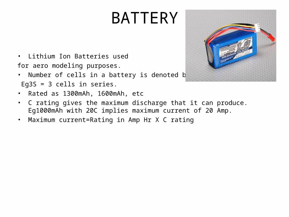
BATTERY
• Lithium Ion Batteries used for aero modeling purposes.• Number of cells in a battery is denoted by S rating. Eg3S = 3 cells in series.• Rated as 1300mAh, 1600mAh, etc • C rating gives the maximum discharge that it can produce. Eg1000mAh with 20C
implies maximum current of 20 Amp.• Maximum current=Rating in Amp Hr X C rating

landing gears
the part where Landing Gear have to be mounted must be very strong, so that it can take up the vibrations at the time of landing.
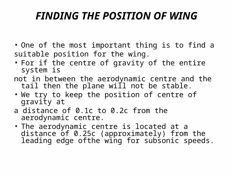
FINDING THE POSITION OF WING
• One of the most important thing is to find asuitable position for the wing.• For if the centre of gravity of the entire system isnot in between the aerodynamic centre and the tail
then the plane will not be stable.• We try to keep the position of centre of gravity ata distance of 0.1c to 0.2c from the aerodynamic
centre.• The aerodynamic centre is located at a distance
of 0.25c (approximately) from the leading edge ofthe wing for subsonic speeds.
FIXING WING1. The wing is attached to the fuselage with the help
of thin rubber tubes.2. With this we can separate the two parts and change the position of the wing as per the requirements.3. Like we can use a engine of better capacity.4. But with that the weight will increase and so theposition of centre of gravity will vary.5.5. So, we will have to readjust the wings So, we will have to readjust the wings
position.position.
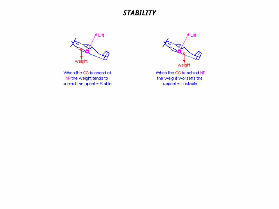
STABILITY
MORE TIPS… •Try to increase the dihedral angle gradually, in the spanwise directions. •Small winglet-type structures reduce drag. •MINIMIZE WEIGHT AS MUCH AS POSSIBLE!!! •Reduction in chord along spanwise direction (high aspect ratio) might increase Glide Ratio. •Round all leading edges in your model. •Reduction in fuselage cross section.
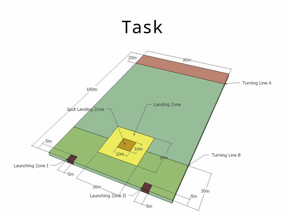
Task

Distance Plane should travel with load= 540mMax time that can be taken=3min
Average Speed Need to maintain=180m/min
3m/s10km/hr