basic engineering surveys for conservation practices ... · pdf filebasic engineering surveys...
TRANSCRIPT

BASIC ENGINEERING SURVEYS FORCONSERVATION PRACTICES TRAINING MODULE
Last Updated:02/01/01
Natural Resources Conservation ServiceMichigan

2
OBJECTIVE
This module is intended.to provide the participants with a basic understanding of engineeringsurvey priciples applicable to conservation practices. These principles include the types ofsurveys, types of survey equipment, notekeeping and note reduction.
Upon completion of this module, participants should have reached the ASK Level 3, performwith supervision, for the following types of surveys performed with an optical level(self-leveling level); topographic, cross-section, profile and bench level circuit.
INSTRUCTIONS
At the end of each section there are questions to be answered. The questions are designedto give you feedback on your ability to accomplish the module objectives.
If you have difficulty in a specific area, contact your facilitator (module leader).
You will need a calculator in several sections of this module.
INTRODUCTION
We perform surveys to define the landscape that has a problem we are trying to solve or todefine the landscape where we are installing a practice. The type of survey needed, the-accuracy required and the equipment to be used varies depending on the landscape and thepractice to be installed. During the field survey section of this module, the participant andfacilitator will spend time determining surveying needs with varying site conditions.
3
Section 1 - TYPES OF EQUIPMENT
There are several types of equipment used in surveying. We will be discussing onlyequipment that is typically used in NRCS work.
Survey Instruments
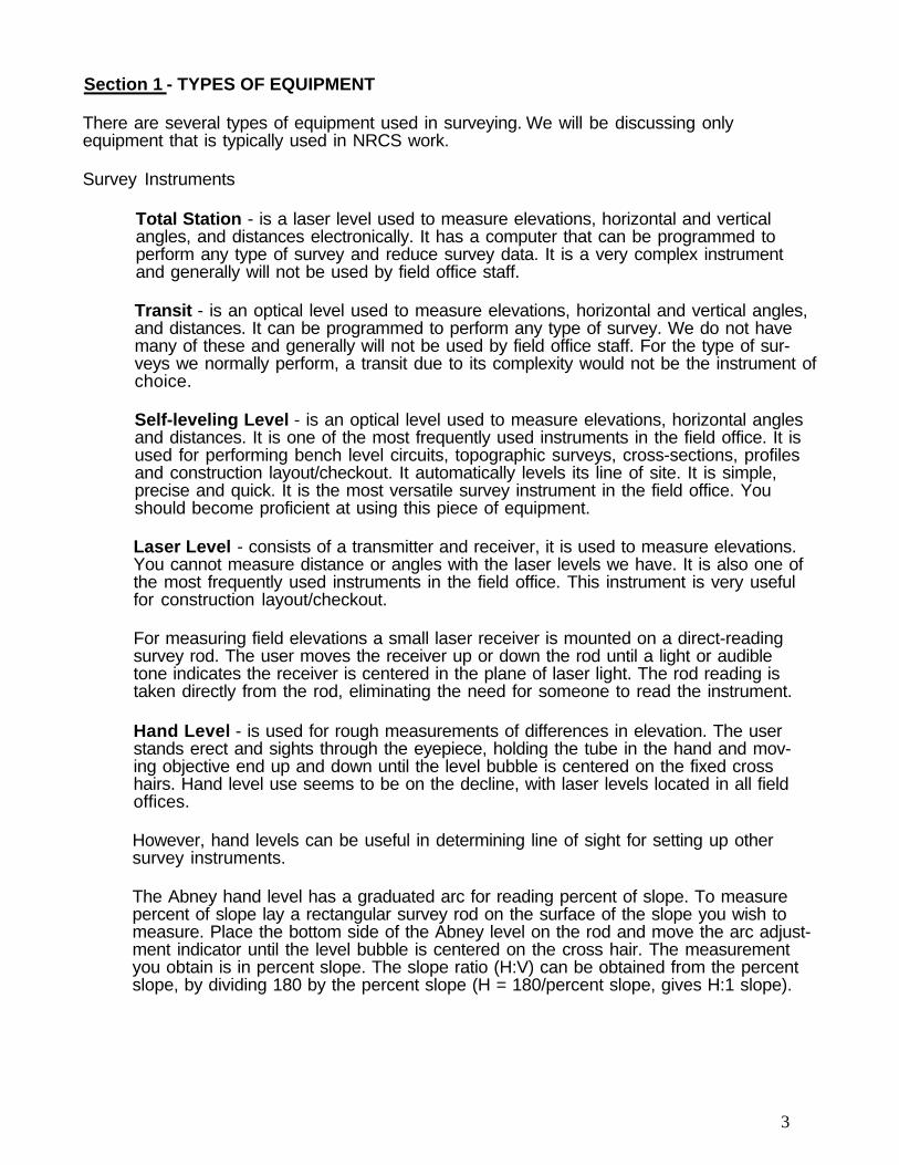
Total Station - is a laser level used to measure elevations, horizontal and verticalangles, and distances electronically. It has a computer that can be programmed toperform any type of survey and reduce survey data. It is a very complex instrumentand generally will not be used by field office staff.
Transit - is an optical level used to measure elevations, horizontal and vertical angles,and distances. It can be programmed to perform any type of survey. We do not havemany of these and generally will not be used by field office staff. For the type of sur-veys we normally perform, a transit due to its complexity would not be the instrument ofchoice.
Self-leveling Level - is an optical level used to measure elevations, horizontal anglesand distances. It is one of the most frequently used instruments in the field office. It isused for performing bench level circuits, topographic surveys, cross-sections, profilesand construction layout/checkout. It automatically levels its line of site. It is simple,precise and quick. It is the most versatile survey instrument in the field office. Youshould become proficient at using this piece of equipment.
Laser Level - consists of a transmitter and receiver, it is used to measure elevations.You cannot measure distance or angles with the laser levels we have. It is also one ofthe most frequently used instruments in the field office. This instrument is very usefulfor construction layout/checkout.
For measuring field elevations a small laser receiver is mounted on a direct-readingsurvey rod. The user moves the receiver up or down the rod until a light or audibletone indicates the receiver is centered in the plane of laser light. The rod reading istaken directly from the rod, eliminating the need for someone to read the instrument.
Hand Level - is used for rough measurements of differences in elevation. The userstands erect and sights through the eyepiece, holding the tube in the hand and mov-ing objective end up and down until the level bubble is centered on the fixed crosshairs. Hand level use seems to be on the decline, with laser levels located in all fieldoffices.
However, hand levels can be useful in determining line of sight for setting up othersurvey instruments.
The Abney hand level has a graduated arc for reading percent of slope. To measurepercent of slope lay a rectangular survey rod on the surface of the slope you wish tomeasure. Place the bottom side of the Abney level on the rod and move the arc adjust-ment indicator until the level bubble is centered on the cross hair. The measurementyou obtain is in percent slope. The slope ratio (H:V) can be obtained from the percentslope, by dividing 180 by the percent slope (H = 180/percent slope, gives H:1 slope).

4
TRIPODS
All survey instruments are placed on tripods with the exception of hand levels. With theinstrument in place tripods should be rough leveled, the plate. of the tripod should behorizontal.
SURVEY RODS
Survey rods or leveling rods are used to measure elevations. They are graduated in feet,tenths, and hundredths of a foot, with zero being at the bottom of the rod. The foot numbersare normally colored red. Numbers which denote tenths of a foot are normally black. Theblack strips are one-hundredth of a foot wide and are spaced one-hundredth of a foot apart.The top of each black strip is an even hundredth of a foot and the bottom is odd. Figure 1shows a section of a rod.
Surveying rods may also be used to measure horizontal distances. This is called stadia andwill be discussed in “measuring distance equipment”.
MEASURING DISTANCE EQUIPMENT
Pacing - Measurement by pacing consists of counting the number of steps betweentwo points. A natural stride or a pace can be used to determine your ‘stride factor’ or‘pace factor’.
Pacing may be used for approximate measurement when an error as large as 2 per-cent is permissible.
Taping - Taping is the method of measuring horizontal distances with a tape. Thismethod is very accurate. When measuring distance on a slope be sure to keep tapelevel on the line being measured (see figure 3).
Stadia - The stadia method is a much faster way to measure distances than taping,and is sufficiently accurate for many situations. Stadia is accurate within a few feetunder most conditions.
The equipment required for stadia measurements consists of a telescope with two extrahorizontal hairs, called stadia hairs, and a survey rod. Self-leveling levels and transits havestadia hairs. One of the stadia hairs is above the center horizontal cross hair and the other isan equal distance below it.
To take a stadia measurement, observe through the telescope the interval in meters or feeton the rod between the two stadia hairs when the rod is held vertically on some point. Thisinterval, called the stadia interval, is a direct function of the distance from the instrument tothe rod. On most instruments the ratio of this distance to the stadia interval may be taken as100 to 1. To determine the distance from the instrument to any given point, multiply the stadiainterval by 100.
The distances obtained by the stadia method are as measured along the line of sight fromthe instrument to the rod. If the line of sight is on an appreciable grade, you will need tomake a correction to obtain the true horizontal distance.
5
Section 1 - TYPES OF EQUIPMENT
QUESTIONS
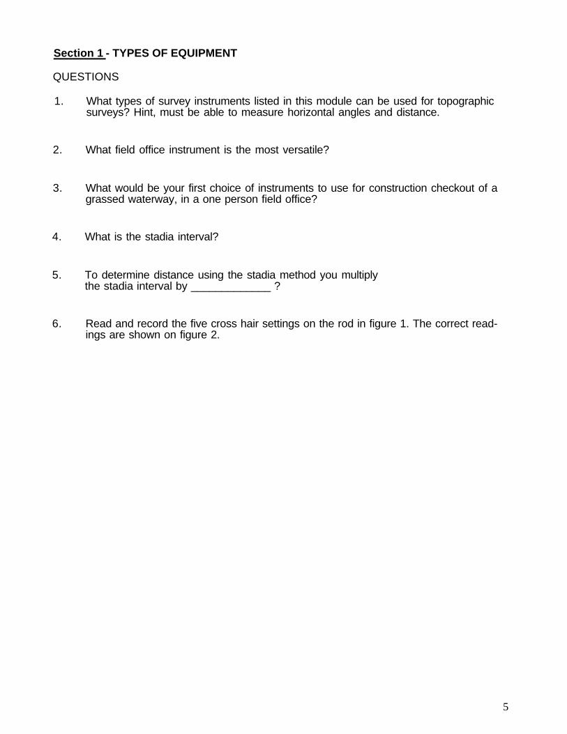
1. What types of survey instruments listed in this module can be used for topographicsurveys? Hint, must be able to measure horizontal angles and distance.
2. What field office instrument is the most versatile?
3. What would be your first choice of instruments to use for construction checkout of agrassed waterway, in a one person field office?
4. What is the stadia interval?
5. To determine distance using the stadia method you multiplythe stadia interval by _____________ ?
6. Read and record the five cross hair settings on the rod in figure 1. The correct read-ings are shown on figure 2.

6
Section 2 - TYPES OF SURVEYS
Installation of all permanent practices used in soil and water conservation work requireinformation regarding the relative elevation of designated points.
Common Terms
A bench mark (BM) is a point of known or assumed permanent elevation. Suchpoints may be marked with a brass pin or a cap set in concrete, a lone metal stakedriven into the ground, a specifically located point on a concrete bridge, culvert, orfoundation, or similar objects that are not likely to be disturbed.
A temporary bench mark (TBM) is a point of known or established elevation usuallyprovided for convenient reference in the course of surveys and construction whenpermanent bench marks are too far away or are inconveniently located. Such benchmarks may be established on wooden stakes set near a construction project or on nailsdriven into trees. Bench marks on trees will have more permanence if set near theground line where they will remain on the stump if the tree is cut and removed. Whentemporary bench marks are required to be maintained thru the winter, frost heave canbe a big problem for stakes that are not placed below the frost line. Frost heave canmove stakes up several tenths of a foot.
A turning point (TP) is a point on which the elevation is determined in the process ofleveling, but which is no longer needed after necessary readings have been taken. Aturning point should be located on a firm object, whose elevation will not change whilemoving the instrument setup. A small stone, fence post, temporary stake, or axe headdriven firmly into the ground usually is satisfactory.
A backsight is a rod reading taken on a point of known elevation. It is the first readingtaken on a bench mark or turning point. Backsights are sometimes recorded in the (+)column, because they are added to bench mark and turning point elevations.
A foresight is a rod reading taken on any point on which an elevation is to be deter-mined. Only one backsight is taken during each setup; all other rod readings are fore-sights. Foresights are sometimes recorded in the (-) column, because they are sub-tracted from the height of instrument.
Height of instrument (HI) is the elevation of the line of sight. It is determined by addingthe backsight rod reading to the known elevation of the point (BM, TBM, or TP) onwhich the backsight was taken.
Setting Up Levels
Before attempting to set up the level, be sure that the tripod wingnuts have been tight-ened. Be sure that after lowering the tripod legs to the ground the base plate of the tripodis relatively level by eye and that the tripod legs are spread at such an angle that thetripod is stable.
When setting a tripod on a slope, two of the tripod legs should be placed down slope andthe remaining leg up slope.
For a level with four leveling screws, line up the telescope over one pair of leveling screwsand center the bubble approximately, by turning screws in the opposite direction at the sametime. The process should be repeated with the telescope over the other pair of screws. Con-
7
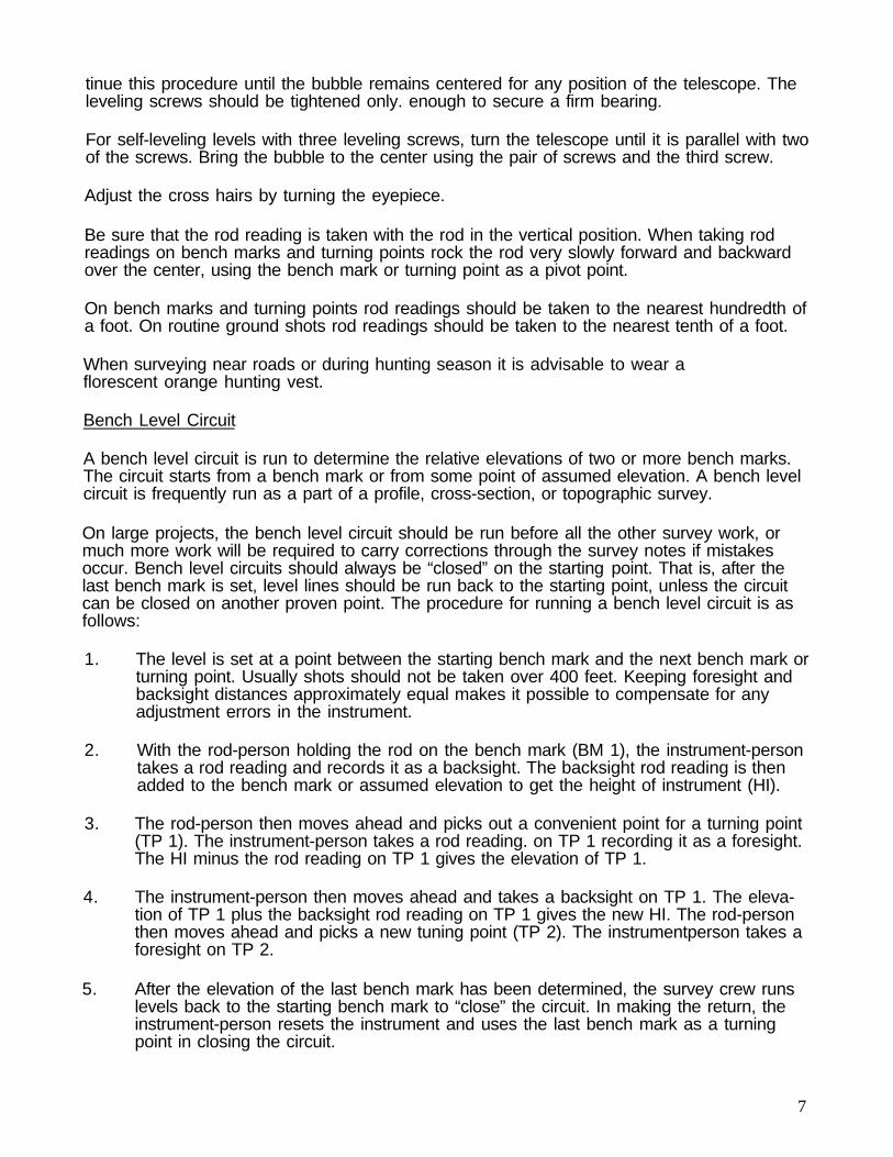
tinue this procedure until the bubble remains centered for any position of the telescope. Theleveling screws should be tightened only. enough to secure a firm bearing.
For self-leveling levels with three leveling screws, turn the telescope until it is parallel with twoof the screws. Bring the bubble to the center using the pair of screws and the third screw.
Adjust the cross hairs by turning the eyepiece.
Be sure that the rod reading is taken with the rod in the vertical position. When taking rodreadings on bench marks and turning points rock the rod very slowly forward and backwardover the center, using the bench mark or turning point as a pivot point.
On bench marks and turning points rod readings should be taken to the nearest hundredth ofa foot. On routine ground shots rod readings should be taken to the nearest tenth of a foot.
When surveying near roads or during hunting season it is advisable to wear aflorescent orange hunting vest.
Bench Level Circuit
A bench level circuit is run to determine the relative elevations of two or more bench marks.The circuit starts from a bench mark or from some point of assumed elevation. A bench levelcircuit is frequently run as a part of a profile, cross-section, or topographic survey.
On large projects, the bench level circuit should be run before all the other survey work, ormuch more work will be required to carry corrections through the survey notes if mistakesoccur. Bench level circuits should always be “closed” on the starting point. That is, after thelast bench mark is set, level lines should be run back to the starting point, unless the circuitcan be closed on another proven point. The procedure for running a bench level circuit is asfollows:
1. The level is set at a point between the starting bench mark and the next bench mark orturning point. Usually shots should not be taken over 400 feet. Keeping foresight andbacksight distances approximately equal makes it possible to compensate for anyadjustment errors in the instrument.
2. With the rod-person holding the rod on the bench mark (BM 1), the instrument-persontakes a rod reading and records it as a backsight. The backsight rod reading is thenadded to the bench mark or assumed elevation to get the height of instrument (HI).
3. The rod-person then moves ahead and picks out a convenient point for a turning point(TP 1). The instrument-person takes a rod reading. on TP 1 recording it as a foresight.The HI minus the rod reading on TP 1 gives the elevation of TP 1.
4. The instrument-person then moves ahead and takes a backsight on TP 1. The eleva-tion of TP 1 plus the backsight rod reading on TP 1 gives the new HI. The rod-personthen moves ahead and picks a new tuning point (TP 2). The instrumentperson takes aforesight on TP 2.
5. After the elevation of the last bench mark has been determined, the survey crew runslevels back to the starting bench mark to “close” the circuit. In making the return, theinstrument-person resets the instrument and uses the last bench mark as a turningpoint in closing the circuit.

8
6. After the final foresight on the starting BM is taken, the “error of closure” can bedetermined. This is the difference between the actual elevation of the BM and theelevation computed from the final foresight.
Ordinary survey accuracy should be attained in establishing bench marks, level circuitsinvolving six or more instrument setups, and surveys for drainage, irrigation, largechannels, and other major structural practices. Rough survey accuracy is adequate forlevel circuits of less than six instrument setups, for preliminary and reconnaissancesurveys, and for surveys for such conservation practices as diversions, waterways, andsmall ponds (see figure 4).
The check for closure should be done in the field to find errors and reduce returnvisits to the field. The closure error should be checked by adding all the backsightsand then adding all the foresights in the circuit. The difference should equal the errorof closure.
Self-leveling instruments and laser levels are the most often used instruments for benchlevel circuits. Total stations are also used for these surveys.
Profiles and Cross Sections
The object of profile leveling is to determine the elevation of the ground at measureddistances along a selected line, usually the centerline of a water course. These elevationscan then be plotted on profile paper at selected scales so that studies can be made ofgrades, depths, and high and low spots, and so that estimates can be made of quantitiesof cuts and fills.
Cross sections are simply profiles usually taken at right angles to a base line such as thecenter of a road, ditch, gully, or other selected base line. Cross sections may be run alongwith profile levels, or they may be run after the profile line has been staked and profileshave been taken.
Normally the starting station for surveys involving streams, waterways, ditches and gulliesshould be located at the upstream end and proceed in the direction of flow. Drainage sur-veys commonly proceed upstream with increasing station.
It is recommended that the beginning station for a survey be called something other than0+00 to prevent negative stations. 10+00 could be used as a starting station and if an addi-tion station was required above the starting station, 1000 feet would be available withoutcausing a negative station.
Normally the zero point (base line) of the cross section is the centerline of the gully, ditch orstream; however, it is not essential. In some cases, the zero point (base line) may be alongthe bank of a ditch. In any case, the zero of the cross section is on the base line. In the fieldnotes the direction of the cross section should be indicated. It is standard practice to refer to“right” and “left” when facing (downstream) the direction of progressive station of the profileline.
Self-leveling levels and laser levels are the most often used instruments for cross sectionsand profiles. Total stations are also used for these surveys.

Topographic Surveys
Topographic surveys, to obtain ground relief data and locations of natural and constructedfeatures, are the basis for many soil and water conservation projects.
Stadia surveys are the type most often used for topographic surveys. Stadia surveysusually consist of two parts: (1) the traverse, and (2) the taking of topography. The first isthe horizontal control, and the second is the vertical control.
Horizontal Control - The field work in this survey consists of determining horizontalangles (azimuths) to points or objects and obtaining distances between points bystadia. The azimuth angle is always measured clockwise from the zero azimuth. Onany given survey the position of zero azimuth should always be the same, usuallynorth. The zero azimuth can be set by magnetic north with a compass or by visuallyestimating north using roads or fence lines.
It is very important to maintain horizontal control when making “turns” during stadiasurveys. The most frequently used method for maintaining horizontal control is to havethe rod person find a new instrument set-up point. The instrument-person should takea rod reading with stadia (distance) and azimuth. This will allow horizontal control to bemaintained during plotting of the survey notes. When the instrument is moved to thenew setup point, zero azimuth should be set north.
Stadia surveys should be tied to fence line, roads and buildings, whenever possible,as this facilitates plotting and orienting the survey.
Vertical Control - is maintained during a stadia survey using the same methodsfor bench level circuits.
Self-leveling levels and total stations are the most commonly used instruments fortopographic surveys.
Construction Layout And Check-out
Construction layout surveys are surveys that are necessary to facilitate the construction of apractice. This type of survey is frequently a combination of a bench level circuit, profile andcross section survey.
Construction check-out surveys are surveys that are necessary to provide assurance that apractice was installed to proper elevation, grade and dimensions. These surveys are also acombination of other types of surveys.
Laser levels are the most frequently used instrument for construction layout andcheck-out.
10
Section 2 - TYPES OF SURVEYS
QUESTIONS
1. How is horizontal control maintained making “turns” during stadia surveys?
2. Are backsights added or subtracted from bench mark elevations to obtainthe height of instrument?
3. When is it permissible to not close a bench level circuit?
4. On bench marks and turning points rod readings should bemade to the nearest_______ of a foot.
5. On routine ground shots, read the rod to the nearest _________ of a foot.
6. Zero azimuth is usually set to the __________ .

Section 3 - NOTEKEEPING
The National Engineering Manual, Part 540 contains the policy on engineering surveynotekeeping. Part MI540.03 states that “survey notes will provide the minimum informationshown in the sample notes in Technical Release-62 and follow a format similar to TR-62samples.
The sample notes in this module follow TR-62, with slight modifications based onyears of experience.
It is suggested that you create sample notes for the type of surveys you use in your areaand keep these in your field survey book. You may want to add any conversion factors youmight find useful.
Bench Level Circuit
Figure 5 shows sample survey notes for a bench level circuit. At turning points, the foresightand elevation are on one line and the backsight and height of instrument are on the followingline. A blank line is left between each turning point and bench mark. By putting the backsightsand foresights on different lines it is easy to determine which was shot first. The blank linebetween turning points and bench marks makes notes easier to follow and allows room forbench mark descriptions on the adjacent page.
Topographic Survey
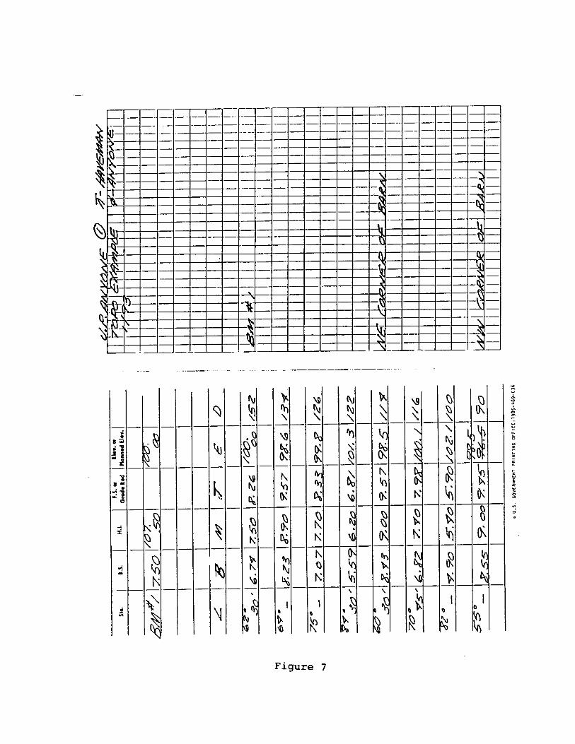
Figures 6 thru 8 show sample survey notes for a topographic survey. The columncontent is as follows:
< column - azimuthB column - bottom cross hair (stadia)M column - middle cross hair (rod reading)T column - top cross hair (stadia) E column - elevation (HI - M)D column - distance [stadia distance = (T-B)(100)].
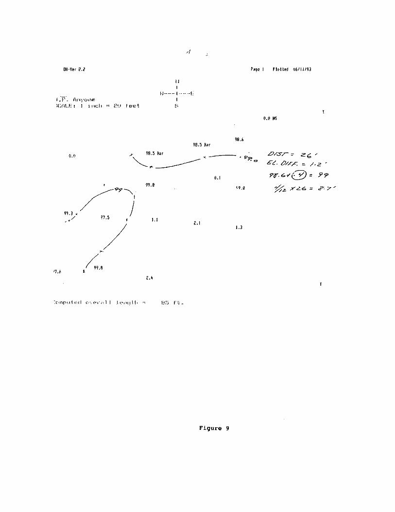
Figure 9 is a plot of the topographic survey using the Michigan Engineering Programs.
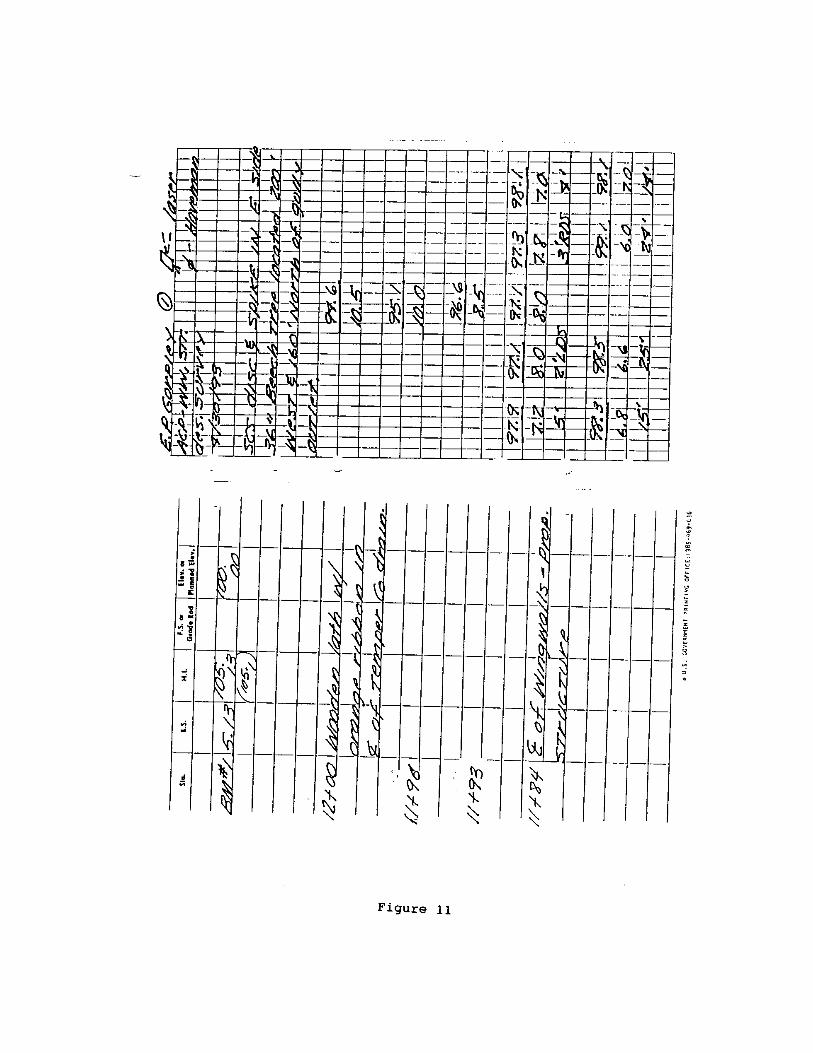
Waterway and Structure Survey
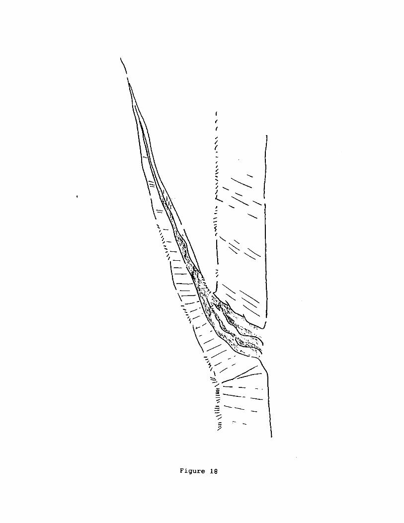
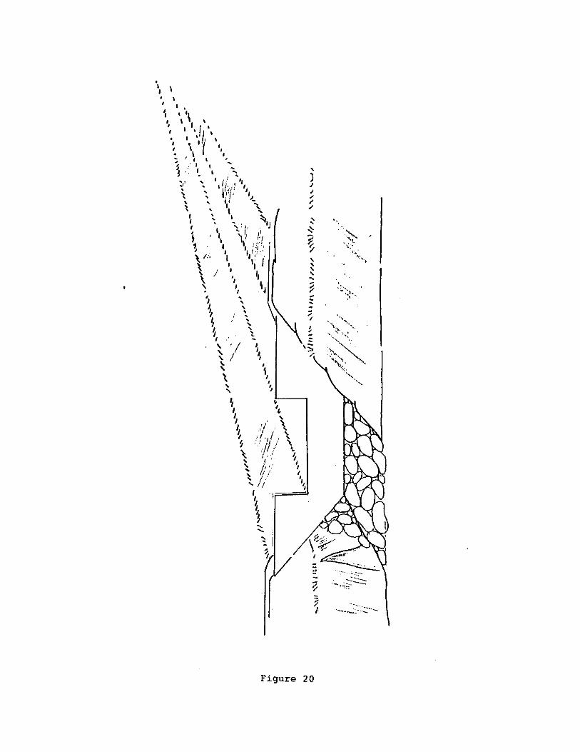
Figures 10 thru 13 are the design survey notes for a waterway and structure. The type ofsurveys used are profile, cross section and bench level circuit. See figures 18 thru 22 forisometric views of the site.
Figure 14 is the construction layout survey notes for the waterway and structure.
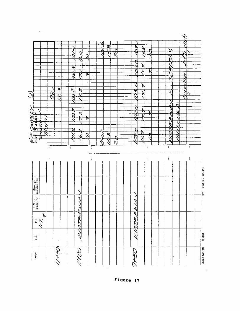
Figures 15 thru 17 are construction check-out survey notes for the waterway andstructure.

12
Section 3 - NOTEKEEPING
QUESTIONS
1. Where is the policy for survey notekeeping?
2. Why would you want to keep sample notes in your field survey book?

Section 4 - ANALYZING SITE CONDITIONS
To perform a survey there are some things you must be able to do that are obvious. You mustbe able to setup the instrument, take readings and keep survey notes. The most importanttasks are performed before the survey instrument is ever setup, that is to determine what theproblem is, what is causing the problem, formulate alternatives and then to decide whatalternatives you are surveying for. Many times during the design phase you will find that thepractice you thought would work best to solve a problem is not a viable alternative based onthe site conditions that you have to work with. If you have performed a survey with only onetype of practice in mind, you may be making another trip for additional survey data.
Analyzing site conditions is illustrated in figures 18 thru 22. Figure 18 shows a gully along aditch bank. You should discuss the problem with the landowner to obtain his/her ideas. How-ever, many times the landowner may not know what is causing the problem or what the prob-lem is. You as the technical person must be able to recognize the problems and developsolutions. What are the problems on this site? How about gully erosion and unstable outlet.What is causing the problems on this site? Excess surface water is causing the problem.What are some alternatives for solving this problem? To control the gully erosion you mightconsider a water and sediment control basin up slope of the problem area or a grassed wa-terway at the problem area. To provide a stable outlet you will need some kind of grade stabi-lization structure (GSS). You might select a pipe drop structure, straight drop spillway, boxspillway or a chute spillway. What alternatives you choose will decide the extent of yoursurvey. Figures 19 and 20 show the alternatives that were chosen. What type of survey isneeded for the solution shown in figure 20? Figure 21 shows a profile and cross-sections ofthe proposed waterway that are needed, as well as a cross-section at the structure site.Figure 22 shows actual stations and crosssection points.
Your survey must provide enough information to do the design and enough data to establishquantities. For a contractor to bid a job he/she will need reasonable quantity estimates.
You must develop the ability to recognize the problem to be solved and envision ways tosolve it. Only then can you perform a good survey.
Section 4 - ANALYZING SITE CONDITIONS
QUESTIONS
1. An engineering survey must be able to provide enough information to and
2. You perform the survey first and then decide what type of practice will fit the site. (Trueof False)
14
Section 5 - CARE AND HANDLING OF EQUIPMENT
To set up an instrument and tripod, remove the tripod cap and place it in the instrumentbox for safekeeping. Blow dust and dirt particles from the tripod head before mountinginstrument.
The sunshade should be used regardless of the weather.
When placing the instrument in the case, loosen the lower clamp screw and replace theobjective lens cap on the telescope. After placing the instrument into the case, tighten thetelescope clamp screw.
Do not lubricate instrument leveling screws.
Do not rub telescope lenses. These lenses are made of soft glass that scratches easily. Dustthem with a clean, soft, camel’s hair brush, or wipe them very carefully with a clean, softcloth.
Never store a wet instrument in the case. Store equipment in a dry place.
Tripod screws should be loosened before storing.
Survey instruments should be carried in the instrument case in the cab of the vehicle, pref-erably on the floor or in a wellpadded equipment box. Rods should be in cases and carriedwhere they will be protected from weather.
Section 5 - CARE AND HANDLING OF EQUIPMENT
QUESTIONS
1. What type of oil should be used on instrument leveling screws?
2. Tripod screws should be loose then tripod is stored. (True or False)

Section 6 - FIELD PRACTICE
Actual surveys, notekeeping, note reduction and survey plotting should be performed byparticipants with supervision from facilitator’s (module leaders).
The following types of surveys should be performed:Bench level circuitCross sectionProfileTopographicConstruction layout/check out
Survey notes should be reduce and plotted by hand and using the “Michigan EngineeringPrograms”.

16
Recommended Survey Types for Conservation Practices
PRACTICE SURVEY TYPES
Agrichemical Containment Facility Bench Level Circuit, Topo, Profiles and Cross Sections
Animal Trails and Walkways Bench Level Circuit, Topo, Profiles and Cross Sections
Dike Bench Level Circuit, Profiles and Cross Sections
Diversion Bench Level Circuit, Profiles and Cross Sections
Fueling Facility, Above Ground Storage Bench Level Circuit, Topo, Profiles and Cross Sections
Grade Stabilization Structure Bench Level Circuit, Topo, Profiles and Cross Sections
Grassed Waterway Bench Level Circuit, Profiles and Cross Sections
Heavy Use Protection Bench Level Circuit, Topo, Profiles and Cross sections
Pond Topo, Profiles and Cross Sections
Pumping Plant for Water Control Topo, Profiles and Cross Sections
Recreation Land Grading and Shaping Bench level circuit, Topo, Profiles and Cross Sections
Recreation Trail and Walkway Bench Level Circuit, Topo, Profiles and Cross Sections
Roof Runoff Management Bench Level Circuit, Topo, Profiles and Cross Sections
Spring Development Bench Level Circuit, Topo, Profiles and Cross Sections
Streambank Protection Bench Level Circuit, Topo, Profiles and Cross Sections
Stream Crossing and Livestock Access Topo, Profiles and Cross Sections
Subsurface Drain Bench Level Circuit, Topo, Profiles and Cross Sections
Surface Drainage, Field Ditch Bench Level Circuit, Profiles and Cross Sections
Surface Drainage, Main or Lateral Bench Level Circuit, Profiles and Cross Sections
Trough or Tank Topo, Profiles and Cross Sections
Waste Storage Facility Topo, Profiles and Cross Sections
Water and Sediment Control Basin Bench Level Circuit, Topo, Profiles and Cross Sections
Wetland Restoration Bench Level Circuit, Topo, Profiles and Cross Sections