basic design study report on the project …open_jicareport.jica.go.jp/pdf/11814076_01.pdfwe are...
TRANSCRIPT

BASIC DESIGN STUDY REPORT ON
THE PROJECT FOR
THE VIENTIANE WATER SUPPLY DEVELOPMENT IN
LAO PEOPLE’S DEMOCRATIC REPUBLIC
SEPTEMBER 2005
JAPAN INTERNATIONAL COOPERATION AGENCY GRANT AID MANAGEMENT DEPARTMENT
PREFACE
In response to a request from the Government of Lao People’s Democratic Republic, the Government of Japan
decided to conduct a basic design study on the Project for the Vientiane Water Supply Development and entrusted
the study to the Japan International Cooperation Agency (JICA).
JICA sent to Lao PDR a study team twice from July 3 to August 6, 2004 and February 22 to March 6, 2005.
The team held discussions with the officials concerned of the Government of Lao PDR, and conducted a field
study at the study area. After the team returned to Japan, further studies were made. Then, a mission was sent
to Lao PDR in order to discuss a draft basic design, and as this result, the present report was finalized.
I hope that this report will contribute to the promotion of the project and to the enhancement of friendly relations
between our two countries.
I wish to express my sincere appreciation to the officials concerned of the Government of Lao People’s
Democratic Republic for their close cooperation extended to the teams.
September 2005
Seiji Kojima
Vice-President
Japan International Cooperation Agency
September 2005
LETTER OF TRANSMITTAL
We are pleased to submit to you the basic design study report on the Project for the Vientiane Water Supply
Development in Lao People’s Democratic Republic.
This study was conducted by Nihon Suido Consultants Co., Ltd., under a contract to JICA, during the period from
June 2004 to September 2005. In conducting the study, we have examined the feasibility and rationale of the
project with due consideration to the present situation of Lao PDR and formulated the most appropriate basic
design for the project under Japan’s grant aid scheme.
Finally, we hope that this report will contribute to further promotion of the project.
Very truly yours,
Takemasa Mamiya
Project Manager,
Basic Design Study Team on
The Project for the Vientiane
Water Supply Development
Nihon Suido Consultants Co., Ltd.

Location Map/ Project Location Map

Lao PDR
Vientiane
VientianeCapital City
LocationMap
8 km0 642

Project Location Map
Dongdok
Phonekheng
Phonethane
PhonetongXamkhe
Nongteng
Km12
Treatment PlantElevated TankBooster Pumping StationExisting Pipelines
Salakham
Kaolieo Treatment Plant Existing : 20,000 m3/day Expansion : 40,000 m3/day Rehabilitation Work
Chinaimo Treatment Plant Existing : 80,000 m3/day Improvement Work New Reservoir New Distribution Pumping Station
Proposed Distribution PipelinesProposed Transmission Pipelines
150L=2.6 km
L=0.5 km 700 L=1.6 km
600L=4.7 km 400
150L=1.9 km
700L=0.7 km
L=0.8 km150
Km6 Booster PumpingStation Rehabilitation Wrok

List of Tables & Figures

List of Tables & Figures List of Table Table 2-1 Population of Seven Districts in Vientiane ................................................................................2-7 Table 2-2 Future Water Demand ................................................................................................................2-8 Table 2-3 Components of Kaolieo Treatment Plant Expansion ...............................................................2-23 Table 2-4 Components of Rehabilitation Work of Kaolieo Treatment Plant ...........................................2-32 Table 2-5 Components of Improvement Work of Chinaimo Treatment Plant .........................................2-42 Table 2-6 Components of Rehabilitation Work of Km6 Booster Pumping Station .................................2-45 Table 2-7 Required Pipe Specifications ...................................................................................................2-53 Table 2-8 Procurement Plan for Construction Materials........................................................................2-105 Table 2-9 Major Work Items and Methods for Quality Control.............................................................2-108 Table 2-10 Water Tariff Collection Rate ..................................................................................................2-116 Table 2-11 NPVC Financial Situation from 2000 to 2003.......................................................................2-120 List of Figures Figure 1-1 Location Map of Dongmark Khay Project.................................................................................1-2 Figure 2-1 Monthly Temperature in Vientiane ............................................................................................2-4 Figure 2-2 Monthly Precipitation and Water Level of the Mekong River in Vientiane...............................2-5 Figure 2-3 Future Water Demand and Supply Capacity (Planned by the previous JICA M/P & F/S).................................................................................................................................2-9 Figure 2-4 Future Water Demand and Supply Capacity (including consideration of the Dongmark Khay Project) .......................................................................................................2-10 Figure 2-5 Layout of Kaolieo Treatment Plan...........................................................................................2-14 Figure 2-6 Treatment Process for Kaolieo Treatment Plant Expansion.....................................................2-15 Figure 2-7 Layout of Rehabilitation Work of Kaolieo Treatment Plant ....................................................2-28 Figure 2-8 Water Treatment Process of Kaolieo Treatment Plant .............................................................2-29 Figure 2-9 Separation of Transmission and Distribution lines at the Chinaimo Treatment Plant .......................................................................................................................................2-39 Figure 2-10 layout of Improvement Work of Chinaimo Treatment Plant....................................................2-41 Figure 2-11 Layout of Rehabilitation/Improvement of Km6 Booster Pumping Station .............................2-44 Figure 2-12 Transmission and Distribution System (Previous JICA M/P & F/S) .......................................2-46 Figure 2-13 Contour Line of the Residual Pressure in the Distribution Network Considering the Effects of the Donmark Khay Project..........................................................2-49 Figure 2-14 Transmission/distribution System to/in northern part of city requested by GOL compared with the Revised Scope which considers the Effects of the Dongmark Khay Project ........................................................................................................2-50 Figure 2-15 Water Transmission and Distribution System incorporating the Dongmark Khay Project ........................................................................................................2-52 Figure 2-16 AFD Proposed Distribution Pipe Route...................................................................................2-54 Figure 2-17 Location of Two Pipeline Routes which were not Included in the AFD project......................2-55 Figure 2-18 Duplication of the Pipeline Route and the route of No.1 road project.....................................2-60 Figure 2-19 Location of Distribution Pipe No.1 in Road No.1 ...................................................................2-61

Figure 2-20 Location of Transmission Pipe No.2 along the Road No.1 from Chinaimo Junction .................................................................................................................2-61 Figure 2-21 Location of Distribution Pipe No.4 along the Road No.1 from Chinaimo Junction .................................................................................................................2-62 Figure 2-22 Location of Distribution Pipe No.1 along the T2 Road (from Road No.1 to 2.86 km point) .......................................................................................2-63 Figure 2-23 Location of Distribution Pipe No.1 along the T2 Road (beyond the 2.86 km point)....................................................................................................2-63 Figure 2-24 Location of pipeline along the Road No.13 .............................................................................2-64 Figure 2-25 Pipe alignment located 0.4 km from the Chinaimo Treatment Plant .......................................2-65 Figure 2-26 Pipe alignment located 0.5 km from the Kaolieo Treatment Plant ..........................................2-66 Figure 2-27 Pipe alignment located 5.08 to 6.06 km from the Kaolieo Treatment Plant ............................2-66 Figure 2-28 Pipe alignment located 6.06 to 6.77 km from the Kaolieo Treatment Plant ............................2-67 Figure 2-29 Pipe alignment along the Road to Naxyaythong......................................................................2-67 Figure 2-30 Typical Structure of Pipe Bridge..............................................................................................2-68 Figure 2-31 Typical Structure of Culvert Crossing .....................................................................................2-68 Figure 2-32 Typical Air Valve Assembly.....................................................................................................2-69 Figure 2-33 Typical Blow-off Assembly .....................................................................................................2-69 Figure 2-34 Concrete Thrust Block .............................................................................................................2-70 Figure 2-35 Restrain Joint ...........................................................................................................................2-70 Figure 2-36 Expansion of Kaolieo Treatment Plant, General Plan..............................................................2-72 Figure 2-37 Expansion of Kaolieo Treatment Plant, Water Flow Diagram.................................................2-73 Figure 2-38 Expansion of Kaolieo Treatment Plant, Details of Intake Gate ...............................................2-74 Figure 2-39 Expansion of Kaolieo Treatment Plant, Flocculation Basin, Sedimentation , Filter.......................................................................................................................................2-75 Figure 2-40 Expansion of Kaolieo Treatment Plant, Details of Sedimentation Basin-1 .............................2-76 Figure 2-41 Expansion of Kaolieo Treatment Plant, Details of Sedimentation Basin-2 .............................2-77 Figure 2-42 Expansion of Kaolieo Treatment Plant, Details of Filter .........................................................2-78 Figure 2-43 Expansion of Kaolieo Treatment Plant, Reservoir, Chemical/Office Bldg and Pumping Station-1 ......................................................................2-79 Figure 2-44 Expansion of Kaolieo Treatment Plant, Reservoir, Chemical/Office Bldg and Pumping Station-2 ......................................................................2-80 Figure 2-45 Expansion of Kaolieo Treatment Plant, Reservoir, Chemical/Office Bldg..............................2-81 Figure 2-46 Rehabilitation of Kaolieo Treatment Plant, General Plan........................................................2-82 Figure 2-47 Rehabilitation of Kaolieo Treatment Plant, Water Flow Diagram ...........................................2-83 Figure 2-48 Rehabilitation of Kaolieo Treatment Plant, Details of Intake Tower.......................................2-84 Figure 2-49 Rehabilitation of Kaolieo Treatment Plant, Details of Receiving Well ...................................2-85 Figure 2-50 Rehabilitation of Kaolieo Treatment Plant, Plan of Sedimentation Basin (Before Rehabilitation) ......................................................................2-86 Figure 2-51 Rehabilitation of Kaolieo Treatment Plant, Plan of Sedimentation Basin (After Rehabilitation) .........................................................................2-87 Figure 2-52 Rehabilitation of Kaolieo Treatment Plant, Filter (Before Rehabilitation) ............................2-88 Figure 2-53 Rehabilitation of Kaolieo Treatment Plant, Filter (After Rehabilitation) ..............................2-89

Figure 2-54 Rehabilitation of Kaolieo Treatment Plant, Details of Pumping Station .................................2-90 Figure 2-55 Improvement of Chinaimo Treatment Plant, General Plan......................................................2-91 Figure 2-56 Improvement of Chinaimo Treatment Plant, Water Flow Diagram .........................................2-92 Figure 2-57 Improvement of Chinaimo Treatment Plant, Plan of Reservoir and Pumping Station..............................................................................................................2-93 Figure 2-58 Improvement of Chinaimo Treatment Plant, Section of Reservoir and Pumping Station..............................................................................................................2-94 Figure 2-59 Rehabilitation of Km6 Booster Pumping Station, General Plan..............................................2-95 Figure 2-60 Rehabilitation of Km6 Booster Pumping Station, Detail of Existing Pumping Station ......................................................................................................2-96 Figure 2-61 Typical Drawings of Valve.......................................................................................................2-97 Figure 2-62 Typical Drawing of Valve Chamber.........................................................................................2-98 Figure 2-63 Typical Drawing of Pipe Bridge ..............................................................................................2-99 Figure 2-64 Project Implementation Process.............................................................................................2-100 Figure 2-65 Route of Overland Transportation .........................................................................................2-107 Figure 2-66 Implementation Schedule ......................................................................................................2-110 Figure 2-67 Organization Chart for Chinaimo/Kaolieo Treatment Plants.................................................2-114 Figure 2-68 Financial Balance of the NPVC.............................................................................................2-121 Figure 2-69 Unit Water Tariff Change by Monthly Water Consumption for Group 1...............................2-122 Figure 2-70 Unit Water Tariff Change by Monthly Water Consumption for Group 2...............................2-122 Figure 2-71 Unit Water Tariff Change by Monthly Water Consumption for Group 3...............................2-122

Abbreviations

Abbreviations
ADB Asian Development Bank AFD French Development Agency BD Basic Design DCTPC Department of Communication, Transport, Post and Construction, Vientiane Capital City D/D Detailed Design DFR Draft Final Report DHUP Department of Housing and Urban Planning, MCTPC DIP (DCIP) Ductile Cast Iron Pipe FS (F/S) Feasibility Study GM General Manager GOJ Government of Japan GOL Government of Lao PDR HWL High Water Level ISO International Organization for Standardization IWD Internal Waterway Department JICA Japan International Cooperation Agency Lao PDR Lao People's Democratic Republic LDCD Leakage Detection and Control Division, NPVC Lpcd liter per capita day, unit of water consumption per day per capita LWL Low Water Level MCTPC Ministry of Communication, Transport, Post and Construction MD Minute of Discussion MOF Ministry of Finance MP (M/P) Master Plan MPH Ministry of Public Health NPVC (NPNL)
Nam Papa Vientiane Capital City, Water Supply Company of the Vientiane Capital City, (NPNL in Lao Language)
NRW Non Revenue Water NSC National Statistical Centre PVC Polyvinyl Chloride Pipe S/V Construction Supervision UFW Unaccounted-for Water VUDAA Vientiane Urban Development and Administration Authority WASA Water Supply Authority, DHUP, MCTPC WB World Bank WRCC Water Resources Coordination Committee WTP Water Treatment Plant

Summary

- Summary 1 -
Summary
The current water supply system in Vientiane is getting worse and worse, due to the high demand of water trigger
by the population increase, the improvement of life standard, and the expansion of industry and living area. To
cope with the high water demand, two existing water facilities are overworking. At the same time, the old water
facilities and equipment, high leakage ratio, and low water pressure unable to supply water stably.
The Government of Lao People’s Democratic Republic (GOL) developed the first “Five Year National
Development Plan” in 1981, and is implementing their fifth “Five Year National Development Plan (2001 to
2005)”. The GOL has also formulated a Long Term Development Plan which has a target year of 2020. In the
Long Term Development Plan, development of social infrastructure such as water and sewerage are given the
highest priority. Based on these two plans, the Ministry of Communication, Transport, Post and Construction
(MCTCP) prepared the “Development Plan for Communication, Transport, Post and Construction, Year 1996 –
2020” in September 1997. The key targets of this plan include development of the water supply sector to
achieve a national average water supply service ratio of 90 %, with a ratio of 100 % in urban areas and 80 % in
smaller scale towns.
In addition, in September 1999, the prime ministerial office issued the prime ministerial decree “Prime Ministerial
Decision on Management and Development of Water Supply Sector (No.37)”. The decree stated that a water
supply service ratio in urban areas of 80 % should be achieved as soon as possible and that Vientiane (the nation’s
capital city) should be assigned the highest priority for water supply sector development. Due to financial and
budgetary constraints, progress of development for the water supply sector has been delayed and is therefore
behind the targets set out in the development plans and stated in the above mentioned.
Based on this situation, GOL requested Japan International Cooperation Agency (JICA) to conduct the social
development study titled “The Study on Vientiane Water Supply Development Project” from March 2003 to
February 2004. After the social development study, GOL requested Japanese Grant Aid for the Vientiane Water
Supply Development Project. The following components are planned to achieve the project purpose:
• expansion of Kaolieo Treatment Plant to a capacity of 40,000 m3/day;
• rehabilitation of the existing Kaolieo Treatment Plant to achieve its 20,000 m3/day capacity;
• improvement of the existing Chinaimo Treatment Plant including separation of the transmission/distribution
pipelines, construction of a new distribution reservoir (with a capacity of 7,500 m3) and construction of a
new pumping station;
• rehabilitation of the existing Km6 booster pumping station; and
• installation of transmission (approximately 0.7km) and distribution (approximately 11.9km) mains.
Under the Basic Design Study, the Study Team was dispatched to Lao PDR a study team for discussions with
agencies concerned and for site investigation twice from July 3 to August 6, 2004 and February 22 to March 6,

- Summary 2 -
2005. After home work in Japan, Draft Final Report was presented and discussed in Lao PDR from May 23 to
June 2 in 2005.
Project objectives of the Basic Design Study are to attain achievement of stable water supply and improve the
water supply service ratio in Vientiane City.
The Basic Design was conducted in accordance with the principles listed below:
• The GOL requested that the Project be implemented based on the results of a social development study
(feasibility study) titled “The Study on Vientiane Water Supply Development Project” which was completed
by JICA in January 2004. Any changes to the Project context since that study were investigated, quantified
and the project scope was appropriately modified. These changes related to the national sector development
plan, social changes, population growth, increased per capita water demand etc.
• The most effective and efficient plan for expansion, rehabilitation, and improvement of treatment plants was
formulated to mitigate the water shortage situation in Vientiane.
• Consistency in scope was maintained between Japan’s Grant Aid project and the GOL Dongmark Khay
project.
• The design assumed that the Dongmark Khay project will be implemented by the GOL and that the
transmission/distribution system in the service area of the Dongmark Khay treatment plant will be developed
by the GOL.
• It was assumed that the GOL will coordinate input from the French Development Agency (AFD) when
undertaking the Dongmark Khay project.
Based on the above principles, the following components are planned to achieve the project purpose:
Components of Kaolieo Treatment Plant Expansion
Name of Facility / Equipment Component of Expansion Work
Intake Structure Type : Intake Pipe Type RC Structure, 1Basin Intake Pumping Well : W8.00 m × L3.50 m × D15.50 m Pump House : W8.00m × L6.00 m (48.0 m2 ), Pump House Floor : Grating
River Bank & River Bed Protection
Slope Protection : Gabion Mattress Work Anchor of Slope Protection : Pipe Pile Anchor Work (head of piles will be connected each other by RC) Bed Protection : Soda Mattress Work Submersible Pump : 15.3 m3/min × 19.5 m × 75 kW × 3 Units(1-Standby) Intake Pump Check Valve : D350mm × 3 Units Discharge Valve : D350 mm Electric Motor-drive Type Short Body Type Butterfly Valve (Horizontal Type) × 3 Units
Intake Facilities
Inlet Pipes & Stop Valves
Inlet Pipe : D1,000 mm × 3 Pieces Inlet Screen : Fixed Bar Screen x 3 Sets Stop Valve : D1,000 mm Short Body Type Butterfly Valve (Vertical Type) with Manual Operating Stand x 3 Units

- Summary 3 -
Name of Facility / Equipment Component of Expansion Work
Flashing Piping Devices for Prevention of Pile-up Soil
Gate Valve : D300 mm Sluice Valve with Manual Operating Stand × 7 Units Flashing Pipe : D300 mm × 2 Pieces Flashing pipe with Slit : D300 mm × D150 mm × 1 Piece Stop Log for Bottom Pipe : D1,000 mm with Manual Operating Stand
Crane Equipment 5 ton Electric Motor-drive Chain Hoist Crane (Traversing, Traveling, Hoisting) × 1 Unit Raw Water Transmission Main
DIP : D700 mm × L15 m DIP : D500 mm × L15 m
Raw Water Flow Meter Chamber & Flow Control Valve Chamber
Raw Water Transmission Facilities
Flow Meter & Flow Control Valve Facility
Flow Control Valve : D500 mm Tooth-shaped Disk Type Butterfly Valve (Horizontal Type) × 2 Units (Electric Motor-drive Type × 1 Unit、 Manual Type × 1 Unit)
Receiving Well RC Structure、1Basin、Detention Time = 2.3 min. Dimension : W2.80 m × L5.60 m × D5.10 m × E.D4.50 m
Receiving Well & Mixing Well Facilities Mixing Well Mixing Type : Gravitational Force Mixing by Weir Type
RC Structure, 1 Basin、Detention Time = 1.0 min. Dimension : W2.80 m × L2.80 m × D5.10 m × E.D3.84 m
Flocculation Basin Flocculation Type : Baffled Channel Type RC Structure, 4 Basin、Detention Time = 23.7 min. (Except Outlet Zone) Dimension : W8.55 m × L10.15 m × Av.D3.70 m × Av.E.D3.05 m
Sedimentation Basin
Sedimentation Type : Conventional Type – Uni-flow Type (Horizontal Flow) RC Structure, 4 Basin、Detention Time = 2.1 hr (Substantially = 3.5hr) Dimension : W8.55 m × L33.00 m × Av.D4.05 m × Av.E.D3.43 m Flocculation Basin : Steel Plate Slide Gate for Sludge Drain – 23 Sets / Basin Sedimentation Basin : D300 mm Sludge Drain Valve with Manual Operating Stand × 8 Units Enhanced Sludge Drain System for Sedimented Sludge : Pressurized Piping with Slit D250 mm × 4 Lots (Utilizing Pressurized Raw Water)
Flocculation & Sedimentation Facilities
Sludge Drain Facilities (Flocculation &Sedimentation Basin)
Pressurized Cleaning Piping System for Flocculation and Sedimentation Basins : Utilizing Raw Water Pumping Well : RC Structure, 1 Basin、Detention Time = 10 min.(V=7.5m3) Submersible Pump : 0.75 m3/min × 60 m × 15 kW × 1 Unit Filtration Type : Rapid Sand Filtration - Air Scouring Type RC Structure, 6 Basin、 Filtered Area = 49.6 m2/Basin ( Dimension : W4.55 m × L10.5 m) Filtration Rate : 147.8 m/d Back Wash Rate = 0.36 m3/min/m2
Air Scouring Rate = 1.00 m3/min/m2 Sand : Effective Size = 1.0 mm Depth of Sand = 1.0 m
Rapid Sand Filtration Basin
Under drain System : Porous Plate Type Inlet Valve : D700 mm Electric Motor-drive Type Wafer–type Butterfly Valve with Locking Device × 6 Units (1 Unit/Basin) Back Wash Valve : D500 mm Electric Motor-drive Type Wafer–type Butterfly Valve × 6 Units (1 Unit/Basin)
Operating Valves for Filtration
Air Scouring Valve : D250 mm Electric Motor-drive Type Wafer–type Butterfly Valve × 6 Units (1 Unit/Basin)
Flow Control Device
Flow Control Device (Valvoset) × 6 Sets (1 Set/Basin)
Back Wash Pump : Horizontal Double Suction Volute Pump D400mm × D250 mm × 17.9 m3/min × 12 m × 55 kW × 2 Units (1- Stand -by) Foot Valve : D400 mm × 2 Units Suction Valve : D400 mm Short Body Type Butterfly Valve (Manual Operate) × 2 Units Check Valve : D400 mm × 2 Units Discharge Valve : D400 mm Electric Motor-drive Type Wafer–type Butterfly Valve (Horizontal Type) × 2 Units
Back Wash Pumping Equipment
Flow Meter : D500 mm Orifice-type × 1 Unit Flow Control Valve : D500 mm Short Body Type Mamual Type Butterfly Valve (Horizontal Type) × 1 Unit Air Blower : D250 mm Roots-type 49.6 m3/min × 3,000 mmAq × 37 kW × 2 Units (1-Stand-by)
Filtration Facilities
Air Scouring Equipment
Check Valve : D250 mm × 2 Units Discharge Valve : D250 mm Electric Motor-drive Type Wafer–type Butterfly Valve (Horizontal Type) ×2 Units

- Summary 4 -
Name of Facility / Equipment Component of Expansion Work
Flow Meter : D250mm Orifice-type × 1 Unit Filtered Flow Measurement Chamber
RC Structure, 1Basin、Detention Time = 1.8 min. Dimension : W3.00 m × L6.05 m × D3.70 m × E.D2.98 m
Flow Measurement & Mixing Chamber Chlorine Mixing
Chamber Mixing Type : Gravitational Force Mixing by Weir Type RC Structure, 1 Basin、Detention Time = 0.7 min. Dimension : W3.00 m × L3.00 m × D3.70 m × E.D2.49 m
Piping to New Reservoir
DIP : D700 mm × L110 m Filtered Water Connecting Piping Piping to Existing
Reservoir DIP : D600 mm × L110 m Connecting Valve : D600 mm Short Body Type Butterfly Valve (Horizontal Type) with Manual Operating Stand x 1 Unit RC Structure, Effective Capacity = 10,600 m3, Detention Time = 5.8 hr. Dimension : Reservoir - W25.0 m × L50.0 m × D5.0 m × E.D4.0 m × 2 Basins
Pumping Well - W30.0 m × L5.0 m × D6.5 m × E.D4.0 m × 1 Basin Inlet Valve : D700 mm Short Body Type Butterfly Valve (Vertical Type) with Manual Operating Stand x 2 Units Connecting Valve : D700 mm Short Body Type Butterfly Valve (Vertical Type) with Manual Operating Stand x 2 Units Over-flow Pipe : D600mm
Distribution Facility
Clear Water Reservoir
Ventilation Device : 1 Lot Distribution Pump Building
RC Structure, Building Area = 300 m2 ( Dimension : W30.4 m × L10.0 m) Distribution Pump : Horizontal Double Suction Volute Pump D300mm x D200 mm × 12.1 m3/min × 75 m × 220 kW × 4 Units (1 Stand-by) Foot Valve : D300 mm × 4 Units Suction Valve : D300 mm Short Body Type Butterfly Valve (Manual Operate) × 4 Units
Distribution Pumping Equipment
Check Valve : D300 mm Unti-water-hummer Type Check Valve × 4 Units Discharge Valve : D300 mm Electric Motor-drive Type Short Body Type Butterfly Valve (Horizontal Type) × 4 Units
Crane Equipment 5 ton Electric Motor-drive Chain Hoist Crane (Traversing, Traveling, Hoisting) × 1 Unit Sump Pumping Equipment
Submersible Pump : 0.2 m3/min × 7 m × 0.75 kW × 2 Unit (1 Stand-by)
Distribution Flow Meter Chamber & Flow Control Valve Chamber Flow Meter & Flow Control Valve Facility
Flow Control Valve : D600 mm Tooth-shaped Disk Type Electric Motor-drive Type Butterfly Valve (Horizontal Type) × 1 Unit
Distribution Pumping Facilities
Distribution Pipe DIP : D700 mm × L16 m DIP : D600 mm × L15 m
Chemical Feeding Room
Located in the 3rd Floor of the Administration Building except the Polymer Coagulation Aid Feeding Equipment Solution Tank : RC Structure、W1.5 m × L1.5 m × E.D2.3 m × E.V 5.2m3 × 3 Tanks Mixer : D500 mm Vertical Suspended Type × 3 Units
Aluminum Sulfate Feeding Equipment Feeding Machine : Metering Pump × 4 Units (1 Stand-by) Crane Equipment 1 ton Electric Motor-drive Chain Hoist Crane (Traveling, Hoisting) × 1 Unit
Feeding Room : Located in the vicinity of the Mixing Well Solution Tank : Polyethylene Resin、D1.0 m × E.D1.3 m × E.V 1.0m3× 3 Tanks Mixer : D350 mm Vertical Suspended Type × 3 Units
Polymer Coagulation Aid Feeding Equipment Feeding Machine : Metering Pump × 2 Units (1 Stand-by)
Solution Tank : RC Structure、W1.5 m × L1.5 m × E.D2.2 m × E.V 5.0m3 × 3 Tanks Mixer : D500 mm Vertical Suspended Type × 3 Units
Chemical Feeding Facilities
Calcium Hypochlorite Feeding Equipment
Feeding Machine : Metering Pump × 4 Units (Pre-Chlorination : 2 Units (1 Stand-by), Post-Chlorination : 2 Units (1 Stand-by))
Power Receiving & Transformer Equipment
Capacity of Expansion : 1,400 kVA
Power Receiving Panel, Power Supply Panel & Auxiliary Power Supply Panel for Intake Pump (Located in Intake Pump House) Power Supply Panel for Filter’s Operation Equipment (Locate in Distribution Pump Building) Power Receiving Panel, Power Supply Panel, Auxiliary Power Supply Panel & Local Panel for Distribution Pump
Electrical Facilities
Power Supply Equipment
Power Supply Panel for Chemical Feeding Facilities including the Existing (Located in Distribution Pump Building)

- Summary 5 -
Name of Facility / Equipment Component of Expansion Work
Control Panel for Raw Water Flow Rate & Distribution Flow Rate Control Panel for Submersible Pump of Sedimentation Cleaning Control Panel for Filter’s Operation (Located in Filter’s Operation Gallery)
Control Panel
Control Panel for Chemical Feeding Facilities including the Existing (Located in Chemical Feeding Room)
Air Conditioning Facilities
Installation of Air Conditioning Facilities (Located in Electrical Room of Distribution Pump Building and Administration Building)
Lightning Protection Equipment
Lightning Rod Equipment (Located in Raw Water Intake House, Filtration Gallery, Administration Building、Distribution Building)
Inter- communication System inside the Treatment Plant
Intercommunication Equipment (Located in Raw Water Intake House, Polymer Feeding Room、Filter’s Operation Gallery, Distribution Pump Building, Administration Building)
Central Supervising Panel & Instrumentation Panel including Existing (Located in Operation Room of Administration Building)
Raw Water Level Meter : Ultrasonic Type - Water Level for Raw Water Intake Pumping Well (Mekong River) Raw Water Flow Meter : Ultrasonic Type (Non-Retractable Type) Total Filtered Flow Meter : Suppressed Rectangular Weir – Float Type Filtration Resistance Meter : Electronic Type Clear Water Reservoir Level Meter : Ultrasonic Type Distribution Line Pressure Meter : Electronic Type Distribution Flow Meter : Ultrasonic Type (Non-Retractable Type)
Instrumentation Facilities
Instrumentation Equipment
Chemical Solution Tank Level Meter : Electrode Type Administration Building RC Structure、Floor Area = 213 m2 × 3 F (Dimension : W19.80 m × L10.78 m × 3 F),
Management office, Laboratory, Control Room & Chemical Feeding Facilities Located in Administration Building Laboratory Water Quality Analysis Equipment & Reagent
Landscaping and Others Site Preparation, Embankment (Ground Leveling +172.20 m), Roads, Lighting, Gate & Fence, others
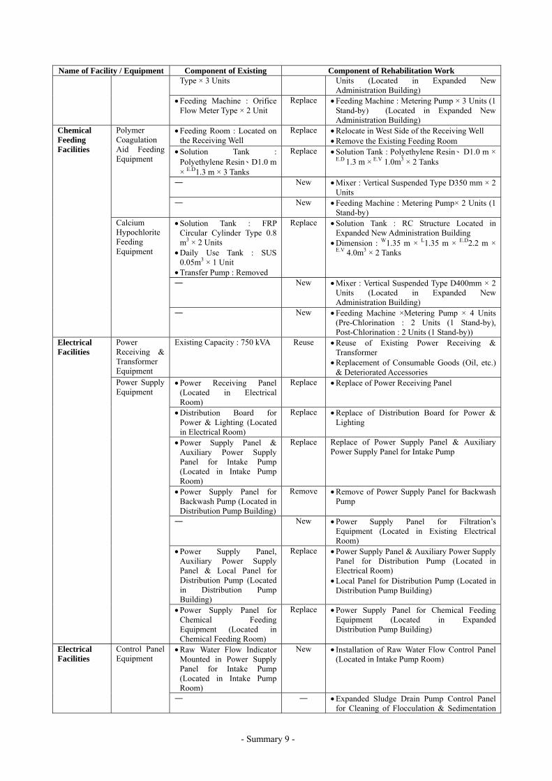
Components of Rehabilitation Work of Kaolieo Treatment Plant
Name of Facility / Equipment Component of Existing Component of Rehabilitation Work
Intake Structure
• Intake Tower Type Renovate • Replacement of Doors & Windows • Rust Removal & Painting of Handrails • Substitute Grating for Checked Plate of Pump
House Floor River Bank & River Bed Protection
• Upstream of Tower : Gabion Mattress Work & Soda Mattress Work
• Downstream of Tower : Gabion Mattress Work with Pipe Pile Anchor Work
Improve • Reinforcement of Existing River Bed Protection by Soda Mattress Work
• River Bank & River Bed Protection Area/Place to be constructed by Expanded Intake Structure included in Expansion Work
• Vertical Mixed Flow Pump : D250 mm × 7.65 m3/min × 19.5 m × 37 kW × 3 Units (1-Standby) - Located in Intake Tower
• Horizontal Single Suction Volute Pump : D200 mm × 4.5 m3/min × 40 m × 45 kW × 1 Unit – Located on Floating Dock
Replace • Submersible Pump : D250 mm × 7.7 m3/min × 20.5 m × 45 kW × 3 Units (1-Standby)
• Removal of Horizontal Single Suction Volute Pump including Valves & Piping with Floating Dock
Intake Pump
• D250 mm Check Valve • D250 mm Gate Valve
Replace • D250 mm Check Valve • D250 mm Short Body Type Electric
Motor-drive Butterfly Valve (Horizontal Type)
Intake Facilities
Crane Equipment
• 5 ton Electric Motor-drive Chain Block × 3 Units
Replace • 5 ton Electric Motor-drive Chain Hoist Crane (Traversing, Traveling, Hoisting) × 1 Unit

- Summary 6 -
Name of Facility / Equipment Component of Existing Component of Rehabilitation Work Maintenance Bridge
• Steel Truss Bridge with Wooden Plates
Renovate • Rust Removal & Painting • Replace Wooden Plates with Lightweight
Grating Raw Water Transmission Main
• Steel Pipe : D500 mm Repair • Rust Removal & Painting of Steel Pipe Raw Water Transmission Facilities
Flow Control Valve
• D500 mm × Manual Operate Type Butterfly Valve (Horizontal Type) × 1 Unit
Replace • D500 mm × Tooth-shaped Disc Type Butterfly Valve (Horizontal Type) × 2 Units (Electric Motor-drive Type × 1 Unit、Manual Type × 1 Unit)
Receiving Well (Mixing Well)
• RC Structure, 1 Basin, Detention Time = 1.6 min
Improve • Plug a Opening of Outlet Wall and Rebuild the Weir for Coagulation
Receiving Well & Mixing Well Facilities Flash Mixer • Vertical Suspended Type
Mixer × 1 Unit Locate in Receiving Well
Remove • Remove due to modification of the existing coagulation method (Gravitational Force Mixing by Weir Type)
• RC Structure, 4 Basins • Flocculation Type : Baffled
Channel Type • Detention Time = 37.8 min
(Except Outlet Zone)
Improve • Rebuild the Weir from the Existing Wooden Wall for Coagulation Aid
• Improvement of the Existing Baffled Channel Walls
• Plug 4-Opening of Outlet Wall and Rebuild the Weir for Prevention of Jet Flow
Flocculation Basin
• Inlet Valve : D400 mm × 2 Units
Replace • D400 mm Manual Operate Sluice Valve × 2 Units
• RC Structure、4 Basins • Sedimentation Type :
Conventional Type with Gravel Filter
• Detention Time = 2.0 hr (3.2 hr including Gravel Filter)
Improve • Installation of Intermediate Perforated Baffle Wall
• Remove Gravel Filter • Substitute Outlet Launders (Uni-flow Type) for
Gravel Filter • Replace Ladder • Rust Removal & Painting of Handrail
• Drain Valve : D150 mm × 2 Units (Located Outlet Channel)
Replace • D150 mm Manual Operate Sluice Valve × 2 Units
Sedimentation Basin
• Occurrence of Leakage from Structural Wall
Repair • Repair of Structural Wall’s Clacks
• Flocculation Basin : Drain Valve D250 mm × 4 Units
Not in Use
(Untreated)
• Installation of Steel Plate Slide Gate for Desludging – 11 Sets/Basin
• Substitute Steel Plate Slide Gate for Drain Valve
• Sedimentation Basin : Sludge Valve D300 mm × 4 Units
Replace • D300 mm Sluice Valve with Manual Operating Stand × 4 Units
Flocculation & Sedimentation Facilities
Desludging Equipment (Flocculation & Sedimentation Basin)
• Pressurized Water Supply System for Cleaning of Flocculation & Sedimentation Basin
Improve • Enhanced Desludging System for Sedimented Sludge : Pressurized Piping with Slit D250 mm × 4 Lots (Commonage Expanded Pressurized Raw Water System)
• Pressurized Cleaning Piping System for Flocculation & Sedimentation Basin : Commonage Expanded Raw Water Pumping System)
Filtration Facilities
Rapid Sand Filtration basin
• RC Structure、4 Basins • Filtration Type : Rapid Sand
Filtration – Surface wash & Backwash Water System
• Under drain System : Strainer Type
• Filtered Area = 45.1 m2/Basin (Dimension : W5.5 m × L8.2 m)
• Filtration Rate = 122 m/d • Backwash Rate = 0.60
m3/min/m2
• Surface wash Rate = 0.15
Improve • Filtration Type : Substitute Rapid Sand Filtration – Air Scouring Type same as Expansion for Existing – Surface wash & Backwash Water System
• Under drain System : Porous Plate Type • Filtered Area = 36.9 m2/Basin (Dimension :
W4.5 m × L8.2 m) • Filtration Rate = 149.1 m/d • Backwash Rate = 0.36 m3/min/m2 • Air Scouring Rate = 1.00 m3/min/m2 • Remove Wash Water Troughs • Rebuild Filtered Water Chamber, Air Scouring
Chamber & Wash Water Drain Chamber in
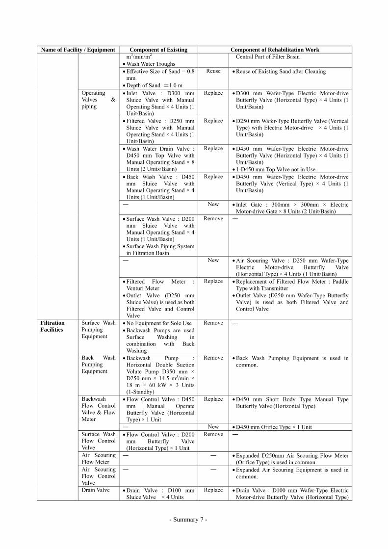
- Summary 7 -
Name of Facility / Equipment Component of Existing Component of Rehabilitation Work m3/min/m2
• Wash Water Troughs Central Part of Filter Basin
• Effective Size of Sand = 0.8 mm
• Depth of Sand =1.0 m
Reuse • Reuse of Existing Sand after Cleaning
• Inlet Valve : D300 mm Sluice Valve with Manual Operating Stand × 4 Units (1 Unit/Basin)
Replace • D300 mm Wafer-Type Electric Motor-drive Butterfly Valve (Horizontal Type) × 4 Units (1 Unit/Basin)
• Filtered Valve : D250 mm Sluice Valve with Manual Operating Stand × 4 Units (1 Unit/Basin)
Replace • D250 mm Wafer-Type Butterfly Valve (Vertical Type) with Electric Motor-drive × 4 Units (1 Unit/Basin)
• Wash Water Drain Valve : D450 mm Top Valve with Manual Operating Stand × 8 Units (2 Units/Basin)
Replace • D450 mm Wafer-Type Electric Motor-drive Butterfly Valve (Horizontal Type) × 4 Units (1 Unit/Basin)
• 1-D450 mm Top Valve not in Use • Back Wash Valve : D450
mm Sluice Valve with Manual Operating Stand × 4 Units (1 Unit/Basin)
Replace • D450 mm Wafer-Type Electric Motor-drive Butterfly Valve (Vertical Type) × 4 Units (1 Unit/Basin)
― New • Inlet Gate : 300mm × 300mm × Electric Motor-drive Gate × 8 Units (2 Unit/Basin)
• Surface Wash Valve : D200 mm Sluice Valve with Manual Operating Stand × 4 Units (1 Unit/Basin)
• Surface Wash Piping System in Filtration Basin
Remove ―
― New • Air Scouring Valve : D250 mm Wafer-Type Electric Motor-drive Butterfly Valve (Horizontal Type) × 4 Units (1 Unit/Basin)
Operating Valves & piping
• Filtered Flow Meter : Venturi Meter
• Outlet Valve (D250 mm Sluice Valve) is used as both Filtered Valve and Control Valve
Replace • Replacement of Filtered Flow Meter : Paddle Type with Transmitter
• Outlet Valve (D250 mm Wafer-Type Butterfly Valve) is used as both Filtered Valve and Control Valve
Surface Wash Pumping Equipment
• No Equipment for Sole Use • Backwash Pumps are used
Surface Washing in combination with Back Washing
Remove ―
Back Wash Pumping Equipment
• Backwash Pump : Horizontal Double Suction Volute Pump D350 mm × D250 mm × 14.5 m3/min × 18 m × 60 kW × 3 Units (1-Standby)
Remove • Back Wash Pumping Equipment is used in common.
• Flow Control Valve : D450 mm Manual Operate Butterfly Valve (Horizontal Type) × 1 Unit
Replace • D450 mm Short Body Type Manual Type Butterfly Valve (Horizontal Type)
Backwash Flow Control Valve & Flow Meter
― New • D450 mm Orifice Type × 1 Unit Surface Wash Flow Control Valve
• Flow Control Valve : D200 mm Butterfly Valve (Horizontal Type) × 1 Unit
Remove ―
Air Scouring Flow Meter
― ― • Expanded D250mm Air Scouring Flow Meter (Orifice Type) is used in common.
Air Scouring Flow Control Valve
― ― • Expanded Air Scouring Equipment is used in common.
Filtration Facilities
Drain Valve • Drain Valve : D100 mm Sluice Valve × 4 Units
Replace • Drain Valve : D100 mm Wafer-Type Electric Motor-drive Butterfly Valve (Horizontal Type)
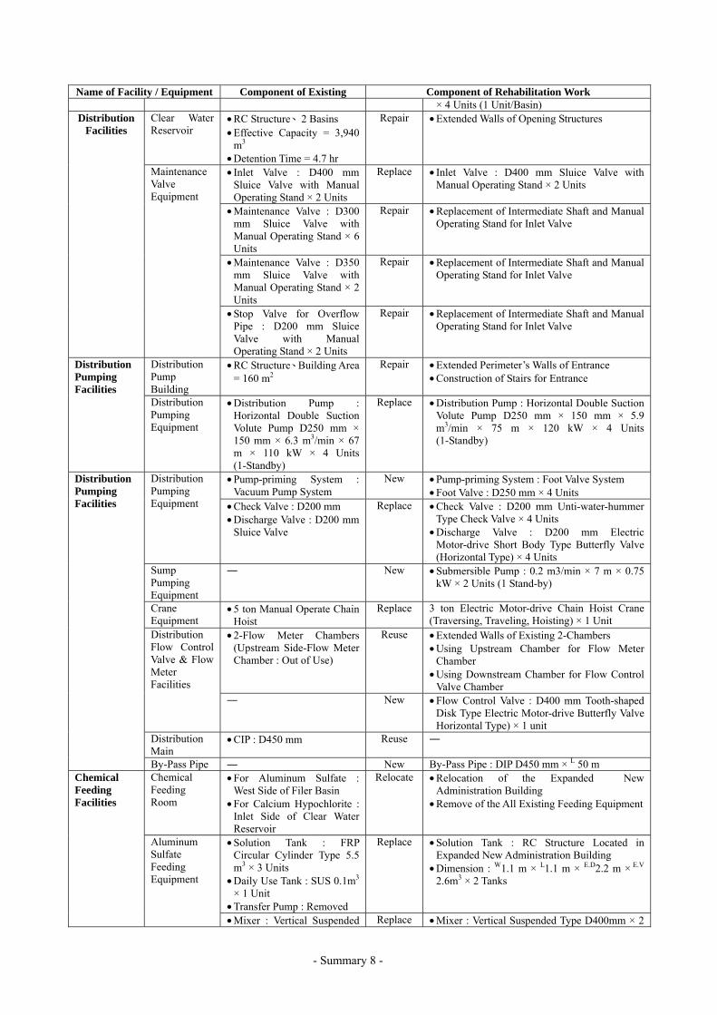
- Summary 8 -
Name of Facility / Equipment Component of Existing Component of Rehabilitation Work × 4 Units (1 Unit/Basin)
Clear Water Reservoir
• RC Structure、2 Basins • Effective Capacity = 3,940
m3 • Detention Time = 4.7 hr
Repair • Extended Walls of Opening Structures
• Inlet Valve : D400 mm Sluice Valve with Manual Operating Stand × 2 Units
Replace • Inlet Valve : D400 mm Sluice Valve with Manual Operating Stand × 2 Units
• Maintenance Valve : D300 mm Sluice Valve with Manual Operating Stand × 6 Units
Repair • Replacement of Intermediate Shaft and Manual Operating Stand for Inlet Valve
• Maintenance Valve : D350 mm Sluice Valve with Manual Operating Stand × 2 Units
Repair • Replacement of Intermediate Shaft and Manual Operating Stand for Inlet Valve
Distribution Facilities
Maintenance Valve Equipment
• Stop Valve for Overflow Pipe : D200 mm Sluice Valve with Manual Operating Stand × 2 Units
Repair • Replacement of Intermediate Shaft and Manual Operating Stand for Inlet Valve
Distribution Pump Building
• RC Structure、Building Area = 160 m2
Repair • Extended Perimeter’s Walls of Entrance • Construction of Stairs for Entrance
Distribution Pumping Facilities
Distribution Pumping Equipment
• Distribution Pump : Horizontal Double Suction Volute Pump D250 mm × 150 mm × 6.3 m3/min × 67 m × 110 kW × 4 Units (1-Standby)
Replace • Distribution Pump : Horizontal Double Suction Volute Pump D250 mm × 150 mm × 5.9 m3/min × 75 m × 120 kW × 4 Units (1-Standby)
• Pump-priming System : Vacuum Pump System
New • Pump-priming System : Foot Valve System • Foot Valve : D250 mm × 4 Units
Distribution Pumping Equipment • Check Valve : D200 mm
• Discharge Valve : D200 mm Sluice Valve
Replace • Check Valve : D200 mm Unti-water-hummer Type Check Valve × 4 Units
• Discharge Valve : D200 mm Electric Motor-drive Short Body Type Butterfly Valve (Horizontal Type) × 4 Units
Sump Pumping Equipment
― New • Submersible Pump : 0.2 m3/min × 7 m × 0.75 kW × 2 Units (1 Stand-by)
Crane Equipment
• 5 ton Manual Operate Chain Hoist
Replace 3 ton Electric Motor-drive Chain Hoist Crane (Traversing, Traveling, Hoisting) × 1 Unit
• 2-Flow Meter Chambers (Upstream Side-Flow Meter Chamber : Out of Use)
Reuse • Extended Walls of Existing 2-Chambers • Using Upstream Chamber for Flow Meter
Chamber • Using Downstream Chamber for Flow Control
Valve Chamber
Distribution Flow Control Valve & Flow Meter Facilities
― New • Flow Control Valve : D400 mm Tooth-shaped Disk Type Electric Motor-drive Butterfly Valve Horizontal Type) × 1 unit
Distribution Main
• CIP : D450 mm Reuse ―
Distribution Pumping Facilities
By-Pass Pipe ― New By-Pass Pipe : DIP D450 mm × L 50 m Chemical Feeding Room
• For Aluminum Sulfate : West Side of Filer Basin
• For Calcium Hypochlorite : Inlet Side of Clear Water Reservoir
Relocate • Relocation of the Expanded New Administration Building
• Remove of the All Existing Feeding Equipment
• Solution Tank : FRP Circular Cylinder Type 5.5 m3 × 3 Units
• Daily Use Tank : SUS 0.1m3 × 1 Unit
• Transfer Pump : Removed
Replace • Solution Tank : RC Structure Located in Expanded New Administration Building
• Dimension : W1.1 m × L1.1 m × E.D2.2 m × E.V 2.6m3 × 2 Tanks
Chemical Feeding Facilities
Aluminum Sulfate Feeding Equipment
• Mixer : Vertical Suspended Replace • Mixer : Vertical Suspended Type D400mm × 2
- Summary 9 -
Name of Facility / Equipment Component of Existing Component of Rehabilitation Work Type × 3 Units Units (Located in Expanded New
Administration Building) • Feeding Machine : Orifice
Flow Meter Type × 2 Unit Replace • Feeding Machine : Metering Pump × 3 Units (1
Stand-by) (Located in Expanded New Administration Building)
• Feeding Room : Located on the Receiving Well
Replace • Relocate in West Side of the Receiving Well • Remove the Existing Feeding Room
• Solution Tank : Polyethylene Resin、D1.0 m × E.D1.3 m × 3 Tanks
Replace • Solution Tank : Polyethylene Resin、D1.0 m × E.D 1.3 m × E.V 1.0m3 × 2 Tanks
― New • Mixer : Vertical Suspended Type D350 mm × 2 Units
Polymer Coagulation Aid Feeding Equipment
― New • Feeding Machine : Metering Pump× 2 Units (1 Stand-by)
• Solution Tank : FRP Circular Cylinder Type 0.8 m3 × 2 Units
• Daily Use Tank : SUS 0.05m3 × 1 Unit
• Transfer Pump : Removed
Replace • Solution Tank : RC Structure Located in Expanded New Administration Building
• Dimension : W1.35 m × L1.35 m × E.D2.2 m ×
E.V 4.0m3 × 2 Tanks
― New • Mixer : Vertical Suspended Type D400mm × 2 Units (Located in Expanded New Administration Building)
Chemical Feeding Facilities
Calcium Hypochlorite Feeding Equipment
― New • Feeding Machine ×Metering Pump × 4 Units (Pre-Chlorination : 2 Units (1 Stand-by), Post-Chlorination : 2 Units (1 Stand-by))
Power Receiving & Transformer Equipment
Existing Capacity : 750 kVA Reuse • Reuse of Existing Power Receiving & Transformer
• Replacement of Consumable Goods (Oil, etc.) & Deteriorated Accessories
• Power Receiving Panel(Located in Electrical Room)
Replace • Replace of Power Receiving Panel
• Distribution Board for Power & Lighting (Located in Electrical Room)
Replace • Replace of Distribution Board for Power & Lighting
• Power Supply Panel & Auxiliary Power Supply Panel for Intake Pump (Located in Intake Pump Room)
Replace Replace of Power Supply Panel & Auxiliary Power Supply Panel for Intake Pump
• Power Supply Panel for Backwash Pump (Located in Distribution Pump Building)
Remove • Remove of Power Supply Panel for Backwash Pump
― New • Power Supply Panel for Filtration’s Equipment (Located in Existing Electrical Room)
• Power Supply Panel, Auxiliary Power Supply Panel & Local Panel for Distribution Pump (Located in Distribution Pump Building)
Replace • Power Supply Panel & Auxiliary Power Supply Panel for Distribution Pump (Located in Electrical Room)
• Local Panel for Distribution Pump (Located in Distribution Pump Building)
Electrical Facilities
Power Supply Equipment
• Power Supply Panel for Chemical Feeding Equipment (Located in Chemical Feeding Room)
Replace • Power Supply Panel for Chemical Feeding Equipment (Located in Expanded Distribution Pump Building)
• Raw Water Flow Indicator Mounted in Power Supply Panel for Intake Pump (Located in Intake Pump Room)
New • Installation of Raw Water Flow Control Panel (Located in Intake Pump Room)
Electrical Facilities
Control Panel Equipment
― ― • Expanded Sludge Drain Pump Control Panel for Cleaning of Flocculation & Sedimentation

- Summary 10 -
Name of Facility / Equipment Component of Existing Component of Rehabilitation Work Basin is used in common.
― New • Filtration’s Control Panel (Located on Filtration Gallery)
• Control Panel for Chemical Feeding Equipment (Located in Chemical Feeding Room)
Replace • Control Panel for Chemical Feeding Equipment (Located in Expanded New Administration Building)
• Distribution Flow Indicator (Located in Distribution Pump Building)
New • Distribution’s Control Panel (Located in Distribution Flow Meter Chamber)
• Central Control Panel (Located in Chemical Feeding Room)
Remove ―
Air Conditioning Facilities
― New • Installation of Air Conditioning Facilities(Located in Existing Electrical Room)
Inter-Communication System
― New • Inter-communication Equipment (Located in Intake Tower, Polymer Feeding Room, Filter’s Operation Gallery, Distribution Pump Building & Electrical Room)
Lightning Protection Equipment
• Lightning Rod Equipment (Located in Intake Tower, Distribution Pump Building & Warehouse)
Replace • Lightning Rod Equipment (Located in Intake Tower, Filter Basin, Distribution Pump Building & Warehouse)
― New • Central Supervising Panel & Instrumentation Panel (Located in Operation Room of Expanded New Administration Building)
― New • Raw Water Level Meter : Ultrasonic Type - Water Level for Raw Water Intake Pumping Well (Mekong River)
Instrumentation Facilities
Instrumentation Equipment
• Raw Water Flow Meter : Orifice Type
Replace • Replacement of Raw Water Flow Meter : Ultrasonic Type (Non-Retractable Type)
• Filtration Resistance Meter : Direct Reading Type
Replace • Replacement of Filtration Resistance Meter : Electronic Type
• Filtered Flow Meter : Venturi Meter
Replace • Replacement of Filtered Flow Meter : Paddle Type with Transmitter
― New • Total Filtered Flow Meter : Ultrasonic Type (Non-Retractable Type)
• Clear Water Level Meter (Located in Distribution Pump Building)
Replace • Replacement of Clear Water Level Meter : Ultrasonic Type
• Distribution Flow Meter : Venturi Type
Remove ―
• Distribution Flow Meter : Orifice Type
Replace • Replacement of Distribution Flow Meter : Ultrasonic Type (Non-Retractable Type)
― New • Distribution Line Pressure Meter : Electronic Type
Instrumentation Facilities
Instrumentation Equipment
― New • Chemical Solution Tank Level Meter : Electrode Type
Administration Building • Administration Building : Timber Structure
Remove • Expanded New Administration Building is used in common.
Laboratory • Located in Administration Building
Remove • Expanded New Laboratory is used in common.
• Drain System for Flocculation & Sedimentation
Replace • Replacement of Drain Pipe : D300 mm → D400 mm D350 mm → D400 mm
• Drain System for Filter’s Washing
Reuse ―
Drain Piping & Chamber Facilities
• Combined Drain System Both Drain System the above
New • Construction of Drain Chamber for Drainage Pump
• Dimension : W1.5 m × L3.0 m × D4.47 m
Drain System in Treatment Plant
Sludge Drain Pumping
• Drainage Pump : Engine Drive Self-contained Type
Replace • Drainage Pump : Detachable Submersible Motor Pump D400 mm × 18 m3/min × 5 m ×

- Summary 11 -
Name of Facility / Equipment Component of Existing Component of Rehabilitation Work Equipment Pump × 1 Unit 30 kW × 1 Unit Sump Pumping Equipment in Substation
― New • Submersible Pump : 0.2 m3/min × 7 m × 0.75 kW × 2 Units (1 Stand-by)
Landscaping and Others • Existing Ground Level :
+170.50 m~+172.00 m Improve • Site Preparation, Embankment (Ground
Leveling +172.20 m), Roads, Lighting, Gate & Fence, others
Components of Improvement Work of Chinaimo Treatment Plant
Name of Facility / Equipment Component of Improvement Work
RC Structure、Effective Capacity = 7,500 m3、Detention Time =3.5 hr, Dimension : W20.0 m × L70.0 m × D3.76 m × E.D2.68 m × 2 Basins Inlet Valve : D1,100mm Short Body Butterfly Valve × 2 Units Overflow Pipe : D600 mm Connecting Valve : D700mm Short Body Butterfly Valve with Manual Operating Stand × 2 Units
Distribution Facility
Clear Water Reservoir
Ventilation Device : 1 Lot Distribution Pump Building
RC Structure、 Building Area = 200m2 (Dimension : W20.0 m × L10.0 m) Distribution Pump : Horizontal Double Suction Volute Pump D300 mm x D200 mm × 13.1 m3/min × 71 m × 220 kW × 4 Units(1-Standby) Foot Valve : D300mm × 4 Units Suction Valve : D300 mm Short Body Type Butterfly Valve (Manual Operate) × 4 Units
Distribution Pumping Equipment
Check Valve : D300 mm Unti-water-hummer Type × 4 Units Delivery Valve : D300 mm Short Body Type Electric Motor – drive Butterfly Valve
(Horizontal Type) × 4 Units Crane Equipment
5 ton Electric Motor-drive Chain Hoist Crane (Traversing, Traveling, Hoisting) × 1 Unit
Sump Pumping Equipment
Submersible Pump : 0.2 m3/min × 7 m × 0.75 kW × 2 Unit (1 Stannd-by)
Flow Meter Chamber & Flow Control Valve Chamber Flow Meter & Flow Control Valve Facility
Flow Control Valve : D600 mm Tooth–shaped Disk Type Electric Motor-drive Butterfly Valve (Horizontal Type) × 1 Unit
Distribution Piping
DIP : D700 mm × L30 m DIP : D600 mm × L49 m DIP : D200 mm × L40 m DIP : D700 mm × L11 m for By-Pass Line
Distribution Pumping Facilities
Other Valves Connecting Valve : D700 mm Horizontal Type Butterfly Valve × 1 Unit Connecting Valve : D200 mm Horizontal Type Butterfly Valve × 1 Unit
Unti-Water-Hummer Equipment
Air Chamber : Steel Fabrication - Vertical Type Air Capacity : 4.5 m3 (Dimension : D2.4 m × L3.0 m) Air Compressor : Belt-drive Type 665 Nl/min × 0.69 MPa × 5.5 kw × 2 Units (1-Standby)
Transmission Piping
DIP : D700 mm × L127 m DIP : D300 mm × L 82 m for the Salakham Reservoir
Transmission Facilities
Other Valves Connecting Valve : D700 mm Horizontal Type Butterfly Valve × 1 Unit Power Receiving & Transformer Equip.
Capacity of Improvement : Replace : 1,000 kVA × 1 Unit Removal of Existing Transformer : 1,000 kVA × 2 Units
Power Supply Equipment
Power Receiving Panel Power Supply Panel & Auxiliary Power Supply Panel for Distribution Pump
Lightning Protection Equipment
Lightning Rod Equipment (Located in Distribution Pump Building)
Intercommunication System
Intercommunication Equipment (Located in Distribution Pump Building)
Electrical Facilities
Air Conditioning Facilities
Installation of Air Conditioning Facilities (Located in Electrical Room of Distribution Pumping Building)
Instrumentati Instrumentation Central Supervising Panel & Instrumentation Panel including the Existing (Located in

- Summary 12 -
Name of Facility / Equipment Component of Improvement Work Operation Room of the Existing Administration Building) Clear Water Reservoir Level Meter : Ultrasonic Type Distribution Line Piesometer : Electronic Type Distribution Flow Meter : Ultrasonic Type (Non-Retractable Type)
on Facilities Equipment
Transmission Flow Meter : Replacement of the Existing Ultrasonic Type (Non-Retractable Type) for the Salakham Reservoir
Landscaping and Others Site Preparation, Embankment, Roads, Lighting, Others
Components of Rehabilitation Work of Km6 Booster Pumping Station
Name of Facility / Equipment Component of Improvement Work
Replace Distribution Pump : Horizontal Single Suction Volute Pump D150 mm × D125 mm × 4.2 m3/min × 28 m × 30 kW × 3 Units (1 Stand-by)
Replace Check Valve : D150 mm Unti-water-hummer Type × 3 Units Discharge Valve : D150 mm Short Body Type Electric Motor-drive Butterfly Valve (Horizontal Type) × 3 Unit
Distribution Facilities
Distribution Pumping Equipment
Replace Flow Meter : D150 mm Orifice Type (Direct Reading Method) × 1 Unit Power Receiving & Transformer Equipment
New Capacity of Low Voltage Power Receiving : 100 kVA (Receive Power Transmission Line [380 V, 3-Phase, 4-Wirw] from EDL)
Electrical Facilities
Power Receiving Equipment
New Low Voltage Power Receiving Panel Low Voltage Distribution Panel
Control Panel Equipment
Replace Control Panel for Distribution Pump Instrumentation Facilities
Instrumentation Equipment
Replace Distribution Line Pressure Meter : Electronic Type × 1 Unit
Landscaping and Others Improve Site Preparation, Embankment, Road, Lighting, Gate & Fence, Others
Required Pipe Specifications
Pipe Material and Diameter (mm) *Pipe Length(m) Duplication of No.1 road
project (m) DCIPφ700 1,220 340 DCIPφ600 1,580 1,560 DCIPφ400 4,685 40 PVCφ150 5,150 750
Total 12,635 2,690
* Pipe length includes duplicated alignment with “The project for the improvement of the Vientiane No.1 Road
(hereinafter referred to as No.1 road project)”.
Implementation of this project, in the case of Japan’s Grant Aid Scheme, will require 36.5 months, including 5.0
months for detailed design. The cost is estimated as follows;
Case 1
When the construction of duplication part will be implemented after No.1 road project, the cost is estimated to be
2,955 Million Yen (2,916 Million Yen by Japanese side and 39 Million Yen by Lao PDR side).

- Summary 13 -
Case 2
When the construction of duplication part will be implemented before No.1 road project, the cost is estimated to
be 2,911 Million Yen (2,872 Million Yen by Japanese side and 39 Million Yen by Lao PDR side).
The expected benefits from the project are as follows;
(1) By the expansion of Kaolieo Treatment Plant to a capacity of 40,000 m3/day, it is expected to improve the
current water supply conditions; increase of the water supply ratio from 38.5 % (2003, before project) to 47.0%
(2010, after project).
(2) By the rehabilitation of the existing Kaolieo Treatment Plant to achieve its 20,000 m3/day capacity by the
renewal of old electrical and mechanical equipment and constructions, it is expected to assure the stable water
supply in Vientiane City.
(3) By the improvement of the existing Chinaimo Treatment Plant including separation of the
transmission/distribution pipelines, construction of a new distribution reservoir (with a capacity of 7,500 m3) and
construction of a new pumping station, it is expected to assure the stable water supply which corresponds to the
demand change throughout the day.
This project will bring many benefits listed above, and contribute to improve BHN for local residence. Therefore,
it is appropriate to use Japan’s Grant Aid Scheme for the part of this project. In addition, organizations of Lao
PDR side are well enough to run this project. However, following actions and/or measures should be considered
for sustainable and efficient project operation and management.
1. Procurement and Installation of Small Size Distribution Pipes and House Connections
2. Required Staff Assignment for Adequate Operation and Maintenance

Basic Design Study Report on
The Project for the Vientiane Water Supply Development in
Lao People’s Democratic Republic
Preface Letter of Transmittal Location Map / Project Location Map List of Figures & Tables Abbreviations Summary
Table of Contents Chapter 1 Background of the Project ------------------------------------------------------------------------------- 1-1
Chapter 2 Contents of the Project------------------------------------------------------------------------------------ 2-1 2-1 Basic Concept of the Project--------------------------------------------------------------------------- 2-1 2-2 Basic Design of the Requested Japanese Assistance ----------------------------------------------- 2-3
2-2-1 Design Policy ---------------------------------------------------------------------------------- 2-3 2-2-1-1 Basic Design ----------------------------------------------------------------------- 2-3 2-2-1-2 Design Policy for Natural Conditions ------------------------------------------ 2-4 2-2-1-3 Design Policy for Socio-economic Conditions ------------------------------- 2-5 2-2-1-4 Design Policy for Using Local Contractors ----------------------------------- 2-5 2-2-1-5 Design Policy for Capacity of GOL to undertake operation and
Maintenance ----------------------------------------------------------------------- 2-6 2-2-1-6 Design Policy for Grade of Facilities and Equipment ----------------------- 2-6 2-2-1-7 Design Policy for Construction Method and Schedule ---------------------- 2-6
2-2-2 Basic Plan -------------------------------------------------------------------------------------- 2-6 2-2-2-1 Future Water Demand ------------------------------------------------------------ 2-6 2-2-2-2 Basic Design Conditions --------------------------------------------------------2-10 2-2-2-3 Expansion of Kaolieo Treatment Plant----------------------------------------2-11 2-2-2-4 Rehabilitation of Kaolieo Treatment Plant -----------------------------------2-26 2-2-2-5 Improvement of Chinaimo Treatment Plant----------------------------------2-38 2-2-2-6 Rehabilitation of Km6 Booster Pumping Station----------------------------2-43 2-2-2-7 Improvement of Water Transmission and Distribution System------------2-45
2-2-3 Basic Design Drawings ---------------------------------------------------------------------2-71 2-2-4 Implementation Plan----------------------------------------------------------------------- 2-100
2-2-4-1 Implementation Policy -------------------------------------------------------- 2-100 2-2-4-2 Implementation Conditions --------------------------------------------------- 2-101 2-2-4-3 Scope of Works----------------------------------------------------------------- 2-102 2-2-4-4 Consultant Supervision-------------------------------------------------------- 2-103 2-2-4-5 Procurement Plan -------------------------------------------------------------- 2-104 2-2-4-6 Quality Control Plan----------------------------------------------------------- 2-107 2-2-4-7 Implementation Schedule ----------------------------------------------------- 2-109
2-3 Obligations of Recipient Country ------------------------------------------------------------------ 2-111 2-3-1 Land Acquisition --------------------------------------------------------------------------- 2-111 2-3-2 Disposal of Equipment that is removed during the Rehabilitation Work----------- 2-111 2-3-3 Additional Power Supply to Treatment Plant and Pumping Station ---------------- 2-111 2-3-4 Procurement and Installation of Small Size Distribution Pipes and
House Connections ------------------------------------------------------------------------- 2-112 2-3-5 Required Staff Assignment for Adequate Operation and Maintenance------------- 2-112 2-3-6 Issuing of Construction Permission ----------------------------------------------------- 2-112

2-3-7 Others ---------------------------------------------------------------------------------------- 2-112 2-3-8 Suggestions Concerning Dongmark Khay Project ------------------------------------ 2-113
2-4 Project Operation Plan------------------------------------------------------------------------------- 2-113 2-4-1 Operation and Maintenance after Completion of the Project ------------------------ 2-113 2-4-2 Operation and Maintenance Capacity of the NPVC ---------------------------------- 2-114 2-4-3 Status of Leakage and Water Tariff Collection----------------------------------------- 2-115
2-4-3-1 Status of Leakage -------------------------------------------------------------- 2-115 2-4-3-2 Status of Tariff Collection----------------------------------------------------- 2-116
2-4-4 Cost Estimates for the Project ------------------------------------------------------------ 2-117 2-4-4-1 Project Costs -------------------------------------------------------------------- 2-117 2-4-4-2 Operation and Maintenance Costs ------------------------------------------- 2-119
2-4-4-2-1 Financial Situation of the NPVC ------------------------------ 2-119 2-4-4-2-2 Operation and Maintenance Costs ---------------------------- 2-123
2-5 Other Relevant Issues-------------------------------------------------------------------------------- 2-123 Chapter 3 Project Evaluation and Recommendations ----------------------------------------------------------- 3-1
3-1 Project Effect--------------------------------------------------------------------------------------------- 3-1 3-2 Recommendations--------------------------------------------------------------------------------------- 3-2
Appendices
1 Member List of the Study Team ------------------------------------------------------------------------ A-1 2 Study Schedule -------------------------------------------------------------------------------------------- A-3 3 List of Parties Concerned in the Recipient Country ------------------------------------------------- A-6 4 Minutes of Discussions ---------------------------------------------------------------------------------- A-9 5 Cost Estimation Borne by the Recipient Country ---------------------------------------------------A-27 6 References ------------------------------------------------------------------------------------------------A-28

Chapter 1
Background of the Project

1 - 1
Chapter 1 Background of the Project
The Government of Lao People’s Democratic Republic (GOL) is implementing their fifth “Five Year National
Development Plan (2001 to 2005)”. The GOL has also formulated a Long Term Development Plan which has a
target year of 2020. In the Long Term Development Plan, development of social infrastructure such as water and
sewerage are given the highest priority. The key targets of this plan include development of the water supply
sector to achieve a national average water supply service ratio of 90 %, with a ratio of 100 % in urban areas and
80 % in smaller scale towns.
Based on the above situation, GOL requested Japan International Cooperation Agency (JICA) to conduct the
social development study titled “The Study on Vientiane Water Supply Development Project (M/P, F/S)”. As a
result of the study, it is found that currently water demand in Vientiane Capital City is 100,000 m3/day (80,000
m3/day and 20,000 m3/day from Chinaimo and Kaolieo Treatment Plants respectively), which is in excess of the
water supply capacity, and estimated that by the year 2007, water demand will exceed water supply capacity by
approximately 40,000 m3/day.
After the social development study, GOL requested Japanese Grant Aid for the Vientiane Water Supply
Development Project. The following components are planned to achieve the project purpose:
• expansion of the existing water treatment plant;
• rehabilitation of the existing water treatment plant to realize its designed capacity;
• improvement of transmission and distribution system by improving the existing water treatment plant and by
rehabilitating the existing booster pumping station; and
• installation of transmission and distribution mains.

1 - 2
Figure 1-1 Location Map of Dongmark Khay Project
P
Kaolieo Treatment PlantProduction Capacity : 60,000m3/day
Existing : 20,000m3/dayExpansion : 40,000m3/day
Chinaimo Treatment PlantProduction Capacity : 80,000m3/day
Improvement : Separation ofTransmission and Distribution System
including Expansion of Reservoir,Distribution Pumping Facilities and
Transmission Pipeline
Salakham Elevated Tank
Dongdok Elevated TankNongteng Ground
Reservoir
Km6 Booster Pumping StationTransmission to Dongdok Reservoir
Distribution to North Area from Km6
Phonegtong Elevated Tank Xamkhe Elevated Tank
Phonegkheng Elevated Tank
Phonethane Elevated Tank
Nongteng BoosterPumping Station
Naxaythong Elevated tank
Km12 Booster PumpingStation
Existing IrrigationFacility
Intake Pump
Existing IrrigationFacility
Raw Water Canal
Existing IrrigationFacility
Regulation Pond
Dongmark Kai Project by NPNLDongmark Kai Treatment Plant
Production Capacity : 20,000m3/day
Mekong River
Nam NgumRiver
0 6km42
PlannedIndustrial Area
200
100
250450
400
Existing Irrigation FacilitiesP
Requested Scope for BasicDesign Study by Lao PDR
Existing Water SupplyFacilities
Treatment Plant byDongmark Khay Project
:
:
:
:
:
Transmission Pipe byDongmark Khay ProjectDistribution Pipe byDongmark Khay Project
:

Chapter 2
Contents of the Project
2 - 1
Chapter 2 Contents of the Project
2-1 Basic Concept of the Project
The GOL is implementing their fifth “Five Year National Development Plan (2001 to 2005)”. The GOL has also
formulated a Long Term Development Plan which has a target year of 2020. In the Long Term Development
Plan, development of social infrastructure such as water and sewerage are given the highest priority.
Based on these two plans (the National Development Plan and the Long Term Development Plan), the Ministry of
Communication, Transport, Post and Construction (MCTCP) prepared the “Development Plan for Communication,
Transport, Post and Construction, Year 1996 – 2020”. The key targets of this plan include development of the
water supply sector to achieve a national average water supply service ratio of 90 %, with a ratio of 100 % in
urban areas and 80 % in smaller scale towns.
In September 1999, the prime ministerial office issued the prime ministerial decree “Prime Ministerial Decision
on Management and Development of Water Supply Sector (No.37)”. The decree stated that a water supply
service ratio in urban areas of 80 % should be achieved as soon as possible and that Vientiane (the nation’s capital
city) should be assigned the highest priority for water supply sector development.
Due to financial and budgetary constraints, progress of development for the water supply sector has been delayed
and is therefore behind the targets set out in the development plans and stated in the above mentioned above.
Currently water demand in Vientiane Capital City is 100,000 m3/day (80,000 m3/day and 20,000 m3/day from
Chinaimo and Kaolieo Treatment Plants respectively), which is in excess of the water supply capacity. It is
estimated that by the year 2007, water demand will exceed water supply capacity by approximately 40,000
m3/day.
The goals of the project are to mitigate water shortages in Vientiane and to establish adequate water transmission
and distribution systems. It is proposed to achieve these goals by expanding the existing Kaolieo Water
Treatment Pant by an additional 40,000 m3/day and by improving the existing Chinaimo Water Treatment Plant
and transmission/distribution system.
The field investigation component of the Basic Design Study was conducted from 3 July 2004 to 6 August 2004.
The basic design work was carried out in Japan following the field investigation.
After the Study Team had returned to Japan to undertake the design work, the GOL informed the GOJ that the
GOL intended to implement an additional water supply improvement project called the “Dongmark Khay Project”.
This project had not been included in the previous social development study (M/P, F/S) and therefore the Study
Team had not undertaken the required investigations during their July/August trip.

2 - 2
The Scope of the Dongmark Khay Project includes:
• installation of an additional intake pump at Namgum River;
• construction of a new water treatment plant at Dongmark Khay, with a capacity of 20,000 m3/day; and
• installation of a transmission pipeline from the new treatment plant to the Phonetong elevated tank via
Dongdok.
The proposed Dongmark Khay water treatment plant will be located in the northern part of the city. As such, it
could affect the scope of Japan’s Grant Aid project. The Study Team therefore needed to confirm the details of
the Dongmark Khay Project. A second field investigation was conducted from 22 February 2005 to 6 March
2005. The results of this second field investigation confirmed that water from the Dongmark Khay treatment
plant would be supplied to the northern part of the City.
The previous master plan (M/P) and feasibility study (F/S) identified that the following improvements would
secure adequate water transmission/distribution to the northern part of the city:
• improvement of the Chinaimo Treatment Plant;
• rehabilitation of the Km6 Booster Pumping Station;
• installation of the transmission pipe to the Km6 Booster Pumping Station; and
• installation of the distribution pipe from the Km6 Booster Pumping Station.
As mentioned above, the GOL now plans to supply the northern part of the city from the Dongmark Khay
treatment plant. Therefore, the scope of Japan’s Grant Aid project was reviewed and modified to be consistent
with the Dongmark Khay Project planned by the GOL.
The following components are planned to achieve the project purpose:
• expansion of the existing water treatment plant;
• rehabilitation of the existing water treatment plant to realize its designed capacity;
• improvement of transmission and distribution system by improving the existing water treatment plant and by
rehabilitating the existing booster pumping station; and
• installation of transmission and distribution mains.
The proposed water supply system for this current project will be able to meet the year 2007 predicted water
demand. If the Dongmark Khay Project is implemented by the GOL, the total supply capacity will be 160,000
m3/day, which will be sufficient to meet the total water demand in 2010.
2 - 3
Considering the project purpose and the proposed Dongmark Khay Project mentioned above, the scope of Japan’s
Grant Aid Project is:
• expansion of Kaolieo Treatment Plant to a capacity of 40,000 m3/day;
• rehabilitation of the existing Kaolieo Treatment Plant to achieve its 20,000 m3/day capacity;
• improvement of the existing Chinaimo Treatment Plant including separation of the transmission/distribution
pipelines, construction of a new distribution reservoir (with a capacity of 7,500 m3) and construction of a
new pumping station;
• rehabilitation of the existing Km6 booster pumping station; and
• installation of transmission (approximately 0.72km) and distribution (approximately 11.92km) mains.
The location of the Dongmark Khay Project is shown on Figure 1-1. As shown on the figure, the water source
for the water treatment plant is an irrigation pond which currently receives water that is pumped from the
Namgum River. According to the GOL’s plan, one additional intake pump will be installed at the Namgum River.
The additional water will be conveyed to the irrigation pond through the existing irrigation canal.
The proposed capacity of the water treatment plant will be 20,000 m3/day. The water will be delivered, through
a proposed transmission pipeline, to the Phonetong elevated tank via Dongdok. As well as transmitting water to
the city, water will also be supplied to the Thangone area (in the far north) and the planned industrial estate.
The quantity of water supplied/transmitted for each area will be as follows:
North Thangone Area: 3,000 m3/day
Planned Industrial Area: 5,000 m3/day
Existing Service Area: 12,000 m3/day
(Phonetong via Dongdok)
Total 20,000 m3/day
The water allocations mentioned above were discussed by the GOL and the GOJ. Minutes of Discussion were
mutually signed on 1 March 2005. During these discussions, both the GOL and the GOJ agreed to review the
scope of Japan’s Grant Aid project with consideration of the Dongmark Khay project.
2-2 Basic Design of the Requested Japanese Assistance
2-2-1 Design Policy
2-2-1-1 Basic Design

2 - 4
The Basic Design was conducted in accordance with the principles listed below:
• The GOL requested that the Project be implemented based on the results of a social development study
(feasibility study) titled “The Study on Vientiane Water Supply Development Project” which was completed
by JICA in January 2004. Any changes to the Project context since that study were investigated, quantified
and the project scope was appropriately modified. These changes related to the national sector development
plan, social changes, population growth, increased per capita water demand etc.
• The most effective and efficient plan for expansion, rehabilitation, and improvement of treatment plants was
formulated to mitigate the water shortage situation in Vientiane.
• Consistency in scope was maintained between Japan’s Grant Aid project and the GOL Dongmark Khay
project.
• The design assumed that the Dongmark Khay project will be implemented by the GOL and that the
transmission/distribution system in the service area of the Dongmark Khay treatment plant will be developed
by the GOL.
• It was assumed that the GOL will coordinate input from the French Development Agency (AFD) when
undertaking the Dongmark Khay project.
2-2-1-2 Design Policy for Natural Conditions
Lao PDR has a tropical monsoon climate with a clearly distinguished wet season (May to October) and dry season
(November to April). Annual precipitation is about 1,700 mm and the maximum monthly precipitation is 350
mm and occurs in August. Precipitation during the dry season is very low. Figure 2-1 shows monthly
temperature and Figure 2-2 shows monthly precipitation compared with the water level in the Mekong River.
Figure 2-1 Monthly Temperature in Vientiane
05
10152025303540
1 2 3 4 5 6 7 8 9 10 11 12
Month
Tem
pera
ture
(℃)
Maximum Minimum
Source:Statistical Yearbook 2001, NSC

2 - 5
Figure2-2 Monthly Precipitation and Water Level of the Mekong River in Vientiane
(average from 1991~2003)
154.0
156.0
158.0
160.0
162.0
164.0
166.0
168.0
170.0
Jan Feb Mar Apr May Jun Jul Aug Sep Oct Nov Dec
Month
Wat
er L
evel
of t
he M
ekon
g R
iver
(m)
0.0
50.0
100.0
150.0
200.0
250.0
300.0
350.0
400.0
Prec
ipita
tion
(mm
/mon
th)
Precipitation Average Maximum Minimum
Source:Internal Waterway Department
As shown on the above figure, the water level in the Mekong River is low from December to April. This period
of low water level would be the most appropriate time to schedule construction work that needs to occur on the
river bank (such as intake facilities).
2-2-1-3 Design Policy for Socio-economic Conditions
There will be no significant adverse socio-economic impacts associated with the project provided that special care
is exercised during the installation of the pipelines that will be located along high traffic volume roads or roads
that are lined by many houses/shops .
In these road side locations, excavation of the trenches to accommodate the proposed pipelines could interfere
with the traffic movement and access to the houses/shops. To mitigate these impacts, the design will consider
using restrain joints that can withstand the force associated with pulling the pipeline out. This would allow for
quicker backfilling of the trench after pipe installation as compared to the more traditional use of concrete thrust
blocks. Concrete blocks require several days to cure before backfilling of the trench can occur.
2-2-1-4 Design Policy for Using Local Contractors
It is understood that there are sufficient, appropriately qualified and experienced local contractors available. Many
infrastructure construction development works have been implemented in Lao over the past few years with

2 - 6
funding from various donors. These projects have used local contractors and the projects have been successfully
completed. Therefore, the project proposal assumes that local contractors will be engaged to undertake the
construction works.
Recent examples of similar infrastructure work include the expansion of the Chinaimo Treatment Plant in
Vientiane in 1998 and the upgrade of the Nake Treatment Plant in Savannakhet in 2003, both funded by Japan’s
Grant Aid. Through both of these projects, local contractors demonstrated their experience constructing water
tight structures. Therefore, it is proposed that local contractors can be used to implement this current project.
2-2-1-5 Design Policy for Capacity of GOL to undertake Operation and Maintenance
There are problems at Kaolieo Treatment Plant due to old and deteriorated equipment, however operation and
maintenance levels at the Kaolieo and Chinaimo Treatment Plants were evaluated by the Study Team to be
adequate. This was indicated by the quality of the treated water from both the Kaolieo and Chinaimo treatment
plants meeting the World Health Organization (WHO) water quality guidelines for drinking water.
It can therefore be assumed that applying a similar level of water treatment technology as is used at the Kaolieo
and Chinaimo treatment plants to the expanded or improved plants, will be sustainable in terms of the NPVC
operation and maintenance capacity, provided the necessary training is implemented prior to the commencement
of the plants’ operation.
2-2-1-6 Design Policy for Grade of Facilities and Equipment
The grade of facilities and equipment being used in the Project should be selected to suit the capacity of the GOL,
as mentioned above (section 2-1-5). To reduce the operation and maintenance requirements, the treatment plants
will be designed as gravity flow systems wherever possible (instead of mechanical/pump systems). Also, the
plant control systems will be manually operated with on/off switches rather than a black-box system which relies
on automated computer controls.
2-2-1-7 Design Policy for Construction Method and Schedule
This is a relatively simple design project, therefore special or very advanced construction methods will not be
required for the construction schedule, which should be carefully planned so that the intake facilities are
constructed during the period of low water levels in Mekong River.
2-2-2 Basic Plan
2-2-2-1 Future Water Demand

2 - 7
Predicted population growth is one of the most significant factors to consider when planning for future water
demand. The Lao PDR has provided information, which indicates that the population in Vientiane has increased
rapidly over recent years. To confirm the Lao PDR population growth predictions, Vientiane population data for
2003 was obtained from National Statistics Center (NSC). This data indicated that the population of Vientiane in
2003 was 637,041 people. The previous JICA M/P & F/S predicted that the population in 2003 for Vientiane
would be 651,850, which is almost the same as the actual measured figure (the difference between the predicted
and the actual population was only two percent). Therefore the population predictions presented in the previous
JICA study can be assumed to be adequate.
The city of Vientiane is divided into nine districts. Of these, seven are included (or partially included) within the
water service area. Table 2-1 shows the actual measured NSC 2003 population data for these seven districts
compared with the population figures that were predicted by the previous JICA M/P & F/S.
Table2-1 Population of Seven Districts in Vientiane (Year 2003)
District Forecasted by the JICA Study Data from NSC
1 Chanthabuli 68,225 64,7132 Sikhottabong 86,033 93,5613 Saysettha 90,572 87,6514 Sisattanak 62,600 62,8425 Naxaithong 58,021 54,9786 Xaythany 135,305 134,1397 Hadxaifong 80,448 73,233
Total 581,204 571,117
The predicted increase in the number of houses connected to the water supply system is another significant factor
to consider when planning for future water demand. The previous JICA M/P & F/S estimated that there would
be 45,770 house connections in 2003. The actual number of house connections (as reported by the NPVC)
during 2003 was 46,314. Comparing these two figures, it is clear that the JICA study predictions were relatively
accurate.
The above discussion confirms the accuracy of the population increase predictions made by the previous JICA
M/P & F/S. Therefore, it can be assumed that the future water demand that was predicted by the JICA study can
be applied to this Basic Design Study.
Table 2-2 shows future population, service ratio, per capita consumption, unaccounted for water (UFW), and
water demand which were predicted by the previous JICA M/P & F/S. The figures in Table 2-2 were applied to
this Basic Design Study.

2 - 8
Table2-2 Future Water Demand Year 2003 2004 2005 2006 2007 2008 2009 2010
Total Population in Vientiane (person) 651,850 669,467 687,084 707,300 727,516 747,732 767,949 788,165Served Population (person) 251,549 263,558 275,567 294,508 313,448 332,388 351,329 370,269Service ratio in Vientiane Capital City (%) 38.5% 39.3% 40.1% 41.5% 42.9% 44.2% 45.6% 47.0%Population in Service Area (person) 347,235 363,789 380,342 404,221 428,100 451,979 475,858 499,737Service Ratio in Service Area (%) 72.4% 72.4% 72.5% 72.8% 73.1% 73.4% 73.8% 74.1%Number of Domestic House Connection (number) 39,928 41,835 43,741 46,747 49,754 52,760 55,766 58,773Number of Non-domestic Connection (number) 5,842 6,091 6,340 6,650 6,959 7,269 7,579 7,889Total Number of Connection (number) 45,770 47,925 50,081 53,397 56,713 60,029 63,345 66,662Per Capita Consumption (lpcd) 172.8 172.4 172.0 171.6 171.2 170.8 170.4 170.0Domestic Water Consumption (m3/day) 43,439 45,418 47,398 50,507 53,617 56,726 59,836 62,946Non-domestic Water Consumption (m3/day) 34,812 36,296 37,780 39,626 41,472 43,319 45,165 47,011Total Water Consumption (m3/day) 78,251 81,714 85,177 90,133 95,089 100,045 105,001 109,957UFW (%) 30.0% 29.0% 28.0% 27.4% 26.8% 26.2% 25.6% 25.0%Day Average Water Demand (m3/day) 111,496 114,899 118,302 123,963 129,625 135,286 140,948 146,609Day Maximum Water Demand (m3/day) 122,645 126,389 130,132 136,360 142,587 148,815 155,043 161,270
Assuming that construction starts during the year 2004, the earliest completion date for the Project would be the
end of the 2007 financial year (March 2008). Therefore, the target year for the project is set as 2007 as planned
by the previous JICA M/P & F/S.
As shown on the above table, water demand during 2007 will reach 140,000 m3/day. Since the existing total
supply capacity is 100,000 m3/day (20,000 m3/day from Kaolieo and 80,000 m3/day from the Chinaimo
Treatment Plant), the demand will exceed capacity by 40,000 m3/day. To mitigate the water shortages in the
short term, the GOL requested Japan’s Grant Aid to increase the existing capacity of the Kaolieo Treatment Plant
by 40,000 m3/day.
Figure 2-3 shows the predicted future water demand and the existing capacities of the treatment plants. The
figure shows that even during 2004, the water demand already exceeded the supply capacity.

2 - 9
Figure2-3 Future Water Demand and Supply Capacity
(Planned by the previous JICA M/P & F/S)
0
20,000
40,000
60,000
80,000
100,000
120,000
140,000
160,000
180,000
2000 2001 2002 2003 2004 2005 2006 2007 2008 2009 2010
Year
Water Demand and Supply Capacity (m3/day)
Day Average Water Demand Day Maximum Water Demand
( )Existing Kaolieo Treatment Plant 20,000m3/day Rehabilitation work will be included in the project
( )Existing Chinaimo Treatment Plant 80,000m3/day Improvement work will be included in the project
Expansion of Kaolieo:Treatment Plant
40,000m3/day
As described in the previous Chapter, the GOL plans to implement the Dongmark Khay project, which includes
construction of a new Dongmark Khay treatment plant with a capacity of 20,000 m3/day. The implementation
schedule of the Dongmark Khay project is not yet fixed. However, so that the relationship between water supply
capacity and water demand can be plotted (see Figure 2-4) it was assumed that the Dongmark Khay treatment
plant will be completed by the end of the year 2006.
The implementation of the Kaolieo treatment plant works will be delayed by about one year because the
Dongmark Khay project, which the GOL has proposed, needs to be investigated.

2 - 10
Figure2-4 Future Water Demand and Supply Capacity
(including consideration of the Dongmark Khay Project)
0
20,000
40,000
60,000
80,000
100,000
120,000
140,000
160,000
180,000
2000 2001 2002 2003 2004 2005 2006 2007 2008 2009 2010
Year
Water Demand and Supply Capacity (m3/day)
Day Average Water Demand Day Maximum Water Demand
( )Existing Kaolieo Treatment Plant 20,000m3/day Rehabilitation work will be included in the project
( )Existing Chinaimo Treatment Plant 80,000m3/day Improvement work will be included in the project
Expansionof KaolieoTreatment
:Plant 40,000m3/day
New Dongmark Khay:Treatment Plant
20,000m3/day
As shown on the above figure, after the GOL has constructed the Dongmark Khay treatment plant and expanded
the Kaolieo treatment plant, the total supply capacity will meet water demands up to the year 2010.
2-2-2-2 Basic Design Conditions
(1) Planned Water Quantity
Each treatment plant will be designed with an additional 10 percent above the required supply capacity to
accommodate water lost during de-sludging of the sedimentation basin and filter wash. This is shown below.
・Expansion of Kaolieo Treatment Plant 44,000m3/day
・Rehabilitation of Kaolieo Treatment Plant 22,000m3/day
・Improvement of Chinaimo Treatment Plant 88,000m3/day
(2) Design Water Level of the Mekong River
Based on historical water level records for the Mekong River, the design water levels will be set as shown below.

2 - 11
HWL LWL
Expansion of Kaolieo Treatment Plant +172.20 +159.00
Rehabilitation of Kaolieo Treatment Plant +172.20 +159.00
(3) Structure Analysis
Lao PDR does not have any standards or guidelines regarding structural analysis, therefore the Japanese structural
analysis standard was applied. The structural analysis included assessment of load, outer force, allowable
material stresses, concrete strength, and soil bearing capacity.
(4) Pipe Network Analysis
The hydraulic pipe network analysis was conducted using “WaterCAD” based on the following conditions:
Base year of water demand: 2007
Equation applied: Hazen Williams Equation
Flow velocity coefficient: 110
The results of the hydraulic network analysis are described in “Section 2-2-7 Improvement of Transmission and
Distribution System”. The results were used to design the pumps for the Kaolieo/Chinaimo Treatment Plants
and for the Km6 Booster Pumping Station.
2-2-2-3 Expansion of Kaolieo Treatment Plant
Water demand in Vientiane has already exceeded the existing supply capacity (Chinaimo Treatment Plant: 80,000
m3/day, Kaolieo Treatment Plant: 20,000 m3/day, total capacity: 100,000 m3/day) and it is predicted that by the
year 2007, demand will exceed supply by about 40,000 m3/day. To help increase the amount of water that can
be supplied, the GOL has invested significant effort into reducing unaccounted for water (UFW) and wastage.
This was done by the NPVC through a program of leakage reduction where leakages were identified and repaired.
Also, a water conservation campaign promoting efficient water use practices was implemented.
Despite these good efforts, the leakage/wastage reduction programs and the water conservation campaign will not
be able to significantly improve the water shortage situation. Therefore, the expansion of Kaolieo Treatment
Plant to a capacity of 40,000 m3/day (as recommended in the previous JICA M/P & F/S) is a priority. The
Project aims to meet the year 2007 water demand. The GOL should continue their leakage/wastage reduction
and water conservation efforts to support the proposed construction projects.

2 - 12
To meet the year 2007 water demand the capacity of the Kaolieo Plant will be increased by 40,000 m3/day, giving
it a total capacity of 60,000 m3/day once the project is complete.
(1) Plan of Plant Expansion
1) Basic concept of Plant Expansion
Basic concept of Kaolieo Treatment Plant expansion is as follows:
• Experiences from the operation and maintenance of the existing Chinaimo and Kaolieo Treatment Plants will
be considered and incorporated into the design of the new facilities.
• Gravity systems will be used instead of mechanical systems to help ensure ease of operation and maintenance,
and to save energy.
• Operation and maintenance costs will be minimized.
• Each facility will make the best use of the limited land space.
• Wherever possible, existing facilities and equipment will be used.
• The ground surface level will be landscaped to +172.2, which is the high water level of the Mekong River.
Small embankments to a level of +173.0 m will be constructed along the River to protect the site from
flooding
2) Facility Location
The plant expansion works will be constructed on the west side of the existing facilities. These expansion works
include the intake, treatment, distribution, chemical feeding, electrical and control, and management facilities.
The locations of these facilities are shown on Figure 2-4.
The reasons for locating the facilities as shown on Figure 2-4 are listed below:
• The administration building (which includes the office, laboratory, and chemical facilities) is important for
operation and maintenance of the plant and therefore will be located in the center of the plant premises.
• The intake facilities will be located on a relatively straight section of river bank and as far as possible from
the existing intake tower.
• The proposed distribution pumping facilities will be located near the existing distribution pumping station
and facing the main street in front of the plant.
• The water will flow from east to west, so that the filtration basin is located near the administration building.
This is important because the filtration basin requires frequent operation and maintenance inspections.
• The air blower associated with filter washing will be located beside the filtration basin, rather than with the
other pumping facilities that are in the administration building. The air blower will be located away from the
administration building because it generates noise during operation, which can be disruptive to staff.
2 - 13
• The polymer injection facility will be located at the injection point of the mixing well, rather than with the
other chemical feeding facilities, which are in the administration building. The polymer injection facility
needs to be close to the injection point because of the high viscosity of the solution.
(2) Treatment Process
The treatment process was designed with consideration of operational efficiency, energy efficiency, and ease of
operation and maintenance. The different components of the treatment process (such as sedimentation, filtration,
and disinfection) need to work together efficiently and effectively.
The key conditions to consider when designing the treatment process are the quality of the raw water, the
proposed quality of the treated water, the quantity of water to be treated, and the level of technology that is
appropriate for the existing operation and maintenance capacity. After careful consideration of these conditions,
a conventional treatment process (coagulation – sedimentation – rapid sand filtration) was selected as the most
appropriate treatment process. The existing Chinaimo and Kaolieo Treatment Plants also use this conventional
treatment process.
The proposed treatment process is shown in Figure 2-6.
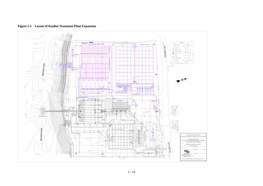
2 - 14
Up
Administration Building
Pumping Station
Up
Go to W
ATTAI
Exist. Flow Meter
Exist. Alum Tank Room
Exist. Filter
Season only)
Exist. Pumping Station
Exist. Chlorination Room
Exist. ElectricRoom
MEK
HO
NG
RIV
ERPolymer Feeding Facility
Intake PumpingStation
Exist. Flow Meter
( Used in Wet Drain Pump
ChamberExist. Mixing
Exist. Flocculation Basin
Exist. PolymerTank
Exist. Sedimentation Basin
Flowmeter
Air Blower & Air Compressor
& Mixing Basin
Exist. Clear Water Reservoir
Receiving Well
Chemical Sedimentation Basin
Flocculation Basin
Clear Water Reservoir
Go to KAO
LIEO
The Project for the Vientiane Water Supply Development in Lao People's Democratic Republic
GENERAL PLAN OF KAOLIEO WTP
JAPAN INTERNATIONAL COOPERATION AGENCY
CONSULTANTS CO., LTD.
EXPANSION PART
TOKYO, JAPAN
NIHON SUIDO
SCALE:
TITLE:
DESIGNED BY DATE
DRAWING NO.
APPROVED BY DATE
Ministry of Communication, Transport, Post and Construction
Lao People's Democratic Republic
The Basic Design Study on
FilterFlowmeter
Exist. Power Sub-Station
MEK
HO
NG
RIV
E R
Exist. Intake Tower
Figure 2-5 Layout of Kaolieo Treatment Plant Expansion

2 - 15
Figure 2-6 Treatment Process for Kaolieo Treatment Plant Expansion
Mixing WellGravitational ForceMixing by Weir
Flocculation BasinUp-down BaffledChannel Type
Sedimentation BasinConventional Type Uni-flow
Filtration BasinRapid Sand Filtration with Air
Scouring TypeFiltration Rate : 148.1 m/day
Chlorine
Coagulant
Distribution
Mekong RiverHWL=+172.20mLWL=+159.00mMaximum Turbidity:6,000 NTU
Polymer
Chlorine
Chlorine
Intake FacilitiesIntake Pipe TypeRaw Water Quantity:
、44,000 m3/d Submergible Pump
Receiving Well
ReservoirEffective Capacity =
11,000 m3Connected with Existing
Reservoir
Distribution PumpCapacity : 36.3 m3/min(Hourly Maximum 1.3)
Filter Back WashAir Scouring + Back
Wash
Design Capacity :40,000 m3/day

2 - 16
(3) Intake Facilities
1) Intake Structure
The following three options for the intake structure design were considered:
i) Intake tower (existing Kaolieo Intake)
ii) Intake gate (existing Chinaimo Intake)
iii) Intake pipe
The Intake Pipe was selected as the most appropriate design for this project because:
• selective intake based on the river water level will be possible;
• there will be no obstacles inside the river and on the river bank slope;
• accumulated sludge in the intake pipe and pump pit will be flushed using pressurized water from the intake
pump;
• access to the intake facilities for operation and maintenance will be easy; and
• construction costs are less than for the other types.
Intake Tower Type
(existing Kaolieo type) Intake Gate Type
(existing Chinaimo type) Intake Pipe Type
(proposed)
2) River Bank Protection
River bank protection works will be required at the upstream and downstream ends of the new intake facilities to
avoid bank erosion caused by river water flow. The river bank protection works will consist of slope protection,
anchor, and bed protection. River bank protection works are usually caused by erosion of the bottom part of the
protection structures, therefore adequate design and construction of the anchor and bed protection are very
important.
<River Bank Slope Protection>
The following three slope protection options were considered for use on this project:
• gabion mattresses;
172.00171.50
159.50
171.50
159.50

2 - 17
• concrete lining; and
• retaining walls.
The gabion mattress option was selected as the preferred option due to its ease of maintenance/repair, low costs,
and short construction period.
Gabion Mattress
Concrete Finishing
Retaining Wall
<Anchor>
A pipe pile anchor will be used because it can be installed under water. Other types of anchors would require
installation of coffer dams during anchor installation, which would be costly and difficult. The Pipe piles will be
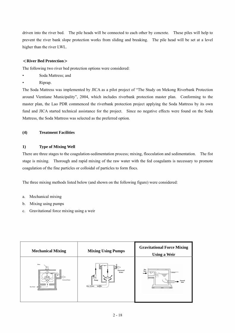
2 - 18
Raw Water
Processed Water
Motor
driven into the river bed. The pile heads will be connected to each other by concrete. These piles will help to
prevent the river bank slope protection works from sliding and breaking. The pile head will be set at a level
higher than the river LWL.
<River Bed Protection>
The following two river bed protection options were considered:
• Soda Mattress; and
• Riprap.
The Soda Mattress was implemented by JICA as a pilot project of “The Study on Mekong Riverbank Protection
around Vientiane Municipality”, 2004, which includes riverbank protection master plan. Conforming to the
master plan, the Lao PDR commenced the riverbank protection project applying the Soda Mattress by its own
fund and JICA started technical assistance for the project. Since no negative effects were found on the Soda
Mattress, the Soda Mattress was selected as the preferred option.
(4) Treatment Facilities
1) Type of Mixing Well
There are three stages to the coagulation-sedimentation process; mixing, flocculation and sedimentation. The fist
stage is mixing. Thorough and rapid mixing of the raw water with the fed coagulants is necessary to promote
coagulation of the fine particles or colloidal of particles to form flocs.
The three mixing methods listed below (and shown on the following figure) were considered:
a. Mechanical mixing
b. Mixing using pumps
c. Gravitational force mixing using a weir
Mechanical Mixing Mixing Using Pumps Gravitational Force Mixing
Using a Weir
RawWater
ProcessedWater
Pump
ProcessedWater
Raw Water

2 - 19
The gravitational mixing method is preferred for this project because of the minimum operation and maintenance
requirements. Also, the existing Kaolieo and Chinaimo Treatment Plants use the gravitational mixing method.
2) Type of Flocculation Basin
It is proposed that the flocculation basin will be a vertical baffled channel type basin, similar to those at the
existing Kaolieo and Chinaimo Water Treatment Plants. The mechanical agitation type of basin is not
recommended for this project because of its operation and maintenance requirements. The following figure
shows the vertical baffled channel type of basin and the mechanical agitation type of basin.
Mechanical Agitation (Flocculator) Baffled Channel
3) Type of Sedimentation Basin
The efficiency of the sedimentation basin (E) is determined using the following equation.
E=v0/(Q/A)
where A:horizontal area of the sedimentation basin
Q:flow rate into the sedimentation basin
v0:velocity of floc sedimentation
Q/A:overflow rate (surface loading)
The above equation indicates that the efficiency of the sedimentation basin can be improved by:
1. increasing the area of the sedimentation basin;
2. increasing the velocity of floc sedimentation; or
3. decreasing the flow rate into the sedimentation basin.
There are a range of different types of sedimentation basins that could be used for this project. The different
types of basins classified using the above three variables, are shown in the following table.
In le t P ro cessedW a ter
P a d d le (H o rizo n ta l)
In le t P ro cessedW a ter
P a d d le (V e r tica l)
Inlet
ProcessedWater
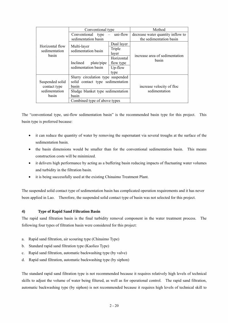
2 - 20
Conventional type Method Conventional type – uni-flow sedimentation basin
decrease water quantity inflow to the sedimentation basin
Dual layerMulti-layer sedimentation basin Triple
layer Horizontal flow type
Horizontal flow sedimentation
basin
Inclined plate/pipe sedimentation basin Up-flow
type
increase area of sedimentation basin
Slurry circulation type suspended solid contact type sedimentation basin Sludge blanket type sedimentation basin
Suspended solid contact type
sedimentation basin
Combined type of above types
increase velocity of floc sedimentation
The “conventional type, uni-flow sedimentation basin” is the recommended basin type for this project. This
basin type is preferred because:
• it can reduce the quantity of water by removing the supernatant via several troughs at the surface of the
sedimentation basin.
• the basin dimensions would be smaller than for the conventional sedimentation basin. This means
construction costs will be minimized.
• it delivers high performance by acting as a buffering basin reducing impacts of fluctuating water volumes
and turbidity in the filtration basin.
• it is being successfully used at the existing Chinaimo Treatment Plant.
The suspended solid contact type of sedimentation basin has complicated operation requirements and it has never
been applied in Lao. Therefore, the suspended solid contact type of basin was not selected for this project.
4) Type of Rapid Sand Filtration Basin
The rapid sand filtration basin is the final turbidity removal component in the water treatment process. The
following four types of filtration basin were considered for this project:
a. Rapid sand filtration, air scouring type (Chinaimo Type)
b. Standard rapid sand filtration type (Kaolieo Type)
c. Rapid sand filtration, automatic backwashing type (by valve)
d. Rapid sand filtration, automatic backwashing type (by siphon)
The standard rapid sand filtration type is not recommended because it requires relatively high levels of technical
skills to adjust the volume of water being filtered, as well as for operational control. The rapid sand filtration,
automatic backwashing type (by siphon) is not recommended because it requires high levels of technical skill to

2 - 21
operate, control and maintain because it has more devices than the other forms of rapid sand filtration.
The rapid sand filtration, automatic backwashing type (by valve) and air scouring type are easy to operate and
control, and require less frequent maintenance because there are fewer devices. Of these two, the rapid sand
filtration, air scouring type has the advantage of using less backwashing water. Also, the air scouring type is
used at the existing Chinaimo plant, therefore there is existing knowledge and understanding of how to operate
and maintain the system. Therefore, the rapid sand filtration, air scouring type (Chinaimo Type) is recommended
as the preferred option for this project.
Rapid sand filtration, air scouring type (Chinaimo
Type)
Standard rapid sand filtration type(Kaolieo
Type)
Rapid sand filtration, automatic
backwashing type (by valve)
Rapid sand filtration, automatic backwashing
type (by siphon)
(5) Other components of the treatment facilities
1) Intake and raw water transmission facilities
• Flushing piping using pressurized water from the intake pumps will be installed in the pump suction pit.
The piping will discharge accumulated sludge from the intake pipes and pump pit.
• The intake pump will be a submergible pump, similar to the one that is installed at the existing Chinaimo
Treatment Plant.
• The raw water flow meter will be ultrasonic.
• The raw water flow rate will be controlled by two sets of toothed vane butterfly valves.
2) Treatment Facilities
• A weir flow gauge will be installed between the receiving well and the mixing well. This will enable
measurement of the flow rate if the ultrasonic flow meter malfunctions.
• A steel gate will be installed at the baffle wall in the flocculation basin to discharge sludge from the
flocculation basin into the sedimentation basin.
• Pressurized raw water will be used to manually wash the flocculation and sedimentation basins.
InletInlet Valve
Volvocet(Controller)
Overflow/Oriffice
Influent Channel
Inlet
Sand
Gravel
Wash Waste
BackwashWater
SurfacewashWater
Trough
FilteredWater Wash
Waste
SurfacewashWater
Sand
Gravel
FilteredWater
Inlet
Trough
Filtration Process Washing Process
FilteredWaterfrom
AnotherBasins
2 - 22
• Sludge flushing pipes will be installed from the raw water intake pipe to assist desludging during cleaning of
the sedimentation basin.
3) Distribution Pumping Facilities
• A foot valve will be installed at the suction of the distribution pump rather than a complicated vacuum pump
system.
4) Electrical and Control Facilities
• New power transmission facilities will be installed for the new part of the plant. New facilities will not be
required for the existing part of the plant because the existing facilities are still sufficient.
• The GOL will install a dual source power supply, therefore an emergency generator will not be required.
• CRT and remote sensing will not be applied.
5) Yard piping and landscaping
• The desludging pipe from the sedimentation basin and the backwash drain from the filtration basin will be
connected to the existing man hall. The existing drainage system will be used.
• The discharged sludge and drain discharge will enter the Mekong River at the downstream end of the existing
intake tower via the existing man hall.
• Stormwater runoff will be discharged through a gutter system to the Mekong River using gravity flow.
(6) Components of the expansion of Kaolieo Treatment Plant
The basic design study has indicated that the components shown in Table 2-3 will be required for the expansion of
Kaolieo Treatment Plant.

2 - 23
Table 2-3 Components of Kaolieo Treatment Plant Expansion
Name of Facility / Equipment Component of Expansion Work
Intake Structure
Type : Intake Pipe Type RC Structure, 1Basin Intake Pumping Well : W8.00 m × L3.50 m × D15.50 m Pump House : W8.00m × L6.00 m (48.0 m2 ), Pump House Floor : Grating
River Bank & River Bed Protection
Slope Protection : Gabion Mattress Work Anchor of Slope Protection : Pipe Pile Anchor Work (head of piles will be connected each other by RC) Bed Protection : Soda Mattress Work Submersible Pump : 15.3 m3/min × 19.5 m × 75 kW × 3 Units(1-Standby) Intake Pump Check Valve : D350mm × 3 Units Discharge Valve : D350 mm Electric Motor-drive Type Short Body Type Butterfly Valve (Horizontal Type) × 3 Units
Inlet Pipes & Stop Valves
Inlet Pipe : D1,000 mm × 3 Pieces Inlet Screen : Fixed Bar Screen x 3 Sets Stop Valve : D1,000 mm Short Body Type Butterfly Valve (Vertical Type) with Manual Operating Stand x 3 Units
Flashing Piping Devices for Prevention of Pile-up Soil
Gate Valve : D300 mm Sluice Valve with Manual Operating Stand × 7 Units Flashing Pipe : D300 mm × 2 Pieces Flashing pipe with Slit : D300 mm × D150 mm × 1 Piece Stop Log for Bottom Pipe : D1,000 mm with Manual Operating Stand
Intake Facilities
Crane Equipment
5 ton Electric Motor-drive Chain Hoist Crane (Traversing, Traveling, Hoisting) × 1 Unit
Raw Water Transmission Main
DIP : D700 mm × L15 m DIP : D500 mm × L15 m
Raw Water Flow Meter Chamber & Flow Control Valve Chamber
Raw Water Transmission Facilities
Flow Meter & Flow Control Valve Facility
Flow Control Valve : D500 mm Tooth-shaped Disk Type Butterfly Valve (Horizontal Type) × 2 Units (Electric Motor-drive Type × 1 Unit、 Manual Type × 1 Unit)
Receiving Well RC Structure、1Basin、Detention Time = 2.3 min. Dimension : W2.80 m × L5.60 m × D5.10 m × E.D4.50 m
Receiving Well & Mixing Well Facilities Mixing Well Mixing Type : Gravitational Force Mixing by Weir Type
RC Structure, 1 Basin、Detention Time = 1.0 min. Dimension : W2.80 m × L2.80 m × D5.10 m × E.D3.84 m
Flocculation Basin
Flocculation Type : Baffled Channel Type RC Structure, 4 Basin、Detention Time = 23.7 min. (Except Outlet Zone) Dimension : W8.55 m × L10.15 m × Av.D3.70 m × Av.E.D3.05 m
Sedimentation Basin
Sedimentation Type : Conventional Type – Uni-flow Type (Horizontal Flow) RC Structure, 4 Basin、Detention Time = 2.1 hr (Substantially = 3.5hr) Dimension : W8.55 m × L33.00 m × Av.D4.05 m × Av.E.D3.43 m Flocculation Basin : Steel Plate Slide Gate for Sludge Drain – 23 Sets / Basin Sedimentation Basin : D300 mm Sludge Drain Valve with Manual Operating Stand × 8 Units Enhanced Sludge Drain System for Sedimented Sludge : Pressurized Piping with Slit D250 mm × 4 Lots (Utilizing Pressurized Raw Water)
Flocculation & Sedimentation Facilities
Sludge Drain Facilities (Flocculation &Sedimentation Basin) Pressurized Cleaning Piping System for Flocculation and Sedimentation Basins : Utilizing
Raw Water Pumping Well : RC Structure, 1 Basin、Detention Time = 10 min.(V=7.5m3) Submersible Pump : 0.75 m3/min × 60 m × 15 kW × 1 Unit Filtration Type : Rapid Sand Filtration - Air Scouring Type RC Structure, 6 Basin、 Filtered Area = 49.6 m2/Basin ( Dimension : W4.55 m × L10.5 m) Filtration Rate : 147.8 m/d Back Wash Rate = 0.36 m3/min/m2
Air Scouring Rate = 1.00 m3/min/m2 Sand : Effective Size = 1.0 mm Depth of Sand = 1.0 m
Rapid Sand Filtration Basin
Under drain System : Porous Plate Type Inlet Valve : D700 mm Electric Motor-drive Type Wafer–type Butterfly Valve with Locking Device × 6 Units (1 Unit/Basin)
Filtration Facilities
Operating Valves for Filtration Back Wash Valve : D500 mm Electric Motor-drive Type Wafer–type Butterfly Valve × 6 Units
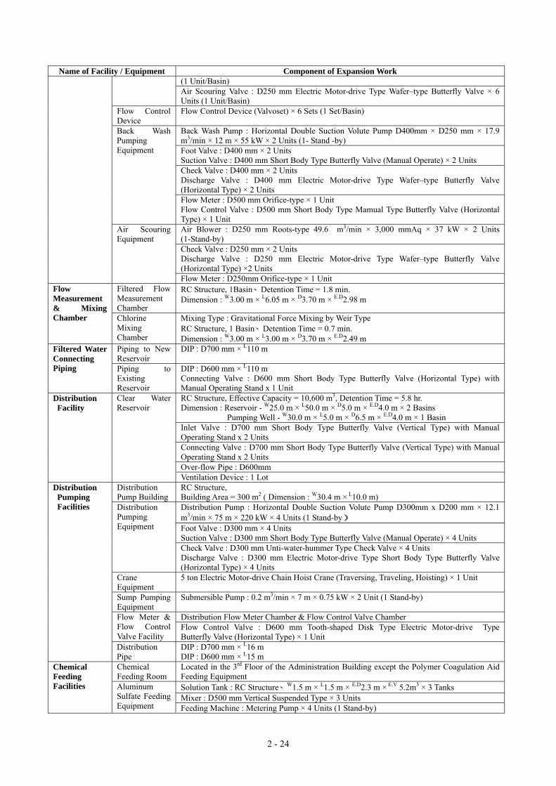
2 - 24
Name of Facility / Equipment Component of Expansion Work (1 Unit/Basin) Air Scouring Valve : D250 mm Electric Motor-drive Type Wafer–type Butterfly Valve × 6 Units (1 Unit/Basin)
Flow Control Device
Flow Control Device (Valvoset) × 6 Sets (1 Set/Basin)
Back Wash Pump : Horizontal Double Suction Volute Pump D400mm × D250 mm × 17.9 m3/min × 12 m × 55 kW × 2 Units (1- Stand -by) Foot Valve : D400 mm × 2 Units Suction Valve : D400 mm Short Body Type Butterfly Valve (Manual Operate) × 2 Units Check Valve : D400 mm × 2 Units Discharge Valve : D400 mm Electric Motor-drive Type Wafer–type Butterfly Valve (Horizontal Type) × 2 Units
Back Wash Pumping Equipment
Flow Meter : D500 mm Orifice-type × 1 Unit Flow Control Valve : D500 mm Short Body Type Mamual Type Butterfly Valve (Horizontal Type) × 1 Unit Air Blower : D250 mm Roots-type 49.6 m3/min × 3,000 mmAq × 37 kW × 2 Units (1-Stand-by) Check Valve : D250 mm × 2 Units Discharge Valve : D250 mm Electric Motor-drive Type Wafer–type Butterfly Valve (Horizontal Type) ×2 Units
Air Scouring Equipment
Flow Meter : D250mm Orifice-type × 1 Unit Filtered Flow Measurement Chamber
RC Structure, 1Basin、Detention Time = 1.8 min. Dimension : W3.00 m × L6.05 m × D3.70 m × E.D2.98 m
Flow Measurement & Mixing Chamber Chlorine
Mixing Chamber
Mixing Type : Gravitational Force Mixing by Weir Type RC Structure, 1 Basin、Detention Time = 0.7 min. Dimension : W3.00 m × L3.00 m × D3.70 m × E.D2.49 m
Piping to New Reservoir
DIP : D700 mm × L110 m Filtered Water Connecting Piping Piping to
Existing Reservoir
DIP : D600 mm × L110 m Connecting Valve : D600 mm Short Body Type Butterfly Valve (Horizontal Type) with Manual Operating Stand x 1 Unit RC Structure, Effective Capacity = 10,600 m3, Detention Time = 5.8 hr. Dimension : Reservoir - W25.0 m × L50.0 m × D5.0 m × E.D4.0 m × 2 Basins
Pumping Well - W30.0 m × L5.0 m × D6.5 m × E.D4.0 m × 1 Basin Inlet Valve : D700 mm Short Body Type Butterfly Valve (Vertical Type) with Manual Operating Stand x 2 Units Connecting Valve : D700 mm Short Body Type Butterfly Valve (Vertical Type) with Manual Operating Stand x 2 Units Over-flow Pipe : D600mm
Distribution Facility
Clear Water Reservoir
Ventilation Device : 1 Lot Distribution Pump Building
RC Structure, Building Area = 300 m2 ( Dimension : W30.4 m × L10.0 m) Distribution Pump : Horizontal Double Suction Volute Pump D300mm x D200 mm × 12.1 m3/min × 75 m × 220 kW × 4 Units (1 Stand-by) Foot Valve : D300 mm × 4 Units Suction Valve : D300 mm Short Body Type Butterfly Valve (Manual Operate) × 4 Units
Distribution Pumping Equipment
Check Valve : D300 mm Unti-water-hummer Type Check Valve × 4 Units Discharge Valve : D300 mm Electric Motor-drive Type Short Body Type Butterfly Valve (Horizontal Type) × 4 Units
Crane Equipment
5 ton Electric Motor-drive Chain Hoist Crane (Traversing, Traveling, Hoisting) × 1 Unit
Sump Pumping Equipment
Submersible Pump : 0.2 m3/min × 7 m × 0.75 kW × 2 Unit (1 Stand-by)
Distribution Flow Meter Chamber & Flow Control Valve Chamber Flow Meter & Flow Control Valve Facility
Flow Control Valve : D600 mm Tooth-shaped Disk Type Electric Motor-drive Type Butterfly Valve (Horizontal Type) × 1 Unit
Distribution Pumping Facilities
Distribution Pipe
DIP : D700 mm × L16 m DIP : D600 mm × L15 m
Chemical Feeding Room
Located in the 3rd Floor of the Administration Building except the Polymer Coagulation Aid Feeding Equipment Solution Tank : RC Structure、W1.5 m × L1.5 m × E.D2.3 m × E.V 5.2m3 × 3 Tanks Mixer : D500 mm Vertical Suspended Type × 3 Units
Chemical Feeding Facilities Aluminum
Sulfate Feeding Equipment Feeding Machine : Metering Pump × 4 Units (1 Stand-by)

2 - 25
Name of Facility / Equipment Component of Expansion Work Crane Equipment
1 ton Electric Motor-drive Chain Hoist Crane (Traveling, Hoisting) × 1 Unit
Feeding Room : Located in the vicinity of the Mixing Well Solution Tank : Polyethylene Resin、D1.0 m × E.D1.3 m × E.V 1.0m3× 3 Tanks Mixer : D350 mm Vertical Suspended Type × 3 Units
Polymer Coagulation Aid Feeding Equipment Feeding Machine : Metering Pump × 2 Units (1 Stand-by)
Solution Tank : RC Structure、W1.5 m × L1.5 m × E.D2.2 m × E.V 5.0m3 × 3 Tanks Mixer : D500 mm Vertical Suspended Type × 3 Units
Calcium Hypochlorite Feeding Equipment
Feeding Machine : Metering Pump × 4 Units (Pre-Chlorination : 2 Units (1 Stand-by), Post-Chlorination : 2 Units (1 Stand-by))
Power Receiving & Transformer Equipment
Capacity of Expansion : 1,400 kVA
Power Receiving Panel, Power Supply Panel & Auxiliary Power Supply Panel for Intake Pump (Located in Intake Pump House) Power Supply Panel for Filter’s Operation Equipment (Locate in Distribution Pump Building)Power Receiving Panel, Power Supply Panel, Auxiliary Power Supply Panel & Local Panel for Distribution Pump
Power Supply Equipment
Power Supply Panel for Chemical Feeding Facilities including the Existing (Located in Distribution Pump Building) Control Panel for Raw Water Flow Rate & Distribution Flow Rate Control Panel for Submersible Pump of Sedimentation Cleaning Control Panel for Filter’s Operation (Located in Filter’s Operation Gallery)
Control Panel
Control Panel for Chemical Feeding Facilities including the Existing (Located in Chemical Feeding Room)
Air Conditioning Facilities
Installation of Air Conditioning Facilities (Located in Electrical Room of Distribution Pump Building and Administration Building)
Lightning Protection Equipment
Lightning Rod Equipment (Located in Raw Water Intake House, Filtration Gallery, Administration Building、Distribution Building)
Electrical Facilities
Inter- communication System inside the Treatment Plant
Intercommunication Equipment (Located in Raw Water Intake House, Polymer Feeding Room、Filter’s Operation Gallery, Distribution Pump Building, Administration Building)
Central Supervising Panel & Instrumentation Panel including Existing (Located in Operation Room of Administration Building)
Raw Water Level Meter : Ultrasonic Type - Water Level for Raw Water Intake Pumping Well (Mekong River) Raw Water Flow Meter : Ultrasonic Type (Non-Retractable Type) Total Filtered Flow Meter : Suppressed Rectangular Weir – Float Type Filtration Resistance Meter : Electronic Type Clear Water Reservoir Level Meter : Ultrasonic Type Distribution Line Pressure Meter : Electronic Type Distribution Flow Meter : Ultrasonic Type (Non-Retractable Type)
Instrumentation Facilities
Instrumentation Equipment
Chemical Solution Tank Level Meter : Electrode Type Administration Building RC Structure、Floor Area = 213 m2 × 3 F (Dimension : W19.80 m × L10.78 m × 3 F),
Management office, Laboratory, Control Room & Chemical Feeding Facilities Located in Administration Building Laboratory Water Quality Analysis Equipment & Reagent
Landscaping and Others Site Preparation, Embankment (Ground Leveling +172.20 m), Roads, Lighting, Gate & Fence, others

2 - 26
2-2-2-4 Rehabilitation of Kaolieo Treatment Plant
The Kaolieo Treatment Plant was constructed in 1964 with a capacity of 20,000 m3/day. The Kaolieo Treatment
Plant is the oldest treatment plant in Vientiane. During 1983, 20 years after construction, the treatment plant was
rehabilitated. It is now over 20 years since the plant was rehabilitated and the facilities and the electrical and
mechanical equipment are now in poor condition and often malfunction. In particular, the treatment capacity of
the plant has decreased because the pumps are old and inefficient.
Although there are many problems with the plant, the NPVC has not been able to undertake any further upgrades.
Therefore the NPVC operates all of the stand-by pumps continuously to meet the increasing water demand. This
means there is no stand-by equipment and therefore if there is a malfunction, the whole plant must shut down.
It is therefore clear that rehabilitation of the existing Kaolieo Treatment Plant is a priority if sustainable water
supply to the city is to be secured.
(1) Outlines of the Rehabilitation Work
1) Basic concepts of the rehabilitation work
The basic concepts of the rehabilitation work proposed for the Kaolieo Treatment Plant are summarized here:
• Operation of the existing plant will be suspended for several months to allow for the implementation of the
rehabilitation work.
• To avoid a reduction in the amount of treated water being supplied, the rehabilitation work should be
implemented after the treatment process has been expanded.
• A gravity system will be introduced instead of using a mechanical system because gravity systems are easier
to operate and maintain and they are more energy efficient.
• Operation and maintenance costs will be minimized.
• Existing facilities and equipment will be used wherever possible.
• To simplify operation, equipment or valves that are frequently used will be converted to electrical controls,
however automatic operation will not be introduced.
• To reduce operating points, facilities will be shared with the expanded treatment process.
• The ground surface level will be landscaped to a level of +172.2. This is the high water level of the
Mekong River. A small embankment along the river will be constructed to a level of +173.0 m to provide
flood protection.
The proposed layout of the rehabilitation work is shown on Figure 2-7.

2 - 27
2) Water Treatment Process
The existing water treatment system at the Kaolieo Treatment Plant consists of an intake facility, treatment
facilities, a distribution pumping station, chemical feeding facilities, an electrical and control system, and an
administration building. The direction of flow between these treatment processes is shown on Figure 2-8.

2 - 28
Up
RoomOperator
Exist. Filter
Filter
Exist. Flocculation Basin
MEK
HO
NG
RIV
ER
Season only)
Exist. Receiving
Drain Pump( Used in Wet
Well
Up
Chemical Sedimentation Basin
Flowmeter
Go to W
ATTAI
Exist. Pumping Station
Exist. Clear Water Reservoir
Polymer FeedingFacility
Exist. Sedimentation Basin
Air Blower & Air Compressor
Intake PumpingStation
Exist. Flow Meter
Polymer Feeding Facility
Flowmeter
Receiving Well
Administration Building
Pumping Station
Go to KAO
LIEO
Exist. Power Sub-Station
Flowmeter
MEK
HO
NG
RIV
ER
Exist. Intake Tower
& Mixing Basin
Flocculation Basin
Exist. ElectricRoom
Clear Water Reservoir
Lao People's Democratic Republic
Ministry of Communication, Transport, Post and Construction
The Basic Design Study on
DATE
DRAWING NO.
APPROVED BY
DATEDESIGNED BY
TITLE:
SCALE:
TOKYO, JAPAN
NIHON SUIDO
Lao People's Democratic Republic
GENERAL PLAN OF KAOLIEO WTP
JAPAN INTERNATIONAL COOPERATION AGENCY
CONSULTANTS CO., LTD.
REHABILITATION PART
The Project for the Vientiane Water Supply Development in
Figure 2-7 Layout of Rehabilitation Work of Kaolieo Treatment Plant
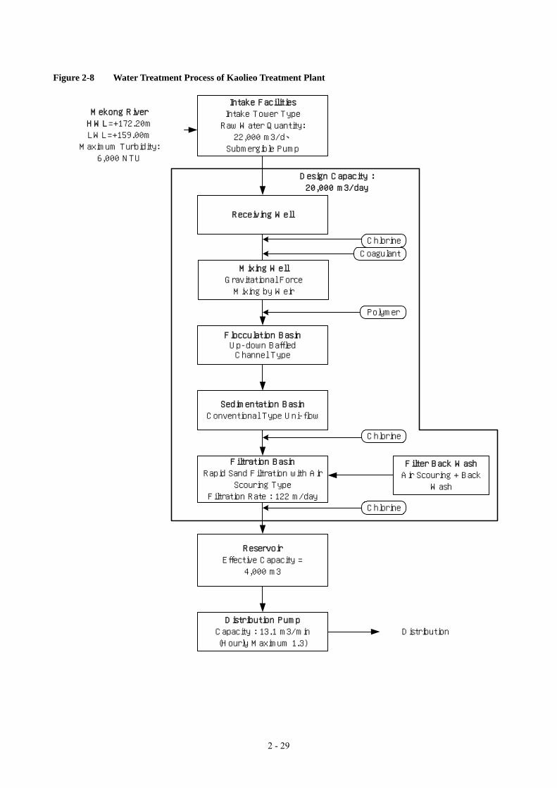
2 - 29
Figure 2-8 Water Treatment Process of Kaolieo Treatment Plant
Flocculation BasinUp-down BaffledChannel Type
Sedimentation BasinConventional Type Uni-flow
Filtration BasinRapid Sand Filtration with Air
Scouring TypeFiltration Rate : 122 m/day
Chlorine
Coagulant
Distribution
Mekong RiverHWL=+172.20mLWL=+159.00mMaximum Turbidity:6,000 NTU
Polymer
Intake FacilitiesIntake Tower TypeRaw Water Quantity:
、22,000 m3/d Submergible Pump
Receiving Well
ReservoirEffective Capacity =
4,000 m3
Distribution PumpCapacity : 13.1 m3/min(Hourly Maximum 1.3)
Filter Back WashAir Scouring + Back
Wash
Design Capacity :20,000 m3/day
Chlorine
Chlorine
Mixing WellGravitational ForceMixing by Weir

2 - 30
(2) Components of the Rehabilitation Work
1) Intake Facilities and Raw Water Transmission System
• The existing intake pumps will be replaced by submergible pumps which are similar to those used at the
Chinaimo Treatment Plant.
• The raw water inflow rate will be controlled using toothed vane butterfly valves (two sets).
2) Treatment Process
• The existing opening at the receiving well will be closed converted to a weir. Gravitational force mixing at
this weir will be used to mix the chemicals, meaning the mechanical flush mixer can be removed.
• The existing wooden separation wall within the flocculation basin will be converted to a concrete weir.
Polymer dosing will occur at the weir.
• The existing openings at the effluent of the flocculation basin will be closed and converted to a weir because
these openings currently cause spout flow and destroy flocs.
• A steel gate will be installed at the baffle wall in the flocculation basin to discharge sludge from the
flocculation basin into the sedimentation basin.
• Pressurized raw water will be used for manual washing of the flocculation and sedimentation basins.
• Sludge flushing pipes will be installed from the raw water intake pipe to assist desludging during cleaning of
the sedimentation basin.
• Gravel filters will be removed and replaced with a flow regulation wall and trough to remove the supernatant.
The gravel filters will be removed because their efficiency cannot be confirmed and they require time
consuming manual cleaning.
• The filter backwash method will be changed from “surface wash + backwash” to “air scouring + backwash”.
The required air blowers and backwash pumps will be shared with the expanded treatment process.
• The under drain of the filtration basin will be replaced by a polus concrete plate.
• The existing surface washing piping and backwash water drain trough at the filtration basin will be removed.
A channel for filtered water, air, and drainage will be installed in the center of the filtration basin.
3) Distribution Pumping Facilities
• A foot valve will be installed at the suction of the distribution pump instead of a complicated vacuum pump
system.
4) Chemical Feeding Facilities
• The chemical feeding facilities (except for polymer feeding) will be combined with the expanded facilities.
5) Electrical and Control Facilities
• The existing power transmission facilities will be used with minor repair work.
• The GOL will install a dual source power supply therefore an emergency generator will not be required.
2 - 31
• CRT and remote sensing will not be applied.
(3) Components of the Rehabilitation Work of Kaolieo Treatment Plant
The basic design study has identified that the components shown in Table 2-4 are required for the rehabilitation of
Kaolieo Treatment Plant.

2 - 32
Table 2-4 Components of Rehabilitation Work of Kaolieo Treatment Plant Name of Facility / Equipment Component of Existing Component of Rehabilitation Work
Intake Structure • Intake Tower Type Renovate • Replacement of Doors & Windows • Rust Removal & Painting of Handrails • Substitute Grating for Checked Plate of Pump House Floor
River Bank & River Bed Protection
• Upstream of Tower : Gabion Mattress Work & Riprap Work
• Downstream of Tower : Gabion Mattress Work with Pipe Pile Anchor Work
Improve • Reinforcement of Existing River Bed Protection by Soda Mattress Work
• River Bank & River Bed Protection Area/Place to be constructed by Expanded Intake Structure included in Expansion Work
• Vertical Mixed Flow Pump : D250 mm × 7.65 m3/min × 19.5 m × 37 kW × 3 Units (1-Standby) - Located in Intake Tower
• Horizontal Single Suction Volute Pump : D200 mm × 4.5 m3/min × 40 m × 45 kW × 1 Unit – Located on Floating Dock
Replace • Submersible Pump : D250 mm × 7.7 m3/min × 20.5 m × 45 kW × 3 Units (1-Standby)
• Removal of Horizontal Single Suction Volute Pump including Valves & Piping with Floating Dock
Intake Pump
• D250 mm Check Valve • D250 mm Gate Valve
Replace • D250 mm Check Valve • D250 mm Short Body Type Electric Motor-drive Butterfly Valve
(Horizontal Type) Crane Equipment • 5 ton Electric Motor-drive Chain Block × 3 Units Replace • 5 ton Electric Motor-drive Chain Hoist Crane (Traversing, Traveling,
Hoisting) × 1 Unit
Intake Facilities
Maintenance Bridge
• Steel Truss Bridge with Wooden Plates Renovate • Rust Removal & Painting • Replace Wooden Plates with Lightweight Grating
Raw Water Transmission Main
• Steel Pipe : D500 mm Repair • Rust Removal & Painting of Steel Pipe Raw Water Transmission Facilities
Flow Control Valve
• D500 mm × Manual Operate Type Butterfly Valve (Horizontal Type) × 1 Unit
Replace • D500 mm × Tooth-shaped Disc Type Butterfly Valve (Horizontal Type) × 2 Units (Electric Motor-drive Type × 1 Unit、Manual Type × 1 Unit)
Receiving Well (Mixing Well)
• RC Structure, 1 Basin, Detention Time = 1.6 min Improve • Plug a Opening of Outlet Wall and Rebuild the Weir for Coagulation Receiving Well & Mixing Well Facilities Flash Mixer • Vertical Suspended Type Mixer × 1 Unit Locate in
Receiving Well Remove • Remove due to modification of the existing coagulation method
(Gravitational Force Mixing by Weir Type) • RC Structure, 4 Basins • Flocculation Type : Baffled Channel Type • Detention Time = 37.8 min (Except Outlet Zone)
Improve • Rebuild the Weir from the Existing Wooden Wall for Coagulation Aid
• Improvement of the Existing Baffled Channel Walls • Plug 4-Opening of Outlet Wall and Rebuild the Weir for Prevention
of Jet Flow
Flocculation Basin
• Inlet Valve : D400 mm × 2 Units Replace • D400 mm Manual Operate Sluice Valve × 2 Units
Flocculation & Sedimentation Facilities
Sedimentation Basin
• RC Structure、4 Basins • Sedimentation Type : Conventional Type with Gravel
Filter • Detention Time = 2.0 hr (3.2 hr including Gravel Filter)
Improve • Installation of Intermediate Perforated Baffle Wall • Remove Gravel Filter • Substitute Outlet Launders (Uni-flow Type) for Gravel Filter • Replace Ladder • Rust Removal & Painting of Handrail

2 - 33
Name of Facility / Equipment Component of Existing Component of Rehabilitation Work • Drain Valve : D150 mm × 2 Units (Located Outlet
Channel) Replace • D150 mm Manual Operate Sluice Valve × 2 Units
• Occurrence of Leakage from Structural Wall Repair • Repair of Structural Wall’s Clacks • Flocculation Basin : Drain Valve D250 mm × 4 Units Not in Use
(Untreated) • Installation of Steel Plate Slide Gate for Desludging – 11 Sets/Basin • Substitute Steel Plate Slide Gate for Drain Valve
• Sedimentation Basin : Sludge Valve D300 mm × 4 Units Replace • D300 mm Sluice Valve with Manual Operating Stand × 4 Units
Desludging Equipment (Flocculation & Sedimentation Basin)
• Pressurized Water Supply System for Cleaning of Flocculation & Sedimentation Basin
Improve • Enhanced Desludging System for Sedimented Sludge : Pressurized Piping with Slit D250 mm × 4 Lots (Commonage Expanded Pressurized Raw Water System)
• Pressurized Cleaning Piping System for Flocculation & Sedimentation Basin : Commonage Expanded Raw Water Pumping System)
• RC Structure、4 Basins • Filtration Type : Rapid Sand Filtration – Surface wash
& Backwash Water System • Under drain System : Strainer Type • Filtered Area = 45.1 m2/Basin (Dimension : W5.5 m ×
L8.2 m) • Filtration Rate = 122 m/d • Backwash Rate = 0.60 m3/min/m2
• Surface wash Rate = 0.15 m3/min/m2 • Wash Water Troughs
Improve • Filtration Type : Substitute Rapid Sand Filtration – Air Scouring Type same as Expansion for Existing – Surface wash & Backwash Water System
• Under drain System : Porous Plate Type • Filtered Area = 36.9 m2/Basin (Dimension : W4.5 m × L8.2 m) • Filtration Rate = 149.1 m/d • Backwash Rate = 0.36 m3/min/m2 • Air Scouring Rate = 1.00 m3/min/m2 • Remove Wash Water Troughs • Rebuild Filtered Water Chamber, Air Scouring Chamber & Wash
Water Drain Chamber in Central Part of Filter Basin
Rapid Sand Filtration basin
• Effective Size of Sand = 0.8 mm • Depth of Sand =1.0 m
Reuse • Reuse of Existing Sand after Cleaning
• Inlet Valve : D300 mm Sluice Valve with Manual Operating Stand × 4 Units (1 Unit/Basin)
Replace • D300 mm Wafer-Type Electric Motor-drive Butterfly Valve (Horizontal Type) × 4 Units (1 Unit/Basin)
• Filtered Valve : D250 mm Sluice Valve with Manual Operating Stand × 4 Units (1 Unit/Basin)
Replace • D250 mm Wafer-Type Butterfly Valve (Vertical Type) with Electric Motor-drive × 4 Units (1 Unit/Basin)
• Wash Water Drain Valve : D450 mm Top Valve with Manual Operating Stand × 8 Units (2 Units/Basin)
Replace • D450 mm Wafer-Type Electric Motor-drive Butterfly Valve (Horizontal Type) × 4 Units (1 Unit/Basin)
• 1-D450 mm Top Valve not in Use • Back Wash Valve : D450 mm Sluice Valve with Manual
Operating Stand × 4 Units (1 Unit/Basin) Replace • D450 mm Wafer-Type Electric Motor-drive Butterfly Valve (Vertical
Type) × 4 Units (1 Unit/Basin) ― New • Inlet Gate : 300mm × 300mm × Electric Motor-drive Gate × 8 Units
(2 Unit/Basin) • Surface Wash Valve : D200 mm Sluice Valve with
Manual Operating Stand × 4 Units (1 Unit/Basin) • Surface Wash Piping System in Filtration Basin
Remove ―
― New • Air Scouring Valve : D250 mm Wafer-Type Electric Motor-drive Butterfly Valve (Horizontal Type) × 4 Units (1 Unit/Basin)
Filtration Facilities
Operating Valves & piping
• Filtered Flow Meter : Venturi Meter Replace • Replacement of Filtered Flow Meter : Paddle Type with Transmitter

2 - 34
Name of Facility / Equipment Component of Existing Component of Rehabilitation Work • Outlet Valve (D250 mm Sluice Valve) is used as both
Filtered Valve and Control Valve • Outlet Valve (D250 mm Wafer-Type Butterfly Valve) is used as both
Filtered Valve and Control Valve Surface Wash Pumping Equipment
• No Equipment for Sole Use • Backwash Pumps are used Surface Washing in
combination with Back Washing
Remove ―
Back Wash Pumping Equipment
• Backwash Pump : Horizontal Double Suction Volute Pump D350 mm × D250 mm × 14.5 m3/min × 18 m × 60 kW × 3 Units (1-Standby)
Remove • Back Wash Pumping Equipment is used in common.
• Flow Control Valve : D450 mm Manual Operate Butterfly Valve (Horizontal Type) × 1 Unit
Replace • D450 mm Short Body Type Manual Type Butterfly Valve (Horizontal Type)
Backwash Flow Control Valve & Flow Meter ― New • D450 mm Orifice Type × 1 Unit Surface Wash Flow Control Valve
• Flow Control Valve : D200 mm Butterfly Valve (Horizontal Type) × 1 Unit
Remove ―
Air Scouring Flow Meter
― ― • Expanded D250mm Air Scouring Flow Meter (Orifice Type) is used in common.
Air Scouring Flow Control Valve
― ― • Expanded Air Scouring Equipment is used in common.
Filtration Facilities
Drain Valve • Drain Valve : D100 mm Sluice Valve × 4 Units Replace • Drain Valve : D100 mm Wafer-Type Electric Motor-drive Butterfly Valve (Horizontal Type) × 4 Units (1 Unit/Basin)
Clear Water Reservoir
• RC Structure、2 Basins • Effective Capacity = 3,940 m3 • Detention Time = 4.7 hr
Repair • Extended Walls of Opening Structures
• Inlet Valve : D400 mm Sluice Valve with Manual Operating Stand × 2 Units
Replace • Inlet Valve : D400 mm Sluice Valve with Manual Operating Stand × 2 Units
• Maintenance Valve : D300 mm Sluice Valve with Manual Operating Stand × 6 Units
Repair • Replacement of Intermediate Shaft and Manual Operating Stand for Inlet Valve
• Maintenance Valve : D350 mm Sluice Valve with Manual Operating Stand × 2 Units
Repair • Replacement of Intermediate Shaft and Manual Operating Stand for Inlet Valve
Distribution Facilities
Maintenance Valve Equipment
• Stop Valve for Overflow Pipe : D200 mm Sluice Valve with Manual Operating Stand × 2 Units
Repair • Replacement of Intermediate Shaft and Manual Operating Stand for Inlet Valve
Distribution Pump Building
• RC Structure、Building Area = 160 m2 Repair • Extended Perimeter’s Walls of Entrance • Construction of Stairs for Entrance
Distribution Pumping Facilities Distribution
Pumping Equipment
• Distribution Pump : Horizontal Double Suction Volute Pump D250 mm × 150 mm × 6.3 m3/min × 67 m × 110 kW × 4 Units (1-Standby)
Replace • Distribution Pump : Horizontal Double Suction Volute Pump D250 mm × 150 mm × 5.9 m3/min × 75 m × 120 kW × 4 Units (1-Standby)
• Pump-priming System : Vacuum Pump System New • Pump-priming System : Foot Valve System • Foot Valve : D250 mm × 4 Units
Distribution Pumping Facilities
Distribution Pumping Equipment • Check Valve : D200 mm
• Discharge Valve : D200 mm Sluice Valve Replace • Check Valve : D200 mm Unti-water-hummer Type Check Valve × 4
Units • Discharge Valve : D200 mm Electric Motor-drive Short Body Type
Butterfly Valve (Horizontal Type) × 4 Units

2 - 35
Name of Facility / Equipment Component of Existing Component of Rehabilitation Work Sump Pumping Equipment
― New • Submersible Pump : 0.2 m3/min × 7 m × 0.75 kW × 2 Units (1 Stand-by)
Crane Equipment • 5 ton Manual Operate Chain Hoist Replace 3 ton Electric Motor-drive Chain Hoist Crane (Traversing, Traveling, Hoisting) × 1 Unit
• 2-Flow Meter Chambers (Upstream Side-Flow Meter Chamber : Out of Use)
Reuse • Extended Walls of Existing 2-Chambers • Using Upstream Chamber for Flow Meter Chamber • Using Downstream Chamber for Flow Control Valve Chamber
Distribution Flow Control Valve & Flow Meter Facilities ― New • Flow Control Valve : D400 mm Tooth-shaped Disk Type Electric
Motor-drive Butterfly Valve Horizontal Type) × 1 unit Distribution Main • CIP : D450 mm Reuse ― By-Pass Pipe ― New By-Pass Pipe : DIP D450 mm × L 50 m Chemical Feeding Room
• For Aluminum Sulfate : West Side of Filer Basin • For Calcium Hypochlorite : Inlet Side of Clear Water
Reservoir
Relocate • Relocation of the Expanded New Administration Building • Remove of the All Existing Feeding Equipment
• Solution Tank : FRP Circular Cylinder Type 5.5 m3 × 3 Units
• Daily Use Tank : SUS 0.1m3 × 1 Unit • Transfer Pump : Removed
Replace • Solution Tank : RC Structure Located in Expanded New Administration Building
• Dimension : W1.1 m × L1.1 m × E.D2.2 m × E.V 2.6m3 × 2 Tanks
• Mixer : Vertical Suspended Type × 3 Units Replace • Mixer : Vertical Suspended Type D400mm × 2 Units (Located in Expanded New Administration Building)
Chemical Feeding Facilities
Aluminum Sulfate Feeding Equipment
• Feeding Machine : Orifice Flow Meter Type × 2 Unit Replace • Feeding Machine : Metering Pump × 3 Units (1 Stand-by) (Located in Expanded New Administration Building)
• Feeding Room : Located on the Receiving Well Replace • Relocate in West Side of the Receiving Well • Remove the Existing Feeding Room
• Solution Tank : Polyethylene Resin、D1.0 m × E.D1.3 m × 3 Tanks
Replace • Solution Tank : Polyethylene Resin、D1.0 m × E.D 1.3 m × E.V 1.0m3 × 2 Tanks
― New • Mixer : Vertical Suspended Type D350 mm × 2 Units
Polymer Coagulation Aid Feeding Equipment
― New • Feeding Machine : Metering Pump× 2 Units (1 Stand-by) • Solution Tank : FRP Circular Cylinder Type 0.8 m3 × 2
Units • Daily Use Tank : SUS 0.05m3 × 1 Unit • Transfer Pump : Removed
Replace • Solution Tank : RC Structure Located in Expanded New Administration Building
• Dimension : W1.35 m × L1.35 m × E.D2.2 m × E.V 4.0m3 × 2 Tanks
― New • Mixer : Vertical Suspended Type D400mm × 2 Units (Located in Expanded New Administration Building)
Chemical Feeding Facilities
Calcium Hypochlorite Feeding Equipment
― New • Feeding Machine ×Metering Pump × 4 Units (Pre-Chlorination : 2 Units (1 Stand-by), Post-Chlorination : 2 Units (1 Stand-by))
Power Receiving & Transformer Equipment
Existing Capacity : 750 kVA Reuse • Reuse of Existing Power Receiving & Transformer • Replacement of Consumable Goods (Oil, etc.) & Deteriorated
Accessories • Power Receiving Panel (Located in Electrical Room) Replace • Replace of Power Receiving Panel
Electrical Facilities
Power Supply Equipment • Distribution Board for Power & Lighting (Located in
Electrical Room) Replace • Replace of Distribution Board for Power & Lighting

2 - 36
Name of Facility / Equipment Component of Existing Component of Rehabilitation Work • Power Supply Panel & Auxiliary Power Supply Panel
for Intake Pump (Located in Intake Pump Room) Replace Replace of Power Supply Panel & Auxiliary Power Supply Panel for
Intake Pump • Power Supply Panel for Backwash Pump (Located in
Distribution Pump Building) Remove • Remove of Power Supply Panel for Backwash Pump
― New • Power Supply Panel for Filtration’s Equipment (Located in Existing Electrical Room)
• Power Supply Panel, Auxiliary Power Supply Panel & Local Panel for Distribution Pump (Located in Distribution Pump Building)
Replace • Power Supply Panel & Auxiliary Power Supply Panel for Distribution Pump (Located in Electrical Room)
• Local Panel for Distribution Pump (Located in Distribution Pump Building)
• Power Supply Panel for Chemical Feeding Equipment (Located in Chemical Feeding Room)
Replace • Power Supply Panel for Chemical Feeding Equipment (Located in Expanded Distribution Pump Building)
• Raw Water Flow Indicator Mounted in Power Supply Panel for Intake Pump (Located in Intake Pump Room)
New • Installation of Raw Water Flow Control Panel (Located in Intake Pump Room)
― ― • Expanded Sludge Drain Pump Control Panel for Cleaning of Flocculation & Sedimentation Basin is used in common.
― New • Filtration’s Control Panel (Located on Filtration Gallery) • Control Panel for Chemical Feeding Equipment
(Located in Chemical Feeding Room) Replace • Control Panel for Chemical Feeding Equipment (Located in
Expanded New Administration Building) • Distribution Flow Indicator (Located in Distribution
Pump Building) New • Distribution’s Control Panel (Located in Distribution Flow Meter
Chamber)
Control Panel Equipment
• Central Control Panel (Located in Chemical Feeding Room)
Remove ―
Air Conditioning Facilities
― New • Installation of Air Conditioning Facilities (Located in Existing Electrical Room)
Inter-Communication System
― New • Inter-communication Equipment (Located in Intake Tower, Polymer Feeding Room, Filter’s Operation Gallery, Distribution Pump Building & Electrical Room)
Electrical Facilities
Lightning Protection Equipment
• Lightning Rod Equipment (Located in Intake Tower, Distribution Pump Building & Warehouse)
Replace • Lightning Rod Equipment (Located in Intake Tower, Filter Basin, Distribution Pump Building & Warehouse)
― New • Central Supervising Panel & Instrumentation Panel (Located in Operation Room of Expanded New Administration Building)
― New • Raw Water Level Meter : Ultrasonic Type - Water Level for Raw Water Intake Pumping Well (Mekong River)
Instrumentation Facilities
Instrumentation Equipment
• Raw Water Flow Meter : Orifice Type Replace • Replacement of Raw Water Flow Meter : Ultrasonic Type (Non-Retractable Type)
• Filtration Resistance Meter : Direct Reading Type Replace • Replacement of Filtration Resistance Meter : Electronic Type • Filtered Flow Meter : Venturi Meter Replace • Replacement of Filtered Flow Meter : Paddle Type with Transmitter ― New • Total Filtered Flow Meter : Ultrasonic Type (Non-Retractable Type)
Instrumentation Facilities
Instrumentation Equipment
• Clear Water Level Meter (Located in Distribution Pump Building)
Replace • Replacement of Clear Water Level Meter : Ultrasonic Type

2 - 37
Name of Facility / Equipment Component of Existing Component of Rehabilitation Work • Distribution Flow Meter : Venturi Type Remove ― • Distribution Flow Meter : Orifice Type Replace • Replacement of Distribution Flow Meter : Ultrasonic Type
(Non-Retractable Type) ― New • Distribution Line Pressure Meter : Electronic Type ― New • Chemical Solution Tank Level Meter : Electrode Type
Administration Building • Administration Building : Timber Structure Remove • Expanded New Administration Building is used in common. Laboratory • Located in Administration Building Remove • Expanded New Laboratory is used in common.
• Drain System for Flocculation & Sedimentation Replace • Replacement of Drain Pipe : D300 mm → D400 mm D350 mm → D400 mm
• Drain System for Filter’s Washing Reuse ―
Drain Piping & Chamber Facilities
• Combined Drain System Both Drain System the above New • Construction of Drain Chamber for Drainage Pump • Dimension : W1.5 m × L3.0 m × D4.47 m
Sludge Drain Pumping Equipment
• Drainage Pump : Engine Drive Self-contained Type Pump × 1 Unit
Replace • Drainage Pump : Detachable Submersible Motor Pump D400 mm × 18 m3/min × 5 m × 30 kW × 1 Unit
Drain System in Treatment Plant
Sump Pumping Equipment in Substation
― New • Submersible Pump : 0.2 m3/min × 7 m × 0.75 kW × 2 Units (1 Stand-by)
Landscaping and Others • Existing Ground Level : +170.50 m~+172.00 m Improve • Site Preparation, Embankment (Ground Leveling +172.20 m), Roads, Lighting, Gate & Fence, others

2 - 38
2-2-2-5 Improvement of Chinaimo Treatment Plant
The two existing treatment plants are located along the Mekong River which flows along the southern edge of
Vientiane. Water from these treatment plants is mainly transmitted to the north. Therefore, when there are
water shortages, the northern part of the city is affected more seriously than the southern part of the city.
Separation of the water transmission and distribution system at the Chinaimo Treatment Plant and rehabilitation of
Km6 booster pumping station were recommended in the previous JICA M/P & F/S to:
• mitigate the water shortage situation in the northern part of the city; and
• secure stable water transmission and distribution.
As described previously, the GOL plans to implement the Dongmark Khay project. The aim of this project is to
supply water to the northern part of the city from a new Dongmark Khay treatment plant. The scope for
improving the Chinaimo Treatment Plant and rehabilitating the Km6 Booster Pumping station were reviewed with
consideration of the newly planned Dongmark Khay project. Although the amount of water being supplied to
the northern part of the city from the Chinaimo Treatment Plant will decrease due to the proposed Dongmark
Khay project, improvements to the Chinaimo Treatment Plant (separation of the transmission and distribution
lines) are still required to secure stable water transmission to the four existing elevated tanks in the city (shown on
Figure 2-9).
Chinaimo Treatment Plant was originally designed to transmit water to elevated tanks located in the city.
Therefore, the total capacity of the pumps at the Chinaimo Treatment Plant is 80,000 m3/day. This is the same
as the design capacity for the plant. The pumps were not designed to meet hourly fluctuations of water
distribution. Also, the capacity of the clear water reservoir in the plant is only 3,000 m3. Therefore this
reservoir cannot be a buffer reservoir for water distribution.
The distribution trunk main is a branch of the transmission trunk main and water is distributed directly to the city.
This situation means that water distribution cannot meet fluctuating water demand and water transmission is
affected by unstable distribution. Therefore, separation of the transmission and distribution lines is required to
secure stable transmission and distribution from the Chinaimo Treatment Plant.
The proposed separation of transmission and distribution lines at the Chinaimo Treatment Plant is shown on
Figure 2-9. A new distribution clear water reservoir, with a capacity of 7,500 m3, and a distribution pumping
station will be constructed in the premises of the Chinaimo Treatment Plant.

2 - 39
Figure 2-9 Separation of Transmission and Distribution lines at the Chinaimo
Treatment Plant
Existing System After Improvement (separation)
Chinaimo T.P.
Phonetong
Phonekheng
Ponethane
Xamkhe
Separation ofTransmission andDistribution
Distribution
Transmission
XamkhePhonetong
Phonekheng
Ponethane
Distribution
Transmission
Chinaimo T.P.
Elevated Tank
(1) Outline of the Improvement Work
The purpose of the improvement of the Chinaimo Treatment Plant is to separate the water transmission and
distribution systems to secure stable transmission and distribution. To accommodate hourly fluctuations in water
demand, a new distribution pumping station and a new distribution reservoir, with a capacity of 7,500 m3
(equivalent to 3.5 hour water distribution) will be constructed. Figure 2-10 shows a plan of these facilities.
According to the results of hydraulic network analysis (which takes account of the proposed Dongmark Khay
project), the quantity of water for transmission and distribution is:
Water distribution: 51,000 m3/day
Water transmission: 29,000 m3/day
Total: 80,000 m3/day
The required capacity to buffer against fluctuations in water distribution was calculated from the daily water
consumption pattern. The capacity was calculated to be 2,300 m3. An additional 5,200 m3 was added for
emergencies, meaning the total capacity of the reservoir has been designed as 7,500 m3/day. The depth of the

2 - 40
reservoir is limited to less than three meters because of the groundwater table level. If the depth was increased
beyond three meters, large amounts of concrete would be required which would increase the construction cost.
(2) Components of Improvement Work for the Chinaimo Treatment Plant
The components of the improvements to the Chinaimo Treatment Plant were determined by the basic design study
and are shown in Table 2-5.
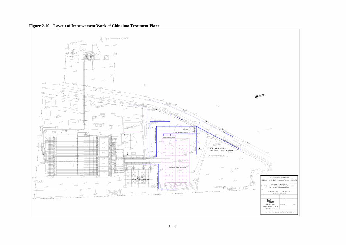
2 - 41
Figure 2-10 Layout of Improvement Work of Chinaimo Treatment Plant
AIR
VES
SEL O
700
Tran
smis
sion
Lin
e
BORDER LINE OF TRAINING CENTER (AFD)O
700
Planed Pumping Station
O700 Transmission Line
O600 Distribution Line
Flow Meter
By-
pass
O70
0
O20
0
Lao People's Democratic Republic
Ministry of Communication, Transport, Post and Construction
The Basic Design Study on
DATE
DRAWING NO.
APPROVED BY
DATEDESIGNED BY
TITLE:
SCALE:
TOKYO, JAPAN
NIHON SUIDO
Lao People's Democratic Republic
GENERAL PLAN OF CHINAIMO WTP
JAPAN INTERNATIONAL COOPERATION AGENCY
CONSULTANTS CO., LTD.
IMPROVEMENT PART
The Project for the Vientiane Water Supply Development in
Existing
O11
00 T
rans
mis
sion
Lin
e
Planed Clear Water Reservoir
Clear Water Reservoir
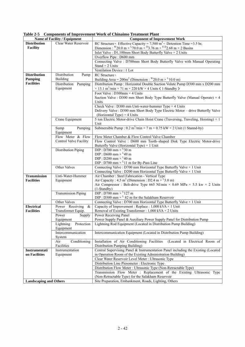
2 - 42
Table 2-5 Components of Improvement Work of Chinaimo Treatment Plant Name of Facility / Equipment Component of Improvement Work
RC Structure、Effective Capacity = 7,500 m3、Detention Time =3.5 hr, Dimension : W20.0 m × L70.0 m × D3.76 m × E.D2.68 m × 2 Basins Inlet Valve : D1,100mm Short Body Butterfly Valve × 2 Units Overflow Pipe : D600 mm Connecting Valve : D700mm Short Body Butterfly Valve with Manual Operating Stand × 2 Units
Distribution Facility
Clear Water Reservoir
Ventilation Device : 1 Lot Distribution Pump Building
RC Structure、 Building Area = 200m2 (Dimension : W20.0 m × L10.0 m) Distribution Pump : Horizontal Double Suction Volute Pump D300 mm x D200 mm × 13.1 m3/min × 71 m × 220 kW × 4 Units(1-Standby) Foot Valve : D300mm × 4 Units Suction Valve : D300 mm Short Body Type Butterfly Valve (Manual Operate) × 4 Units
Distribution Pumping Equipment
Check Valve : D300 mm Unti-water-hummer Type × 4 Units Delivery Valve : D300 mm Short Body Type Electric Motor – drive Butterfly Valve (Horizontal Type) × 4 Units
Crane Equipment 5 ton Electric Motor-drive Chain Hoist Crane (Traversing, Traveling, Hoisting) × 1 Unit
Sump Pumping Equipment
Submersible Pump : 0.2 m3/min × 7 m × 0.75 kW × 2 Unit (1 Stannd-by)
Flow Meter Chamber & Flow Control Valve Chamber Flow Meter & Flow Control Valve Facility Flow Control Valve : D600 mm Tooth–shaped Disk Type Electric Motor-drive
Butterfly Valve (Horizontal Type) × 1 Unit Distribution Piping DIP : D700 mm × L30 m
DIP : D600 mm × L49 m DIP : D200 mm × L40 m DIP : D700 mm × L11 m for By-Pass Line
Distribution Pumping Facilities
Other Valves Connecting Valve : D700 mm Horizontal Type Butterfly Valve × 1 Unit Connecting Valve : D200 mm Horizontal Type Butterfly Valve × 1 Unit
Unti-Water-Hummer Equipment
Air Chamber : Steel Fabrication - Vertical Type Air Capacity : 4.5 m3 (Dimension : D2.4 m × L3.0 m) Air Compressor : Belt-drive Type 665 Nl/min × 0.69 MPa × 5.5 kw × 2 Units (1-Standby)
Transmission Piping DIP : D700 mm × L127 m DIP : D300 mm × L 82 m for the Salakham Reservoir
Transmission Facilities
Other Valves Connecting Valve : D700 mm Horizontal Type Butterfly Valve × 1 Unit Power Receiving & Transformer Equip.
Capacity of Improvement : Replace : 1,000 kVA × 1 Unit Removal of Existing Transformer : 1,000 kVA × 2 Units
Power Supply Equipment
Power Receiving Panel Power Supply Panel & Auxiliary Power Supply Panel for Distribution Pump
Lightning Protection Equipment
Lightning Rod Equipment (Located in Distribution Pump Building)
Intercommunication System
Intercommunication Equipment (Located in Distribution Pump Building)
Electrical Facilities
Air Conditioning Facilities
Installation of Air Conditioning Facilities (Located in Electrical Room of Distribution Pumping Building) Central Supervising Panel & Instrumentation Panel including the Existing (Located in Operation Room of the Existing Administration Building) Clear Water Reservoir Level Meter : Ultrasonic Type Distribution Line Piesometer : Electronic Type Distribution Flow Meter : Ultrasonic Type (Non-Retractable Type)
Instrumentation Facilities
Instrumentation Equipment
Transmission Flow Meter : Replacement of the Existing Ultrasonic Type (Non-Retractable Type) for the Salakham Reservoir
Landscaping and Others Site Preparation, Embankment, Roads, Lighting, Others
2 - 43
2-2-2-6 Rehabilitation of Km6 Booster Pumping Station
The hydraulic network analysis indicated that the Km6 booster pumping station requires rehabilitation to
compliment the proposed improvements to the Chinaimo Treatment Plant, as described in the previous section.
The previous JICA M/P & F/S indicated that additional booster pumps for the transmission line would be required.
However because the GOL plans to implement the Dongmark Khay Project, these pumps will no longer be
required (the water will be transmitted from the Dongmark Khay treatment plant).
The existing booster pumps on the distribution line will be replaced by new pumps to distribute water around the
pumping station. The proposed layout of the rehabilitation/improvement of the Km6 booster pumping station is
shown on Figure 2-11.

2 - 44
Figure 2-11 Layout of Rehabilitation/Improvement of Km6 Booster Pumping Station
166.383
166.301
KM(DH01)
E 251225
43
RO2
166.440166.440
DRILLING HOLEEL :166.502 166.342
N 1991300
1
N: 1991330.628
E: 251228.705
EL: 166.963
KM6.2
166.500
166.560
166.501
N 1991325
�SP D350mm ( f80)(Existing)
E 251200
VICTORY GATEROAD No:13 SOUTH
THE LAO PEOPLE’S DEMOCRATIC REPUBLIC
N 1991325
E 2512501
CHECKED BY:DESIGNED BY:
DWG NO.:DATE:
DRAWN BY:
SCALE:
APPROVED BY:
NIHON SUIDO CONSULTANTS CO., LTD.
IMPROVEMENT OF Km6 BOOSTER PUMP STATION
JAPAN INTERNATIONAL COOPERATION AGENCY (JICA)
DRAWING TITLE:
GENERAL PLAN
166.344
166.498
166.500
166.293
166.428
VIENTIANE WATER SUPPLY DEVELOPMENT
PROJECT IN
THE STUDY ON
N: 1991342.180KM6.1
E: 251236.698EL: 166.964
166.518
166.381
166.784
�SP D350mm ( f80)(Exi
stin
g)�
SP D
300m
m (
f96)
E 251225
166.547 166.559
(Existing)
DONENOUNN 1991350
(Existing)
�DIP D200mm ( f80)
�SP
D30
0mm
(f96
)(E
xist
ing)
Distribution Pump
No. 3
Replacement of Distribution Pump
No. 2No. 1
PUMP STATION
PVC D150mm
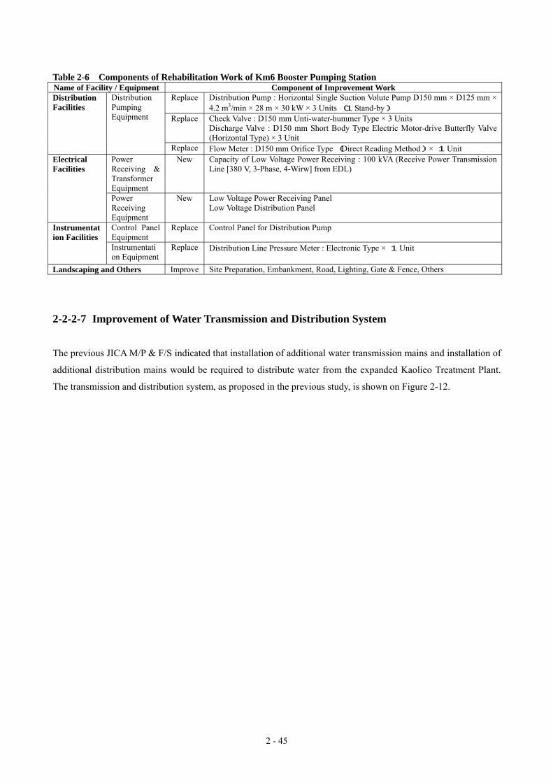
2 - 45
Table 2-6 Components of Rehabilitation Work of Km6 Booster Pumping Station Name of Facility / Equipment Component of Improvement Work
Replace Distribution Pump : Horizontal Single Suction Volute Pump D150 mm × D125 mm × 4.2 m3/min × 28 m × 30 kW × 3 Units (1 Stand-by)
Replace Check Valve : D150 mm Unti-water-hummer Type × 3 Units Discharge Valve : D150 mm Short Body Type Electric Motor-drive Butterfly Valve (Horizontal Type) × 3 Unit
Distribution Facilities
Distribution Pumping Equipment
Replace Flow Meter : D150 mm Orifice Type (Direct Reading Method) × 1 Unit Power Receiving & Transformer Equipment
New Capacity of Low Voltage Power Receiving : 100 kVA (Receive Power Transmission Line [380 V, 3-Phase, 4-Wirw] from EDL)
Electrical Facilities
Power Receiving Equipment
New Low Voltage Power Receiving Panel Low Voltage Distribution Panel
Control Panel Equipment
Replace Control Panel for Distribution Pump Instrumentation Facilities
Instrumentation Equipment
Replace Distribution Line Pressure Meter : Electronic Type × 1 Unit
Landscaping and Others Improve Site Preparation, Embankment, Road, Lighting, Gate & Fence, Others
2-2-2-7 Improvement of Water Transmission and Distribution System
The previous JICA M/P & F/S indicated that installation of additional water transmission mains and installation of
additional distribution mains would be required to distribute water from the expanded Kaolieo Treatment Plant.
The transmission and distribution system, as proposed in the previous study, is shown on Figure 2-12.

2 - 46
Figure 2-12 Transmission and Distribution System
(Previous JICA M/P & F/S)
Dongdok
Phonetong
Phonekheng
Phonethane
Samkhe
Km6
Chinaimo T.P.
Kaolieo T.P.
Existing Transmission Pipe
Distribution Pipe
Treatment Plant
Elevated Tank
Proposed Transmission Pipe
Nongteng
Naxaythong
The Donmark Khay project plans to transmit water to the Dongdok and Phoneton areas through proposed
transmission pipelines. This is expected to be completed before Japan’s Grant Aid Project (refer to Figure 1-1).
After completion of Japan’s Grant Aid Project, the water supply problems in the Phonetone area will be resolved
and therefore water transmission from Dongdok to Phonetone will not be required.
However, because the location of the Dongmark Khay treatment plant is in the north, it is proposed that the
northern parts of the city (including the Dondok area) be supplied from the Dongmark Khay treatment plant
continuously after the completion of the Japan’s Grant Aid Project.
The Dongmark Khay project consists of the following two packages.
Package 1
• Installation of an additional intake pump at the irrigation intake pump station on Namgum River.
• Construction of a new treatment plant (20,000 m3/day).
• Installation of a transmission pipeline to the Phonetone elevated tank via Dongdok reservoir (Dia. = 450mm;
2 - 47
L = 8.2km、 Dia = 400mm; L = 6.2km))
Package 2
• Installation of distribution mains and house connections.
After completion of the Dongmark Khay treatment plant and Japan’s Grant Aid Project, the total supply capacity
will be 160,000 m3/day.
Existing Chinaimo Treatment Plant : 80,000m3/day
Existing Kaolieo Treatment Plant : 20,000m3/day
Expansion of Kaolieo Treatment Plant : 40,000m3/day
New Dongmark Khay Treatment Plant : 20,000m3/day
TOTAL :160,000m3/day
The quantity of water to be supplied from the Dongmark Khay treatment plant to the northern parts of the existing
service area will be 12,000 m3/day as shown below.
Design capacity of Dongmark Khay treatment plant :20,000m3/day
Distribution at Dongmark Khay and to Tangone area : 3,000m3/day
Distribution to planned industrial estate : 5,000m3/day
Distribution to northern part of existing service area :12,000m3/day
Hydraulic network analysis was conducted to incorporate the scope of Package 1. The following conditions
were incorporated into the analysis:
• The network model that was developed during the previous JICA M/P & F/S was used. This model shows
that an additional 40,000 m3/day of water can be distributed from the expanded Kaolieo Treatment Plant.
• The Node discharge was calculated based on water demand in year 2010 because the total water supply
capacity is equivalent to the total water demand in 2010.
• It was assumed that 12,000 m3/day of water could be transmitted from the Dongmark Khay plant to the
Dongdok reservoir through the proposed transmission line. It was assumed that water would then be
distributed from the Dongdok reservoir.
• The existing transmission pipeline from Km6 Booster Pumping Station to Dongdok reservoir was used as the
distribution pipeline because transmission to the north was not required. The diameter of the transmission
pipeline is 300 mm.
• The proposed AFD project was not considered in the analysis because the timing of its implementation had
not been confirmed.

2 - 48
The contour line of the residual pressure within the distribution network (calculated by the network analysis) is
shown on Figure 2-13. Figure 2-14 presents a comparison of the network analyses undertaken for the:
• requested transmission/distribution system to/in the northern part of city by the GOL (proposed in the
previous JICA M/P & F/S); with
• revised project scope which includes consideration of the effects of water from the proposed Dongmark Khay
project.
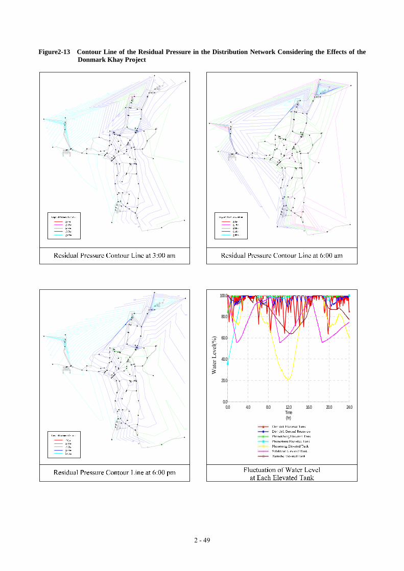
2 - 49
Figure2-13 Contour Line of the Residual Pressure in the Distribution Network Considering the Effects of the Donmark Khay Project
Time(hr)
(%)
Wa
ter
Lev
el
0.0
20.0
40.0
60.0
80.0
100.0
0.0 4.0 8.0 12.0 16.0 20.0 24.0
Wat
er L
evel
(%)

2 - 50
Figure 2-14 Transmission/distribution System to/in northern part of city requested by GOL compared with the Revised Scope which considers the Effects of the Dongmark Khay Project
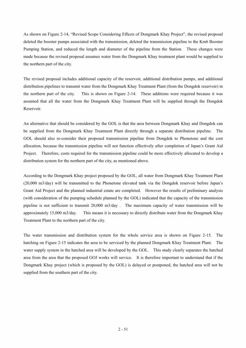
2 - 51
As shown on Figure 2-14, “Revised Scope Considering Effects of Dongmark Khay Project”, the revised proposal
deleted the booster pumps associated with the transmission, deleted the transmission pipeline to the Km6 Booster
Pumping Station, and reduced the length and diameter of the pipeline from the Station. These changes were
made because the revised proposal assumes water from the Dongmark Khay treatment plant would be supplied to
the northern part of the city.
The revised proposal includes additional capacity of the reservoir, additional distribution pumps, and additional
distribution pipelines to transmit water from the Dongmark Khay Treatment Plant (from the Dongdok reservoir) in
the northern part of the city. This is shown on Figure 2-14. These additions were required because it was
assumed that all the water from the Dongmark Khay Treatment Plant will be supplied through the Dongdok
Reservoir.
An alternative that should be considered by the GOL is that the area between Dongmark Khay and Dongdok can
be supplied from the Dongmark Khay Treatment Plant directly through a separate distribution pipeline. The
GOL should also re-consider their proposed transmission pipeline from Dongdok to Phonetone and the cost
allocation, because the transmission pipeline will not function effectively after completion of Japan’s Grant Aid
Project. Therefore, costs required for the transmission pipeline could be more effectively allocated to develop a
distribution system for the northern part of the city, as mentioned above.
According to the Dongmark Khay project proposed by the GOL, all water from Dongmark Khay Treatment Plant
(20,000 m3/day) will be transmitted to the Phonetone elevated tank via the Dongdok reservoir before Japan’s
Grant Aid Project and the planned industrial estate are completed. However the results of preliminary analysis
(with consideration of the pumping schedule planned by the GOL) indicated that the capacity of the transmission
pipeline is not sufficient to transmit 20,000 m3/day . The maximum capacity of water transmission will be
approximately 15,000 m3/day. This means it is necessary to directly distribute water from the Dongmark Khay
Treatment Plant to the northern part of the city.
The water transmission and distribution system for the whole service area is shown on Figure 2-15. The
hatching on Figure 2-15 indicates the area to be serviced by the planned Dongmark Khay Treatment Plant. The
water supply system in the hatched area will be developed by the GOL. This study clearly separates the hatched
area from the area that the proposed GOJ works will service. It is therefore important to understand that if the
Dongmark Khay project (which is proposed by the GOL) is delayed or postponed, the hatched area will not be
supplied from the southern part of the city.