basic design of flying wing models
DESCRIPTION
flying wing designTRANSCRIPT

BASIC DESIGN OF FLYING WING MODELS

Basic Design of Flying Wing Models
Preface
A survey of the available literature on the topic of flying wing and tailless model airplanes shows, that in most cases, the airfoil selection is mentioned, but no reliable data for the selection are available. Due to the dedicated work of various modelers, a huge collection of airfoil coordinates is available today [UIUC], [Bender/Wiechers] - a comparable set of aerodynamic data is more difficult to find, though. This situation and, the numerous questions of modelers, concerning the performance and the selection of airfoils for flying wing models, initiated this paper. On this web page, you will find a way to perform the necessary calculations for stable flying wing models. The accompanying collection of airfoil coordinates and polars has been published in [29].
An indoor flying wing model by R. Eppler in 1942.
Airfoils for Flying Wings
Tailless planes and flying wings can be equipped with almost any airfoil, if sweep and twist distribution are chosen accordingly. Thus, the one and only "flying wing airfoil" does not exist. However, if we want to design a tailless plane with a wide operating range, the wing should have a small amount of twist only, or none at all, to keep the induced drag at reasonable levels throughout the whole flight envelope. Under these conditions, the wing must not create a large variation in moment coefficient, when the angle of attack is varied. This makes it necessary, to use airfoils with a low moment coefficient. In the case of an unswept wing ("plank"), even an airfoil with a positive moment coefficient is necessary, to avoid upward deflected flaps under trimmed flight conditions. Such airfoils usually have a reflexed camber line.
A modern radio controlled F3B flying wing model of 1994.

Longitudinal Stability
Like its full sized cousins, each model airplane should have a minimum amount of stability, i.e. it should be able to return to its trimmed flight condition after a disturbance by a gust or a control input. How much stability is required, depends on the pilots personal taste: contest pilots prefer a small stability margin, beginners like to fly with a large margin. Here, only a brief introduction into the topic will be given, which will make it possible to find a first guess for the center of gravity and a reasonable combination of sweep and camber for a flying wing.
1. Unswept Wings (Plank)
While the horizontal tailplane provides the necessary amount of longitudinal stability on a conventional plane, it is the wing, which stabilizes an unswept wing. In most cases, airfoils with reflexed (s-shaped) mean lines are used on flying wing models to achieve a longitudinally stable model.
Some important Aerodynamic and Mechanical Facts
To understand, why a reflexed airfoil is able to provide longitudinal stability to a wing, two things are important:
Total Force and Moment, c/4 point
The pressure forces, which act on the surface of each wing section, can be replaced by a single total force and a single total moment. Both act at the quarter-chord point of the airfoil. When the angle of attack changes (e.g. due to a gust), the moment stays nearly constant, but the total force changes. Increasing the angle of attack increases the force.
Center of Gravity
Translations and rotations of "free floating" bodies are performed relative to their center of gravity. When the angle of attack of a plane changes, the plane rotates (pitches) around its center of gravity (c.g.).
Equilibrium
Let's have a look at a trimmed flight condition, where all forces and moments are in equilibrium and let's compare a conventional, cambered airfoil with an airfoil with a reflexed camber line. The moments and forces for this trimmed state are denoted with an asterisk (*). The forces are the weight of the model m, multiplied with the gravity acceleration g (9.81m/s) and the aerodynamic lift L, which have to cancel out (sum of forces in vertical direction equals zero). The drag forces are neglected here. The sum of the moments around c.g. (caused by the airfoil moment M and the lift force L, acting at a distance from c.g.) must also be zero.

conventional airfoil with camber airfoil with reflexed mean line
Equilibrium State
This airfoil has a nose heavy moment. As stated above, the center of gravity is also the center of rotation of the wing. When it is shifted behind the c/4 point, the air force L* in front of the c.g. counteracts the nose heavy moment M* to achieve equilibrium. The distance between c.g. and c/4 point is depending on the amount of M*. A symmetrical airfoil has M*=0, which means we have to place the c.g. at the c/4 point.
The reflexed camber line makes the moment coefficient positive, which means, that the moment around the c/4 point is working in the tail heavy direction. Therefore the center of gravity has to be located in front of the c/4 point to balance the moment M* by the lift force L*. The larger the moment (-coefficient) of the airfoil, the larger the distance between c/4 and the c.g. for equilibrium.
Disturbed State
When the angle of attack is increased (e.g. by a gust), the lift force L increases. Now L>L* and the tail heavy moment due to the lift is larger than the moment around c/4, which still is M=M*. Thus the wing will pitch up, increasing the angle of attack further. This behavior is instable and a tailplane is needed to stabilize the system.
Here, we have the air force acting behind the c.g., which results in an additional nose heavy moment, when the lift increases. With L>L*, the wing will pitch down, reducing the angle of attack, until the equilibrium state is reached again. The system is stable.
Neutral Point and Stability
As we learned above, an unswept wing with a reflexed airfoil is able to stabilize itself. Its c.g. must be located in front of the c/4 point, which is also called neutral point (n.p.). The distance between the neutral point (quarter chord point for an unswept wing) and the center of gravity is defining the amount of stability - if the c.g. is close to the n.p., the straightening moment is small and the wing returns (too) slowly into its equilibrium condition. If the distance c.g. - n.p. is large, the c.g. is far

ahead of the c/4 point and the wing returns quickly to the equilibrium angle. You will require larger flap deflections to control the model, though. If the distance is too large, the wing may become over-stabilized, overshooting its trimmed flight attitude and oscillating more and more until the plane crashes.
A measure for stability is the distance between c.g. and n.p., divided by the mean chord of the wing. Typical values for this number for a flying wing are between 0.02 and 0.05, which means a stability coefficient sigma of 2 to 5 percent. We can express
the equilibrium of moments around c.g. for our design lift coefficient by
,
which can be transformed to find the moment coefficient needed to satisfy a certain stability coefficient:
.
Example We want to use an unswept flying wing (a plank) for ridge soaring and decide to use a
target lift coefficient of =0.5. We want to have a stability coefficient of 5% and are looking for a matching airfoil. We calculate the necessary moment coefficient
Cm = 0.5 * 0.05 = +0.025.
Searching through a publication about Eppler airfoils [28], we find, that the airfoils E 186 and E 230 could be used for our model.
2. Swept Wings
2.1 Neutral Point and Stability
We have already learned, that the center of gravity must be located in front of the neutral point. While the n.p. of an unswept, rectangular wing is approximately at the c/4 point, the n.p. of a swept, tapered wing must be calculated. The following procedure can be used for a simple, tapered and, swept wing. First, we calculate the
mean aerodynamic chord length of a tapered wing, which is independent from the sweep angle:
with the root chord lr, the tip chord lt and the taper ratio .
We can also calculate the spanwise location of the mean chord , using the span b,

.
The n.p. of our swept wing can be found by drawing a line, parallel to the fuselage
center line, at the spanwise station y. The chord at this station should be equal to . The n.p. is approximately located at the c/4 point of this chord line (see the sketch below).
Geometric parameters of a tapered, swept wing.
Instead of using the graphical approach, the location of the neutral point can also be calculated by using one of the following formulas, depending on the taper ratio:
, if taper ratio > 0.375
, if taper ratio < 0.375.
The c.g. must be placed in front of this point, and the wing may need some twist (washout) to get a sufficiently stable wing.
2.2 Twist
The selection of the location of the c.g. to be infront of the n.p. is not a guarantee for equilibrium - it is only a requirement for longitudinal stability. Additionally, as explained above for unswept wings, the sum of all aerodynamic moments around the c.g. must be zero. Because we have selected the position of the c.g. already to satisfy the stability criterion (c.g. in front of n.p.), we can achieve the equilibrium of the moments only by airfoil selection and by adjusting the twist of the wing. On conventional airplanes with a horizontal stabilizer it is usually possible to adjust the difference between the angles of incidence of wing and tailplane during the first flight tests. On the other hand, flying wings have the difference built into the wing

(twist), which cannot be altered easily. Thus it is very important to get the combination of planform, airfoils and twist right (or at least close) before the wing is built. Again, the calculation of these parameters is quite complex and shall not be presented here; the relations are shown in great detail in [27]. Here I will present a simple, approximate approach, which is based on two graphs, and can be used for swept, tapered wings with a linear airfoil variation from root to tip.
We start with the same geometric parameters, which we have used for the calculation of the n.p. above. Additionally, we calculate the aspect ratio (AR = b²/S, where S is the wing area) of the wing. The selection of the airfoil sections also defines the operating range of the model. Airfoils with a small amount of camber are not well suited for slow, thermaling flight, but good for F3B flight style and ridge soaring. We can design the twist distribution for one trimmed lift coefficient, where the wing will fly without flap deflections. This lift coefficient will usually be somewhere between the best glide and the best climb performance of the airfoil. With the selected lift coefficient Cl of the airfoils, we can also find the moment coefficient Cm0.25 from the airfoil polars. If we plan to use different root and tip sections, we use the mean value of the moment coefficient of the two airfoils. The required twist of the wing can be combined from two parts:
Geometric Twist This is the twist, which is built into the wing as the difference between the x-axis of the root and the tip section. It corresponds to the angle difference between main wing and tailplane of conventional planes and can be easily measured. A positive twist means a smaller angle of incidence at the tip section (washout). Large geometric twist angles can be used to stabilize wings with small sweep angles or highly cambered airfoils, but have the drawback of creating large amounts of induced drag, when the wing is operated outside of its design point. The aim of the following paragraphs is to find the geometric twist.
Aerodynamic Twist
If we select airfoils with different zero lift angles, we can reduce the amount of geometric twist. The difference between the zero lift directions is called aerodynamic twist and we need airfoil polars to find the zero lift angle. Also, a small or even positive moment coefficient reduced the required amount of geometric twist, and improves the off design performance of the wing.
Finding the Required Twist ßreq
Using graph 1, we enter the graph with the aspect ratio AR on the horizontal axis, and draw a vertical line upwards, until we intersect the curve, corresponding to the sweep angle of the c/4 line. Continuing to the axis on the left border, we find the standard value *req for the required twist angle.This standard value is valid for a wing, which:
is trimmed at = 1.0 and, has a stability coefficient of * =10% (see above), and
uses airfoils with a moment coefficient of zero.

From the standard value we calculate the true, required twist angle, using the formula inset into the graph. Therefore, we calculate the ratio of our target lift
coefficient to the standard lift coefficient (CL/ ) and the ratio of our desired
stability coefficient to the standard . We see, that a reduction of the lift coefficient to CL=0.5 also reduces the required twist by 50%. Also, if we use a smaller stability margin , we need a smaller amount of twist.
Graph 1: Finding the required twist.
Variation of zero lift angle
If we use different airfoils at root and tip, they may have different zero lift directions, which influences the equilibrium state. The geometric twist has to be reduced by the difference of the zero lift directions 0 of tip and root sections:
.
Using the same airfoil for both sections, we can set 0 to zero.
Influence of the Airfoil Moment coefficients
The moment coefficient of the airfoils contributes to the equilibrium, and has to be taken into account for the calculation of the twist. Graph 2 can be used to find the equivalent twist due to the contribution of Cm, which has to be subtracted from the required twist. If we use airfoils with positive moment coefficients, the contribution will be positive, which results in a reduction of the amount twist, highly cambered airfoils yield negative values Cm, which force us to build more twist into the wing. Similar to the previous graph, we enter with the aspect ratio, intersect with the sweep curve and read the value for Cm from the lefthand axis.

Graph 2: Finding the additional twist due to the airfoils moment coefficient.
Again, the graph has been plotted for a certain standard condition, which is a moment coefficient of cm* = 0.05 (note: positive value). We apply the ratio of the moment coefficients (cm/cm*) to find the contribution Cm of the moment coefficient to the geometric twist. This contribution has to be subtracted from the required twist angle, too. Using the usual, cambered airfoils with negative moment coefficients will change the sign of the ratio cm/cm
*, which results in negative Cm values. This means,
that the subtraction from req will actually be an addition, increasing the geometric twist angle. If we have different airfoils at root and tip, we can use the mean moment coefficient (cm,tip + cm,root)/2 to calculate the ratio cm/cm
*.
Finally, we can calculate the geometric twist angle geo, which has to be built into the wing:
.
Example As you have noticed, the graphs contain an example, which is used here. We consider a flying wing model with the following data:
wing span b = 2.365 m
chord length at root lr = 0.260 m
chord length at tip lt = 0.170 m
sweep angle at c/4 line 0.25 = 20°
design lift coefficient CL = 0.5
root section E 182 cm,r = +0.01 and 0,r = -0.3°
tip section E 184 cm,t = +0.03 and 0,t = 0.5°
desired stability coefficient sigma = 0.05

We calculate the wing area S:
S = (l_r + l_t)/2 * b = 0.5085 m²
and the aspect ratio
AR = b²/S = 11.0
and the mean moment coefficient
cm = (cm,r + cm,t)/2 = 0.02 .
Using graph 1, we find *req = 11.8°, which has to be corrected to match our design lift
coefficient and the desired stability margin:
11.8 * (0.5/1.0) * (0.05/0.1) = 2.95° .
This means that our model would need a twist angle of 2.95° (wash out) from root to tip, if we would use a symmetrical airfoil section.
The difference of the zero lift angle of tip and root section is
.
Now we read the twist contribution of the moment coefficient from graph 2, which is *
Cm = 5.8°, which has to be corrected for our smaller mean moment coefficient:
5.8 * (0.02/0.05) = 2.32° .
Finally, we calculate the geometric twist from
2.95° - 0.8° - 2.32° = -0.17° .
The negative value means, that we could use a small amount of wash-in! This is because we have already enough stability due to the selection of airfoils with reflexed camber lines. Since the calculated amount is very small, we can use the same angle of incidence for the root and tip ribs. Since the presented method is not perfect, we can assume an accuracy to 1 degree, which is also a reasonable assumption for the average building skills.

BibliographyYes, lots of German references, but there are at least some papers in English below...
1. Hepperle, Martin: Neue Profile für Nurflügelmodelle, FMT-Kolleg 8, Verlag für Technik und Handwerk, Baden-Baden, Germany, 1988.
2. Unverfehrt, Hans-Jürgen: Faszination Nurflügel, Verlag für Technik und Handwerk, Baden-Baden, Germany, 1990.
3. Hepperle, Martin: Neue Profile für Elektro-Pylonmodelle, FMT-Kolleg 10, Verlag für Technik und Handwerk, Baden-Baden, Germany, 1991.
4. Hepperle, Martin: Neue Profile für Pylon und Speed, FMT 6, Verlag für Technik und Handwerk, Baden-Baden, 1986.
5. Jakob, Otto: Eppler 220 und Eppler 221, FMT 2, Verlag für Technik und Handwerk, Baden-Baden, 1985.
6. Hepperle, Martin: Neue Profile für schnelle Flugmodelle, FMT-Kolleg 17, Verlag für Technik und Handwerk, Baden-Baden, 1994.
7. Hepperle, Martin: Segelflugmodell Wizzard mit Profil MH 42, FMT 2, Verlag für Technik und Handwerk, Baden-Baden, 1988.
8. Anderson, D. A.: Introduction to Flight, 3rd edition, McGraw-Hill, 1989, ISBN 0-07-100496-3.
9. Horjesí, Milan: Aerodynamika Létajících Modelu, Nase Vojsko, Praha, 1957. 10. Adkins, C. N.: Design of Optimum Propellers, AIAA-83-0190. Also published in the
Journal of Propulsion and Power, Vol. 10, No. 5, September-October 1994. 11. Larrabee, E. E.: Practical Design of Minimum Induced Loss Propellers, SAE paper 790585,
Business Aircraft Meeting and Exposition, Wichita, April 1979. 12. Hansen, H.: Windkanalmessungen im Reynoldszahlbereich von Modellflugzeugen, FMT-
Kolleg 6, Verlag für Technik und Handwerk, Baden-Baden, Germany, 1989. 13. Mueller, T. et al.: Low Reynolds Number Wind Tunnel Measurements: The Importance of
being Earnest, Conference on Aerodynamics at Low Reynolds Numbers, London, 1986. 14. Eppler, R. and Somers, D.: A Computer Program for the Design and Analysis of Low-Speed
Airfoils, NASA TM-80210, 1980. 15. Eppler, R.: Praktische Berechnung laminarer und turbulenter Absauge-Grenzschichten,
Ingenieur-Archiv. 16. Eppler, R.: Turbulent Airfoils for General Aviation, Journal of Aircraft, Vol. 15, No. 2,
1978. 17. Guglielmo, J. and Selig, M.: Spanwise Variations in Profile Drag for Airfoils at Low
Reynolds Numbers, Journal of Aircraft, Vol. 33, No. 4, 1996. 18. Felske, U. und Seubert, R.: Profilmessung bei kleinen Reynoldszahlen im Modellwindkanal,
Studienarbeit, Institut für Aero- und Gasdynamik, Universität Stuttgart, 1983. 19. Anderson, J. D.: Fundamentals of Aerodynamics, 2nd Edition, McGraw-Hill, 1991, ISBN 0-
07-100767-9. 20. Althaus, D.: Profilpolaren für den Modellflug, Neckar-Verlag, Villingen-Schwenningen. 21. Selig, M. S., Donovan, J. F., Fraser, D. B.: Airfoils at Low Speeds, Soartech 8, 1989. 22. Krause, B.: Modellmotorentechnik, transpress VEB, Berlin, 1986. 23. Jennings, G.: Two-Stroke Tuner´s Handbook, H.P. Books(?) 1973. 24. Bönsch, H. W.: Der schnellaufende Zweitaktmotor, Motorbuch Verlag, Stuttgart, 1982. 25. Lyon, C., Selig, M. S., Broeren, A.: Boundary Layer Trips on Airfoils at Low Reynolds
Numbers, AIAA 97-0511, 1997. 26. Katz, J., Plotkin, A.: Low-Speed Aerodynamics, McGraw-Hill, 1991, ISBN 0-07-100876-4.

27. Nickel, K., Wohlfahrt, M.: Schwanzlose Flugzeuge, Birkhäuser Verlag, 1990, ISBN 3-7643-2502-X, also available in english as: Tailless Aircraft in Theory and Practice, AIAA Education Series, ISBN 1-563-47094-2.
28. Hepperle, M.: Eppler-Profile, MTB 1/2, Verlag für Technik und Handwerk, Baden-Baden, 1986, ISBN 3-88180-100-6.
29. Hepperle, Martin: Profile für Nurflügelmodelle, FMT-Kolleg 20, 21, and 22, Verlag für Technik und Handwerk, Baden-Baden, Germany, 1997.
30. Selig, M., Guglielmo, J., Broeren, A., Giguère, P.: Summary of Low-Speed Airfoil Data, Volume 1, SoarTech Publications, Virginia Beach, 1995, ISBN 0-9646747-1-8
31. Selig, M., Lyon, C., Giguère, P., Ninham, C., Guglielmo, J.: Summary of Low-Speed Airfoil Data, Volume 2, SoarTech Publications, Virginia Beach, 1996, ISBN 0-9646747-2-6
32. Sabbagh, K.: 21st Century Jet - The Making of the Boeing 777, Pan Books, 1996, ISBN 0-330-32890-5.
33. Lennon, A.: R/C Model Aircraft Design, AirAge Publishing (MAN), 1006, ISBN 0-911295-40-2
34. Abbott, I.H., von Doenhoff, A.E.: Theory of Wing Sections, Dover Publications, New York, 1959, SBN: 486-60586-8.
35. Cebeci, T.: An Engineering Approach to the Calculation of Aerodynamic Flows, Springer1999, ISBN 3-540-66181-6
Airfoils for Tailless Airplanes:Design and SelectionRemark:The following paper is a summary of a presentation, given on the 13th October 1991, at the 8th Nurflügelsymposium (tailless planes symposium) of the Oskar-Ursinus-Vereinigung (OUV, a german amateur aircraft builder association), in Scheidegg, Germany.
Airplane Types and Moment Coefficient Moment Coefficient and Airfoil Shape Reflex and Moment Coefficient Reflex and Lift & Drag Location of Camber and Moment Coefficient Velocity Distribution and Boundary Layer Dangers everywhere Airfoil Design for Light Tailless Airplanes Conclusions

Airplane Types and Moment Coefficient
Besides lift and drag coefficients, the moment coefficient cm is of importance for the behaviour of an airplane - it has a big impact on the longitudinal stability. While a conventional airplane can compensate the moment of the wing with its horizontal tail, a tailless plane obviously can't.
It is possible to divide tailless airplanes in three groups, depending on how they achieve longitudinal stability. The requirements for the moment coefficient of the airfoil is a direct result of the stabilizing mechanism.
wing without sweep (plank)Longitudinal stability is created solely by the airfoil. A plank requires an airfoil with a positive moment coefficient.
swept wingIt is possible to use any airfoil, because longitudinal stability can always be achieved by selecting a suitable combination of sweep and twist. For best allround performance, airfoils with low moment coefficients (around zero) are better suited although. They need smaller amounts of twist, which results in a broader speed range without paying too much penalties off the design point.
wing with a low position of the center of gravity (parafoil)The moment coefficient is less important and it is possible to use traditional airfoils with negative moment coefficients. The position of the c.g. can be chosen to guarantee stability, but usually airfoils with medium moment coefficients are chosen to achieve higher penetration speeds and a wider speed range.
Classes of tailless airplanes and their typical moment coefficients.
Remark:To achieve static longitudinal stability, the center of gravity (c.g.) must be located in front of the neutral point, which makes the momentum derivative dCm/dAlfa (rel. c.g.) negative. Placing the c.g. in the neutral point results in dCm/dAlfa = 0, making the plane indifferent, i.e. it will not stabilize itself after a disturbance. These requirements lead to the moment coefficients presented above.To achieve dynamic stability oscillations must be damped out, which can be difficult, when the c.g. is located too far ahead of the neutral point and the moments of inertia around a spanwise axis are small (as with an unswept flying wing).

Airplane Types and Moment Coefficient Moment Coefficient and Airfoil Shape
Airfoils for Tailless Airplanes: Design and Selection
Airplane Types and Moment Coefficient Moment Coefficient and Airfoil Shape Reflex and Moment Coefficient Reflex and Lift & Drag Location of Camber and Moment Coefficient Velocity Distribution and Boundary Layer Dangers everywhere Airfoil Design for Light Tailless Airplanes Conclusions
Moment Coefficient and Airfoil Shape
The shape of an airfoil can always be thought of being composed of two parts: a camber distribution (camber line) and a thickness distribution, which is distributed along the camber line. The requirements for the three classes of tailless planes can be translated in corresponding airfoil shapes and wing twist distributions. The only way to achieve a positive moment coefficient and the required amount of lift is to use a S-shaped camber line, which is also called a reflexed camber line.
wing without sweep (plank)A positive moment coefficient results in a reflexed camber line. A twist does not help for stability, but can improve the stall characteristics of the wing.
swept wingLow moment coefficients and a small amount of twist can be achieved by airfoils with little camber and a neutral or slightly reflexed camber line.
wing with a low position of the center of gravity (parafoil)The moment coefficient poses no strong restriction on the airfoil shape.
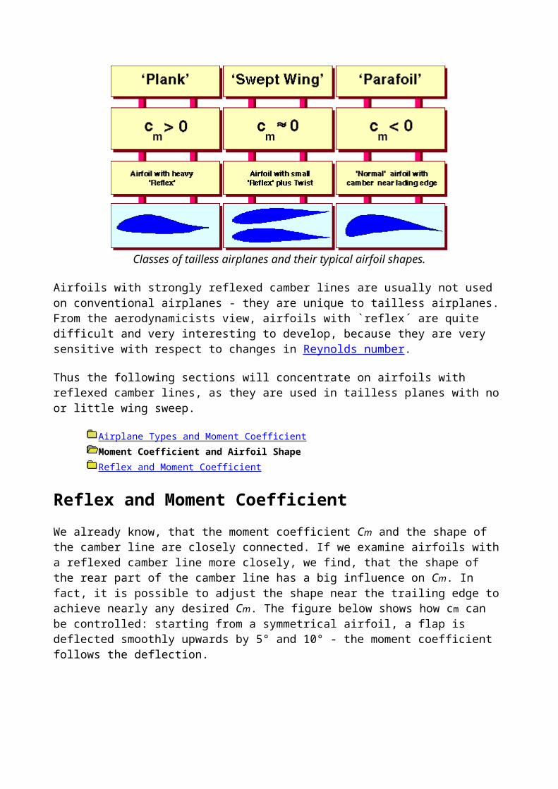
Classes of tailless airplanes and their typical airfoil shapes.

Airfoils with strongly reflexed camber lines are usually not used on conventional airplanes - they are unique to tailless airplanes. From the aerodynamicists view, airfoils with `reflex´ are quite difficult and very interesting to develop, because they are very sensitive with respect to changes in Reynolds number.
Thus the following sections will concentrate on airfoils with reflexed camber lines, as they are used in tailless planes with no or little wing sweep.
Airplane Types and Moment Coefficient Moment Coefficient and Airfoil Shape Reflex and Moment Coefficient
Reflex and Moment Coefficient
We already know, that the moment coefficient Cm and the shape of the camber line are closely connected. If we examine airfoils with a reflexed camber line more closely, we find, that the shape of the rear part of the camber line has a big influence on Cm. In fact, it is possible to adjust the shape near the trailing edge to achieve nearly any desired Cm. The figure below shows how cm can be controlled: starting from a symmetrical airfoil, a flap is deflected smoothly upwards by 5° and 10° - the moment coefficient follows the deflection.
The plot of moment coefficient vs. angle of attack shows,how cm depends on the amount of reflex.
Using this trick, the problem seems to be solved. We simply bend the railing edge upward until we achieve the moment coefficient necessary to stabilize our tailless plane and there we go...
But we probably prefer an airplane, which not only flies safe and stable, but also performs with a low sink speed, a high penetration speed and a good L/D ratio - that's where all the trouble begins.
Reflex and Lift & Drag
The shape and location of the lift and drag polar of the airfoil is the key to airplane performance. The images below show, how the cd-cl polar changes, when the camber line gets reflexed.

Lift vs. drag coefficients for different amounts of reflex.
Now we have a problem: while we add reflex to the camber line, in order to shift the moment coefficient towards the positive values, we shift the lift vs. drag polar down. This means, that we actually reduce the lift at a certain angle of attack and, what's even worse, we also reduce the maximum lift coefficient. A reduced maximum lift coefficient leads to higher stall and landing speeds, which is not exactly our aim. Of course the aerodynamicist already knows a remedy against low lift: he increases the amount of the maximum camber. Indeed, this increases the lift, but also reduces the positive moment coefficient.
Location of Camber and Moment Coefficient
Luckily, there is still one parameter left to compensate for the destabilizing effect of increased camber - it is the location of the maximum camber. Its location has a small influence on the lift vs. drag polar, but a strong impact on the moment coefficient. Below, the moment coefficient vs. the angle of attack for a family of airfoils is shown. The airfoils differ in the location of the maximum camber xc/c.
Influence of the location of the camber (xc/c) on the moment coefficient.

As we can see, moving the location of the maximum camber backwards, also shifts the moment coefficient down towards negative values. Thus it might be advisable, to concentrate the camber in the first quarter of the chord length, if we want to compensate the lift loss (introduced by the reflexed camber line) by an increased amount of camber.
Dangers everywhere
We have already learned, that several parameters, linked closely together, have an influence on the design of a low moment, high lift airfoil. We have not yet talked about the additional problems, introduced by the behavior of the boundary layer.
Problems facing the designer of an airfoil for tailless airplanes.
The Figure above and the enumeration below show the most important parameters and how they are linked together.
Moving the maximum camber towards the leading edge+ more stable moment coefficient (more positive).- puts more stress on the boundary layer near the leading edge (suction peaks).
Increasing the amount of camber+ better lift (cl vs. cd shifts towards positive cl values).+ cl-max may be increased.- less stable moment coefficient (more negative).- puts more stress on the boundary layer (more pressure drop towards the trailing edge).
Increasing the amount of reflex+ more stable moment coefficient (more positive).- less lift (cl vs. cd shifts towards negative cl values).- cl-max decreases.
Velocity Distribution and Boundary Layer
To shed more light on the boundary layer problems, we will have a look at velocity distributions of airfoils with reflexed camber lines.

How camber and reflex change the velocity distribution.
The image above presents velocity distributions of four different airfoils with different combinations of reflex and camber. The moment coefficient of all airfoils is similar.
In general, the velocity distributions of the upper surfaces show high velocities in the first third of the chord length, steadily decreasing as the flow reaches the trailing edge. Depending on the Reynolds number, the steepness of the velocity drop (which, according to Bernoulli's equation, represents a pressure rise) is limited. When the pressure rise is too strong, the flow separates, causing loss of lift and increasing drag.
The velocity distribution on the lower surface pose less problems, with a danger for boundary layer separation near the trailing edge. This will have a destabilizing effect and will cause an increase in drag.
A unique feature of airfoils with a reflexed camber line is the crossover of the velocity distributions in the second half of the chord length. Increasing the amount of reflex, speeds up the flow on the lower surface, while it slows down the flow on the upper side. The enclosed area of negative lift near the trailing edge increases, driving the moment coefficient towards positive (more stable) values.
Increasing the camber will increase the velocity on the upper surface and decrease the speed on the lower surface. The enclosed area of positive lift in the front half of the airfoil also increases, contributing to the lift. When the camber is increased too much, the maximum lift may decrease, because the camber has to be compensated by a larger amount of reflex, putting more stress on the boundary layer. Typically, the maximum lift can be increased to a certain amount, by increasing camber and reflex, but at the cost of a harder stall, which might be dangerous during takeoff and landing.
Airfoil Design for Light Tailless Airplanes
Smaller tailless airplanes, like ultra light and foot launched gliders should be designed with a larger safety margin regarding stall speed and stall behavior. Due to their low flight speed, the are responding lively to guests during the takeoff and landing phase, which may cause large angle of attack variations. Additionally they operate in a Reynolds number range between 200'000 and 1 million, where the boundary layer has a strong impact on airfoil performance and behavior.

First we will have a look at two existing airfoil sections, which have been used in man carrying tailless airplanes. The first one is a modern airfoil (FX 05-H-126) with a reflexed camber line, which was not designed for amateur built tailless planes, but for helicopter blades. Nevertheless it has been used in some amateur projects, by people seeking for maximum performance. The second airfoil (Horten II) has been designed for light tailless planes, but is much older, having been designed in the 1930s.
FX 05-H-126
This airfoil has been designed by F. X. Wortmann during a stay at the Bell helicopter company in the USA.
Velocity distribution of the FX 05-H-126 airfoil at 3 different angles of attack.The design point corresponds approximately to the middle of the three curves.
The velocity distribution shows a typical low speed laminar flow airfoil. The velocity on the upper surface increases steadily to 50% chord length, where a rather steep, concave velocity drop starts. The velocity on the lower surface is nearly constant, slightly increasing towards the trailing edge. Such a distribution results in laminar flow over the first half of the airfoils upper surface and along the total length of the lower surface. The drag polar, shown below, indicates the benefits and the problems of such a velocity distribution: very low drag and good performance, but only in a narrow range of lift coefficients (laminar bucket). Outside of the bucket, the drag increases rapidly and the danger of flow separation at low Reynolds numbers is quite high. The airfoil has a hard stall behavior and suffers from flow separation at Reynolds numbers below 2 millions. For an amateur built, light tailless glider, it is probably not a good choice (but well suited for the blade of a helicopter rotor).
Drag polars of the FX 05-H-126 airfoil.
Horten II
As a reminiscence to the past, this airfoil is astonishingly well suited for our purpose. Originally this airfoil had been designed and used by the Horten brothers, who built a number of high performance sailplanes during the 1930s and 1940s. Their designs are legend, although some of their published performance data are a little bit too good. There planes were well known for their good handling characteristics, which can be of greater importance that the actual performance figures of a sailplane.
Velocity distribution of the Horten airfoil at 3 different angles of attack.
The velocity distribution of the Horten II airfoil looks quite different from the FX airfoil. The distribution on the upper surface, is much smoother. Due to the blunt leading edge, no suction peaks are visible for the selected angles of attack. The pressure rise (velocity drop) starts near 20% of the chord length, which leads to a less steep gradient. The lift vs. drag characteristics shows smoother polars with no distinctly separated low drag region. The airfoil does not reach the low drag of the FX airfoil.
Drag polars of the Horten II airfoil.
The stall characteristics of the Horten II airfoil are smoother than the FX 05-H-126 airfoil, but due to its excessive thickness, it also suffers from boundary layer separation at lower Reynolds numbers. Its moment coefficient is not positive enough for an unswept flying wing. A thinned version of this airfoil with a slightly increased reflex, might be usable for a light, tailless glider.
Instead of trying to modify an existing airfoil a new design has been performed to find a compromise between performance and handling.

MH 78
During the design of this airfoil, the emphasis has been to design an airfoil, suited for light, man carrying gliders, with moderate wing sweep. While performance was an issue, maximum lift capabilities and good handling qualities were more important. Regarding the usual construction techniques, it was decided to allow transition on the upper surface near 15% of the chord length. The blunt leading edge and the smooth movement of the trailing edge separation is responsible for the comfortable stall characteristics. Flight Reynolds numbers can start at 400'000, where the maximum lift coefficient is approximately 1.4.
Velocity distribution of the MH 78 at 3 different angles of attack.
Lift vs. drag polars of the MH 78.
Conclusions
Depending on the type of tailless airplane, stability requirements lead to different criteria for airfoil selection. For most tailless planes, airfoils with low moment coefficients yield the best performance. Low moment coefficients and high lift coefficients can be achieved by using reflexed camber lines, but the corresponding velocity distributions are sensitive to low Reynolds numbers, and may result in problems with stall behavior. The best compromise for light, tailless airplanes seems to be a moderately reflexed camber line, combined with the maximum camber shifted towards the leading edge and a rather blunt nose. Together with a smooth velocity distribution, a soft stalling character can be achieved. Concerning the stall characteristics, the airfoil plays an important role, but only in conjunction with the spanwise lift distribution, which is a result of the wing planform and the spanwise twist distribution. Swept and tapered wings tend to have a higher loading near the wing tip, which causes the tip to stall first, if no additional twist is used.
Alas c0n baja relacion de aspecto

Wings of low aspect-ratio are known for having poor aerodynamic efficiency L/D at low speeds, along with stability problems, both static and dynamic.
The high angle of attack stall of the low aspect-ratio wings has been known since the early days of aerodynamics. Why short wings, then ? - There can only be practical limitations to use such wings.
The most interesting case is the wing-in-ground ship (AR = 1 ÷ 3); there are also short wings in racing cars (typical aspect ratios AR < 3); short wings are also part of control devices in competition sailing boats and micro air vehicles. Low aspect ratios (about 2 ÷ 3) in fighter aircraft are necessary to maintain a high degree of manouvrability, though at the expense of some stability (see below).
We define a low aspect-ratio wing a wing having AR < 5. Squared wings and wings with even lower aspect ratios are still interesting from a theoretical point of view, but of uncertain application.
Theoretical analysis was performed by Betz in the 1920s. Later a number of non-linear lifting line theories (Multhopp, Gersten, Truckenbrodt, and others) provided simple means to predict the vortex lift created by the leading edge separation.
Fig. 1 below shows a qualitative example of how strong an influence the leading edge vortex can have on the lifting characteristics of a short wing.
Figure 1: Lift characteristics at very low aspect-ratios
Wing Performance at Low Speeds
Short wings for low speeds have been studied for a long time. The high angle of attack stall of the low aspect-ratio wings has been known since the early days of aerodynamics. Handley-Page (1911) found that a squared wing (AR=1) stalled at angles above 40 degrees, while a moderately slender wing (AR=6.25) stalled at incidences as low as 10 degrees.
Experimental Data
A large body of data was published in the 1920s as a result of a series of experiments at Gottingen, Germany. Data for different aspect-ratios can be correlated quite well using the Prandtl-Lanchester formula, originally derived for elliptic spanwise loading. Having reference data at aspect-ratio

AR=5, one can derive the polar characteristics of shorter wings with remarkable precision, at least in the linear range.
Maximum Lift Coefficients
The values of the maximum lift coefficient are largely independent from the aspect-ratios at aspect-ratios above 2 and a Reynolds number 1 million. At aspect-ratios 1 < AR < 2 the most evident effect is the shift of the angle of attack at which maximum lift is reached. This angle increases progressively and easily reaches 30 degrees. Squared wings show Clmax as high as 1.3.
At even lower aspect ratios the wing is subject to strong vortex flows and CL increases at a faster rate than that predicted with a linear theory. This is due to the presence of the strong tip vortices that separate closer to the leading edge, according to a mechanism similar to that governing the delta wing.
The spanwise distribution of lift is another interesting aspect of these wings. The lift is mostly concentrated in the inboard sections and reaches high values. Aft sweep moves the point of maximum lift outboard, which on turns may promote undesirable tip stall.
Pressure Characteristics
Experimental investigations showed that the root sections do not experience high LE pressure peaks. In addition, the spanwise pressure gradients are such as to cause an outward drain of the boundary layer from the root sections. The combined influence of these two effects is such as to make the root sections highly resistant to flow separation and therefore capable of developing local lift coefficients of such large magnitude as to more than compensate for the lift losses that occur when the tip sections of the wing stall.
Stability Characteristics
Longitudinal and lateral stability of low aspect-ratio wings have been investigated over the years. One important aspect is the behavior of the pitching moment with the lift coefficient, that is strongly dependent on the wing sweep and various technical devices (tip devices, fences, nacelles, etc.).
Longitudinal stability depends mostly on the aspect-ratio and the sweep angle (Shortal-Maggin, 1951). The stability limit is approximated in the figure below for untapered wings (tapered wings have less conservative limits).

Figure 2: Longitudinal stability limits (empirical data).
Leading-edge separation due to induced camber in the three-dimensional wing may cause a bubble of large spanwise extent, so that airfoils that ordinarily stall from the trailing-edge actually stall from the leading-edge. This phenomenon is dependent (at least) on the sweep, on the leading edge radius and the twist.
Inflection Lift
In the study of wing stability it is useful to define the terms inflection lift and usable lift. The inflection lift is the point at which there is a change in the pitching moment without consequences to the stability. Usable lift is the point at which the pitching moment breaks away and leads to a shift of the aerodynamic center with major consequences for the longitudinal stability.
Figs. 3 and 4 below show examples of pitching moment behavior at constant aspect-ratios and at constant sweep, respectively. The data are qualitative, but they are compiled from experimental works reported in Ref. 1.

Figure 3: Pitching moment at constant sweep angle (45 deg)
Figure 4: Pitching moment at aspect-ratio (AR=4.)
The ratio between inflection lift and maximum lift is of the order 0.5-1.0, with the lowest values approached by low aspect-ratio wings, and the largest values proper of slender wings.
Means for Improving Performances
Tip stall is one of the problems encountered by short wings (Fig. 2), especially at take-off and landing. One very effective way to delay or even remove the stall is the use of fences (or vanes),

which are vertical surfaces aligned with the flight direction.
The fences provide a physical bound to the spanwise pressure gradients and constrain the boundary layer drain toward the tip, which is the prime cause of the tip stall.
Figure 5: Effect of fences on CL of swept back wing.
Other methods include: nacelles, stores, extensible leading- edge flaps, droop nose, boundary layer control, chord extension, variable sweep, camber, and twist. Vertical/ horizonal tail and wing-body combinations make up for additional effects.
Performances at Supersonic Speeds
Wing sweep and aspect ratio at supersonic speeds have a rather precise correlation, showing the stability limits of the wing. In this correlation the aspect-ratio decreases as the sweep increases.
For sweeps of 40 to 60 degrees the aspect-ratios range is 2 to 4, although this limit can be occasionally exceeded by accurate design of the tails and other control surfaces. Since high sweep is required to fly with agility at supersonic speeds, the aspect-ratio is set as a consequence.
The Table below shows a summary of fighter aircraft wing aspect-ratio and maximum speeds (data compiled from Jane's Information System).

Table 1: Aspect-Ratios of Fighter Wings
Aircraft AR M
US F-15 (McDonnell-Douglas) 3.0 2.5
US F-18 (McDonnel-Douglas) 3.5 1.8
Dassault Mirage 2000 2.0 2.2
Dassault Rafale MO2 2.6 2.0
Sukhoi Su-27 3.5 2.3
Mapo Mig-29 3.4 2.3
The wings of the aircraft on Table 1 are all swept back. Development of swept forward wings is still at the research stage, except for one prototype fighter (X-29).
Related material
Oblique Flying Wing Forward Swept Wing Delta Wing Hypersonic Waveriders Non-planar Wings Tables of Aspect-Ratios
On the Web
These sites are not part of the aerodyn.org domain. There is no guarantee nor control over their content and availability.
Wing-in-Ground Ships ,
Selected References
Fink MP, Lastinger JL, Aerodynamic Characteristics of Low-Aspect Ratio Wings in Close Proximity to the Ground, NACA TN D-926, 1961.
Schlichting H, Truckenbrodt E. Aerodynamics of the Airplane, McGraw-Hill, New York, 1979.
Jane's: All the World's Aircraft, 1999-2002, edited by P. Jackson, 1999 (published fully update every year !)
Copyright © A. Filippone (1999-2004). All Rights Reserve

EXEMPLOS:
NORTHROP DARKSTAR
KILLER BEE

NORTHROP N9M

B2 SPIRIT
HORTEN

NASA HELIOS