bas integration manual
TRANSCRIPT

Boiler Control 284284_B
02/13
Replaces: New
BAS Integration Manual
© 2013 284_B - 02/131 of 12A Watts Water Technologies Company
Multi-Staging
IntroductionThe Boiler Control 284 can communicate with a Building Automation System (BAS) using either BACnet® IP or Modbus®.
This manual provides information about boiler plant & system parameters that can be accessed by building automation or management systems that use BACnet® or Modbus® communication. The 284 can be configured to provide monitoring access or read / write access with optional target temperature control from the connected BAS.
BACnet® IP Modbus®
Table of Contents
284 Configuration ......................................................... 2Lock / Unlock Switch ................................................ 2Application Mode Setting ......................................... 2BAS Type Setting ..................................................... 2
BACnet Protocol Implementation Conformance Statement (PICS) ......................................................... 3
BACnet® Connection ..................................................... 3
BACnet® Settings in the 284 BAS Menu ....................... 4
BACnet® Analog Parameters ........................................ 6
BACnet® Binary Parameters ......................................... 7
Modbus® Specification .................................................. 8
Modbus® Settings in the 284 BAS Menu ...................... 9
Modbus® Parameters .................................................. 10
Modbus® Troubleshooting ........................................... 11Error Codes ................................................................ 12

© 2013 284_B - 02/132 of 12A Watts Water Technologies Company
284 Confi guration
Ensure the 284 has the correct Application Mode & BAS Type settings before connecting to the BAS. To view menu selections in the 284, press & hold the Home button for 3 seconds.
BAS Type SettingSelect the type of BAS connection in the BAS Menu of the 284.
284 BAS Type BAS Operation
BACnet® IP The 284 communicates with the BAS using the BACnet® Internet Protocol (IP) protocol.
Modbus® The 284 communicates with the BAS using the Modbus® protocol.
Lock / Unlock SwitchThe 284 has an ‘Advanced’ access level that allows full access to all settings. To change from the Installer or User access to the Advanced access level, the switch to the left side of the display on the front of the control must first be set to the unlock position. The access level can be changed in the toolbox menu.
View Menu (default display)
Press & hold
Navigate available menus
SetupSource 1Source 2Source 3Source 4MonitorMonitor 1Monitor 2Monitor 3Monitor 4ScheduleTimeBASToolbox
Enter selected
menu
Change item
setting
Navigateavailable
items
Press once
Press twice
Application Mode SettingThe Application Mode of the 284 determines what options are available to the BAS.
284 Application Mode BAS Operation
RSET Outdoor Temperature Reset
BAS Monitor Mode (BAS Monitor Setting set to ON)
Remote monitoring & adjustment of select settings of the 284.
Refer to the BACnet® & Modbus® Parameter Tables in this brochure for a listing of available read / write parameters.
SETPSetpoint
DDHWDedicated Domestic Hot Water
EMSEnergy Management System
BASBuilding Automation System
BAS Temperature Mode
Provides Setpoint Temperature and Setpoint Call commands to the 284.
Provides Primary Pump(s) and DHW Pump request commands to the 284.
Remote monitoring & adjustment of select settings of the 284.
Refer to the BACnet® & Modbus® Parameter Tables in this brochure for a listing of available read / write parameters.

© 2013 284_B - 02/133 of 12A Watts Water Technologies Company
Vendor Name: tekmar Control Systems Ltd.Vendor ID: 585Product Name: Boiler Control 284Product Model Number: 284Application Software Version: J1120x Firmware Revision: TBD BACnet Protocol Revision: 10Product Description:The 284 is a control that operates up to four boilers to provide heating for multiple loads. The control uses Proportional Integral Derivative (PID) logic to accurately maintain target temperature and offers advanced features including communication capability with a Building Automation System (BAS).
Supported BIBBs (Annex K) NameDS-RP-B Data Sharing-ReadProperty-BDS-RPM-B Data Sharing-ReadPropertyMultiple-BDS-WP-B Data Sharing-WriteProperty-BDM-DDB-B Device Management-Dynamic Device Binding-BDM-DOB-B Device Management-Dynamic Object Binding-BDM-DCC-B Device Management-Device Communication Control-B
Note: DeviceCommunicationControl password is tekmar.
Data Link Layer SupportedBACnet® IP (Annex J) Yes
Character Set SupportedANSI X3.4 Yes
Device Address Binding SupportedStatic Device Address Binding No
BACnet Standardized Device Profile (Annex L)BACnet® Application Specific Controller (B-ASC)
Standard Object Types Supported Creatable DeletableAnalog Input No NoAnalog Value No NoBinary Input No NoBinary Output No NoBinary Value No No
Segmentation Capability Supported Window SizeAble to transmit segmented messages NoAble to receive segmented messages No
Network Security OptionsNon-secure Device
BACnet® Protocol Implementation Conformance Statement (PICS)
BACnet® Connection
RJ45
Boiler Control 284
BACnet® NetworkSwitch
Use a top or back knock-out to bring a CAT-5E or CAT-6 wire into the wiring chamber. Connect the 284 to the BACnet® network switch using the RJ45 port on the top edge of the control board.
Cable length must not exceed 150 ft. (45.7 m) for CAT-5E or 300 ft. (91.4 m) for CAT-6.If the cable was manually made, check continuity across each of the wires.
•
•

© 2013 284_B - 02/134 of 12A Watts Water Technologies Company
Item Field Range Description
OFF or ONDefault: OFF
Access: ADV
BAS MONITORSelects whether or not BAS monitoring is available.Note: This item is only available when APP MODE is set to either RSET, SETP, DDHW or EMS.
NONE, BACn, MODBDefault: BACn
Access: ADV
BAS TYPESelects the communication protocol used with the BAS network. Modbus® communicates over RS485 and BACnet® is over IP.
0 to 4, 0 to 99, 0 to 99, 0 to 99
Default: 0, 0, 0, 0
Access: ADV
BACNET DEVICE IDSets the unique address within the BACnet® network. The address is set using four number sets displayed in the source output fields. Touch the ‘Next Item’ button to view and adjust each number set.Note: This item is only available when BAS TYPE is set to BACn.
0x1 to 0xFFFFDefault: 0xBAC0
(47808)
Access: ADV
BACNET PORTSets the User Datagram Port (UDP) port on the BACnet® network.Note: This item is only available when BAS TYPE is set to BACn.
OFF or ONDefault: ON
Access: ADV
BACNET DHCPSelects whether or not the Dynamic Host Configuration Protocol (DHCP) is used to automatically assign the IP address on the BACnet® network. If ON is selected, the address is displayed in the source output fields.Note: This item is only available when BAS TYPE is set to BACn.
0 to 255, 0 to 255, 0 to 255, 1 to 254
Default: 192,168,0,200
Access: ADV
BACNET IP ADDRESSSets the IP address on the BACnet® network. The address is set using four number sets displayed in the source output fields. Touch the ‘Next Item’ button to view and adjust each number set.Note: This item is only available when BAS TYPE is set to BACn and BACn DHCP is set to OFF.
0 to 255, 0 to 255, 0 to 255, 1 to 254
Default: 192,168,1,168Access: ADV
BACNET GATEWAYSets the Gateway address on the BACnet® network. The address is set using four number sets displayed in the source output fields. Touch the ‘Next Item’ button to view and adjust each number set.Note: This item is only available when BAS TYPE is set to BACn and BACn DHCP is set to OFF.
0 to 255, 0 to 255, 0 to 255, 0 to 255
Default: 255,255,255,0
Access: ADV
BACNET SUBNETSets the subnet address on the BACnet® network. The address is set using four number sets displayed in the source output fields. Touch the ‘Next Item’ button to view and adjust each number set. Note: This item is only available when BAS TYPE is set to BACn and BACn DHCP is set to OFF.
OFF, 30 to 65535Default: OFF
Access: ADV
BACNET BBMD TIMESets the Bacnet® Broadcast Management Device (BBMD) time-to-live used for foreign device registration.Note: This item is only available when BAS TYPE is set to BACn.
BACnet® Settings in the 284 BAS Menu

© 2013 284_B - 02/135 of 12A Watts Water Technologies Company
Item Field Range Description
0 to 255, 0 to 255, 0 to 255, 0 to 255
Default: 127,127,127,127
Access: Adv
BACNET BBMD IPSets the BBMD IP address on the BACnet® network. The address is set using four number sets displayed in the source output fields. Touch the ‘Next Item’ button to view and adjust each number set.Note: This item is only available when BAS TYPE is set to BACn and BBMD TIME is not set to OFF.
0x1 to 0xFFFFDefault: 0xBAC0
(47808)
Access: Adv
BACNET BBMD PORTSets the BBMD UDP port on the BACnet® network.Note: This item is only available when BAS TYPE is set to BACn and BBMD TIME is not set to OFF.
BACnet® Settings in the 284 BAS Menu

© 2013 284_B - 02/136 of 12A Watts Water Technologies Company
Object ID
Name Description Data Type
Read / Write
Units Range / Value
Analog Input Objects0 Boil TARG Boiler Target Temperature AI R °F (64) -22 to 266°F1 Boil MIN Minimum Boiler Target Temperature AI R °F (64) 60 to 180°F2 Boil MAX Maximum Boiler Target Temperature AI R °F (64) 90 to 225°F3 Boil SUP Boiler Supply Temperature AI R °F (64) -22 to 266°F4 Boil RET Boiler Return Temperature AI R °F (64) -22 to 266°F
5 OUTDOOR Outdoor Air Temperature AI R °F (64) -76 to 149°F
6 DHW DHW Tank Temperature AI R °F (64) -22 to 266°F
7 VENT Vent Temperature AI R °F (64) -22 to 266°F
8 Boil INLET Boiler Inlet Temperature AI R °F (64) -40 to 500°F
9 FLOW RATE Flow Rate AI R GPM (89) 0 to 65535 gpm
10 ENERGY Energy Usage AI R Therms (21) 0 to 65535 Therms
11 PRESSURE System Pressure AI R PSI (56) 0 to 65535 psi
12 PRIM P1 RT Primary Pump 1 Running Time AI R Hours (71) 0 to 65535 Hours
13 PRIM P2 RT Primary Pump 2 Running Time AI R Hours (71) 0 to 65535 Hours
14 DHW P RT DHW Pump Running Time AI R Hours (71) 0 to 65535 Hours
15 ERROR Current Error AI R N/A (95) See Error List
16, 22,28, 34
Boil (n) TYPE Boiler (n) Type AI R N/A (95)0 = MOD, 1 = 1STG,2 = 2STG, 3 = EMS1,4 = EMS2
17, 23,29, 35
Boil (n) OUT Boiler (n) Outlet Temperature AI R °F (64) -22 to 266°F
18, 24,30, 36
Boil (n) MOD Boiler (n) Modulating Output AI R % (98) 0 to 100%
19, 25,31, 37
BURNER (n) Boiler (n) Running Time AI R Hours (71) 0 to 65535 Hours
20, 26,32, 38
CYCLES (n) Boiler (n) Cycles AI R N/A (95) 0 to 65535
21, 27,33, 39
PUMP (n) RT Boiler (n) Pump Running Time AI R Hours (71) 0 to 65535 Hours
Analog Value Objects0 SETPOINT BAS Setpoint Temperature AV R/W °F (64) 60 to 225°F1 ROOM Occ Room Occupied Temperature AV R/W °F (64) 35 to 100°F2 ROOM UnOcc Room UnOccupied Temperature AV R/W °F (64) 35 to 100°F3 OUT DSGN Outdoor Design Temperature AV R/W °F (64) -60 to 45°F
4 TERMINAL Terminal Unit Type AV R/W N/A (95)0 = HRF1, 1 = HRF2,2 = CONV, 3 = COIL,4 = RAD, 5 = BASE
5 OUTDOOR BAS Outdoor Air Temperature AV R/W °F (64)-85 to 149°F(-85°F = invalid temp. / no BAS sensor)
BACnet® Analog ParametersAnalog Input Object = AI Analog Value Object = AV Read = R Read / Write = R / W
(n) represents the specific Boiler number, including 1, 2, 3 and 4.

© 2013 284_B - 02/137 of 12A Watts Water Technologies Company
Object ID Name Description Data Type Read / Write Units Range / ValueBinary Input Objects
0 PRIM P1 Primary Pump 1 Status BI R N/A 0 = Off, 1 = On
1 PRIM P2 Primary Pump 2 Status BI R N/A 0 = Off, 1 = On
2 DHW PUMP DHW Pump Status BI R N/A 0 = Off, 1 = On
3 SETBACK Setback Status BI R N/A 0 = Off, 1 = On
4 AUX RLY Auxiliary Relay Status BI R N/A 0 = Off, 1 = On
5 ALERT RLY Alert Relay Status BI R N/A 0 = Off, 1 = On
6 HEAT CALL Heat Call Status BI R N/A 0 = Off, 1 = On
7 DHW CALL DHW Call Status BI R N/A 0 = Off, 1 = On
8 SETP CALL Setpoint Call Status BI R N/A 0 = Off, 1 = On
9 FLOW PROOF Flow Proof Call Status BI R N/A 0 = Off, 1 = On
10 CA PROOF C.A. Proof Call Status BI R N/A 0 = Off, 1 = On
11, 13,15, 17
CONDENSE (n) Boiler (n) Condensing BI R N/A 0 = No, 1 = Yes
12, 14,16, 18
B(n) PUMP Boiler (n) Pump Status BI R N/A 0 = Off, 1 = On
Binary Output Objects
0 DHW PUMP BAS DHW Pump Request BO R/W N/A 0 = Off, 1 = On
Binary Value Objects
0 BAS SETP CALL BAS Setpoint Call BV R/W N/A 0 = Off, 1 = On
1 BAS PRIM PMP REQ BAS Primary Pump Request BV R/W N/A 0 = Off, 1 = On
2, 3,4, 5
ENABLE B(n) Enable / Disable Boiler (n) BV R/W N/A0 = Enable,1 = Disable
Refer to the 284_D Installation & Operational Manual for additional information.
TroubleshootingIf there is no communication, check the following:
Check the ethernet cable. Cable length must not exceed 150 ft. (45.7 m) for CAT-5E or 300 ft. (91.4 m) for CAT-6.If the cable was manually made, check continuity across each of the wires.
If there is intermittent communication, check the following:Check the ethernet cable. Cable length must not exceed 150 ft. (45.7 m) for CAT-5E or 300 ft. (91.4 m) for CAT-6.
••
•
BACnet® Binary ParametersBinary Input Object = BI Binary Output Object = BO Binary Value Object = BV Read = R Write = W(n) represents the specific Boiler number, including 1, 2, 3 and 4.

© 2013 284_B - 02/138 of 12A Watts Water Technologies Company
Communication Protocol Modbus® over RS485
Physical Layer RS485 two-wire plus signal ground
Baud Rate 2400, 9600, 19200, 57600, 115000 (default: 19200 bps)
Recommended Cable 18 AWG shielded, twisted pair (STP)
Transmission Mode RTU or ASCII (default: RTU)
Maximum Cable Length 11500 bps: 580 ft (177 m)57600 bps: 1,158 ft (353 m)19200, 9600, 2400 bps: 3,280 ft (1,000 m)3,280 ft (1,000 m) for all baud rates if 120 Ohm terminating resistors used
Start Bit 1 bit
Data Length 8 bits for RTU mode7 bits for ASCII mode
Parity None (2 stop bits)Even (1 stop bit)Odd (1 stop bit)(default: Even)
Addressing 1 to 247(default: 1)
Modbus® Specifi cation
Modbus® Connection
A B GMaster
284
A B
40 41Modbus
42Gnd
Use a top or back knock-out to bring a shielded twisted pair wire from the nearest Modbus® RS485 connection point into the wiring chamber. Wire the A, B & G conductors from the Modbus® point to the 284 A, B & Gnd terminals.
Gnd should not be connected to the ground screws in the 284.•

© 2013 284_B - 02/139 of 12A Watts Water Technologies Company
Item Field Range Description
OFF or ONDefault: OFF
Access: ADV
BAS MONITORSelects whether or not BAS monitoring is available.Note: This item is only available when APP MODE is set to either RSET, SETP, DDHW or EMS.
NONE, BACn, MODBDefault: BACn
Access: ADV
BAS TYPESelects the communication protocol used with the BAS network. Modbus® communicates over RS485 and BACnet® is over IP.
1 to 247Default: 1
Access: ADV
MODBUS ADDRESSSets the unique address within the Modbus® network.Note: This item is only available when BAS TYPE is set to MODB.
RTU or ASCIDefault: RTU
Access: ADV
MODBUS DATASelects whether the Modbus® data communication type is RTU or ASCII (ASCI).Note: This item is only available when BAS TYPE is set to MODB.
2400, 9600, 19K2, 57K6, 115K
Default: 19K2
Access: ADV
MODBUS BAUD RATESelects the communication speed. In order to ensure reliable communications, the baud rate on the control must be same as the Modbus® network.Note: This item is only available when BAS TYPE is set to MODB.
NONE, EVEN, ODDDefault: EVEN
Access: ADV
MODBUS PARITYSelects the parity used for the Modbus® communication.Note: This item is only available when BAS TYPE is set to MODB.
Modbus® Settings in the 284 BAS Menu
© 2013 284_B - 02/1310 of 12A Watts Water Technologies Company
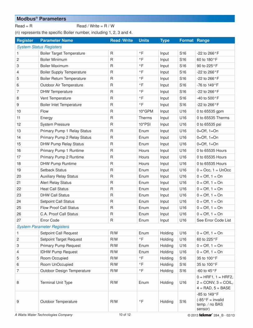
Register Parameter Name Read /Write Units Type Format RangeSystem Status Registers1 Boiler Target Temperature R °F Input S16 -22 to 266°F
2 Boiler Minimum R °F Input S16 60 to 180°F
3 Boiler Maximum R °F Input S16 90 to 225°F
4 Boiler Supply Temperature R °F Input S16 -22 to 266°F
5 Boiler Return Temperature R °F Input S16 -22 to 266°F
6 Outdoor Air Temperature R °F Input S16 -76 to 149°F
7 DHW Temperature R °F Input S16 -22 to 266°F
8 Vent Temperature R °F Input S16 -40 to 500°F
9 Boiler Inlet Temperature R °F Input S16 -22 to 266°F
10 Flow R 10*GPM Input U16 0 to 65535 gpm
11 Energy R Therms Input U16 0 to 65535 Therms
12 System Pressure R 10*PSI Input U16 0 to 65535 psi
13 Primary Pump 1 Relay Status R Enum Input U16 0=Off, 1=On
14 Primary Pump 2 Relay Status R Enum Input U16 0=Off, 1=On
15 DHW Pump Relay Status R Enum Input U16 0=Off, 1=On
16 Primary Pump 1 Runtime R Hours Input U16 0 to 65535 Hours
17 Primary Pump 2 Runtime R Hours Input U16 0 to 65535 Hours
18 DHW Pump Runtime R Hours Input U16 0 to 65535 Hours
19 Setback Status R Enum Input U16 0 = Occ, 1 = UnOcc
20 Auxiliary Relay Status R Enum Input U16 0 = Off, 1 = On
21 Alert Relay Status R Enum Input U16 0 = Off, 1 = On
22 Heat Call Status R Enum Input U16 0 = Off, 1 = On
23 DHW Call Status R Enum Input U16 0 = Off, 1 = On
24 Setpoint Call Status R Enum Input U16 0 = Off, 1 = On
25 Flow Proof Call Status R Enum Input U16 0 = Off, 1 = On
26 C.A. Proof Call Status R Enum Input U16 0 = Off, 1 = On
27 Error Code R Enum Input U16 See Error Code List
System Parameter Registers1 Setpoint Call Request R/W Enum Holding U16 0 = Off, 1 = On
2 Setpoint Target Request R/W °F Holding U16 60 to 225°F
3 Primary Pump Request R/W Enum Holding U16 0 = Off, 1 = On
4 IDHW Pump Request R/W Enum Holding U16 0 = Off, 1 = On
5 Room Occupied R/W °F Holding S16 35 to 100°F
6 Room UnOccupied R/W °F Holding S16 35 to 100°F
7 Outdoor Design Temperature R/W °F Holding S16 -60 to 45°F
8 Terminal Unit Type R/W Enum Holding U160 = HRF1, 1 = HRF2,2 = CONV, 3 = COIL,4 = RAD, 5 = BASE
9 Outdoor Temperature R/W °F Holding S16
-85 to 149°F(-85°F = invalid temp. / no BAS sensor)
Modbus® ParametersRead = R Read / Write = R / W
(n) represents the specific Boiler number, including 1, 2, 3 and 4.

© 2013 284_B - 02/1311 of 12A Watts Water Technologies Company
Register Parameter Name Read /Write Units Type Format RangeBoiler Status Registers10,11,12,13 Boiler (n) Enable/Disable R/W Enum Holding U16 0 = Enable, 1 = Disable
28,36,44,52 Boiler (n) Type R Enum Input U160 = MOD, 1 = 1STG,2 = 2STG, 3 = EMS1,4 = EMS2
29,37,45,53 Boiler (n) Condensing R Enum Input U16 0 = No, 1 = Yes
30,38,46,54 Boiler (n) Outlet Temperature R °F Input S16 -22 to 266°F
31,39,47,55 Boiler (n) Modulation Rate R % Input U16 0 to 100%
32,40,48,56 Boiler (n) Runtime R Hours Input U16 0 to 65535 Hours
33,41,49,57 Boiler (n) Cycles R Num Input U16 0 to 65535
34,42,50,58 Boiler (n) Pump Status R Enum Input U16 0 = Off, 1 = On
35,43,51,59 Boiler (n) Pump Runtime R Hours Input U16 0 to 65535
Product Information
60 Product Model R Num Input U16 284
61 Firmware Revision R Num Input U16 SVN revision
62 Application Version R Num Input U16 J number letter (A=1, B=2,...)
Modbus® Parameters
Modbus® Troubleshooting
If there is no communication, check the following:Check that the polarity on the Modbus® A & B terminals is correct.Check that Modbus® GND terminal is securely connected.Check that the Baud Rate on both devices are the same.
•
•
•
If the communication is intermittent, check the following:
Check that the communication cable is of the twisted pair type.Reliable communication depends on the cable length & Baud rate used. Long cable length may require a lower Baud Rate.
•
•
Read = R Read / Write = R / W
(n) represents the specific Boiler number, including 1, 2, 3 and 4.

Product design, software and literature are Copyright ©2013 by tekmar Control Systems Ltd., A Watts Water Technologies Company
12 of 12 All specifications are subject to change without notice. Printed in Canada. 284_B - 02/13.
tekmar Control Systems Ltd., A Watts Water Technologies Company. Head Offi ce: 5100 Silver Star Road, Vernon, B.C. Canada V1B 3K4, 250-545-7749, Fax. 250-545-0650 Web Site: www.tekmarControls.com
Code Description0 No Error
1 EEPROM Error
2 Boiler Supply Sensor Error
3 Boiler Return Sensor Error
4 DHW Sensor Error
5 Outdoor Sensor Error
6 Vent Sensor Error
7 Boiler 1 Outlet Sensor Error
8 Boiler 2 Outlet Sensor Error
9 Boiler 3 Outlet Sensor Error
10 Boiler 4 Outlet Sensor Error
11 Boiler 1 Maximum Outlet Temperature Warning
12 Boiler 2 Maximum Outlet Temperature Warning
13 Boiler 3 Maximum Outlet Temperature Warning
14 Boiler 4 Maximum Outlet Temperature Warning
15 Boiler Inlet Sensor
Code Description16 Flow Proof Error
17 C.A. Proof Error
18 Vent Maximum Temperature Warning
19 No Heat Warning
20 tN4 Duplicate Master
21 tN4 Schedule Master
22 tN4 Schedule Member
23 tN4 Device Lost (Bus b)
24 tN4 Device Lost (Bus 1)
25 tN4 Device Lost (Bus 2)
26 tN4 Device Lost (Bus 3)
27 tN4 Device Error (Bus b)
28 tN4 Device Error (Bus 1)
29 tN4 Device Error (Bus 2)
30 tN4 Device Error (Bus 3)
Error Codes