barriers - iowa department of transportation barriers ba no. date title void concrete barriers...
TRANSCRIPT
Barriers
BA
T

SECTION
Barriers BANO. DATE TITLE
Void Concrete BarriersBA-100 04-20-10 44" Concrete Median Barrier (Full Section)BA-101 10-21-14 44" Concrete Median Barrier Width TransitionBA-102 10-21-14 44" Concrete Barrier (Half Section)BA-103 04-20-10 34" Concrete Barrier (Half Section)BA-104 04-20-10 34" Concrete Barrier for use with Reinforced Paved ShoulderBA-105 04-20-10 34" to 44" Concrete Barrier Transition SectionBA-106 10-21-14 Reinforced Paved Shoulder for Concrete BarrierBA-107 10-18-11 Concrete Barrier End SectionBA-108 10-17-17 Concrete Barrier Tapered End Section BA-150 04-19-11 Side Obstacle Protection with Concrete Barrier and Guardrail
Void Steel Beam GuardrailBA-200 10-18-16 Steel Beam Guardrail ComponentsBA-201 04-18-17 Steel Beam Guardrail Barrier Transition Section (MASH TL-3)BA-202 10-20-15 Steel Beam Guardrail Bolted End AnchorBA-203 10-18-11 Steel Beam Guardrail W-Beam End AnchorBA-204 10-18-11 Steel Beam Guardrail Thrie-Beam End AnchorBA-205 04-19-16 Steel Beam Guardrail Tangent End Terminal (MASH TL-3)BA-206 10-18-16 Steel Beam Guardrail Flared End Terminal For Cable Connection (MASH TL-3)BA-210 04-19-16 Guardrail Post Adaptor UnitBA-211 10-21-14 Steel Beam Guardrail Long - Span System for Post Conflicts BA-221 04-18-17 Steel Beam Guardrail Barrier Transition Section (MASH TL-2)BA-225 10-17-17 Steel Beam Guardrail Tangent End Terminal (MASH TL-2)BA-250 10-18-16 Steel Beam Guardrail Installation at Concrete Barrier or Bridge End Post (MASH TL-3)BA-251 04-19-16 Steel Beam Guardrail Installation at Side Obstacle (Two-Way Protection)BA-252 04-19-16 Steel Beam Guardrail Installation at Side Obstacle (One-Way Protection)BA-253 04-19-16 Steel Beam Guardrail Installation at Railroad SignalBA-260 10-18-16 Steel Beam Guardrail Installation at Concrete Barrier or Bridge End Post (MASH TL-2)
10-17-17

SECTION
Barriers BANO. DATE TITLE
Void Cable GuardrailBA-351 04-20-10 High Tension Cable Guardrail
VoidVoid Temporary Barrier Rails
BA-400 04-16-13 Temporary Barrier Rail (Steel)BA-401 04-16-13 Temporary Barrier Rail (Precast Concrete)
Void Crash CushionsBA-500 04-19-16 Temporary Crash Cushions Sand Barrel
10-17-17
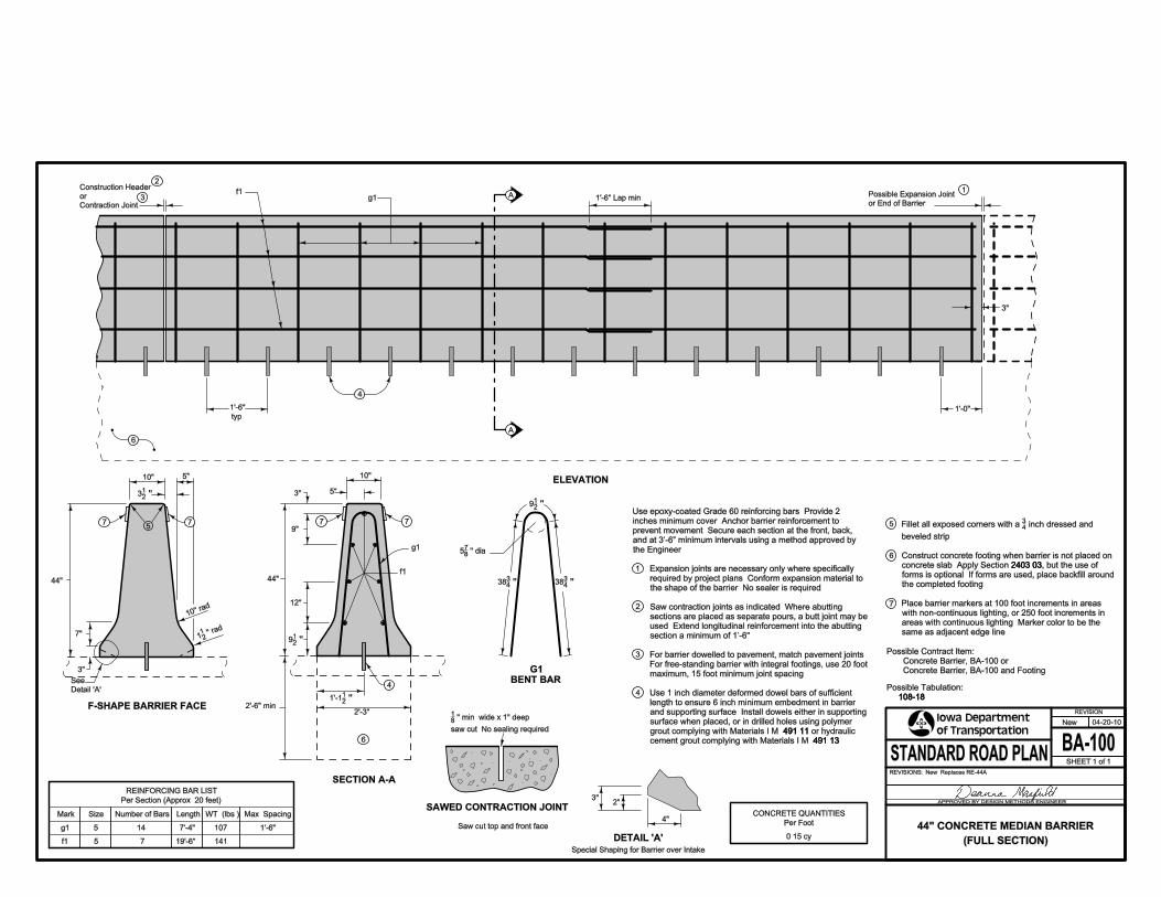
Possible Contract Item:
Concrete Barrier, BA-100 or
Concrete Barrier, BA-100 and Footing
4
3"
Per Foot
5"
SECTION A-A
g1
5"
9"
10"
12"
44"
WT. (lbs.) CONCRETE QUANTITIES
1415
Size Number of Bars
7’-4"
19’-6"0.15 cy
7"
See
Detail ’A’
7 7
Max. Spacing
F-SHAPE BARRIER FACE
6
1’-6"107
ELEVATION
Saw cut top and front face
7 75
f1
2’-3"
4"
5
Af1
3
4
1
2
3"
A
g1
1’-0"
6
Special Shaping for Barrier over Intake
REINFORCING BAR LIST
Length
DETAIL ’A’
2"3"Per Section (Approx. 20 feet)
g1
f1
Mark
14
7
Possible Expansion Joint
or End of Barrier
3"
1’-6"
typ.
44"
10"
G1
BENT BAR
1’-6" Lap min.
10’’ ra
d.
578 ’’ dia.
2’-6" min.
112 ’’ r
ad.
3834 ’’ 38
34 ’’
912 ’’
18 ’’ min. wide x 1" deep
saw cut. No sealing required.
1’-112 ’’
912 ’’
312 ’’
1
2
3
5
6
7
4Possible Tabulation:
108-18
491.11
491.13
108-18
Fillet all exposed corners with a 34 inch dressed and
beveled strip.
Construct concrete footing when barrier is not placed on
concrete slab. Apply Section 2403.03, but the use of
forms is optional. If forms are used, place backfill around
the completed footing.
Place barrier markers at 100 foot increments in areas
with non-continuous lighting, or 250 foot increments in
areas with continuous lighting. Marker color to be the
same as adjacent edge line.
2403.03
SAWED CONTRACTION JOINT
Expansion joints are necessary only where specifically
required by project plans. Conform expansion material to
the shape of the barrier. No sealer is required.
Saw contraction joints as indicated. Where abutting
sections are placed as separate pours, a butt joint may be
used. Extend longitudinal reinforcement into the abutting
section a minimum of 1�-6’’.
For barrier dowelled to pavement, match pavement joints.
For free-standing barrier with integral footings, use 20 foot
maximum, 15 foot minimum joint spacing.
Use 1 inch diameter deformed dowel bars of sufficient
length to ensure 6 inch minimum embedment in barrier
and supporting surface. Install dowels either in supporting
surface when placed, or in drilled holes using polymer
grout complying with Materials I.M. 491.11 or hydraulic
cement grout complying with Materials I.M. 491.13.
Use epoxy-coated Grade 60 reinforcing bars. Provide 2
inches minimum cover. Anchor barrier reinforcement to
prevent movement. Secure each section at the front, back,
and at 3�-6� minimum intervals using a method approved by
the Engineer.
BA-100
REVISION
04-20-10
SHEET 1 of 1
REVISIONS:New. Replaces RE-44A.
APPROVED BY DESIGN METHODS ENGINEER
STANDARD ROAD PLAN
New
44" CONCRETE MEDIAN BARRIER
(FULL SECTION)
Construction Header
or
Contraction Joint

1
2
18"18"9"
16" 16"
18" 9"
1
g1
6'-0"
3" 3"
f1
1
g3 g4 g5
44"
9"
18" 16"
3"
12"
217"
34"
g5
44"
1
27"
D = pin diameter
All "g" Bars
BENT BARS
Possible BA-102
Possible BA-102
BA-100
Possible
10"
1
SECTION B-B
44"
27"
2
g3
SECTION C-C
34"
44"
2
1
44"
27"
1
1
1
6'-0"
5
5
5
34"
69"5
1g1
Size
REINFORCING BAR LIST
LengthMark Number of Bars
g3
g4
g5
7f1
g2
A
A
PLAN
8
Weight (lbs.)
ISOMETRIC
6'-0"
C
g1 g2
B
BC
87"
89"
91"
5
5
Per Section (6'-0")
94"
8
8
892"
42
8
ELEVATION
SECTION A-A
''21
30
''21
13
''21
9
''87
D = 5
491.11
491.13
3
3
3
3
491.13
491.11
sections.
Provide 18 inch overlap of reinforcing steel between
beveled strip.
inch dressed and 43
Fillet all exposed corners with a
.cement grout complying with Materials I.M.
or hydraulic grout complying with Materials I.M.
surface when placed or in drilled holes using polymer
and supporting surface. Install bars either in supporting
length to ensure 6 inch minimum embedment in barrier
Use 1 inch diameter deformed dowel bars of sufficient
the Engineer.
and at 3'-6" minimum intervals using a method approved by
prevent movement. Secure each section at the front, back,
inches minimum cover. Anchor barrier reinforcement to
Use epoxy-coated grade 60 reinforcing bars. Provide 2
108-18
CONCRETE QUANTITIES
1.3 cy
BA-101
REVISION
10-21-14
SHEET 1 of 1
REVISIONS:Added CONCRETE QUANTITIES Per Section.
APPROVED BY DESIGN METHODS ENGINEER
STANDARD ROAD PLAN
1
WIDTH TRANSITION
44" CONCRETE MEDIAN BARRIERPer Section
108-18
Possible Tabulation:
Concrete Barrier, BA-101
Possible Contract Item:

1
2
3
4
5
6
7
Length
14
7
6
2"
REINFORCING BAR LIST
Per Section (Approx. 20 feet)
5
Size Number of Bars
g1
f1
5
g1
6
6
4
f1
ELEVATION
34"
7
5
typ.
7'-3"
or End of Barrier
Possible Expansion Joint
BARRIER FACE
1'-6" Lap. min.
Bar Weight (lbs.) CONCRETE QUANTITIES
19'-6"
Per foot
0.11 cy
1
Detail 'A'
See
A
A
3"
3"
f1
9"
1'-6"
g1
30" min.
5"
3"
7"
SECTION A-A
44"
1'-0"
4
DETAIL 'A'
2"
17"
11"
3"
SAWED CONTRACTION JOINTSpecial Shaping for Barrier over Intake
4"
Saw cut top and front face. Saw cut back if exposed.
BENT BAR
g1
20" dia.
''85
6
'' dia.85
3
''83
39
''85
30
''83
5''
87
4
''21
8
''21
4
''21
11
''21
9
''21
8
saw cut. No sealing required.
" min. wide x 1" deep81
10" ra
d.
'' rad.
211
''21
8
''21
3 3’-6” intervals using a method approved by the Engineer.movement. Secure each section at the front, back, and at
inches minimum cover. Anchor all reinforcement to prevent
Use Grade 60 epoxy-coated reinforcing bars. Provide 2
491.11
491.13
Spacing
1'-6"
___
3
2
2403.032403.03
same as adjacent edge line.
areas with continuous lighting. Marker color to be the
with non-continuous lighting, or 250 foot increments in
Place barrier markers at 100 foot increments in areas
the completed footing.
forms is optional. If forms are used, place backfill around
, but the use of concrete slab. Apply Section
Construct concrete footing when barrier is not placed on
beveled strip.
dressed and inch 43
Fillet all exposed corners with a
491.13
491.11
.cement grout complying with Materials I.M.
or hydraulic grout complying with Materials I.M.
surface when placed, or in drilled holes using polymer
and supporting surface. Install dowels either in supporting
length to ensure 6 inch minimum embedment in barrier
Use 1 inch diameter deformed dowel bars of sufficient
maximum, 15 foot minimum joint spacing.
For free-standing barrier with integral footings, use 20 foot
For barrier dowelled to pavement, match pavement joints.
into the abutting section a minimum of 1’-6''. butt joint may be used. Extend longitudinal reinforcement
Where abutting sections are placed as separate pours, a
the shape of the barrier. No sealer is required.
required by project plans. Conform expansion material to
Expansion joints are necessary only where specifically
Contraction Joint
or
Construction Header
106
141
BA-102
REVISION
10-21-14
SHEET 1 of 1
REVISIONS:Changed Possible Tabulation.
APPROVED BY DESIGN METHODS ENGINEER
STANDARD ROAD PLAN
2
(HALF SECTION)
44" CONCRETE BARRIER
108-18
Possible Tabulation:
Concrete Barrier, BA-102 and Footing
Concrete Barrier, BA-102 or
Possible Contract Item:
108-18

BA-103
REVISION
04-20-10
SHEET 1 of 1
REVISIONS:New. Replaces RE-44E.
APPROVED BY DESIGN METHODS ENGINEER
STANDARD ROAD PLAN
New
34" CONCRETE BARRIER
(HALF SECTION)
1
2
3
4
5
6
7
8
A
A
6
4
SAWED CONTRACTION JOINT
4"
17"
BA-103
Saw cut top and front face. Saw cut back if exposed.
5"
4
g1
f1
7
7
8
g1
BENT BAR
BARRIER FACE
1’-6" Lap min.
See
Detail ’A’
1Possible Expansion Joint
or End of Barrier
5
5
3"
Special Shaping for Barrier over Intake
DETAIL ’A’
2"
10"
3"
SECTION A-A
3"
ELEVATION
3"
30" min.
24"
Per foot
1’-0"
34"
2"
f16’ region of bar transition when
attaching to BA-105 or BA-107
g1
CONCRETE QUANTITIES
0.10 cy
7" 7"
20" dia.
312’’ dia.
18’’ min. wide x 1" deep
saw cut. No sealing required.
578’’
2078’’
414’’
3018’’
912’’
434’’
1112’’
912’’
812’’
112’’ ra
d.
10" ra
d.
912’’
212’’
Possible
BA-105 or BA-107
1’-6" typ.
Length
14
5
REINFORCING BAR LIST
Per Section (Approx. 20 feet)
5
Size Number of Bars
g1
f1
5 5’-8"
Bar Weight (lbs.)
19’-6"
83
98
Use Grade 60 epoxy-coated reinforcing bars. Provide 2
inches minimum cover. Anchor all reinforcement to prevent
movement. Secure each section at the front, back, and at
3�-6� intervals using a method approved by the Engineer.
108-18B
491.11
491.13
BA-103
BA-105 BA-107
1’-6"
Spacing
___
3
2
Possible Contract Item:
Concrete Barrier, BA-103 or
Concrete Barrier, BA-103 and Footing
Possible Tabulation:
108-18B
Fillet all exposed corners with a 34 inch dressed and
beveled strip.
Construct concrete footing when barrier is not placed on
concrete slab. Apply Section 2403.03, but the use of
forms is optional. If forms are used, place backfill around
the completed footing.
Place barrier markers at 100 foot increments in areas
with non-continuous lighting, or 250 foot increments in
areas with continuous lighting. Marker color to be the
same as adjacent edge line.
2403.03Expansion joints are necessary only where specifically
required by project plans. Conform expansion material to the
shape of the barrier. No sealer is required.
Where abutting sections are placed as separate pours, a butt
joint may be used. Extend longitudinal reinforcement into the
abutting section a minimum of 1�-6’’.
For barrier dowelled to pavement, match pavement joints.
For free-standing barrier with integral footings, use 20 foot
maximum, 15 foot minimum joint spacing.
When connecting to BA-105 or BA-107, include 4 additional
#5 bars embedded a minimum of 3 feet into the BA-103
barrier.
Use 1 inch diameter deformed dowel bars of sufficient length
to ensure 6 inch minimum embedment in barrier and
supporting surface. Install dowels either in supporting
surface when placed, or in drilled holes using polymer grout
complying with Materials I.M. 491.11 or hydraulic cement
grout complying with Materials I.M. 491.13.
Construction Header
or
Contraction Joint

BA-104
REVISION
04-20-10
SHEET 1 of 1
REVISIONS:New. Replaces RE-44F.
APPROVED BY DESIGN METHODS ENGINEER
STANDARD ROAD PLAN
New
34" CONCRETE BARRIER
FOR USE WITH
REINFORCED PAVED SHOULDER
1
2
3
4
5
4"
A
A
3
5Reinforced
Paved Shoulder
Reinforced
Paved Shoulder
5
5g2
Possible Expansion Joint
or End of Barrier
BARRIER FACE
5g1
BENT BAR
Saw cut top and front face. Saw cut back if exposed.
SAWED CONTRACTION JOINT
7’’
ELEVATION
D=4’’
BA-107
19’-4’’6f1
Bar
5g1
Per Section (Approximately 20’)
Reinforcing Steel - Lbs.
Concrete - Cu. Yds.
15
9
Length
5’’
7’’
5g1 6f1
Per Linear Foot
REINFORCING BAR LIST
ESTIMATED QUANTITIES FOR BARRIER
0.12
17.5
PossibleBA-104
1
7"
4"
17’’
2
34’’
5"
SECTION A-A
8’’
3’’
6f1
7"
3"
2’’
Number of Bars
5’-812’’
18" min. wide x 1" deep saw cut.
No sealing required.
10’’ rad.
112’’ rad.
912’’
412’’
712’’
5g1
4
6f1
5g3
2’-512’’
2’-212’’
1’-1014’’
D=434’’
4 34 ’’
814’’
Use Grade 60 epoxy-coated reinforcing bars. Provide 2
inches minimum cover. Anchor all reinforcement to prevent
movement. Secure each section at the front, back, and at
3�-6� intervals using a method approved by the Engineer.
Expansion joints are necessary only where specifically
required by project plans. Conform expansion material to
the shape of the barrier. No sealer is required.
Where abutting sections are placed as separate pours, a
butt joint may be used. Extend longitudinal reinforcement
into the abutting section a minimum of 1�-6�. Contraction
joint locations shall match pavement joint locations.
Fillet all exposed corners with a 34 inch dressed and
beveled strip.
Place barrier markers at 100 foot increments in areas
with non-continuous lighting, or 250 foot increments in
areas with continuous lighting. Marker color to be the
same as adjacent edge line.
Refer to BA-106 for details of 5g2 bars, 5g3 bars, and
reinforced paved shoulder.
108-18B
BA-106
Construction Header
or Contraction Joint
Spacing
1’-4’’
___
Possible Contract Item:
Concrete Barrier, BA-104
Possible Tabulation:
108-18B

BA-105
REVISION
04-20-10
SHEET 1 of 1
REVISIONS:New. Replaces RE-44G.
APPROVED BY DESIGN METHODS ENGINEER
STANDARD ROAD PLAN
New
34" TO 44" CONCRETE BARRIER
TRANSITION SECTION
1
2
3
4
5
7’’
5’’
7’’
for one Transition Section
SAWED CONTRACTION JOINT
3’’ 1’-4"1’-4"
1’-0’’ 1’-4"
f2
g1f1 3’’
f1
7
3’’
f2
1’-4"
1Contraction
Joint
1
2
4
Contraction
Joint
3
2
5
5"
17"
3
Weight (lbs.)
1’-5"
BA-105 Transition Section (10’-0")
1’-4"1’-4" 1’-5"
or BA-107
Bar
BA-102Possible BA-103
7"
3"
REINFORCING BAR LIST
Length
g1
20" dia.
30" min.
2"
ELEVATION
1’-0’’
Saw cut top and front face. Saw cut back if exposed.
g1
TYPICAL SECTION
f2
4f1
53.5
73.5
11.8
11’’
9’’3’’
5’-8"
Number of Bars
CONCRETE QUANTITIES
for one Transition Section
5
5
Size
2
*
10’-0"
1.2 cy5
8
g1
BENT BAR
* Varies from 5’-7" to 7’-3"
1112’’
912’’
712’’
412’’
18’’ min. wide x 1" deep
saw cut. No sealing required.
812"
Varies from
34" to 44"
Varies from
812’’ to 9
12’’
434’’
Varies from
212’’ to 3
12’’
10" rad.
112’’ rad.
Varies from
2938’’ to 39
38’’
358’’ dia.
658’’
Varies from
2058’’ to 30
58’’
478’’5
38’’
1’-4" 1’-4" 1’-4" 1’-4" 1’-4"
Use Grade 60 epoxy-coated reinforcing bars. Provide 2
inches minimum cover. Anchor all reinforcement to prevent
movement. Secure each section at the front, back, and at
3�-6� intervals using a method approved by the Engineer.
108-18B
491.11
491.13
Possible Contract Item:
Concrete Barrier, BA-105 or
Concrete Barrier, BA-105 and Footing
Possible Tabulation:
108-18B
Where abutting sections are placed as separate pours,
a butt joint may be used. Extend longitudinal
reinforcement into the abutting section a minimum of
1�-6�.
Use 1 inch diameter deformed dowel bars of sufficient
length to ensure 6 inch minimum embedment in barrier
and supporting surface. Install dowels either in
supporting surface when placed, or in drilled holes using
polymer grout complying with Materials I.M. 491.11 or
hydraulic cement grout complying with Materials I.M.
491.13.
Fillet all exposed corners with a 34 inch dressed and
beveled strip.
Construct concrete footing when barrier is not placed on
concrete slab. Apply Section 2403.03, but the use of
forms is optional. If forms are used, place backfill around
the completed footing.
Place barrier markers at 100 foot increments in areas
with non-continuous lighting, or 250 foot increments in
areas with continuous lighting. Marker color to be the
same as adjacent edge line.
2403.03

1
2
L2
BEVELED KEY
5'-1''
ESTIMATED SHOULDER QUANTITIES Per Linear Foot
4'
4
6e1 18
TYPICAL SECTION
12
18
Beveled Key
2
6e1
5e2
Pavement
Roadway
L2
1
5
17''2''
5e3
5g2
5g3
Face of Barrier
4''
4''
Face of Barrier
3
3
3''
5g2 6e1
2'-0''
5e2
5g3
5e3
2'' cover
2''
13''
L2
Paved Shoulder
5e2 bars spaced at 12''
Beveled Key
PLAN
2'' cover
2'' cover
Barrier
Concrete
8'6' 10' 12'4'
1'-0''
D
D
5g2 5g3
3''
Match roadway pavement
7''
Concrete
Sq. Yds.0.840.62 1.06 1.29 1.51
1
5''
18''
BENT BAR DETAILS
D=4''
17''
D
D=4''
D
5''
thickness (9'' min.)
''21
3'-2
''21
Length = 5'-1 ''41
Length = 3'-8
''43
6
''41
8
''21
1
''41
7
''41
4
'' cover21
2
1
4
4
5''
5e2
6e1
5e2
6e1
5e2
6e1
5e3
5g2
5g3 3
3 varies
varies varies
varies 5
5Widths
all Shoulder
Applies to
12'
10'18'-0''
13'-1''
18'-0''
18'-8''
12''
12''
12''
12''11'-1''18
8'
6'5e2
6e1
10
8
18
6
18
45e2 18'-0''
7'-1''
18'-0''
9'-1''
18'-0''
See Drawing
12''
12''
12''
12''
12''
12''
SpacingLengthof Bars
NumberBar
REINFORCING BAR LIST
Per Shoulder Panel (Approximately 20 Linear Feet)
L2
3
4
PV-101
PV-101
BA-107
Place keys at 2'-8'' centers.
Use 2 x 8 lumber 8'' long to make keys.
108-18B
Possible Tabulation:
Reinforced Paved Shoulder for Concrete Barrier
Possible Contract Item:
BA-107
PV-101
PV-101
Match spacing of vertical bars in concrete barrier.
paved shoulder thickness greater than 9 inches.
Increase these dimensions by one inch for every inch of
.reinforcement as shown on
end section, replace 5g2 and 5g3 bars with
When shoulder will be located under a concrete barrier
shoulder.
No 'CD' joint baskets required within 4' of outside edge of
. 'CD' joint. Match roadway joint locations. See
. use 'BT-3' joint. See
'L-2' or 'KT-2' joint. When roadway pavement is existing,
BA-106
REVISION
10-21-14
SHEET 1 of 1
REVISIONS:Changed Possible Contract Item.
APPROVED BY DESIGN METHODS ENGINEER
STANDARD ROAD PLAN
4
FOR CONCRETE BARRIER
REINFORCED PAVED SHOULDER
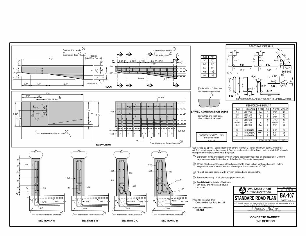
1
3
4
5
2’-0"1’-0" 4’-0"
5"5d2
Gutter Line
2" 17"
A
A
B
D
D
C
4 @ 9" = 3’-0"
17"
PLAN
BENT BAR DETAILS
2
3"
7’-0"
5d1
5c4
5d3
2 @ 9"2 @ 6"
C
SECTION D-D
5c16e1
5Reinforced Paved Shoulder
5d3
Reinforced Paved Shoulder5
Reinforced Paved Shoulder5
3
5Reinforced Paved Shoulder
3
5c1
3
5c2 5c1
3
3"
6e15c10
5e3
5c10
5e3
5d1
5e3
7"
5d2
B
7"
5e3
5"
5c5
SECTION B-BSECTION A-A
5d2
SECTION C-C
6e16e1
5c3
5d1
5c9
5c3
5c3
5d3
2"
ALL DIMENSIONS ARE OUT TO OUT. D = PIN DIAMETER.
1’-0"
2’-6"
CONCRETE QUANTITIES
VERTICAL
Per End Section
0.62 cy
2’-6"
4"
11"
VERTICAL 2
8
VERTICAL
10
42
VERTICAL
518
5c4 124
D=4"
5c25c1
D=4"
8"
D=4"
6"
5c3
5d2
5c4
1’-6"
3’-1"
1’-6"
3’-2"5c5-5c9
5’-10"
4"
7"
7"
2"
4"
3’-2"
1’-6"
5c10
"X"
5"
D=4"
5
SHAPE
HORIZONTAL
HORIZONTAL
NO. WEIGHT LENGTH
5d3
5d2
5d1
LOCATION
HORIZONTAL
VERTICAL
VERTICAL
VARIES
TOTAL WEIGHT (LBS.)
REINFORCING BAR LIST
35
4
5
28
5c5-5c9
Saw cut back if exposed.
Saw cut top and front face.
225
5c10 26
5
41
17
BAR
BAR
5c3
5c2
5c1
5c6
5c5
"X"
5c7
5c9
5c8
cut. No sealing required.
’’ min. wide x 1" deep saw81
SAWED CONTRACTION JOINT
6’-1’’
2’-10’’
6’-8 ’’
6’-9’’
3’-5’’
’’21
4’’
21
10
’’21
9
2"
BA-103 or BA-105
Possible
5c4
’’21
7
’’21
7
10" ra
d.
’’ rad.
211
"21
7
"21
4
108-18B
BA-106
Contraction Joint
or
Construction Header1
Contraction Joint
or
Construction Header1
2
2
’’21
2
"21
5
"41
D=4
"43
D=3
"21
D=4
"43
10
2"
Possible Tabulation:
Concrete Barrier Rail, BA-107
Possible Contract Item:
108-18B
5c5-5c9
Reinforced Paved Shoulder5
5Reinforced Paved Shoulder
4
5c2
2’-10"
3"
5c31’-8"
2’-0"
5c1
ELEVATION
7"
5c10
5c4
7’-0"
8"
2’-10"
1’-10"
1" dia. Holes
’’1613
3
’’1613
3
’’85
7
’’85
7
5c4
5’-0"
5’-0"
5’-0"
5d25d1
5d2
’’163
6
"43
D=3
’’81
10
’’1611
8
’’85
1’-1
’’81
1’-4
using a method approved by the Engineer.
reinforcement to prevent movement. Secure each section at the front, back, and at 3�-6� intervals
Use Grade 60 epoxy - coated reinforcing bars. Provide 2 inches minimum cover. Anchor all
BA-106
shoulder.
6e1 bars, and reinforced paved
for details of 5e3 bars, See
Form holes using 1 inch diameter plastic conduit.
inch dressed and beveled strip.43
Fillet all exposed corners with a
longitudinal reinforcement into the abutting section a minimum of 1�-6�.
Where abutting sections are placed as separate pours, a butt joint may be used. Extend
expansion material to the shape of the barrier. No sealer is required.
Expansion joints are necessary only where specifically required by project plans. Conform
5d1
BA-107
REVISION
10-18-11
SHEET 1 of 1
REVISIONS:Labeled 5d2 bars. Modified ’X’ bar dimensions and respective bar lengths
and bar weights. Updated language in notes.
APPROVED BY DESIGN METHODS ENGINEER
STANDARD ROAD PLAN
2
END SECTION
CONCRETE BARRIER

1
2
3
4
5
6
7''
17''
5''
SECTION C-C
'E' Joint
Extended Bridge Approach Pavement
2'-10''
2'-0''
3''
in barrier
Center dowel
3
4
1.061.26 0.87 0.540.701.48
4
16.0
2.13 1.701.91 0.00
Sidewalk
SLOPE
0.020.300.42 0.20 0.060.12
ISOMETRIC VIEW
Curb
SLOPE
6
12' Top Rounding
TRAFFIC
Barrier Section
SLOPE
PLAN
3
30'
5
10'
4'
10'
Curb10:1 Taper
TRAFFIC
Spaced 1'-3'' C-C
TRAFFIC
P
Bridge
Varies
3' min.
'BT-2' or 'KT-2'4
(On Bridge)
Sidewalk
SECTION A-A
Sidewalk
SECTION B-B
Possible Intake
2' Boxout
1Normal Pavement Jointing20'
'E' Joint 30' Concrete Approach Barrier
Sidewalk
SLOPE
SLOPE
4
2
Varies
SLOPE
Curb
2.0
6
1.0 4.03.0Y = Distance from P
ft.
Concrete Approach Barrier
3
12.011.0 13.0 15.014.010.06.05.0 7.0 9.08.0
4'E' Joint
Y
10'
16'
ELEVATION
C
Curb
6
3
6
ft.
Barrier Rail
Concrete Bridge
OFFSETS FOR ROUNDED BARRIER TOP
30' Concrete Approach Barrier
10'
Varies
X = Offset to Rounded Top
BA
A B C
X
'' rad.21
1
10'' rad.
'' bevel43
''21
9
120'
10'
Through Pavement
Normal Edge of
'BT-2', 'BT-3', or 'KT-2' 'BT-2', 'BT-3', or 'KT-2'
4
Through Pavement
Normal Edge of
Concrete Approach Barrier
10' Normal Concrete
FULL BARRIER RAIL SECTION
pavement.
location of each joint in both roadway and bridge approach
Install a 'C' joint in concrete approach barrier to match the
7
8
9
10
888
9 10
7
108-18B
Possible Tabulation:
Concrete Barrier, Tapered End, BA-108
Possible Contract Item:
108-18B
PV-101
INFODESIGNER
Pavement
Bridge Approach
Barrier Rail Coincide at This Point
Face of Approach Barrier and Bridge
Chain Link Fence
Handrail orindividual project requirements.
the Engineer to comply with
and dimensions determined by
Possible Sidewalk - exact shape
Barrier Rail
Concrete Bridge
Bridge End
Match Joint at
Pavement
Roadway
Roadway Pavement
Extended
Pavement
Roadway
Through Pavement
Normal Edge of
Roadway Pavement
Extended
Pavement
Bridge Approach
PV-101
depending on individual site requirements.
to construct barrier as shown. Amount may vary
Approximately 2.0 cubic yards of concrete are required
the barrier.
Place no delineator or object marker in front of, or on,
quantity.
roadway pavement will be included in roadway paving
Additional concrete quantity required for extended
separately.
Required sidewalk will be measured and paid for
Bottom width of barrier transitions from 8 to 17 inches.
Bottom width of barrier is maintained at 17 inches.
.For joint detail, see
#8 x 8 inch deformed bars or 1 inch diameter smooth.
constructed.
2 foot wide boxout where curb and gutter are not
Match boxout width to existing curb and gutter joint. Use
requirements as directed by the Engineer.
Typical joint spacing and location. Follow specific project Traveled Way
Edge of
BA-108
REVISION
10-17-17
SHEET 1 of 1
REVISIONS:Added Designer Info button. Modified PLAN view to move 'BT-2' or 'K-2'
joint on Bridge Approach Pavement.
APPROVED BY DESIGN METHODS ENGINEER
STANDARD ROAD PLAN
2
TAPERED END SECTION
CONCRETE BARRIER

1
2
3
4
5
2’’
17’’
1
A
3
A Side Obstacle
Roadway Pavement
5
1
4
Obstacle
Side
PCC Paved Shoulder
LEGEND
Reinforced PCC Paved Shoulder
L
one-way protection
ends here for
Concrete Barrier
TRAFFIC
ADJACENT2
Steel Beam GuardrailSteel Beam Guardrail
Side Obstacle
2
3TRAFFIC
Concrete Barrier
BA-102
End Section
BA-107
Transition Section
BA-105
L2
10’
min.
2’
10’
PLAN
ELEVATION
SECTION A-A
Roadway Pavement
Transition Section
BA-105
End Section
BA-107
112-9
BA-106
108-18B
Possible Tabulations:
Reinforced Paved Shoulder
PCC Paved Shoulder
Steel Beam Guardrail items
Concrete Barrier items
Possible Contract Items:
112-9
108-18B
L
10’’ Preferred minimum
BA-106
PV-101
BA-250
PV-101
.Refer to
Refer to project typicals.
.See
�C� Joint; match existing roadway joints when possible.
.Refer to
.existing, use �BT-3� joint. See
�L-2� or �KT-2� joint. When roadway pavement is
PV-101
BA-250
PV-101
BA-150
REVISION
04-19-11
SHEET 1 of 1
REVISIONS:Updated references to renamed standards.
APPROVED BY DESIGN METHODS ENGINEER
STANDARD ROAD PLAN
1
CONCRETE BARRIER AND GUARDRAIL
WITH
SIDE OBSTACLE PROTECTION

1
1
INFODESIGNER
1
W-BEAM INSTALLATION
ELEVATION
PLAN
Rail
6'' x 12'' Blockout (typ.)
Height
Mounting
31''
''21
3'-1''21
3'-1
Height
Mounting
31''
Rail Elements
LAPPING PROCEDURE
Steel Beam Guardrail
Possible Contract Item:
Ground Elevation
10:1 Slope (max.)
SECTION WITH CURBSECTION
16d Nail 16d Nail
Height
Mounting
31''
16d Nail (typ.)
documents
in contract
as shown
(max.)
10:1 Slope
Elevation
Ground
TRAFFIC
NEAREST
2
Rail Splice (typ.)
W-Beam Rail 6'-3''
Elevation
Ground
1
Rail
6'' x 12'' Blockout (typ.)6'-0" Steel Post (typ.)
place post(s) such that Bridge End Drains abut post(s).and Turf Reinforcement Mat) or remove rock as required to At Bridge End Drains, cut Scour Protection (Transition Mat
2
3
3
allowed.
Wood or composite only. Steel blockouts will not be
non-standard curbs.
6" maximum for 6" Standard or 6" Sloped curbs and for
'' spacing.21
at 3'-1
When specified by the contract documents, install posts
3
6'-0" Wood Post (optional)
BA-200
REVISION
10-18-16
SHEET 1 of 4
REVISIONS:Added holes on steel posts and corresponding blockouts.
APPROVED BY DESIGN METHODS ENGINEER
STANDARD ROAD PLAN
4
STEEL BEAM GUARDRAIL COMPONENTS

POSTS
3''
3"
6" 6"
6'-0'' 3''
3"
6'-0''
L = Bolt Length
6"
12"
19"
HARDWARE
T = Min. Thread Length
6'' x 8'' Wood Post
'' dia. Hole43
''85
7
''85
7
'' dia.85
''41
1
NUT
BOLT
''43
7''
W-BEAM BLOCKOUT THRIE-BEAM BLOCKOUT
6"
6"
W6x9 or W6x8.5
''83
''87
PLAN
ELEVATION ELEVATION
PLAN
''41
4
''83
12
''85
7
12''
BOLT DETAILS
Splice Bolt
22''
LTAPPLICATION
''41
1''161
1
''21
2 18''
''21
2 14''
''21
2
Bolt for Wood Post with 8" Blockout
Bolt for Wood Post with 12" Blockout
Bolt for Steel Post with 12" Blockout
10''''21
2Bolt for Steel Post with 8" Blockout6"
12"
32"
Mounting
Height
Elevation
Ground
STEEL POST AND BLOCKOUT DETAILS
WOOD POST AND BLOCKOUT DETAILS
W-BEAM THRIE-BEAM
Holes
'' dia.43
Holes
'' dia.43
6'' x 8'' Wood Post
'' dia. Hole43
THRIE-BEAM INSTALLATION
6'-0''
Threads recessed
L
T
PLAN
ELEVATION
PLAN
ELEVATION
W-BEAM BLOCKOUT THRIE-BEAM BLOCKOUT
ShoulderOval
3
3 3
3 3
allowed.
Wood or composite only. Steel blockouts will not be
6'-0" STEEL POST
6'-0''
7'' 7''
7''
14"
7''
''43
''43
Holes Typ
'' dia.43
BA-200
REVISION
10-18-16
SHEET 2 of 4
REVISIONS:Added holes on steel posts and corresponding blockouts.
APPROVED BY DESIGN METHODS ENGINEER
STANDARD ROAD PLAN
4
STEEL BEAM GUARDRAIL COMPONENTS
7''
14''
''43
1
Hole
'' dia.43
''85
719''
7''
Holes
'' dia.43

20"
ASYMMETRICAL TRANSITION SECTION
''75
''41
12
''41
6
''21
12 ''21
62
''21
87
''21
37''
81
6
10-gauge Section
''81
4
Splice Bolt Slots (typ.)Post Bolt Slot (typ.)
W-BEAM RAIL
required per slot
One splice bolt
SECTIONRAIL SPLICEELEVATION
'' (typ.)21
3'-1
Post Bolt Slot
12'-6" or 25'-0'' "41
6
SECTIONRAIL SPLICEELEVATION
THRIE-BEAM RAIL
"41
6
Splice Bolt Slots (typ.)Post Bolt Slot (typ.)
'' 21
3'-1
''21
12
''41
6
''41
3
''163
6
''85
7
''41
12
''81
6
''41
3 ''
21
12
''41
6
''21
'' dia. x 243
''81
'' dia. x 13229
''81
'' dia. x 13229 ''
21
'' dia. x 243
required per slot
One splice bolt
20''
Slots
Post Bolt
2''
2''
12'-6"
6'-3"
BA-200
REVISION
10-18-16
SHEET 3 of 4
REVISIONS:Added holes on steel posts and corresponding blockouts.
APPROVED BY DESIGN METHODS ENGINEER
STANDARD ROAD PLAN
4
STEEL BEAM GUARDRAIL COMPONENTS

PLAN - CASE A PLAN - CASE B
6
24"
Post Embedment
Case
A
B
4
POST INSTALLED IN BEDROCK
Elevation
Ground
S
R Special Backfill
Drilled Hole
Top of Bedrock
12"
Drilled HoleDrilled Hole(s)
2" min. typ.
HeightMounting
Steel or Wood PostBlockout
Depth to Bedrock
S = 0" to 16"
S = 16" to 52"
R = 24"
R = Post Length - Mounting Height - S
Minimum Depth to Drill into Bedrock
3
POST INSTALLED IN PAVEMENT
5
5
6
Either approach is acceptable.
PLAN - PAVEMENT THICKNESS <= 8"
PLAN - PAVEMENT THICKNESS > 8"
Drilled Hole or Leave-out
Special Backfill
15" min.
7" min.
2" min. typ.
or Leave-out
Drilled Holes
15" min.
7" min.
or Leave-out
Drilled Hole
24"
2" min. typ.
Drilled Hole(s)
HeightMounting
Steel or Wood PostBlockout
3
4161
3
4
5
Installation information applies to both wood and steel posts.
6
4161
drill.
Use a 12 inch bit with three drills or a 24 inch bit with one
required area. Leave-out may be round or square.
leave-out area. If placing post after paving, drill or cut
drill. If placing post before paving, provide required
Use a 12 inch bit with two drills or a 15 inch bit with one
of the Standard Specifications.Section
post as required and treat with preservative according to
Post extends to bottom of hole in all cases. Trim top of
allowed.
Wood or composite only. Steel blockouts will not be
BA-200
REVISION
10-18-16
SHEET 4 of 4
REVISIONS:Added holes on steel posts and corresponding blockouts.
APPROVED BY DESIGN METHODS ENGINEER
STANDARD ROAD PLAN
4
STEEL BEAM GUARDRAIL COMPONENTS
Pavement Elevation
Ground

INFODESIGNER
ELEVATION
Height
Mounting
31"
Height
Mounting
32"
3
2
1
2
3
11
PLAN
3
Elevation
Ground
"21
" = 15'-743
10 spaces @ 1'-6
BA-202.
6'-3" Thrie-BeamTransition Section
6'-3" Asymmetrical 12'-6" Nested W-Beam12'-6" Nested Thrie-Beam
#1
Post
BTS
#2
Post
BTS
#3
Post
BTS
#4
Post
BTS
#5
Post
BTS
#6
Post
BTS
#7
Post
BTS
#8
Post
BTS
#9
Post
BTS
#10
Post
BTS
#11
Post
BTS
#12
Post
BTS
#13
Post
BTS
#14
Post
BTS
#15
Post
BTS
BA-202.eliminated or modified. See
Depending on end anchor type, BTS Post #15 may be
Possible 4 inch sloped curb. See project plans.
inches at BTS Post #3.
inches. Transition guardrail mounting height down to 31
Guardrail mounting height at barrier connection is 32
Barrier Transition Section (BTS) 37'-6"
" = 12-6"21
4 spaces @ 3'-1 6'-3"
6'-9" Steel Posts
7'-0" Wood Posts or6'-0" Wood or Steel Posts
LAPPING PROCEDURES
TRAFFIC
NEAREST
TRAFFIC
NEAREST
Rail Elements
Rail Elements
place post(s) such that Bridge End Drains abut post(s).
and Turf Reinforcement Mat) or remove rock as required to
At Bridge End Drains, cut Scour Protection (Transition Mat
2 2
BA-200 BA-200
shown
for one of the 12'-6" sections and the 6'-3" section as
* One 18'-9" Thrie-Beam rail section may be substituted
for guardrail components Refer to
Approved bolts, nuts, and washers
(2) 12'-6" W-Beam rail sections
(1) 6'-3" Thrie-Beam rail section*
(2) 12'-6" Thrie-Beam rail sections*
(1) Asymmetrical Transition Section
(3) 6" x 12" x 14" blockouts
(12) 6" x 12" x 19" blockouts
(6) 6" x 8" x 7'-0" posts
(9) 6" x 8" x 6'-0" posts
Wood Post Option:
(3) 6" x 12" x 14" blockouts
(12) 6" x 12" x 19" blockouts
(6) 6" x 8" x 6'-9" posts
(9) 6" x 8" x 6'-0" posts
Steel Post Option:
Materials included in the Contract Item:
Steel Beam Guardrail Barrier Transition Section, BA-201
Possible Contract Item:
BA-201
REVISION
04-18-17
SHEET 1 of 3
REVISIONS:POST #4 view on page 3. Added Circle Note 6 on Page 3.Changed Circle Note 5. Changed hole spacing dimensions on WOOD BTS
APPROVED BY DESIGN METHODS ENGINEER
STANDARD ROAD PLAN
5
(MASH TL-3)
BARRIER TRANSITION SECTION
STEEL BEAM GUARDRAIL

2
Height
Mounting
31"1
Section or Shoulder
Bridge Approach
2
Height
Mounting
31"1
Section or Shoulder
Bridge Approach
2
1
Section or Shoulder
Bridge Approach
2
1
Section or Shoulder
Bridge Approach
"21
31
Height
Mounting
Height
Mounting
32"
STEEL BTS POSTS #10-15
STEEL BTS POST #1-3 STEEL BTS POST #4
1
2
3
BA-202.
3
7''
14''
''43
1
Hole
'' dia.43
W6x9 or W6x8.5
6'-9''
7''
W6x9 or W6x8.5
''85
7
Holes
'' dia.43
6'-0''
(max.)
10:1 Slope
Elevation
Ground
(max.)
10:1 Slope
Elevation
Ground
(max.)
10:1 Slope
Elevation
Ground
(max.)
10:1 Slope
Elevation
Ground
POST
POST
''83
''87
''41
4
''83
12
6"
4
BLOCKOUT INSTALLATION
7''
''85
7
Holes
'' dia.43
6'-0''
W6x9 or W6x8.5
POST
7''
''85
7
Holes
'' dia.43
6'-0''
W6x9 or W6x8.5
POST
Plan
Elevation
19''''
85
7
7''
''43
1
Holes
'' dia.43
Plan
6"
12"
Plan
6"
12"
Plan
6"
12"
Elevation
19''''
85
7
7''
''43
1
Holes
'' dia.43
Elevation
19''''
85
7
7''
''43
1
Holes
'' dia.43
BLOCKOUT INSTALLATION BLOCKOUT INSTALLATION
BLOCKOUT INSTALLATION
Elevation
STEEL BTS POSTS# 5-9
7''
''85
7
Holes
'' dia.43
''43
''43
''43
''43
''43
''43
''43
''43
4 4
44
BA-202
Place bolt in top hole only.
allowed.
Wood or composite only. Steel blockouts will not be
.eliminated or modified. See
Depending on end anchor type, BTS Post #15 may be
Possible 4 inch sloped curb. See project plans.
inches at BTS Post #3.
inches. Transition guardrail mounting height down to 31
Guardrail mounting height at barrier connection is 32
5
5
BA-201
REVISION
04-18-17
SHEET 2 of 3
REVISIONS:POST #4 view on page 3. Added Circle Note 6 on Page 3.Changed Circle Note 5. Changed hole spacing dimensions on WOOD BTS
APPROVED BY DESIGN METHODS ENGINEER
STANDARD ROAD PLAN
5
(MASH TL-3)
BARRIER TRANSITION SECTION
STEEL BEAM GUARDRAIL

POST
POST BLOCKOUT
BLOCKOUT
Wood Post
6'' x 8''
3"
Wood Post
6'' x 8''
POST BLOCKOUT
INSTALLATION
BLOCKOUT INSTALLATION
Wood Post
6'' x 8''
Wood Post
6'' x 8''
POST
7'-0''
Plan
Elevation
Elevation
31"
Mounting
Height
INSTALLATION
32"
Mounting
Height
31"
Mounting
Height
INSTALLATION
6'-0''
Mounting
Height
3"
6'-0''
3"
11
1 1"
21
31
"85
7 "85
7
WOOD BTS POSTS #1-3 WOOD BTS POST #4
WOOD BTS POSTS #5-9 WOOD BTS POSTS #10-15
1
2
3
BA-202.
3
2
Section or Shoulder
Bridge Approach
2
2 2
(max.)
10:1 Slope
Elevation
Ground" dia. Holes
43
Section or Shoulder
Bridge Approach
Section or Shoulder
Bridge Approach
Section or Shoulder
Bridge Approach
(max.)
10:1 Slope
Elevation
Ground
(max.)
10:1 Slope
Elevation
Ground
(max.)
10:1 Slope
Elevation
Ground
4
63"
6"
12"
Plan
6"
12"
Plan
6"
12"
Plan
6"
12"
3"
19"
" dia. Holes43
Elevation
3"
"85
719"
Elevation
3"
"85
719"
" dia. Holes43
5
4 4
4
4
7"7"
14"
7"7"
7"7"
7"7"
3"
6'-0''
" dia. Holes43
"85
7"
85
7
BA-202
16d nail to prevent blockout rotation.
Place bolt in top hole only.
allowed.
Wood or composite only. Steel blockouts will not be
.eliminated or modified. See
Depending on end anchor type, BTS Post #15 may be
Possible 4 inch sloped curb. See project plans.
inches at BTS Post #3.
inches. Transition guardrail mounting height down to 31
Guardrail mounting height at barrier connection is 32
6
5
BA-201
REVISION
04-18-17
SHEET 3 of 3
REVISIONS:POST #4 view on page 3. Added Circle Note 6 on Page 3.Changed Circle Note 5. Changed hole spacing dimensions on WOOD BTS
APPROVED BY DESIGN METHODS ENGINEER
STANDARD ROAD PLAN
5
(MASH TL-3)
BARRIER TRANSITION SECTION
STEEL BEAM GUARDRAIL

INFODESIGNER
Washers"1615
Approved
Hex Nuts"87
Approved
x sufficient length Hex Bolts"87
Approved
Thrie-Beam Terminal Connector
Materials included in the Contract Item:
Steel Beam Guardrail End Anchor, Bolted
Possible Contract Item:
3
1 BA-201
Thrie-Beam Terminal Connector
2" long 1'' Slotted Holes
Connector
Terminal
Thrie-Beam
32'' Mounting Height
BTS Post #15
1
1'' Hole (typ.)
A
(typ.)
1'' dia. Hole
A
PLAN
TYPE A
''21
31
''21
11
''43
12 ''43
18
30''
''83
3
''21
8 ''41
4 ''41
4
20''
'')163
(+/-
1'' dia. Holes (typ.)
''21
1'' x 2
''85
7
''85
7
''85
7
''83
2
''83
2
''163
6
''163
6
showing min.
2 threads
Bolt and Washer
'' dia. Hex87
''85
7
''1613
3
''1613
3
''1613
3
''1613
3
Thrie-Beam Terminal Connector
3
3
(5) - 1" dia. Holes
Installation Line
Neutral Axis
ELEVATION
ELEVATION
DETAIL 'A' DETAIL 'B'PLAN
SECTION A-ATERMINAL CONNECTOR
THRIE - BEAM
See Detail 'A'
See Detail 'B'
50°
32'' Mounting Height
and Washer
'' dia. Hex Nut87
Nested Thrie-Beam Guardrail
5 - BOLT PATTERN
Possible Curb
Possible Curb
BA-201
bridge.
thrie beam rails for attachments on the trailing end of a
Lap the Terminal Connector on the outside of the nested
.See
Beam Rails
Nested Thrie
8''
Post Bolt Slot
3''8''2''
3''
or Bridge Rail End Section
Concrete Barrier End Section
BA-202
REVISION
10-20-15
SHEET 1 of 3
REVISIONS:Changed BTS post numbers to match changes to BA-201.
APPROVED BY DESIGN METHODS ENGINEER
STANDARD ROAD PLAN
3
BOLTED END ANCHOR
STEEL BEAM GUARDRAIL

1 BA-201
B
BTS Post #14
B
1
32" Mounting Height
1
Skip BTS Post #15
(7) - 1" dia. Holes ''21
37
Thrie-Beam Terminal Connector
TYPE B
PLAN
ELEVATION
SECTION B-B
Nested Thrie-Beam Guardrail
1'' dia. Hole
"85
7
''43
128''
"1613
3
"1613
3
"1613
3
"1613
3
Thrie - Beam Terminal Connector
"43
12
See Detail 'A'
See Detail 'B'
32'' Mounting Height
7 - BOLT PATTERN
Possible Curb
Possible Curb
BA-201.See
Installation Line
Curb
BA-202
REVISION
10-20-15
SHEET 2 of 3
REVISIONS:Changed BTS post numbers to match changes to BA-201.
APPROVED BY DESIGN METHODS ENGINEER
STANDARD ROAD PLAN
3
BOLTED END ANCHOR
STEEL BEAM GUARDRAIL

4
1 BA-201
(7) - 1" dia. Holes
32" Mounting Height
C
C
Thrie-Beam Terminal Connector
BTS Post #14
1
1
Skip BTS Post #15
(by others)
1'' dia. Hole
6" long Guardrail Bolts
(2) Approximately
edge of Wedge Blockout.
protrude past outside
Bolt so bolt does not
Countersink Guardrail
"21
4
"43
18 "43
18
TYPE C
PLAN
ELEVATION
SECTION C-C
DETAIL 'C'
Nested Thrie Beam Guardrail
Wedge Blockout
"85
7
''43
128''
"1613
3
"1613
3
"1613
3
"1613
3
Thrie - Beam Terminal Connector
Height32" Mounting
See Detail 'C'
at BTS Post #15
Wedge Blockout 4
See Detail 'A'
See Detail 'B'
30°
7 - BOLT PATTERN
BA-201
boards are incidental to bolted end anchor.
endpost. A nominal 1 inch gap is acceptable. Spacer
produce a tight fit between the wedge blockout and
Use treated spacer boards (1 in. x 6 in. or 2 in. x 6 in.) to
.See
Possible Curb
Installation Line
8"
Section of Guardrail
6"
BA-202
REVISION
10-20-15
SHEET 3 of 3
REVISIONS:Changed BTS post numbers to match changes to BA-201.
APPROVED BY DESIGN METHODS ENGINEER
STANDARD ROAD PLAN
3
BOLTED END ANCHOR
STEEL BEAM GUARDRAIL
1

INFODESIGNER
INSTALLATION
Typical Section
1" dia. Hole
17"
46"
14"
3’’ min.
4"
3"
1"
PLAN
ELEVATION
16’’
ROUNDED W-BEAM END SECTIONBCT POST ASSEMBLY
8"
End Section
31" Mounting Height
W-Beam Rail
Pipe Sleeve
Ground
Elevation
TRAFFIC
1"
Foundation Tubes
6"
INSTALLATION
END SECTION W-BEAM RAIL
Rounded W-Beam End Section
ELEVATION
FOUNDATION TUBE POST
ELEVATION
PLAN
Ground Strut Assembly
Anchor Assembly
BCT Cable
W-Beam Rail
End Section
Nut, and Washers (typ.)
" Hex Bolt,21
" dia. x 787
’’ rad.41
6
30°
’’41
12
’’41
2’’21
8
(Varies)
’’21
7
Height
Mounting
31"
Elevation
Ground
"21
28 " dia. Hole21
2
"43
3
"21
7
" dia. Hole43
" dia. Hole87
"21
5
"87
23
"81
7
"43
2" dia. Hole43
"163
TS 8" x 6" x
" x 3" slots acceptable).3229
" slots (81
" x 13229
1
1
Plate
Bearing
4"
Post Bolt Slot (typ.)
12’-6"
Anchor Bracket Slots (typ.)
Splice Bolt Slots (typ.)
12"
4" 4"
"21
3’-1
"21
" dia. X 243
"81
" dia. X 13229
"81
" dia. X 13229
"21
3’-1"21
3’-1
614"
(typ.)
4’-1"
Anchor Bracket
Cable
Possible Contract Item:
Steel Beam Guardrail End Anchor, W-Beam
Materials included in the Contract Item:
(2) Foundation Tube Assemblies
(2) BCT Wood Posts
(1) Rounded W-Beam End Section
(1) Cable Anchor Bracket
(1) BCT Cable Anchor Assembly
(1) Ground Strut Assembly
(1) Pipe Sleeve
(1) Bearing Plate
(1) W-Beam Post (wood or steel - match
remainder of installation)
Approved bolts, nuts, and washers
BA-203
REVISION
10-18-11
SHEET 1 of 1
REVISIONS:Changed to three post design and added materials included in the Contract
Item.
APPROVED BY DESIGN METHODS ENGINEER
STANDARD ROAD PLAN
1
W-BEAM END ANCHOR
STEEL BEAM GUARDRAIL
Front Side Front Side
BCT Post Assemblies
6’ - 0"Ebedment
5’ - 10"
(1) 12’-6" End Section W-Beam Rail
W - Beam End Anchor (12’-6")
(1) W-Beam Blockout
2 Refer to BA-200.
1
2
and BlockoutW-Beam post

INFODESIGNER
8’’
17’’6’’
6’’
5’-0’’
1’’3’’
6’-3"6’-3"6’-3"
" dia. Hole87
Holes
" dia. 87
"163
8" x 6" x
TS
2’’
3’’ min.
Approx.24’’
24’’
9’’ 6’’ 9’’
18’’
9’’
min.4’-10’’
Soil Plate
TubeFoundation
Cable Assembly
Pipe Sleeve
BracketAnchor
BlockoutPost and
Thrie-Beam
(6’-3")Section
TransitionAsymmetrical
TRAFFIC
(12’-6")Thrie-Beam Rail
LineGround
PlateBearing
End SectionThrie-Beam
Rounded
" Plate41
30°
(Varies)
"21
7 "21
8 "41
2
"21
7
"163
7
"85
7
"21
3’-11
" 21
1’-3
SOIL PLATE
ELEVATION
PLAN
20’’
ROUNDED THRIE-BEAM END SECTION
BCT WOOD POSTFOUNDATION TUBE
Front SideFront Side
PLAN
ELEVATION
"21
5
"43
3"43
2
"163
15
" dia. Hole87
" Slotted Hole21
" x 287
" dia. Hole21
2
’’ rad.41
6
" dia. Holes87
1
2
3
3
1
2
3
SectionTransition
Asymmetrical
2
BA-200
Wood PostBCT
Thrie - Beam End Anchor (18’-9")
BA-200
or Type IV reflective sheeting.
shall meet the retroreflectivity requirements for Type III
which traffic is to pass the end anchor. Yellow stripes
down at an angle of 45 degrees toward the side on
approximately 3 inches in width and shall be sloped
and yellow striped adhesive sheeting. Stripes shall be
Cover entire face of end section with alternating black
.Refer to
" long.81
" x 13229
Slotted holes
of thrie beam.
replace Asymetrical Transition with 6’ - 3"
When attaching anchor to thrie beam,
2
BlockoutPost andW-Beam
Approved bolts, nuts, and washers
(1) Pipe Sleeve
(1) Foundation Tube Assembly with Soil Plate
(1) Cable Assembly
(1) Anchor Bracket Assembly
(1) Rounded Thrie-Beam End Section
(1) BCT Wood Post
(2) Thrie-Beam blockouts
(1) W-Beam blockout
of installation)
(1) W-Beam post (wood or steel - match remainder
of installation)
(2) Thrie-Beam posts (wood or steel - match remainder
(1) Asymmetrical Transition Section
(1) 12’-6" Thrie-Beam rail section
Materials included in the Contract Item:
Steel Beam Guardrail End Anchor, Thrie-Beam
Possible Contract Item:
BA-204
REVISION
10-18-11
SHEET 1 of 1
REVISIONS:Changed block out size from 19" to 22". Clarified notes. Modified materials
included in Contract Items.
APPROVED BY DESIGN METHODS ENGINEER
STANDARD ROAD PLAN
1
THRIE-BEAM END ANCHOR
STEEL BEAM GUARDRAIL

INFODESIGNER
2 BA-200
NEAREST TRAFFIC
ELEVATION
PLAN
LAPPING PROCEDURE
108-8A
108-8B
108-8C
108-8D
BA-205
REVISION
04-19-16
SHEET 1 of 1
REVISIONS:New layout, notes, and title to reflect MASH approved end terminal.
APPROVED BY DESIGN METHODS ENGINEER
STANDARD ROAD PLAN
2
(MASH TL-3)
TANGENT END TERMINAL
STEEL BEAM GUARDRAIL
Possible Tabulations:
Steel Beam Guardrail Tangent End Terminal, BA-205
Possible Contract Item:
108-8D
108-8C
108-8B
108-8A
1
Impact Head
1
Ground Line
ET = 47'-8"
and Blockout
W-beam Post2
BA-200.Refer to
sheeting.
requirements for Type III or Type IV reflective
- Yellow stripes meet the retroreflectivity
traffic is to pass the end terminal.
down at a 45 degree angle toward the side on which
- Stripes are approximately 3 inches wide and slope
following requirements:
and yellow striped adhesive sheeting meeting the
Cover entire face of impact head with alternating black
455.02
maintenance manual for the alternate design.
Engineer with three copies of the most current installation and
shown. When such a substitution is made, provide the
the end terminal may be substituted for the post design
the manufacturer and accepted by the FHWA for use within
Contracting Authority, alternate post designs developed by
Note: at the Contractor's option, and at no cost to the
manufacturer's recommendations.
specifications. Install end terminals according to the
Use materials meeting the respective manufacturer's
for a list of approved sources.Refer to Materials I.M.
4" max
Post 8Post 7
Post 6Post 5
Post 4Post 3
Post 2Post 1 Post 0
HeightMounting31"
"21
Steel Beam Guardrail Tangent End Terminal 50'-9
to end of rail22" offset

ET = 37'-6"
1
INFODESIGNER
2 BA-200
Post 10
455.02
108-8A
108-8B
108-8C
NEAREST TRAFFIC
LAPPING PROCEDURE
ELEVATION
PLAN
3
Post 1
Post 2Post 3
Post 4Post 5
Post 6Post 7
Post 8Post 9
Possible Tabulations:
Steel Beam Guardrail Flared End Terminal, BA-206
Possible Contract Item:
108-8C
108-8B
108-8A
455.02
and maintenance manual for the alternate design.
the Engineer with three copies of the most current installation
design shown. When such a substitution is made, provide
within the end terminal may be substituted for the post
by the manufacturer and accepted by the FHWA for use
the Contracting Authority, alternate post designs developed
Note: at the Contractor's option, and at no additional cost to
manufacturer's recommendations.
specifications. Install end terminals according to the
Use materials meeting the respective manufacturer's
for a list of approved sources.Refer to Materials I.M.
12"
Height of Impact Head
ADHESIVE SHEETING
Adhesive Sheeting
ADHESIVE SHEETING PLACEMENT
11
Buffered End SectionImpact Head or
to end of rail48" offset
4
BA-200
" section as shown.21
the 12'-6" section and the 3'-1
" W-beam rail section may be substituted for 21
One 15'-7
terminal.
" W-beam rail section is incidental to end 21
The 3'-1
.Refer to
sheeting.
requirements for Type III or Type IV reflective
-Yellow stripes meet the retroreflectivity
traffic is to pass the end terminal.
down at a 45 degree angle toward the side on which
-Stripes are approximately 3 inches wide and slope
meeting the following requirements:
alternating black and yellow striped adhesive sheeting
Cover face of impact head or buffered end section with
BA-206
REVISION
10-18-16
SHEET 1 of 1
REVISIONS:" dimension. Added details for adhesive sheeting.2
1view to add 15'-7
Modified note 1. Separated note 3 into notes 3 and 4. Modified ELEVATION
APPROVED BY DESIGN METHODS ENGINEER
STANDARD ROAD PLAN
3
CONNECTION (MASH TL-3)
FLARED END TERMINAL FOR CABLE
STEEL BEAM GUARDRAIL
and Blockout
W-beam Post2
3
Ground Line
1
Buffered End SectionImpact Head or
")21
Steel Beam Guardrail Flared End Terminal (40'-7
12'-6" "21
3'-1
"21
15'-7
4
HeightMounting31"

BASE PLATE AND POST
BOTTOM PLATE
6
6
5
5
5
shown. Quantity shown in the contract documents.
assembling, and installing the adapter unit as
BA-210" is full compensation for furnishing,
The price bid for "Steel Beam Guardrail, Post Adapter Unit,
of oil residues due to sawing or drilling.
zinc dust. Ensure the surfaces to be treated are free
of organic zinc rich paint containing at least 94%
B. Treat the sawed end and drilled holes with two coats
A. Saw off top end to proper length and drill new holes.
and adjusting in the field as follows:
Contractor may elect to fabricate posts using a 6-foot post
Not intended for use on intakes.
situations when standard post embedments are not possible.
Install post adapter unit on top of box culverts or similar
2
3
4
1
2
3
1
4
2
2
3
2
BA-210
REVISION
04-19-16
SHEET 1 of 1
REVISIONS:tabulations. Changed standard note to state use is not intended for intakes.Added EPOXY CONNECTION detail, circle notes 5 and 6, and possible.
APPROVED BY DESIGN METHODS ENGINEER
STANDARD ROAD PLAN
2
GUARDRAIL POST ADAPTER UNIT
108-8C
108-8B
108-8A
Possible Tabulations:
6" x 12" x 14" Blockout
W6 x 9 or W6 x 8.5 Steel Guardrail Post (variable length)
Incidental to Steel Beam Guardrail:
washers per bolt
4 - 1" ASTM A307 Hex Head bolts with one nut and two
" ASTM A36 Steel Plate41
" x 21
1 - 11" x 8
" ASTM A36 Steel Plate21
" x 21
1 - 12" x 8
Incidental to Adapter Unit:
Steel Beam Guardrail, Post Adapter Unit, BA-210
Steel Beam Guardrail
Possible Contract Items:
(Bolt Through Connection)
TYPICAL SECTION
(Epoxy Connection)
TYPICAL SECTION
Bolt length to provide a minimum of 8 inch embedment.
headwall is present.
Twelve inch minimum to end of top of culvert if no
to form a paste.
cement and concrete sand, mixed with sufficient water
grout consisting of equal parts by weight of Portland
Grout spalling before placement of bottom plate using a
concrete and reinforcing steel.
Drill holes using equipment designed to cut through
prevent twisting.
routed blockout or nail blockout to post in order to
Provide W6x9 or W6x8.5 steel guardrail post. Supply
Bolt length equals slab thickness plus 2 inches.
Culvert Headwall
" Holes21
Drill 1
"21
8
"43
1
"43
1
" Steel Plate41
"21
8
"43
1
"43
1
" Steel Plate21
"41
"41
12'' Blockout
10:1 Slope (max.)
Height
Mounting
31''
10" min.
11"
12"
7"
"165
3-pass weld
" dia. (typ.)81
1
"21
2
"21
2
" dia. (typ.)81
1
7"
Culvert Headwall
" Holes21
Drill 1
12'' Blockout
10:1 Slope (max.)
Height
Mounting
31''
10" min.
7" min.
8" min.
Base Plate
Steel Guardrail Post
2" 2"
2"
1"
Bottom Plate
5"
3"
Base Plate
Steel Guardrail Post

1
Height
Mounting
31''
Rail Elements
LAPPING PROCEDURE
10:1 Slope (max.)
Height
Mounting
31''
documents
in contract
as shown
(max.)
10:1 Slope
Elevation
Ground
TRAFFIC
NEAREST
2
3
3
Height
Mounting
31''
Height
Mounting
31''
Height
Mounting
31''
12'-6"
18'-9"
25'-0"
Elevation
Ground
Elevation
Ground
Elevation
Ground
Elevation
Ground
Guardrail
W-Beam
Standard1
Guardrail
W-Beam
Standard1
Guardrail
W-Beam
Standard1
Guardrail
W-Beam
Standard1
Guardrail
W-Beam
Standard1
Guardrail
W-Beam
Standard1
ELEVATION - TYPE 1
ELEVATION - TYPE 2
ELEVATION - TYPE 3
2
2
2
2
2
2
6'-0" CRT POST
Side View
6'-0''
Front View
Hole
'' dia.43
''81
7
''43
15
Holes
'' dia.21
3
12" Blockout 12" Blockout
(1 post omitted)
(2 posts omitted)
(3 posts omitted)
Behind 4" curb 28"
A
Behind 6" curb 26"
32"Level ground
CRT Post Location
(see table)
A
12" min.12" min.
12" min.12" min.
12" min.12" min.
10'-0" max. obstruction width
16'-3" max. obstruction width
22'-6" max. obstruction width
24" min.
Headwall
Culvert
Face of
TYPICAL SECTION AT BOX CULVERT
1
2
3
1Type
Installation
Guardrail Length
Minimum
37'-6"
43'-9"
50'-0"
This sheet is intended to show the method of installing
w-beam guardrail at locations where normal post
placements are not possible due to conflicts with
underground structures.
Level Ground
TYPICAL SECTION AT CRT POST
Behind Curb
TYPICAL SECTION AT CRT POST
Elevation
Ground
(3 CRT posts @ 6'-3" spacing)
12'-6"
(3 CRT posts @ 6'-3" spacing)
12'-6"
(3 CRT posts @ 6'-3" spacing)
12'-6"
(3 CRT posts @ 6'-3" spacing)
12'-6"
(3 CRT posts @ 6'-3" spacing)
12'-6"
(3 CRT posts @ 6'-3" spacing)
12'-6"
2" max.
0" preferred,
BA-211
REVISION
10-21-14
SHEET 1 of 1
REVISIONS:New.
APPROVED BY DESIGN METHODS ENGINEER
STANDARD ROAD PLAN
New
FOR POST CONFLICTS
LONG-SPAN SYSTEM
STEEL BEAM GUARDRAIL
Curbs, 6" Sloped Curbs, and non-standard curbs.
6" maximum for guardrail placed behind 6" Standard
beginning of any Variable Flare (VF) section.
installed between the outermost CRT post and the
A minimum of 62'-6" of w-beam guardrail must be
anchors, and transition sections.
This length includes the length of any end terminals, end
posts. Refer to the Minimum Guardrail Length table.
both upstream and downstream of the outermost CRT
A minimum length of w-beam guardrail must be installed
108-8C
108-8B
Possible Tabulations:
Approved bolts, nuts, and washers
" blockouts41
(6) 6" x 12" x 14
(6) 6" x 8" x 6'-0" CRT posts
Materials included in the Contract Item:
Steel Beam Guardrail
Possible Contract Item:
LOCATION STATION
LOCATION STATION
LOCATION STATION

INFODESIGNER
ELEVATION
Height
Mounting
31"
Height
Mounting
32"
2
2
11
PLAN
Elevation
Ground
Transition Section
6'-3" Asymmetrical 12'-6" Nested W-Beam
#1
Post
BTS
#2
Post
BTS
#3
Post
BTS
#4
Post
BTS
#5
Post
BTS
" = 12-6"21
4 spaces @ 3'-1 6'-3"
6'-0" Wood or Steel Posts
LAPPING PROCEDURES
TRAFFIC
NEAREST
TRAFFIC
NEAREST
Rail Elements
Rail Elements
place post(s) such that Bridge End Drains abut post(s).
and Turf Reinforcement Mat) or remove rock as required to
At Bridge End Drains, cut Scour Protection (Transition Mat
2
BA-200
Thrie-Beam
" Nested21
3'-1
"21
3'-1
"21
Barrier Transition Section (BTS) 21'-10
Possible 4 inch sloped curb. See project plans.
inches at BTS Post #3.
inches. Transition guardrail mounting height down to 31
Guardrail mounting height at barrier connection is 32 1
BA-200
for guardrail components Refer to
Approved bolts, nuts, and washers
(2) 12'-6" W-Beam rail sections
" Thrie-Beam rail sections21
(2) 3'-1
(1) Asymmetrical Transition Section
(3) 6" x 12" x 14" blockouts
(2) 6" x 12" x 19" blockouts
(5) 6" x 8" x 6'-0" posts
Wood Post Option:
(3) 6" x 12" x 14" blockouts
(2) 6" x 12" x 19" blockouts
(5) 6" x 8" x 6'-0" posts
Steel Post Option:
Materials included in the Contract Item:
Steel Beam Guardrail Barrier Transition Section, BA-221
Possible Contract Item:
BA-221
REVISION
04-18-17
SHEET 1 of 3
REVISIONS:WOOD BTS POST #4 view on page 3.Removed bottom bolts on STEEL BTS POST #4 view on page 2 and on
APPROVED BY DESIGN METHODS ENGINEER
STANDARD ROAD PLAN
1
(MASH TL-2)
BARRIER TRANSITION SECTION
STEEL BEAM GUARDRAIL

2
Height
Mounting
31"1
Section or Shoulder
Bridge Approach
2
1
Section or Shoulder
Bridge Approach
2
1
Section or Shoulder
Bridge Approach
"21
31
Height
Mounting
Height
Mounting
32"
STEEL BTS POSTS #1-3
1
2
3
7''
14''
''43
1
Hole
'' dia.43
W6x9 or W6x8.5
6'-0''
7''
''85
7
Holes
'' dia.43
6'-0''
(max.)
10:1 Slope
Elevation
Ground
(max.)
10:1 Slope
Elevation
Ground
(max.)
10:1 Slope
Elevation
Ground
POST
''83
''87
''41
4
''83
12
6"
BLOCKOUT INSTALLATIONW6x9 or W6x8.5
POST
7''
''85
7
Holes
'' dia.43
6'-0''
W6x9 or W6x8.5
POST
Plan
Plan
6"
12"
Plan
6"
12"
Elevation
19''''
85
7
7''
''43
1
Holes
'' dia.43
Elevation
19''''
85
7
7''
''43
1
Holes
'' dia.43
BLOCKOUT INSTALLATION
BLOCKOUT INSTALLATION
Elevation
7''
''85
7
Holes
'' dia.43
''43
''43
''43
''43
''43
''43
3
3
3
STEEL BTS POST #4
STEEL BTS POST #5
Place bolt in top hole only.
allowed.
Wood or composite only. Steel blockouts will not be
Possible 4 inch sloped curb. See project plans.
inches at BTS Post #3.
inches. Transition guardrail mounting height down to 31
Guardrail mounting height at barrier connection is 32
4
4
BA-221
REVISION
04-18-17
SHEET 2 of 3
REVISIONS:WOOD BTS POST #4 view on page 3.Removed bottom bolts on STEEL BTS POST #4 view on page 2 and on
APPROVED BY DESIGN METHODS ENGINEER
STANDARD ROAD PLAN
1
(MASH TL-2)
BARRIER TRANSITION SECTION
STEEL BEAM GUARDRAIL

POST BLOCKOUT
BLOCKOUT
Wood Post
6'' x 8''
3"
Wood Post
6'' x 8''
BLOCKOUT INSTALLATION
Wood Post
6'' x 8''
POST
Plan
Elevation
32"
Mounting
Height
31"
Mounting
Height
INSTALLATION
6'-0''
Mounting
Height
3"
6'-0''
3"
1 1
1
"21
31
"85
7
"85
7
WOOD BTS POSTS #1-3
1
2
3
2
Section or Shoulder
Bridge Approach
2
2
(max.)
10:1 Slope
Elevation
Ground" dia. Holes
43
Section or Shoulder
Bridge Approach
Section or Shoulder
Bridge Approach
(max.)
10:1 Slope
Elevation
Ground
(max.)
10:1 Slope
Elevation
Ground
4
53"
6"
12"
Plan
6"
12"
Plan
6"
12"
" dia. Holes43
Elevation
3"
"85
719"
Elevation
3"
"85
719"
" dia. Holes43
3
3
3
7"7"
14"
7"7"
7"7"
INSTALLATIONPOST
WOOD BTS POST #4
WOOD BTS POST #5
6'-0''
5
4
BA-221
REVISION
04-18-17
SHEET 3 of 3
REVISIONS:WOOD BTS POST #4 view on page 3.Removed bottom bolts on STEEL BTS POST #4 view on page 2 and on
APPROVED BY DESIGN METHODS ENGINEER
STANDARD ROAD PLAN
1
(MASH TL-2)
BARRIER TRANSITION SECTION
STEEL BEAM GUARDRAIL
16d nail to prevent blockout rotation.
Place bolt in top hole only.
allowed.
Wood or composite only. Steel blockouts will not be
Possible 4 inch sloped curb. See project plans.
inches at BTS Post #3.
inches. Transition guardrail mounting height down to 31
Guardrail mounting height at barrier connection is 32
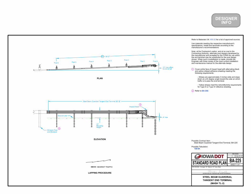
INFODESIGNER
2 BA-200
NEAREST TRAFFIC
ELEVATION
PLAN
LAPPING PROCEDURE
108-8A
1
Impact Head
1
Ground Line
ET = 35'-2"
and Blockout
W-beam Post2
BA-200.Refer to
for Type III or Type IV reflective sheeting.
- Yellow stripes meet the retroreflectivity requirements
traffic is to pass the end terminal.
down at a 45 degree angle toward the side on which
- Stripes are approximately 3 inches wide and slope
following requirements:
and yellow striped adhesive sheeting meeting the
Cover entire face of impact head with alternating black
455.02
and maintenance manual for the alternate design.
Engineer with three copies of the most current installation
shown. When such a substitution is made, provide the
the end terminal may be substituted for the post design
the manufacturer and accepted by the FHWA for use within
Contracting Authority, alternate post designs developed by
Note: at the Contractor's option, and at no cost to the
manufacturer's recommendations.
specifications. Install end terminals according to the
Use materials meeting the respective manufacturer's
for a list of approved sources.Refer to Materials I.M.
Possible Tabulation:
Steel Beam Guardrail Tangent End Terminal, BA-225
Possible Contract Item:
108-8A
BA-225
REVISION
10-17-17
SHEET 1 of 1
REVISIONS:Changed 16" offset to 12" max offset.
APPROVED BY DESIGN METHODS ENGINEER
STANDARD ROAD PLAN
1
(MASH TL-2)
TANGENT END TERMINAL
STEEL BEAM GUARDRAIL
Post 6Post 5
Post 4Post 3
Post 2Post 1 Post 0
HeightMounting31"
"21
Steel Beam Guardrail Tangent End Terminal 38'-3
to end of rail12" max offset
4" max

NEAREST TRAFFIC 2
1
3
LAPPING PROCEDURE
12'-6''
1'-3''
VARIABLE FLARE
4
EW-301
BA-200
EW-301
SI-211
.For general guardrail details, see
.For grading requirements, see
.Install delineators and object markers according to
BA-200
SI-211
BA-201
BA-202
BA-205
BA-206Rail Elements
or Bridge Rail
Concrete Barrier
Rail Elements
INFODESIGNER
LOCATION STATION Connection
Bolted
VT1
Rail Splice
(37'-6'')
Transition Section
Steel Beam Guardrail Barrier
1
2
Rail Splice
Face of Guardrail
ETVT2
VF
Installation Line
4
3
Rail Splice
(varies)Steel Be
am GuardrailPay leng
th for:
(Multiple of 6'-3")
Variable Tangent
(Multiple of 6'-3")
Variable Flare
Variable Tangent
5
5
108-8A
BA-206
BA-205
BA-202
BA-201
" if VF is used.21
of 53'-1
" if no VF is used. Minimum VT1 21
Minimum VT1 of 40'-7
.See
.See
bridge rail end sections.
for connections to concrete barriers and See
.See
")21
(40'-7
for Cable ConnectionSteel Beam Guardrail Flared End Te
rminalor
")21
(50'-9Steel Beam Guardrail Tangent End T
erminal
(47'-8" for Tangent, 37'-6" for Flared)
End Terminal
Possible Tabulation:
Steel Beam Guardrail Flared End Terminal, BA-206
Steel Beam Guardrail Tangent End Terminal, BA-205
Steel Beam Guardrail End Anchor, Bolted
Steel Beam Guardrail Barrier Transition Section, BA-201
Steel Beam Guardrail
Possible Contract Items:
108-8A
BA-250
REVISION
10-18-16
SHEET 1 of 1
REVISIONS:Added MASH TL-3 designation to title. Changed Barrier Transition
Section contract item to specify BA-201.
APPROVED BY DESIGN METHODS ENGINEER
STANDARD ROAD PLAN
6
(MASH TL-3)
OR BRIDGE RAIL END SECTION
INSTALLATION AT CONCRETE BARRIER
STEEL BEAM GUARDRAIL

INFODESIGNER
APPROACH TRAFFIC
1
LAPPING PROCEDURE
12'-6''
1'-3''
VARIABLE FLARE
OBSTACLE
L
TVT1
O
Rail Splice
Rail Splice2
1
1
APPROACH TRAFFIC
TRAILING TRAFFIC
A
A
AT
T
ET
VT1 VF
VF ETVT2
VT2
AT POST LOCATION STATION
2
2
(Multiple of 6.25')
Variable Tangent(Multiple of
6.25')Variable
FlareMin. 12.5')
(Multiple of 6.25'
Variable Tangent
(Multiple of 6.25')
Variable Flare
(Multiple of 6.25')
Variable Tangent
EW-301.
BA-205
BA-206
BA-200BA-200
EW-301
SI-211
.For general guardrail details, see
.For grading requirements, see
.Install delineators and object markers according to
BA-206
BA-205
.See
.See
(varies)Steel Bea
m GuardrailPay leng
th for:
OD
Installation LineFace of Guardrail
Rail Elements Rail Elements
Edge of Traveled Way
")21(40'-7
for Cable Connection
Steel Beam Guardrail Flared End Terminal
or
")21(50'-9
Steel Beam Guardrail Tangent End Terminal
")21
(40'-7
for Cable ConnectionSteel Beam Guardrail Flared End Te
rminalor
")21
(50'-9Steel Beam Guardrail Tangent End T
erminal
SI-211
108-8B
Possible Tabulation:
Steel Beam Guardrail Flared End Terminal, BA-206
Steel Beam Guardrail Tangent End Terminal, BA-205
Steel Beam Guardrail
Possible Contract Items:
108-8B
(47'-8" for Tangent, 37'-6" for Flared)
End Terminal
(47'-8" for Tangent, 37'-6" for Flared)
End TerminalMin. 12.5')
(Multiple of 6.25'
Variable Tangent
BA-251
REVISION
04-19-16
SHEET 1 of 1
REVISIONS:Updated layout and possible contract items to reflect update to MASH
approved end terminals. Added a min. 12.5 to VT1t.
APPROVED BY DESIGN METHODS ENGINEER
STANDARD ROAD PLAN
3
(TWO-WAY PROTECTION)
INSTALLATION AT SIDE OBSTACLE
STEEL BEAM GUARDRAIL
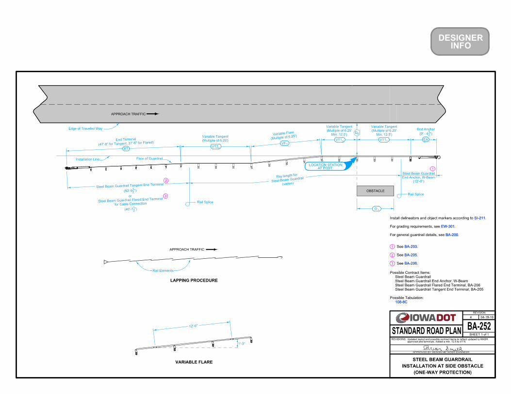
INFODESIGNER
LAPPING PROCEDURE
12'-6''
1'-3''
VARIABLE FLARE
APPROACH TRAFFIC
2
1 BA-203
1
A
A TVT1 VT1
VT2 ET
A
L
VF
O
Rail Splice
AT POST LOCATION STATION
3
3
Min. 12.5')
(Multiple of 6.25'
Variable Tangent
(Multiple of 6.25')
Variable Flare
(Multiple of 6.25')
Variable Tangent
BA-200
EW-301
SI-211
.For general guardrail details, see
.For grading requirements, see
.Install delineators and object markers according to
EW-301
BA-200
SI-211
BA-205
BA-206BA-206
BA-205
BA-203
.See
.See
.See
2
108-8C
EA
End Anchor
(9' - 412")
APPROACH TRAFFIC
OBSTACLERail Splice
(12'-6'')
End Anchor, W-Beam
Steel Beam Guardrail
(varies)Steel Be
am GuardrailPay leng
th for:
")21
(40'-7
for Cable ConnectionSteel Beam Guardrail Flared End Te
rminalor
")21
(50'-9
Steel Beam Guardrail Tangent End Terminal
Min. 12.5')
(Multiple of 6.25'
Variable Tangent
Possible Tabulation:
Steel Beam Guardrail Tangent End Terminal, BA-205
Steel Beam Guardrail Flared End Terminal, BA-206
Steel Beam Guardrail End Anchor, W-Beam
Steel Beam Guardrail
Possible Contract Items:
108-8C
Edge of Traveled Way
OD
Face of GuardrailInstallation Line
Rail Elements
BA-252
REVISION
04-19-16
SHEET 1 of 1
REVISIONS:approved end terminals. Added a min. 12.5 to VT1t.Updated layout and possible contract items to reflect updated to MASH
APPROVED BY DESIGN METHODS ENGINEER
STANDARD ROAD PLAN
4
(ONE-WAY PROTECTION)
INSTALLATION AT SIDE OBSTACLE
STEEL BEAM GUARDRAIL
(47'-8" for Tangent, 37'-6" for Flared)
End Terminal

2
Installation LineEdge of Traveled Way
Automatic Signal Footing
C of RoadwayL
TrackofLC
LAPPING PROCEDURE
PLAN
TRAFFIC
EW-301
BA-200
EW-301
.For additional guardrail requirements, refer to
.For grading requirements, refer to
BA-200
BA-205
NEAREST TRAFFIC
")21
(50'-9Steel Beam Guardrail End Term
inal
(18'-9")
Thrie-Beam End Anchor
BA-204
21
LOCATION STATION
Possible Tabulation:
Object Marker, Type 3
Object Marker, Type 2
Delineator, Rigid - Type I
Incidental to Steel Beam Guardrail End Anchor, Thrie-Beam:
Steel Beam Guardrail Tangent End Terminal, BA-205
Steel Beam Guardrail End Anchor, Thrie-Beam
Possible Contract Items:
108-8D 108-8D
OD
")21
(Min. 21'-10
Variable Tangent
VT
BA-204
BA-205
.Refer to
.Refer to 1
INFODESIGNER
BA-253
REVISION
04-19-16
SHEET 1 of 1
REVISIONS:Updated to MASH approved end terminal. Removed circle note 1. Added VT.
APPROVED BY DESIGN METHODS ENGINEER
STANDARD ROAD PLAN
3
INSTALLATION AT RAILROAD SIGNAL
STEEL BEAM GUARDRAIL
(47'-8" for Tangent)End Terminal
ET

NEAREST TRAFFIC
2
1
3
LAPPING PROCEDURE
12'-6''
1'-3''
VARIABLE FLARE
EW-301
BA-200
EW-301
SI-211
.For general guardrail details, see
.For grading requirements, see
.Install delineators and object markers according to
BA-200
SI-211
BA-221
BA-202
BA-225
Rail Elements
or Bridge Rail
Concrete Barrier
Rail Elements
LOCATION STATION Connection
Bolted
VT1
Rail Splice
1
2
Rail Splice
Face of Guardrail
ETVT2
VF
Installation Line
3
Rail Splice(varies)
Steel Beam Guardrail
Pay length for:
(Multiple of 6'-3")
Variable Tangent
(Multiple of 6'-3")
Variable Flare
Variable Tangent
108-8A
EW-301
SI-211
BA-260
REVISION
10-18-16
SHEET 1 of 1
REVISIONS:NEW
APPROVED BY DESIGN METHODS ENGINEER
STANDARD ROAD PLAN
NEW
(MASH TL-2)
OR BRIDGE RAIL END SECTION
INSTALLATION AT CONCRETE BARRIER
STEEL BEAM GUARDRAIL
")21
(21'-10
Transition Section
Steel Beam Guardrail Barrier
")21
(38'-3Steel Beam Guardrail Tangent End T
erminal
(35'-2" for Tangent)End Terminal
Possible Tabulation:
Steel Beam Guardrail Tangent End Terminal, BA-225
Steel Beam Guardrail End Anchor, Bolted
Steel Beam Guardrail Barrier Transition Section, BA-221
Steel Beam Guardrail
Possible Contract Items:
108-8A
BA-225
BA-202
BA-221
of 37'-6" if VF is used.
Minimum VT1 of 25'-0" if no VF is used. Minimum VT1
.See
bridge rail end sections.
for connections to concrete barriers and See
.See
4
4
INFODESIGNER

BA-351
REVISION
04-20-10
SHEET 1 of 2
REVISIONS:New. Replaces RE-88.
APPROVED BY DESIGN METHODS ENGINEER
STANDARD ROAD PLAN
New
HIGH TENSION CABLE GUARDRAIL
108-9A
Possible Contract Items:
High Tension Cable Guardrail
High Tension Cable Guardrail, End Anchor
Possible Tabulation:
108-9A
(length varies)
Protection Length
(length varies)
End Anchor
D
ROADSIDE OBSTACLE, TWO-WAY PROTECTION
O
TRAILING TRAFFIC
Edge of Pavement
High Tension Cable Guardrail
APPROACH TRAFFIC
High Tension Cable Guardrail
End Anchor
APPROACH TRAFFIC
Edge of Pavement
DO
End Anchor End Anchor
OBSTACLE
ROADSIDE OBSTACLE, ONE-WAY PROTECTION
Protection Length
(length varies) (length varies)
LOCATION STATION
LOCATION STATION
C OA
C
AC O
C C T
OBSTACLE

BA-351
REVISION
04-20-10
SHEET 2 of 2
REVISIONS:New. Replaces RE-88.
APPROVED BY DESIGN METHODS ENGINEER
STANDARD ROAD PLAN
New
HIGH TENSION CABLE GUARDRAIL
TRAFFIC
Edge of Pavement
Edge of PavementTRAFFIC
End Anchor
Protection Length
Protection Length
MEDIAN OBSTACLE PROTECTION
(length varies)
End Anchor
(length varies)
High Tension Cable Guardrail
High Tension Cable Guardrail
End Anchor
(length varies)
End Anchor
(length varies)
LOCATION STATION
LOCATION STATION
C OC
A
DO
DO
C O
C A

1
2
2" Dia. Hole
15" 15"
5'
Tie-Down Angle (Typ.)PCC Fill
Barrier Marker
Anchorage (Typ.)
Traffic Side
20'
Barrier Marker
Lifting Assembly
2
1
26"
15" 15"
5'
Splice Plate
Chamfer 1" x 2"
max.
PCC Fill
root opening5'
Typ.
12"
A
A
Lifting Assembly Chamfer 1" x 2"
Splice Plates
12"max.
6"
4"
Anchorage (Typ.)
1
ELEVATION
PLAN
SECTION A-A
Edge of Dropoff
or Hazard
PCC Fill
Barrier Marker
2"
HP 14 X 73
Tie-Down Angle
See
Table A
Anchorage (Typ.)
2
1
"169
3
"21
6
"169
3
"21
2
)21
(L6 X 4 X
" Dia.41
1
"41
"41
" max.81
)21
(L6 X 4 X
5'
"85
13
"41
29
"41
29
Barrier Rail, Steel."
when required, is to be in the price bid for "Temporary
with an approved non-shrink grout. The cost of anchorage,
equivalent). Following removal of anchorage, fill all holes
3/4" Red Head Multi-Set II drop-in anchor (or approved
dia. x 1 3/4" long ASTM A307 Grade B heavy hex bolt, and a
Anchorage consisting of a washer plate as shown, a 3/4"
install anchorage on traffic side of barrier only.
When installed in one-way traffic situations use and
Anchorage for use on bridge decks or PCC pavement only.
c
Possible Tabulation:
Temporary Barrier Rail, Steel
Possible Contract Item:
108-33108-33
completion of work.
the property of the Contractor. Remove from the site upon
Unless stated otherwise, the barrier rail sections remain
one hour of notification of need.
to realign barrier which has been struck. Initiate within
on call and available 24 hours a day, each day of the week,
Provide for an approved monitoring schedule with a person
depending on the method of bulkheading.
fill shown are approximate and may be rough or slumped
Deposit by a method approved by the Engineer. Limits of the
commercial ready-mix with a minimum f ’ = 2500 psi. Use an Iowa DOT Construction Specification mix or a
Use steel meeting the requirements of ASTM A36.
"Temporary Barrier Rail, Steel."
installing and maintaining markers in the price bid for
damaged or missing units. Include all costs for furnishing,
line. Maintain the markers and promptly repair or replace
oncoming traffic. Use a color to match the adjacent edge
approved by the manufacturer. Place Markers to face
on this sheet and attach to the barrier in a manner
Furnish and install Barrier Markers. Place Markers as shown
Traffic Side
BA-400
REVISION
04-16-13
SHEET 1 of 2
REVISIONS:Defined dropoff on sheet 2.
APPROVED BY DESIGN METHODS ENGINEER
STANDARD ROAD PLAN
1
(STEEL)
TEMPORARY BARRIER RAIL

6"
2"
6"
Washer Plate
BARRIER CONNECTION
TOP SECTION BARRIER CONNECTION
SIDE SECTION
Connection Rod
Splice Plates
3"
Top Plate
20"
3"
3"
Connection Rod
CONNECTION ROD ASSEMBLY
" Dia. Hole
13"
"
2" Dia. Holes
LIFTING ASSEMBLY
3"
7"
"167
"21
2
"85
5
"21
"43
"21
"21
" U-Bolt43
" I.D. Bend21
4
"21
2
"21
2
"43
6 "41
6
"81
4"
83
"21
6
" Dia. Hole85
1
"43
"41
"41
" dia.21
1
16 13
"83
12
" Top Plate41
" WASHER PLATE163
" SPLICE PLATE21
1615
2
Traffic Side
TABLE A
ANCHORAGE REQUIREMENTS
Min. offset
where T
BR
is U
nanchore
d
Min. offset
where T
BR
is A
nchore
d
N/A
3"
3"
24"
24" 10''
18''
1''
18''
10'' 6''
6''
N/A
6''
6''
Obstacle
Depth
Dro
poff
A dropoff is a slope of 2H:1V or steeper*
*Dropoff
pavementfrom
bridgefrom
Fixed vertical object
BA-400
REVISION
04-16-13
SHEET 2 of 2
REVISIONS:Defined dropoff on sheet 2.
APPROVED BY DESIGN METHODS ENGINEER
STANDARD ROAD PLAN
1
(STEEL)
TEMPORARY BARRIER RAIL

" Chamfer43
1
2
3
BA-401
1 inch radius allowed.
Lifting hole. 4 inch diameter PVC Pipe.
Type A ● ● Date Manufactured (Month and Year) ● Manufacturer Identification
information in the marking:
two loop bars at the bottom. Include the following
end of the barrier having one loop bar at the top and
manufacturing information. The “marked end” is that Permanently mark one end of each rail section with
bid for "Temporary Barrier Rail, Concrete".
Include the cost of anchorage, when required in the price
cubic yards.
Estimated quantity of concrete for one taper section is 0.6
to 50 mph.
within 10 feet of traffic on facilities with speed limits 40 mph
of traffic on facilities with speed limits 55 mph or greater, nor
Tapered end section is not designed for use within 30 feet
approved non-shrink grout.
Following removal of anchorage, fill all holes with an
site upon completion of work.
shall be the property of the Contractor. Remove from the
Unless stated otherwise in the plans, the barrier rail sections
within one hour of notification of need.
to realign barrier which has been struck. Initiate service
on call and available 24 hours a day, each day of the week,
Provide for an approved monitoring schedule with a person
not lift or move using loop bars 6d1, 6d2 or 6d3.
Use Grade 60, ASTM A615 for all other reinforcements. Do
" of the plan dimensions.81
Install loops within
" pin bend diameter. 21
a 180 degree bend test using a 3
80 ksi, a minimum 14% elongation in 8 inches, and passing
not less than 1.25 times the yield strength but a minimum of
with a minimum yield strength of 60 ksi, a tensile strength of
" smooth steel bars 43
For loop bars 6d1, 6d2, and 6d3, use
Possible Tabulation:
Temporary Barrier Rail, Concrete
Possible Contract Item:
108-33108-33
BA-401
12"
24"
1
1
17"
12" 12" 12"
C
Void area
See Connection Pin
Spacing
Blockout
See Chamfer Detail
Assembly Details
A
"Marked End"
1
8"
B
A
24"
2-4c1
2-5b1
4a1
3
1-5b1
8"
1-5b1
2-4c1
3
17"
22"
32"
4'-3"
6"
4'-3" 4'-3"
12'-6"
6"
4a1 Spa.
6a2 (in pairs)
4'-3"
8"
3"
3"
6a21"
3"
2"
6a2
2"8"
3"
7"
"Marked End"
"Marked End"
4a1
4a1
5b1
12'-6"
5b1
4c1
5b1
6d3
4c1
6a26a2
5b1
4c1 5b1
6d3
4a1
5b1
4c1
5b1
4a16d3
4c1
5b1
1"
2-5b1
3
6d1
6d1
6d2
5b1
6d2
4a1
5"
3
B
2
7"
1"1"1"
Lifting Slot6a26d1
6d2
6d1
6d2
6d3
2Blockout (both sides)
C
9"
4"
CHAMFER DETAIL
PLAN
ELEVATION
SECTION C-CStirrup Placement
SECTION A-ALifting Slot
"41
2
"21
22
''43
"87
2
"85
14
"21
6
2" clear
1" clear to 6a2 bar
" min. clear
43
1
SECTION B-BStirrup Placement
" min. clear
43
1
"87
2
"85
14
8"
"21
6
2" clear
1" clear to 6a2 bar
2" min. clear
4a1
2" dia. Hole 4" typ.
"21
22
" Wooden Block85
Set with 3
"21
7
"21
4
to outside edge of loop bar
" measured from face of rail81
" ± 83
3
"21
25
9" "21
21 "21
21 "21
21 "21
21 8" 9" 9"
4" typ.
24" 24"4'-3"
(Elevation)
BARRIER CONNECTION
BA-401
REVISION
04-16-13
SHEET 1 of 4
REVISIONS:Defined dropoff on sheet 3.
APPROVED BY DESIGN METHODS ENGINEER
STANDARD ROAD PLAN
1
(PRECAST CONCRETE)
TEMPORARY BARRIER RAIL

Barrier Rail, Concrete."
maintaining markers in the price bid for "Temporary
units. Include costs for furnishing, installing and
promptly repair or replace any damaged or missing
adjacent edge line in color. Maintain the markers and
Markers to face oncoming traffic and match the
barrier in a manner approved by the manufacturer.
Furnish and install Barrier Markers. Attach to the
with Strap Anchorage.
2-loop barriers (previous designs) or in conjunction
Retainer bolt & nut are required for connections with
5
4
16"
Barrier Marker
16"
12"16"
28"
Connection Pin
28"
Retainer Bolt
4
5
Marker Centered on Unit
2"
E60
4"
4
8"
D=3"
33"
7"
2" 2"
6d3
6d2
6d1
Top Plate
BARRIER MARKER PLACEMENT
CONNECTION PIN ASSEMBLY
" Top Plate 21
6a2
4a1
Per 12'-6" Barrier Section
Size
Bar
Bar Bars
of
No.
Shape
4a1
6 25.5
LOOP ASSEMBLY
26d3
6
6
2
2
REINFORCING A615 Gr. 60
Ft.
Length
8'-6"
35"
Lbs.
Weight
7'-7"
12'-2"
6'-0"
8'-5"
12'-2"
5
4 12
4 16.34c1
5b1 38.1
48.1
3
6d2
6d1
22.8
25.3
66a2
2
6 26.3
(Marked end shown, invert for other end.)
Elevation
bars unless otherwise noted.)
(Dimensions are out to out of
BENT BAR DETAILS
(A36 Steel - 10.9 lbs. each)
CONNECTION PIN
6d1, 6d2, 6d3
Plan
Traffic Side
Centered on Plate
" dia. hole83
1
"21
2
"21
1for retainer bolt
" dia. hole85
" dia.41
1
"21
"21
2
"21
2
''41
(ASTM A490, Grade 8)
" dia. bolt & nut21
RETAINER BOLT & NUT
L
L
C Bar
3" to
C Bar17"
"21
34
"43
33
"43
"43
17"
43
20
"41
5
"85
18
"81
3
"21
4
"21
15
"83
4
"815
"41
D=4
"21
D=6
"41
4
"43
D=2
BA-401
REVISION
04-16-13
SHEET 2 of 4
REVISIONS:Defined dropoff on sheet 3.
APPROVED BY DESIGN METHODS ENGINEER
STANDARD ROAD PLAN
1
(PRECAST CONCRETE)
TEMPORARY BARRIER RAIL

" core bit.85
Pre-drill holes for stakes with 1
3 stakes required per rail section.
" dia. x 5" min.).43
Titen HD Wedge Bolt (
" min.) OR Simpson 21
" dia. x 443
Large Diameter Tapcon (
" long ASTM A325 structural bolt OR Red Head 43
x 1
'' dia. 43
inch Red Head Multi-Set II drop-in anchor with 43
8
7
6
2"
See Table A
3"
3"
3"
Stop Plate
Traffic Side
3"
See Table A
8
8
36"
16" 16"
10"
2"
6
Bend Line (typ.)
20"
Edge of Dropoff
Tie-Down Strap
7
3"
Stake
Traffic Side
STAKE ANCHORAGE
STRAP ANCHORAGE
END VIEW
STAKE
" STOP PLATE21
TYPICAL SECTION
TABLE A
ANCHORAGE REQUIREMENTS
(after bending)
TIE-DOWN STRAP
(before bending)
TIE-DOWN STRAP
PCC Pavement
Bridge Decks
For use on:
PCC Pavement
Composite Pavement
HMA Pavement (2'' min. thickness)
For use on:
68°
68°
" dia.21
1
"21
38"21
1
"21
1
''41
Anchor (typ.)
Pin Assembly
Connection
" dia.87
"163
" dia.83
1"
163 "
163
" dia.87
"21
10
"21
2
"21
2
"21
103"2"
A36 Steel Plate
"41
" x 341
3" x
" inside rad.41
"83
" rad. to Inside41
A36 Steel Strap
'' x 36''41
3'' x
A36 Steel Plate
"41
" x 341
3" x
"21
1
Edge of Dropoff
or Fixed Vertical Object
or Fixed Vertical Object
Min. offset
where T
BR
is U
nanchore
d
Min. offset
where T
BR
is A
nchore
d
N/A
3"
3"
24"
24"
1''
6''
6''
N/A
6''
6''
Obstacle
Depth
Dro
poff
A dropoff is a slope of 2H:1V or steeper*
*Dropoff
pavementfrom
bridgefrom
Fixed vertical object
BA-401
REVISION
04-16-13
SHEET 3 of 4
REVISIONS:Defined dropoff on sheet 3.
APPROVED BY DESIGN METHODS ENGINEER
STANDARD ROAD PLAN
1
(PRECAST CONCRETE)
TEMPORARY BARRIER RAIL
24''
45''
45''
24''

1 inch radius allowed.3
17"32"
12"
12"
12"
18"
14"
18"18"18"
32"
22"
16"
33"
16"
TRAFFIC
6d3
4d2
4v15f3
6d1
6d24v2
4v3
12"
PLAN
4v4
4v64v5
4f1
7"12'-6''
5f3
4f2
4f1
See Detail 'A'
3
3
Spaces
2 Equal
5'-4"
6"
8"
6"
6"
12'-6"
3"
8"
5"
See chamfer detail
Possible Curb
8''
Center of Gravity
2" V bar Spa.
4f13"
3"6d2
6d3
for stirrup assembly
2 at each size required
A
6d1
8"
5"
B
PERSPECTIVE VIEW
DETAIL 'A'
FRONT ELEVATION END SECTION
Plan
4v_ bars
Elevation
TAPERED END SECTION
Per 12'-6" Barrier Taper Section
20"
23"
27"
17"
4v5
4v4
13"
4v6
26"
33"
30"
4
4
2
2
4
4v1
4v2
4
4
2
4.2
3.7
16.0
4.5
3.3
2
2 2.9
2.6
5f3
4f2 4
44v6
Size
BarBar Bars
of
No.
Shape
5
4v5
2
4v3
4v4
4
2
2
4f1
1
10.0
Bar
8'-6"
1"10"
7'-7"
16
8'-5"
LOOP ASSEMBLY
4v1
B
4v3
4v2
A
7'-6"
3'-4"
12'-0"
11'-9"
3'-2"
ft.
Length
12.3
REINFORCING A615 Gr. 60
lbs.
Weight
6d1
1
1
12.86d3
6
12.6
6d2
6
11.4
169°
LC
"43
4'-2
"21
22
" clear21
1
2" clear
"21
22
"41
2
2" min. clear
2" min. clear
(Dimensions are out to out of bars unless otherwise noted.)
BENT BAR DETAILS
" measured from face of rail to outside edge of loop bar.81
" ± 83
3
" chamfer43
Section A-A
the Contractor.
for details. Location to be determined by
Provide two lifting slots. See
Invert loop bars for other end.)
(For connection to "marked end" of barrier.
SIDE ELEVATION
LC Bar
3" to
LC Bar
17" to
"43
"43
33
"21
34
"43
20
"43
17
"41
4
"43
D=2
invert for other end)(Connection to "Marked End" shown,
6d1, 6d2, 6d3
"41
1
"85
1
"87
1
"83
2
"43
2
"21
24
BA-401
REVISION
04-16-13
SHEET 4 of 4
REVISIONS:Defined dropoff on sheet 3.
APPROVED BY DESIGN METHODS ENGINEER
STANDARD ROAD PLAN
1
(PRECAST CONCRETE)
TEMPORARY BARRIER RAIL

108-30
Possible Tabulation:
Temporary Crash Cushion
Embankment In Place
Possible Contract Items:
108-30
6'-0''
35'-0''
EMBANKMENT DIMENSIONSBarrel Installation Line
35'-0''
3'-0''
1
5°Barrel Installation Line
1
10°
V
Width
Shoulder
EMBANKMENT PLAN
2:1 maximum
3:1 preferred,
Approach Traffic
X
Approach Traffic
10°
20:1
Edge of Pavement
Edge of Shoulder
Z
Y
of Embankment
Possible Toe
15°
4:1
OBSTACLE
W
max
X
Approach Traffic
Y
4
3
Widths:
For Obstacle
Required
Layouts
Barrel
Sand
2
1
Where distance to obstacle is 15 feet or greater from edge of traveled way:
Where distance to obstacle is less than 15 feet from edge of traveled way:
3'-7" - 10'-7"
3'-6" or less
W Z
negative)
(must not be
26'-6"
25'-9"
17'-10" - 32'-3"
10'-8" - 17'-9"
25'-0"
24'-3"
Edge of Special Shaping
Angle of Barrel Installation Line is measured from a line parallel to roadway centerline.
BARREL INSTALLATION LINE LAYOUT
INFODESIGNER
2:1 max.
3:1 pref,
EMBANKMENT TYPICAL SECTION
Embankment
Toe of
120
Edge of Special Shaping
Edge of Shoulder
V + 3'-3"
V + 10'-0"
V + 17'-0"
V + 24'-0"
V + 5'-3"
V + 12'-3"
V + 19'-3"
V + 26'-3"
3.73 V + 12'-0"
3.73 V + 38'-0"
3.73 V + 64'-0"
3.73 V + 89'-0"
LOCATION STATION
X
Y
dimension.
dimension equals to roadway centerline. In this case,
space is limited, Barrel Installation Line may be parallel
For obstacles located within the traveled way where
BA-500
REVISION
04-19-16
SHEET 1 of 2
REVISIONS:Changed formula in Column Z.
APPROVED BY DESIGN METHODS ENGINEER
STANDARD ROAD PLAN
1
SAND BARREL
TEMPORARY CRASH CUSHIONS
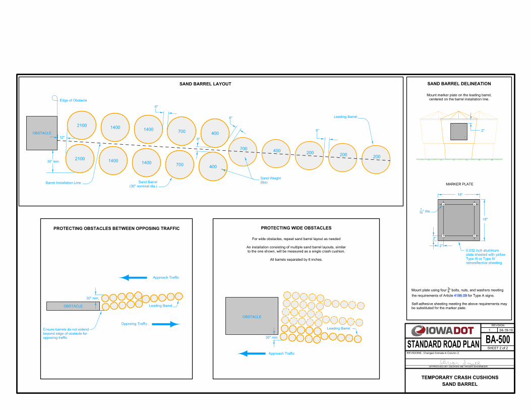
SAND BARREL DELINEATION
MARKER PLATE
200200
200400
700
400
400
700
700
1400
1400
1400
1400
2100
2100
30" min.
30" min.
Leading Barrel
Leading Barrel
OBSTACLE
Approach Traffic
Approach Traffic
Opposing Traffic
OBSTACLE
18"
2"
2"
18"
PROTECTING WIDE OBSTACLES
SAND BARREL LAYOUT
PROTECTING OBSTACLES BETWEEN OPPOSING TRAFFIC
centered on the barrel installation line.
Mount marker plate on the leading barrel,
2"
retroreflective sheeting
Type III or Type IV
plate sheeted with yellow
0.032 inch aluminum
6"
Edge of Obstacle
6"
6"
6"
(lbs)
Sand Weight
(36" nominal dia.)
Sand Barrel
30" min.
12"
Barrel Installation Line
Leading Barrel
OBSTACLE
All barrels separated by 6 inches.
to the one shown, will be measured as a single crash cushion.
An installation consisting of multiple sand barrel layouts, similar
For wide obstacles, repeat sand barrel layout as needed
" dia.167
4186.09
be substituted for the marker plate.
Self-adhesive sheeting meeting the above requirements may
for Type A signs.the requirements of Article
" bolts, nuts, and washers meeting 83
Mount plate using four
4186.09
opposing traffic
beyond edge of obstacle for
Ensure barrels do not extend
BA-500
REVISION
04-19-16
SHEET 2 of 2
REVISIONS:Changed formula in Column Z.
APPROVED BY DESIGN METHODS ENGINEER
STANDARD ROAD PLAN
1
SAND BARREL
TEMPORARY CRASH CUSHIONS