bankhead depot phase 2 office accomodation 6700 appendix d or bs en 806-3. submit proposals
TRANSCRIPT

Bankhead Depot Phase 2 Office Accomodation
12 July 2011
Table of Contents
Title Page
P Building fabric sundries 4
6Holes, chases, covers and supports for servicesP31
8Services painting systemsP32
S Piped supply systems 11
13Hot and cold water supply systemsS10
19Natural gas supply systemsS32
T Mechanical heating, cooling and refrigeration 22
24Heating systemsT10
27Gas and oil fired boilersT20
29Heat emittersT30
31Variable refrigerant flow systemsT41
34Chilled water systemsT50
36Central refrigeration plantT60
U Ventilation and air conditioning systems 38
40Ventilation systemsU10
43Air conditioning systemsU30
46Fan coil unitsU41
48Local air conditioning systemsU60
52Air ductwork and ancillariesU80
57Air handling unitsU81
60FansU82
62Silencers and acoustic treatmentU87
64Air terminal devicesU88
Y General engineering services 67
69PipelinesY10
76Pipeline ancillariesY11
85Mechanical cleaning and chemical treatmentY12
87PumpsY20

90Trace heating tapesY24
92Mechanical thermal insulationY30
98Mechanical plant and equipment identificationY32
101Flues and chimneysY35
103Mechanical engineering services control and management systems
Y40
123Mechanical commissioningY50

P
Building fabric sundries

P31
Holes, chases, covers and supports for services
P31 Holes, chases, covers and supports for services
To be read with Preliminaries/General conditions
PRODUCTS
EXECUTION
610 COORDINATION Locations and dimensions of holes and chases for services: Submitdetails to Contract Administrator.
650 HOLES, RECESSES AND CHASES IN MASONRY
• Locations: To maintain integrity of strength, stability and sound resistance of construction.
• Sizes: Minimum needed to accommodate services.- Holes (maximum): 300 x 300 mm.
• Walls of hollow or cellular blocks: Do not chase.
• Walls of other materials:- Vertical chases: No deeper than one third of single leaf thickness, excluding finishes.- Horizontal or raking chases: No longer than 1 m. No deeper than one sixth of the singleleaf thickness, excluding finishes.
• Chases and recesses: Do not set back to back. Offset by a clear distance at least equal tothe wall thickness.
• Cutting: Do not cut until mortar is fully set. Cut carefully and neatly. Avoid spalling, crackingand other damage to surrounding structure.
670 NOTCHES AND HOLES IN STRUCTURAL TIMBER• General: Avoid if possible.• Sizes: Minimum needed to accommodate services.• Position: Do not locate near knots or other defects.• Notches and holes in same joist: Minimum 100 mm apart horizontally.• Notches in joists: Locate at top. Form by sawing down to a drilled hole.
- Depth (maximum): 0.125 x joist depth.- Distance from supports: Between 0.07 and 0.25 x span.
• Holes in joists: Locate on neutral axis.- Diameter (maximum): 0.25 x joist depth.- Centres (minimum): 3 x diameter of largest hole.- Distance from supports: Between 0.25 and 0.4 of span.
• Notches in roof rafters, struts and truss members: Not permitted.• Holes in struts and columns: Locate on neutral axis.
- Diameter (maximum): 0.25 x minimum width of member.- Centres (minimum): 3 x diameter of largest hole.- Distance from ends: Between 0.25 and 0.4 of span.
690 INSTALLING PIPE SLEEVES
• Sleeves: Fit to pipes passing through building fabric.
• Material: Match pipeline.
• Size: One or two sizes larger than pipe to allow clearance.
• Finish: Install sleeves flush with building finish. In areas where floors are washed down,install protruding 100 mm above floor finish.
• Masking plates: Fit at visible penetrations, including through false ceilings of occupiedrooms.

P32
Services painting systems
P32 Services painting systems
To be read with Preliminaries/General conditions
130 METAL SURFACE COATING To all unprotected metal service supports and pipeworksusceptible to corrosion
• Surface: Steel.• Initial coats: Contractor's choice.
- Number of coats: 1- Colour: To be selected from manufacturers' standard range .
• Finishing coats: Contractor's choice.- Number of coats: 1- Colour: To be selected from manufacturers' standard range .- Finish: Not applicable.
SYSTEM PERFORMANCE
210 DESIGN
• General: Complete the design of the coating systems in accordance with BS 6150.
• Proposals: Submit schedules, drawings and manufacturer's literature.
220 DESIGN LIFE OF METAL SURFACE COATINGS
• Design life (assuming reasonable wear and tear, and regular maintenance): 7 years
• Environment category in accordance with BS 6150: Interior mild.- Chemical and liquid resistance: Not applicable.
EXECUTION
610 PREPARATION GENERALLY• Standard: In accordance with BS 6150.• Substrates: Sufficiently dry and sound in depth to suit coating.• Efflorescence: Remove.• Dirt, grease and oil: Remove.
- Give notice if surfaces and/ or substrates have been contaminated.• Joints, cracks, holes and other depressions:
- Fill with stoppers and/ or fillers. Work well in and finish off flush with surface.- Provide smooth finish.
• Water based stoppers and fillers:- Apply before priming unless recommended otherwise by manufacturer.- If applied after priming: Patch prime.
• Oil based stoppers and fillers: Apply after priming.
• Surface irregularities: Finish smooth.
• Dust, particles and residues from abrasion: Remove.
• 'Wet paint' signs and barriers: Locate where necessary.
635 SERVICE EQUIPMENT, FIXTURES AND FITTINGS
• Preparation:- Items to be removed: Grilles, coverplates and other surface mounted fixtures. and Plantlabels and/ or signage.- Surfaces to be cleaned: None.- Surfaces not to be coated: Radiator valves and stop valves and Hinges .
645 PREPARING PREVIOUSLY COATED SURFACES• Standard: In accordance with BS 6150, clause 11.5 and tables 19 and 20.• Removing coatings: Do not damage substrate and adjacent surfaces or adversely affect
subsequent coatings.• Existing coatings on ironmongery:
- Remove old coating marks. Clean and polish.- Do not remove hinges.- Refix ironmongery on completion.
• Loose, flaking or otherwise defective areas: Carefully remove to leave a firm surface.• Alkali affected coatings: Completely remove.• Problematic substrates: Give notice of the following:
- Coatings suspected of containing lead.- Substrates suspected of containing asbestos.- Significant rot, corrosion or other degraded substrates.
• Retained coatings: Remove dirt, grease and contaminants.• Gloss coated surfaces: Form a key for subsequent coat.• Partly removed coatings:
- Additional preparatory coats: Apply to restore original film thicknesses.- Junctions: Make surfaces flush.
• Completely stripped surfaces: Prepare as for uncoated surfaces.
655 PREPARING PREVIOUSLY COATED STEEL
• Existing defective coatings including primers: Remove to leave a firm edge and cleanbright metal.
• Sound coatings: Form a key for subsequent coat.
• Corrosion and loose scale: Remove to leave bare metal.
• Residual rust: Remove.
• Remaining areas: Degrease.
• Bare areas: Re-prime as soon as possible.
665 PREPARING UNCOATED STEEL - MANUAL CLEANING
• Oil and grease: Remove.
• Corrosion, loose scale, welding slag and spatter: Remove.• Residual rust: Treat using a proprietary removal solution.• Primer: Apply as soon as possible.
680 PREPARING UNCOATED ALUMINIUM OR COPPER OR LEAD• Surface corrosion: Remove and provide suitable surface for coating.
760 APPLYING COATINGS GENERALLY• Conditions: Maintain suitable temperature, humidity and air quality during application and
drying.• Surfaces: Clean and dry at time of application.• Thinning and intermixing of coatings: Not permitted unless recommended by manufacturer.• Overpainting: Do not paint over intumescent strips or silicone mastics.• Priming coats:
- Thickness: To suit surface porosity.- Application: As soon as possible on same day as preparation is completed.
• Finish:- Even, smooth and of uniform colour.- Free from brush marks, sags, runs and other defects.- Cut in neatly.

770 COATING CONCEALED METAL SURFACES• General: Apply additional coatings to surfaces that will be concealed when fixed in place.

S
Piped supply systems

S10
Hot and cold water supply systems

S10 Hot and cold water supply systems
To be read with Preliminaries/ General conditions
GENERAL
110 INCOMING WATER SUPPLY• Water company: as existing.
• Volume flow rate: as existing
• Position of incoming mains water supply: to tank room in Phase 3
130 PUMPED COLD WATER SUPPLY SYSTEM To Phase 2
• Type: Flooded suction or suction lift to directly pressurize hot and cold water systems .
• Water meters: Required.
• Pressure booster sets: As section Y20.
• Pumps: as schedule.
• Storage tank or cistern: as schedule.- Accessories: as schedule.
• Water treatment: Not required.
• Pipelines:- Below ground: As section Y10.- Above ground: As section Y10.
• Pipeline ancillaries: As section Y11.
• Thermal insulation:- Pipelines: As section Y30.- Tanks: As section Y30.
• Vibration isolation: Submit design and cost proposals.• Sanitary appliances: As contract drawings 00/01M(53)001/2 .• Drinking water outlets: all basins/sinks.• Flush control devices: Required.• Water coolers: Not required.• Controls: As section Y40.• Accessories: Trace heating, as section Y24.• Completion:
- Cleaning and chemical treatment: Flushing, as section Y12.- Plant and equipment identification: As section Y32.- Commissioning: Commissioning of cold water supply systems, as section Y50.
140 INSTANTANEOUS HOT WATER SUPPLY SYSTEM ACV boilers as existing• Instantaneous water heater: Gas fired .• Pumps: as schedule.
• Pipelines: As section Y10.
• Pipeline ancillaries: As section Y11.
• Thermal insulation:- Pipelines: As section Y30.
• Sanitary appliances: as schedule.
• Controls: As section Y40.
• Completion:- Cleaning and chemical treatment: Flushing, as section Y12.- Plant and equipment identification: As section Y32.- Commissioning: Commissioning of hot water supply systems, as section Y50 .

SYSTEM PERFORMANCE
210 DESIGN AND DETAILING• Design: Complete the design and detailing of the hot and cold water supply.• Standard: To BS 6700 or BS EN 806-2 and in accordance with HSE publication 'The
control of legionella bacteria in water systems. Approved code of practice and guidance'.• Proposals: Submit drawings, technical information, calculations and manufacturer's
literature.
220 COLD WATER SUPPLY• Incoming mains water supply:
- Site factors: as existing.• Type of system: Pumped from a break cistern or storage provision.• Design parameters: In accordance with CIPHE Plumbing engineering services design
guide.• Daily consumption: 20,000l/day.• Storage capacity: as schedule.
230 INSTANTANEOUS HOT WATER SUPPLY
• Type: Gas fired.
• Water supply: Boosted.
240 CENTRALIZED HOT WATER STORAGE SYSTEM
• System design: Design the system to meet the following requirements:
• Storage capacity: as exisitng.- Type of building: Office and With canteen.- Number of people: approx 330.
• Primary heat source: Capable of raising temperature of water from 10°C to 60°C within onehour.
• Temperature range of stored hot water: 80-90°C.
• Water supply: Boosted.
250 PIPELINE SIZES• Sizing: Calculate sizes to meet simultaneous demand for the building in accordance with
BS 6700 Appendix D or BS EN 806-3. Submit proposals.• Performance:
- Water velocity (maximum): 1.3 m/s for hot water and 2.0 m/s for cold water.- Filling time (maximum) for cold water storage cistern: Submit proposals.

255 DRAW OFF REQUIREMENTS• Baths (G¾):
- Type of supply: n/a.- Discharge rate (design): 0.3 L/s.
• Baths (G1):- Type of supply: n/a.- Discharge rate (design): 0.6 L/s.
• Bidets:- Type of supply: n/a.- Discharge rate (design): 0.2 L/s.
• Dish-washing machines:- Type of supply: Boosted cold.- Discharge rate (design): 0.15 L/s.
• Handbasins (pillar or mixer taps):- Type of supply: Hot and cold.- Discharge rate (design): 0.1 L/s.
• Handbasin (spray or spray mixer taps):- Type of supply: Hot and cold.- Discharge rate (minimum): 0.05 L/s.
• Kitchen sinks (G½):- Type of supply: Hot and cold.- Discharge rate (design): 0.2 L/s.
• Kitchen sinks (G¾):- Type of supply: n/a.- Discharge rate (design): 0.3 L/s.
• Kitchen sinks (G1):- Type of supply: n/a.- Discharge rate (design): 0.6 L/s.
• Shower heads:- Type of supply: Hot and cold.- Discharge rate (minimum): 0.2 L/s.
• Urinal cisterns (each position served):- Type of supply: Cold from cistern.- Discharge rate (design): 0.004 L/s.
• Urinal flushing valve:- Type of supply: Boosted cold.- Discharge rate (design): 0.3 L/s.
• Washbasins (pillar or mixer taps):- Type of supply: n/a.- Discharge rate (design): 0.15 L/s.
• Washing machines:- Type of supply: Boosted cold.- Discharge rate (design): 0.2 L/s.
• WC cisterns (to fill in 2 minutes):- Type of supply: Boosted cold.- Discharge rate (design): 0.13 L/s.
• WC flushing troughs:- Type of supply: n/a.- Discharge rate (design): 0.15 L/s.
• WC pressure flushing valves:- Type of supply: Boosted cold.- Discharge rate (design): 1.5 L/s.
260 COMBUSTION AIR SUPPLY TO GAS APPLIANCES
• Size: Submit proposals.
• Location: Submit proposals.
PRODUCTS
310 DEZINCIFICATION• Fittings, pipelines and equipment located below ground or in concealed or inaccessible
locations: Resistant to dezincification, e.g. gunmetal.
320 WATER METERS in tank room• Standard: To BS EN 14154-1.• Type: In-line meters.• Manufacturer: Contractor's choice .
- Product reference: Contractor's choice.• Size: Submit proposals.• Pressure class: Submit proposals.• Temperature class: Submit proposals.• Metrological class: B.• Connections: Submit proposals.• Indicating device: Type 2 - digital.
• Features: Pulsed output for remote monitoring.
• Accessories: To BS EN 14154-2.
360 INSTANTANEOUS WATER HEATERS, ELECTRIC Staff kitchens
• Standard: To BS EN 60335-2-35, BEAB approved.
• Manufacturer: as schedule.- Product reference: as schedule.
• Type: Single point - mains supply.
• Rating: as schedule.
• Flow rate: as schedule.
• Control: as schedule.
• Outlets: as schedule.
• Casing finish: as schedule.
• Accessories: as schedule.
480 FLUSH CONTROL DEVICES urinals• Manufacturer: as schedule.
- Product reference: as schedule.• Flush rate: Programmable with option for 1-4 flushes/ hour and 12 or 24 hours selectable.• Water supply valve: as schedule.• Sensor unit:
- Material: as schedule.• Movement detector: as schedule.• Power supply: as schedule.
EXECUTION
620 INSTALLATION GENERALLY• Installation: To BS 6700.• Performance: Free from leaks and the audible effects of expansion, vibration and water
hammer.
• Fixing of equipment, components and accessories: Fix securely, parallel or perpendicular to the structure of the building.
• Preparation: Immediately before installing tanks and cisterns on a floor or platform, clear the surface completely of debris and projections.
• Corrosion resistance: In locations where moisture is present or may occur, avoid contactbetween dissimilar metals by use of suitable washers, gaskets, and the like.
630 INSTALLING WATER METERS• Standards: To BS EN 14154-2.• Interconnection to Building Management and Monitoring System (BMMS): Required.
650 INSTALLING GAS FIRED WATER HEATERS• Installation: In accordance with BS 5546.
680 BALANCED FLUE TERMINAL• Opening in external wall: Submit proposals.• Flue guard: Submit proposals.
COMPLETION
910 HYDRAULIC PRESSURE TESTING OF HOT AND COLD WATER SUPPLY SYSTEMS• Standard: To BS 6700.
• Notice (minimum): 24 h.
• Pressure: 1.5 times working pressure.
• Duration of test: 1 h.
980 DOCUMENTATION
• Manufacturers' operating and maintenance instructions: Submit for equipment andcontrols.
• System operating and maintenance instructions: Submit for the system as a whole givingoptimum settings for controls.
• Record drawings: Submit drawings showing the location of circuits and operating controls.
990 OPERATING TOOLS
• Tools: Supply tools for operation, maintenance and cleaning purposes.
• Keys: Supply keys for valves and vents.
995 MAINTENANCE• Servicing and maintenance: Undertake.
- Duration: Until 12 months after Practical Completion.

S32
Natural gas supply systems
S32 Natural gas supply systems
To be read with Preliminaries/ General conditions
GENERAL
110 INCOMING GAS SUPPLY• Gas transporter: as existing.
• Gas supplier: as existing.
• Volume flow rate: as existing.
• Position of meter: as existing.
120 NATURAL GAS SUPPLY SYSTEM to plantroom and kitchen
• Metering: Secondary gas meter.
• Gas pipelines: Low pressure supply.
• Gas valves: Submit design and cost proposals.
• Gas equipment: Safety and control devices.
• Gas outlets: Submit design and cost proposals.
• Completion:- Plant and equipment identification: As section Y32
SYSTEM PERFORMANCE
210 DESIGN• Design: Complete the design of the gas supply system.• Proposals: Submit drawings, technical information, calculations and manufacturers'
literature.
220 PIPELINE SIZES• Sizing: Calculate sizes of gas pipes for the equipment proposed.• Equipment gas consumption: In accordance with CIPHE Design Guide.
PRODUCTS
310 SECONDARY GAS METERS as indicated on contract drawings• Standard:
- Gas meters: To BS EN 1359.- Unions and adaptors: To BS 746.- Low pressure meters: In accordance with IGE/GM/6.- Electrical connections: In accordance with IGE/GM/7.
• Manufacturer: as specified.- Product reference: Submit proposals.
• Accessories: Pulsed output for BMS monitoring.
• Housing type: Submit proposals.
330 LOW PRESSURE GAS SUPPLY PIPELINES generally
• Standards: To BS EN 1775 and in accordance with IGE/UP/2.
• Materials: Contractor's choice.
• Jointing method: Contractor's choice.

340 GAS SOLENOID VALVES Provisional sum to allow for new valve if required• Manufacturer: Contractor's choice
- Product reference: Contractor's choice• Type: Contractor's choice.• Mounting: Contractor's choice• Speed of opening: Contractor's choice.• Connections: Manufacturer's standard.• Pressure rating to BS EN 1333: Contractor's choice.• Solenoid supply voltage: Contractor's choice.• Actuation method: Contractor's choice• Reset: Contractor's choice.• Accessories: Contractor's choice.
350 MECHANICAL SAFETY VALVES as required• Manufacturer: Contractor's choice.
- Product reference: Contractor's choice.• Type: Contractor's choice
• Accessories: Contractor's choice.
400 SAFETY AND CONTROL DEVICES
• Standard: To BS EN 13611.
410 BALL VALVES, MANUALLY OPERATED generally.
• Standard: To BS EN 331.
• Type: Lever operated.
• Manufacturer: Contractor's choice.- Product reference: Contractor's choice.
• Material: Submit proposals.
• Connections: Contractor's choice.
EXECUTION
620 INSTALLATION GENERALLY• Installation: In accordance with IGE/UP/10.
625 GAS SAFE REGISTRATION REQUIREMENTS• Type of service: All services.• Type of gas: Natural gas.• Area of work:
- Catering;- Cooker; and- Gas boilers.
630 INSTALLING GAS METERS• Secondary gas meters:
- Low pressure:In accordance with BS 6400-1.- Medium pressure: In accordance with BS 6400-2.- Non-domestic: In accordance with IGE/GM/8.
650 INSTALLING GAS PIPELINES
• Installation: In accordance with BS EN 1775.
COMPLETION
920 SMALL LOW PRESSURE COMMERCIAL AND INDUSTRIAL GAS INSTALLATIONS• Soundness testing and purging: In accordance with IGE/UP/1A.
925 SMALL NATURAL GAS INSTALLATIONS• Tightness testing and direct purging: In accordance with IGE/UP/1B.
930 COMMERCIAL AND INDUSTRIAL GAS INSTALLATIONS• Soundness testing and purging: In accordance with IGE/UP/1.• Testing, purging and commissioning pipelines: In accordance with BS EN 1775 and BS EN
15001-2.• Commissioning gas fired plant: In accordance with IGE/UP/4
940 PRESSURE TESTING OF NATURAL GAS SUPPLY SYSTEMS
• Notice (minimum): 24 h.
• Pressure: 1.5 times working pressure.
• Duration of test: 1 h.
960 DOCUMENTATION
• Manufacturers' operating and maintenance instructions: Submit for equipment andcontrols.
• System operating and maintenance instructions: Submit for the systems as a whole givingoptimum settings for controls.
• Record drawings: Submit drawings showing the location of circuits and operating controls.
970 OPERATING TOOLS
• Tools: Supply tools for operation, maintenance and cleaning purposes.
• Valve keys: Supply keys for valves and meter housing. - Quantity: 1 of each type.
980 MAINTENANCE• Servicing and maintenance: Undertake.
- Duration: Until 12 months after Practical Completion.

T
Mechanical heating, cooling and refrigeration

T10
Heating systems

T10 Heating systems
To be read with Preliminaries/ General conditions.
GENERAL
110 LOW TEMPERATURE HOT WATER HEATING SYSTEM Within Phase 2 Office block• Type: Two pipe.
• Heat source: Gas fired boiler, as section T20.- Flues and chimneys: Use existing.
• Pressurization units: Not required.
• Feed and expansion tanks: Not required.
• Pumps: as existing.
• Pipelines: materials to match existing.
• Pipelines ancillaries: As section Y11.
• Thermal insulation: As section Y30.
• Vibration isolation: Flexible hoses, as section Y31 and Isolation hangers, as section Y31 .
• Heat emitters:- Air curtains, as section T30;- Air handling units, as section U81;- Fan coil units, as section U41; and- Heating coils, as section U84.
• Controls: As section Y40.
• Accessories: Trace heating, as section Y24.
• Completion:- Cleaning and chemical treatment: Flushing and chemical treatment, as section Y12.- Plant and equipment identification: Mechanical plant and equipment identification, assection Y32.- Commissioning: Commissioning of heating systems, as section Y50 and Performancetesting, as section Y50.
SYSTEM PERFORMANCE
220 BASIC DESIGN TEMPERATURES• Design temperatures: 21°C.• External air temperature: -4°C.
250 SYSTEM OPERATING PARAMETERS• Design flow temperature: Maximum 82°C.• Temperature difference across primary heating circuit: 11°C.• Temperature difference across primary hot water circuit: Maximum 11°C.
• Water velocity: Maximum 1.5 m/s.
EXECUTION
610 STRIPPING OUT
• Extent of stripping out: As detailed in the contract drawings.
620 INSTALLING WATER BASED HEATING SYSTEMS
• Standard: To BS EN 14336.

COMPLETION
905 HYDRAULIC PRESSURE TESTING OF LOW TEMPERATURE HOT WATER HEATINGSYSTEMS
• Testing: In accordance with BS EN 14336, Appendix B .• Notice (minimum): 24 h• Pressure: 2 times working pressure.• Duration of test: 1 h..
910 DOCUMENTATION• Operation and maintenance instructions: Submit.• Record drawings: Submit.
920 OPERATING TOOLS• Tools: Supply tools for operation, maintenance and cleaning purposes.• Keys: Supply keys for valves and vents.
930 MAINTENANCE
• Servicing and maintenance: Undertake.- Duration: Until 12 months after Practical Completion.

T20
Gas and oil fired boilers

T20 Gas and oil fired boilers
PRODUCTS
310 GAS FIRED BOILERS As existing DHW boiler, the boiler plant requires to be connectedand commission
• Standard: as existing.• Manufacturer: as existing.
- Product reference: as existing.
• Output (kW): as existing.
• Seasonal efficiency (gross calorific value (minimum)): as existing.
• Thermal performance testing: To BS 845-1.
• NOx emissions (maximum): as existing.
• Safety: To BS 5978.
• Electrical safety and performance: To BS 5986.
• Number of modules: as existing.
• Operating pressure: as existing.
• Test pressure: as existing.
• Operating temperature: as existing.
• Heat exchanger: as existing.
• Fuel: as existing.
• Burner: as existing.
• Burner control: as existing.
• Electrical supply type: as existing.
• Casing material: as existing.
• Mounting: as existing.• Integral controls: as existing.• Accessories: as existing.
400 AIR SUPPLY TO APPLIANCES• Standards: To BS 5440-2 and BS 6644.• Sizes Submit proposals.• Location: Submit proposals.
EXECUTION
610 INSTALLING BOILERS• Standards:
- Gas fired boilers: To BS 6798 and BS 6644.- Oil fired boilers: In accordance with BS 5410.
• Fixing of equipment, components and accessories: Fix securely on purpose-made basesor supports.
• Preparation: Immediately before installation of lagging and casing, pressure test joints.- Results: Submit.
• Space around the boiler: Adequate:- to ensure sufficient air circulation for draught diverter operation;- to ensure sufficient air for combustion and cooling; and- for maintenance and servicing.
• Location: Minimum 75 mm from combustible material.
• Access: Provide for inspection and servicing of boilers and ancillary equipment.

T30
Heat emitters

T30 Heat emitters
To be read with Preliminaries/ General conditions.
PRODUCTS
310 AIR CURTAINS Above entrance door to building as shown within the contract drawings• Method for testing and rating: To BS 4856-1,-2,-3 and -4.
• Type: Water.
• Requirements: As Air curtain schedule.
320 FAN CONVECTORS Office Spaces
• Standards: To BS EN 442-1, -2 and -3.
• Requirements: As Fan convector schedule.
340 NATURAL CONVECTORS Anti-condensation loop in canopy above building entrance
• Standards: To BS EN 442-1, -2 and -3.
• Requirements: Submit proposals.
• Third party certification to RADMAC scheme: Not required.
350 RADIATORS Drying Room
• Standards: To BS EN 442-1, -2 and -3.• Requirements: As Radiator schedule.• Third party certification to RADMAC scheme: Not required.
380 TRENCH HEATING Office 0/133.• Standards: To BS EN 442-1, -2 and -3.• Requirements: As Trench heating schedule.
EXECUTION
610 INSTALLATION GENERALLY• Fixing: Securely and parallel or perpendicular to the structure of the building.• Stud walls: Fix to studs and/ or noggins.• Isolating valve: Provide on flow pipelines.• Regulating valve: Provide on return pipelines.
620 INSTALLING UNIT HEATERS AND AIR CURTAINS
• Suspension: Fix high level supports.

T41
Variable refrigerant flow systems

T41 Variable refrigerant flow systems
To be read with Preliminaries/ General conditions
GENERAL
110 VARIABLE REFRIGERANT FLOW SYSTEM All as indicated on drawing 00-M(54)001• Compressor: Submit design and cost proposals.
• System: Two pipe cooling and heating .
• Pipelines: Refrigerant pipework and fittings.
• Pipeline ancillaries: As section Y11.
• Pumps: Submit design and cost proposals.
• Thermal insulation: As section Y30.
• Outlets: Indoor units .
• Controls: Room sensor control, as section Y40 and Timeclock control, as section Y40.
• Accessories: Gas detection and alarm systems, as section W57.
• Completion:- Cleaning and chemical treatment: Flushing, as section Y12.- Plant and equipment identification: Mechanical plant and equipment identification, assection Y32.- Commisioning: Commissioning of refrigerating systems, as section Y50.
SYSTEM PERFORMANCE
210 DESIGN• Design: Complete the design of the variable refrigerant flow system.• Proposals: Submit drawings, technical information, calculations and manufacturers'
literature.
PRODUCTS
330 INDOOR UNITS as detailed in contract drawings• Standards: To BS EN 378-1 and -2.• Type: 4-way cassette and Floor low level .• Manufacturer: as specified in schedules.
- Product reference: as specified in schedules.• Output cooling: as specified in schedules.• Output heating: as specified in schedules.• Accessories: as specified in schedules.
340 REFRIGERANT PIPEWORK AND FITTINGS
• Standard: To BS EN 378-2.
• Pipelines: Manufacturer's standard.

EXECUTION
620 INSTALLATION GENERALLY• Standards: To BS EN 378-3 and -4.• Fixing of equipment, components and accessories: Fix securely on purpose-made bases
or supports.• External units: Protect from high winds. Prevent snow from blocking air flow.• Access: Provide for inspection and servicing of heat pumps and ancillary equipment.• Refrigerant lines: Short and straight.• Location of outdoor units: Away from windows and adjacent buildings.
COMPLETION
910 DOCUMENTATION• Operation and maintenance instructions: Submit.• Record drawings: Submit.
920 MAINTENANCE
• Servicing and maintenance: Undertake.- Duration: Until 12 months after Practical Completion.

T50
Chilled water systems
T50 Chilled water systems
To be read with Preliminaries/ General conditions.
GENERAL
110 CHILLED WATER SYSTEM Existing external air cooled chillers serving the fan coil units• System: Two pipe.
- Pipeline circuits: Constant flow .
• Cooling source: Air cooled liquid chiller, as section T60.
• Pressurization units: As section Y20.
• Pumps: as section Y20.
• Pipelines: Refrigerant pipework and fittings, as section T60.
• Pipelines ancillaries: As section Y11.
• Thermal insulation: As section Y30.
• Vibration insolation: as existing.
• Emitters: Air handling units, as section U81 and Fan coil units, as section U41 .
• Controls: As section Y40.
• Accessories: Trace heating, as section Y24.
• Completion:- Cleaning and chemical treatment: Flushing and chemical treatment as section Y12.- Plant and equipment identification: As section Y32.- Commissioning: Commissioning of chilled water systems, as section Y50 andPerformance testing, as section Y50.
SYSTEM PERFORMANCE
250 SYSTEM OPERATING PARAMETERS• Design flow temperature: 6 ºC.• Temperature difference across water circuit: Maximum 6ºC.• Water velocity: Maximum 1.5 m/s.
EXECUTION
610 STRIPPING OUT• Extent of stripping out: all as illustrated within the contract drawings .
COMPLETION
905 HYDRAULIC PRESSURE TESTING OF CHILLED WATER SYSTEMS
• Testing: In accordance with HVCA TR/6.
• Notice (minimum): 24 h.
• Pressure: 2 times working pressure.
• Duration of test: 1 h.
910 DOCUMENTATION
• Operation and maintenance instructions: Submit.
• Record drawings: Submit.

T60
Central refrigeration plant

T60 Central refrigeration plant
To be read with Preliminaries/ General conditions.
PRODUCTS
320 SAFETY AND ENVIRONMENTAL REQUIREMENTS• Standard: To BS EN 378-1, -2, -3 and -4.
• Leak detection: submit proposals.
330 AIR COOLED LIQUID CHILLERS
• Standards: To BS EN 14511-1, -2, -3 and -4.
• Type: Semi-hermetic twin screw.
• Manufacturer: McQuay existing units to be refurbished.- Product reference: ALS LN 213.2.
• Output: 775kW.
• Refrigerant: R134a.
• Chilled water entering temperature: 12°C.
• Chilled water leaving temperature: 6°C.
• Design ambient temperature: 26°C.
• Evaporator fouling factor: 0.0440 m²·K/kW.
• Energy efficiency ratio (EER): as existing.
• Sound pressure level: as existing.
• Electrical supply type: as existing.• Number of refrigerant circuits: as existing.• Compressor start: as existing.• Refrigerant circuit accessories: as existing.• Evaporators: as existing.• Evaporator accessories: as existing.• Condenser coils: Internally enhanced, seamless copper tubes mechanically expanded into
aluminium alloy fins with full height collars. Integral subcooler circuit.• Condenser fans: as existing.• Condenser fan discharge: Vertical.• Warning indication: as existing.• Accessories: as existing.
430 REFRIGERANT PIPEWORK AND FITTINGS• Standard: To BS EN 378-2.• Pipelines: To BS EN 12735-1.
EXECUTION
610 INSTALLATION GENERALLY
• Fixing of equipment and components: Fix on purpose made bases or supports.
• Pressure testing of joints: Immediately before installation of lagging and casing.- Results: Submit.
620 INSTALLING CHILLERS
• Location: Provide adequate space around chillers: For air circulation across the condenser heat transfer surface and For maintenance and servicing.
• Access: Provide for inspection and servicing of chiller and ancillary equipment.

640 INSTALLING REFRIGERANT PIPEWORK• Standards: To BS EN 378-3 and -4.• Refrigerant lines: Short and straight.

U
Ventilation and air conditioning systems

U10
Ventilation systems

U10 Ventilation systems
To be read with Preliminaries/ General conditions
GENERAL
140 MECHANICAL EXTRACT VENTILATION SYSTEM Dining area general extract and unitfan first floor kitchen
• Room extract air terminal devices: Grilles, as section U88 and Ventilated ceilings, assection U88.
• Air ductwork and ancillaries: Sheet metal ductwork and fittings, circular, as section U80and Sheet metal ductwork and fittings, rectangular, as section U80 .
- Accessories:- Dampers, fire and smoke, metal ductwork, as section U80;- Flexible ductwork, as section U80; and- Pressure control flaps, as section U80.
• Thermal insulation on extract air ductwork: Ductwork carrying warm air, as section Y30.
• Vibration isolation mountings: to match existing support system.
• Heat recovery: Not required.
• Acoustic treatment: as existing.
• Extract fans: as existing.
• External exhaust air terminals: as existing.
• Controls: As section Y40.
• Completion:- Identification of ductwork and equipment: As section Y32.- Testing and commissioning: Ductwork pressure testing, as section U80 and Air distribution system commissioning, as section Y50.
150 TOILET EXTRACT VENTILATION SYSTEM Generally• Room extract air terminal devices: Grilles, as section U88. .• Air ductwork and ancillaries: Sheet metal ductwork and fittings, circular, as section U80
and Sheet metal ductwork and fittings, rectangular, as section U80 .- Accessories: Dampers, fire and smoke, metal ductwork, as section U80 and Dampers,pressure, as section U80.
• Thermal insulation on extract air ductwork: Ductwork carrying warm air, as section Y30.• Vibration isolation mountings: to match existing support system.• Acoustic treatment: as existing.• Extract fans: as existing.• External exhaust air terminals: as existing.• Controls: As section Y40.• Completion:
- Identification of ductwork and equipment: As section Y32.- Testing and commissioning: Ductwork pressure testing, as section U80 and Air distribution system commissioning, as section Y50.
160 KITCHEN EXTRACT VENTILATION SYSTEM• Room extract air terminal devices: to be designed by the kitchen installation specialist .• Air ductwork and ancillaries: to be designed by the kitchen installation specialist .
- Accessories: to be designed by the kitchen installation specialist .• Thermal insulation on extract air ductwork: to be designed by the kitchen installation
specialist.• Vibration isolation mountings: to be designed by the kitchen installation specialist .• Acoustic treatment: to be designed by the kitchen installation specialist .• Extract fans: to be installed under this contract as detailled in schedule V08 .• External exhaust air terminals: as existing.• Controls: As section Y40.• Completion:
- Identification of ductwork and equipment: As section Y32.- Testing and commissioning: Ductwork pressure testing, as section U80 andPerformance testing, as section Y50.
PRODUCTS
330 ROOF STACK TERMINALS
• Manufacturer: Vent-Axia.- Product reference: roof termination set.
• Free area: submit proposals.
• Type: to match extract fan.
• Size: to match extract fan.
• Location: Flat roof.
• Colour: to match roof colour.
• Appearance: standard.
• Accessories: bird / insect mesh internally.
EXECUTION
630 INSTALLING DUCTWORK ON AIR HANDLING UNITS
• Air discharge: Connect ductwork to allow air to straighten as it leaves the air handling unit.
COMPLETION
930 DOCUMENTATION• Operation and maintenance instructions: Submit.• Record drawings: Submit.

U30
Air conditioning systems
U30 Air conditioning systems
To be read with Preliminaries/ General conditions
GENERAL
110 CENTRALIZED ALL-AIR CONDITIONING SYSTEM Existing AHU plant to be retained,alterations to ductwork only to be completed under this phase of works
• Type of system: Single duct, constant volume.
• External air intake terminals: as existing.
• Air filters: replace with like for like.- Accessories: Not required.
• Heat recovery: as existing.
• Humidifiers: Not required.
• De-humidifiers: Not required.
• Air handling units: As section U81.
• Silencers and acoustic treatment: as existing.
• Air ductwork and ancillaries:- Sheet metal ductwork and fittings, circular, as section U80;- Sheet metal ductwork and fittings, flat oval, as section U80; and- Sheet metal ductwork and fittings, rectangular, as section U80 .- Accessories: as existing.
• Thermal insulation on supply air ductwork: Ductwork carrying chilled air, as section Y30and Ductwork carrying warm air, as section Y30.
• Vibration isolation mountings: as existing.• Reheaters: as existing.• Cooling coils: as existing.• VAV terminal units: Not required.• Room supply air terminal devices:
- Diffusers, as section U88;- Grilles, as section U88; and- Ventilated ceilings, as section U88.
• Controls: As section Y40.• Completion:
- Identification of ductwork and equipment: As section Y32.- Testing and commissioning:- Ductwork pressure testing, as section U80;- Air distribution system commissioning, as section Y50; and- Performance testing, as section Y50.
130 FAN COIL UNIT AIR CONDITIONING SYSTEM within offices as detailed in contract drawings
• Type of system: Four-pipe.• External air intake terminals: Not required.• Air filters: In air handling units, as section U81.
- Accessories: Submit design and cost proposals.• Heat recovery: Not required.• Humidifiers: Not required.• De-humidifiers: Not required.• Air handling units: As section U81.• Silencers and acoustic treatment: Not required.• Air ductwork and ancillaries: Sheet metal ductwork and fittings, circular, as section U80.
- Accessories: Flexible ductwork, as section U80.• Thermal insulation on supply air ductwork: Ductwork carrying chilled air, as section Y30 .• Vibration isolation mountings: Not required.• Reheaters: Low temperature hot water heating coils, as section U84 .• Cooling coils: Chilled water, as section U84.• Room supply air terminals: Air transfer grilles, as section U88 and Diffusers, as section
U88.
• Controls: As section Y40.
• Completion:- Identification of ductwork and equipment: As section Y32.- Testing and commissioning: Performance testing, as section Y50.
240 DUCTWORK DESIGN
• Ductwork classification to HVCA DW/144: Submit proposals.
• Air velocity: As CIBSE Guide B.
• Air leakage testing: Low pressure ductwork, no ductwork .
• Ductwork cleaning: To HVCA TR/19.
EXECUTION
610 STRIPPING OUT• Extent of stripping out: as detailed within contract drawings.
620 INSTALLING DUCTWORK ON AIR HANDLING UNITS• Air discharge: Connect ductwork to allow air to straighten as it leaves the air handling unit.
COMPLETION
930 DOCUMENTATION• Operation and maintenance instructions: Submit.• Record drawings: Submit.
940 SPARES AND CONSUMABLES• Supply the following spares:
- Filters: 2 of each type.
950 MAINTENANCE
• Servicing and maintenance: Undertake.- Duration: Until 12 months after Practical Completion.

U41
Fan coil units

U41 Fan coil units
To be read with Preliminaries/ General conditions.
PRODUCTS
310 FAN COIL UNITS all as detailed within the contract drawings and schedules, usedthroughout the Phase 2 Office building
• Performance: To BS 4856.
• Manufacturer: Ability.- Product reference: as product schedules.
• Water temperature:- Heating flow: 82 ° C.- Heating return: 71 ° C.- Chilled water flow: 6 ° C.- Chilled water return: 12 ° C.
• Primary air supply :- Volume: As Fan coil schedule.- Dry bulb: As Fan coil schedule.- Wet bulb: As Fan coil schedule.
• Fan speed: Low.
• Noise levels: Submit proposals.
• Electrical supply type: Single phase.
• Casings: Manufacturer's standard.
• Mounting: Horizontal.• Finish: Manufacturer's standard.• Ductwork connections: as detailed within contract drawings.• Access: Provide access to filter, fan and motor, valves and controls.• Drip tray:
- Position: Under coil, and under control valve where fitted.- Material: Corrosion resistant.- Condensation: Insulate external faces to prevent.
• Controls: as detailed in contract documents.• Accessories: as required to complete installation.
EXECUTION
610 FAN COIL UNIT DRAIN LINE• Drain connections: Connect drainline flush with bottom of drip tray.• Drain line material: plastic.

U60
Local air conditioning systems

U60 Local air conditioning systems
To be read with Preliminaries/ General conditions
GENERAL
120 LOCAL EXTRACT SYSTEM as detailed on ventilation drawings• System manufacturer: as schedules.
• Room extract air terminal devices: Grilles.
• Air ductwork and ancillaries: Submit design and cost proposals.- Accessories: Dampers, fire and smoke, metal ductwork, as section U80 and Flexibleductwork, as section U80
• Thermal insulation on extract air ductwork: Not required.
• Vibration isolation mountings: Not required.
• Silencers and acoustic treatment: Not required.
• Extract fans: as schedules.
• External louvres: as schedules.
• Controls: as schedules.
• Completion:- Identification of plant and equipment: As section Y32.- Testing and commissioning: Performance testing, as section Y50.
SYSTEM PERFORMANCE
210 DESIGN• Design: Complete the design of the local air conditioning system.• Proposals: Submit drawings, technical information, calculations and manufacturers'
literature.
240 DUCTWORK DESIGN• Ductwork classification to HVCA DW/144: Submit proposals.• Air velocity: As CIBSE Guide B.• Air leakage testing: Submit proposals.• Ductwork cleaning: Submit proposals.
PRODUCTS
320 SPLIT COIL ROOM AIR CONDITIONING UNITS Conference room and Comms Room• Standards: To BS EN 14511-2, BS EN 14511-3, BS EN 14511-4, BS EN 15218, BS EN
378-1, BS EN 378-2 and BS EN 60335-2-40.• Manufacturer as schedules.
- Product reference as schedules.• Mounting: as contract drawings.• Refrigerant: As Local air conditioning unit schedule.• Number of circuits: As Local air conditioning unit schedule.• Air volume: As Local air conditioning unit schedule.• Resistance: As Local air conditioning unit schedule• Cooling load:
- Sensible: As Local air conditioning unit schedule.- Latent: As Local air conditioning unit schedule.- Total: As Local air conditioning unit schedule.
• Heating load: As Local air conditioning unit schedule.• Humidification Not required.
• Electrical supply: as schedules.
• Heater battery: Electric.
• Casing finish: as schedules.
• Access: To filter, fan and motor.
• Filters: as schedules.
• Grille: as schedules
• Insulation: Thermal and acoustic.
• Controls: as schedules.
• Condensate drainage: Manufacturer's standard.
330 SPLIT COIL REMOTE AIR COOLED CONDENSING UNITS. external units as shown oncontract drawing 00M(54)001
• Standards: To BS EN 378-1, BS EN 378-2 and BS EN 60335-2-40.
• Manufacturer as schedules.- Product reference as schedules.
• Duty: As Local air conditioning unit schedule .• External noise level: as schedules.• Electrical supply: as schedules.• Arrangement: One unit serves a single room units.• Casing: Weatherproof.
- Material: as schedules.- Finish: as schedules.
• Mounting: as schedules.• Refrigerant pipeline: Manufacturer's standard.• Pipeline insulation: Manufacturer's standard.
360 REFRIGERANT PIPELINES AND FITTINGS• Standard: To BS EN 378-2.• Pipelines: Manufacturer's standard.
EXECUTION
620 INSTALLING LOCAL AIR CONDITIONING REFRIGERATION
• Standard: To BS EN 378-3.

COMPLETION
930 DOCUMENTATION• Operation and maintenance instructions: Submit.• Record drawings: Submit.

U80
Air ductwork and ancillaries
U80 Air ductwork and ancillaries
To be read with Preliminaries/ General conditions
PRODUCTS
305 DAMPERS, FIRE AND SMOKE, METAL DUCTWORK generally.• Standard: To BS EN 1366-2.
• Type: Folding curtain blades out of air stream.
• Manufacturer: Contractor's choice .- Product reference: Contractor's choice.
• Material: contractors lchoice.
• Accessories: External visual indication of fire damper blade position .
• Fusible links fusing temperature: 72°C.
307 DAMPERS, FIRE AND SMOKE, INTUMESCENT generallly.
• Standard: To BS ISO 10294-5.
• Type: Intumescent.
• Manufacturer: Contractor's choice.- Product reference: Contractor's choice.
310 DAMPERS, NON-RETURN generally.
• Standard: To BS EN 1751.• Manufacturer: Contractor's choice.
- Product reference: Contractor's choice.• Leakage through closed blades: Class 0.• Casing leakage: A.• Pressure: Negative.• Material: Galvanized sheet steel frame and aluminium blades. .
330 DAMPERS, SHUT OFF generally.• Standard: To BS EN 1751.• Manufacturer: Contractor's choice.
- Product reference: Contractor's choice.• Leakage through closed blades: 1.• Casing leakage: A.• Pressure: Negative.• Setting: 100%.• Material: Galvanized sheet steel .• Control method: Pneumatic.
340 FLEXIBLE DUCTWORK generally
• Standard: To HVCA DW/144.
• Manufacturer: Contractor's choice .- Product reference: Contractor's choice.
• Material: Aluminium and polyester laminate encapsulating high tensile steel wire helix .
350 GUARDS, BIRD
• Manufacturer: Contractor's choice.- Product reference: Contractor's choice.
• Material: Black PVC coated 12 mm square mesh steel wire. Wire gauge at least 1 mm.

360 GUARDS, INSECT• Manufacturer: Contractor's choice.
- Product reference: Contractor's choice.• Material: Black PVC coated 3.15 mm square mesh steel wire. Wire gauge at least 1 mm.
380 ACCESS DOORS generally.• Manufacturer: Contractor's choice.
- Product reference: Contractor's choice.• Material: Submit proposals.
FABRICATION
520 FIRE RATED AND SMOKE EXTRACT DUCTWORK AND FITTINGS generally.• Standard: To HVCA DW/144.• Fire resistance to BS 476-24: generally.
- Stability: 60 minutes.- Integrity: 60 minutes.- Insulation: 60 minutes.
• Method of protection: Using fire dampers.- Material: Stainless steel.- Accessories: External visual indication of fire damper blade position .- Fusible links fusing temperature: 72°C.
• Accessories:- Materials: Compatible with ductwork.- Finish: Match ductwork.
550 SHEET METAL DUCTWORK AND FITTINGS, CIRCULAR generally
• Standards: To HVCA DW/144, BS EN 1506 and BS EN 12237.
• Classification to DW/144: Class A.
• Air leakage testing: Required.
• Special installations: Not applicable.
• Material: Zinc coated steel.• Construction: Spirally wound .• Regulating dampers:
- Balancing type: Opposed blade.- Operation: Manual.- Material: To match ductwork.
• Flexible joint connections: Fit on fan inlets and outlets and at building expansion joints.• Hangers and supports
- Strength requirements: To BS EN 12236.• Access openings:
- Function:- Inspection;- Cleaning; and- Maintenance.- Sizes: As DW 144 Appendix D.

560 SHEET METAL DUCTWORK AND FITTINGS, RECTANGULAR generally• Standards: To HVCA DW/144 and BS EN 1505.• Classification to DW/144: Class A.• Air leakage testing: Required.• Special installations: Not applicable.• Material: Zinc coated steel.• Regulating dampers:
- Balancing type: Opposed blade.- Operation: Manual.- Material: To match ductwork.
• Flexible joint connections: Fit on fan inlets and outlets and at building expansion joints.• Hangers and supports
- Strength requirements: To BS EN 12236.• Access openings:
- Function:- Inspection;- Cleaning; and- Maintenance.- Sizes: As DW 144 Appendix D.
EXECUTION
610 GENERAL
• Cut edges on ductwork, flanges and supports: Smooth and burr free.
640 INSTALLATION OF SHEET METAL DUCTWORK
• Standard: To HVCA DW/144.- Other requirements: Proprietary ductwork support system.
• Installing flexible joint connections: Minimize pressure drop.
650 SUPPORT OF AIR TERMINALS UNITS IN CEILING GRIDS
• Standard: To HVCA DW/144.• Special supports: n/a.• Position: Agree final position of air terminals before installation .
670 DUCTWORK SUPPORT FOR VAPOUR SEAL CONTINUITY• Method of support: vapour barrier between support and duct.
690 DRAINAGE OF DUCTWORK• Ductwork: Install to drain entrained moisture• Joints: Lap to minimize moisture leakage.
700 TEST HOLES• Location: In accordance with CIBSE Commissioning Code Series A and HVCA DW/144.
740 INSTALLING CONTROL EQUIPMENT
• General: Fit sensors, damper motors and other control equipment.
750 INSTRUMENT CONNECTIONS
• General: Connect instruments.

760 ACCESS TO DAMPERS FOR RESETTING AND MAINTENANCE• Location: Provide access to damper mechanisms on fire dampers; smoke dampers;
combined smoke and fire dampers; and volume control dampers through access doors,false ceilings etc. Where more than one fire damper is installed in a frame provide accessto all fire dampers.
• Fire links: Provide access so that they can be replaced.
790 DUCTWORK CLEANLINESS generally• Cleaning: In accordance with HVCA TR/19.• Level of protection: PD1.
COMPLETION
960 FIRE DAMPER SPARES• Fusible links: Supply spares.
- Quantity: 4.

U81
Air handling units

U81 Air handling units
To be read with Preliminaries/ General conditions
PRODUCTS
310 AIR HANDLING UNITS as existing require only servicing and commissioning under thiscontract
• Standard: To BS EN 13053.
• Manufacturer: McQuay.- Product reference: ESA.
• Duty: as exisitng.
• Environment: Internal.
• Construction: Double skin.
• Arrangement: as existing.
• Method of support: as existing.
• Components: as existing.
• Positions for maintenance access: as existing.
• Direction of airflow: as existing.
330 PRIMARY FILTERS to be checked and replaced if required
• Standards: To BS EN 779 and Eurovent 4/9.
• Class of filter: as existing.
• Filter type: as existing.• Flammability: Non-flammable.• Access: as existing.
340 SECONDARY FILTERS to be checked and replaced if required• Standards: To BS EN 779 and Eurovent 4/9.• Class of filter: as existing.• Type of filter: Bag.• Flammability: Non-flammable.• Access: as existing.
360 PREHEATERS as existing• Medium: Low temperature hot water .• Materials: Manufacturer's standard.
370 COOLING COILS as existing
• Medium: Chilled water .
• Materials: Manufacturer's standard.
• Airflow: Evenly distributed over face area of coil.
• Air velocity: Ensure it is below level at which moisture carryover occurs.
• Condensate drain lines: Trap to prevent flooding.- Size: At least that of the drain pan connection.
380 REHEATER as existing
• Medium: Low temperature hot water .
• Materials: Manufacturer's standard.

390 FANS as existing• Performance: In accordance with BS 6583.• Type of fan: as existing.• Motor mounting: as existing.• Blow through units: Arrange section to allow uniform velocity profile downstream.• Accessories: as existing.
405 ATTENUATOR as existing.• Performance requirements: To BS EN ISO 7235 and BS EN ISO 11691.
- Insertion loss: as existing.• Lining material: Inert, fire proof, inorganic and non-hygroscopic.• Splitters: as existing.
COMPLETION
910 PRE-COMMISSIONING OF COILS
• Preparation:- Remove protective covering.- Check frost protection and drain if heat is not available in freezing conditions.- Straighten fins.
• Cleaning and chemical treatment: Use chemicals compatible with the materials in the coils.
920 AIR LEAKAGE TESTING
• Testing: In accordance with HEVAC Guide to air handling unit leakage testing.
930 TESTING
• Test location: on site.
• Tests:- Component air pressure drops;- Fan and motor speeds; and- Fan running to check rotation and vibration .
• Test results: Submit.

U82
Fans
U82 Fans
To be read with Preliminaries/ General conditions
PRODUCTS
320 CENTRIFUGAL FANS Kitchen canopy extract• Performance: To BS 848-1.
- Inlet and outlet arrangement: D.
• Application: Extract.
• Manufacturer: Nuaire.- Product reference: SQF45-3ESBC.
• Duty:- Air volume: As Fan schedule.- Resistance: As Fan schedule.- Fan speed: As Fan schedule.- External static resistance: As Fan schedule.- Sound power level spectrum: Manufacturer's standard.
• Mechanical safety: To BS 848-5.
• Electrical safety: To BS EN 60335-2-80.
• Dimensions: To BS 848-4.
• Operating conditions:- Environment: Condensation.- Air density: 1.20 kg/m3.
• Operation: Single.• Variable air volume method: Variable speed drive.• Motor and drive: Match fan.• Casing: Single inlet single width .• Inspection doors: Fit airtight doors in scroll and cover.• Mounting: contractors choice.• Material Manufacturer's standard.• Anti-vibration mountings: Manufacturer's standard.• Flexible duct connections: Manufacturer's standard.• Accessories: Speed controller.
370 CONSTRUCTION AND HANDLING• Casings: Rigid, so there is no drumming under operating conditions.• Lifting: Provide lifting eyebolts or similar facilities on fans or sections heavier than 20 kg.
EXECUTION
610 INSTALLATION
• Fixing: Use fixing points provided. Do not strain the fan structure when bolts are tightened.
• Orientation: Mount impeller shaft horizontally.
• Alignment: Install fan to allow optimum air flow path.

U87
Silencers and acoustic treatment

U87 Silencers and acoustic treatment
To be read with Preliminaries/ General conditions
PRODUCTS
330 AIR TRANSFER AND CROSS TALK ATTENUATORS Ground floor as illustrated oncontract drawings
• Manufacturer: Trox.- Product reference: as contract schedules.
• Performance requirements: To BS EN ISO 7235 and BS EN ISO 11691.- Insertion loss: See Silencer schedule.- Air flow: See Silencer schedule.- Permissible pressure loss: See Silencer schedule .
• Casing material: Metal.
• Lining material: Inert, fire proof, inorganic and non- hygroscopic.
• Duct connections: Manufacturer's standard.
EXECUTION
610 ACOUSTIC LININGS
• Access: Where personnel access is provided, protect acoustic linings to prevent damage.

U88
Air terminal devices

U88 Air terminal devices
To be read with Preliminaries/ General conditions
PRODUCTS
330 DIFFUSERS generally• Performance:
- Mixed flow applications: To BS EN 12238.- Sound power levels: To BS EN ISO 5135.
• Application: Supply and extract.
• Manufacturer: Trox.- Product reference: as contract schedules.
• Duty: As Grille and diffuser schedule.
• Core velocity (maximum): As Grille and diffuser schedule.
• Sound power levels: As Grille and diffuser schedule.
• Diffuser: Multi-core.
• Shape: Rectangular.
• Arrangement: As contract schedules.
• Position: Ceiling.
• Material: manufacturers standard.- Finish: Epoxy resin powder/ hardener coating .
360 DIFFUSERS, LINEAR generally• Performance:
- Mixed flow applications: To BS EN 12238.- Sound power levels: To BS EN ISO 5135.
• Application: Supply and extract.• Manufacturer: Trox.
- Product reference: as detailed in contract schedules.• Duty: As Grille and diffuser schedule.• Core velocity (maximum): As Grille and diffuser schedule.• Sound power levels: As Grille and diffuser schedule.• Diffuser: Slot.• Arrangement: as grille and diffuser schedule.• Position: Ceiling and walls .• Material: Aluminium.
- Finish: Epoxy resin powder/ hardener coating .

390 GRILLES Generally• Performance:
- Mixed flow applications: To BS EN 12238.- Displacement flow applications: To BS EN 12239.- Sound power levels: To BS EN ISO 5135.
• Application: Extract.• Manufacturer: trox.
- Product reference: as detailed in contract schedules.• Duty: As Grille and diffuser schedule.• Core velocity (maximum): As Grille and diffuser schedule.• Sound power levels: As Grille and diffuser schedule.• Shape: Square.• Grille type: Eggcrate.• Position: Ceiling.• Material: Aluminium.
- Finish: Manufacturers standard.
410 PLENUM BOXES, CEILING OR WALL MOUNTED generally
• Duty: As Grille and diffuser schedule.
• Configuration: Single plenum box or a series of plenum boxes butted together to form acontinuous length.
• Construction: Sturdy and rigid with circular inlet spigots of 65 mm minimum length.
• Fixing: Incorporate means for fixing to, or suspending from, building or other construction.
430 VENTILATED CEILINGS generally
• Manufacturer: all as detailed in contract drawings.- Product reference: n/a.
• Duty: as illustrated in contract drawings .
• Core velocity (maximum): As Grille and diffuser schedule.
• Sound power levels: As Grille and diffuser schedule.
• Application: Supply and extract.
• Air distribution: Mixed flow.
EXECUTION
610 INSTALLATION• General: Do not distort air terminal devices. Fix securely.• Air leakage: Prevent. Seal joints with self adhesive foam strip or equivalent.• Appearance: Finish visible edge joints neatly. Do not leave sharp edges and protruding
screws.
620 FIXING CIRCULAR AND RECTANGULAR DIFFUSERS• Method: Flange screw.
640 FIXING LINEAR AND SLOT DIFFUSERS• Method: Bracket from plenum box.
660 FIXING GRILLES
• Method: Visible, flange screw fixing.

670 OPERATION• General: Fit so that moving parts operate correctly and removable cores can be taken out
and replaced.• High level and ceiling applications: On removable cores, provide safety wires with quick
release ends.
680 BLANKING PLATES• Location: Where needed to restrict projection of air flow from section of grille or diffuser.
COMPLETION
910 SPARES• Loose keys: Supply for adjusting each size and type of grille, and for operating
accessories.- Quantity: 5.

Y
General engineering services

Y10
Pipelines
Y10 Pipelines
To be read with Preliminaries/ General conditions.
GENERAL
110 STEEL PIPELINES- FOR CHILLED WATER SYSTEMS;- FOR LOW TEMPERATURE HOT WATER HEATING SYSTEMS;- FOR NATURAL GAS SUPPLY SYSTEMS; and- FOR SPRINKLER SYSTEMS
• Thickness series for tubes to BS EN 10255: Medium .
• Quality for tubes to BS EN 10216-1 or BS EN 10217-1: TR1.
• Finish: Varnish.
• Jointing method:- Permanently concealed: Welded class 1.- Accessible: Screwed up to and including 50 mm or Welded and flanged 65 mm andover.
120 COPPER PIPELINES water services
• Standard: To BS EN 1057- Grade: R220.Finish: Plain.
• Jointing method:- Permanently concealed: Brazed.- Accessible: Compression up to 54 mm and Brazed.
136 PLASTICS CONDENSATE DRAINAGE PIPELINES Fan coil units require extension toexisting condensate pipework determined by final location of unit.
• Manufacturer: Contractor's choice.- Product reference: Contractor's choice.
• Pipe and fittings: to match existing.- Classification to BS 7291-1: Class S- Classification to BS EN ISO 15875-1 or BS EN ISO 15877-1: Class 1.- Colour: Contractor's choice.
• Jointing method: To suit tube.
PRODUCTS
310 STEEL TUBES
• < 150 mm: To BS EN 10255.
• 150 mm and above: To BS EN 10216-1 and BS EN 10217-1.
320 JOINTING MATERIALS FOR STEEL TUBES
• Jointing compound: To BS 6956-5.
• PTFE tape: To BS EN 751-3.
• Flange jointing rings: To BS EN 1514-4.
• Elastomeric gaskets: To BS EN 681-1.
• Welding rods:- Gas welding: To BS EN 12536.- Arc welding: To BS EN ISO 636.

330 FITTINGS FOR STEEL TUBES• Malleable: To BS 143 and BS 1256.• Flanged: To BS EN 1092-1.• Welded: To BS EN 10253-1 and BS EN 10253-2.• Mechanical couplings: Manufacturer's standard.
340 COPPER TUBES• Standard: To BS EN 1057.
- Buried R220.- Above ground R250.
350 JOINTING MATERIALS FOR COPPER TUBES• Solder for capillary fittings: To BS EN ISO 9453.• Lead free solder for capillary fittings: To BS EN ISO 9453.• Brazing filling: To BS EN 1044.• Flange jointing rings: To BS EN 1514-4.
360 FITTINGS FOR COPPER TUBES
• Capillary: To BS EN 1254-1.
• Compression: To BS EN 1254-2.
• Flanges: To BS EN 1092-3.
• Press fittings: To manufacturer's standard.
375 CROSS LINKED POLYETHYLENE (PE-X) TUBES
• Standard:- Pipe: BS 7291-3.- Fittings: BS 7291-3.
379 CHLORINATED POLYVINYLCHLORIDE (PVC-C) TUBES
• Standard:- Pipe: To BS EN ISO15877-2.- Fittings: To BS EN ISO 15877-3.
381 UNPLASTICIZED POLYVINYLCHLORIDE (PVC-U) TUBES• Standard:
- Pipe: To BS EN 1452-2.- Fittings: To BS EN 1452-3.
385 JOINTING MATERIALS FOR PLASTICS TUBES• Standards:
- Compression: To BS EN 1254-3.- Electrofusion: To BS EN 12201-3.- Socket and spigot: To BS EN 12201-3.- Solvent cement: To BS EN 1452-3.- Elastomeric ring seal: To BS EN 1452-3.

EXECUTION
605 PIPELINES INSTALLATION GENERALLY• Installation: In accordance with the latest edition of HVCA TR/20.• Appearance: Install exposed pipe runs parallel with other pipe or service runs and building
structure, taking account of gradients for draining or venting. Set vertical pipes plumb, or follow building line.
• Gradients: Install with gradients to allow drainage and air release.• Air venting: Provide vents at high points.• Draining: Provide drains at low points.• Pipeline expansion and contraction: Arrange supports and fixings to accommodate pipeline
movement caused by the thermal changes. Allow for movement at branch connections.• Pipeline support: Arrange supports and accessories for equipment, appliances and
ancillary fitments in pipelines, so that no undue strain is imposed upon pipes.• Dirt, insects and rodents: Prevent ingress.
610 SPACING OF PIPELINES
• Minimum clearance between insulated pipelines and:- Wall finish: 25 mm.- Ceiling finish or soffit: 100 mm.- Floor finish: 150 mm.- Electrical services: 150 mm.- Adjacent services: 100 mm.- Uninsulated pipeline: 75 mm.- Another insulated pipeline: 25 mm.
• Minimum clearance between uninsulated pipelines and:- Wall finish: 25 mm.- Ceiling finish or soffit: 100 mm.- Floor finish: 150 mm.- Electrical services: 150 mm.- Adjacent services: 150 mm.- Another uninsulated pipeline: 25 mm.
620 PIPELINE SUPPORTS Generally• Type: Submit proposals.• Manufacturer: Contractor's choice.
- Product reference: Contractor's choice.- Material: Steel.
621 PIPELINE SUPPORT BRACKETS• Type: Submit proposals.• Finish: Match pipeline supports.
625 PIPELINE FITTINGS• Reductions and enlargements:
- On horizontal pipeline runs: Eccentric.- On vertical pipeline runs: Concentric.
• Bushes: Use only at radiators.
• Square tees: Provide at vent and drain points.
• Square elbows: Do not use.
• Fabricated junctions and fittings: Same material as the main pipeline.
• Demountable joints: Regularly spaced along pipeline runs and at items of equipment.

630 PIPELINE SLEEVES• Sleeves: Fit to pipes passing through building fabric.• Material: Match pipeline.• Size: One or two sizes larger than pipe to allow clearance.• Finish: Install sleeves flush with building finish. In areas where floors are washed down,
install protruding 100 mm above floor finish.• Masking plates: Fit at visible penetrations, including through false ceilings of occupied
rooms.
635 DISSIMILAR METALS• Electrolytic corrosion: Prevent.
640 ANCHORS GENERALLY• Design: To resist axial stress transmitted by flexure of horizontal and vertical pipe runs,
and loading on vertical pipes.• Fixings: Provide associated backing plates, nuts, washers and bolts for attachment to, or
building into building structure.
• Building structure: Suitable for transmitted stress.
645 ANCHORS FOR STEEL PIPES
• Anchor: Two slip on flanges welded to pipes, bolted together through a mild steel channelsection.
• Fixing: Bolted to building structure.
• Pipe restraints: Mild steel overstraps or heavy U-bolts welded to pipes.
650 ANCHORS FOR COPPER PIPES
• Anchor: Two flanges fixed to copper female adaptors.
• Anchor fixing: Bolted to building structure .
• Pipe restraints: Saddle clamps.
655 ANCHORS FOR PVC PIPES• Anchor: PVC coated overstraps or clamps, with polypropylene strip between pipe and mild
steel section.• Anchor fixing: Bolted to building structure .
660 SLIDE GUIDES• Expansion and contraction: Direct movement from pipe anchor points towards loops,
bellows or flexible inserts.• Thrust: Linear relative to the axis of pipe.• Friction: Apply a friction reducing material between metal faces subjected to movement.
665 WELDING STEEL PIPEWORK GENERALLY• Standard: In accordance with HVCA TR/5.• Welder identification: Mark each weld to identify operative .• Non-destructive testing method: Submit proposals.• Completed welds: Wire brush and protect from corrosion.

670 FLANGED JOINTS IN STEEL PIPES• Preparation:
- Flange mating faces: Parallel.- Flange peripheries: Flush with each other.- Bolt holes: Align correctly.
• Welded flanges: Weld neck and bore of 'slip on' flanges. Butt weld neck of welding neckflanges.
• Screwed flanges: Apply jointing materials. Screw on flange. Expand tube into flange.• Making and sealing: Insert jointing between flange mating faces. Tighten joint equally all
round.
675 SCREWED JOINTS IN STEEL PIPES• Preparation of plain ends: Cut square. Ream out bore. Screw, taper thread.• Making and sealing: Coat male pipe threads with jointing compound and hemp, or PTFE
tape on small sizes. Immediately after connect with female end of socket or fitting, andtighten. Remove coating intruding into pipe. Leave joint clean.
680 MECHANICAL JOINTS IN GROOVED STEEL AND STAINLESS STEEL PIPES
• Preparation: Cut ends square, free of bumps, dents and score marks within manufacturer'stolerances. Form groove and assemble.
• Making and sealing: Thoroughly lubricate gasket, externally and internally. Stretch over pipe end and bring pipe ends together. Slide gasket into central position over both pipeends. Position joint half housings over gasket and insert bolts, nuts and electrical continuityclip if required. Tighten bolts. Check alignment of joint and pipework.
690 BRAZED JOINTS IN COPPER AND COPPER ALLOY PIPES
• Preparation, marking and sealing: In accordance with BS EN 14324.
• Brazing alloy filler: Silver.
700 CAPILLARY JOINTS IN COPPER PIPES
• Standard: To BS EN 1254-1.• Preparation: Cut square and deburr. Clean plain ends using fine steel wool.• Making and sealing: Do not use excess flux. Make joint. Clean off traces of flux when
completed.
710 COMPRESSION JOINTS IN COPPER PIPES• Standard: To BS EN 1254-2.• Preparation: Cut square and deburr.• Making and sealing:
- Type A: Compress ring onto the wall of the tube.- Type B: Compress the formed portion of the tube against the formed end of the fitting.
715 MECHANICAL JOINTS IN GROOVED COPPER PIPES• Preparation: Cut ends square, free of bumps, dents and score marks within manufacturer's
tolerances. Form groove and assemble.• Making and sealing: Thoroughly lubricate gasket, externally and internally. Stretch over
pipe end and bring pipe ends together. Slide gasket into central position over both pipeends. Position joint half housings over gasket and insert bolts, nuts and electrical continuityclip if required. Tighten bolts. Check alignment of joint and pipework.
745 JOINTS IN PVC PIPES
• Type: Solvent welded generally, and ring seal at expansion joints.
• Preparation: Cut plain ends square and deburr. Clean plain ends using solvent cleaner.

750 FUSION JOINTS IN POLYETHYLENE PIPES• Preparation: Cut plain ends square. Form pipe ends for socket type joints.
755 MECHANICAL FITTINGS FOR POLYETHYLENE PIPES• Preparation: Cut plain ends square. Check wall thickness and pressure rating of fitting.
COMPLETION
910 GENERAL INSPECTION AND TESTING• Inspection of joints: Cut out, cut open and inspect.
- Number of joints: 2 .• Safety precautions: In accordance with HSE GS4.

Y11
Pipeline ancillaries
Y11 Pipeline ancillaries
To be read with Preliminaries/ General conditions.
GENERAL
110 PIPELINE ANCILLARIES FOR INCOMING MAINS WATER SUPPLY• Water supply: Potable water.
• Accessories: Not required.
120 PIPELINE ANCILLARIES FOR HOT AND COLD WATER SUPPLY
• Float valves: Diaphragm type, plastics and Floats for ball valves .
• Isolating valves: Ball valves, copper alloy and Gate valves, copper alloy .
• Check valves: Swing type.
• Regulating valves: Double regulating.
• Mixing valves: Thermostatic mixing valves.
• Draining devices: Draining taps.
• Expansion devices: Submit proposals.
• Vibration isolation: Submit proposals.
• Gauges: Temperature.
• Accessories:- Backflow prevention devices;- Heat meter;- Pipeline strainers; and- Tundishes.
130 PIPELINE ANCILLARIES FOR HEATING SYSTEMS• Isolating valves: Ball valves, cast iron or steel and Gate valves, cast iron .• Check valves: Swing type.• Regulating valves: Double regulating.• Radiator valves: not required.• Draining and venting devices: Automatic air vents and Draining taps.• Expansion devices: Submit proposals.• Vibration isolation: Submit proposals.• De-aerators: Not required.• Separators: Not required.• Gauges: Pressure and altitude and Temperature.• Accessories:
- Heat meter;- Pipeline strainers;- Safety valves; and- Tundishes.

140 PIPELINE ANCILLARIES FOR CHILLED WATER AND CONDENSER WATER SYSTEMS• Isolating valves: Ball valves, cast iron or steel and Gate valves, cast iron .• Check valves: Swing type.• Regulating valves: Double regulating.• Draining and venting devices: Air bottles and Draining taps .• Expansion devices: Submit proposals.• Vibration isolation: Submit proposals.• De-aerators: Submit proposals.• Separators: Combined air and dirt separators.• Gauges: Pressure and altitude and Temperature.• Accessories:
- Heat meter;- Pipeline strainers; and- Test points.
150 PIPELINE ANCILLARIES FOR HEAT PUMP SYSTEMS• Isolating valves: Submit proposals.
• Check valves: Swing type and Submit proposals .
• Draining devices: Draining taps.
• Gauges: Submit proposals.
• Accessories: Submit proposals.
PRODUCTS
302 CONNECTIONS FOR ANCILLARIES
• Capillary: To BS EN 1254-1.
• Compression for copper tubes: To BS EN 1254-2.
• Compression for plastics pipes: To BS EN 1254-3.
• Flanged for cast iron: To BS EN 1092-2.
• Flanged for copper alloy: To BS EN 1092-3.
• Threaded:- Where pressure-tight joints are made on the threads: To BS 21 or BS EN 10226-1.- Where pressure-tight joints are not made on the threads: To BS EN ISO 228-1
305 WATER SUPPLY - DRAW OFF TAPS AND STOP VALVES Generally• Standard: To BS 1010.• Type: Straight pattern.• Manufacturer: Contractor's choice.
- Product reference: Contractor's choice.• Material: Dezincification resistant brass (DZR) copper alloy.• Connections: Union.
309 WATER SUPPLY - STOP VALVES FOR POTABLE WATER Generally• Standard: To BS EN 1213.• Type: Straight.• Manufacturer: Contractor's choice.
- Product reference: Contractor's choice.• Material: Copper alloy.
• Connections: Compression.

319 FLOAT OPERATED VALVES, DIAPHRAGM TYPE, PLASTICS BODY In any new coldwater cistern fitted
• Standards: To BS 1212-3.• Manufacturer: Contractor's choice.
- Product reference: Contractor's choice.• Seat: High pressure.• Connections: Side entry.
331 ISOLATING VALVES - BALL VALVES, CAST IRON OR STEEL Generally.• Standard: To BS ISO 7121.• Type: Full bore.• Manufacturer: Contractor's choice.
- Product reference: Contractor's choice.• Material: Carbon steel.• Connections: to suit pipe size.• Options: Handwheel.
333 ISOLATING VALVES - BALL VALVES, COPPER ALLOY at alll appliances/draw offs toallow access for maintenance
• Manufacturer: Contractor's choice .- Product reference: Contractor's choice.
• Material: Brass copper alloy .
• Connections: Compression .
• Finish: Chrome plated.
339 ISOLATING VALVES - GATE VALVES, CAST IRON generally
• Standard: To BS EN 1171.
• Type: Non-rising stem.
• Manufacturer: Contractor's choice.- Product reference: Contractor's choice.
• Iron type: Malleable.
• Connections: Flanged.
341 ISOLATING VALVES - GATE VALVES, COPPER ALLOY Generally• Standard: To BS 5154 or BS EN 12288.• Type: Solid or split wedge.• Manufacturer: Contractor's choice.
- Product reference: Contractor's choice.• Series: A.• Material: Copper alloy.• Connections: Compression.• Stem: Inside screw non-rising stem.• Options: Handwheel.• Accessories: Metallic renewable seat/ disk rings.
343 ISOLATING VALVES - GLOBE VALVES, CARBON STEEL generally• Standard: To BS EN 13709.
• Type: Straight.
• Manufacturer: Contractor's choice.- Product reference: Contractor's choice.
• Connections: Flanged.

347 ISOLATING VALVES - GLOBE VALVES, COPPER ALLOY Generally• Standard: To BS 5154 or BS EN 12288.• Type: Straight.• Manufacturer: Contractor's choice.
- Product reference: Contractor's choice.• Series: A.• Connections: Flanged.• Stem: Inside screw non-rising stem .• Options: Handwheel.• Accessories: Metallic renewable seat/ disk rings.
357 CHECK VALVES, SWING TYPE generally• Standard: To BS 5154 or BS EN 12288.• Type: Horizontal.• Manufacturer: Contractor's choice.
- Product reference: Contractor's choice• Series: A.
• Material: Copper alloy.
• Connections: Threaded or flanged to suit pipe.
365 REGULATING VALVES - DOUBLE Generally
• Standard: To BS 7350.
• Type: Globe.
• Manufacturer: Contractor's choice.- Product reference: Contractor's choice.
• Material: to suit pipework.
• Connections: to suit pipework.
375 THERMOSTATIC MIXING VALVES At basins and sinks as detailed in contract drawings
• Standard: To BS EN 1111.
• Type: Without flow control device.
• Manufacturer: Reliance Water Controls.- Product reference: Submit proposals.
401 DRAINING AND VENTING DEVICES - AUTOMATIC AIR VENTS At all system high points• Type: Vertical inlet.• Manufacturer: Contractor's choice.
- Product reference: Contractor's choice.• Material: Gunmetal.• Connections: Threaded.
403 DRAINING AND VENTING DEVICES - DRAINING TAPS At all system low points• Standard: To BS 2879.• Type: 1.• Manufacturer: Contractor's choice.
- Product reference: Contractor's choice.• Material: Bronze.
• Connections: Threaded.

415 EXPANSION DEVICES - EXPANSION COMPENSATORS, LATERAL as required• Standards: In accordance with BS 6129-1 and to BS ISO 15348.• Type: contractors choice.• Manufacturer: Contractor's choice.
- Product reference: Contractor's choice.• Material:
- Bellows: Stainless steel 1.4571 (316 Ti), to BS EN 10088-1- Inner sleeve: Stainless steel 1.4541 (321), to BS EN 10088-1- Tie bars: Gr 8.8, to BS EN ISO 898-1, zinc plated
• Connections: Flanged
421 VIBRATION ISOLATION - FLEXIBLE HOSES to fan coil units• Type: Stainless steel braided pre-lagged.• Manufacturer: Contractor's choice.
- Product reference: Contractor's choice.• Material: Ethylene propylene diene monomer (EPDM) rubber hose with stainless steel
braid.
• Connections:- Rubber cored: to suit application.- Stainless steel: to suit application.
439 COMBINED AIR AND DIRT SEPARATORS Plantroom
• Type: Vertical housing with internal large surface area mechanism to remove microbubblesvia coalescence effect.
• Manufacturer: tbc.- Product reference: tbc.
• Material: Carbon steel.
• Connections: tbc.
451 GAUGES, PRESSURE AND ALTITUDE generally
• Standard:- Bourdon: To BS EN 837-1.- Diaphragm: To BS EN 837-3.
• Diameter: 63 mm.• Manufacturer: Contractor's choice.
- Product reference: Contractor's choice.• Case: Stainless steel.• Connections: 'Ring' pattern siphon and gauge cock.
453 GAUGES, TEMPERATURE Generally.• Standard: To BS EN 13190.• Type: Mercury in steel.• Manufacturer: Contractor's choice.
- Product reference: Contractor's choice.• Diameter: 63.• Case: Brass.• Connections: Straight stem.• Integral accessories: 100 mm immersion length pocket.

465 ACCESSORIES - BACKFLOW PREVENTION DEVICES Domestic hot water cylinder.• Standards:
- Anti-pollution check valves: To BS EN 13959.- Check valves: To BS 6282-1.- Combined check and anti-vacuum valves: To BS 6282-4.- Hose union: To BS EN 14454.- In-line anti-vacuum valves: To BS EN 14451.- Terminal anti-vacuum valves: To BS 6282-2.
• Type: EA.• Manufacturer: Contractor's choice.
- Product reference: Contractor's choice.• Material: Copper alloy.• Connections: Threaded.
466 HEAT METERS Where illustrated on contract drawings• Standard: To BS EN 1434-1.• Manufacturer: Switch2.
- Product reference: TBC.
• Type: In line.
• Display: Fixed with link to BMS.
• Orientation: Horizontal.
• Temperature sensors: Immersion.
• Temperature range: 2-30° C and 10-130°C.
• Flow rate:- Nominal: refer to schedule.- Maximum: refer to schedule.
• Connection type: Contractor's choice.- Size: refer to schedule.
• Environmental class: C.
• Enclosure:- Ingress protection to BS EN 60529: IP65.
• Pulsed output: Required.
• Power supply: Mains 230 V.• Communication interfaces: M-BUS.• Accessories: None.
467 ACCESSORIES - PIPELINE STRAINERS generally• Type: Y pattern.• Manufacturer: Contractor's choice.
- Product reference: Contractor's choice.• Material: Dezincification resistant brass (DZR) .• Connections: to suit pipe work.• Integral accessories: Plugged connections for drain, air vent and differential pressure
monitoring.
469 ACCESSORIES - SAFETY VALVES Calorifier• Standard: To BS EN ISO 4126-1.• Type: to manufacturers standard.• Manufacturer: ACV.
- Product reference: manufacturers standard.
• Material: manufacturers standard.
• Connections: to suit pipe work.

473 ACCESSORIES - TUNDISHES Calorifier• Manufacturer: Contractor's choice.
- Product reference: Contractor's choice.• Material: contractors choice.• Connections: Diameter to suit drain line.
FABRICATION
510 CONTRACTOR FABRICATED ANCILLARIES• Proposals: Submit.• Content: Include the following:
- Overall dimensions.- Shop fabrication drawings.
520 EXPANSION LOOPS, COPPER GENERALLY• Standard: To BS EN 1057.
• Type: Formed bends from single pipe length.
530 EXPANSION LOOPS, STEEL GENERALLY
• Standard: To BS EN 10255.
• Type: Formed bends from single pipe length.
EXECUTION
610 INSTALLATION OF VALVES GENERALLY
• Installation: In accordance with BS 6683.
• Location: As contract drawings.
• Isolation and regulation valves: Provide at equipment and on subcircuits.
• Access: Locate valves so they can be readily operated and maintained. Locate next toequipment which is to be isolated.
• Connection to pipework: Fit with joints that suit the pipe material.
615 INSTALLATION OF VALVE STUFFING BOXES• Adjustment: Carry out at normal plant operating temperature and pressure. Do not impair
valve action, e.g. by over-tightening.
620 INSTALLATION OF DOUBLE REGULATING VALVES• Locations: Provide10 diameters of straight pipe upstream of valve and 5 diameters
downstream.
660 INSTALLATION OF VENT COCKS• Discharge pipes: Provide at outlets of ventcocks.
665 INSTALLATION OF DISCHARGE CONNECTIONS• Safety and relief valves: Terminate at a safe discharge point.
• Vent cocks: Terminate 150 mm above floor level.
• Air bottles: Terminate with air cock or needle valve in a convenient position.
• Automatic air vents: Terminate over a suitable gully or drain line in a visible location.
675 INSTALLATION OF EXPANSION COMPENSATORS
• Location: Submit proposals.
• Anchors and guides: Locate to contain movement and resist maximum imposed loads.
677 INSTALLATION OF FLEXIBLE HOSES• Location: Close to the source of vibration.
685 INSTALLATION OF COMBINED AIR AND DIRT SEPARATORS• Locations: Fit with dirt drain at lowest point for removing dirt that sinks.
690 INSTALLATION OF EXPANSION LOOPS• Location: Submit proposals.• Stress: Minimize.
695 INSTALLATION OF CONTROL COMPONENTS• Locations: As contract drawings.• Insulation: Submit details of proposed insulation method where control components are on
insulated pipelines.• Supports: Do not strain components.
• Access: Adequate for operation and maintenance.
COMPLETION
910 VALVE TESTS
• Standard: To BS EN 12266-1.
920 KEYS
• Tee handled short shank keys: Supply for valve spindle shanks.- Number: 5.
• Lever pattern keys: Supply for drain cocks.- Number: 5.
930 HOSE UNIONS• Spares: Supply for drain cocks.
- Number: 5.

Y12
Mechanical cleaning and chemical treatment

Y12 Mechanical cleaning and chemical treatment
To be read with Preliminaries/ General conditions.
EXECUTION
610 GENERALLY• Water analysis: Analyse water samples before treatment.
• Preliminary checks: Before cleaning or chemical treatment, complete pressure tests.
• Disposal of waste: Neutralize waste products and dispose to drain.
620 FLUSHING OF HOT AND COLD WATER SYSTEMS
• Standard: To BS 6700.
• Installation checks: Thoroughly inspect pipework.
• Drainage: Provide adequate drainage, preferably direct to manhole.
630 FLUSHING OF HEATING AND CHILLED WATER SYSTEMS
• Flushing: In accordance with BSRIA AG 1/2001.1.
• Installation checks: Thoroughly inspect pipework.
• Drainage: Provide adequate drainage, preferably direct to manhole.
640 PURGING GAS PIPEWORK• Standards: To IGE/UP/1 and IGE/UP/1A.
650 WATER TREATMENT FOR HOT AND COLD WATER SYSTEMS• Standard: To BS 6700.• Samples for analysis: Provide after flushing.
660 WATER TREATMENT FOR HEATING SYSTEMS• Treatment: In accordance with BSRIA AG 2/93.• Chemicals:
- Corrosion inhibitors: Submit proposals.- pH control: Submit proposals.- Scale inhibitors: Submit proposals.
670 WATER TREATMENT FOR CHILLED WATER SYSTEMS• Treatment: In accordance with BSRIA AG 2/93.
• Chemicals:- Corrosion inhibitors: Submit proposals.- pH control: Submit proposals.- Scale inhibitors: Submit proposals.
COMPLETION
910 WATER QUALITY TESTS
• Standard: To BS 6700.
• Samples: Submit samples for bacteriological analysis.
• Water temperature: Record the temperature of the water at each sampling point, at thetime of taking the sample.
• Test results: Submit.

Y20
Pumps

Y20 Pumps
To be read with Preliminaries/ General conditions
PRODUCTS
310 PUMP SELECTION• General: Select pump at or near the most efficient part of the performance curve for
required duty.
320 PUMPS GENERALLYGeneral safety standard: To BS EN 809.
• Electrical safety: To BS EN 60335-2-51.
• Dynamic balance: To BS ISO 2953.
• Test standards: To BS EN ISO 9906 and in accordance with BS EN ISO 5198.
• Belts and pulleys: To BS 3790.
• Rotodynamic pumps: To BS EN 1151-1 and -2.
• Connections:- Flanged, copper alloy and composite: To BS EN 1092-3.- Flanged, cast iron: To BS EN 1092-2.- Threaded: To BS 21 or BS EN 10226-1.
330 CANNED ROTOR PUMPS FOR HOT WATER SUPPLY SYSTEMS• Arrangement: Single.• Manufacturer: see pump schedule.
- Product reference: see pump schedule.• Impeller: Submit proposals.• Housing: Submit proposals.• Flow rate: As Pump schedule.• System resistance: As Pump schedule.• Electrical supply: Single phase.• Speed control: Variable.• Accessories: Matching flanges.• Connections: see pump schedule.
420 PRESSURE BOOSTER SETS Tank Room• Manufacturer: Submit proposals.
- Product reference: Submit proposals.• Flow rate: Submit proposals.• Maximum draw: Submit proposals.
• Working head: Submit proposals.
• Electrical supply type: Three phase.
• Operation: Duty and standby.
• Pumps:- Type: Submit proposals.- Number: Submit proposals.
• Control panel mounting: Submit proposals.
• Accessories: Submit proposals.

EXECUTION
610 INSTALLATION OF PUMPS GENERALLY• Pipeline connections: Arrange to prevent transmission of pipeline forces to pump casing.• Pressure gauge tappings: Provide in flow and return pipeline connections and in common
suction and delivery pipeline.• Brackets: Support pipeline mounted pumps on purpose made brackets lined with vibration
absorbent material.• Alignment: Align and balance to minimize vibration.• Belt tension: Correctly tension drive belts.• Access: Provide adequate space for service and maintenance.• Identification plate: Engrave showing
- manufacturer's name and address;- serial number;- duty and maximum head;- speed; and- electrical loading.
COMPLETION
920 COMMISSIONING
• In-line pumps: Change impeller if necessary.
• Belt driven pumps: Change belt and pulley if necessary.
• Test certificates and performance curves: Submit.

Y24
Trace heating tapes
Y24 Trace heating tapes
Refer to section Preliminaries/ General conditions
PRODUCTS
330 TRACE HEATING TAPE FOR PIPELINES generally where specified or in areas subject tofreezing.
• Manufacturer: Contractor's choice.- Product reference: Contractor's choice.
• Application: Frost protection.
• Pipe material: Submit proposals.
• Tape: Contractor's choice.
• Electrical voltage: Contractor's choice.
• Accessories: Submit proposals.
EXECUTION
620 INSTALLING ELECTRIC SURFACE HEATING ON METAL SURFACES
• Installation: In accordance with BS 6351-3.

Y30
Mechanical thermal insulation

Y30 Mechanical thermal insulation
To be read with Preliminaries/ General conditions.
GENERAL
110 INSULATION TO CONTROL HEAT LOSS FOR HOT WATER PIPELINES Generally• Standard: To BS 5422, section 8.
• Insulation materials: Mineral fibre pipe section, thermal conductivity 0.038 W/m·K.
• Insulation thickness to BS 5422 (minimum): Copper and steel pipelines, low emissivity,table 17.- Temperature of contents: 60°C.
• Protection: Sheet aluminium casing in plantroom, foil faced within roof space and pipeboxes.
• Accessories to be insulated: Insulation for valves and flanges and Insulation at loadbearing pipeline supports.
120 INSULATION TO CONTROL CONDENSATION FOR COLD WATER PIPELINES Generally
• Standard: To BS 5422, section 7.
• Insulation materials: Mineral fibre pipe section, thermal conductivity 0.034 W/m·K.
• Insulation thickness to BS 5422 (minimum): Copper pipelines, low emissivity, table 9 .- Temperature of contents: 10°C.
• Vapour barrier: Required. • Protection: Sheet aluminium casing in plantroom, foil faced within roof space and pipe
boxes.• Accessories to be insulated: Insulation for valves and flanges and Insulation at load
bearing pipeline supports.
130 INSULATION TO CONTROL HEAT LOSS FOR LOW TEMPERATURE HOT WATERHEATING PIPELINES Generally
• Standard: To BS 5422, section 8.• Insulation materials: Mineral fibre pipe section, thermal conductivity 0.040 W/m·K.• Insulation thickness to BS 5422 (minimum): Copper and steel pipes, low emissivity, table
15.- Temperature of contents: 75°C.
• Protection: Sheet aluminium casing in plantroom, foil faced within roof space and pipeboxes.
• Accessories to be insulated: Insulation for valves and flanges and Insulation at loadbearing pipeline supports.
140 INSULATION TO CONTROL CONDENSATION FOR CHILLED WATER PIPELINES Generally
• Standard: To BS 5422, section 7.
• Insulation materials: Mineral fibre pipe section, thermal conductivity 0.033 W/m·K.
• Insulation thickness to BS 5422 (minimum): Steel pipelines, low emissivity, table 8 .- Temperature of contents: 5°C.
• Vapour barrier: Required.
• Protection: Sheet aluminium casing in plantroom, foil faced within roof space and pipeboxes.
• Accessories to be insulated: Insulation for valves and flanges and Insulation at loadbearing pipeline supports.

145 INSULATION TO CONTROL HEAT GAIN FOR CHILLED WATER PIPELINES Generally• Standard: To BS 5422, section 7.• Insulation materials: Mineral fibre pipe section, thermal conductivity 0.033 W/m·K.• Insulation thickness to BS 5422 (minimum): Low emissivity, table 10 .
- Temperature of contents: 5°C.• Vapour barrier: Required. • Protection: Sheet aluminium casing in plantroom, foil faced within roof space and pipe
boxes.• Accessories to be insulated: Insulation for valves and flanges and Insulation at load
bearing pipeline supports.
150 INSULATION TO PROTECT AGAINST FREEZING FOR PIPELINES In unheated andexternal areas
• Standard: To BS 5422, section 11.• Insulation materials: Mineral fibre pipe section, thermal conductivity 0.033 W/m·K.• Insulation thickness to BS 5422 (minimum): Selected domestic cold water systems (8 hour
period), table 31.- Specified conditions: 1.
• Protection: Sheet aluminium casing in plantroom, foil faced within roof space and pipeboxes.
• Accessories to be insulated: Insulation for valves and flanges and Insulation at loadbearing pipeline supports.
160 INSULATION FOR CONDENSATION CONTROL ON DUCTWORK CARRYING CHILLEDAIR Generally
• Standard: To BS 5422, section 8.
• Insulation materials: Mineral fibre slabs, thermal conductivity 0.034 W/m·K at 10°C.
• Insulation thickness to BS 5422 (minimum): Table 12.- Minimum air temperature inside duct: 10°C.- Emissivity: Medium.
• Vapour barrier: Required.
• Protection: foil faced aluminium wrap.
• Accessories to be insulated: dampers.
165 INSULATION TO CONTROL HEAT TRANSFER FOR CHILLED AND DUAL PURPOSEDUCTWORK
• Standard: To BS 5422, section 8.• Insulation materials: As Mechanical thermal insulation schedule.• Insulation thickness to BS 5422 (minimum): Table 14.
- Emissivity: High.• Protection: submit proposals.• Accessories to be insulated: valves.
170 INSULATION TO CONTROL HEAT LOSS FOR DUCTWORK CARRYING WARM AIR Generally
• Standard: To BS 5422, section 8.• Insulation materials: Mineral fibre slabs, thermal conductivity 0.035 W/m·K.• Insulation thickness to BS 5422 (minimum): Table 13.
- Emissivity: Medium.
• Protection: foil faced aluminium wrap.
• Accessories to be insulated: dampers.

185 INSULATION TO CONTROL CONDENSATION FOR WATER STORAGE TANKS In tankroom
• Standard: To BS 5422, clause 7.• Insulation materials: tank manufacturers standard.• Insulation thickness to BS 5422 (minimum): manufacturers standard.
- Temperature of contents: 10°C.• Protection: manufacturers standard.• Accessories to be insulated: Cover plates and Removable access covers.
PRODUCTS
330 MINERAL FIBRE PIPE SECTION INSULATION GENERALLY• Standard: To BS 3958-4.• Manufacturer: Contractor's choice .
- Product reference: Contractor's choice.• Recycled content: Submit porposals.• Finish: Aluminium foil faced .
340 MINERAL FIBRE SLABS INSULATION GENERALLY
• Standard: To BS 3958-5.
• Manufacturer: Contractor's choice .- Product reference: Contractor's choice.
• Form: Rigid slabs.
• Recycled content: Submit porposals.
• Finish: Aluminium foil faced.
360 PHENOLIC FOAM INSULATION GENERALLY
• Standard: To BS EN 13166.
• Manufacturer: Contractor's choice .- Product reference: Contractor's choice.
• Form: Pipe section.
• Finish: Aluminium .
380 VAPOUR BARRIER PERMEANCE• Standard: To BS 5422, clause 5.6.
420 SELF ADHESIVE CLADDING AND JACKETING GENERALLY• Manufacturer: Contractor's choice.
- Product reference: Contractor's choice.• Finish: Manufacturer's standard.
425 SHEET ALUMINIUM CASING PROTECTION within plantroom• Manufacturer: Contractor's choice.
- Product reference: Contractor's choice.• Finish: Manufacturer's standard.
480 INSULATION FOR VALVES AND FLANGES generally
• Insulation materials: As Mechanical thermal insulation schedule.- Finish: Submit proposals.- Form: Submit proposals.

495 INSULATION AT LOADBEARING PIPELINE SUPPORTS• Hot pipelines up to 120°C: 300 mm length of high density phenolic foam.• Hot pipelines above120°C: 300 mm length of calcium silicate.• Cold pipelines: 300 mm length of high density phenolic foam.
EXECUTION
610 INSTALLATION GENERALLY• Standard: In accordance wtih BS 5790.• Timing: Insulate after installed system has been fully tested and joints proved sound.• Insulation: Do not enclose adjacent units together.• Clearance: Maintain between pipes.• Finish: Neatly finish joints, corners, edges and overlaps.
625 INSTALLATION OF FOIL FACED MINERAL FIBRE INSULATION ON PIPELINES• Joints: Close butt, seal with 50 mm wide class O tape on both longitudinal and
circumferential joints.
• At fittings: Mitre. Secure with tape.
• Vapour seal: Tape exposed insulation membrane. Seal vapour barrier at pipe support with class O tape.
640 INSTALLATION OF PHENOLIC FOAM INSULATION ON PIPELINES
• Joints: Close butt, seal with 50 mm wide class '0' tape on both longitudinal andcircumferential joints.
• At fittings: Mitre. Secure with tape.
• Vapour seal: Tape exposed insulation membrane. Seal vapour barrier at pipe support with class '0' tape.
660 INSTALLATION OF FOIL FACED MINERAL FIBRE INSULATION ON DUCTWORK
• Fixing to underside of ducting: Self adhesive stick pins. Further support with 0.7-1.0 x 50mm mesh galvanized wire netting.
• Joints, pin penetrations, cut outs for test holes and supports: Seal with 100 mm wide class'0' foil tape.
665 INSTALLATION OF FOIL FACED MINERAL FIBRE LAMELLA INSULATION ONDUCTWORK
• Fixing to underside of ducting: Self adhesive stick pins.• Joints, pin penetrations, cut outs for test holes and supports: Seal using 100 mm wide
class 'O' foil tape.
715 INSTALLATION OF SELF ADHESIVE CLADDING AND JACKETING• Application: Cover insulation with self adhesive cladding and jacketing with 50 mm
overlaps.
720 INSTALLATION OF SHEET ALUMINIUM PROTECTION• Application: Form sheet to fit circumference of insulation with 50 mm longitudinal and
circumferential overlaps. Secure overlaps with self tapping screws or rivets. Seal joints withgrey sealant.
• Expansion: Make provision.
740 INSTALLATION AT VALVES AND FLANGES
• Application: Do not obstruct removal of nuts and bolts, or operation of valves.

750 INSTALLATION AT LOADBEARING PIPELINES SUPPORTS• Application: Close butt to insulation.• Joints: Seal with 100 mm wide class 'O' foil tape.• Sleeve: Provide sheet metal protection sleeve.
755 INSTALLATION AT NON-LOADBEARING PIPELINES SUPPORTS• Insulation: Carry through pipe support.
770 INSULATION CARRIED THROUGH DUCTWORK SUPPORTS• High density phenolic foam: Close butt to insulation.• Sleeve: Provide sheet metal protective sleeve.
800 INSTALLING VAPOUR BARRIERS• Integrity: Maintain throughout.

Y32
Mechanical plant and equipment identification

Y32 Mechanical plant and equipment identification
To be read with Preliminaries/ General conditions.
PRODUCTS
310 PLANT AND EQUIPMENT IDENTIFICATION LABELS• Standard: To BS 1710.
• Type: Metal plates.
• Manufacturer: Contractor's choice.- Product reference: Contractor's choice.
• Information: Purpose and reference number.
320 VALVE IDENTIFICATION LABELS
• Standard: To BS 1710.
• Type: Metal plates.
• Manufacturer: Contractor's choice.- Product reference: Contractor's choice.
• Information: Purpose and reference number.
• Colours: Basic and safety colour identification of associated system.
330 VALVE CHARTS AND SCHEMATICS
• Type: Plastic encapsulated.
EXECUTION
610 IDENTIFYING PIPEWORK• Standards: To BS 1710.• Identification type: Adhesive colour bands and Painting .• Application of basic identification colour: Coloured bands as BS 1710 clause 3.3.• Safety colour identification: On or next to the colour bands.• Information:
- Chemical symbol for gases;- Colour bands as BS 1710 appendix D; and- Name of contents in full.
• Direction of flow: Indication arrow and the word FLOW or the letter F and Indication arrow and the word RETURN or the letter R.
620 IDENTIFYING DUCTWORK
• Standard: To HVCA DW/144 appendix B.
• Identification type: Self-adhesive plastics or transfers.
• Direction of flow: Equilateral triangle, 150 mm length of side, with one apex pointing in thedirection of flow.
• Information: Space served by the duct and associated plant.
630 INSTALLING PLANT AND EQUIPMENT IDENTIFICATION
• Fixing: Fix with adhesive to equipment .
• Location: On equipment.
640 INSTALLING VALVE IDENTIFICATION
• Fixing: Secure with metal chain.

650 INSTALLING VALVE CHARTS AND SCHEMATICS• Fixing: Plug and screw to wall.• Location: Boiler house.

Y35
Flues and chimneys

Y35 Flues and chimneys
To be read with Preliminaries/ General conditions
PRODUCTS
310 METAL FLUES AND CHIMNEYS DHW boilers.• Standard: To BS 4076 or BS EN 1856-1.
• Manufacturer: Contractor's choice.- Product reference: Submit proposals.
• Construction: Submit proposals.
• Insulation: Required.
• Material and finish: Submit proposals.- Colour: Self finish .
• Fittings: Submit proposals .
EXECUTION
610 INSTALLING FLUES AND CHIMNEYS
• Joints and bends: Minimize number.
• Slope (maximum): 30° from the vertical.
• Joints: Install with sockets uppermost, fully supported and fixed securely with bracketssupplied for the purpose. Do not locate joints within the depth of floors.
• Seals: Seal joints to provide a gas-tight installation.• Expansion and contraction: Accommodate thermal movement.• Fire safety: Locate a safe distance from combustible materials.• Roof junction: Weatherproof. Fit terminal and flashings, collars, and the like.
COMPLETION
910 TESTING FLUES AND CHIMNEYS• Standard: To BS EN 1859.• Results: Submit.
920 ANALYSIS OF FLUE GASES• Results: Submit.

Y40
Mechanical engineering services control andmanagement systems

Y40 Mechanical engineering services control and management systems
To be read with Preliminaries/ General conditions.
GENERAL
110 MECHANICAL ENGINEERING SERVICES SYSTEMS CENTRAL CONTROL ANDMONITORING SYSTEM Generally
• Description: This Phase of the building is to be controlled via its own BMS system which ata later date is to be connected to the wider system governing the whole building. Aseperate control point specification will be produced which overrides this section .
• Link to building monitoring and management system: As section Y41.• Systems to be controlled:
- Water supply systems:- Cold water, as section S10;- Pumped water, as section S10; and- Instantaneous hot water, as section S10.- Fuel supply systems: Natural gas supply system, as section S32 .- Steam and condensate systems: Not applicable.- Heating systems: Low temperature hot water, as section T10.- Cooling systems Variable refrigerant flow system, as section T41 and Chilled water system, as section T50.- Ventilation systems:- Mechanical supply, as section U10;- Mechanical extract, as section U10;- Toilet extract, as section U10; and- Kitchen extract, as section U10.- Air conditioning systems:- Centralized all-air, as section U30;- Fan coil, as section U30;- Local, as section U60; and- Local underfloor, as section U60.
• System control strategies:- Water supply system;- Heating system;- Cooling system;- Mechanical ventilation system;- Mechanical extract system;- Constant volume air conditioning system; and- Fan coil unit air conditioning system .
• Data logging:- Actuator;- Motorized valve;- Sensor; and- Thermostat.
• Monitoring:- Cooling plant;- Fan;- Heating plant; and- Pump.
• Equipment:- Control panel;- Actuators;- Alarms; and- Motorized valves.
- Sensors:- Flow in duct;- Air temperature; and- Water temperature.
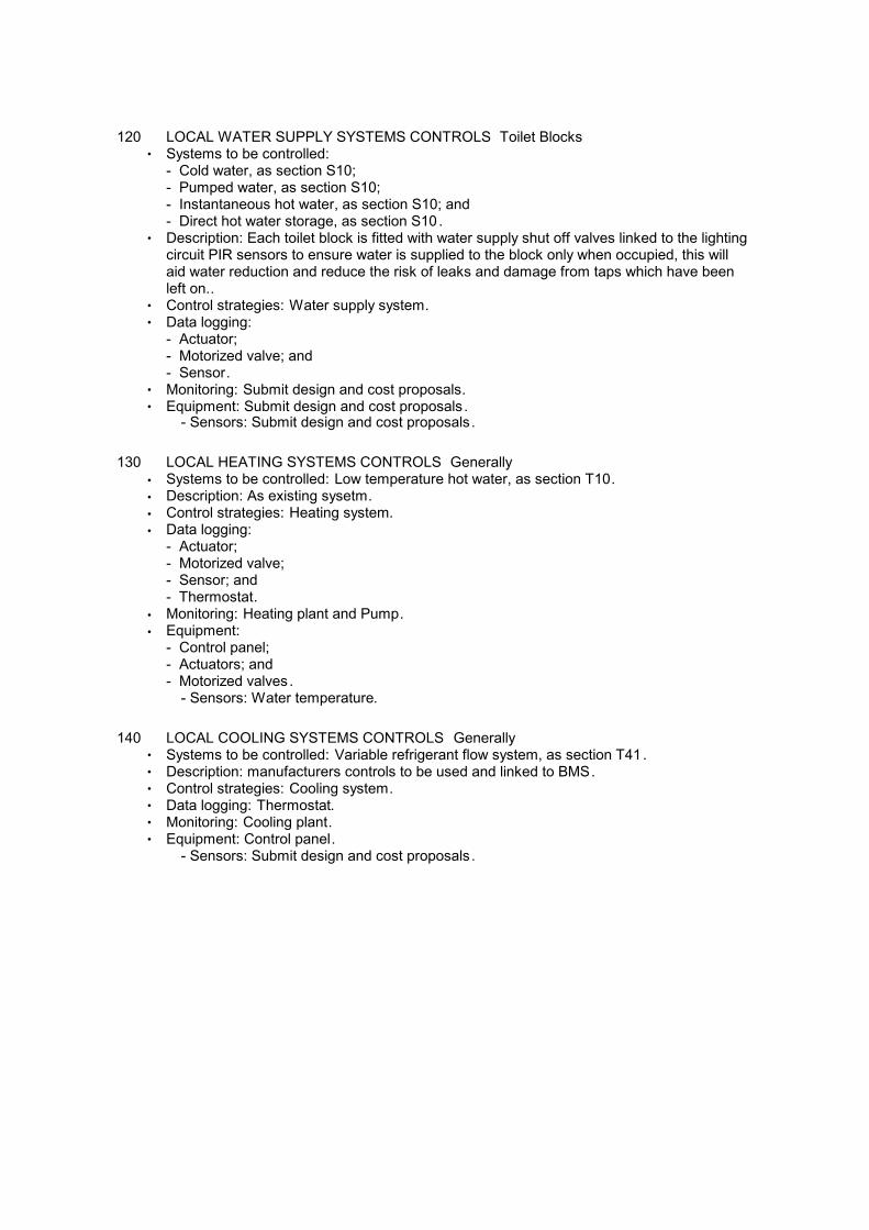
120 LOCAL WATER SUPPLY SYSTEMS CONTROLS Toilet Blocks• Systems to be controlled:
- Cold water, as section S10;- Pumped water, as section S10;- Instantaneous hot water, as section S10; and- Direct hot water storage, as section S10.
• Description: Each toilet block is fitted with water supply shut off valves linked to the lightingcircuit PIR sensors to ensure water is supplied to the block only when occupied, this willaid water reduction and reduce the risk of leaks and damage from taps which have beenleft on..
• Control strategies: Water supply system.• Data logging:
- Actuator;- Motorized valve; and- Sensor.
• Monitoring: Submit design and cost proposals.• Equipment: Submit design and cost proposals.
- Sensors: Submit design and cost proposals.
130 LOCAL HEATING SYSTEMS CONTROLS Generally
• Systems to be controlled: Low temperature hot water, as section T10.
• Description: As existing sysetm.
• Control strategies: Heating system.
• Data logging:- Actuator;- Motorized valve;- Sensor; and- Thermostat.
• Monitoring: Heating plant and Pump.
• Equipment:- Control panel;- Actuators; and- Motorized valves.
- Sensors: Water temperature.
140 LOCAL COOLING SYSTEMS CONTROLS Generally• Systems to be controlled: Variable refrigerant flow system, as section T41.• Description: manufacturers controls to be used and linked to BMS.• Control strategies: Cooling system.• Data logging: Thermostat.• Monitoring: Cooling plant.• Equipment: Control panel.
- Sensors: Submit design and cost proposals.

160 LOCAL AIR CONDITIONING SYSTEMS CONTROLS Offices• Systems to be controlled: Fan coil, as section U30.• Description: Local controls per fan coil and all linked to BMS.• Control strategies: Fan coil unit air conditioning system.• Data logging:
- Actuator;- Motorized valve;- Sensor; and- Thermostat.
• Monitoring:- Cooling plant;- Fan; and- Heating plant.
• Equipment: Control panel and Actuators.- Sensors: Air temperature.
170 ELECTRICAL CONNECTIONS Generally to all plant
• Power supplies to plant and equipment: as electrical Engineers design.
175 ELECTRICAL CONNECTIONS BETWEEN CONTROL DEVICES AND PLANT ANDEQUIPMENT Generally
• Equipment interconnectivity: Wired.
• Electrical connection cable: As Specialist's recommendations.- Containment: as electrical Engineers designs.
• Rewireable installations: as electrical Engineers design.
• Concealed installations: as electrical Engineers design.
SYSTEM PERFORMANCE
210 DESIGN
• Design: Complete the design of the mechanical engineering services controls andmonitoring system.
• Proposals: Submit mode of operation statements, point schedules, control logic diagrams,network topology schematics, panel diagrams and fascia drawings, method statements for testing and commissioning, method statements for witness testing and graphics.
215 WATER SUPPLY SYSTEMS CONTROL STRATEGY LOCAL WATER SUPPLY SYSTEMCONTROLS
• Start and stop control: Submit proposals.• Pressurization control strategies: Submit proposals.• Distribution control strategies: Submit proposals.• Pumps control strategies: Submit proposals.• Control points schedules: General .
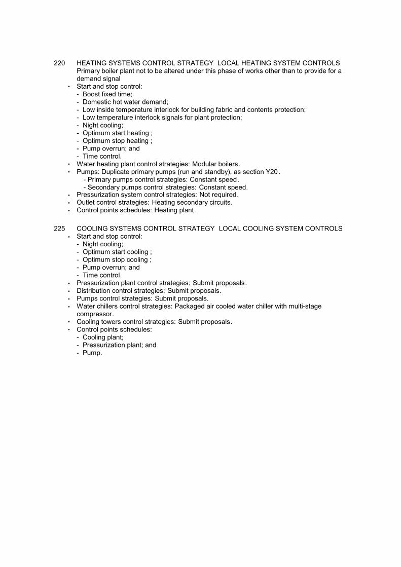
220 HEATING SYSTEMS CONTROL STRATEGY LOCAL HEATING SYSTEM CONTROLSPrimary boiler plant not to be altered under this phase of works other than to provide for ademand signal
• Start and stop control:- Boost fixed time;- Domestic hot water demand;- Low inside temperature interlock for building fabric and contents protection;- Low temperature interlock signals for plant protection;- Night cooling;- Optimum start heating ;- Optimum stop heating ;- Pump overrun; and- Time control.
• Water heating plant control strategies: Modular boilers.• Pumps: Duplicate primary pumps (run and standby), as section Y20 .
- Primary pumps control strategies: Constant speed.- Secondary pumps control strategies: Constant speed.
• Pressurization system control strategies: Not required.
• Outlet control strategies: Heating secondary circuits.
• Control points schedules: Heating plant.
225 COOLING SYSTEMS CONTROL STRATEGY LOCAL COOLING SYSTEM CONTROLS
• Start and stop control:- Night cooling;- Optimum start cooling ;- Optimum stop cooling ;- Pump overrun; and- Time control.
• Pressurization plant control strategies: Submit proposals.
• Distribution control strategies: Submit proposals.
• Pumps control strategies: Submit proposals.
• Water chillers control strategies: Packaged air cooled water chiller with multi-stagecompressor.
• Cooling towers control strategies: Submit proposals.• Control points schedules:
- Cooling plant;- Pressurization plant; and- Pump.

240 MECHANICAL VENTILATION SYSTEMS CONTROL STRATEGY CENTRAL CONTROLSYSTEM
• Start and stop control:- Fan overrun;- Low inside temperature interlock for building fabric and contents ;- Low temperature interlock signals for plant protection;- Night cooling;- Optimum start heating ;- Optimum stop heating ; and- Time control.
• Damper control strategies: Mixing.• Heating coils control strategies: Low temperature hot water pre-heat coil and frost
protection and Low temperature hot water heating coil .• Heat recovery devices control strategies: Fixed plate heat exchanger.• Supply fan control strategies: as existing.• Extract fan control strategies: as existing.• Terminal units control strategies: Submit proposals.• Filter control strategies: Submit proposals.
• Supply air temperature control strategies: Zone air temperature control.
• Control points schedules:- Air temperature ;- Fan; and- Heating coil.
242 MECHANICAL EXTRACT SYSTEMS CONTROL STRATEGY LOCAL VENTILATIONSYSTEM CONTROLS
• Start and stop control: Time control.
• Extract fan control strategies: Submit proposals.
• Control points schedules: Air temperature and Fan.
245 CONSTANT VOLUME AIR CONDITIONING SYSTEM CONTROL STRATEGY CENTRALCONTROL SYSTEM
• Start and stop control:- Low inside temperature interlock for building fabric and contents protection;- Low temperature interlock signals for plant protection;- Night cooling;- Optimum start cooling ;- Optimum stop cooling ;- Optimum start heating ;- Optimum stop heating ; and- Time control.
• Damper control strategies: Submit proposals.• Heating coils control strategies: Submit proposals.• Heat recovery devices control strategies: Fixed plate heat exchanger.• Cooling coil control strategies: Chilled water .• Dehumidification control strategies: Submit proposals.• Supply fan control strategies: Submit proposals.• Humidifier control strategies: Submit proposals.• Extract fan control strategies: Submit proposals.• Terminal units control strategies: Submit proposals.
• Filter control strategies: Submit proposals.
• Supply air temperature control strategies: Zone air temperature control.
• Control points schedules: General .
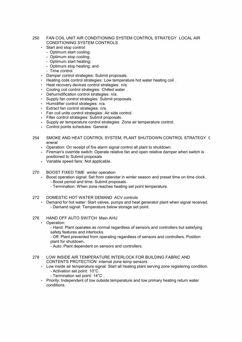
250 FAN COIL UNIT AIR CONDITIONING SYSTEM CONTROL STRATEGY LOCAL AIRCONDITIONING SYSTEM CONTROLS
• Start and stop control:- Optimum start cooling;- Optimum stop cooling;- Optimum start heating;- Optimum stop heating; and- Time control.
• Damper control strategies: Submit proposals.• Heating coils control strategies: Low temperature hot water heating coil .• Heat recovery devices control strategies: n/a.• Cooling coil control strategies: Chilled water .• Dehumidification control strategies: n/a.• Supply fan control strategies: Submit proposals.• Humidifier control strategies: n/a.• Extract fan control strategies: n/a.• Fan coil units control strategies: Air side control.• Filter control strategies: Submit proposals.
• Supply air temperature control strategies: Zone air temperature control.
• Control points schedules: General .
254 SMOKE AND HEAT CONTROL SYSTEM, PLANT SHUTDOWN CONTROL STRATEGY General
• Operation: On receipt of fire alarm signal control all plant to shutdown.
• Fireman's override switch: Operate relative fan and open relative damper when switch ispositioned to Submit proposals
• Variable speed fans: Not applicable.
270 BOOST FIXED TIME winter operation
• Boost operation signal: Set from calendar in winter season and preset time on time clock.- Boost period and time: Submit proposals.- Termination: When zone reaches heating set point temperature.
272 DOMESTIC HOT WATER DEMAND ACV controls• Demand for hot water: Start valves, pumps and heat generator plant when signal received.
- Demand signal: Temperature below storage set point.
276 HAND OFF AUTO SWITCH Main AHU• Operation:
- Hand: Plant operates as normal regardless of sensors and controllers but satisfyingsafety features and interlocks.- Off: Plant prevented from operating regardless of sensors and controllers. Positionplant for shutdown.- Auto: Plant dependent on sensors and controllers.
278 LOW INSIDE AIR TEMPERATURE INTERLOCK FOR BUILDING FABRIC ANDCONTENTS PROTECTION internal zone temp sensors
• Low inside air temperature signal: Start all heating plant serving zone registering condition.- Activation set point: 10°C.- Termination set point: 14°C .
• Priority: Independent of low outside temperature and low primary heating return water conditions.

280 LOW TEMPERATURE INTERLOCK SIGNALS FOR PLANT PROTECTION Frostprotection for plant
• Low outside air temperature condition: When activated start duty primary and secondarycircuit heating and cooling pumps. Open primary and secondary heating circuit valves toallow water to circulate through circuits unless plant is in operating mode.
- Activation set point: Below 3°C.- Termination set point: Activation set point plus 2°C.
• Low primary heating return water temperature condition: When activated start heat sourceand primary and secondary heating pumps if not already enabled.
- Activation set point: Below 8°C.- Termination set point: 55°C where non-condensing boilers are used.
282 NIGHT COOLING to office spaces• Type: Mechanical.• Activation: Submit proposals.
- Period of operation: Submit proposals.- Availability: Throughout entire non-occupied period.
• Wind speed limit: Shut down passive night cooling when wind speed exceeds: Submitproposals.
• Rain sensor: Shut inlet and outlet vents when rain is detected.
284 OPTIMUM START COOLING office areas
• Optimum start time: Use a self-adaptive control algorithm to calculate when to start plantoutside of normal operation by measuring outside and internal zone air temperature andusing thermal response of structure and plant. Operate plant at maximum output. Takeaccount of day of week and holidays. Following learning period, achieve temperature setpoint within +/- 15 minutes of start of occupancy.
- Zone cooling set point: 24°C.- Maximum precool time: 2h.
• Air handling plant start: Use separate control for each air handling plant. Start air handlingplant and cooling system.
286 OPTIMUM STOP COOLING office areas• Optimum stop time: Use a self-adaptive algorithm to calculate the earliest time prior to end
of occupancy when plant can be shutdown. Disable normal plant operation signal. Takeaccount of day of week and holidays. Following learning period, achieve maximumtemperature within +/- 15 minutes of end of occupancy.
- Maximum acceptable temperature during occupied period: 26°C.- Maximum period between stop and end of occupied period: 2 h.
288 OPTIMUM START HEATING office areas• Optimum start time: Use a self-adaptive control algorithm to calculate when to start plant
outside of normal operation by measuring outside and internal zone air temperature andusing thermal response of structure and plant. Operate plant at maximum output. Takeaccount of day of week and holidays. Following learning period, achieve temperature setpoint within +/- 15 minutes of start of occupancy.
- Zone heating set point: 19°C.- Maximum preheat time: 4 h.
• Air handling plant start: Use separate control for each air handling plant. Start air handlingplant and boiler heating system.

290 OPTIMUM STOP HEATING office areas• Optimum stop time: Use a self-adaptive algorithm to calculate the earliest time prior to end
of occupancy when plant can be shutdown. Disable normal plant operation signal. Takeaccount of day of week and holidays. Following learning period, achieve minimumtemperature within +/- 15 minutes of end of occupancy.
- Minimum acceptable temperature during occupied period: 18°C.- Maximum period between stop and end of occupied period: 2 h.
294 TIME CONTROL generally• Time clock: Provide clock and calendar programmed with periods of normal operation.
Automatically change between GMT and British summer time and allow for leap years.• Extension of plant operation: Allow manual override, for normal operation, activated by
push button switch.- Period: 1 hr.
• Winter mode: Between 1 October and 30 April .- Outside temperature: Above 17°C for at least 30 minutes.
PRODUCTS
324 DOMESTIC HOT WATER NON-STORAGE CALORIFIER CONTROL STRATEGY ACV units in plantroom
• Medium: Water, using three port diverting valve and isolating valve .
• Non-operation: Open bypass port of control valve, close isolating valve and disablesecondary pump.
• Operation: When demand is signalled, operate secondary pump, open isolating valve andmodulate control valve to maintain secondary flow temperature at set point.
- Set point: 60°C.
• Alarm: Raise an alarm when domestic hot water secondary flow water temperature fallsbelow specified temperature during operating period.
- Specified temperature: 50°C.
• High limit thermostat: When calorifier water temperature is above the high temperature setpoint, close the control valve and shut isolating valve. Start secondary pump overrun.Raise alarm.
- Set point: 90°C.- Overrun period: 5 minutes.
• Secondary circuit pump failure: Set control valve to bypass and shut isolating valve.• Stratification pump: part of ACV units.
329 VARIABLE SPEED PUMPS CONTROL STRATEGY DHW circulation• Function: primary.• Plant shut down: Turn pumps off and fully close valves serving loads closed.
- Long shutdown period: Run pumps for 5 minutes on a daily basis when shut down islonger than 2 days.
• Operation: Run pumps on receipt of signal. Modulate pumps to obtain design differentialset point between flow and return circuits, across the load at furthest point or according tohe lowest negative deviation from the differential set point.
- Differential set point: Submit proposals.• Shared duty: Operate pumps together at same speed. If one pump fails increase the speed
of the other pump to meet the load and raise an alarm.
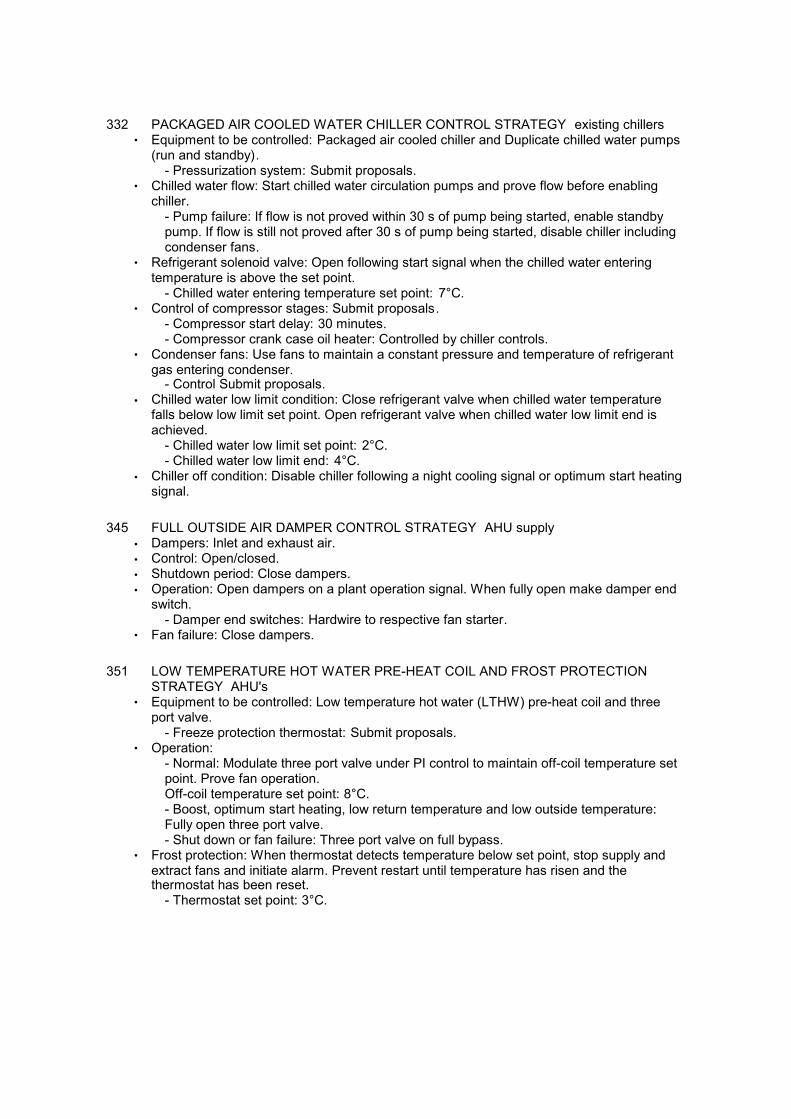
332 PACKAGED AIR COOLED WATER CHILLER CONTROL STRATEGY existing chillers• Equipment to be controlled: Packaged air cooled chiller and Duplicate chilled water pumps
(run and standby).- Pressurization system: Submit proposals.
• Chilled water flow: Start chilled water circulation pumps and prove flow before enablingchiller.
- Pump failure: If flow is not proved within 30 s of pump being started, enable standbypump. If flow is still not proved after 30 s of pump being started, disable chiller includingcondenser fans.
• Refrigerant solenoid valve: Open following start signal when the chilled water enteringtemperature is above the set point.
- Chilled water entering temperature set point: 7°C.• Control of compressor stages: Submit proposals.
- Compressor start delay: 30 minutes.- Compressor crank case oil heater: Controlled by chiller controls.
• Condenser fans: Use fans to maintain a constant pressure and temperature of refrigerantgas entering condenser.
- Control Submit proposals.
• Chilled water low limit condition: Close refrigerant valve when chilled water temperaturefalls below low limit set point. Open refrigerant valve when chilled water low limit end isachieved.
- Chilled water low limit set point: 2°C.- Chilled water low limit end: 4°C.
• Chiller off condition: Disable chiller following a night cooling signal or optimum start heatingsignal.
345 FULL OUTSIDE AIR DAMPER CONTROL STRATEGY AHU supply
• Dampers: Inlet and exhaust air.
• Control: Open/closed.
• Shutdown period: Close dampers.
• Operation: Open dampers on a plant operation signal. When fully open make damper endswitch.
- Damper end switches: Hardwire to respective fan starter.• Fan failure: Close dampers.
351 LOW TEMPERATURE HOT WATER PRE-HEAT COIL AND FROST PROTECTIONSTRATEGY AHU's
• Equipment to be controlled: Low temperature hot water (LTHW) pre-heat coil and threeport valve.
- Freeze protection thermostat: Submit proposals.• Operation:
- Normal: Modulate three port valve under PI control to maintain off-coil temperature setpoint. Prove fan operation.Off-coil temperature set point: 8°C.- Boost, optimum start heating, low return temperature and low outside temperature:Fully open three port valve.- Shut down or fan failure: Three port valve on full bypass.
• Frost protection: When thermostat detects temperature below set point, stop supply andextract fans and initiate alarm. Prevent restart until temperature has risen and thethermostat has been reset.
- Thermostat set point: 3°C.
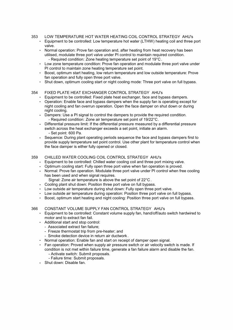
353 LOW TEMPERATURE HOT WATER HEATING COIL CONTROL STRATEGY AHU's• Equipment to be controlled: Low temperature hot water (LTHW) heating coil and three port
valve.• Normal operation: Prove fan operation and, after heating from heat recovery has been
utilised, modulate three port valve under PI control to maintain required condition.- Required condition: Zone heating temperature set point of 19°C.
• Low zone temperature condition: Prove fan operation and modulate three port valve under PI control to maintain zone heating temperature set point.
• Boost, optimum start heating, low return temperature and low outside temperature: Provefan operation and fully open three port valve.
• Shut down, optimum cooling start or night cooling mode: Three port valve on full bypass.
354 FIXED PLATE HEAT EXCHANGER CONTROL STRATEGY AHU's• Equipment to be controlled: Fixed plate heat exchanger, face and bypass dampers.• Operation: Enable face and bypass dampers when the supply fan is operating except for
night cooling and fan overrun operation. Open the face damper on shut down or duringnight cooling.
• Dampers: Use a PI signal to control the dampers to provide the required condition.- Required condition: Zone air temperature set point of 19/22°C.
• Differential pressure limit: If the differential pressure measured by a differential pressureswitch across the heat exchanger exceeds a set point, initiate an alarm.
- Set point: 600 Pa.
• Sequence: During plant operating periods sequence the face and bypass dampers first toprovide supply temperature set point control. Use other plant for temperature control whenthe face damper is either fully opened or closed.
359 CHILLED WATER COOLING COIL CONTROL STRATEGY AHU's
• Equipment to be controlled: Chilled water cooling coil and three port mixing valve.
• Optimum cooling start: Fully open three port valve when fan operation is proved.
• Normal: Prove fan operation. Modulate three port valve under PI control when free coolinghas been used and when signal requires.
Signal: Zone air temperature is above the set point of 22°C .
• Cooling plant shut down: Position three port valve on full bypass.• Low outside air temperature during shut down: Fully open three port valve.• Low outside air temperature during operation: Position three port valve on full bypass.• Boost, optimum start heating and night cooling: Position three port valve on full bypass.
366 CONSTANT VOLUME SUPPLY FAN CONTROL STRATEGY AHU's• Equipment to be controlled: Constant volume supply fan, hand/off/auto switch hardwired to
motor and to extract fan fail.• Additional start and stop control:
- Associated extract fan failure;- Freeze thermostat trip from pre-heater; and- Smoke detection device in return air ductwork .
• Normal operation: Enable fan and start on receipt of damper open signal.• Fan operation: Proved when supply air pressure switch or air velocity switch is made. If
condition is not met within failure time, generate a fan failure alarm and disable the fan.- Activate switch: Submit proposals.- Failure time: Submit proposals.
• Shut down: Disable fan.

375 CONSTANT VOLUME EXTRACT FAN CONTROL STRATEGY AHU's• Equipment to be controlled: Constant volume extract fan interlocked with associated supply
fan and hand/off/auto switch hardwired to motor.• Additional start and stop control:
- Associated supply fan failure;- Freeze thermostat trip from pre-heater; and- Smoke detection device in return air ductwork .
• Normal operation: Enable fan and start on receipt of damper open signal.• Fan operation: Proved when extract air pressure switch or air velocity switch is made. If
condition is not met within failure time, generate a fan failure alarm and disable the fan.- Activate switch: Submit proposals.- Failure time: Submit proposals.
• Shut down: Disable fan.
387 FAN COIL UNIT, AIR SIDE CONTROL STRATEGY Generally• Equipment to be controlled: Fan coil unit or group of fan coil units with fans, heating coils
and cooling coils.- Motor speed: as fan coil schedule.
• Start and stop control: BMS.
• Shut down: Submit proposals.
• Low outside temperature or low return water temperature condition: Open valves.
• Fan overrun operation: Close cooling valve, position dampers to supply air over heatingcoil.
- Heater: Submit proposals.- Fan: Submit proposals.
• Optimum start heating, boost or low zone temperature condition: Fully open heatingdamper and close cooling valve.
- Fan: Run.- Heater: Fully open the heating valve .
• Optimum start cooling: Fully open cooling damper and valve and disable heating.- Fan: Run.
• Night cooling: Close valves and disable heating, position dampers to supply air withoutpassing over cooling or heating coils.
- Fan: Run.• Normal operation: Modulate the dampers under PI control to provide the zone heating and
cooling temperature set points. The cooling damper operates in reverse to the heatingdamper.
- Heating set point: 19°C.- Cooling set point: 22°C.- Fan: Run.- Heater: Open the heating valves.

388 FAN COIL UNIT, WATER SIDE CONTROL STRATEGY Generally• Equipment to be controlled: Fan coil unit or group of fan coil units with fans, heating coils
and cooling coils.- Motor speed: Submit proposals.
• Shut down: Disable unit with fan switched off and valves closed.• Low outside temperature or low return water temperature condition: Open valves.• Fan overrun operation: Close cooling valve.
- Heater: Submit proposals.- Fan: Run fan.
• Optimum start heating, boost or low zone temperature condition: Close cooling valve.- Heater: Fully open heating valve .- Fan: Run.
• Optimum start cooling: Fully open cooling valve and disable heating.- Fan: Run.
• Night cooling: Close valves and disable heating.- Fan: Run.
• Normal operation: Modulate the heating and cooling valve positions under PI control toprovide the zone heating and cooling temperature set points.
- Heating set point: 19.- Cooling set point: 22°C.- Fan: Run.
390 AIR FILTER WITH PRESSURE SENSOR CONTROL STRATEGY AHU's
• Air filter: Monitor cleanliness by measuring differential pressure across filters usingsensors.
• Dirty filter warning signal: Submit proposals.
392 CONSTANT AIR VOLUME SYSTEM, ZONE TEMPERATURE CONTROL OF PRIMARYSUPPLY AIR TEMPERATURE CONTROL STRATEGY Genrally
• Shutdown: Supply air temperature control inactive.
• Optimum start, boost or night cooling: Supply air temperature control inactive.
• Normal operation or low zone temperature condition: Schedule the supply air temperaturelinearly in relation to the common return air temperature subject to upper and lower supplyair temperature set points.
- Maximum set point: 25°C when average zone temperature is at or below 19°C .- Minimum set point: 15°C when average zone temperature is at or above 24°C .- Zone reheaters: Not applicable.- Zone coolers: Not applicable.
• Sequence: Operate heat recovery devices before air heater coil and Use mixing dampersto provide free cooling before air cooling coil .
• High/low temperature warning: Generate a warning signal if supply air temperature risesabove high limit or drops below low limit.
- High limit: 30°C.- Low limit: 12°C.
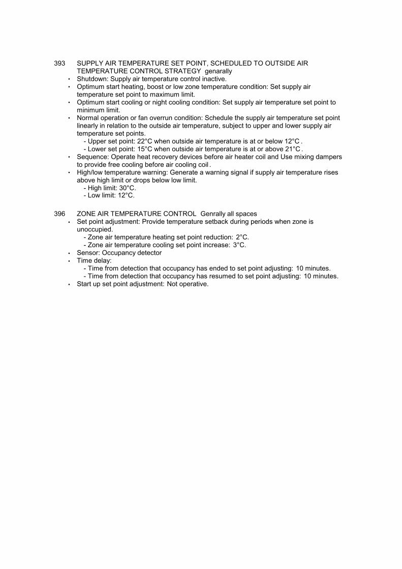
393 SUPPLY AIR TEMPERATURE SET POINT, SCHEDULED TO OUTSIDE AIRTEMPERATURE CONTROL STRATEGY genarally
• Shutdown: Supply air temperature control inactive.• Optimum start heating, boost or low zone temperature condition: Set supply air
temperature set point to maximum limit.• Optimum start cooling or night cooling condition: Set supply air temperature set point to
minimum limit.• Normal operation or fan overrun condition: Schedule the supply air temperature set point
linearly in relation to the outside air temperature, subject to upper and lower supply air temperature set points.
- Upper set point: 22°C when outside air temperature is at or below 12°C .- Lower set point: 15°C when outside air temperature is at or above 21°C .
• Sequence: Operate heat recovery devices before air heater coil and Use mixing dampersto provide free cooling before air cooling coil .
• High/low temperature warning: Generate a warning signal if supply air temperature risesabove high limit or drops below low limit.
- High limit: 30°C.- Low limit: 12°C.
396 ZONE AIR TEMPERATURE CONTROL Genrally all spaces
• Set point adjustment: Provide temperature setback during periods when zone isunoccupied.
- Zone air temperature heating set point reduction: 2°C.- Zone air temperature cooling set point increase: 3°C.
• Sensor: Occupancy detector
• Time delay:- Time from detection that occupancy has ended to set point adjusting: 10 minutes.- Time from detection that occupancy has resumed to set point adjusting: 10 minutes.
• Start up set point adjustment: Not operative.

510 CONTROL PANEL plantroom• Standards: To BS 7671, BS EN 60439-1 and -3.• Manufacturer: Contractor's choice.
- Product reference: Contractor's choice.• Assembly: Fully factory tested.
- Approval: ASTA certified.- Evidence of certification: Required.
• Internal separation: Form 4 to BS EN 60439-1 National Annex.• Voltage: contractors choice.• Phase: Three.• Enclosure:
- Standard: To BS EN 62208.- Ingress protection to BS EN 60529: Contractor's choice.- Material: Metal.- Finish: Powder coated.- Colour: Submit proposals.- Method of fixing: Wall mounting - surface.- Intended location: Indoor.- Mechanical protection to BS EN 62262: submit proposals.- Incoming cabling access: as existing.- Outgoing cabling access: as existing.
• Locking mechanism: Cylinder locks with a standard key type.
• Incoming device: Switch-disconnector to BS EN 60947-3.- Interlock: Cannot be opened except with the isolator in the off position.- Rating: Submit proposals.- Poles: Submit proposals.
• Outgoing devices: Submit proposals.
• Identification:- Cable terminations: Label with circuit reference, with push-on plastics markers.
• Full length internal earth bar: Required.- Size: Submit proposals.
• Internal busbars and wiring:- Type: PVC insulated.- Size (minimum): 1 mm².
• Internal wiring: Segregate power and signal cabling. Contain within slotted trunking.- Wiring capacity (maximum): 45% full by volume.
• Busbars and connections: Fully shrouded.• Accessories:
- Indicator lamps;- Padlock and key cabinet; and- Submit proposals.
525 INDICATOR LAMPS• Lamp type: Clustered LED with bezel. Standardize lamp type.• Lens colour: To BS EN 60073.• Lamp mounting: Recessed.• Common lamp test facility: Required.• Access for lamp replacement: Externally from enclosure front.
530 PADLOCKS AND KEYS
• Manufacturer: Contractor's choice.- Product reference: Contractor's choice.
• Locking mechanism: Contractor's choice.
• Material: Contractor's choice.
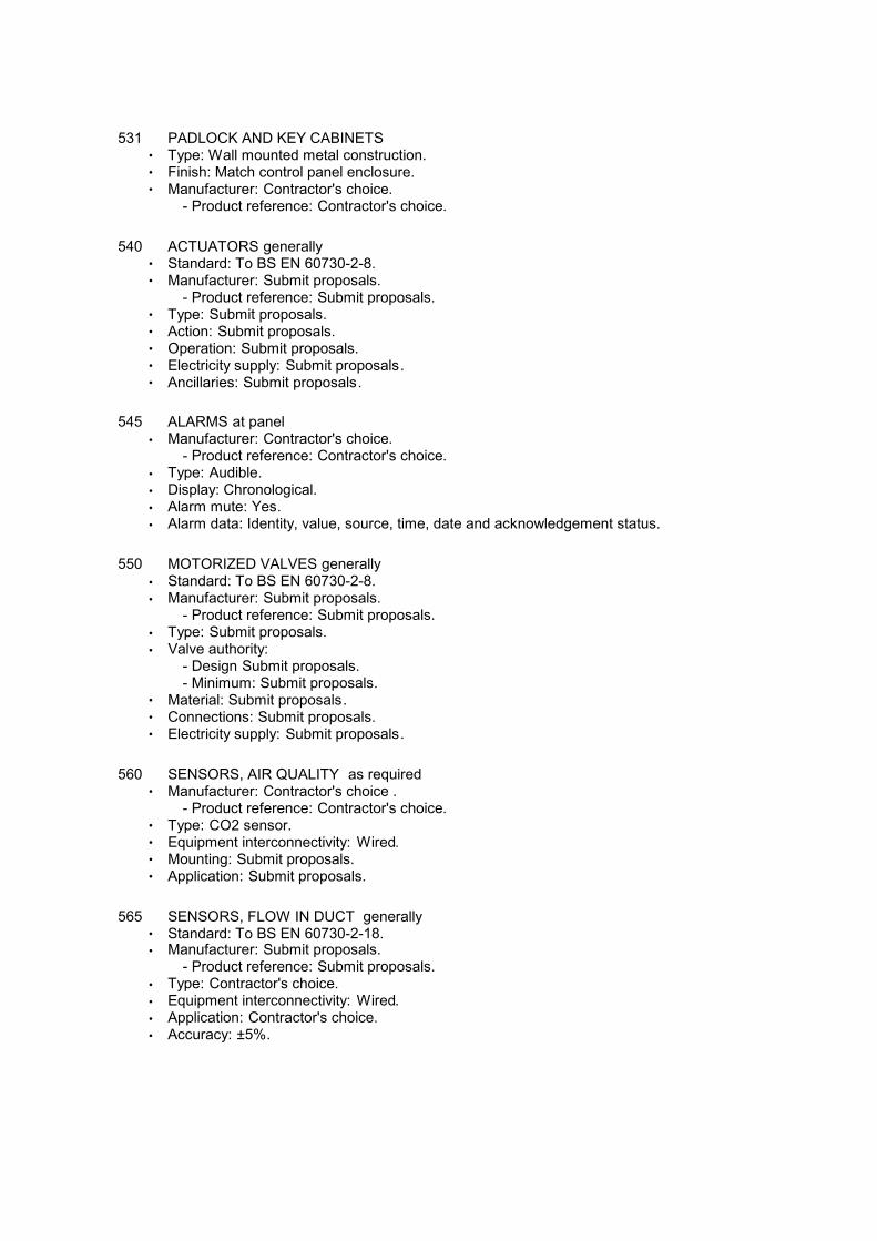
531 PADLOCK AND KEY CABINETS• Type: Wall mounted metal construction.• Finish: Match control panel enclosure.• Manufacturer: Contractor's choice.
- Product reference: Contractor's choice.
540 ACTUATORS generally• Standard: To BS EN 60730-2-8.• Manufacturer: Submit proposals.
- Product reference: Submit proposals.• Type: Submit proposals.• Action: Submit proposals.• Operation: Submit proposals.• Electricity supply: Submit proposals.• Ancillaries: Submit proposals.
545 ALARMS at panel
• Manufacturer: Contractor's choice.- Product reference: Contractor's choice.
• Type: Audible.
• Display: Chronological.
• Alarm mute: Yes.
• Alarm data: Identity, value, source, time, date and acknowledgement status.
550 MOTORIZED VALVES generally
• Standard: To BS EN 60730-2-8.
• Manufacturer: Submit proposals.- Product reference: Submit proposals.
• Type: Submit proposals.
• Valve authority: - Design Submit proposals.- Minimum: Submit proposals.
• Material: Submit proposals.• Connections: Submit proposals.• Electricity supply: Submit proposals.
560 SENSORS, AIR QUALITY as required• Manufacturer: Contractor's choice .
- Product reference: Contractor's choice.• Type: CO2 sensor.• Equipment interconnectivity: Wired.• Mounting: Submit proposals.• Application: Submit proposals.
565 SENSORS, FLOW IN DUCT generally• Standard: To BS EN 60730-2-18.• Manufacturer: Submit proposals.
- Product reference: Submit proposals.
• Type: Contractor's choice.
• Equipment interconnectivity: Wired.
• Application: Contractor's choice.
• Accuracy: ±5%.
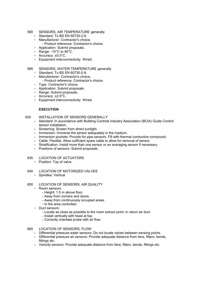
580 SENSORS, AIR TEMPERATURE generally• Standard: To BS EN 60730-2-9.• Manufacturer: Contractor's choice.
- Product reference: Contractor's choice.• Application: Submit proposals.• Range: -10°C to 40°C.• Accuracy: ±0.5°C.• Equipment interconnectivity: Wired.
585 SENSORS, WATER TEMPERATURE generally• Standard: To BS EN 60730-2-9.• Manufacturer: Contractor's choice.
- Product reference: Contractor's choice.• Type: Contractor's choice.• Application: Submit proposals.• Range: Submit proposals.• Accuracy: ±2.0°C.
• Equipment interconnectivity: Wired.
EXECUTION
620 INSTALLATION OF SENSORS GENERALLY
• Standard: In accordance with Building Controls Industry Association (BCIA) Guide Controlsensor installation.
• Screening: Screen from direct sunlight.
• Immersion: Immerse the sensor adequately in the medium.
• Immersion pockets: Provide for pipe sensors. Fill with thermal conductive compound.
• Cable: Flexible. Allow sufficient spare cable to allow for removal of sensor.
• Stratification: Install more than one sensor or an averaging sensor if necessary.
• Positions of sensors: Submit proposals.
630 LOCATION OF ACTUATORS• Position: Top of valve.
640 LOCATION OF MOTORIZED VALVES• Spindles: Vertical.
650 LOCATION OF SENSORS, AIR QUALITY• Room sensors:
- Height: 1.5 m above floor.- Away from corners and doors.- Away from continuously occupied areas.- In the area controlled.
• Duct sensors:- Locate as close as possible to the room extract point, in return air duct.- Install vertically with head at top.- Correctly orientate probe with air flow.
660 LOCATION OF SENSORS, FLOW
• Differential pressure water sensors: Do not locate valves between sensing points.
• Differential pressure air sensors: Provide adequate distance from fans, filters, bends,fittings etc.
• Velocity sensors: Provide adequate distance from fans, filters, bends, fittings etc.
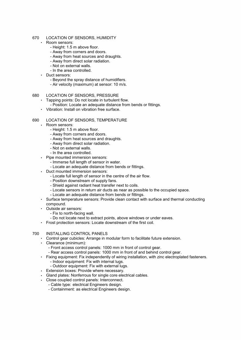
670 LOCATION OF SENSORS, HUMIDITY• Room sensors:
- Height: 1.5 m above floor.- Away from corners and doors.- Away from heat sources and draughts.- Away from direct solar radiation.- Not on external walls.- In the area controlled.
• Duct sensors:- Beyond the spray distance of humidifiers.- Air velocity (maximum) at sensor: 10 m/s.
680 LOCATION OF SENSORS, PRESSURE• Tapping points: Do not locate in turbulent flow.
- Position: Locate an adequate distance from bends or fittings.• Vibration: Install on vibration free surface.
690 LOCATION OF SENSORS, TEMPERATURE
• Room sensors:- Height: 1.5 m above floor.- Away from corners and doors.- Away from heat sources and draughts.- Away from direct solar radiation.- Not on external walls.- In the area controlled.
• Pipe mounted immersion sensors:- Immerse full length of sensor in water.- Locate an adequate distance from bends or fittings.
• Duct mounted immersion sensors:- Locate full length of sensor in the centre of the air flow.- Position downstream of supply fans.- Shield against radiant heat transfer next to coils.- Locate sensors in return air ducts as near as possible to the occupied space.- Locate an adequate distance from bends or fittings.
• Surface temperature sensors: Provide clean contact with surface and thermal conductingcompound.
• Outside air sensors:- Fix to north-facing wall.- Do not locate next to extract points, above windows or under eaves.
• Frost protection sensors: Locate downstream of the first coil.
700 INSTALLING CONTROL PANELS• Control gear cubicles: Arrange in modular form to facilitate future extension.• Clearance (minimum):
- Front access control panels: 1000 mm in front of control gear.- Rear access control panels: 1000 mm in front of and behind control gear.
• Fixing equipment: Fix independently of wiring installation, with zinc electroplated fasteners.- Indoor equipment: Fix with internal lugs.- Outdoor equipment: Fix with external lugs.
• Extension boxes: Provide where necessary.
• Gland plates: Nonferrous for single core electrical cables.
• Close coupled control panels: Interconnect.- Cable type: electrical Engineers design.- Containment: as electrical Engineers design.
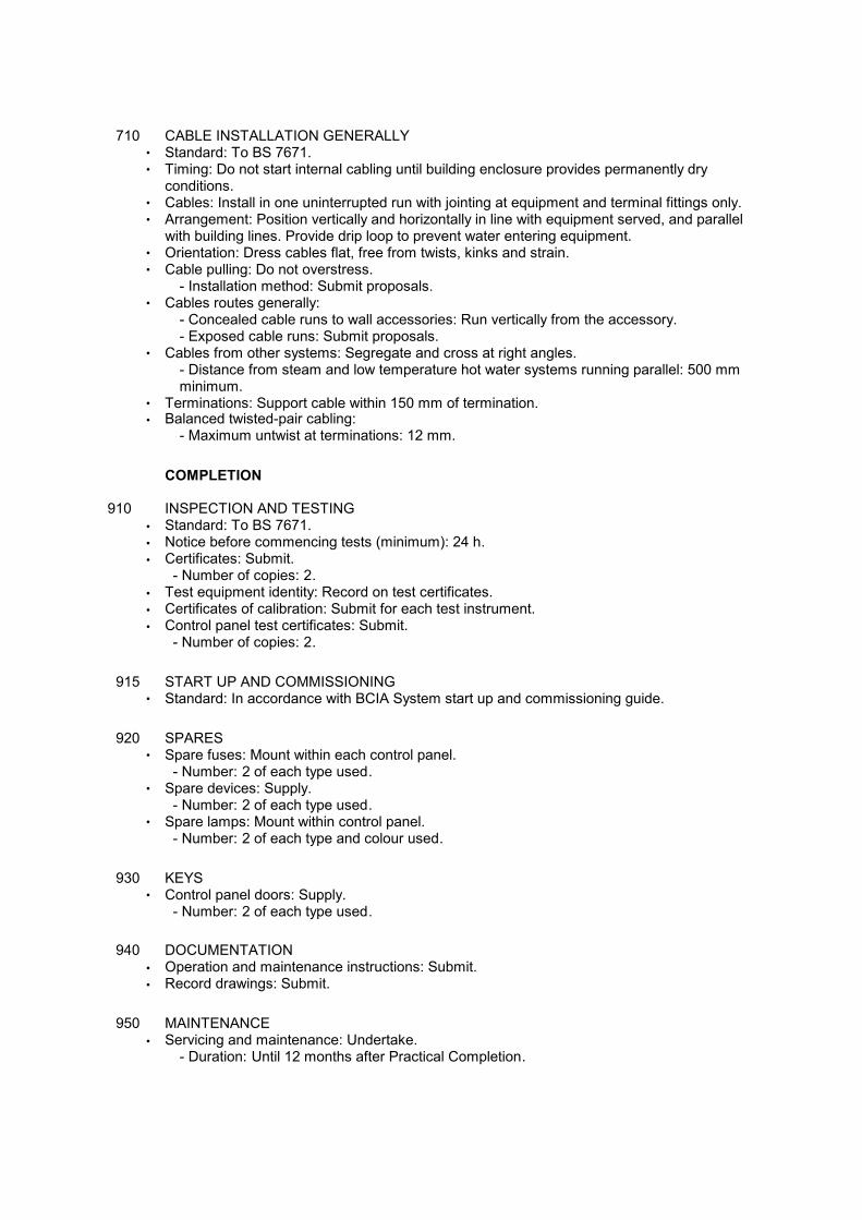
710 CABLE INSTALLATION GENERALLY• Standard: To BS 7671.• Timing: Do not start internal cabling until building enclosure provides permanently dry
conditions.• Cables: Install in one uninterrupted run with jointing at equipment and terminal fittings only.• Arrangement: Position vertically and horizontally in line with equipment served, and parallel
with building lines. Provide drip loop to prevent water entering equipment. • Orientation: Dress cables flat, free from twists, kinks and strain.• Cable pulling: Do not overstress.
- Installation method: Submit proposals.• Cables routes generally:
- Concealed cable runs to wall accessories: Run vertically from the accessory.- Exposed cable runs: Submit proposals.
• Cables from other systems: Segregate and cross at right angles.- Distance from steam and low temperature hot water systems running parallel: 500 mmminimum.
• Terminations: Support cable within 150 mm of termination.• Balanced twisted-pair cabling:
- Maximum untwist at terminations: 12 mm.
COMPLETION
910 INSPECTION AND TESTING
• Standard: To BS 7671.
• Notice before commencing tests (minimum): 24 h.
• Certificates: Submit.- Number of copies: 2.
• Test equipment identity: Record on test certificates.
• Certificates of calibration: Submit for each test instrument.
• Control panel test certificates: Submit.- Number of copies: 2.
915 START UP AND COMMISSIONING• Standard: In accordance with BCIA System start up and commissioning guide.
920 SPARES• Spare fuses: Mount within each control panel.
- Number: 2 of each type used.• Spare devices: Supply.
- Number: 2 of each type used.• Spare lamps: Mount within control panel.
- Number: 2 of each type and colour used.
930 KEYS• Control panel doors: Supply.
- Number: 2 of each type used.
940 DOCUMENTATION
• Operation and maintenance instructions: Submit.
• Record drawings: Submit.
950 MAINTENANCE
• Servicing and maintenance: Undertake.- Duration: Until 12 months after Practical Completion.

Y50
Mechanical commissioning
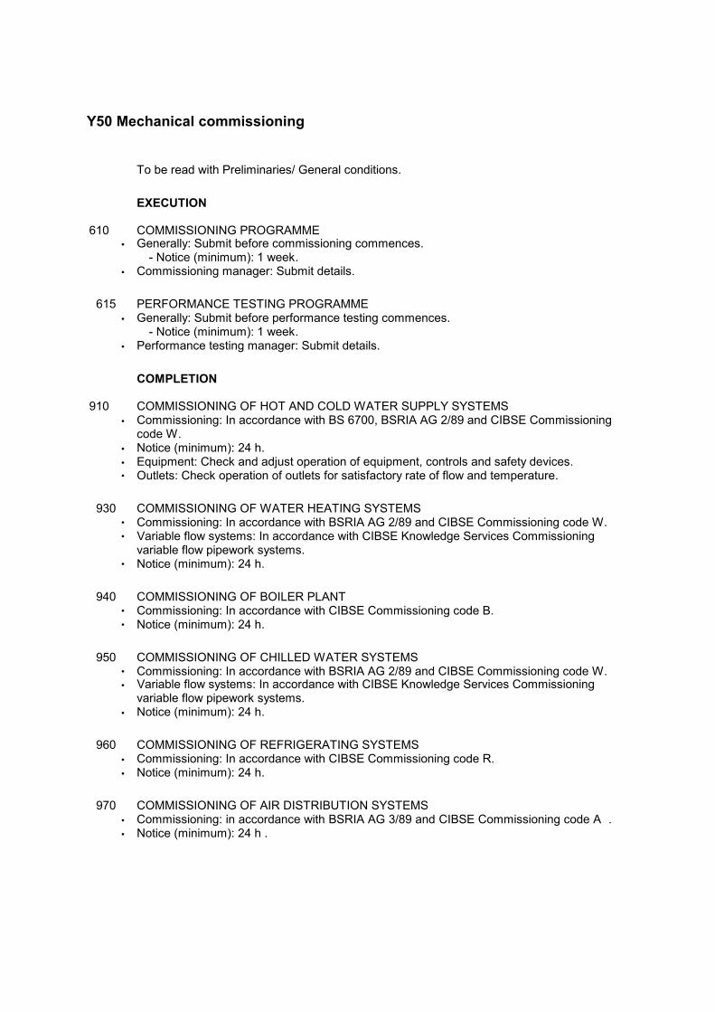
Y50 Mechanical commissioning
To be read with Preliminaries/ General conditions.
EXECUTION
610 COMMISSIONING PROGRAMME• Generally: Submit before commissioning commences.
- Notice (minimum): 1 week.
• Commissioning manager: Submit details.
615 PERFORMANCE TESTING PROGRAMME
• Generally: Submit before performance testing commences.- Notice (minimum): 1 week.
• Performance testing manager: Submit details.
COMPLETION
910 COMMISSIONING OF HOT AND COLD WATER SUPPLY SYSTEMS
• Commissioning: In accordance with BS 6700, BSRIA AG 2/89 and CIBSE Commissioningcode W.
• Notice (minimum): 24 h.
• Equipment: Check and adjust operation of equipment, controls and safety devices.• Outlets: Check operation of outlets for satisfactory rate of flow and temperature.
930 COMMISSIONING OF WATER HEATING SYSTEMS• Commissioning: In accordance with BSRIA AG 2/89 and CIBSE Commissioning code W.• Variable flow systems: In accordance with CIBSE Knowledge Services Commissioning
variable flow pipework systems.• Notice (minimum): 24 h.
940 COMMISSIONING OF BOILER PLANT• Commissioning: In accordance with CIBSE Commissioning code B.• Notice (minimum): 24 h.
950 COMMISSIONING OF CHILLED WATER SYSTEMS• Commissioning: In accordance with BSRIA AG 2/89 and CIBSE Commissioning code W.• Variable flow systems: In accordance with CIBSE Knowledge Services Commissioning
variable flow pipework systems.
• Notice (minimum): 24 h.
960 COMMISSIONING OF REFRIGERATING SYSTEMS
• Commissioning: In accordance with CIBSE Commissioning code R.
• Notice (minimum): 24 h.
970 COMMISSIONING OF AIR DISTRIBUTION SYSTEMS
• Commissioning: in accordance with BSRIA AG 3/89 and CIBSE Commissioning code A .
• Notice (minimum): 24 h .
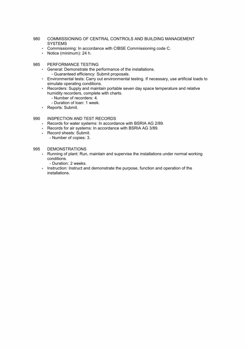
980 COMMISSIONING OF CENTRAL CONTROLS AND BUILDING MANAGEMENTSYSTEMS
• Commissioning: In accordance with CIBSE Commissioning code C.• Notice (minimum): 24 h.
985 PERFORMANCE TESTING• General: Demonstrate the performance of the installations.
- Guaranteed efficiency: Submit proposals.• Environmental tests: Carry out environmental testing. If necessary, use artificial loads to
simulate operating conditions.• Recorders: Supply and maintain portable seven day space temperature and relative
humidity recorders, complete with charts.- Number of recorders: 4.- Duration of loan: 1 week.
• Reports: Submit.
990 INSPECTION AND TEST RECORDS
• Records for water systems: In accordance with BSRIA AG 2/89.
• Records for air systems: In accordance with BSRIA AG 3/89.
• Record sheets: Submit.- Number of copies: 3.
995 DEMONSTRATIONS
• Running of plant: Run, maintain and supervise the installations under normal workingconditions.- Duration: 2 weeks.
• Instruction: Instruct and demonstrate the purpose, function and operation of theinstallations.