ballistic resistance of the transport airplane …€¦ · ballistic resistance of the transport...
TRANSCRIPT

20th SVSFEM ANSYS Users' Group Meeting and Conference 2012 SVSFEM s.r.o
http://aum.svsfem.cz 1
BALLISTIC RESISTANCE OF THE TRANSPORT AIRPLANE FUSELAGE TO IMPACT
OF 9 MM ACTION 5 PISTOL BULLET
JURAJ HUB1, JAN KOMENDA2
1University of Defence, Department of Aircraft and Rocket Technologies 2University of Defence, Department of Weapons and Ammunition
Abstract: The article presents an experimental and numerical approach to estimate ballistic limits of the pistol hollow point bullet Action 5 penetrating the target representing the transport airplane fuselage. The target containing the composite sidewall, the insulation glass wool layer and the duralumin skin plate is penetrated in two ways – directly and using forward obstacle in form of substitute biological material (ballistic gel) to achieve the conditions of firing on-board. Expansion ability of the bullet Action 5 causes a different effect on the target in case of perforation of the substitute material first. The simulation using Finite Element Method system Ansys Autodyn v.14 presents 2D model based on experimental shooting. The simulation introduces the estimation of the substitute material thickness to achieve the ballistic limit for particular parts of the target.
Keywords: Action 5, hollow point bullet, ballistic limit, aircraft fuselage, FEM
1 Introduction
Rating the ballistic resistance of airliner airframe in case of firing on-board is important to assess the behavior of the aircraft structure in order to avoid catastrophic consequences. Shooting on-board occur in case of service procedure done by armed escort, which is usually armed with a gun and expansion ammunition.
Conditions of bullet fired on-board and penetrating the plane’s fuselage can be very diverse. If the standard pistol bullet strikes the fuselage wall directly at angles close to the value of 90° without any forward obstacle, a smooth penetration occurs with the surplus of energy with high velocity of the range 300 m/s to 400 m/s. Such penetration has no significant effect on the functionality of the fuselage as the pressurized vessel.
However, if the bullet penetrates another target before impacting of the fuselage, e. g. human body, which is the primary target and the fuselage is the secondary target, the effect of the bullet may be radically different with unfavorable consequences. Such a bullet is not only reduced in velocity, but also usually a large deformation occurs, so called expansion. If the loss of energy of the bullet is higher, the perforation of the fuselage is not performed or finished. The deformed bullet with higher impact energy may cause more serious damage of the outer duralumin fuselage skin in conditions close to the limit velocity in the region of low bullet velocity of 100 m/s to 200 m/s. The damage in those conditions could be more serious and can cause an irregular hole after perforating the skin with the potential for the propagation of fatigue cracks, which is not favorable. However, it is supposed, that this kind of damage is dangerous in terms of longer aircraft operation than the time needed to complete the flight.
1.1 Action 5 ammunition characteristics
Ballistic resistance analysis made in this article is related to the service cartridge Action 5. It is a cartridge of caliber 9 mm Luger with homogeneous brass bullet with front expansion cavity covered with plastic cap, see Image 1. Basic ballistic characteristics of the cartridge important for the target effecting, are shown in Table 1.

20th SVSFEM ANSYS Users' Group Meeting and Conference 2012 SVSFEM s.r.o
http://aum.svsfem.cz 2
Image 1 – The cartridge Action 5 and its parts – from the left the cartridge Action 5, two times the bullet of caliber 9 mm, the cartridge case with primer, the cut view of the whole cartridge Action 5
Table 1 Ballistic characteristics of the cartridge Action 5
Weight of the bullet mb [g] 6.1 Initial bullet velocity v0 [m/s] 460
Initial momentum of the bullet H0 [kg m/s] 2.8 Initial bullet energy E0 [J] 645
Initial specific bullet energy e0 [MJ/m2] 10.1/4.1*
Note: *The values of the specific energy are valid for the bullet before deformation / after standard deformation in the substitute material. The cross section area of the front part of the bullet increases due to the expansion deformation from the original undeformed value 64 mm2 to the value 156 mm2 corresponding to the deformation diameter of the front part 14.1 mm, that means an increase of the cross section area of the value 145 %.
1.2 Mechanism of deformation of Action 5
The mechanism of deformation of the bullet is various in different target materials. In tissues of live targets or their substitutions is the behavior of the bullet as follows. The front plastic cap is first pressed deeper into the bullet cavity after the penetration into the surface layer of the tissue or block of substitute material. This opens a cavity partially and the cavity is afterwards filled by target material. At high velocities of penetration exceeding the value 400 m/s the front part of the bullet begins to deform due to the hydrodynamic effect of the target material and increases its front radial dimension. Penetration of the fuselage directly causes pressing of the cap into the bullet cavity as well, but the bullet does not expand, as there is no hydrodynamic effect of the soft target. Conversely the bullet Action 5 may deform the front part of its body in inside direction, which prevents expansion.
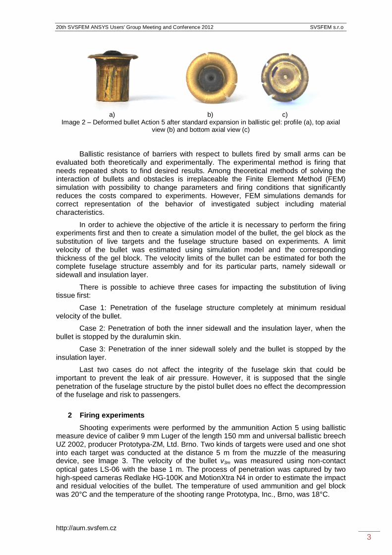
The deformed bullet is shown in Image 2. A significant increase of the front area increases the level of energy transmitted into the target and thus increases the wound potential of the bullet. On the other hand, the ability of the bullet to penetrate solid obstacles decreases. Wound potential and piercing potential of the bullet are intertwined.
1.3 Article objectives and methods
One aim of the article is setting the limit velocities of undeformed and deformed bullets with respect to the interest targets that are the gel block as the primary target and the fuselage structure as the secondary target. Knowing those limits is important for understanding the mechanism of interaction between the bullet and the obstacle and also in order to assess the extent of damage of the outer aircraft surface by penetrating bullet.
20th SVSFEM ANSYS Users' Group Meeting and Conference 2012 SVSFEM s.r.o
http://aum.svsfem.cz 3
a) b) c)
Image 2 – Deformed bullet Action 5 after standard expansion in ballistic gel: profile (a), top axial view (b) and bottom axial view (c)
Ballistic resistance of barriers with respect to bullets fired by small arms can be evaluated both theoretically and experimentally. The experimental method is firing that needs repeated shots to find desired results. Among theoretical methods of solving the interaction of bullets and obstacles is irreplaceable the Finite Element Method (FEM) simulation with possibility to change parameters and firing conditions that significantly reduces the costs compared to experiments. However, FEM simulations demands for correct representation of the behavior of investigated subject including material characteristics.
In order to achieve the objective of the article it is necessary to perform the firing experiments first and then to create a simulation model of the bullet, the gel block as the substitution of live targets and the fuselage structure based on experiments. A limit velocity of the bullet was estimated using simulation model and the corresponding thickness of the gel block. The velocity limits of the bullet can be estimated for both the complete fuselage structure assembly and for its particular parts, namely sidewall or sidewall and insulation layer.
There is possible to achieve three cases for impacting the substitution of living tissue first:
Case 1: Penetration of the fuselage structure completely at minimum residual velocity of the bullet.
Case 2: Penetration of both the inner sidewall and the insulation layer, when the bullet is stopped by the duralumin skin.
Case 3: Penetration of the inner sidewall solely and the bullet is stopped by the insulation layer.
Last two cases do not affect the integrity of the fuselage skin that could be important to prevent the leak of air pressure. However, it is supposed that the single penetration of the fuselage structure by the pistol bullet does no effect the decompression of the fuselage and risk to passengers.
2 Firing experiments
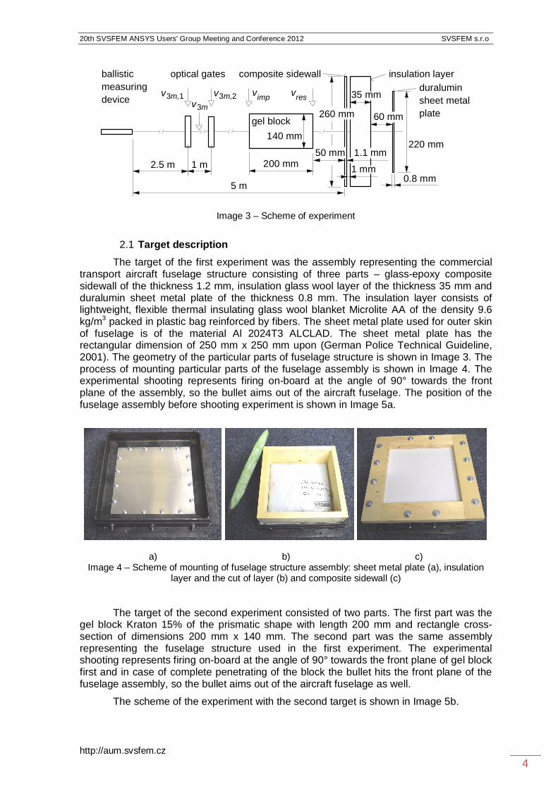
Shooting experiments were performed by the ammunition Action 5 using ballistic measure device of caliber 9 mm Luger of the length 150 mm and universal ballistic breech UZ 2002, producer Prototypa-ZM, Ltd. Brno. Two kinds of targets were used and one shot into each target was conducted at the distance 5 m from the muzzle of the measuring device, see Image 3. The velocity of the bullet v3m was measured using non-contact optical gates LS-06 with the base 1 m. The process of penetration was captured by two high-speed cameras Redlake HG-100K and MotionXtra N4 in order to estimate the impact and residual velocities of the bullet. The temperature of used ammunition and gel block was 20°C and the temperature of the shooting range Prototypa, Inc., Brno, was 18°C.
20th SVSFEM ANSYS Users' Group Meeting and Conference 2012 SVSFEM s.r.o
http://aum.svsfem.cz 4
Image 3 – Scheme of experiment
2.1 Target description
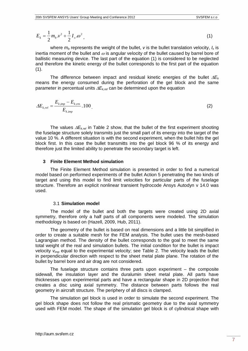
The target of the first experiment was the assembly representing the commercial transport aircraft fuselage structure consisting of three parts – glass-epoxy composite sidewall of the thickness 1.2 mm, insulation glass wool layer of the thickness 35 mm and duralumin sheet metal plate of the thickness 0.8 mm. The insulation layer consists of lightweight, flexible thermal insulating glass wool blanket Microlite AA of the density 9.6 kg/m3 packed in plastic bag reinforced by fibers. The sheet metal plate used for outer skin of fuselage is of the material Al 2024T3 ALCLAD. The sheet metal plate has the rectangular dimension of 250 mm x 250 mm upon (German Police Technical Guideline, 2001). The geometry of the particular parts of fuselage structure is shown in Image 3. The process of mounting particular parts of the fuselage assembly is shown in Image 4. The experimental shooting represents firing on-board at the angle of 90° towards the front plane of the assembly, so the bullet aims out of the aircraft fuselage. The position of the fuselage assembly before shooting experiment is shown in Image 5a.
a) b) c)
Image 4 – Scheme of mounting of fuselage structure assembly: sheet metal plate (a), insulation layer and the cut of layer (b) and composite sidewall (c)
The target of the second experiment consisted of two parts. The first part was the gel block Kraton 15% of the prismatic shape with length 200 mm and rectangle cross-section of dimensions 200 mm x 140 mm. The second part was the same assembly representing the fuselage structure used in the first experiment. The experimental shooting represents firing on-board at the angle of 90° towards the front plane of gel block first and in case of complete penetrating of the block the bullet hits the front plane of the fuselage assembly, so the bullet aims out of the aircraft fuselage as well.
The scheme of the experiment with the second target is shown in Image 5b.
2.5 m 1 m
ballisticmeasuringdevice
optical gates
v3m,1
gel block
vresvimp
200 mm
140 mm
v3m,2v3m
220 mm
duraluminsheet metalplate
composite sidewall insulation layer
60 mm
35 mm
1 mm0.8 mm
1.1 mm
260 mm
50 mm
5 m

20th SVSFEM ANSYS Users' Group Meeting and Conference 2012 SVSFEM s.r.o
http://aum.svsfem.cz 5
a) b) Image 5 – Scheme of firing experiment: fuselage structure assembly (a) and fuselage structure
assembly with forward gel block representing the live target hit first (b)
2.2 Experimental results
The experimental results of bullet velocities and energies of the bullet are shown in Table 2.
Table 2 Results of experimental shooting
No. of shot
v3m,1 v3m,,2 v3m vimp vres Ek,imp Ek,res Ek Ek,rel
m/s m/s m/s m/s m/s J J J % 1 442.7 442.8 442.75 436 414 580 523 57 10 2 457.8 457.9 457.85 451 92 620 26 595 96
In the first experiment the bullet penetrated the fuselage assembly as the secondary target with surplus of energy of the value Ek,res = 523 J. The character of the hollows is shown in Image 6. The penetration of the composite sidewall shown in Image 6a and 6d caused cylindrical hollow of the diameter 6.2 mm with torn fibers. It is visible at the back side of the composite sidewall a delamination process of the size approx. 35 mm x 35 mm, see Image 6d. The penetration of the insulation layer shown in Image 6b and 6e caused irregular hollow of the diameter approx. 6.9 mm with torn plastic bag and fibers and the dimension and shape of both hollows is very similar. The penetration of the duralumin sheet metal plate shown in Image 6c and 6f created a regular cylindrical hollow of the diameter 8.6 mm with relatively small plastic deformation around the hollow with teared rim. The character of hollow proves that the bullet lacks the expansion; i. e. the deformed front part of the bullet did not exceed the caliber of the bullet.
The deformed bullet was not found after the shooting, so the exact character of the bullet expansion is not known. It is supposed, that the bullet is slightly deformed on its front part and shorten in length without the expansion as it is documented on similar experiment presented in (Hub, 2011).
In the second experiment the bullet penetrated the gel block as the primary target causing the temporary cavity in it and having reduced residual kinetic energy of the value Ek,res = 26 J. Such energy was not sufficient to penetrate even the first part of the secondary target and the bullet was bounced off the composite layer leaving behind small damage on the surface, see Image 7a. On the back side of the composite sidewall it is slightly visible delamination area of the dimension approx. 25 mm x 25 mm, see Image 7b. The shape of deformed bullet is shown in Image 7c. The bullet is expanded after

20th SVSFEM ANSYS Users' Group Meeting and Conference 2012 SVSFEM s.r.o
http://aum.svsfem.cz 6
penetration of the gel block, therefore the front area of the bullet is increased, see Table 1, and the bullet needs more energy to penetrate the following obstacle.
a) b) c)
d) e) f) Image 6 – Results of the 1st experiment - hollows in parts of the secondary target: front side of the composite sidewall (a), front side of the insulation layer (b), front side of duralumin skin (c), back
side of the composite sidewall (d), back side of the insulation layer (e), back side of the duralumin skin (f)
a) b) c) Image 7 – Results of the 2nd experiment – damaged surface of the front part of the composite
sidewall (a), the back side of the composite sidewall (b) and deformed bullet (c)
The amount of energy given to the target is described through kinetic energy of the bullet. The kinetic energy of the bullet is generally described as the sum of translation and rotation energies upon equation
10 mm10 mm10 mm
10 mm10 mm10 mm
10 mm
10 mm
20th SVSFEM ANSYS Users' Group Meeting and Conference 2012 SVSFEM s.r.o
http://aum.svsfem.cz 7
22
21
21 .Iv.mE xbk , (1)
where mb represents the weight of the bullet, v is the bullet translation velocity, Ix is inertia moment of the bullet and is angular velocity of the bullet caused by barrel bore of ballistic measuring device. The last part of the equation (1) is considered to be neglected and therefore the kinetic energy of the bullet corresponds to the first part of the equation (1).
The difference between impact and residual kinetic energies of the bullet Ek means the energy consumed during the perforation of the gel block and the same parameter in percentual units Ek,rel can be determined upon the equation
100.E
EEE
imp,k
res,kimp,krel,k
. (2)
The values Ek,rel in Table 2 show, that the bullet of the first experiment shooting the fuselage structure solely transmits just the small part of its energy into the target of the value 10 %. A different situation is with the second experiment, when the bullet hits the gel block first. In this case the bullet transmitts into the gel block 96 % of its energy and therefore just the limited ability to penetrate the secondary target is left.
3 Finite Element Method simulation
The Finite Element Method simulation is presented in order to find a numerical model based on performed experiments of the bullet Action 5 penetrating the two kinds of target and using this model to find limit velocities for particular parts of the fuselage structure. Therefore an explicit nonlinear transient hydrocode Ansys Autodyn v 14.0 was used.
3.1 Simulation model
The model of the bullet and both the targets were created using 2D axial symmetry, therefore only a half parts of all components were modeled. The simulation methodology is based on (Hazell, 2009, Hub, 2011).
The geometry of the bullet is based on real dimensions and a little bit simplified in order to create a suitable mesh for the FEM analysis. The bullet uses the mesh-based Lagrangian method. The density of the bullet corresponds to the goal to meet the same total weight of the real and simulation bullets. The initial condition for the bullet is impact velocity vimp equal to the experimental velocity; see Table 2. The velocity leads the bullet in perpendicular direction with respect to the sheet metal plate plane. The rotation of the bullet by barrel bore and air drag are not considered.
The fuselage structure contains three parts upon experiment – the composite sidewall, the insulation layer and the duralumin sheet metal plate. All parts have thicknesses upon experimental parts and have a rectangular shape in 2D projection that creates a disc using axial symmetry. The distance between parts follows the real geometry in aircraft structure. The periphery of all discs is clamped.
The simulation gel block is used in order to simulate the second experiment. The gel block shape does not follow the real prismatic geometry due to the axial symmetry used with FEM model. The shape of the simulation gel block is of cylindrical shape with

20th SVSFEM ANSYS Users' Group Meeting and Conference 2012 SVSFEM s.r.o
http://aum.svsfem.cz 8
diameter of 140 mm and length of 200 mm. The gel block uses the mesh-free particle based Smooth Particle Hydrodynamics (SPH) method and the size of particles is 1 mm.
The character and discretization of the simulation model of the bullet Action 5 and both the targets is shown in Image 8.
Image 8 – Character and discretization of 2D simulation model
The main parameter for validating the simulation model is residual velocity of the bullet when penetrating particular parts of target. In the case of the second experiment the next parameter is represented by the geometry of deformed bullet as well.
3.2 Material characteristics
The gel block as the primary target is represented by retrieved and modified model WATER taken from Autodyn library due to the limited published data available on the dynamic material properties of used materials. This model uses shock equation of state relating hydrodynamic pressure with parameters = 760 kg/m3, C0 = 1647 m s-1 and S1 = 1.921.
The fuselage structure as the secondary target consists of three parts.
The composite sidewall uses also retrieved model taken from Autodyn library GLASS-EPXY with density = 1840 kg/m3. This model uses Puff equation of state covering the behavior of material from cold shocked regions to hot, highly expanded regions, with following parameters: A1 = 12130 MPa, A2 = 17980 MPa, Gruneisen coefficient 0.15, expansion coefficient 0.25 and sublimation energy 2 MJ/kg. Next the composite sidewall uses von Mises strength constitutive model premising that the yield stress has a constant value with shear modulus 4000 MPa and yield stress 143.1 MPa. The tensile pressure failure model of composite sidewall allows a maximum hydrodynamic tensile limit to be specified and has the value of -159 MPa. Also erosion is introduced in form of instantaneous geometric strain of the value 2.
The insulation layer is simplified and it is considered to be of one homogenous material without dividing between the glass wool blanket and reinforced plastic bag. Dynamic behavior of the insulation layer is described using easy linear equation of state and erosion failure model in form of instantaneous geometric strain of the value 2. Bulk modulus is considered of the value 1 kPa
gel block composite sidewall
isolation layer
duraluminsheet metalplate
bullet Action 5

20th SVSFEM ANSYS Users' Group Meeting and Conference 2012 SVSFEM s.r.o
http://aum.svsfem.cz 9
A sheet metal plate made of aluminum alloy ASTM 2024-T3 is to some extend available in the Autodyn library. The equivalent designation of used material is upon ISO AlCu4Mg1, DIN AlCuMg2 and ASME SB211. The hydrodynamic shock equation of state of the alloy 2024-T3 relating hydrodynamic pressure, the local density and local specific energy is in Gruneisen form (Steinberg, 1996):
HH ee.pp , (3)
where p is hydrostatic pressure, pH is Hugoniot pressure, = 2.0 is Gruneisen Gamma, = 2780 kg/m3 is density of the alloy, e is internal energy, eH is Hugoniot energy. The pressure is based on a linear Hugoniot relation between shock velocity us and particle velocity up
ps u.SCu 10 , (4)
where C0 = 5328 m/s is initial sound speed and S1 = 1.338 is Hugoniot slope coefficient.
The constitutive model expressing the relation between the shear stress and strain uses for the alloy 2024-T3 a Johnson-Cook model representing the strength behavior of materials subjected to large strains, high strain rates and high temperatures as it is the solving high-speed impact. The empirical Johnson-Cook model (Johnson, 1983) decouples the effect of strain, strain rate and temperature for the von Mises flow stress
m**n Tln.C.BA 11 , (5)
where is the equivalent plastic strain, 0 /* is the dimensionless plastic
strain rate for 0 = 1.0 s-1 and *T is the homologous temperature. The five material constants are as follows: A = 368.5 MPa is the yield uniaxial stress, B = 683.9 MPa is the strain hardening coefficient, n = 0.73 is the strain hardening exponent, C = 0.0083 is the strain hardening coefficient and m = 1.7 is the thermal softening exponent. The actual values of the constitutive constant used for the material 2024-T3 are set according to (DOT, 2003, Doubrava, 2009).
The failure criterion describes the damage behavior and for the alloy 2024-T3 it is used a convenient model proposed by Johnson-Cook (Johnson, 1985). This model assumes that damage accumulates in the material element during plastic straining and that the material breaks when the damage reaches a critical value. This model is constructed in a very similar way to the Johnson-Cook strength model in that it consists of three independent terms that define the dynamic fracture strain as a function of pressure, strain rate and temperature
**.Df TDlnDe.DD
*
5421 113 . (6)
The damage variable D takes values between 0 and 1. D = 0 corresponds to the undamaged material and D = 1 corresponds to the fully broken material. The evolution of
20th SVSFEM ANSYS Users' Group Meeting and Conference 2012 SVSFEM s.r.o
http://aum.svsfem.cz 10
D is given by the accumulated incremental effective plastic strain divided by the current strain at fracture
fD
. (7)
The actual values for the fracture Johnson-Cook material model of 2024-T3 alloy according (DOT, 2003, Doubrava, 2009) are following: D1 = 0.112, D2 = 0,123, D3 = 1.5, D4 = 0.007, D5 = 0.
The bullet Action 5 used in simulation is described through various models.
The gilding metal jacket uses a shock equation of state with values: = 7985 kg/m3, = 2.0, C0 = 3958 m/s and S1 = 1.497. The constitutive model of modified COPPER model retrieved from Autodyn library uses the Piecewise Johnson-Cook model. This model is a modification of the Johnson-Cook model, where the dependence on effective plastic strain represented by the term (A + B.n) in equation 5 is replaced by a piecewise linear function of yield stress Y versus effective plastic strain P. The strain rate dependence and thermal softening term remain the same as in the Johnson-Cook model. The parameters used in gilding metal jacket simulation: G = 68800 MPa, Y0 = 120 MPa, P1 = 0.3, Y1 = 450 MPa, Y2 = 450 MPa, m = 1.
The plastic cap of the bullet considers the polyurethane material POLYURETH retrieved from Autodyn library as well. This model uses the simplest shock equation of state that can be determined by assuming that the pressure is independent of the internal energy and that changes in the material density are small and reversible. Expressing the pressure as a Taylor series in the density and retaining only the linear terms leads to the linear equation of state
.Kp , (8)
where K = 2000 MPa is the bulk modulus and = 0 – 1 is the compression (Autodyn, 2006), where 0 = 1265 kg/m3.
Strength model of the plastic cap as expressing the resistance of given material to shearing forces uses simple elastic form and failure model uses the maximum value of principal stress. The shear modulus has the value of 5 MPa.
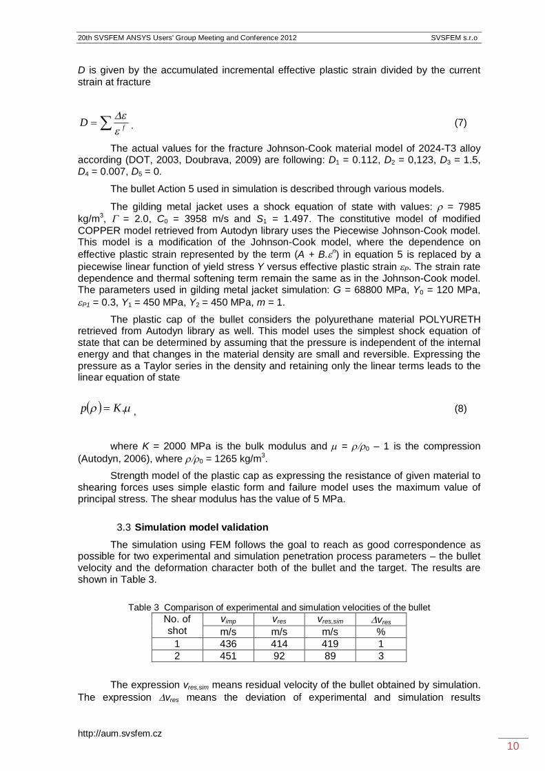
3.3 Simulation model validation
The simulation using FEM follows the goal to reach as good correspondence as possible for two experimental and simulation penetration process parameters – the bullet velocity and the deformation character both of the bullet and the target. The results are shown in Table 3.
Table 3 Comparison of experimental and simulation velocities of the bullet
No. of shot
vimp vres vres,sim vres
m/s m/s m/s % 1 436 414 419 1 2 451 92 89 3
The expression vres,sim means residual velocity of the bullet obtained by simulation.
The expression vres means the deviation of experimental and simulation results
20th SVSFEM ANSYS Users' Group Meeting and Conference 2012 SVSFEM s.r.o
http://aum.svsfem.cz 11
estimated as the relation between the difference of both experimental and simulation residual velocities with respect to the lower value of both residual velocities.
When comparing the experimental and simulation results, the correspondence between both velocities is very good.
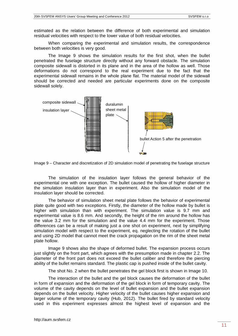
The Image 9 shows the simulation results for the first shot, when the bullet penetrated the fuselage structure directly without any forward obstacle. The simulation composite sidewall is distorted in its plane and in the area of the hollow as well. Those deformations do not correspond to the real experiment due to the fact that the experimental sidewall remains in the whole plane flat. The material model of the sidewall should be corrected and needed are particular experiments done on the composite sidewall solely.
Image 9 – Character and discretization of 2D simulation model of penetrating the fuselage structure
The simulation of the insulation layer follows the general behavior of the experimental one with one exception. The bullet caused the hollow of higher diameter in the simulation insulation layer than in experiment. Also the simulation model of the insulation layer should be corrected.
The behavior of simulation sheet metal plate follows the behavior of experimental plate quite good with two exceptions. Firstly, the diameter of the hollow made by bullet is higher with simulation than with experiment. The simulation value is 9.7 mm and experimental value is 8.6 mm. And secondly, the height of the rim around the hollow has the value 3.2 mm for the simulation and the value 4.4 mm for the experiment. Those differences can be a result of making just a one shot on experiment, next by simplifying simulation model with respect to the experiment, eq. neglecting the rotation of the bullet and using 2D model that cannot meet the crack propagation on the rim of the sheet metal plate hollow.
Image 9 shows also the shape of deformed bullet. The expansion process occurs just slightly on the front part, which agrees with the presumption made in chapter 2.2. The diameter of the front part does not exceed the bullet caliber and therefore the piercing ability of the bullet remains standard. The plastic cap is pushed inside of the bullet cavity.
The shot No. 2 when the bullet penetrates the gel block first is shown in Image 10.
The interaction of the bullet and the gel block causes the deformation of the bullet in form of expansion and the deformation of the gel block in form of temporary cavity. The volume of the cavity depends on the level of bullet expansion and the bullet expansion depends on the bullet velocity. Higher velocity of the bullet causes higher expansion and larger volume of the temporary cavity (Hub, 2012). The bullet fired by standard velocity used in this experiment expresses almost the highest level of expansion and the
bullet Action 5 after the penetration
composite sidewall
insulation layerduraluminsheet metalplate
20th SVSFEM ANSYS Users' Group Meeting and Conference 2012 SVSFEM s.r.o
http://aum.svsfem.cz 12
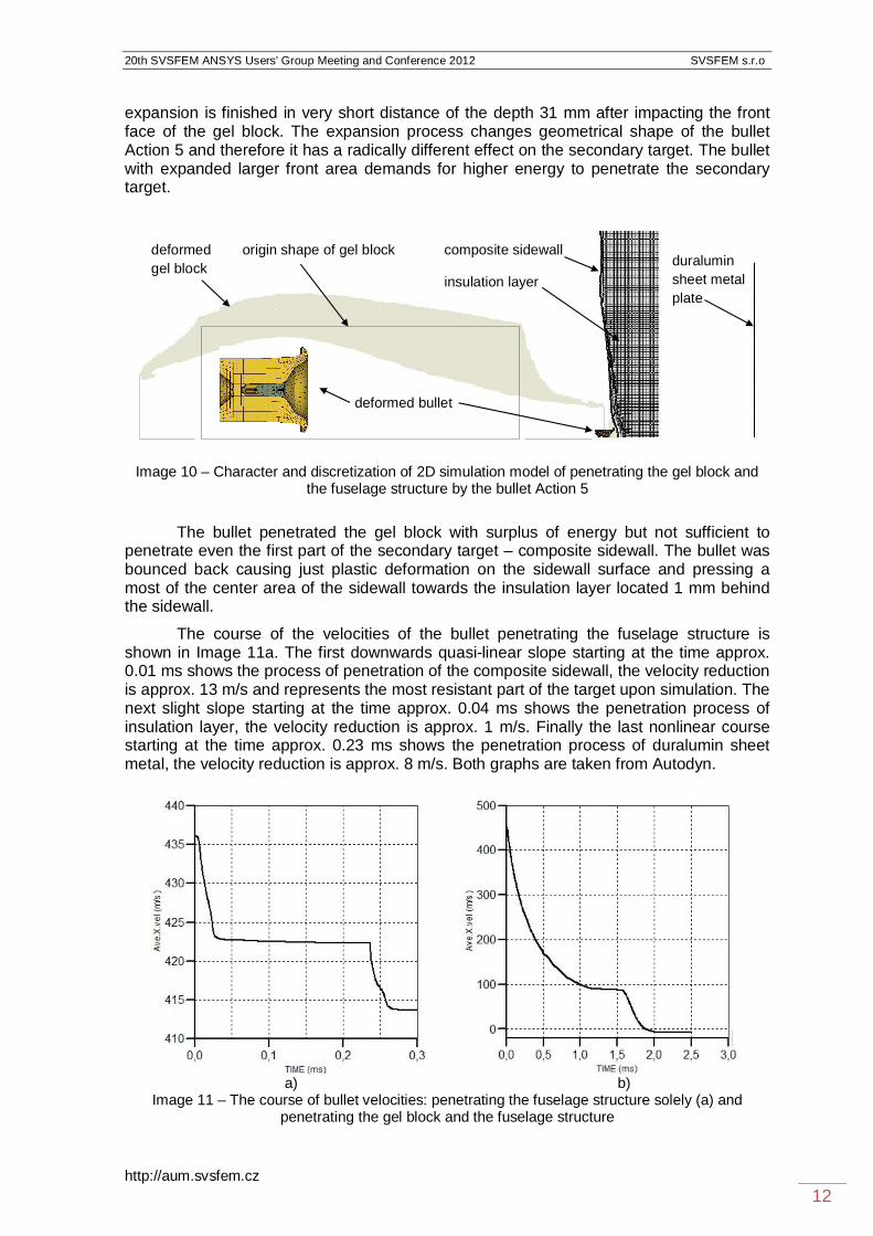
expansion is finished in very short distance of the depth 31 mm after impacting the front face of the gel block. The expansion process changes geometrical shape of the bullet Action 5 and therefore it has a radically different effect on the secondary target. The bullet with expanded larger front area demands for higher energy to penetrate the secondary target.
Image 10 – Character and discretization of 2D simulation model of penetrating the gel block and the fuselage structure by the bullet Action 5
The bullet penetrated the gel block with surplus of energy but not sufficient to penetrate even the first part of the secondary target – composite sidewall. The bullet was bounced back causing just plastic deformation on the sidewall surface and pressing a most of the center area of the sidewall towards the insulation layer located 1 mm behind the sidewall.
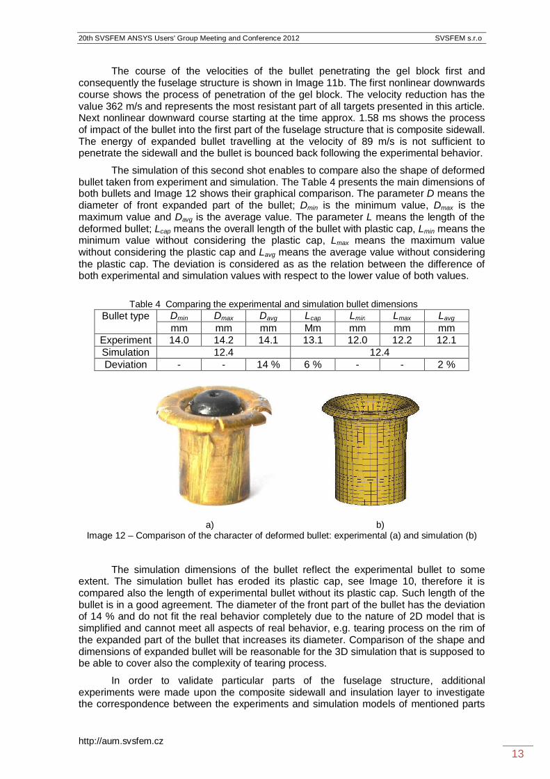
The course of the velocities of the bullet penetrating the fuselage structure is shown in Image 11a. The first downwards quasi-linear slope starting at the time approx. 0.01 ms shows the process of penetration of the composite sidewall, the velocity reduction is approx. 13 m/s and represents the most resistant part of the target upon simulation. The next slight slope starting at the time approx. 0.04 ms shows the penetration process of insulation layer, the velocity reduction is approx. 1 m/s. Finally the last nonlinear course starting at the time approx. 0.23 ms shows the penetration process of duralumin sheet metal, the velocity reduction is approx. 8 m/s. Both graphs are taken from Autodyn.
a) b)
Image 11 – The course of bullet velocities: penetrating the fuselage structure solely (a) and penetrating the gel block and the fuselage structure
composite sidewall
insulation layerduraluminsheet metalplate
deformedgel block
origin shape of gel block
deformed bullet
20th SVSFEM ANSYS Users' Group Meeting and Conference 2012 SVSFEM s.r.o
http://aum.svsfem.cz 13
The course of the velocities of the bullet penetrating the gel block first and consequently the fuselage structure is shown in Image 11b. The first nonlinear downwards course shows the process of penetration of the gel block. The velocity reduction has the value 362 m/s and represents the most resistant part of all targets presented in this article. Next nonlinear downward course starting at the time approx. 1.58 ms shows the process of impact of the bullet into the first part of the fuselage structure that is composite sidewall. The energy of expanded bullet travelling at the velocity of 89 m/s is not sufficient to penetrate the sidewall and the bullet is bounced back following the experimental behavior.
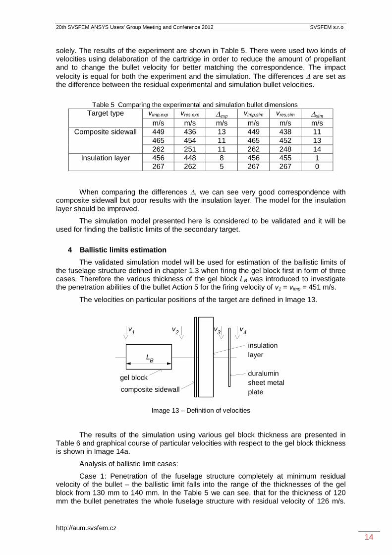
The simulation of this second shot enables to compare also the shape of deformed bullet taken from experiment and simulation. The Table 4 presents the main dimensions of both bullets and Image 12 shows their graphical comparison. The parameter D means the diameter of front expanded part of the bullet; Dmin is the minimum value, Dmax is the maximum value and Davg is the average value. The parameter L means the length of the deformed bullet; Lcap means the overall length of the bullet with plastic cap, Lmin means the minimum value without considering the plastic cap, Lmax means the maximum value without considering the plastic cap and Lavg means the average value without considering the plastic cap. The deviation is considered as as the relation between the difference of both experimental and simulation values with respect to the lower value of both values.
Table 4 Comparing the experimental and simulation bullet dimensions
Bullet type Dmin Dmax Davg Lcap Lmin Lmax Lavg mm mm mm Mm mm mm mm
Experiment 14.0 14.2 14.1 13.1 12.0 12.2 12.1 Simulation 12.4 12.4 Deviation - - 14 % 6 % - - 2 %
a) b) Image 12 – Comparison of the character of deformed bullet: experimental (a) and simulation (b)
The simulation dimensions of the bullet reflect the experimental bullet to some extent. The simulation bullet has eroded its plastic cap, see Image 10, therefore it is compared also the length of experimental bullet without its plastic cap. Such length of the bullet is in a good agreement. The diameter of the front part of the bullet has the deviation of 14 % and do not fit the real behavior completely due to the nature of 2D model that is simplified and cannot meet all aspects of real behavior, e.g. tearing process on the rim of the expanded part of the bullet that increases its diameter. Comparison of the shape and dimensions of expanded bullet will be reasonable for the 3D simulation that is supposed to be able to cover also the complexity of tearing process.
In order to validate particular parts of the fuselage structure, additional experiments were made upon the composite sidewall and insulation layer to investigate the correspondence between the experiments and simulation models of mentioned parts
20th SVSFEM ANSYS Users' Group Meeting and Conference 2012 SVSFEM s.r.o
http://aum.svsfem.cz 14
solely. The results of the experiment are shown in Table 5. There were used two kinds of velocities using delaboration of the cartridge in order to reduce the amount of propellant and to change the bullet velocity for better matching the correspondence. The impact velocity is equal for both the experiment and the simulation. The differences are set as the difference between the residual experimental and simulation bullet velocities.
Table 5 Comparing the experimental and simulation bullet dimensions
Target type vimp,exp vres,exp exp vimp,sim vres,sim sim
m/s m/s m/s m/s m/s m/s Composite sidewall 449 436 13 449 438 11
465 454 11 465 452 13 262 251 11 262 248 14
Insulation layer 456 448 8 456 455 1 267 262 5 267 267 0
When comparing the differences , we can see very good correspondence with composite sidewall but poor results with the insulation layer. The model for the insulation layer should be improved.
The simulation model presented here is considered to be validated and it will be used for finding the ballistic limits of the secondary target.
4 Ballistic limits estimation
The validated simulation model will be used for estimation of the ballistic limits of the fuselage structure defined in chapter 1.3 when firing the gel block first in form of three cases. Therefore the various thickness of the gel block LB was introduced to investigate the penetration abilities of the bullet Action 5 for the firing velocity of v1 = vimp = 451 m/s.
The velocities on particular positions of the target are defined in Image 13.
Image 13 – Definition of velocities
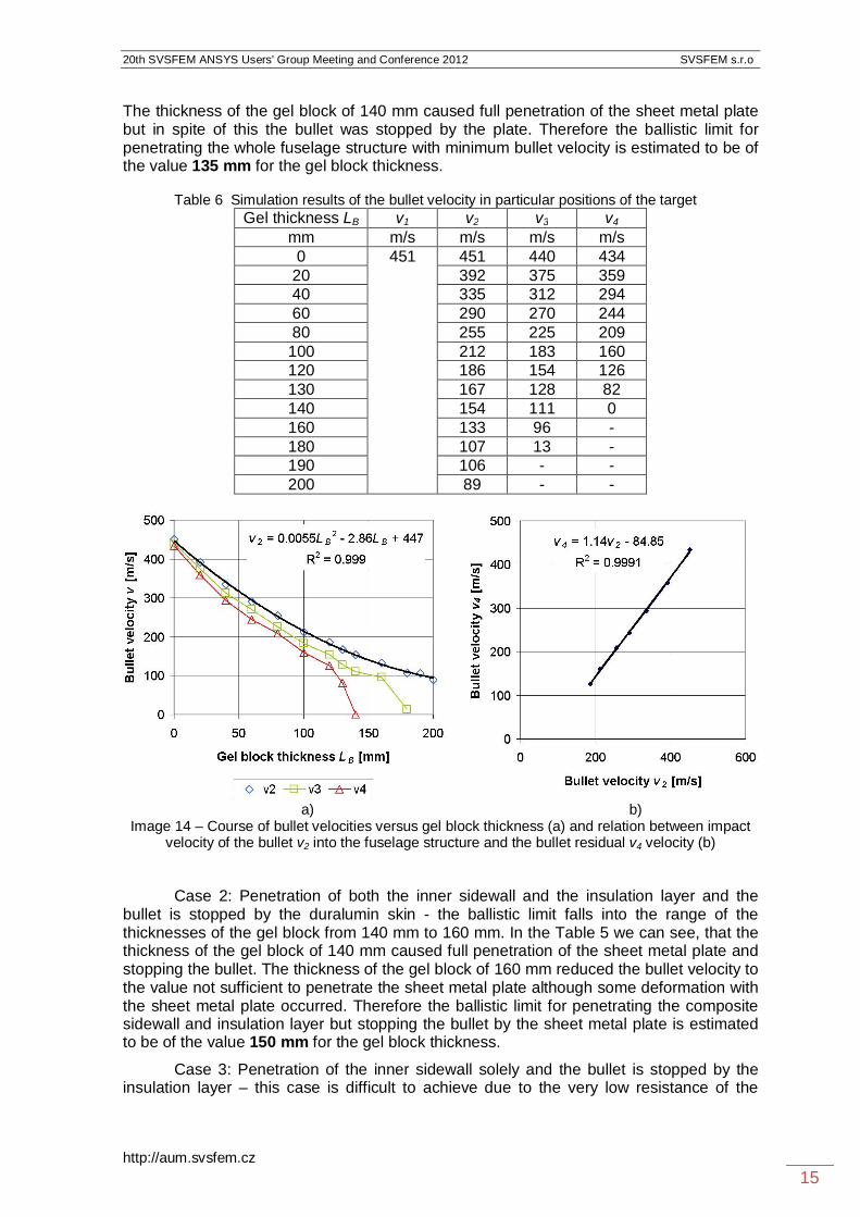
The results of the simulation using various gel block thickness are presented in Table 6 and graphical course of particular velocities with respect to the gel block thickness is shown in Image 14a.
Analysis of ballistic limit cases:
Case 1: Penetration of the fuselage structure completely at minimum residual velocity of the bullet – the ballistic limit falls into the range of the thicknesses of the gel block from 130 mm to 140 mm. In the Table 5 we can see, that for the thickness of 120 mm the bullet penetrates the whole fuselage structure with residual velocity of 126 m/s.
gel block
v2v1
duraluminsheet metalplatecomposite sidewall
insulationlayer
v3 v4
LB
20th SVSFEM ANSYS Users' Group Meeting and Conference 2012 SVSFEM s.r.o
http://aum.svsfem.cz 15
The thickness of the gel block of 140 mm caused full penetration of the sheet metal plate but in spite of this the bullet was stopped by the plate. Therefore the ballistic limit for penetrating the whole fuselage structure with minimum bullet velocity is estimated to be of the value 135 mm for the gel block thickness.
Table 6 Simulation results of the bullet velocity in particular positions of the target
Gel thickness LB v1 v2 v3 v4 mm m/s m/s m/s m/s 0 451 451 440 434
20 392 375 359 40 335 312 294 60 290 270 244 80 255 225 209 100 212 183 160 120 186 154 126 130 167 128 82 140 154 111 0 160 133 96 - 180 107 13 - 190 106 - - 200 89 - -
a) b) Image 14 – Course of bullet velocities versus gel block thickness (a) and relation between impact
velocity of the bullet v2 into the fuselage structure and the bullet residual v4 velocity (b)
Case 2: Penetration of both the inner sidewall and the insulation layer and the bullet is stopped by the duralumin skin - the ballistic limit falls into the range of the thicknesses of the gel block from 140 mm to 160 mm. In the Table 5 we can see, that the thickness of the gel block of 140 mm caused full penetration of the sheet metal plate and stopping the bullet. The thickness of the gel block of 160 mm reduced the bullet velocity to the value not sufficient to penetrate the sheet metal plate although some deformation with the sheet metal plate occurred. Therefore the ballistic limit for penetrating the composite sidewall and insulation layer but stopping the bullet by the sheet metal plate is estimated to be of the value 150 mm for the gel block thickness.
Case 3: Penetration of the inner sidewall solely and the bullet is stopped by the insulation layer – this case is difficult to achieve due to the very low resistance of the

20th SVSFEM ANSYS Users' Group Meeting and Conference 2012 SVSFEM s.r.o
http://aum.svsfem.cz 16
insulation layer against penetration by the bullet Action 5. Anyway, the ballistic limit falls into the range of the thicknesses of the gel block from 180 mm to 190 mm. The Table 5 shows that the thickness of the gel block of 180 mm enables for the bullet to penetrate the insulation layer with residual velocity of 13 m/s. The thickness of the gel block of 200 mm reduces the bullet velocity to the value not sufficient to penetrate the first part of the fuselage structure – composite sidewall. Therefore the ballistic limit for penetrating the composite sidewall but stopping the bullet by the insulation layer is estimated to be of the value 185 mm for the gel block thickness.
The course of velocity v2 impacting the fuselage structure after penetrating the gel block is fitted with polynomial approximation of the second order, see graph in Image 14a. This approximation enables to estimate the residual velocity of the bullet with respect to the gel block thickness LB; the thickness LB is set in [mm], the velocities in [m/s]:
447.86.2.0055.0 2
2 BB LLv . (9)
The graph in Image 14b shows the relation between the residual velocity leaving the fuselage structure v4 with respect to the velocity v2 impacting the fuselage structure for the region of gel block thickness of 0 mm to 120 mm only. In this region the bullet penetrates the both the gel block and the fuselage structure completely with surplus of energy. The value 130 mm cannot be taken into account even having the complete penetration of the bullet due to the nonlinear character of dependence of the velocity v4 with respect to the velocity v2. A proposed linear approximation enables to estimate the residual velocity v4 depending on the impact velocity v2 in form:
85.84.14.1 24 vv . (10)
Using both equations 9 and 10 is possible to estimate the residual velocity of the bullet penetrating both the gel block and fuselage structure v4 with respect to the gel block thickness LB. Proposed procedure is valid only for the region of gel block thickness from the value 0 mm to 120 mm.
5 Discussion
The investigated fuselage structure expresses just a little ballistic resistance upon performed FEM simulation when facing the impact of Action 5 projectile. One of the most probably impacted airplane structures is in case of firing on-board the fuselage structure as the largest are of the airplane with very poor ballistic resistance. The bullet Action 5 is able to penetrate the fuselage structure when impacting the structure directly with surplus of energy.
In case of impacting the substitute material first, the geometry of the bullet changes due to the expansion and piercing ability decreases. In spite of this, the bullet is able to penetrate the fuselage structure to large extend of the gel block thickness up to the value approx. 130 mm. Exceeding this value the bullet damages the sheet metal skin in form of incomplete penetration up to the value of 150 mm. The damage of the outer sheet metal plate should not occur exceeding the gel block thickness of 190 mm.
The bullet Action 5 proved also its expansion ability during penetration the soft target. The expansion does not progress in case of penetrating the hard target representing by the fuselage structure when firing directly.

20th SVSFEM ANSYS Users' Group Meeting and Conference 2012 SVSFEM s.r.o
http://aum.svsfem.cz 17
From the point of view of damage of the outer skin of the airplane is the penetration of the expanded bullet travelling at low velocity much more dangerous than penetration by the same bullet but travelling at high velocity without expansion.
However, the most common transport airplane structure is of semimonocoque type and such structure is able to distribute the load easily to adjacent parts in case of damage. Therefore the effect of skin damage due to isolated or even the multiple complete penetration of the Action 5 bullet on airframe strength and stiffness is supposed to be negligible (Hub, 2009). The danger of damaging the inner systems by the bullet with more serious consequences remains to be occurred.
6 Conclusion
Experiments and simulations done upon the gel block and the fuselage structure targets have shown a significant difference in piercing ability of the bullet Action 5 under various target conditions. In case of firing directly to the secondary target that is fuselage structure, the bullet penetrates all parts of the fuselage structure easily with high surplus of energy. After the simulated penetration of thin and thick parts of the human body that can be represented by the arm above the elbow and thighs of the leg, penetration ability of the bullet decreases significantly partly due to the expansion of the bullet and increasing the cross section of the bullet and partly due to lower velocity of the bullet impact as a result of deceleration in the test gel block. When considering a possible damage of the fuselage skin, the least favourable situation corresponds to the firing through gel block of the thickness less than 150 mm. In this case a large damage could occurr due to tear of the skin caused by low impact energy and expanded bullet, which could have negative consequences in real flight.
A numerical model has been developed upon firing experiments that simulates the penetration of the substitute material and subsequent perforation of fuselage structure used in airplane structures by bullet of mentioned projectile.
The FEM simulation results have shown:
a good possibility to use the software Ansys Autodyn for modelling the penetration process, to consider the boundary conditions and to take an advantage of implemented material models with the possibility of modification to meet the real behaviour of the simulated objects,
a good correlation between the experimental and simulation results in terms of comparison the residual velocities after penetration of the bullet through the both targets,
a crucial influence of material characteristics for simulation the experimental shooting,
a methodology for evaluating the residual velocity of the bullet penetrating both targets with respect to the gel block thickness,
a limited ballistic resistance of investigated fuselage structure facing the impact of the projectile Action-5,
higher relevance of the results demands for wider extent of experimental shooting especially for particular parts of the taregt and performing the 3D FEM simulation.
References AUTODYN, 2006. Autodyn Training Course. Autodyn Workbench release 11.0

20th SVSFEM ANSYS Users' Group Meeting and Conference 2012 SVSFEM s.r.o
http://aum.svsfem.cz 18
DOT/FEE/AR-03/57, 2009. Failure modelling of titanium 6Al-4V and alumunium 2024-T3 with the Johnson-Cook material model. Federal Aviation Administration. 24 p. DOUBRAVA R., 2009. Simulation of rigid projectile impact on the real aircraft structure. Czech Aerospace Proceedings, 2009, No.2, p. 18 – 20. ISSN 1211-877X GERMAN POLICE TECHNICAL GUIDELINE (Technische Richtline Patrone 9 mm x 19, Schadstoffreduziert des Unterausschusses Fuhrungs- und Einsatzmittel), 2011. Munster: Polizeitechnisches Institut der Polizei-Fuhrungsakademie, 63 p. HAZELL P., 2009. Numerical simulations and experimental observations of the 5.65-mm L2A2 bullet perforating steel targets of two hardness values. Journal of Battlefield Technology, March 2009, Vol. 6, No. 1, p. 1 – 4. ISSN 14405113. HUB J., KOMENDA J., RACEK F., 2011. Ballistic resistance of duralumin sheet metal plate using forward obstacle. In.: International Conference in Military Technology Proceedings ICMT’11, Brno, 10 – 13 May 2011. Brno : JALOVECKY R. and STEFFEK A. (ed.), p. 1683 1692. ISBN 978-80-7231-787-5. HUB J., KOMENDA J., 2012. Analysis of Terminal-Ballistic Behaviour of Pistol Bullet Penetrating the Block of Substitute Biological Material. In.: 9th International Armament Conference on Specific aspects of armament & safety technology, Pultusk, 25 - 28 September 2012. Warszawa : CHROMIK R., KIJEWSKI J., LECIEJEWSKI Z. (ed.), p. 344 – 360. JOHNSON G. R., COOK W. H., 1983. A constitutive model and data for metals subjected to large strains, high strain rates and high temperatures. In.: Proceedings 7th International Symposium on Ballistics, The Hague, 1983, p. 541 – 547. JOHNSON G. R., COOK W. H., 1985. Fracture characteristics of three metals subjected to various strains, strain rates, temperatures and pressures. Engineering Fracture Mechanics, 1985, Vol. 21, p. 31 – 48. STEINBERG D. J., 1996. Equation of state and strength properties of selected materials. Lawrence Livermore National Laboratory, 1996, 69 p. Acknowledgement The work presented here in this paper has been supported by the Ministry of Interior of the Czech Republic (security research project VG20112015037).
Contact address: Eng. Juraj Hub, Ph.D.* Department of Aircraft and Rocket Technologies, University of Defence, Kounicova 65, 662 10 Brno, Czech Republic, email: [email protected], tel.: +420 973 445 189 Accoc. Prof. Eng. Jan Komenda, CSc. Department of Weapons and Ammunition, University of Defence, Kounicova 65, 662 10 Brno, Czech Republic, email: [email protected], tel.: +420 973 445 368