ballistic pressure sensors reference guide
TRANSCRIPT

Ballistic Pressure SensorsReference Guide
Aerospace & Defense Division Toll-Free in USA 866-816-8892 716-684-0001 www.pcb.com
Ballistic Pressure Sensors Reference Guide

2
Ballistic Pressure Sensors Reference Guide
Ballistic Pressure Sensors Reference GuideThis compilation is intended as a reference guide to the characteristics and behavior of firearms and ammunition, andas an introduction to the various types of ballistics measurements that are made.
Dimensions shown on figures are in inches
BALLISTICS TERMINOLOGYANNEALED: Description of metal heated after work hardening to prevent it from being too brittle.
BARREL TIME: Time between the impact of the firing pin on the primer and when the bullet exits the muzzle.
BELT: Area of cartridge case with an increased or reinforced diameter ahead of extractor groove.
BORE: The inside of the barrel of a gun, the inside diameter of the barrel before rifling is cut.
BRASS: Term often applied to empty cartridge cases; an alloy of copper and zinc.
BREECH: The area of a firearm at the rear of the bore that receives the cartridge case.
BULLET: The missile only. Becomes a projectile when in flight.
CALIBER: Approximate bore or groove diameter expressed (in English) in decimals of an inch, otherwise in the metricsystem (millimeters). Example: 38 caliber = 0.38 inches diameter.
CARTRIDGE: A complete, assembled unit of ammunition: Includes case, propellant powder, primer, and bullet.
CASE: The paper, metal or plastic container which holds all the other components of a round of ammunition;sometimes called "hull" or "shell".
CENTER FIRE: Refers to centrally located primer in base of metal cartridges.
CHAMBER: That part of the bore, at the breech, formed to accept and support the cartridge.
FLASH HOLE: The hole leading from the primer pocket into the body of the cartridge case.
GAUGE: Commonly refers to the size of a shot shell (the smaller the number, the larger the shell).
GROOVES: Spiral cuts or impressions in the bore of a gun that causes a bullet to spin as it moves through the barrel.
IGNITION: The setting on fire of the propellant powder charge, by the primer.

3
Ballistic Pressure Sensors Reference Guide
LANDS: The spiral raised portion of a bore remaining after the grooves have been cut or formed.
MAGNUM: A load, or cartridge having greater power. Usually a longer case, or a caliber with exceptionally largerpowder capacity.
MUZZLE: The front end of a barrel; the point at which a projectile leaves the barrel.
NECK: The portion of a cartridge case that grips the bullet.
NECK DOWN: To reduce the diameter of the neck.
POWDER: The propellant materials used in most firearms.
PRESSURE: The pressure exerted by a burning charge of powder in the chamber of a gun.
PRIMER: A small metal cup in a centerfire cartridge containing a detonating mixture, which is used to ignite thepropellant powder. It is seated in the primer pocket.
PRIMER POCKET: The cavity in the base of the cartridge case made to receive and support the primer.
PROOF AMMUNITION: Ammunition made with very accurate controls on the powder quantity and quality fordetermining pressure.
REFERENCE AMMUNITION: Ammunition used to determine a close statistical group of pressure ratings.
RIFLING: Parallel spiral grooves cut into the bore to make the bullet spin and stabilize in flight. Made up of groovesand lands.
RIM: The projecting edge at the base of most cartridge cases upon which the extractor pulls.
RIMFIRE: Refers to a cartridge that features the primer in its rim. Usually found in .22 caliber rounds.
ROUND: A military term meaning one complete cartridge.
SAAMI: Small Arms and Ammunition Manufacturers Institute; the organization that standardizes case and chamberspecifications in the USA.
SHOT: The lead alloy or steel spheres, which are used for the projectiles in smoothbore guns (shotguns).
SHOULDER: The sharply sloping or rounded part of a cartridge case. Joins the neck to the body.
VELOCITY: The speed at which a projectile travels. Measured in feet per second at a given range
4
Ballistic Pressure Sensors Reference Guide
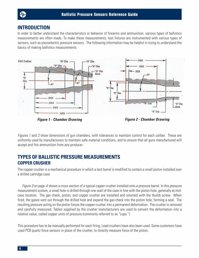
INTRODUCTION In order to better understand the characteristics or behavior of firearms and ammunition, various types of ballisticsmeasurements are often made. To make these measurements, test fixtures are instrumented with various types ofsensors, such as piezoelectric pressure sensors. The following information may be helpful in trying to understand thebasics of making ballistics measurements.
Figures 1 and 2 show dimensions of gun chambers, with tolerances to maintain control for each caliber. These areuniformly used by manufacturers to maintain safe material conditions, and to ensure that all guns manufactured willaccept and fire ammunition from any producer.
TYPES OF BALLISTIC PRESSURE MEASUREMENTS COPPER CRUSHERThe copper crusher is a mechanical procedure in which a test barrel is modified to contain a small piston installed overa drilled cartridge case.
Figure 3 on page 4 shows a cross-section of a typical copper crusher installed onto a pressure barrel. In this pressuremeasurement system, a small hole is drilled through one wall of the case in line with the piston hole, generally at mid-case location. The gas check, piston, and copper crusher are installed and retained with the thumb screw. Whenfired, the gases vent out through the drilled hole and expand the gas check into the piston hole, forming a seal. Theresulting pressure acting on the piston forces the copper crusher into a permanent deformation. The crusher is removedand carefully measured. Tables supplied by the crusher manufacturers are used to convert the deformation into arelative value, called copper units of pressure (commonly referred to as “cups.”)
This procedure has to be manually performed for each firing. Lead crushers have also been used. Some customers haveused PCB quartz force sensors in place of the crusher, to directly measure force of the piston.
Figure 1 - Chamber Drawing Figure 2 - Chamber Drawing

5
Ballistic Pressure Sensors Reference Guide
Figure 3- Copper Crusher
Figure 4 - Universal Receiver Pressure and Velocity Test Barrel

6
Ballistic Pressure Sensors Reference Guide
Figure 4 describes a typical pressure and velocity test barrel made to fit into a universal receiver. The keyway is usedto align the test barrel in the universal receiver, and the extractor slot is used to remove the cartridge case.
The VELOCITY part of the test barrel description deals with external ballistics (outside of the barrel). It is themeasurement of projectile speed and direction beyond the muzzle.
The PRESSURE part of the description deals with interior ballistics (inside of the barrel). Measurements of pressureinside of chamber, cartridge case, and bore can be made by various methods, including copper crusher (older method)or piezoelectric sensor(s).
In addition to these specially made barrels, standard rifle, pistol, and shotgun barrels are also sometimes instrumentedfor pressure measurements.
BALLISTIC SENSOR MEASUREMENT LOCATIONS
Figure 5 shows various locations at which pressure measurements are typically made on small arms ammunition (allsensor locations are dimensioned from the bolt face surface). The following describes these locations, the typicalPCB sensors used for measurements at the locations, and the pressures typically associated with the measurements.
MID-CASE:n Located at approximately mid-point of length of case n PCB Models 109C11, 119B, 119B11n Approximate pressure: rifle 60K psi, pistol or revolver 40K psin For measurements at this location, the copper crusher technique is also used (see Figure 3 )
Figure 5- Pressure Measurement Sensor Locations

7
Ballistic Pressure Sensors Reference Guide
CONFORMAL:n Location - determined by SAAMI- PCB Series 117Bxn Approximate pressure: rifle 60K psi, pistol or revolver 40K psi
CASE MOUTH:n Location at mouth of casen PCB Models 109C11, 119B, 119B11n Approximate pressure: rifle 60K psi, pistol or revolver 40K psi
PORT: n Location at approximately 15 inches from bolt face- for use on semi-automatic or full automatic gunsn PCB Models 109C11, 119B, 119B11n Approximate pressure: rifle 15K psi, pistol 15K psi
CASE TYPES
Case nomenclature for revolver, pistol, rifle, and rimfire in Figures 6 – 9 are almost identical except for externalconfiguration and size, which determines caliber.
Figure 6- Centerfire Pistol Case Figure 7 - Centerfire Revolver Case
Figure 8- Centerfire Rifle Case Figure 9- Rimfire Case
8
Ballistic Pressure Sensors Reference Guide
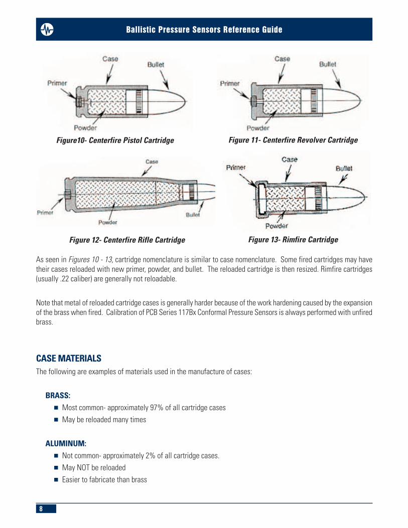
As seen in Figures 10 - 13, cartridge nomenclature is similar to case nomenclature. Some fired cartridges may havetheir cases reloaded with new primer, powder, and bullet. The reloaded cartridge is then resized. Rimfire cartridges(usually .22 caliber) are generally not reloadable.
Note that metal of reloaded cartridge cases is generally harder because of the work hardening caused by the expansionof the brass when fired. Calibration of PCB Series 117Bx Conformal Pressure Sensors is always performed with unfiredbrass.
CASE MATERIALSThe following are examples of materials used in the manufacture of cases:
BRASS:n Most common- approximately 97% of all cartridge casesn May be reloaded many times
ALUMINUM:n Not common- approximately 2% of all cartridge cases. n May NOT be reloadedn Easier to fabricate than brass
Figure10- Centerfire Pistol Cartridge Figure 11- Centerfire Revolver Cartridge
Figure 12- Centerfire Rifle Cartridge Figure 13- Rimfire Cartridge
9
Ballistic Pressure Sensors Reference Guide
STEEL:n Not common- approximately 1% of all cartridge cases n May not be reloadedn Mainly for military usen Extended shelf life; sealed primers.
SHOT SHELL CARTRIDGES
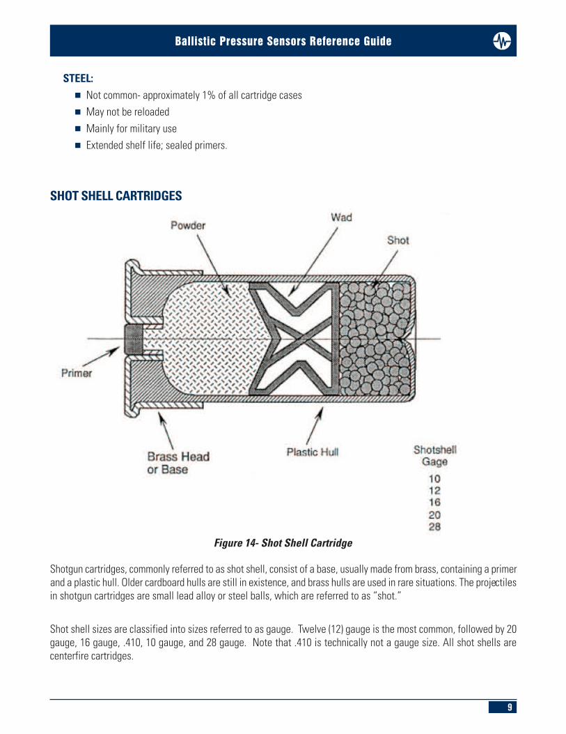
Shotgun cartridges, commonly referred to as shot shell, consist of a base, usually made from brass, containing a primerand a plastic hull. Older cardboard hulls are still in existence, and brass hulls are used in rare situations. The projectilesin shotgun cartridges are small lead alloy or steel balls, which are referred to as “shot.”
Shot shell sizes are classified into sizes referred to as gauge. Twelve (12) gauge is the most common, followed by 20gauge, 16 gauge, .410, 10 gauge, and 28 gauge. Note that .410 is technically not a gauge size. All shot shells arecenterfire cartridges.
Figure 14- Shot Shell Cartridge

10
Ballistic Pressure Sensors Reference Guide
SENSOR DIAPHRAGM DESIGNSVarious sensor diaphragms are used in the PCB® pressure sensor product line, depending on the ballistic designrequirements. Some are illustrated in Figures 15 through 17 below.
FLAT INTEGRAL, MACHINED DIAPHRAGM (see Figure 15 ):This type of diaphragm is machined into the sensor end cap. It offers a more rigid structure enabling it to withstandhigh-pressure (100K psi) repetitive cycling. Utilized when extended sensor life is desired. This thick (0.010 - 0.018 inch)diaphragm can be supplied with a flame sprayed ceramic coating which reduces thermal baseline undershoot andalso protects the sensing surface against the erosive effects of the blast. This diaphragm configuration is used on various PCB models, including Models 109C11, 109C12, 119B, 119B02, 119B11,119B12, M165A01, and 165B02.
CONFORMAL INTEGRAL, MACHINED DIAPHRAGM (see Figure 16 ):Identical characteristics as the Flat Integral type, except Conformal Integral does not require any ceramic coating, as it is notsubjected to temperature and/or blast. This is the diaphragm configuration for PCB Series 117Bx Conformal Pressure Sensors.
Figure 15- Flat Integral Machined Figure 16- Conformal Integral Machined

11
Ballistic Pressure Sensors Reference Guide
CONFORMAL BALLISTIC PRESSURE SENSORSThe conformal pressure sensor (see Figure 18), designed in cooperation with members of SAAMI (Small Arms andAmmunition Manufacturers Institute, is intended for semi-permanent installation in a test barrel for rapid-fire productiontesting of ammunition. It incorporates a curved diaphragm machined to match a specific gun chamber diameter andtaper at a predetermined location. Installed in a test barrel, the diaphragm can be looked at as an integral piston thatacts on the quartz sensing element due to the exploding gas pressure generated in the cartridge. It has no effect onthe operation of the barrel or the measurement process.
The conformal sensor shown in Figure 17 consists of an integral diaphragm with a specific curvature machined ontoit. Diaphragm body diameter is made in two sizes: 0.194 inch, and 0.248 inch.A captivated floating clamp nut rotates independently from the sensor body, allowing the sensor to be mounted whilemaintaining alignment of the curvature of the diaphragm to the chamber.
Figure 17- Series 117Bx Conformal Ballistic Pressure Sensor

12
Ballistic Pressure Sensors Reference Guide
A removable alignment guide facilitates independent alignment of the curvature. The alignment pin has a small venthole to allow close diameter installation.
A set of nine (9) spacers, with thickness from 0.010 to 0.018 inch (0.001 inch increments) compensates for variationin tolerances of the machined mounting hole depth. This spacer set facilitates the flush mounting of the diaphragmto within a tolerance of 0.001 inch.
Figure 18 below shows the conformal sensor without the alignment guide.
Figure 18- Series 117Bx Conformal Sensor, Without Alignment Guide

13
Ballistic Pressure Sensors Reference Guide
The curvature machined onto the diaphragm corresponds to the chamber diameter at a specific location forward of thebolt face. It is machined to correspond directly to the two flats machined onto the welded collar, at the connector endof the sensor.
Because the sensor location varies for different cartridges, the same PCB Model 117Bx conformal sensor is sometimesused for more than one caliber. For example, PCB Model 117B22 conformal sensor has a curvature of 0.494 inchdiameter and may be used on 7mm Remington Mag., .264 Winchester Mag., 3.00 Winchester Mag., .338 WinchesterMag., 45-70 Government, and .458 Winchester Mag. calibers, at their respective locations.
Please contact PCB for model numbers for various calibers.
The curvature machined onto the diaphragm is generally a straight (90° to body) cut. For a particular caliber, thechamber may be machined with a severe taper on the diameter. This taper must also be machined onto the diaphragmcurvature. Figure 19 shows an example of the taper.
Any chamber that has a taper of 0.020 inch on diameter or greater has the taper machined onto the conformal sensor.To indicate the proper mounting direction, a yellow dot is placed onto the collar. This dot should always be locatedtoward the muzzle or case mouth end. All sensors, including curvatures without tapers, have this yellow dot formaintaining consistency in mounting.
Figure 19- Centerfire Rifle Series 117Bx Conformal Sensor, Without Alignment Guide

14
Ballistic Pressure Sensors Reference Guide
The cartridge case of an ammunition round is intentionally made smaller in diameter than the chamber to facilitateinstallation into all of the same caliber chambers, regardless of the manufacturer and/or tolerance size (see Figure 20 ).
The gas pressure generated by the burning powder builds up to a peak value (typically in 100 to 200 micro-seconds)and outward in all directions inside the case. This expands the case outwards tightly against the chamber. The softer(annealed) neck area expands easily, forming a pressure seal at the case mouth. The harder body area expands due tothe internal pressure, and then springs back after the pressure is gone, allowing extraction of the fired case.
Note that the case itself does not have enough strength to hold this pressure. It will expand outward until constrainedby the chamber around the circumference, and at the bolt face at the rear of the case. The cartridge case now forcesitself onto the diaphragm of the sensor, creating a pressure input to the sensor.
Since the diaphragm of the sensor is insulated from the direct blast effects by the cartridge case itself, the sensor'slife is greatly extended. There are also no thermal transients to affect the pressure sensor output.
Once properly installed, the sensor need not be removed, except for routine recalibration.
Figure 20- Series 117Bx Conformal Sensor

15
Ballistic Pressure Sensors Reference Guide
A small diaphragm diameter (0.194 inch) version of PCB Model 117Bx is used for cartridge cases having a curvatureof 0.350 inch diameter or less. This sensor size is usually associated with .22 caliber ammunition.
The small diameter conformal is not used exclusively for rimfire. It may also be used on other smaller sized calibercenterfire ammunition.
Rimfire calibers are .22 short, .22 long rifle, .22 Winchester Rimfire, .22 Winchester Magnum Rimfire, and .22 long rifle shot.
Rimfire cartridges are fired by a firing pin striking the rim of the cartridge. These are relatively low-pressure cartridges,typically generating less than 15K psi.
Figure 21- Rimfire Series 117Bx Conformal Sensor, 0.194 inch dia. Diaphragm

16
Ballistic Pressure Sensors Reference Guide
Centerfire pistol and revolver cartridges usually use the larger (0.248 inch) diameter diaphragm and may also (butrarely) use the smaller (0.198 inch) diameter diaphragm.
The conformal sensor is generally located slightly behind the heel of the bullet, as shown in Figure 22. Location isusually determined by SAAMI or dictated by the customer.
Pressures generated in these cartridges are usually 10K to 45K psi.
Centerfire cartridges are fired by a firing pin striking the centrally located primer.
Figure 22- Centerfire Pistol & Revolver Series 117Bx Conformal Sensor

17
Ballistic Pressure Sensors Reference Guide
Centerfire rifle cartridges almost always use the larger (0.248 inch) diameter diaphragm, and may also (but rarely) usethe smaller (0.198 inch) diameter diaphragm.
The conformal sensors (on the necked-down cartridges) are located 0.175 inch from shoulder and sidewall junction.This is usually determined by SAAMI or dictated by the customer.
Pressures generated in these cartridges are generally 20k to 60k psi.
Centerfire cartridges are fired by a firing pin striking the centrally located primer.
Figure 23- Centerfire Rifle Series 117Bx Conformal Sensor, 0.248 inch dia. Diaphragm
18
Ballistic Pressure Sensors Reference Guide
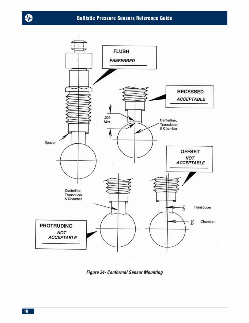
Figure 24- Conformal Sensor Mounting
19
Ballistic Pressure Sensors Reference Guide
Preparation of the mounting port for a conformal sensor is very important. As illustrated in Figure 24, the centerlinelocation from left to right must be maintained. Not only will the protruding sharp edge of a diaphragm cut into brass,but it will also affect the output of the sensor.
Installation depth of the sensor into a mounting port is equally important. A protruding sharp edge of a diaphragm willcut into brass, and will also affect the output of the sensor.
A recess of 0.002 inch maximum is permitted. Greater recess may rupture brass, and may prevent the case from beingextracted from the chamber. A flush co-planar mounting is accomplished by selecting one or more of the spacer(s)supplied.
OTHER BALLISTIC PRESSURE SENSOR CONFIGURATIONS
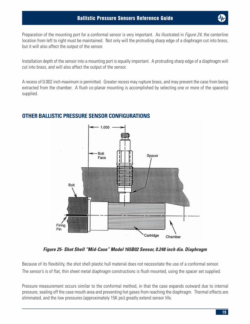
Because of its flexibility, the shot shell plastic hull material does not necessitate the use of a conformal sensor.The sensor’s is of flat, thin sheet metal diaphragm constructionc is flush mounted, using the spacer set supplied.
Pressure measurement occurs similar to the conformal method, in that the case expands outward due to internalpressure, sealing off the case mouth area and preventing hot gases from reaching the diaphragm. Thermal effects areeliminated, and the low pressures (approximately 15K psi) greatly extend sensor life.
Figure 25- Shot Shell “Mid-Case” Model 165B02 Sensor, 0.248 inch dia. Diaphragm

20
Ballistic Pressure Sensors Reference Guide
The integral diaphragm style sensor shown in Figure 26 uses a shoulder seal made of stainless steel to seal at high-pressure (100k psi to 120k psi).
Mounting torque on this type of sensor is relatively high, 20-25 foot pounds. Consequently, precise mounting holepreparation is required. The use of a ceramic-coated diaphragm aids in thermal shock protection. The sensor shouldbe removed periodically and the passage ports should be cleaned.
Figure 26- Shoulder Seal Ballistic Sensor Series 109, 119 with Ceramic Coated Diaphragm

21
Ballistic Pressure Sensors Reference Guide
Figure 28- Centerfire Rifle Case Mouth Sensor Series 109, 119 Shoulder Seal
Figure 27- Centerfire Rifle Mid-Case Sensor Series 109, 119 Shoulder Seal
OTHER BALLISTIC PRESSURE SENSOR MOUNTING TECHNIQUESUsing a sensor at the mid-case location has many drawbacks. First, the cartridge case (live round) must be drilledthrough one wall. Tape is placed over this opening to prevent powder from pouring out. When inserting into chamber,the drilled hole and sensor port must be aligned with each other.
Upon firing, hot gases are allowed to enter this passage and go directly onto the sensor diaphragm. This can resultin thermal shock to the sensor and erosion of the diaphragm. Also, the passage has to be cleaned out periodically.
CASE MOUTH SHOULDER SEAL (see Figures 28 ):
Using sensors at these locations presents challenges. However, one advantage over a mid-case location is that thesensor port does not have to be aligned with a drilled cartridge case. The same thermal and diaphragm erosion issuesremain, and the passage has to be cleaned out periodically.
This type of mounting is used more often than the mid-case mounting method. PCB Series 109 and 119 sensors aretypically used for measurements at these locations.

22
Ballistic Pressure Sensors Reference Guide
CONFORMAL SENSOR CALIBRATION
In order to accurately calibrate PCB Series 117Bx Conformal Sensors, it is necessary to use unfired cases with a primerin place. PCB’s Model 090Bx Calibration Adaptor simulates the chamber, and is made for each specific caliber. The090Bx adaptor consists of a pressure chamber, cartridge case retaining nut, pressure chamber adaptor, and an adaptorretaining nut (see Figure 29).
The PRESSURE CHAMBER has the specific caliber chamber configuration reamed into it, along with thesensor/alignment mounting hole(s). This is used to accept a cartridge case and to hold the calibration pressure withthe conformal sensor.
The CARTRIDGE CASE RETAINING NUT has a 3/4-16 external thread and a hexagon head. This is used to hold thecartridge case in place while being pressurized. On occasion, it is necessary to use this type of retaining nut with ano-ring to facilitate sealing at the primer area. This is a necessity with cartridge cases made from aluminum alloy.
The PRESSURE CHAMBER ADAPTOR has a high-pressure input end configuration that is identical to the 3/8-24 externalthread and 7/16 hex body found in Series 119 pressure sensors. This end is the same for all adaptors. The oppositeend varies with each caliber, and is grooved for an o-ring that inserts directly into the cartridge case and seals thepressure inside the case.
Figure 29- Conformal Calibration Adaptor Series 090Bx

23
Ballistic Pressure Sensors Reference Guide
The ADAPTOR RETAINING NUT has a 3/4-16 internal thread and a round knurled body. This is used to hold the pressurechamber adaptor into the cartridge case while being pressurized. When calibrating a sensor using steel cases, it isnecessary to use the retaining nut with the hexagon body to facilitate assembly of the pressure chamber adaptor intothe steel cartridge case.
Series 117Bx Conformal Sensors are installed into the empty pressure chamber, using the spacer set supplied, so thatthe curvature of the sensor is flush with the chamber curvature.
The cartridge case requires the case mouth to be chamfered to allow easy entry of the o-ring on the pressure chamberadaptor. The use of a 90° countersink is recommended.
The cartridge case is inserted into the pressure chamber, and the cartridge case retaining nut is installed. Theunthreaded portion “bottoms out” on the bolt face surface of the pressure chamber.
The o-ring on the pressure chamber adaptor is lubricated with silicone grease or hydraulic oil and inserted into pressurechamber opening.
The adaptor retaining nut is installed over the pressure chamber adaptor, and is hand-tightened.
Figure 30- Series 090Bx Conformal Calibration Adaptor- Assembly and Use

24
Ballistic Pressure Sensors Reference Guide
The calibration adaptor is then installed into a high-pressure port, and the following is performed:
n Pressure is applied slowly, starting at the lowest level n Pressure is needed to expand the case until sensor output is recorded. This is the offset. n Data is recorded at five pre-determined, incremental pressure levels, up to the maximum n Pressure is released, and the cartridge case is discarded
A new chamfered cartridge case is installed
n Above steps are repeated for 10 cartridge cases n Average of 10 rounds is taken at each pressure point
Figure 31- Conformal Calibration System

25
Ballistic Pressure Sensors Reference Guide
A typical high-pressure calibration system is shown in Figure 31.
Calibration of a PCB Series 117Bx Conformal Sensor is accomplished by mounting the sensor in the same manner asit is to be used in the gun. The high-pressure pump and appropriate adaptor used in calibration allows the calibrationadaptor to be closely coupled to the pump, reducing volume and eliminating the need for high-pressure lines.
The calibration is performed by comparing the sensor charge output to the known static input pump pressure.
An example of a calibration plot for a conformal sensor is shown in Figure 33. Calibration of a conformal sensor usingthe brass, aluminium, or steel cartridge cases shows that the slope of the sensor does not go through zero. This is dueto the fact that a few thousand psi is required to expand outward the relaxed cartridge case to contact the chamberwall and Conformal Sensor. This pressure is referred to as the offset. The offset will vary per caliber, material thickness,and material hardness.
A conformal pressure sensor may also be oil calibrated (without using the calibration adaptor and cartridge case) ifeither, or both, are not available. An oil-only calibration will establish linearity, but will not establish the sensitivityaccuracy required for use as a conformal pressure sensor (see Figure 34 ).
Figure 32- Conformal Calibration System- High-Pressure Pump Detail

26
Ballistic Pressure Sensors Reference Guide
Figure 33- Calibration Plot for a Conformal Sensor

27
Ballistic Pressure Sensors Reference Guide
Figure 34- Standard Oil Calibration Plot Through Zero

Sensors and Instrumentation For All Your Applications
Toll-Free in USA 888-684-0014E-mail [email protected]
Toll-Free in USA 800-828-8840E-mail [email protected]
Toll-Free in USA 800-959-4464E-mail [email protected]
Toll-Free in USA 866-684-7107E-mail [email protected]
Please see these PCB Piezotronics catalogs for your other Aerospace & Defense applications:n Flight Testn Explosive, Gun and Impact Testing
3425 Walden Avenue, Depew, NY 14043-2495 USAToll-Free in USA 866-816-8892 n Fax 716-684-0987 n E-mail [email protected]
n Ground Testn OEM Capabilities
For our complete line of sensors, see our Test & Measurement Catalog.
Toll-Free in USA 800-860-4867E-mail [email protected]
Toll-Free in USA 888-258-3222E-mail [email protected]
Ballistic Pressure Sensors Reference Guide
3425 Walden Avenue, Depew, NY 14043-2495 USAToll-Free in USA 866-816-8892
24-hour SensorLineSM 716-684-0001 Fax 716-684-0987 E-mail [email protected]
Web Site www.pcb.comAS9100 CERTIFIED n ISO 9001 CERTIFIED n A2LA ACCREDITED to ISO 17025
© 2014 PCB Group, Inc. In the interest of constant product improvement, specifications are subject to change withoutnotice. PCB, ICP, Modally Tuned, Spindler, Swiveler and TORKDISC are registered trademarks of PCB Group. SoundTrackLXT, Spark and Blaze are registered trademarks of PCB Piezotronics. SensorLine is a service mark of PCB Group. All othertrademarks are properties of their respective owners.
AD-BALLISTICPRESSUREGUIDE-0614 Printed in U.S.A.
The Aerospace & Defense division of PCB Piezotronics serves the Turbine Engine,Helicopter Health and Usage Monitoring (HUMS), Ground Vibration Test, Flight Test,Wind Tunnel Test, Fuze/Safe and Arm, Spacecraft and Aerospace Systems designand development communities with sensors and associated signal conditioning formeasurement of acceleration (vibration, shock and rigid body); acoustics; pressure;force; strain; and torque. Sensor technologies employed include piezoelectric,piezoresistive (both strain gauge and MEMS) and variable capacitive (both MEMSand microphone). Manufacturing operations are certified to AS9100:2004 and ISO9001:2000, with calibration procedures accredited by A2LA to ISO 17025. Productscan be manufactured to meet specific aerospace environmental standards, withprogram design requirements to meet RTCA-DO-160 and MIL-STD-810, and lowoutgassing designs available for specific applications.
Visit www.pcb.com to locate your nearest sales office