background and rationale document€¦ · · 2016-03-02background and rationale document....
TRANSCRIPT

BACKGROUND AND RATIONALE DOCUMENT
PROPOSED PETROCHEMICAL INDUSTRY STANDARD (for selected contaminants)
UNDER ONTARIO’S LOCAL AIR QUALITY REGULATION
February 2016
Ontario Ministry of the Environment and Climate Change Environmental Sciences and Standards Division
Standards Development Branch The information contained in this document is confidential and proprietary to the Government of Ontario. Unauthorized distribution or use of this document or the information contained herein is strictly prohibited.

Copyright & Disclaimer The Government of Ontario reserves the right to make changes in the information contained in this publication without prior notice.
2016 Government of Ontario. All rights reserved. Other product or brand names are trademarks or registered trademarks of their respective holders. This document contains proprietary and confidential information about Government of Ontario, disclosure or reproduction is prohibited without the prior express written permission from Government of Ontario.
MOECC – Standards Development Branch February 2016

Executive Summary The primary objective of a technical standard, under Ontario’s Local Air Quality Regulation (the regulation), is to include requirements for the implementation of best available air pollution control. This will lead to modernization of operations with respect to minimizing air pollution. In practical terms, a technical standard provides a prescriptive set of air pollution control requirements that focus on key contributors to off-site concentrations of priority air toxics. The purpose of this proposed technical standard is to identify and implement best available controls to minimize air emissions of benzene and 1,3 butadiene from Ontario petrochemical facilities. If approved, the proposed Petrochemical – Industry Standard would be one of three compliance approaches to minimize air emissions of the above-noted two contaminants. There are four petrochemical facilities in Ontario (Imperial Oil - Sarnia; Lanxess – Sarnia, Nova – Corunna and Styrolution - Sarnia). Each of these facilities would either register to comply with a technical standard; request a site-specific standard; or comply with the air standards for these two contaminants. The process to develop a proposed petrochemical technical standard includes a combination of analysis and consultations with industry stakeholders and community partners. This effort has been on-going since May 2013 and involved the following steps:
• A review of the available Emission Summary and Dispersion Modelling (ESDM) reports for each Ontario petrochemical facilities with the objective of assessing benzene and 1,3 butadiene air emission estimates and dispersion modelling.
• Completion of a dominant source analysis; on-site confirmatory monitoring and a multi-source atmospheric dispersion modelling review of both industrial and transportation air emissions of benzene and 1,3 butadiene. This work contributed to the goal of identifying the most significant contributors to off-site impacts for the target contaminants.
• Technology benchmarking to identify best available methods and air pollution control requirements for petrochemical facilities in other leading jurisdictions. In this case, federal rules from the United States Environmental Protection Agency (US EPA) and related requirements from key states such as California, Louisiana and Texas, were an important point of comparison.
• Consultation with industry stakeholders; liaison with representatives of regulators in other jurisdictions; and co-hosting with the Canadian Fuels Association and Air & Waste Management Association a monitoring conference in November 2014 all contributed towards identifying lessons-learned from the implementation of similar requirements in the United States. This was an important step towards developing the proposed technical standard for petrochemical facilities in Ontario.
• Liaison with community groups and First Nations to provide information and obtain input towards development of the proposed technical standard
• Collaboration with legal services staff and representatives from other Ministry of the Environment and Climate Change (the “Ministry”) departments including district and regional staff; and technical experts within the Environmental Approvals Branch, Environmental Monitoring & Reporting Branch, and Air Policy & Climate Change Branch was an important aspect of ensuring a balanced and enforceable proposed technical standard.
An external technical working group was formed in May 2013 with the objective of providing inputs during the development of the proposed technical standard. The representatives of the MOECC – Standards Development Branch February 2016 ii

Aamjiwnaang1 and Walpole Island First Nations (WIFN) were invited to participate in the working group meetings starting in 2014. An additional community member also joined the group in 2015. The external technical working group provided valuable guidance and assistance towards the objective of achieving a balance of interests. However, a consensus amongst all participants was not possible with respect to the specific level of control that should be included in the proposal. Summary of Stakeholder and First Nation Input and Concerns
In general, industry representatives emphasized the importance of focusing on the most significant sources; considering lessons-learned from implementation of U.S. air pollution rules; and ensuring that the development of proposed requirements consider cost effectiveness and the cumulative effect of cost pressures from multiple and simultaneous environmental initiatives. First Nations representatives have expressed concerns with the process to develop a technical standard proposal (e.g., a lack of capacity and corresponding funding to allow First Nations to contribute substantively); an inability to review information related to the dominant source analysis; and emphasized the need to consider cumulative effects from multiple facilities, multiple contaminants and exposure pathways; and to consider a historical pattern of exposures. The Ministry has responded to these concerns by hiring a jurisdictional expert to provide information to both the Ministry and First Nations with respect to the most stringent air pollution requirements for US petroleum refineries (many of these requirements are similar to petrochemical facilities). This information was considered in the development of the proposed technical standard and in assessing “lessons-learned” and cost effectiveness aspects, as requested by the industry representatives. Chapter 7 of this report includes more information with respect to stakeholder and First Nations input and concerns. Conclusions
Current information with respect to air emissions and an analysis in identifying the dominant contributors to point of impingement concentrations of benzene suggest that a focus within the proposed technical standard on storage vessels, equipment leaks, wastewater treatment operations and product loading is reasonable. Additional requirements for property-line monitoring of benzene and 1,3 butadiene is anticipated to provide important information with respect to ensuring the success of the proposed rules and identifying additional emission reduction opportunities, if needed.
Although Ontario petrochemical facilities have been implementing voluntary efforts to limit air emissions of volatile organic compounds (VOCs) such as benzene and 1,3 butadiene. A jurisdictional review has determined that current air pollution control practices to limit benzene air emissions from petrochemical facilities in Ontario are lagging behind the requirements in the United States. The jurisdictional review suggests that the U.S. Federal and State requirements provide a reasonable basis to develop air pollution control requirements for Ontario petrochemical facilities. For 1, 3 butadiene, the proposed technical standard should focus on the control of process fugitives from equipment leaks based on the dominant source analysis, in addition to requiring the property-line ambient monitoring. Specific requirements and phase-ins have been developed based on an intention to balance the need for new air pollution control requirements with cost effectiveness. Phase-in of requirements
1 The Aamjiwnaang First Nation is adjacent to three of the four petrochemical facilities and within a few kilometres of a fourth facility. There are also a number of petroleum refineries nearby. MOECC – Standards Development Branch February 2016 iii

over a period of time is anticipated to facilitate appropriate planning, engineering and construction and to reduce implementation costs. Ministry work in 2015 and 2016 was completed at a measured but relatively expeditious pace. The intent was to complete the work so that benzene emission reductions and regulatory certainty could be achieved as soon as possible. However, it is anticipated that additional effort by the Ministry is needed to engage and build trust with the Aamjiwnaang and Walpole Island First Nations.
Recommendations to Address First Nations Concerns and Path Forward
It is proposed that the ministry will continue to work with industry stakeholders and community partners as the new air pollution requirements are implemented. In particular, due to the proximity of many of the petroleum refining and petrochemical facilities along with ongoing concerns from the communities themselves, a collaborative approach with the Aamjiwnaang First Nation and the Walpole Island First Nation will be undertaken to verify air quality improvements and to identify additional air pollution control requirements as necessary. These implementation efforts are anticipated to culminate in a review of the petroleum refining and petrochemical sector requirements in 2023.
Summary of Proposed Rules and Next Steps
Table ES-1 on the following pages provides a summary of the requirements in the proposed technical standard for petrochemical sector. Chapter 9 of this report provides a more detailed summary of the proposed requirements. The proposed Petrochemical - Industry Standard will be posted in the Environmental Bill of Rights registry for a 90-day public consultation period. Further discussions with stakeholders and First Nations partners are also anticipated at the end of this formal public consultation period.
MOECC – Standards Development Branch February 2016 iv

Table ES-1: Summary of Proposed Recommended Requirements
Source/Aspect
Description and Implementation Timelines
Applicable Storage Vessels
Applicability: At least 75 cubic metres capacity; and stores liquid with at least 2% by weight benzene. Starting January 1, 2018: • All new applicable storage vessels must be equipped with internal floating roof (IFR),
external floating roof (EFR) or closed vent and control system requirements that comply with the latest US federal rules.
• Optical gas imaging leak inspection requirements for both new and existing applicable storage vessels.
Phase-in Between 2020 and 2029: • All existing applicable storage vessels must be retrofitted with IFR, EFR or closed
vent and control system (except for existing applicable storage vessels that are already equipped with IFR).
Wastewater Treatment Operations
API Separators: install by January 1, 2019 IFR, EFR or closed vent and control or monitor (starting July 1, 2017) ambient air or inlet/outlet wastewater for benzene. Drains and Junction Boxes: implement by January 1, 2019 air pollution control plans for all process drains with junction boxes within 200 metres of the property-line or monitor for benzene in wastewater.
Product Loading
Applicability: For product containing 2% by weight benzene or more; truck and railcar loading racks with product throughputs above 14 million litres per year; and marine vessel loading with three-year rolling average throughputs greater than 1.6 billion litres of product. Starting January 1, 2017: must record product throughput for truck and rail loading racks and marine vessel terminals. Require closed vent and air pollution control within 18 months of recording above the throughput thresholds.
Property-Line Ambient
Monitoring
Applicability: For all facilities registering to the technical standard. Ambient monitors are measuring benzene for at least 12 locations at or nearby to the property-line. Starting January 1, 2018: the monitoring must be based upon a plan approved by the Ministry and include two-week duration samples. A baseline of three years of monitoring data must be developed for each monitor. If, in subsequent years, the benzene monitoring results at any monitor are statistically significantly higher than the baseline then the facility must notify a provincial officer as soon as practicable and within six months submit details of the increase; an explanation of the possible causes; and a plan to prevent any future statistically significant increases above the baseline. A new baseline shall be re-determined every year after the third year and the re-determined baseline becomes applicable for a monitor if the average of the new data is less than the average of the previously determined baseline.
Note: This table provides a summary only. For details see the Environmental Bill of Rights (EBR) registry proposal to obtain a legal draft of the proposed technical standard. If there is any discrepancy between this summary and the legal draft on the EBR registry then the legal draft is deemed to be the correct version.
MOECC – Standards Development Branch February 2016 v

Table ES-1: Summary of Proposed Recommended Requirements continued
Source/Aspect
Description and Implementation Timelines
Equipment Leaks
Leak-
Detection- and-Repair
(LDAR)
Applicability: for components in contact with fluid that contains 2% by weight benzene or more. Exempt components include valves with a nominal diameter less than 1.875 centimetres; components that are unsafe to monitor and some pumps. A leak is defined as greater than 1,000 parts per million by volume volatile organic compounds (VOC). Component leak surveys starting January 1, 2018: must complete a survey every 4 months (or at least once per year if the percentage of leaking valves is less than 1%). One survey per year must be completed using a method specified in the proposed technical standard (i.e., similar to US Method 21); and the other surveys in a year may be completed using an optical gas imaging method. Audit of component leak surveys: it is a contravention if a compliance audit determines that the percent leaking components is more than 50% greater than what was found in the original survey. Leak repair timeframes starting January 1, 2020: leak repairs must be completed within specified time-frames, beginning January 1, 2020. Delay of repair list: Delaying the repair of a component until the next process unit shutdown is allowed if the combined total of leaks on delay of repair (for components in 50% or greater service) is less than 250,000 parts per million by volume as benzene.
Air Pollution Control Devices
Applicability: to air pollution control devices that are used for the purposes of reducing benzene air emission requirements associated with the proposed technical standard. Starting January 1, 2018: Benzene or VOC emission limits for air pollution control devices. Must source test every two years. For flares used as air pollution control devices, must comply with latest US federal requirements by January 1, 2023.
Record-keeping,
Reporting, Complaint
Response; and Web-Site
Information Sharing
Record-keeping starting January 1, 2018: for applicable storage vessels; wastewater treatment operations; product loading; leak detection and repair; property-line monitoring; and air pollution control performance monitoring. Reporting requirements: annual report to summarize above-noted records; and submission, to the District Manager, of a delay-of-repair-report every six months. Web-site reporting of property-line measurements: property-line benzene monitoring results; annual reports related to ambient monitoring; and actions taken to address any statistically significantly higher monitoring results must be posted to the facility web-site; Complaint response requirements: prompt action and record-keeping for public complaints.
Note: This table provides a summary only. For details see the Environmental Bill of Rights (EBR) registry proposal to obtain a legal draft of the proposed technical standard. If there is any discrepancy between this summary and the legal draft on the EBR registry then the legal draft is deemed to be the correct version.
MOECC – Standards Development Branch February 2016 vi

Table of Contents Executive Summary ...........................................................................................................................ii 1. Introduction .................................................................................................................................... 1 2. Description of the Ontario Petrochemical and Synthetic Resins Industry ............................... 5
2.1 Ontario Industry Overview ................................................................................................ 5 2.2 General Description of the Petrochemical Manufacturing Process ................................ 6
3. Dominant Source Analysis for Benzene and 1,3 Butadiene Air Emissions ............................... 8
3.1 Dominant Source Analysis Methodology ............................................................................... 8 3.2 Summary of Results ................................................................................................................. 9
4. Jurisdictional Review ................................................................................................................... 11
4.1 Canada – CCME Guidelines ................................................................................................. 11 4.2 U.S. Federal Requirements for Air Pollution Control at Petrochemical Facilities .......... 13 4.3 Review of US “Title V” Operating Permit Program for Major Sources .......................... 22 4.4 U.S. State Requirements for Air Pollution Control at Petrochemical Facilities .............. 26
4.4.1 California Requirements for Air Pollution Control ..................................................... 26 4.4.2 Louisiana .......................................................................................................................... 33 4.4.3 Texas ................................................................................................................................. 34
4.5 Other Relevant Documents ................................................................................................... 38 4.6 Sarnia Monitoring Workshop (November 5-6, 2014) ......................................................... 46
5. Summary of Current Methods to Minimize Emissions of Benzene and 1,3 Butadiene from Dominant Sources ............................................................................................................................ 50 6. Analysis of Any Gaps Between Current Methods in Ontario and Other Jurisdictions ........ 52 7. Consideration of Stakeholder and Community Feedback ....................................................... 53 8. Consideration of the Ministry’s Statement of Environmental Values .................................... 65 9. Summary of Conclusions and Recommendations for a Proposed Petrochemical Industry Standard ............................................................................................................................................ 66 Appendix A: Bibliography Appendix B: Summary of Stakeholder and Community Meetings
MOECC – Standards Development Branch February 2016 vii
1. Introduction Ontario protects air quality through a comprehensive air management framework that includes regulations, targeted programs and partnerships with other jurisdictions to address sources of air pollution. Ontario’s local air quality regulation (O. Reg. 419/05: Air Pollution – Local Air Quality herein “Regulation”) works within the province’s air management framework by regulating air contaminants released into communities by various sources, including local industrial and commercial facilities. The regulation aims to limit exposure to substances released into air that can affect human health and the environment, while allowing industry to operate responsibly under a set of rules that are publicly transparent. Through the Local Air Regulation, we are facilitating new investments in air pollution controls and modernization at Ontario facilities to better protect air quality. Under the regulation, industry can implement one of three compliance approaches, each designed to manage the risks associated with a facility’s air emissions:
• Meet the provincial air standard; • Request and meet a site-specific standard; or • Register and meet the requirements under a technical standard (if available).
All three approaches are allowable under the regulation. Why are there three compliance approaches? All industrial and commercial facilities must comply with the local air quality regulation. Air standards are a key part of the regulation. They are used to evaluate the contribution of a contaminant to air from a regulated facility. New or updated air standards are phased in to give industry reasonable time to plan to meet them or to request another compliance approach (i.e., through a site-specific standard or sector-based technical standard). Since the provincial air standards are set based on science, they may not be achievable by a facility or a sector due to unique technical or economic limitations. Instead of making the air standard less stringent, the regulation allows facilities or sectors to exceed the air standard as long as they are working to reduce their air emissions as much as possible with technology-based solutions and best practices. The Ministry closely oversees their progress using a framework for managing risk that was developed in cooperation with public health units in Ontario and other stakeholders. Some facilities may never meet the air standard and instead will be regulated under one of the other compliance approaches. The Technical Standard Compliance Approach A technical standard is a technology-based solution designed for two or more facilities in a sector that are not able to meet an air standard due to technical or economic limitations. This approach can include technology, operation, monitoring and reporting requirements that are relevant to day-to-day activities at a facility. Once the technical standard is published, any facility in the sector (that may or may not meet the air standard) may apply to be registered under this compliance approach. Such registration would involve a posting on the Environmental Registry and may involve a public meeting. The goal is to have a more efficient tool to better manage air emissions in the sector and reduce overall exposure from various industrial and commercial facilities.
MOECC – Standards Development Branch February 2016 Page 1

The technical standards are published under the authority of section 38 of the Regulation. The technical standards publication specifies the classes of facilities and the contaminants that the technical standard applies to and the steps and time periods for compliance. There are two types of technical standards under the Regulation: industry standards that regulate all sources of a specified contaminant(s) within an industry sector; and equipment standards that address a specific type of equipment or source of contaminant, but may apply to one or multiple industry sectors. A facility may be registered for an industry standard, an equipment standard or a combination of industry standard and equipment standard. If the technical standards published address all sources of a contaminant from a facility, the registered facility is exempt from the relevant air standard – and instead must abide by the requirements of the technical standard. If the published technical standards do not address all sources of a contaminant from a facility, then only certain sources of the contaminant may be excluded from the Emission Summary and Dispersion Modelling (ESDM) report. A facility can choose which contaminants it registers for. A facility must still meet the relevant air standards for the contaminants that are emitted by the facility and not included in the technical standard, and must comply with the relevant air standards for the contaminants, within a technical standard, that a facility chooses not to register to. In the development of a technical standard, the ministry assesses all sources of a contaminant related to a North American Industry Classification System (NAICS) code, and makes a decision as to whether or not that source needs to be better controlled, monitored or managed. Development of a technical standard includes a better understanding of sources of the contaminant for that sector, benchmarking technology to address the sources of a contaminant, and consideration of economic issues. Specific requirements are included in the technical standard for those major sources that are determined to need better management or control. Timeframes are specified for implementation of the requirements.
1.1 Background
In 2011, the ministry introduced new/updated standards for nine contaminants, which included annual standards for benzene and 1,3 butadiene: these standards take effect on July 1, 2016. Representatives of the petrochemical sector have indicated to the Ministry2 - at least two or more facilities in this sector (currently comprised of four petrochemical facilities in Ontario) will be challenged to meet these new standards for benzene and 1,3 butadiene. A proposed technical standard which applies to petrochemical manufacturing may be a viable compliance approach for this sector. This rationale document provides information to support the proposal for a Petrochemical - Industry Standard. This proposal includes an assessment of emissions of benzene and 1,3 butadiene. Other contaminants emitted from a petrochemical facility were not included in this assessment. In developing this proposed Petrochemical - Industry Standard, key sources of contaminants were identified and prescribed steps and timelines are proposed to address them. A facility can also choose which contaminants it registers for.
2 Letter dated April 1, 2013 from the Chemistry Industry Association of Canada to the Minister of the Environment. MOECC – Standards Development Branch February 2016 Page 2

1.2 Purpose and Scope of a proposed Petrochemical - Industry Standard
The purpose of a proposed Petrochemical - Industry Standard is to enable facilities to demonstrate best available control of emissions of benzene and 1,3 butadiene emitted from these facilities. This proposed Petrochemical - Industry Standard is intended to apply to facilities identified as part of NAICS code 325110 (Petrochemical Manufacturing). In developing the proposed Petrochemical - Industry Standard requirements set out in this rational document, the Ministry referred to a variety of documents published by environmental regulatory agencies from Canada, the United States and Europe (see Appendix A for a list of key reference material). In summary, the requirements to be set out in a proposed Petrochemical - Industry Standard will consider all of the above information, other relevant studies undertaken by the Ministry, other publicly available information, submissions made by representatives of member companies and the Chemistry Industry Association of Canada (CIAC) to the Ministry during the technical consultation sessions, and feedback from discussions with local community members including Aamjiwnaang and Walpole Island First Nations. Question 1.2A: The ministry is also seeking input as to whether or not vinyl chloride emitted from plants that produce polyvinyl chloride resin should also be included in this proposed Petrochemical - Industry Standard. If adopted, this would include NAICS code 325210 Resin and Synthetic Rubber Manufacturing. The key sources of vinyl chloride emissions from polyvinyl chloride resin facilities are very similar to the sources of benzene air emissions from petrochemical manufacturing facilities (e.g., equipment leaks and wastewater treatment operations). However, additional requirements for vinyl chloride raw material unloading operations and minimizing the amount of residual vinyl chloride monomer in the polyvinyl chloride resin product would also be considered
1.3 Organization of Report
The purpose of this document is to provide the Ministry’s rationale and consideration of the information relevant to a proposed Petrochemical - Industry Standard. The document is structured to build upon background information and analyses to support recommendations for the proposal:
• Chapter 2 provides a description of the Ontario petrochemical and synthetic resins industry; • Chapter 3 provides analyses related to identifying sources that are dominant contributors to
point of impingement concentrations for both benzene and 1,3 butadiene; • Chapters 4, 5 and 6 compare and benchmark methods and requirements between Ontario
and other jurisdictions, to minimize air emissions of benzene and 1,3 butadiene sources; • Chapter 7 documents the consideration of stakeholder and community feedback. Also
provides a review and develops recommendations for measures to assess the performance of Ontario petrochemical facilities, and the long-term effectiveness of Petrochemical - Industry Standard in minimizing point of impingement concentrations of both benzene and 1,3 butadiene;
• Chapter 8 provides a summary of the consideration of the Ministry’s Statement of Environmental Values; and
• Chapter 9 outlines the conclusions of the analyses and consultation efforts, and summarizes the recommendations for the content of a proposed Petrochemical - Industry Standard.
MOECC – Standards Development Branch February 2016 Page 3

1.4 Authority
The Regulation provides authority to the Minister of the Environment and Climate Change to publish and amend the Technical Standards Publication entitled: “Technical Standards to Manage Air Pollution”. See sections 38 through 44 of the Regulation.
MOECC – Standards Development Branch February 2016 Page 4

2. Description of the Ontario Petrochemical and Synthetic Resins Industry
Industries in Canada (and North America) are classified according to the North American Industrial Classification System (NAICS). The chemical manufacturing subsector is captured in NAICS 325 which comprises establishments primarily engaged in manufacturing chemicals and chemical products, from organic and inorganic raw materials.
2.1 Ontario Industry Overview Within NAICS 325, there are the following sub-groups:
• Basic chemicals (NAICS 3251); • Synthetic resins, rubbers, and synthetic fibres (NAICS 3252); • Pesticides and fertilizers (NAICS 3253); • Pharmaceuticals (NAICS 3254); • Paints, coatings and adhesives (NAICS 3255); • Soaps, cleaning compounds and toilet preparations (NAICS 3256); • Other chemical products (NAICS 3259).
The relative distribution of these sub-groups in Ontario is shown in Figure 2-1. The petrochemical sector is NAICS 325110, which is the focus of this proposed Petrochemical – Industry Standard. Figure 2-1: Relative distribution of sub-groups in Ontario Petrochemical and Synthetic Resins Industry
Basic chemicals 27%
Resins and fibres 25%
Pharmaceuticals 23%
Paints and adhesives
6%
Soaps toiletries
10%
Other chemical products
9%
MOECC – Standards Development Branch February 2016 Page 5
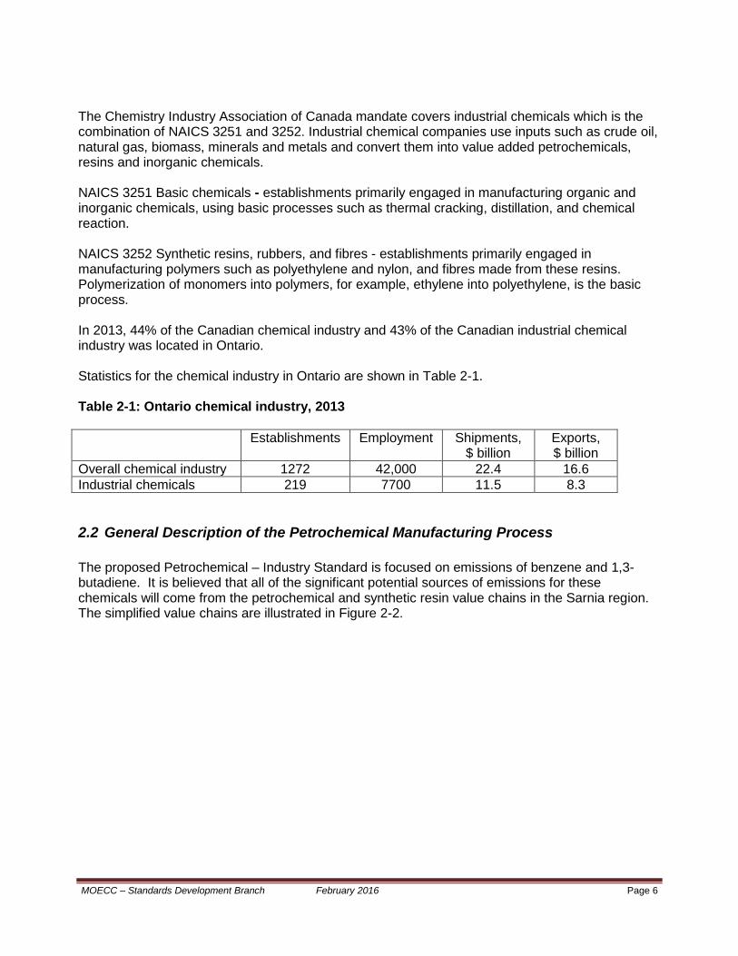
The Chemistry Industry Association of Canada mandate covers industrial chemicals which is the combination of NAICS 3251 and 3252. Industrial chemical companies use inputs such as crude oil, natural gas, biomass, minerals and metals and convert them into value added petrochemicals, resins and inorganic chemicals. NAICS 3251 Basic chemicals - establishments primarily engaged in manufacturing organic and inorganic chemicals, using basic processes such as thermal cracking, distillation, and chemical reaction. NAICS 3252 Synthetic resins, rubbers, and fibres - establishments primarily engaged in manufacturing polymers such as polyethylene and nylon, and fibres made from these resins. Polymerization of monomers into polymers, for example, ethylene into polyethylene, is the basic process. In 2013, 44% of the Canadian chemical industry and 43% of the Canadian industrial chemical industry was located in Ontario. Statistics for the chemical industry in Ontario are shown in Table 2-1. Table 2-1: Ontario chemical industry, 2013 Establishments Employment Shipments,
$ billion Exports, $ billion
Overall chemical industry 1272 42,000 22.4 16.6 Industrial chemicals 219 7700 11.5 8.3
2.2 General Description of the Petrochemical Manufacturing Process
The proposed Petrochemical – Industry Standard is focused on emissions of benzene and 1,3-butadiene. It is believed that all of the significant potential sources of emissions for these chemicals will come from the petrochemical and synthetic resin value chains in the Sarnia region. The simplified value chains are illustrated in Figure 2-2.
MOECC – Standards Development Branch February 2016 Page 6
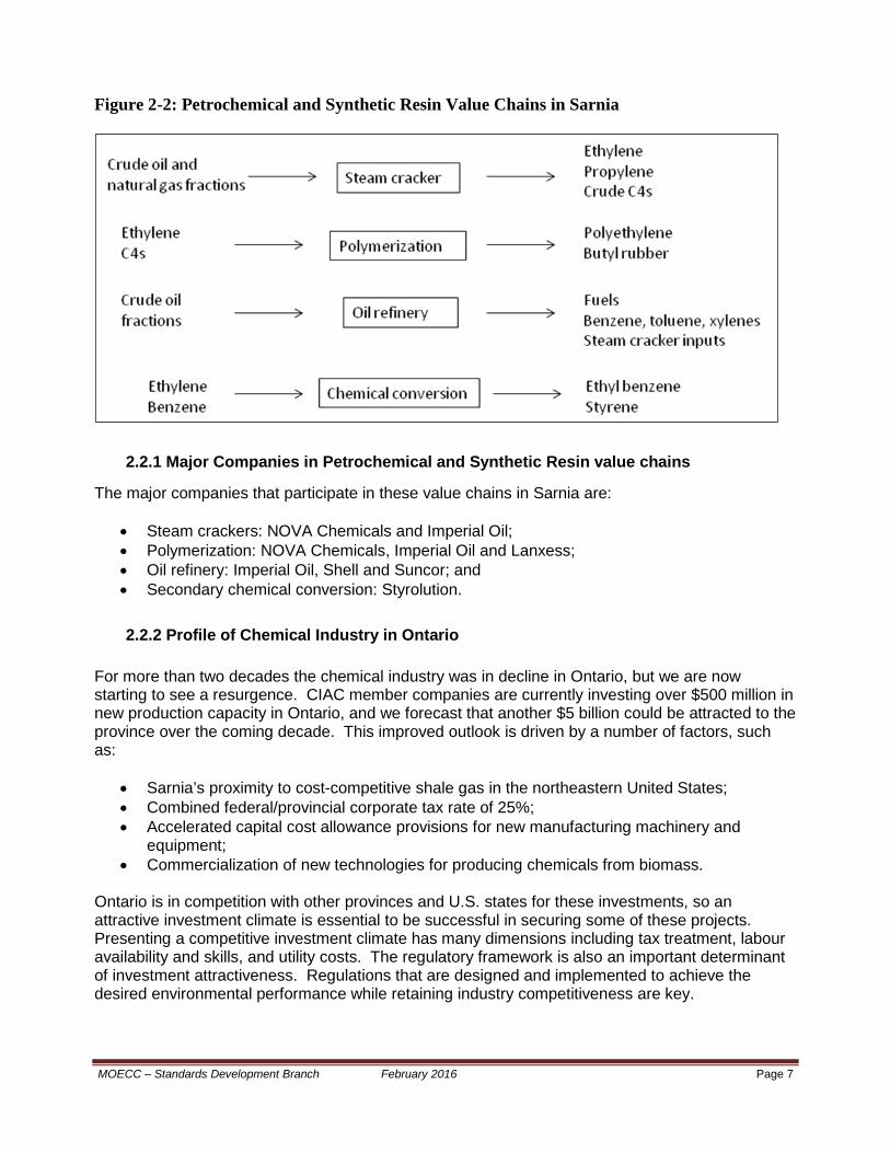
Figure 2-2: Petrochemical and Synthetic Resin Value Chains in Sarnia
2.2.1 Major Companies in Petrochemical and Synthetic Resin value chains
The major companies that participate in these value chains in Sarnia are:
• Steam crackers: NOVA Chemicals and Imperial Oil; • Polymerization: NOVA Chemicals, Imperial Oil and Lanxess; • Oil refinery: Imperial Oil, Shell and Suncor; and • Secondary chemical conversion: Styrolution.
2.2.2 Profile of Chemical Industry in Ontario
For more than two decades the chemical industry was in decline in Ontario, but we are now starting to see a resurgence. CIAC member companies are currently investing over $500 million in new production capacity in Ontario, and we forecast that another $5 billion could be attracted to the province over the coming decade. This improved outlook is driven by a number of factors, such as:
• Sarnia’s proximity to cost-competitive shale gas in the northeastern United States; • Combined federal/provincial corporate tax rate of 25%; • Accelerated capital cost allowance provisions for new manufacturing machinery and
equipment; • Commercialization of new technologies for producing chemicals from biomass.
Ontario is in competition with other provinces and U.S. states for these investments, so an attractive investment climate is essential to be successful in securing some of these projects. Presenting a competitive investment climate has many dimensions including tax treatment, labour availability and skills, and utility costs. The regulatory framework is also an important determinant of investment attractiveness. Regulations that are designed and implemented to achieve the desired environmental performance while retaining industry competitiveness are key.
MOECC – Standards Development Branch February 2016 Page 7

3. Dominant Source Analysis for Benzene and 1,3 Butadiene Air Emissions
The purpose of this analysis is to identify the sources of emissions that are the dominant contributors to point of impingement concentrations of a contaminant. The results of the analysis can be a key factor in the prioritization of air pollution control efforts; be used to eliminate lower priority sources from further review; and, correspondingly, minimize capital and operating costs.
3.1 Dominant Source Analysis Methodology
The dominant source analysis approach used to assist in the development of a proposed Petrochemical – Industry Standard for petrochemical sector involved the following basic approach that was applied to four Ontario petrochemical facilities:
• The use of the latest ESDM reports for each facility (including atmospheric dispersion modelling on an annual average basis for both benzene and 1,3 butadiene as a basis for the dominant source analysis).
• Group the air emission sources at each facility into the following five categories for both benzene and 1,3 butadiene:
• Major point sources; • Storage vessels; • Process fugitives; • Wastewater treatment systems; and • Loading sources.
• Run the atmospheric dispersion models for a large suite of off-site receptors (e.g., greater than a thousand off-site receptors for each of the four petrochemical facilities) to determine the contributions to point of impingement concentrations for each of the source groups.
• Document the results of the modelling in a spreadsheet including factors such as emission estimate data quality and parameters such as source group dispersion factor.
• Based upon the initial set of atmospheric dispersion modelling, identification of a sample of receptors that were distributed throughout the exceedence zone (i.e., due to the fugitive nature of benzene and 1,3 butadiene air emissions, the exceedence zone for contaminants was generally identified as the area between the facility fence-line and a concentration isopleth that is equivalent to their respective air standards). Depending upon the extent of the exceedence zone at each facility, a sampling of between 25 and 50 exceedence zone receptors were identified.
• Run the atmospheric dispersion models a second time but only with the exceedence zone receptors.
• Document the results of the second set of modelling including source group contribution to the point of maximum concentration and average source group contribution to point of impingement concentrations to the group of receptors within the exceedence zone.
• Due to the uncertainty of fugitive emission estimates, verification using ambient monitoring campaign in key on-site locations.
• Use the results from the above-noted modelling and monitoring components of the analysis to identify the types of sources that are the dominant contributors to the point of impingement concentrations for the relevant contaminants. These dominant source types
MOECC – Standards Development Branch February 2016 Page 8

will then be included in a further review within the development of a proposed technical standard for the Ontario petrochemical sector.
3.2 Summary of Results Following is a summary of results of the dominant analysis for benzene and 1,3 butadiene air emissions sources at Ontario petrochemical facilities. Three of the four petrochemical facilities emit benzene, and two of the four facilities emit 1, 3 butadiene.
3.2.1 Summary of the Results of the Dominant Source Analysis for Benzene Air Emission Sources at Ontario Petrochemical Facilities
The results of dominant source analysis for benzene sources at three petrochemical facilities are summarized below:
• The number of reported benzene emission sources varied between approximately 10 and 50 for the petrochemical facilities. On average, less than 15% of the most dominant individual sources of benzene air emissions contributed at least 70% of the modelled benzene POI concentration within the exceedence zone of each facility. This suggests that any additional efforts that may be required (e.g., to address any gaps in benzene control capabilities between petrochemical facilities in Ontario and other jurisdictions) should be focused on the dominant contributors to benzene POI concentrations;
• In general, either one or two of the source categories contribute about two thirds of the
benzene POI concentrations within the exceedence zone for each facility. The type of source categories that were dominant varied between the facilities. However, some trends and commonality between the facilities were identified:
• The process fugitives (LDAR) were within the top two contributing source categories for all
the three facilities; • The storage tanks were within the top two contributing categories for two of the three
facilities; • The major point sources were the most dominant contributor at one of the facilities.
In summary, the atmospheric dispersion modelling results from dominant source analysis suggest that process fugitives are important to assess in terms of best available air pollution control for the facilities. In addition, storage tanks are important at two facilities and major point sources are important at another facility. The contribution from the loading operations is of a much lesser extent.
3.2.2 Summary of the Results of the Dominant Source Analysis for 1,3 Butadiene Air Emission Sources at Ontario Petrochemical Facilities
The results of dominant source analysis for 1, 3 butadiene sources at two petrochemical facilities are summarized below:
• The number of reported 1,3 butadiene emission sources varied between approximately 10 and 20 for the petrochemical facilities. On average, less than 20% of the most dominant individual sources of 1,3 butadiene air emissions contributed at least 70% of the modelled 1,3 butadiene POI concentration within the exceedence zone of each facility. This suggests that any additional efforts that may be required (e.g., to address any gaps in 1,3 butadiene
MOECC – Standards Development Branch February 2016 Page 9

control capabilities between petrochemical facilities in Ontario and other jurisdictions) should be focused on the most dominant contributors to 1,3 butadiene POI concentrations.
• In general, either one or two of the source categories contribute greater than 70% of the 1,3
butadiene POI concentrations within the exceedence zone for each facility. The type of source categories that were dominant varied between the facilities. However, some trends and commonality between the facilities were identified:
• The process fugitives (LDAR) were the top contributing source category for both the
two facilities; • The major point sources were within the top two contributing category at one of the
facilities, but to a much lesser extent. In summary, the results from dominant source analysis suggest that process fugitives are important to assess in terms of best available air pollution control. Major point sources are important at one facility, however, to a much lesser extent, as compared to that of process fugitives.
MOECC – Standards Development Branch February 2016 Page 10
4. Jurisdictional Review Petrochemical facilities are situated around the world. However, there are some major petrochemical facilities in the United States due to the relatively large market demand for petrochemical products in the United States. In addition, air pollution control rules are relatively comprehensive, accessible, enforceable and stringent in the United States. Air pollution control requirements for petrochemical facilities in Canada are also relevant to the development of an Ontario technical standard for petrochemical sector. As a result, the primary focus will be on assessing air pollution rules and technologies for petrochemical facilities in the United States and Canada. In addition, the jurisdictional review will also focus on the dominant sources of benzene and 1,3 butadiene air emissions (as identified in Chapter 3 of this document). See Tables 4-1, 4-2 and 4-3 at the end of this chapter for a summary of the key U.S. federal requirements related to limiting air pollution from petrochemical facilities.
4.1 Canada – CCME Guidelines
4.1.1 CCME: Environmental Code of Practice for the Measurement and Control of Fugitive VOC Emissions (CCME-EPC-73E, October 1993)
This Canadian Council of Ministers of the Environment (CCME) code of practice was developed as part of the CCME Management Plan for NOx/VOCs and intended to be applicable to fugitive VOC air emissions from organic chemical plants and petroleum refineries. This code of practice has not become an enforceable requirement in Ontario but has been implemented voluntarily by the petrochemical sector and petroleum refining sector in Ontario. The following provides a summary of the key aspects of this CCME code of practice:
• Process equipment components: that are sources of fugitive emissions through leaks include:
• block and control valves; • pump and compressor seals; • pressure relief valves; • piping flanges and connectors; • open-ended lines; and • sampling connections.
• Overall approach • prevention by the selection of non-leaking or leak-tight equipment; • monitoring for the detection of leaks; • preparation as promptly as possible; • continuous upgrading or leak prevention achievements.
• Development of an inventory of equipment components that may leak: the inventory should also document the exempted leakless components (such as components in vacuum service; components in heavy liquid service; are inaccessible; valves less than 1.875 cm nominal size; valves that are not externally regulated such as check valves; components that are leakless design such as seal-less pumps, bellow seal valves, pumps with double mechanical seals and a barrier fluid at higher pressure than operating pump pressure).
MOECC – Standards Development Branch February 2016 Page 11

• Monitoring methodology: application of US EPA Method 21 (e.g., use of photoionization detectors):
• Leak definition: 10,000 ppmv. • Monitoring frequency: quarterly for compressor seals and annually for all other
components. • Repair of leaks: the repair of leaks found during monitoring should be started within
5 working days and completed within 15 working days unless a plant shutdown is required or the number of components requiring repair is beyond the current capability of the maintenance resources. Components which cannot be repaired without a unit shutdown will be identified and the repair will be planned for the next shutdown.
4.1.2 CCME: Environmental Guidelines for Controlling Emissions of Volatile Organic
Compounds from Aboveground Storage Tanks (PN 1180, 1995)
This CCME guideline was developed as part of the CCME Management Plan for NOx/VOCs and intended to be applicable to VOC air emissions from storage tanks. This guideline has not been implemented as an enforceable requirement in Ontario but has been implemented voluntarily at some facilities. The following provides a summary of the key aspects of this CCME guideline:
• Applicability for existing and new tanks: • The requirements of this CCME guideline, generally, became applicable to existing
tanks by the end of December 2004 (e.g., installment of floating roofs, and/or replacement of seals)
• The requirements of this CCME guideline became applicable for new tank installations in 1996.
• Tank controls for specified vertical tank sizes and vapour pressure conditions: • For tank diameters between 4.0 and 9.0 metres (storing a volatile organic liquid with
a vapour pressure between 10 and 76 kiloPascals) one of, an external floating roof; an internal floating roof; a vapour control system; or a vapour balancing system.
• For tank diameters greater than or equal to 9.0 metres (storing a volatile organic liquid with a vapour pressure between 10 and 76 kiloPascals) one of, an external floating roof; an internal floating roof; or a vapour control system.
• For tanks having a volumetric capacity greater than or equal to 75 cubic metres (storing a volatile organic liquid with a vapour pressure greater than 76 kiloPascals) must install a vapour control system.
• All tanks that have a volumetric capacity greater than 4.0 cubic metres (storing a volatile organic liquid with a vapour pressure greater than 10 kiloPascals) shall have a submerged fill pipe.
• Tank controls equipment specifications: • Submerged fill pipe: the fill pipe shall completely and continuously submerged
beneath the surface of the liquid in the tank during normal filling or partial filling of the tank.
• Internal and external floating roofs: Equipment specifications (internal floating roof): shall have a gasketed or
otherwise controlled openings in a good working order; the primary seal shall be a liquid-mounted seal, a mechanical seal or a vapour-mounted seal with a rim-mounted secondary seal.
MOECC – Standards Development Branch February 2016 Page 12

Equipment specifications (external floating roof): shall have a gasketed or otherwise controlled openings in good working order; a liquid-mounted seal, the primary seal or a mechanical seal with a rim-mounted secondary seal.
Gap specifications: Primary seal – maximum gap width of 4 cm and the total area of gaps over 0.3m in width shall not exceed 200 square cm per m of tank diameter. Secondary seal – maximum gap width of 1.3 cm and the total area of gaps over 0.3 cm shall not exceed 20 square cm per m of tank diameter.
• Vapour control system: The system shall prevent vapours from being emitted to the atmosphere with an efficiency of at least 95 percent by weight.
• Inspection requirements: Implementation of either Method 1 or Method 2, described below, • Method 1 for internal floating roofs: all equipment shall be inspected and the seal
gaps measured every time the tank is degassed and at least once every ten years; with the floating roof and the primary seal visually inspected at least once per year; or
• Method 2 for internal floating roofs: the lower flammable limit shall be measured annually.
• For external floating roofs: the primary seal gap shall be measured once every five years; and the secondary seal gap measured at least once per year; with all equipment and gaps visually inspected at least once per year.
• Vapour control system: Annual inspection to ensure system has an efficiency of at least 95 percent by weight in preventing vapour emissions to atmosphere.
4.2 U.S. Federal Requirements for Air Pollution Control at Petrochemical Facilities
The federal government, under the authority of the United States Clean Air Act (U.S. CAA) and the United States Environmental Protection Agency (U.S. EPA), plays a key role in setting and implementing technical standards to minimize air pollution.
4.2.1 Summary of U.S. CAA Standards and Legislated Processes that are Relevant to Minimizing Air Emissions from Petrochemical Facilities
The U.S. CAA is the federal legislation that directs and provides authority to the U.S. EPA to regulate air pollution from a broad range of stationary and mobile sources.
(a) New Source Performance Standards (NSPS): Section 111(b) of the U.S. CAA provides authority for the U.S. EPA to promulgate new source performance standards (NSPS) which apply to newly constructed, reconstructed and modified sources. The U.S. EPA has identified 60 stationary source categories and sub-categories that are subject to NSPS. The relevant NSPSs for petrochemical facilities are:
• Standards of Performance for Storage Vessels for Volatile Organic Liquids for Which
Construction, Reconstruction or Modification Commenced After July 23, 1984 (40CFR60, subpart Kb);
• Standards of Performance for SOCMI Air Oxidation Process Vents (40CFR60, subpart III and subpart NNN);
• Standards of Performance for SOCMI Reactor Process Vents (40CFR60, subpart RRR);
MOECC – Standards Development Branch February 2016 Page 13

• Standards of Performance for Equipment Leaks of VOC in the Synthetic Organic Chemicals Manufacturing Industry for Which Construction, Reconstruction or Modification Commenced After January 5, 1981 and on or Before November 7, 2006 (40CFR60, subpart VV);
• Standards of Performance for Equipment Leaks of VOC in the Synthetic Organic Chemicals Manufacturing Industry for Which Construction, Reconstruction or Modification Commenced After November 7, 2006 (40CFR60, subpart VVa).
NSPSs that are for related operations or similar facilities (e.g., petroleum refineries) are:
• Standards of Performance for Equipment Leaks of VOC in Petroleum Refineries for which
Construction Reconstruction or Modification Commenced After January 4, 1983 and on or Before November 7, 2006 (40CFR60, subpart GGG);
• Standards of Performance for Equipment Leaks of VOC in Petroleum Refineries for which Construction, Reconstruction or Modification Commenced After November 7, 2006 (40CFR60, subpart GGGa);
• Standards of Performance for Petroleum Refineries (40 CFR 60, subpart J); • Standards of Performance for Petroleum Refineries for which Construction, Reconstruction, or
Modification Commenced After May 14, 2007 (40 CFR 60, subpart Ja); • Standards of Performance for Storage Vessels for Petroleum Liquids for which Construction,
Reconstruction or Modification Commenced After May 18, 1978, and Prior to July 23, 1984 (40CFR60, subpart Ka and subpart Kb);
• Standards of Performance for VOC Emissions from Petroleum Refinery Wastewater Systems (40CFR60, subparts QQQ, VV and VVa).
(b) National Emission Standards for Hazardous Air Pollutants (NESHAP): Section 112 of the Clean Air Act (CAA) establishes a two-stage regulatory process to address emissions of hazardous air pollutants (HAPs) from stationary sources.
In the first stage, after U.S. EPA has identified categories of sources emitting one or more of the HAPs listed in CAA section 112(b), CAA section 112(d) requires the U.S. EPA to promulgate technology-based national emissions standards for hazardous air pollutants (NESHAP) for those sources. For major sources, technology-based NESHAP must reflect the maximum degree of emissions reductions of HAP achievable and are commonly referred to as maximum achievable control technology (MACT). MACT must reflect the maximum degree of emission reduction through the application of measures, processes, methods, systems or techniques.
The second stage in standard-setting focuses on reducing any remaining (i.e., residual) risk according to U.S. CAA section 112(f). Section 112(f)(2)(B) of the U.S. CAA expressly preserves the U.S. EPA’s use of the following two-step process for developing standards to address any residual risk and the agency’s interpretation of “ample margin of safety”:
• The first step in the U.S. EPA’s process of evaluating residual risk is the determination of acceptable risk. In the Benzene NESHAP(s), the U.S. EPA stated that, “EPA will generally presume that if the risk to [the maximum exposed] individual is no higher than approximately one in 10 thousand, that risk level is considered acceptable.”
• The second step is the determination of whether standards must be further revised in order to provide an ample margin of safety to protect public health. The ample margin of safety is the level at which the standard must be set, unless an even more stringent standard is necessary to prevent, taking into consideration costs, energy, safety and other relevant factors, an adverse environmental effect.
“In protecting public health with an ample margin of safety under section 112, the U.S. EPA strives to provide maximum feasible protection against risks to health from hazardous air pollutants by (1) protecting the greatest numbers of persons possible to an individual lifetime risk level no higher than approximately one in one million; and (2) limiting to no higher than approximately one in ten thousand the
MOECC – Standards Development Branch February 2016 Page 14

estimated risk that a person living near a plant would have if he or she were exposed to the maximum pollutant concentrations for 70 years.” U.S. EPA’s risk-based approach to setting MACT standards and publishing corresponding NESHAPs is similar to the risk-based approach that is the foundation of Ontario Regulation 419/05: Air Pollution – Local Air Quality. The development of MACT standards and NESHAP also includes an assessment of costs, benefits and other socio-economic factors for an economically competing jurisdiction that is relevant to Ontario. As a result, U.S. EPA MACT standards and NESHAPs are an important “benchmark” in the review of request for site specific standards and in the development of proposed technical standards. NESHAPs are intended for approximately 175 industrial sectors. NESHAPS are distinct from NSPSs in the following ways:
• NESHAPs are intended to minimize the air emission of approximately 187 different HAPs from major sources whereas NSPS’s focus on air emissions of contaminants that have U.S. National Ambient Air Quality Standards (NAAQS); and
• NESHAPs are meant to apply to both new and existing facilities (where MACT requirements and phase-in periods may differ between new versus existing facilities).
The relevant NESHAPs for petrochemical facilities are:
• National Emission Standards for Organic Hazardous Air Pollutants from the Synthetic Organic
Chemical Manufacturing: General Provisions (40CFR63, subpart F); • National Emission Standards for Hazardous Air Pollutants: Miscellaneous Organic Chemical
Manufacturing (40CFR63, subpart FFFF); • National Emission Standards for Organic Hazardous Air Pollutants from Synthetic Organic
Chemical Manufacturing Industry for Process Vents, Storage Vessels, Transfer Operations, and Wastewater (40CFR63, subpart G);
• National Emission Standards for Organic Hazardous Air Pollutants for Equipment Leaks (40CFR63, subpart H).
The relevant NESHAPs for petroleum refineries are:
• National Emission Standards for Hazardous Air Pollutants from Petroleum Refineries (40CFR63, subpart CC); aka, Refinery MACT 1;
• National Emission Standards for Hazardous Air Pollutants for Petroleum Refineries: Catalytic Cracking Units, Catalytic Reforming Units, and Sulphur Recovery Units (40CFR63, subpart UUU); aka, Refinery MACT 2.
• “Generic” NESHAPs that are relevant to a number of industry sectors including petrochemical sector, include: • National Emission Standards for Benzene Emissions from Benzene Transfer Operations
(40CFR61, subpart BB); • National Emission Standards for Benzene Waste Operations (40CFR61, subpart FF); • National Emission Standards for Equipment Leaks (Fugitive Emission Sources) (40CFR61,
subpart V); • National Emission Standards for Benzene Emissions from Benzene Storage Vessels
(40CFR61, subpart Y); • National Emission Standards for Hazardous Air Pollutants – General Provisions (40CFR63,
subpart A); • National Emission Standards for Organic Hazardous Air Pollutants for Certain Processes
Subject to the Negotiated Regulation for Equipment Leaks (40CFR63, subpart I); • National Emission Standards for Equipment Leaks – Control Level 1 (40CFR63, subpart TT); • National Emission Standards for Equipment Leaks – Control Level 2 Standards (40CFR63,
subpart UU);
MOECC – Standards Development Branch February 2016 Page 15
• National Emission Standards for Oil-Water Separators and Organic-Water Separators (40CFR63, subpart VV);
• National Emission Standards for Storage Vessels (Tanks) – Control Level 2 (40CFR63, subpart WW);
• National Emission Standards for Marine Tank Vessel Loading Operations (40CFR63, Subpart Y).
4.2.2 Overview of U.S. NSPS and NESHAP Requirements for Storage Vessels, Process Fugitives, Wastewater Treatment Systems, Process Vents and Product Loading
As described in Chapter 3 of this document, the dominant sources of benzene`s point of impingement concentrations are process fugitives and storage vessels. The dominant source of 1,3 butadiene’s point of impingement concentration is process fugitives. Major point sources are also a dominant source for benzene at one facility. Following is an overview of the current NSPS and NESHAP requirements for the five source categories for the synthetic organic chemical manufacturing industry (SOCMI) and petroleum refineries:
(a) Summary of U.S. NSPSs and NESHAPs for Storage Vessels
• NSPS 40CFR60, Subpart Kb – Standards of Performance for Volatile Organic Liquid Storage Vessels for Which Construction, Reconstruction or Modification Commenced After July 23, 1984:
• For storage vessels having a capacity of greater than 75 cubic metres; if the true vapour
pressure of the volatile organic liquid, as stored, is equal to or greater than 5.2 kPa but not greater than 76.6 kPa (for storage vessels having a capacity of greater than or equal to 151 cubic metres); equal to or greater than 27.6 kPa but not greater than 76.6 kPa (for storage vessels that have a capacity of between 75 and 151 cubic metres) the storage vessel shall be equipped with one of the following:
An external floating roof tank consisting of a pontoon-type or double-deck-type cover that rests on the surface of the liquid contents and is equipped with a closure device between the tank wall and the roof edge. There are additional specifications related to the type of seals between the floating roof and the vessel walls, openings in the roof, and the emergency roof drains;
A fixed roof with an internal floating type cover equipped with a continuous closure device between the tank wall and the cover edge. There are also requirements related to closure devices such as seals between the floating roof cover and the side-walls and various openings and rim vents;
A closed vent system and a control device that reduces the inlet VOC emissions by at least 95%.
• NSPS 40CFR60, Subpart Ka – Standards of Performance for Storage Vessels for Petroleum Liquids for Which Construction, Reconstruction or Modification Commenced After May 18, 1978, and Prior to July 23, 1984: • For storage vessels having a capacity of greater than 151 cubic metres; if the true vapour
pressure of the petroleum liquid, as stored, is equal to or greater than 10.3 kPa but not greater than 76.6 kPa, the storage vessel shall be equipped with one of the following:
An external floating roof tank consisting of a pontoon-type or double-deck-type cover that rests on the surface of the liquid contents and is equipped with a closure device between the tank wall and the roof. There are additional specifications related to the type of seals between the floating roof and the vessel walls, openings in the roof, and the emergency roof drains;
A fixed roof with an internal floating roof equipped with a continuous closure device between the tank wall and the floating roof. There are also requirements related to
MOECC – Standards Development Branch February 2016 Page 16
closure devices such as seals between the floating roof cover and the side walls, openings in the roof cover, and rim vents;
a vapour recovery system, and a vapour return or disposal system that reduces inlet VOC emissions by at least 95%.
• NESHAP 40CFR63, Subpart G: National Emission Standards for Organic Hazardous Air
Pollutants from the Synthetic Organic Chemical Manufacturing Industry for Process Vents, Storage Vessels, Transfer Operations, and Wastewater (“HON” NESHAP):
• Group 1 storage vessels are defined as follows:
Existing storage vessels: having a capacity of equal to or greater than 151 cubic metres; if the
maximum true vapour pressure of total organic HAPs, as stored, is equal to or greater than 5.2 kPa; or
having a capacity between 75 and 151 cubic metres; if the maximum true vapour pressure of total organic HAPs, as stored, is equal to or greater than 13.1 kPa.
New storage vessels: having a capacity of equal to or greater than 151 cubic metres; if the
true maximum vapour pressure of the total organic HAPs, as stored, is equal to or greater than 0.7 kPa; or
having a capacity between 38 and 151 cubic metres; if the true maximum vapour pressure of the total organic HAPs, as stored, is equal to or greater than 13.1 kPa.
• Group 1 storage vessels with a maximum true vapour pressure of less than 76.6 kPa are
required to have either internal floating roof, external floating roof or a closed vent system with a control device that reduces the inlet emissions of total HAPs by at least 95%. Subpart G also includes floating roof design specifications and procedures to determine compliance that are an enhancement from the NSPS requirements.
• In addition the inspection of rim seals (e.g., including gap measurements) Group 1 storage
vessels are to comply with the provisions of 40CFR63, subpart G [sub-sections 120(a), 120(b)] including:
• Visual inspections for internal floating roof storage vessels [sub-section 120(a)]:
for single rim seal systems, visual inspection of the internal floating roof and rim seals through manhole cover every 12 months;
for single rim seal systems, visual inspection of the internal floating roof, the rim seal, gaskets, slotted membranes and sleeve seals every time the tank is degassed and at least once every 10 years;
for double-seal systems, visual inspection of the internal floating roof, the primary seal, the secondary seal, gaskets, slotted membranes and sleeve seals every 5 years or visual inspection as per the procedure for single rim systems.
• Gap measurements (including gap areas and maximum gap widths) for external floating roof
tanks [sub-section 120(b)]… for external floating roof tanks, equipped with both a primary and secondary seal, measurements of the gaps for the
primary (i.e., lower) rim seal during the initial hydrostatic testing of the vessel and at least once every 5 years thereafter; and measurements of the gaps for the secondary seal, initially, and then annually thereafter.
equipped with a only a primary seal (e.g. liquid-mounted or metallic shoe), gap measurements of the rim seal on an annual basis.
• Group 1 storage vessels with a maximum true vapour pressure of equal to or greater than
76.6 kPa are required to operate and maintain a closed vent system and a control device that reduces the inlet emissions of total organic HAPs by at least 95%;
MOECC – Standards Development Branch February 2016 Page 17

• Includes enhanced design requirements such as improved deck fittings and controls for
guide-poles and enhanced inspection, record-keeping and reporting requirements.
• NESHAP 40CFR63, Subpart CC: National Emission Standards for Hazardous Air Pollutants from Petroleum Refineries (aka, Refineries MACT 1):
• Group 1 storage vessels are defined, in subpart CC, as follows:
Existing storage vessels having a capacity of equal to or greater than 177 cubic metres; if the true maximum vapour pressure of the petroleum liquid, as stored, is equal to or greater than 10.4 kPa and the annual average true vapour pressure is equal to or greater than 8.3 kPa and an annual average concentration of hazardous air pollutant compounds in the stored petroleum liquid is greater than 4% by weight.
New storage vessels, having a capacity of equal to or greater than 151 cubic metres; if the
maximum true vapour pressure of the petroleum liquid, as stored, is equal to or greater than 3.4 kPa and an annual average concentration of hazardous air pollutant compounds in the stored petroleum liquid is greater than 2% by weight; or
having a capacity between 76 and 151 cubic metres; if the maximum true vapour pressure of the petroleum liquid, as stored, is equal to or greater than 77 kPa and an annual average concentration of hazardous air pollutant compounds in the stored petroleum liquid is greater than 2% by weight.
• Group 1 storage vessels are required to comply with the design, control technology and
compliance procedures outlined in 40CFR63, subpart G.
• NESHAP 40CFR61, Subpart Y – National Emission Standard for Benzene Emissions from Benzene Storage Vessels
• This standard is intended for storage vessels that store (100%) benzene and have a
volumetric capacity of at least 38 cubic metres. • The standard allows for the use of external floating roofs, internal floating roofs or closed
vent system and control device. • There are prescriptive design aspects (e.g., for rim seals, roof fittings opening); detailed
inspection requirements including a minimum frequency of inspection.
• NESHAP 40CFR63, Subpart WW: National Emission Standards for Storage Vessels – Control Level 2 (aka, Generic MACT for storage vessels):
• Includes enhanced design requirements such as improved deck fittings and controls for
guide-poles and enhanced inspection, record-keeping and reporting requirements, which are part of HON NESHAP, but not in subpart CC (Refinery MACT1).
• There are also limits, within subpart WW, on the gap width and total gap area per metre of vessel diameter:
• Primary seal: maximum gap width of 3.81 centimeters and maximum total gap area of 212 square centimeters per meter of vessel diameter; and
• Secondary seal: maximum gap diameter of 1.27 centimeters and maximum total gap area of 21.2 square centimeters per meter of vessel diameter.
40CFR63 subpart WW is the most recent US federal standard to address air emission from storage vessels and builds upon the requirements of other earlier standards (such as those noted above).
MOECC – Standards Development Branch February 2016 Page 18

(b) Summary of U.S. NSPSs and NESHAPs for Process Fugitives • NSPS 40CFR60, Subpart VV – Standards of Performance for Equipment Leaks of VOC in
the Synthetic Organic Chemicals Manufacturing Industry for which Construction, Reconstruction, Reconstruction, or Modification commenced After January 5, 1981 and on or Before November 7, 2006: • NSPS subpart VV applies to equipment leaks in the synthetic organic chemicals
manufacturing industry, which includes petrochemical facilities. NSPS subpart VV is the primary regulation for leak detection and repair (LDAR) requirements. Various NSPS standards, such as NSPS subpart GGG, refer to these LDAR requirements.
• NSPS subpart VV and GGG provide LDAR workplace standards to control VOC from equipment leaks from compressors, and other equipment (such as valves, pumps, pressure relief devices and connectors) in VOC service. To operate in VOC service means a piece of equipment either contains or contacts a fluid that is at least 10 percent VOC by weight.
• For NSPS subpart VV and GGG, the leak level triggers repair at an instrument reading of
10,000 parts per million (ppm) for all equipment except for pressure relief valves which has 500 ppm leak level for gas/vapour service. There is monitoring requirement of monthly leak check and inspection; however, quarterly leak check is allowed for valves, if there are two successive months with no leaks.
• NSPS 40CFR60, Subpart VVa – Standards of Performance for Equipment Leaks of VOC in
the Synthetic Organic Chemicals Manufacturing Industry for which Construction, Reconstruction, or Modification commenced After November 7, 2006: • NSPS subpart VVa is an update of NSPS subpart VV and it also applies to controlling VOC
emissions from equipment leaks in the synthetic organic chemicals manufacturing industry, which includes petrochemical facilities. Various NSPS standards, such as NSPS subpart GGGa, which is an update of NSPS subpart GGG, also refer to NSPS VVa.
• NSPS subpart VVa and GGGa provide LDAR workplace standards to control VOC from
equipment leaks from compressors, and other equipment (such as valves, pumps, pressure relief devices and connectors) in VOC service. To operate in VOC service means a piece of equipment either contains or contacts a fluid that is at least 10 percent VOC by weight.
• For NSPS subpart VVa and GGGa, the leak levels are: 2,000 ppm for pumps in light liquid
(LL) service; 500 ppm for pressure relief valves in gas/vapour (GV) service; 500 ppm for valves and connectors in GV or LL service; 10,000 ppm for pumps and valves in heavy liquid (HL) service. There is monitoring requirement of monthly leak check and inspection; however, quarterly leak check is allowed for valves, if there are two months with no leaks.
• NESHAP 40CFR63, Subpart H: National Emission Standards for Hazardous Air Pollutants for Equipment Leaks:
• NESHAP subpart H provides LDAR workplace standards to control hazardous air pollutants
from equipment leaks from compressors, and other equipment (such as valves, pumps, pressure relief devices, sampling connection systems, open-ended valves or lines and connectors) in organic hazardous air pollutant service for 300 hours or more during the calendar year. To operate in organic hazardous air pollutants service means a piece of equipment either contains or contacts a fluid that is at least 5 percent by weight of total organic HAPs. Subpart H indicates requirements for leak level, monitoring, repair, record keeping and reporting.
MOECC – Standards Development Branch February 2016 Page 19

• There are phase-in dates for leak levels. For Phase III (beginning no later than 2.5 years after compliance date), 1,000 ppm for pumps in LL service; 500 ppm for pressure relief valves in GV service; 500 ppm for valves in GV or LL service; 2000 ppm for pumps in HL service, 500 ppm for valves and connectors in HL service; connectors in GV and LL service.
• There is monitoring requirement of monthly leak check and inspection; however, quarterly
leak check is allowed for valves with less than 2% level.
• NESHAP 40CFR63, Subpart CC: National Emission Standards for Hazardous Air Pollutants for Equipment Leaks from Petroleum Refineries (aka Refineries MACT 1):
• Currently, for existing sources, Refinery MACT 1 (subpart CC: National Emission Standards
for Hazardous Air Pollutants from Petroleum Refineries) requires compliance with the equipment leak provisions of 40CFR60, subpart VV (Standards of Performance for Equipment Leaks of VOC in the Synthetic Organic Chemicals manufacturing industry) for all equipment in organic HAP service . For new sources, Refinery MACT 1 requires compliance with the HON (i.e., 40CFR63, Subpart H: National Emission Standards for Organic Hazardous Air Pollutants from the Synthetic Organic Chemical Manufacturing Industry on Equipment Leaks) as modified by Refinery MACT 1. The following provides a summary of leak definitions intended for use with Refinery MACT1:
For existing sources, under 40CFR60 subpart VV, the leak definition triggers repair
at an instrument reading of 10,000 ppm for all equipment using U.S. EPA Method 21 (40CFR60, Appendix A-7).
For new sources, under 40CFR63, subpart G, the leak definition triggers repair at an instrument reading of 2,000 ppm for pumps and 1,000 ppm for valves. Similar to existing sources, leaks are identified using U.S. EPA Method 21.
Summary of compliance dates for equipment leak standards
• New sources (where construction or reconstruction commenced between July 14 1994 and November 7, 2006): Compliance with 40CFR63 subpart H by August 18, 1995 or upon initial startup, whichever is later. See Table 4-4 for the 40CFR63 subpart H leak definition for pumps and valves for phases I, II and III.
• New sources (where construction or reconstruction commenced after July 7, 2006): Compliance with 40CFR60 subpart GGGa (which references 40CFR60 subpart VVa) upon initial startup. In 40CFR60 subpart VVa, the leak definition for pumps and valves is 2,000 parts per million (ppm) and 500 ppm, respectively.
• Existing sources:
• For existing sources, that elect to comply with 40CFR60 subpart VV, compliance no later than August 18, 1998. Note that the provisions of subpart VV only apply to existing equipment at petroleum refineries that is in organic HAP service; and calculation of percentage leaking equipment components may be done on a process unit or source-wide basis. In 40CFR60 subpart VV, the leak definition for pumps and valves is 10,000 ppm.
• For existing sources that elect to comply with 40CFR63 subpart H (sections 63.161 thru 63.169, 63.171 – 63.172 and 63.175 – 63.180), Phase I beginning August 18, 1998, Phase II beginning August 18, 1999 and Phase III beginning February 18, 2001.
MOECC – Standards Development Branch February 2016 Page 20

Table 4-4: Summary Leak Definitions for Pumps & Valves when Applying 40CFR63 Subpart H in Conjunction with 40CFR63 Subpart CC
Standard
Phase Leak Definition
(parts per million)
Section 63.163 (pumps)
I 10,000 II 5,000 III 2,000
Section 63.168 (valves)
I 10,000 II 1,000 III 1,000
(c) Summary of NSPSs and NESHSPs for Wastewater Treatment Systems
• NSPS Subpart FF: National Emission Standard for Benzene Waste Operations
• NSPS subpart FF requires control of wastewater collection and treatment units for facilities with a total annual benzene quantity from facility waste greater than or equal to 10 tonnes per year.
• Following is the requirements of the subpart FF that is relevant to petrochemical facilities:
Wastewater tanks and surface impoundments for benzene waste: use of a fixed roof
(or cover in the case of surface impoundments), where there are no detectable (i.e., indicated by an instrument reading of less than 500 ppm) emissions from all openings, access hatches and sampling ports; and routing of all organic vapours to a control device;
Containers: use of a cover with no detectable emissions and use of a submerged fill pipe for benzene waste transfers;
Individual drain systems: use of a cover, with no detectable emissions, and routing to a control device (or, alternatively, water seal controls for drains; cover, vent pipe and water seal controls for junction boxes; and sewer lines that are not open to the atmosphere);
Oil-water separators: use of a fixed roof and closed vent system that is routed to an air pollution control device (or use of a floating roof that complies with 40CFR60 subpart QQQ);
Treatment processes: removal of benzene from the waste stream to a concentration of 10 ppmw or less; or achieves a benzene destruction efficiency of 99% or better.
• Currently, the Refinery MACT1 (subpart CC) at new or existing refineries are required to
comply with the requirements in subpart FF.
• NESHAP Subpart G: National Emission Standards for Hazardous Air Pollutants from
Synthetic Organic Chemical Manufacturing Industry for Process Vents, Storage Vessels, Transfer Operations, and Wastewater
• NESHAP subpart G requires control of wastewater collection and treatment units for facilities
with individual drain system, which contains: An annual average concentration of organic HAPs with at least 10,000 ppmw at any
flow rate; or
MOECC – Standards Development Branch February 2016 Page 21
An annual average concentration of organic HAPs with at least 5 ppmw and has an annual average flow rate of 0.2 litre/min or greater; or
• Following is the summary of the requirements in subpart G that are relevant to petrochemical
facilities: Wastewater tanks and surface impoundments: use of a fixed roof (or cover in the
case of surface impoundments), where there are no detectable (i.e., indicated by an instrument reading of less than 500 ppm) organic HAPs emissions from all openings; and routing of all organic HAPs vapours to a control device;
Containers: use of a cover with no detectable emissions and use of a submerged fill pipe for wastewater transfers;
Individual drain systems: (a) use of a cover for each opening, with no detectable emissions, and routing of organic HAPs vapours to a control device; or, (b) water seal controls for drains; cover for junction boxes; and sewer lines that are not open to the atmosphere;
Oil-water separators: (a) use of a fixed roof and closed vent system that is routed to an air pollution control device; or, (b) use of a floating roof with primary and secondary seals (that complies with 40CFR60 subpart QQQ);
Treatment processes: removal of organic HAPs from wastewater stream to a concentration of 10 ppmw or less; or achieve destruction efficiency of 99% or better.
(d) Summary of NESHAPs for Transfer Operations (i.e., for product loading)
• NESHAP Subpart G: National Emission Standards for Hazardous Air Pollutants from Synthetic Organic Chemical Manufacturing Industry for Process Vents, Storage Vessels, Transfer Operations, and Wastewater
• Following is the summary of the requirements for Group 1 Transfer Rack in subpart G that are
relevant to petrochemical facilities: • Group 1 Transfer rack means a transfer rack that annually loads greater than or equal to
0.65 million litre of liquid products that contain organic hazardous air pollutants with a rack weighted average vapour pressure greater than or equal to 10.3 kPa.
• Transfer racks shall be equipped with a vapour collection system and a control device: Each vapour collection system shall be designed and operated to collect the organic
HAPs vapours displaced from tank trucks or railcars during loading, and to route the collected hazardous HAPs vapours to a process, or to fuel gas system or to a control device; or
Use of a control device to reduce emissions of total organic HAPs by 98 % or to an exit concentration of 20 ppmv, whichever is less stringent.
4.3 Review of US “Title V” Operating Permit Program for Major Sources
Prior to 1990, the federal Clean Air Act only required air permits for new construction. These permit programs were often administered by state or local agencies. In 1990, the US Congress amended the US Clean Air Act and one of the amendments was to require, under Title V of the US Clean Air Act, operating permits that are reviewed every five years. The goals of the Title V Operating Permit program were to:
• Streamline the way federal, state, tribal and local authorities regulate air pollution by
consolidating all air pollution control requirements into a single, comprehensive operating permit that covers all aspects of a source’s year-to-year air pollution activities.
MOECC – Standards Development Branch February 2016 Page 22
• Provide an opportunity for citizens to be involved in the permit review process. • Improve operational flexibility for industrial facilities relative to the combination of
permitting programs that have been administered in the past. • Improve compliance with emission control requirements.
Title V of the US Clean Air Act requires that all major stationary sources of air pollution obtain an operating permit that is reviewed on a prescribed period (generally, every five years). A “major source” is defined in a number of ways including:
• Emitting greater than 100 tons/year for any pollutant (lower in some areas where there is non-attainment with a US national ambient air quality standard such as ozone).
• Emitting greater than 10 tons per year of any hazardous air pollutant or greater than 25 tons per year of any combination of hazardous air pollutants.
• Affected sources under the Acid Rain Rules. • Any source with a “Major Source Permit” under the prevention of significant
deterioration or new source review programs. • Solid waste incineration units. • Non-major sources subject to NESHAP Standards.
Title V operating permit programs are generally administered by state and/or local agencies and some tribes.
4.3.1 The Summary of US EPA “Consent Decrees” Issued to US Petroleum Refineries as Part of the US EPA National Petroleum Refinery Initiative (NPRI)
The US EPA operates a national enforcement program consisting of two major components: • a core program that is administered by the Office of Enforcement and Compliance
Assurance (OECA) and the US EPA’s ten regions; and • national enforcement initiatives (NEIs) that target specific issues and industry sectors of
national significance and are implemented through a team approach that may involve up to one third of the US EPA’s enforcement resources.
Between 1994 and 1995, the US EPA conducted nationwide inspections of 109 petroleum refineries. The inspection results identified widespread US Clean Air Act compliance challenges with violations in 70 percent of refineries. Through this and related research, the US EPA identified the following major areas of concern:
• Emissions from major refining units that were incorrectly permitted as “minor” sources
or did not have best available control technology installed. • Fugitive emissions associated with leaks from refinery equipment (e.g., valves, pumps
and connectors). • Uncontrolled and unreported benzene waste. • Use of flaring for routine purposes instead of on an emergency basis, and indications
that some emissions during emergency events were in excess of applicable limits.
In 1996, the Us EPA selected the petroleum refining sector as one of the agency’s first national enforcement initiatives, also known as the National Petroleum Refining Initiative (NPRI). The overall goal was to achieve long-term and sustained compliance with the Clean Air Act requirements using consent decrees that were negotiated for each company (rather than facility-
MOECC – Standards Development Branch February 2016 Page 23
by-facility). Consent decrees are legal agreements, somewhat analogous to orders issued under the Ontario Environmental Protection Act. In April of 2015, the US EPA Office of Inspector General published a report, “EPA Needs to Demonstrate Whether It Has Achieved the Goals it Set Under the National Petroleum Refinery Initiative”. This report identified the following four goals for the US EPA NPRI:
• 80% of the domestic refining capacity, by filed civil action against a refinery, or referred
to the US Department of Justice for filing. • 50% improvement in compliance over the 1995 baseline. • 20% reduction in emissions of SO2 and NOx from the 1995 baseline. • 100% of consent decree deliverables to the US EPA requiring a response, with 75%
responded to by the agency within 90 days.
The US EPA Office of the Inspector General report indicates that by the end of January 2011, the US EPA had established consent decrees covering 28 refining companies (105 refineries) that accounted for 90 percent of the national industrial capacity. It also found that the US EPA’s enforcement efforts under this national enforcement initiative drove improvements to existing control technologies and development of new technologies in the petroleum refining sector. For example,
• Consent decrees require companies to install continuous emissions monitoring systems
(CEMS) on major emission sources. Once facilities install CEMs, they can monitor actual data internally and report the data to the EPA. The EPA can use the CEMS data to establish equipment-specific and facility-specific emission limits. Facilities can also use CEMS data to ensure they are in compliance with the terms of the consent decree.
• The most recent decrees also require fence-line monitoring. These monitors provide near real-time reports of emission data on public websites, thereby potentially enhancing transparency. The agency further believes providing actual emission data to communities living close to refining facilities will serve as a deterrent to serious noncompliance.
• Since 2010, consent decrees have required companies to install low-leak valves (or low leak packing material) when replacing existing valves at refineries. These valves virtually eliminate pollutant leaks and reduce the need for the US EPA to re-inspect the facility for compliance with leak-detection protocols.
It is worth noting that the US courts make the final determination about consent decree termination, and consent decrees require companies to certify completion of all consent decree requirements under penalty of perjury or contempt. However, the US EPA verifies whether the company has, in fact, completed all requirements. The US EPA Office of Inspector General also concluded that the US EPA should be assessing the successes and outcomes of the NPRI before the multi-year consent decrees have come to a close and also recommended the following:
• Develop and implement a plan to determine whether consent decrees signed as part of
the NPRI are leading to promised improvements in compliance and sustained reductions in pollution.
• Incorporation of requirements that ease the resource burden on the US EPA to monitor refinery progress (e.g., CEMS and fence-line monitoring).
MOECC – Standards Development Branch February 2016 Page 24

• Inform the public about the extent to which the NPRI resulted in sustained compliance improvement at facilities and reductions in emissions agreed to in consent decrees.
• Ensure that plans for future NEIs include an evaluation component that demonstrates the extent to which the NEI strategy achieves the goal(s) for the NEI identified by the EPA.
4.3.2 U.S. EPA’s June 30 2014 U.S. Federal Register Proposal for Updated Air Pollution
Rules for Petroleum Refineries on Fence-line Monitoring3 Fugitive Emissions (U.S. EPA Proposal for Fence-Line Monitoring Requirements):
U.S. EPA has concerns regarding the potential for high emissions from these fugitive emission sources due to difficulties in monitoring actual emission levels. As a result, the U.S. EPA is proposing a fence-line monitoring approach for benzene. In addition, fence-line monitoring is suggested in the proposal because the vast majority of fugitive air emissions of fugitive volatile HAPs are anticipated to impact at greater concentrations nearer to the property-line. The key elements of this proposal are summarized as follows:
• Target contaminant for proposed fence-line monitoring requirements: benzene4; • Types of monitors proposed: passive, time-integrated samplers at the fenceline5; • Siting, design and sampling proposal includes:
• For small refineries (less than 750 acres or less than 304 hectares) – monitors should be placed at 30 degree intervals along the fenceline for a total of 12 locations;
• For facilities that are larger than 750 acres and less than 1500 acres – monitors should be placed at 20 degree intervals along the fenceline for a total of 18 locations; and
• Use of a sampling interval of every two weeks where the results will be used to develop a (rolling) annual average measurement for each sampler.
• Proposed Concentration Action Level: The U.S. EPA is proposing to require facilities to take corrective action to reduce fugitive emissions if monitored fenceline concentrations exceed a specific concentration action level (after adjustment for background levels) on a rolling annual average basis (re-calculated every two weeks). The U.S. EPA selected the benzene concentration from the highest annual average model result from all of the refineries using the facility-supplied emission inventories from 2011.
3 Input from the CIAC (letter dated March 27, 2015): CIAC indicates that this is a proposed US rule – there is no evidence of value, practicality, etc, since it has not yet been put into established practice, and all of the US industry comments and push back need to be considered when eyeing this proposed rule. With respect to monitoring, we need to understand the MOECC’s purpose for monitoring with respect to this technical standard. We would propose that the purpose of any additional monitoring be limited to determining emission trends over time. 4 Benzene is considered by the U.S. EPA to be an excellent surrogate for a fenceline monitoring program design to assess fugitive air emissions of hazardous air pollutants from a petroleum refinery because the U.S. EPA estimates that 85 percent of benzene air emissions from a petroleum refinery are anticipated to be emitted from ground-level sources. 5 The U.S. EPA identified a passive, diffusive tube that includes a small tube filled with an adsorbent selected based on the pollutant of interest with small holes that allow ambient air to diffuse into the tube at a small, fixed rate. The U.S. EPA also considered the following other monitoring techniques (which were considered less cost effective than the passive, diffusive, time-integrated sampler approach or were less effective at monitoring for the target contaminant, benzene):
- Active monitoring station networks; - Ultraviolet differential optical absorption spectroscopy (UV-DOAS); - Open-path Fourier transform infrared spectroscopy (FTIR); - Differential absorption LIDAR (DIAL) using a pulsed laser beam across a measurement path.
MOECC – Standards Development Branch February 2016 Page 25

• Adjusting for Background Concentrations of Benzene: The U.S. EPA proposes that a site-specific default background level can be estimated based upon the lowest measured fenceline concentration.
• A third topic included the possibility of allowing the use of optical gas imaging technology. In summary, the current federal rules allow for the use of Alternate Work Practices using this optical gas imaging technology if it is used in combination with annual Method 21 monitoring. The U.S. EPA recommends that the US federal air pollution rules related to equipment leaks should allow optical gas imaging without the need for an annual Method 21 survey.
4.4 U.S. State Requirements for Air Pollution Control at Petrochemical Facilities
US states have the responsibility of enforcing US federal air pollution requirements and have the authority to develop and implement state air pollution rules that supplement the US federal rules. This document will summarize state (and local) air pollution control rules for petroleum refineries for the states of California, Louisiana and Texas because these three states have the largest number of petroleum refineries in the United States.
4.4.1 California Requirements for Air Pollution Control
The California Environmental Protection Agency (CalEPA) is responsible for the development and implementation of state environmental legislation in California. The California Air Resources Board (CARB) is a department within CalEPA and responsible for air pollution control requirements in California. CARB is recognized as a particularly active and important component of CalEPA because of the state’s sunny climate, pollution-trapping mountains and valleys and relatively dense population. The CARB web-site identifies the following core activities: • Sets and enforces emission standards for motor vehicles, fuels and consumer products. • Sets health-based air quality standards. • Conducts research. • Monitors air quality. • Identifies and sets control measures for toxic air contaminants. • Provides compliance assistance for businesses. • Provides education and outreach programs and materials. • Oversees and assists local air quality districts which regulate most non-vehicular
sources of air pollution.
(a) Summary of the CARB Air Toxics Program
• Toxic Air Contaminant Identification and Control Act
• California enacted the Toxic Air Contaminant Identification and Control Act (AB 1807) in 1983. Under AB 1807, CARB is required to use certain criteria in the prioritization for the identification and control of air toxics: risk of harm to public health, amount or potential amount of emissions, manner of and exposure to usage of the contaminant in California; persistence in the atmosphere and ambient concentrations in the community.
MOECC – Standards Development Branch February 2016 Page 26

• The AB 1807 program is a two-step process of risk identification and risk management. During the first step, staff of CARB and the Office of Environmental Health Hazard Assessment (OEHHA) assesses whether or not a substance should formally be identified as a toxic air contaminant (TAC). This process includes a review of health effect information and the potential for human exposure. A public process (including public workshops; a public comment period; and detailed responses to comments) is also used during this first step of the AB 1807 program. In 1993, the California legislature amended the AB 1807 program to require CARB to identify the 189 federally identified hazardous air pollutants as TACs. Benzene is identified as a TAC under California’s AB 1807 program.
• In the second step (risk management), CARB reviews the emission sources of an
identified TAC to determine if any regulatory action is necessary to reduce the risk. The analysis includes a review of controls already in place, the available technologies and associated costs for reducing emissions. Public outreach is a component and the intent is to appropriately balance public health protection and economic growth.
• California “Hot Spots” Program
In September 1987, the California Legislature established the AB 2588 air toxics “Hot Spots” program. This program requires facilities to report their toxic air contaminant emissions, ascertain health risks, and to notify residents of significant risks. In September 1992, the “Hot Spots” program was amended to require facilities that pose a significant health risk to the community to reduce their risk through a risk management plan. Following is a summary of the California “Hot Spots” program:
• Facilities, emitting air contaminants above a threshold and emitting a TAC, were required to prepare emission inventories and submit them to the local air quality management district.
• District staff review the submitted emission inventories and prioritize them according to guidelines prepared by the California Air Pollution Control Officers Association or guidelines published by each individual district.
• Every facility that is designated as a higher risk priority must then prepare and submit a more detailed risk assessment report that includes a comprehensive analysis (including a summing of carcinogenic risks) of the dispersion of TACs into the environment; the potential for human exposure; and a quantitative assessment of both individual and population wide health risks associated with the predicted exposures.
• The risk threshold criteria listed in Table 4-5 are generally used to trigger the need for public notification and risk reduction:
MOECC – Standards Development Branch February 2016 Page 27

Table 4-5: Summary of Typical “Notification Level” and “Risk Reduction” Thresholds in the Bay Area Air Quality Management District (AQMD) of California
Carcinogenic Risk
Non-Carcinogenic Risk
Notification Level Thresholds
>10 in 1 Million
Hazard Quotient > 1
Threshold for Mandatory Risk
Reduction Measures
>100 in 1 Million Hazard Quotient > 10
The Bay Area AQMD publishes an annual toxic air contaminant control program report and the report for 2013 indicated that the number of facilities requiring public notification has steadily decreased over the first decade of the program as industries reduced toxic emissions and refined estimates of risk.
(b) Summary of Bay Area AQMD Requirements Following is a summary of the Bay Area AQMD rules and requirements for petroleum refineries that are intended to be implemented in addition to US federal air pollution rules: • Regulation 2: Permits… Rule 2 (NSR) and Rule 5 (NSR for TACs) – both rules
reference a BACT/TBACT Workbook of typical BACT and TBACT determinations completed by the Bay Area AQMD; and Rule 6 (Major Facility Review; which establishes procedures for large facilities, such as petroleum refineries, to obtain Title V permits);
• Regulation 8: Organic Compounds… Rule 5 (storage of organic liquids); Rule 8 (wastewater oil-water separators); Rule 18 (equipment leaks); Rule 28 (episodic releases from PRVs at petroleum refineries and chemical plants);
• Regulation 11: Hazardous Pollutants… Rule 7 (benzene); • Regulation 12: Miscellaneous Standards of Performance - PROPOSED Rule 15:
Petroleum Refining Emissions Tracking The Bay Area AQMD is developing a new petroleum refining emissions tracking rule that will be applicable to petroleum refineries within the jurisdiction of the Bay Area AQMD. The development of this rule was included as Action Item 4 in the Air District’s, Work Plan for Action Items Related to Accidental Releases from Industrial Facilities, and approved by the Air Director’s Board of Directors on October 17, 2012. The proposed regulatory approach includes the following basic elements: • Establish existing baseline air emissions from each refinery (i.e., the quantities of
various air pollutants that air emitted). • Track the quantity of air emissions from each refinery in the future on an on-going basis, • Should air emissions from a refinery increase above baseline levels (in an amount that
exceeds specified trigger-levels), require that the cause(s) of the emission increase be identified, and a plan prepared and implemented to reduce emissions, and,
• Establish fence-line and community air monitoring systems.
MOECC – Standards Development Branch February 2016 Page 28
A preliminary draft of this rule has been published and following is a brief summary: • Administrative procedures: The proposed rule includes requirement for the submission
of various reports and plans. In accordance with the administrative requirements, members of the public would be allowed to review and comment on these reports and plans (where process “trade secrets” would be exempt from disclosure). Final plans would also be posted on the Bay Area AQMD web-site.
• Pollutant coverage: The proposed rule would cover three primary categories of regulated pollutants - criteria pollutants, toxic air contaminants and greenhouse gases.
• Source coverage: The rule would be applicable to all stationary sources of air pollution with a facility boundary (regardless of the ownership of the various sources within the facility boundary).
• Time period for determining emission changes: The proposal is to setup a baseline and compare future emissions against this baseline, on a calendar year basis.
• Emissions inventory methodology: Emission inventory techniques for the rule may include the use of continuous emission monitors, source-specific emission tests, general emission factors, material balances or empirical formulae.
• Establishing baseline emission inventories: According to the proposed rule, each petroleum refinery would be expected to submit a refinery baseline emissions inventory report to the Bay Area AQMD. It is not be the intent of the proposed rule to trigger mitigation requirements based upon variations in business cycles or maintenance turn-around.
• Establishing on-going emission inventories: Facilities would be expected to update the emission inventories on a calendar year basis.
• Revising baseline emission inventories: The proposed rule contemplates that baseline emission inventories may be revised in the future based upon updated emission inventory methodologies.
• Trigger-levels: The proposed rule includes trigger-levels for increases in emissions of criteria pollutants, toxic air contaminants and greenhouse gases. Following is a general description of the various proposed trigger levels:
• Emission reduction plans: The proposed rule requires the submission of emission reduction plans (for facilities that exceed the trigger-levels) that include a causal analysis; a review of potential air emission reduction measures; and development of a plan that reduces air emissions below the trigger-levels within two years.
• Air monitoring: The proposed rule also requires petroleum refineries to submit an air monitoring plan for establishing and operating a fence-line monitoring system and community air monitoring system. The air monitoring plans would need to be prepared in accordance with guidelines published by the Bay Area AQMD. A panel of monitoring experts from academia, industry, the community and other government agencies will then discuss and weigh the various options and provide input to guide the Bay Area AQMD in developing the air monitoring guidelines”.
(c) Summary of South Coast Air Quality Management District (SCAQMD) Requirements
Following is a summary of the South Coast AQMD rules and requirements for petroleum refineries that are applicable to controlling benzene air emissions and are intended to be implemented in addition to US federal air pollution rules:
MOECC – Standards Development Branch February 2016 Page 29

• Rule 1173: Control of Volatile Organic Compound Leaks and Releases from Components at Petroleum Facilities and Chemical Plants:
o Leak definition: the dripping of either heavy or light liquid or the detection,
above background (using US EPA Method 21) of a concentration of total organic compounds;
o Identification requirements: physically identify (i.e., tag) all major components in light liquid/gas/vapour service and pumps in heavy liquid service; and similarly identify these components in piping and instrumentation flow diagrams. A report of the implementation of the identification requirements is to be submitted for approval by administrators at the SCAQMD;
o Inspection requirements: inspect (in accordance with US EPA Method 21) all accessible components in light/gas/vaopur service and pumps in heavy liquid service, quarterly starting July 1, 2003; inspect all inaccessible components in light liquid/gas/vapour service, annually; and audio-visually inspect all accessible pumps, compressors and atmospheric pressure relief valves once during every eight-hour operating period;
o Record-keeping requirements: records of identification, inspection and repair shall be maintained and made available to SCAQMD staff upon request;
o Pressure relief devices (PRDs): shall be continuously monitored by installing tamper-proof electronic valve monitoring devices capable of recording the duration of each release and quantifying the amount of the compounds released according to: 50% of PRDs monitored for refineries with less than 50 PRDs; and 20% of all PRDs for refineries with more than 50 PRDs;
o Time to repair requirements: • Light liquid/gas/vapour leaks between 500 and 10,000 ppm and heavy
liquid component leaks between 100 and 500 ppm: 7 calendar days with an extended repair period of 7 calendar days (with no more than 0.05 percent of the number of components inspected on extended repair period).
• Heavy liquid leak greater than 3 drops per minute and between 100 and 500 ppm: 7 calendar days (with no extended repair period allowed).
• Any leak between 10,000 and 25,000 ppm (PRDs, between 200 and 25,000 ppm): 2 calendar days with an extended repair period of 3 days.
• Any heavy liquid component leaks greater than 500 ppm; light liquid liquids greater than 3 drops per minute; and any other component leaks leak greater than 25,000 ppm: 1 calendar day with no extended repair period allowed;
• Non-compliance with any of the following leak standards is a violation of the rule : • Light liquid leak: greater than 3 drops per minute. • Light liquid/gas vapour service: leaks greater than 50,000 ppm. • Heavy liquid service: 500 ppm. • Leaks in excess of 10,000 ppm (light liquid/gas/vaour service); 200
ppm (PRDs); and 100 ppm (heavy liquid service) according to the leak thresholds.
The leak thresholds for SCAQMD Rule 1173 are summarized in Table 4-6.
MOECC – Standards Development Branch February 2016 Page 30
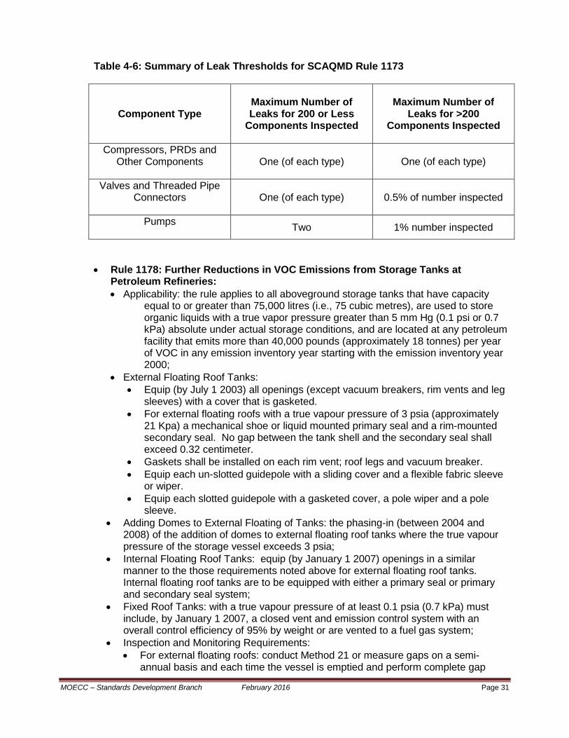
Table 4-6: Summary of Leak Thresholds for SCAQMD Rule 1173
Component Type
Maximum Number of Leaks for 200 or Less
Components Inspected
Maximum Number of Leaks for >200
Components Inspected
Compressors, PRDs and Other Components
One (of each type) One (of each type)
Valves and Threaded Pipe Connectors
One (of each type) 0.5% of number inspected
Pumps Two 1% number inspected
• Rule 1178: Further Reductions in VOC Emissions from Storage Tanks at Petroleum Refineries: • Applicability: the rule applies to all aboveground storage tanks that have capacity
equal to or greater than 75,000 litres (i.e., 75 cubic metres), are used to store organic liquids with a true vapor pressure greater than 5 mm Hg (0.1 psi or 0.7 kPa) absolute under actual storage conditions, and are located at any petroleum facility that emits more than 40,000 pounds (approximately 18 tonnes) per year of VOC in any emission inventory year starting with the emission inventory year 2000;
• External Floating Roof Tanks: • Equip (by July 1 2003) all openings (except vacuum breakers, rim vents and leg
sleeves) with a cover that is gasketed. • For external floating roofs with a true vapour pressure of 3 psia (approximately
21 Kpa) a mechanical shoe or liquid mounted primary seal and a rim-mounted secondary seal. No gap between the tank shell and the secondary seal shall exceed 0.32 centimeter.
• Gaskets shall be installed on each rim vent; roof legs and vacuum breaker. • Equip each un-slotted guidepole with a sliding cover and a flexible fabric sleeve
or wiper. • Equip each slotted guidepole with a gasketed cover, a pole wiper and a pole
sleeve. • Adding Domes to External Floating of Tanks: the phasing-in (between 2004 and
2008) of the addition of domes to external floating roof tanks where the true vapour pressure of the storage vessel exceeds 3 psia;
• Internal Floating Roof Tanks: equip (by January 1 2007) openings in a similar manner to the those requirements noted above for external floating roof tanks. Internal floating roof tanks are to be equipped with either a primary seal or primary and secondary seal system;
• Fixed Roof Tanks: with a true vapour pressure of at least 0.1 psia (0.7 kPa) must include, by January 1 2007, a closed vent and emission control system with an overall control efficiency of 95% by weight or are vented to a fuel gas system;
• Inspection and Monitoring Requirements: • For external floating roofs: conduct Method 21 or measure gaps on a semi-
annual basis and each time the vessel is emptied and perform complete gap
MOECC – Standards Development Branch February 2016 Page 31

measurements of the rim seal system on a semi-annual basis or each time the vessel is emptied.
• For domed external roof tanks and internal floating roof tanks: visually inspect the rim seal system and employ a explosimeter to measure the lower explosive limit on a semi-annual basis and perform complete gap measurements of the rim seal system and all openings each time the tank is emptied but no less than once every ten years.
• For fixed roof tanks: tests to confirm compliance with the 95% control effectiveness requirement within 180 days of start-up and annually thereafter; andwhenever a modification to the system is made.
• Rule 1401: New Source Review of Toxic Air Contaminants:
• Applicability: to applications, received by the SCAQMD after June 1 1990, for
new or modified facilities; • Maximum Incremental Cancer Risk (MICR) Requirements: the new or modified
process unit will not result in any of the following: • an increased MICR greater than one-in-one million at any receptor location if
the permit unit is constructed without best available control for toxics (T-BACT);
• an increased MICR greater than ten in one million at any receptor location, if the permit unit is constructed with T-BACT; nor
• a cancer burden (i.e., the estimated increase in the occurrence of cancer cases in a population subject to a MICR of greater than or equal to one-in-one million resulting from exposure to toxic air contaminants) of greater than 0.5.
• Cumulative increase in Chronic Hazard Index and Acute Hazard Index: shall not exceed 1.0 (for both indices, respectively)
• Rule 1402: Control of Toxic Air Contaminants from Existing Sources:
• Applicability: to any existing facility that is subject to the California “Hot Spots”
Program (described above) for which the impact of total facility emissions exceeds the following action risk levels: • 25-in-one million maximum incremental cancer risk (MICR) at any receptor
location; • A total acute or chronic hazard index of 3.0 for any target organ system at
any receptor location; and • A cancer burden (i.e., the estimated increase in the occurrence of cancer
cases in a population subject to a MICR of greater than or equal to one-in-one million resulting from exposure to toxic air contaminants;
• Risk assessment requirements: are required when, upon investigation by the SCAQMD executive officer, there is a potential for exceedance of the action risk levels;
• Risk reduction requirements: risk reduction measures are required when a required risk assessment confirms exceedance of the action risk levels. The implementation of risk reduction measures to reduce risks below the risk action levels must, generally, be completed within three years where a time extension of up to two years will be allowed if the risk assessment indicates less than the significant risk level (e.g., a MICR of less than one-in ten thousand; and an acute or chronic hazard index of less than 5.0).
MOECC – Standards Development Branch February 2016 Page 32

4.4.2 Louisiana
In general, as per US federal delegation of authority, Louisiana air pollution requirements for petroleum refineries are consistent with US federal air pollution requirements. For example, the US federal register of Tuesday February 24 2015 included a US federal delegation of authority to the state of Louisiana for New Source Performance Standards and National Emission Standards for Hazardous Air Pollutants. In addition, consistent with most of the other state environmental protection agencies, the US federal Title V (or Part 70) operating permit program is also implemented by the State of Louisiana. These operating permits combine all enforceable requirements, including emissions limits, monitoring, recordkeeping, and reporting provisions, into one document. Owners of sources with operating permits must certify that the source is in compliance each year, and the permits must be renewed every 5 years. Each proposed initial Part 70 permit, renewal, and significant modification is subject to a 30-day public comment period, with an opportunity for a hearing, and a 45-day US EPA review period. Following is a summary of the Louisiana air pollution requirements for storage vessels, equipment leaks and wastewater treatment and loading operations at petroleum refineries in Louisiana: Storage Vessels: requires compliance with 40CFR60 subpart Kb (for storage vessels of petroleum liquids that construction or reconstruction commenced after July 23 1984) and 40CFR61 Subpart Y (benzene storage). The Louisiana requirements are also anticipated to be consistent with 40CFR63, Subpart CC (aka, Refineries MACT 1) and 40CFR63 Subpart G (for storage vessels in the synthetic organic chemical manufacturing industry). Equipment Leaks: See Table 4-7 for a summary comparison between US federal rules and requirements in California, Louisiana and Texas, to address equipment leaks. Wastewater Treatment: requires compliance with 40CFR61 Subpart FF – National Emission Standard for Benzene Waste Operations and also includes the following specific requirements for oil/water separators: • A container having all openings sealed and totally enclosed liquid contents. All gauging
and sampling devices will be gas-tight except when gauging or sampling is taking place; • A container equipped with a floating roof, consisting of a pontoon type, double deck
type roof, or internal floating cover which rests or floats on the surface of the contents and is equipped with a closure seal or seals to close the space between the roof edge and container wall. All gauging and sampling devices will be gas-tight except when gauging or sampling is taking place;
• A container equipped with a vapor disposal system capable of processing such organic vapors and gases so as to limit their emission to the atmosphere to the same extent as 1 and 2, above, and with all container gauging and sampling devices gas-tight except when gauging or sampling is taking place;
• Other equivalent equipment or means as may be approved by the administrative authority.
MOECC – Standards Development Branch February 2016 Page 33

Loading Operations: • For non-marine loading to vessels with capacities in excess of 200 US gallons (~ 750
litres): • the loading of volatile organic compounds must include a vapour collection and a
vapour return line or a control system that reduces the emissions of volatile organic compounds by at least 90 per cent.
• For marine loading operations that would emit greater than 25 tons per year of volatile organic compounds (greater than 100 tons per year in some areas of Louisiana): must, • include a vapour collection and a control system that reduces the emissions of
volatile organic compounds by at least 90 per cent; and • comply with the following volatile organic compound emission limits: • barge loading of gasoline – 70 mg of total organic compounds per litre of VOC
loaded; • barge loading of crude oilor other VOCs – 30 mg of total organic compounds per
litre of VOC loaded; • ship loading of gasoline – 30 mg/litre of of VOC loaded; and • ship loading of crude oil or other VOCs – 12 mg/litre of VOCs loaded.
4.4.3 Texas Similar to the state of Louisiana, air pollution requirements for Texas are consistent with US federal air pollution requirements. Similar to most states, Texas has generally implemented the federal (Title V) operating permit program. Following is a summary of the Texas air pollution requirements for storage vessels, equipment leaks, wastewater treatment systems and loading operations at petroleum refineries: Storage Vessels: petroleum refineries in Texas are anticipated to require compliance with 40CFR60 subpart Kb (for storage vessels of petroleum liquids that construction or reconstruction commenced after July 23 1984); 40CFR61 Subpart Y (Benzene Storage); and 40CFR63, Subpart CC (aka, Refineries MACT 1) and 40CFR63 Subpart G (for storage vessels in the synthetic organic chemical manufacturing industry). Specifically, Division 1 (Storage of Volatile Organic Compounds); Subchapter B (General Volatile Organic Compound Sources) of Chapter 115 (Control of Air Pollution from Volatile Organic Compounds) of the Texas Administrative Code (TAC) includes the following inspection and repair requirements for storage vessels that contain volatile organic compounds : • Storage vessels equipped with an internal floating roof shall be visually inspected,
through a roof hatch, every 12 months. If the inspection indicates that the floating roof is not resting on the surface of the liquid (and is not resting on the leg supports); or liquid has accumulated on the roof; or the seal is detached or there are holes or tears in the seal fabric; or there are visible gaps between the seal and the storage vessel wall then the identified defects shall be repaired or the tank emptied and degassed within up to 120 days.
• Storage vessels equipped with external floating roofs shall have any seal gaps between the secondary seal and the vessel wall, every 12 months. Any accumulation of gaps (that are greater than 1/8 inch in width) that is greater than 1 square inch per foot of tank diameter must be repaired or the storage vessel must be emptied and degassed within up to 120 days.
MOECC – Standards Development Branch February 2016 Page 34

Subchapter F (Miscellaneous Industrial Sources) of Chapter 115 of the TAC requires that vapours emitted during storage vessel emptying and degassing shall be directed to an air pollution control device that maintains a control efficiency of at least 90%. Equipment Leaks: See Table 4-7 for a summary comparison between US federal rules and requirements in California, Louisiana and Texas, to address equipment leaks. Wastewater Treatment: It is anticipated that 40CFR61 (National Emission Standard for Benzene Waste Operations) is applied to benzene waste management including wastewater treatment systems at Texas petroleum refineries. Loading Operations: Division 1 (Loading and Unloading of Volatile Organic Compounds) of Subchapter Chapter 115 of the TAC requires the use of vapour collection and control in conjunction with: • 90% control and leak-free operation for the truck and railcar loading of gasoline; and • no greater than 10.8 mg of VOC emitted to atmosphere for marine loading operations. Compliance with US federal requirements within 40CFR63 subpart R and 40CFR63 subpart Y for truck/railcar and marine loading of gasoline, respectively. Note: US federal consent decrees that have been issued to specific facilities as a result of the US National Petroleum Initiative, include more stringent requirements than US federal and state rules.
MOECC – Standards Development Branch February 2016 Page 35

Table 4-7: Summary of Leak Detection and Repair Requirements for Different Jurisdictions
Aspect for Comparison
Canada California Louisiana Texas US Federal
Canadian Council of Ministers of the
Environment (CCME):
Environmental Code of Practice
for the Measurement and Control of VOC Emissions from
Equipment Leaks
SCAQMD Rule 1173:
Control of
Volatile Organic Compound Leaks and
releases from components at
Petroleum Facilities and
Chemical Plants
Louisiana Administrative
Code (LAC) Title 33 Environmental Quality, Chapter 51 – Louisiana
Refinery MACT and Louisiana
Non-HON MACT
LAC Title 33 Environmental
Quality, Chapter 51 – Louisiana
Refinery MACT and Louisiana
Non-HON MACT
With Consent Decree
Enhancements
Texas Administrative
Code (TAC), Title 30 Environmental Quality, Chapter
115
40CFR63, Subpart H National Emission
Standards for Organic
Hazardous Air Pollutants for
Equipment Leaks
Listed Exemptions
Components in continuous vacuum service, heavy liquid service, and that are inaccessible. Valves less than 0.75 inches or 1.875 cm nominal size. Valves that are not externally regulated (i.e., check valves). Components that are of leakless design (i.e., sealless pumps, bellow seal valves, pumps with double mechanical seals and a barrier fluid at higher pressure than operating pump pressure).
The following exemptions to the rule shall supply, to the satisfaction of the Executive Officer, proof of the applicable criteria:
Components which present a safety hazard.
Components exclusively handling natural gas or fluids with a VOC content of ten percent or less.
Components operating under negative pressure.
Components that
Vacuum service Unsafe to monitor Dual Mechanical seals with barrier fluid and alarm Closed vent system No detectable emissions Difficult to monitor Equipment in service <300 hours per year
Components in-service: VOC’s having a true vapour pressure than 0.3 kPa at 20 oC.; less than 10% VOC by weight. Conservation vents on atmospheric storage tanks that are actuated by vacuum. All pumps and compressors that are equipped with a shaft sealing system. Reciprocating compressors and positive displacement pumps. Pressure relief valves, open-ended
Vacuum service Unsafe to monitor Dual Mechanical seals with barrier fluid and alarm Closed vent system No detectable emissions Difficult to monitor <.75" FECs in instrumentation systems PRVs equipped with rupture disk
MOECC – Standards Development Branch February 2016 Page 36
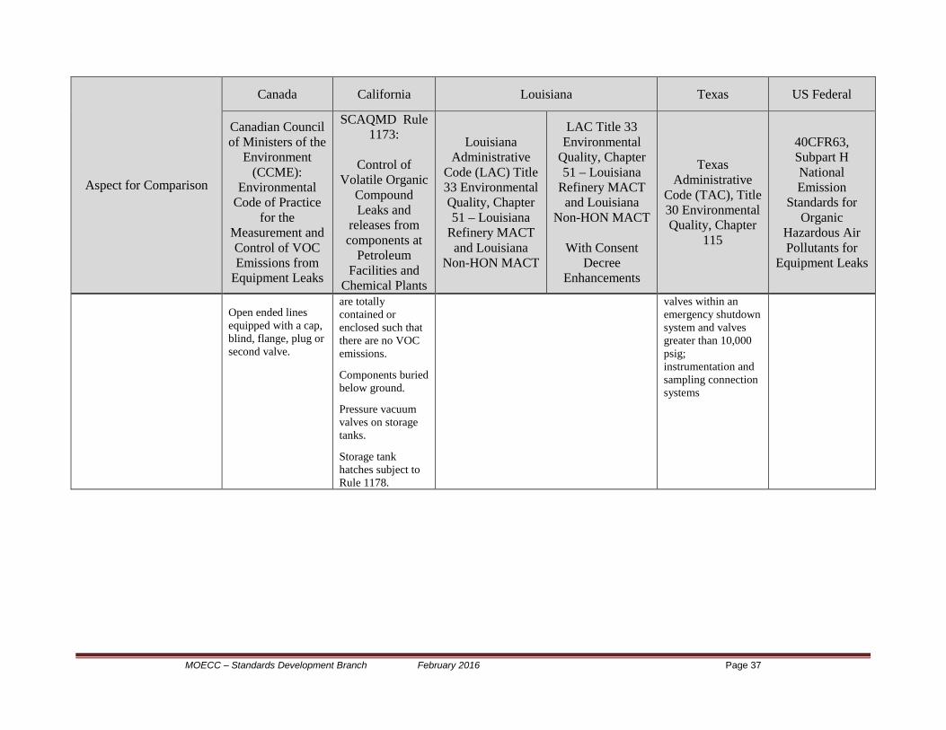
Aspect for Comparison
Canada California Louisiana Texas US Federal
Canadian Council of Ministers of the
Environment (CCME):
Environmental Code of Practice
for the Measurement and Control of VOC Emissions from
Equipment Leaks
SCAQMD Rule 1173:
Control of
Volatile Organic Compound Leaks and
releases from components at
Petroleum Facilities and
Chemical Plants
Louisiana Administrative
Code (LAC) Title 33 Environmental Quality, Chapter 51 – Louisiana
Refinery MACT and Louisiana
Non-HON MACT
LAC Title 33 Environmental
Quality, Chapter 51 – Louisiana
Refinery MACT and Louisiana
Non-HON MACT
With Consent Decree
Enhancements
Texas Administrative
Code (TAC), Title 30 Environmental Quality, Chapter
115
40CFR63, Subpart H National Emission
Standards for Organic
Hazardous Air Pollutants for
Equipment Leaks
Open ended lines equipped with a cap, blind, flange, plug or second valve.
are totally contained or enclosed such that there are no VOC emissions.
Components buried below ground.
Pressure vacuum valves on storage tanks.
Storage tank hatches subject to Rule 1178.
valves within an emergency shutdown system and valves greater than 10,000 psig; instrumentation and sampling connection systems
MOECC – Standards Development Branch February 2016 Page 37

4.5 Other Relevant Documents
4.5.1 Report - Technical Evaluation of Options for Air Pollution Control of VOCs, NOx, SO2, and PM from the Petroleum Refining Sub-Sector, March 2014…
The above-noted report was commissioned by the Ministry of the Environment and Climate Change (MOECC) in support of joint efforts by the MOECC, Environment Canada and industry representatives to explore air pollution control options for the above-noted criteria air contaminants. The scope of the study encompassed the evaluation of a series of emission reduction technologies and strategies that are technically feasible at Ontario petroleum refineries. The evaluation took place between April 2011 and March 2014. Although the study and report focused on criteria air contaminants (rather than air toxins such as benzene and benzo[a]pyrene) the air pollution control options related to volatile organic compounds may be relevant to controlling benzene air emissions from petroleum refineries and petrochemical facilities. Following is an excerpt from Chapter 4, Add-On Control and Pollution Prevention Technology Profiles, of this report.
a) Equipment Leaks
Leaking equipment is one of the largest sources of VOC emissions at petroleum refineries. A typical refinery has tens of thousands of components that can leak, including valves, connectors, pumps, sampling connections, compressors, pressure-relief devices, and open-ended lines. Emissions typically occur from seal or gasket failure due to normal wear or improper maintenance. Leak Detection and Repair (LDAR) is a work practice designed to identify leaking equipment so that emissions can be reduced through repairs. A component that is subject to LDAR requirements must be monitored at specified, regular intervals to determine whether or not it is leaking. Any leaking component must then be repaired or replaced within a specified time frame. LDAR programs have evolved over time to meet various levels of stringency and to improve program effectiveness by employing the best practices identified at facilities with successful LDAR programs. We identified six options for reducing VOC emissions from equipment leaks.
• Basic LDAR (option #26). This option is similar to the fugitive VOC emission controls identified in the CCME Code of Practice6.
• Advanced LDAR (option #27). This option would simply lower the leak threshold and increase the monitoring frequency. In theory, VOC emissions would be reduced since smaller leaks would be detected and repaired more frequently. However, the USEPA has found that the VOC reductions anticipated from lower leak thresholds and increased monitoring have not been achieved in practices due to improper monitoring7. EPA determined that failure to accurately detect leaks may be due to a lack of internal quality control oversight or management accountability for the LDAR programs. In other words,
6 Canadian Council of Ministers of the Environment (CCME), Environmental Code of Practice for the Measurement and Control of Fugitive VOC Emissions from Equipment Leaks, October 1993, website, http://www.ccme.ca/assets/pdf/pn_1106_e.pdf, retrieved 3 August 2011. 7 Enforcement Alert: Proper Monitoring Essential to Reducing ‘Fugitive Emissions’ Under Leak Detection and Repair Programs; USEPA Office of Compliance and Enforcement; EPA 300-N-99-014; October 1999.
February 16, 2016 DRAFT for discussion purposes Page 38

simply lowering the leak definition and increasing the monitoring frequency did not consistently achieve the anticipated emission reductions.
• Enhanced LDAR (technology option #28). This option includes a set of best practices that can remedy many of the problems that occur from improper management of an LDAR program. Enhanced LDAR is based on the best management practices found at refineries in the U.S8 and requirements found in recent USEPA consent decrees. These practices include written operating procedures, periodic training, 3rd party audits, equipment changes such as low-leak valves and packing, and QA/QC of LDAR data. Additionally, enhanced LDAR includes lower leak thresholds and increased monitoring frequency from the levels in the CCME Environmental Code of Practice.
• SMART LDAR (option #29). This option utilizes infrared (IR) cameras rather than the Method 21 analyzers traditionally used for detecting leaks. Our understanding is that the IR camera technology has not yet been used as a stand-alone technique for detecting leaks at any plant site to fulfill US regulatory requirements. In addition, USEPA has been “unable to estimate the VOC emissions achieved by an optical imaging program alone”9.
• HRVOC LDAR (option #30). This option has been employed in the U.S. and targets process streams containing highly-reactive VOC (HRVOC) such as ethylene and propylene. Very stringent leak definitions (100 ppm) are used for any stream containing an HRVOC, and the required time for the first attempt to repair leaks is reduced from 15 days to one or two days.
• Leak-less Equipment (option #31). This option would require modification or replacement of individual, chronic leaking equipment with low-leaking valve technologies. The CCME Code of Practice suggests that the installation of leak-tight equipment is the preferred option for fugitive emissions control.
It is recommended that the following five options be excluded from further consideration due to following reasons:
• First, we make the assumption that Ontario refineries are already employing the CCME Code of Practice for managing emissions from equipment leaks. Since the facilities are already implementing basic LDAR programs that appear to be in accordance with the CCME Code of Practice, option (#26) is not recommended for further analysis since it would not result in any additional emission reductions from the baseline.
• The advanced LDAR option (#27) is not recommended for further analysis because it does not include the best practices of the enhanced LDAR program which improve the reliability of monitoring data and the effectiveness of the LDAR program. Alone, this technology doesn’t produce consistently improved results.
• The stand-alone SMART LDAR option (#29) is not recommended for further analysis because these instruments do not yet provide a direct measure of leak concentrations from which emissions can be quantified. However, SMART LDAR may be included as a best management practice under the enhanced LDAR option.
• The HRVOC LDAR option (#30) is not recommended for further analysis because it would only apply to one of the facilities and thus is not generally applicable.
8 USEPA, Leak Detection and Repair – a Best Practices Guide, October 2007, website: http://www.epa.gov/oecaerth/resources/publications/assistance/ldarguide.pdf Technical Evaluation of Options for Control of VOCs, NOX, SO2 and PM from the Petroleum Refining Sub-Sector. 9 Federal Register /Vol. 76, No. 163 /Tuesday, August 23, 2011 / Oil and Natural Gas Sector: New Source Performance Standards and National Emission Standards for Hazardous Air Pollutants Reviews Technical Evaluation of Options for Control of VOCs, NOX, SO2 and PM from the Petroleum Refining Sub-Sector
MOECC – Standards Development Branch February 2016 Page 39

• The leakless equipment (#31) is not recommended for further analysis as a stand-alone option since it is included as one of the elements of the enhanced LDAR best management practices.
As a result, we propose to consider a single “Enhanced LDAR” option (technology option #28) that includes elements from the best management practices found in the U.S. that call for LDAR program design with various levels of more stringent requirements for leak definitions, monitoring frequency, and timeframes for repairing leaking components. Other best management practices in this option will include written procedures, periodic training, 3rd party audits, use of optical gas imaging technology, and use of “leakless” equipment.
(b) Wastewater Treatment Large volumes of wastewater containing VOCs are produced at petroleum refineries. Most wastewater from process areas enters the collection system through drains which are connected to the sewer system. There can be significant evaporation from the system if the drain is not sealed and vapours are allowed to escape. A water seal, often called a p-trap, can be used to effectively eliminate these emissions. This reduces the vaporization of hydrocarbon in the wastewater as it enters the drain and also prevents hydrocarbon vapours already in the sewer system from escaping. VOC emissions occur from evaporation treatment systems and ponds that are exposed to the air. Suppression technologies (e.g., seals, covers) reduce volatilization of VOCs and prevent their release to the ambient air. This allows the treatment process(es) following the collection system to achieve greater removal and/or destruction of VOCs. There is no CCME Guideline for VOC emissions from wastewater collection and treatment systems. The basic control options are similar for both parts of the wastewater system (collection system and treatment system). We identified five options for reducing VOC emissions from wastewater collection and treatment systems. Four options are recommended for further consideration and one option is not recommended, for the following reasons:
• Enclosing drain and collector systems (option #32). This option calls for installation of new equipment to prevent, reduce or control evaporation of liquid hydrocarbons from exposed surfaces within the wastewater collection system. The equipment includes water seals on drains and junction box vents and sealing manhole covers. The overall control efficiency of this method is estimated at an average of 65%. This option is recommended for further consideration since many U.S. refinery drain and collection systems have been successfully retrofitted with seals to reduce VOC emissions.
• System components enclosed with closed vent system and a control device (option #33). Collecting and venting the emissions from the collection system to a control device can achieve a control efficiency of greater than 95%. Granular activated carbon (GAC) is routinely used to control VOCs and benzene from wastewater collection components at refineries and petrochemical plants. This option is recommended for further consideration since many U.S. refinery drain and collection systems have been successfully vented to VOC control devices such as carbon absorption systems or incinerators.
• Oil/water separator with fixed roof vented to a control device (options #34). Covering these units with a fixed roof can allow any volatilized vapours to be collected and prevented from being released to the atmosphere. Actual emission reduction is only achieved if the hydrocarbon is destroyed or recovered. Thermal incinerators and carbon adsorption units are commonly used to destroy or recover the VOC, respectively. In general, fixed covers are more commonly used on new API separators. This option is recommended for further consideration because the use of fixed roofs vented to a control device has been used often and successfully to control emissions from oil/water separators in the U.S.
MOECC – Standards Development Branch February 2016 Page 40

• Oil/Water separator covered with a floating roof (option #35). By covering the surface of the wastewater with a floating roof, VOC evaporation into the air is reduced. Floating covers are generally used when existing separators must be covered for VOC control. This option is recommended for further consideration because the use of floating roofs has been used often and successfully to control emissions from oil/water separators in the U.S.
MOECC – Standards Development Branch February 2016 Page 41

• Waste Minimization (option #36). This option is designed to reduce the source of the VOC emissions (pollution prevention) through changes to the operation or design of the refinery, as opposed to controlling the emissions themselves with equipment. This strategy requires changes in the way process units feed the wastewater collection system, or how the system itself is operated or designed, and would vary from refinery to refinery10. For example, optimizing the performance of sour water strippers can lower the load of VOC entering the wastewater collection and treatment system. Note, because these operating and design practices might result in a major revamping of the refinery and there is significant variability between refineries, this option is not recommended for further consideration.
(c) Product Loading
The CCME11 Environmental Code of Practice for Vapour Recovery in Gasoline Distribution Networks deals with gasoline bulk terminals. The requirements include the use of submerged fill or bottom loading techniques, vapour recovery or vapour destruction, and leak-tight cargo vessels. For bulk gasoline terminals, the performance criteria are 35 mg/litre (0.29 lbs/1000 gals) and 97% VOC control. The Code of Practice appears to apply only to gasoline loading – other petroleum products are not covered. Also, requirements for vapour control or recovery for ship/barge and railcar loading have “been deferred to the next issue of the Code.” How material is loaded into the receiving container makes a significant difference in VOC vapour generation. Alternative loading techniques have been used to reduce turbulence that tends to increase vapour concentrations vented to the air. Alternative loading techniques included bottom loading or the use of submerged fill pipes (option #37). In bottom loading, the pipe enters from below the floor of the compartment and is always maintained below the liquid surface to minimize splashing. In submerged loading, the pipe through which new liquid is loading is placed very near the bottom of the container. This minimizes splashing as the liquid entry point will quickly become submerged in the compartment. This option is a proven commercialized technology that is already widely used and is recommended but does not require further analysis. VOC vapor recovery or destruction technologies are well understood and widely implemented to capture VOC vapour generated during the loading process and route those vapors to the control device. Capture and control systems can be designed to achieve various levels of stringency to control emissions from tank truck, ship/barge, and railcar loading. According to a leading control equipment vendor12, the majority of US refineries use vapor combustion units (VCU) (option #38) or carbon based vapor recovery units (VRU) (option #39) to control emissions. In the truck and marine loading applications about 70% use carbon adsorption units and 30% vapor combustion units. All other technologies (refrigeration, open top flare, etc.) make up less than 1%. Thus, it is recommended that the two most commonly used technologies – VCUs and VRUs, making up technology option #38 and #39, - be retained for further consideration.
10 IPIECA. Petroleum Refining Water/Wastewater Use and Management: Operations Best Practice Series. October 2010. See: http://www.ipieca.org/publication/petroleum-refining-water-wastewater-use-and-management. 11 Canadian Council of Ministers of the Environment (CCME), Environmental Code of Practice for Vapour Recovery in Gasoline Distribution Networks, March 1991, website, www.ccme.ca/assets/pdf/pn_1057_e.pdf, retrieved 3 August 2011. 12 Canadian Council of Ministers of the Environment (CCME), Environmental Code of Practice for Vapour. MOECC – Standards Development Branch February 2016 Page 42

(d) Storage The basic designs of storage tanks at petroleum refineries include fixed-roof tanks, external floating roof tanks, internal floating roof tanks, and domed external floating roof tanks. VOC emissions and potential control options depend on the specific design and construction of the tank and the characteristics of the petroleum liquids stored. The CCME13 Environmental Guidelines for Controlling Emissions of Volatile Organic Compounds from Above Ground Storage Tanks identified requirements and specifications for reducing emissions from storage tanks. In 1998, CPPI14 issued a guideline with respect to the measurement and reduction of VOCs from above ground storage tanks. This guideline recommended that CPPI refineries adopt the provisions of the June 1995 CCME Guidelines. Our review of each facility’s ESDM report indicated that most facilities appear to be implementing the CCME Guidelines. The following two control options are both proven commercialized technologies identified that are widely used and are recommended but do not require further analysis:
• Fixed Roof Tank Pressure Vacuum Valves (option #40). The CCME Guidelines requires pressure/vacuum relief valves (also known as breather valves, conservation vents, or safety vents) on smaller fixed roof tanks (< 75 m3 capacity) to minimize evaporation loss. The pressure/vacuum valve allows the tanks to operate at a slight internal pressure or vacuum to prevent the release of vapours during very small changes in temperature, pressure, or liquid level.
• Fixed Roof Tank Retrofits (option #41). The CCME Guidelines require large fixed roof tanks (>75 m3 capacity) to be equipped with either a vapour balancing system, retrofitted with an internal floating roof, or vented to a vapour recovery or destruction control system. The specific type of control required depends on the specific size of the tank and the vapour pressure of the product stored.
Two options were identified which go beyond the requirements of the CCME Guidelines. These options consist of the following enhanced equipment specifications:
• Retrofitting floating roof tank deck fittings to reduce emissions from deck fittings (option #42). Evaporative losses occur through roof penetrations, including those for deck fittings such as slotted guide-poles, access hatches (manways), and adjustable roof legs. Retrofit kits are readily available that use gaskets, wipers, pole sleeves, covers, etc. to minimize evaporation from deck fittings such as slotted guide-poles. This option is recommended for further evaluation since several U.S. jurisdictions are requiring these retrofits to further reduce VOC emissions.
• Retrofitting external floating roof tanks with domes (option #43). Wind blowing across external floating roof tanks causes evaporative losses. Retrofitting external floating roof tanks with a dome to block the wind from causing evaporative losses and to shield the roof from the deteriorating effects of weather. This option is recommended for further evaluation since several U.S. jurisdictions are requiring these retrofits to further reduce VOC emissions.
13 Canadian Council of Ministers of the Environment (CCME), Environmental Guidelines for Controlling Emissions of Volatile Organic Compounds from Above Ground Storage Tanks, June 1995, http://www.ccme.ca/assets/pdf/pn_1180_e.pdf
14 CPPI was renamed in October 2012 to Canadian Fuels Association
MOECC – Standards Development Branch February 2016 Page 43

Two other options that go beyond the CCME Guidelines were not recommended for further evaluation. These options are:
• Add-on control of roof landing losses (option #44). As a tank is emptied, the liquid level in the tank may be lowered to below the level of the floating roof support legs. The roof will rest (land) on the supporting legs rather than on the liquid, creating a vapor space which enables vapors from the VOC remaining in the tank to accumulate and release to the atmosphere during refilling. Standard operation of floating roof tanks assumes that there is continuous contact of the floating roof with the liquid below the floating roof. However, studies in Texas15 have shown that roof landings frequently occurred at several for-hire bulk terminals. Roof landings are much less common at refineries16. Control options include requiring use of lowest lander height setting for in-service roof landings (to minimize the vapor space), installation of vapor recovery/control for use when roof is landed or modifying the tank to reduce the landed height. It is recommended to follow operating procedures that do not allow roofs to be landed, except in the circumstance of emptying/degassing for repair. Therefore, no further analysis is necessary.
• Add-on control for degassing and interior tank cleaning (option #45). Before a tank is cleaned, it must be degassed (which is the removal of vapors) so personnel can safely enter to clean the tank and remove accumulated sludge. The sludge removed from the tank can contain residual VOC liquid that may evaporate when exposed to the atmosphere. Several purges are normally required to ensure that all hydrocarbon vapours are removed from the tank prior to entry. Controlling tank degassing/cleaning emissions in the U.S. is typically done by routing vapors to a mobile control device (such as a thermal incinerator or carbon adsorption unit) that is owned and operated by an outside contractor. Emissions from degassing of storage tanks are believed to be small (e.g., less than 1% of VOC emissions for a typical refinery) based on data for similar refineries located in New Jersey38; therefore, this option is excluded based on fact that only de minimis levels of emissions would be controlled using this technology.
15 Texas Commission on Environmental Quality, Houston SIP Modeling Update: Roof Landing Loss Emissions, www.tceq.state.tx.us/assets/public/implementation/air/am/committees/pmt_set/20080423/20080423--nesvacilhgb_ sip_updatel.pdf , retrieved on August 29, 2012. 16 Email communications from Danielle Nesvacil, TCEQ Emissions Assessment Section, to Ed Sabo, SRA International, dated August 29, 2012. Most landings occurred at tank-for-hire/tank leasing facilities; gasoline pipeline breakout stations and refineries only landed roofs for the seasonal RVP change, if at all. Most of the tankfor- hire roof landings appeared to be “convenience landings,” i.e., not performed for maintenance or emergency purposes, but to maximize liquid withdrawal from the storage tanks.
MOECC – Standards Development Branch February 2016 Page 44

Table 4-4: Summary of Pollution Control and Pollution Prevention Technology Options (for Volatile Organic Compounds) Selected for Further Analysis (Excerpt from Chapter 4 of the above-noted document)
Equipment Pollution Control/Prevention Technology Options Selected for Further Analysis
Equipment Leaks Enhanced LDAR
Wastewater Collection &
Treatment
Enclosing drain and collector systems
System components enclosed with closed vent system and a control device.
Oil/water separator with a floating roof.
Oil/water separator with a fixed roof to a control device.
Loading Operations Vapour recovery systems.
Vapour combustion system.
Storage Tanks Enhanced equipment specifications for floating roof deck fittings.
Retrofitting external floating roof tanks with domes.
MOECC – Standards Development Branch February 2016 Page 45

4.6 Sarnia Monitoring Workshop (November 5-6, 2014) The Air & Waste Management Association – Ontario Section in partnership with representatives of the Ontario Ministry of the Environment & Climate Change and other sponsors such as the Canadian Fuel Association, Sarnia Lambton Environmental Association and equipment vendors and consultants organized a monitoring workshop that was focused on the latest monitoring technology and rules for fugitive volatile organic compound air emissions from petroleum refineries and petrochemical facilities. The purpose of this work-shop was to review the latest monitoring technology within Canada and the United States; to review lessons-learned from both the regulator and regulated perspectives; and to provide an opportunity for a community viewpoint to be presented. The results are intended to support development of proposed technical standards for petroleum refineries and petrochemical facilities.
The possibility of a multi-organization collaboration, to test and assess emerging fugitive emission monitoring technologies at two to three industry sites in Ontario, was a key outcome of this workshop. The objective of the multi-organization collaboration would be to identify new technologies and approaches to monitoring and minimizing fugitive volatile organic compound (VOC) emissions (with a focus on hazardous air pollutants such as benzene) from petroleum refineries and petrochemical facilities.
MOECC – Standards Development Branch February 2016 Page 46

Rationale Document: Proposal for a Petrochemical Industry Standard
Table 4-1: Summary of U.S. Federal Requirements for Storage Vessels for Petrochemical Facilities and Petroleum Refineries
National Emission Standards for Hazardous Air Pollutants from
Petroleum Refineries (aka, Refineries MACT 1)
National Emission Standards for Organic Hazardous Air Pollutants from
the Synthetic Organic Chemical Manufacturing Industry for Process
Vents, Storage Vessels, Transfer Operations, and Wastewater
(aka, part of the "HON" NESHAP)
National Emission Standards for Hazardous Air Pollutants:
Miscellaneous Organic Chemical Manufacturing
(aka, "MON" NESHAP).
National Emission Standards for Storage Vessels (Tanks) - Control Level 2
(aka, Generic MACT for storage vessels).May-June 2014 Proposal
Subpart K: Between Jun 11/73 and May 19/78
Subpart Ka: Between May 18/78 and Jul 23/84
Subpart Kb: After
July 23/84Subpart CC Subpart G Subpart FFFF Subpart WW -
1. Floating Roof Requirements:
Applicability:
Design Specifications?(e.g., cover-type; sealing system; opening
requirements)No Yes Yes; enhanced from subpart Ka Yes
Yes; including requirements for improved deck fittings and controls for guidpoles; and enhanced inspection, record-keeping and reporting requirements relative to the requirements in the Refinery Mact 1 and HON NESHAP.
Operational Requirements? No Yes Yes Yes
Inspection and/or Monitoring Requirements? No Yes Yes Yes
Record-Keeping Requirements? Yes Yes Yes Yes
Reporting Requirements? No No No Yes
Allowance for alternative means? No No No Yes Yes
Repair Requirements? No No Yes (related to seals) Yes Yes
2. Vapour Recovery System Requirements:
Applicability:
Performance Requirements: None specified
Requires 95% reduction, by weight, of volatile organic compound vapours; with an allowance for an alternative means of emission limitation
Requires 95% reduction, by weight, of volatile organic compound vapours; with an allowance for an alternative means of emission limitation.
Requires 95% reduction, by weight, of volatile organic compound vapours; with an allowance for an alternative means of emission limitation. Also requires only 90% reduction for control devices installed on or before December 31, 1992.
Requires 95% reduction, by weight, of volatile organic compound vapours or to an exit concentration of organic compounds (or HAP) of ≤ 20 ppmv; with an allowance for an alternative means of emission limitation.
Capacities > 151 m3(except for storage vessels that are used for "custody transfer"); with true vapour pressure (VP; as stored) between 10.3 and 76.6 kPa.
VP means the vapour pressure of the petroleum liquid (as stored).
Capacities > 151 m3(except for storage vessels, with capacities less than 1590 m3, that are used for "custody transfer"); with true VP (as stored) between 10.3 and 76.6 kPa.
VP means the vapour pressure of the petroleum liquid (as stored).
New Source Performance Standards (40CFR60)
Standards of Performance for Storage Vessels for Petroleum Liquids for Which Construction, Reconstruction or Modification Commenced…
US Federal Storage Vessel Requirements
National Emission Standards for Hazardous Air Pollutants (40CFR63)
Capacities > 75 m3(except for storage vessels, with capacities less than 1590 m3, that are used for "custody transfer"; plus other exemptions listed in section 60.110b of subpart Kb); with true VP (as stored) between 5.2 and 76.6 kPa for vessels with capacities greater than 151 m3; or between 27.6 and 76.6 kPa for vessels with capacities between 75 and 151 m3.
VP means the vapour pressure of the petroleum liquid (as stored).
Group 1 - Existing Sources: Capacities ≥ 177 m3 (and maximum VP ≥ 10.4 kPa; and annual average VP ≥ 8.3 kPa; and annual average concentration of HAP > 4% by weight)
Group 1 - New Sources:i) Capacities ≥ 151 m3 (and maximum VP ≥ 3.4 kPa; and annual average concentration of HAP > 2% by weight); orii) Capacities between 76 and 151 m3 (and maximum VP ≥ 77 kPa; and annual average concentration of HAP > 2% by weight).
VP means true vapour pressure of stored l iquid at storage temperature.
Group 1 - Existing Sources: i) Capacities ≥ 151 m3 (and maximum VP ≥ 5.2 kPa); orii) Capacities between 75 and 151 m3 (and maximum VP ≥ 13.1 kPa)
Group 1 - New Sources:i) Capacities ≥ 151 m3 (and maximum VP ≥ 0.7 kPa); orii) Capacities between 38 and 151 m3 (and maximum VP ≥ 13.1 kPa).
VP means true vapour of total organic hazardous air pollutants (HAPs).
Group 1 - Existing Sources: i) Capacities ≥ 37.9 m3 (or 10,000 US gallons) (and maximum VP ≥ 6.9 kPa).
Group 1 - New Sources:i) Capacities ≥ 37.9 m3 (and maximum VP ≥ 0.69 kPa); or
VP means true vapour of total organic hazardous air pollutants (HAPs).
Section 63.1060 (of subpart WW): "The provisions of this subpart apply to the control of air emissions from storage vessels for which another subpart references the use of this subpart for such air emission control. These air emission standards for storage vessels are placed here for administrative convenience and only apply to those owners and operators of facilities subject to a referencing subpart. The provisions of subpart A (General Provisions) of this part do not apply to this subpart except as noted in the referencing subpart."
For storage vessels with capacities greater than 151 m3; and true vapour pressures greater than 76.6 kPa.
For storage vessels with capacities greater than 151 m3; and true vapour pressures greater than 76.6 kPa.
For storage vessels with capacities greater than 151 m3; and true vapour pressures greater than 76.6 kPa.
Group 1 storage vessels with a maximum true VP ≥ 76.6 kPa.
Group 1 storage vessels with a maximum true VP ≥ 76.6 kPa.
See 40CFR63 subpart G,sections 63.119 to 63.121
Yes, procedures to determine compliance
See 40CFR63 subpart WW
Specified in each separate referencing subpart.
Summary of Federal Register Proposal (Vol. 79, No. 125, June 30, 2014) related to storage vessels:
i) Change in the Refinery MACT 1 definition of Group 1 storage vessels to include smaller capacity storage vessels. In summary, the US EPA is proposing the adoption of the HON MACT (i.e., subpart G) definitions for Group 1 storage vessels.
ii) A shift from current Refinery MACT 1 requirements (i.e., subpart CC) to storage vessel Generic MACT (subpart WW) requirements. In summary, this would require the implementation of improved deck fittings and controls for guidepoles; and related enhanced inspection, record-keeping and reporting requirements.
MOECC – Standards Development Branch February 2016 Page 47

Rationale Document: Proposal for a Petrochemical Industry Standard
Table 4-2: Summary of U.S. Federal LDAR Requirements for Petrochemical Facilities and Petroleum Refineries
MOECC – Standards Development Branch February 2016 Page 48
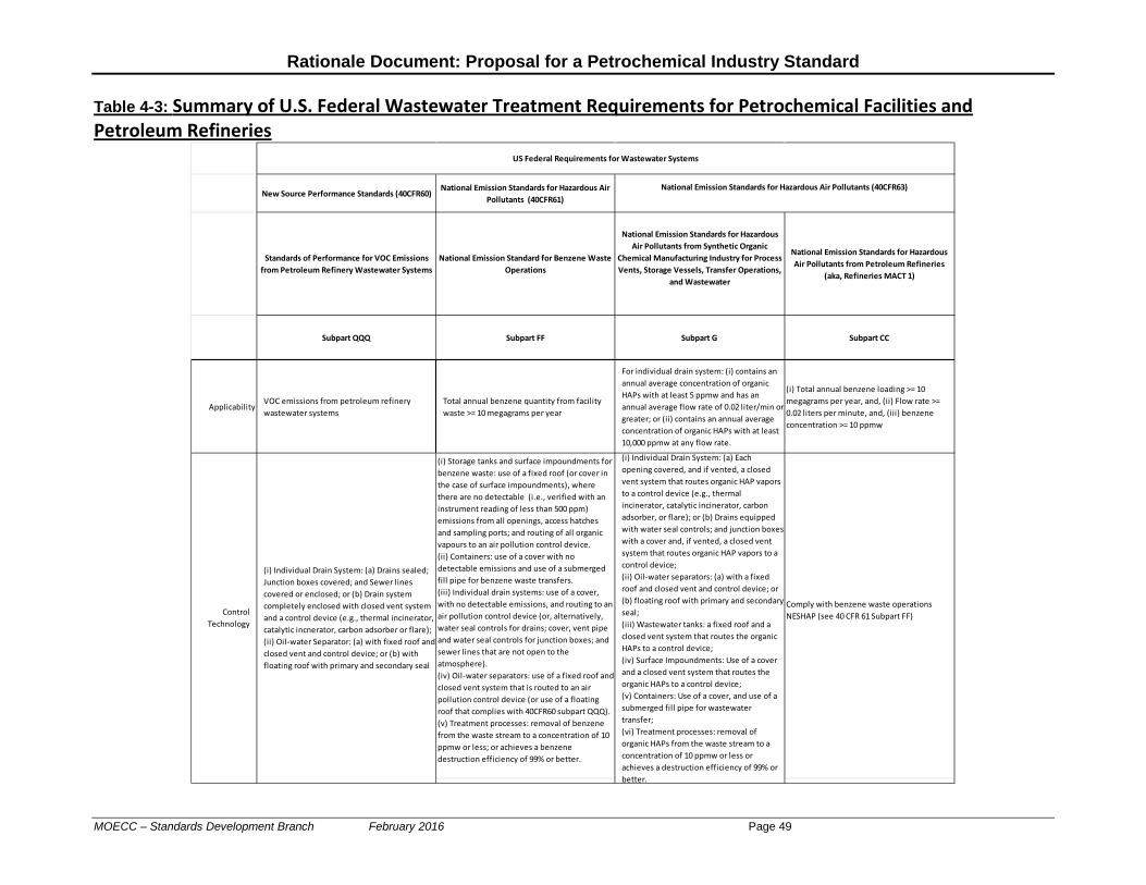
Rationale Document: Proposal for a Petrochemical Industry Standard
Table 4-3: Summary of U.S. Federal Wastewater Treatment Requirements for Petrochemical Facilities and Petroleum Refineries
New Source Performance Standards (40CFR60)National Emission Standards for Hazardous Air
Pollutants (40CFR61)
Standards of Performance for VOC Emissions from Petroleum Refinery Wastewater Systems
National Emission Standard for Benzene Waste Operations
National Emission Standards for Hazardous Air Pollutants from Synthetic Organic
Chemical Manufacturing Industry for Process Vents, Storage Vessels, Transfer Operations,
and Wastewater
National Emission Standards for Hazardous Air Pollutants from Petroleum Refineries
(aka, Refineries MACT 1)
Subpart QQQ Subpart FF Subpart G Subpart CC
ApplicabilityVOC emissions from petroleum refinery wastewater systems
Total annual benzene quantity from facility waste >= 10 megagrams per year
For individual drain system: (i) contains an annual average concentration of organic HAPs with at least 5 ppmw and has an annual average flow rate of 0.02 liter/min or greater; or (ii) contains an annual average concentration of organic HAPs with at least 10,000 ppmw at any flow rate.
(i) Total annual benzene loading >= 10 megagrams per year, and, (ii) Flow rate >= 0.02 liters per minute, and, (iii) benzene concentration >= 10 ppmw
(i) Storage tanks and surface impoundments for benzene waste: use of a fixed roof (or cover in the case of surface impoundments), where there are no detectable (i.e., verified with an instrument reading of less than 500 ppm) emissions from all openings, access hatches and sampling ports; and routing of all organic vapours to an air pollution control device.(ii) Containers: use of a cover with no detectable emissions and use of a submerged fill pipe for benzene waste transfers.(iii) Individual drain systems: use of a cover, with no detectable emissions, and routing to an air pollution control device (or, alternatively, water seal controls for drains; cover, vent pipe and water seal controls for junction boxes; and sewer lines that are not open to the atmosphere).(iv) Oil-water separators: use of a fixed roof and closed vent system that is routed to an air pollution control device (or use of a floating roof that complies with 40CFR60 subpart QQQ).(v) Treatment processes: removal of benzene from the waste stream to a concentration of 10 ppmw or less; or achieves a benzene destruction efficiency of 99% or better.
Comply with benzene waste operations NESHAP (see 40 CFR 61 Subpart FF)
(i) Individual Drain System: (a) Drains sealed; Junction boxes covered; and Sewer lines covered or enclosed; or (b) Drain system completely enclosed with closed vent system and a control device (e.g., thermal incinerator, catalytic incnerator, carbon adsorber or flare); (ii) Oil-water Separator: (a) with fixed roof and closed vent and control device; or (b) with floating roof with primary and secondary seal
Control Technology
(i) Individual Drain System: (a) Each opening covered, and if vented, a closed vent system that routes organic HAP vapors to a control device (e.g., thermal incinerator, catalytic incinerator, carbon adsorber, or flare); or (b) Drains equipped with water seal controls; and junction boxes with a cover and, if vented, a closed vent system that routes organic HAP vapors to a control device;(ii) Oil-water separators: (a) with a fixed roof and closed vent and control device; or (b) floating roof with primary and secondary seal;(iii) Wastewater tanks: a fixed roof and a closed vent system that routes the organic HAPs to a control device;(iv) Surface Impoundments: Use of a cover and a closed vent system that routes the organic HAPs to a control device;(v) Containers: Use of a cover, and use of a submerged fill pipe for wastewater transfer;(vi) Treatment processes: removal of organic HAPs from the waste stream to a concentration of 10 ppmw or less or achieves a destruction efficiency of 99% or better.
National Emission Standards for Hazardous Air Pollutants (40CFR63)
US Federal Requirements for Wastewater Systems
MOECC – Standards Development Branch February 2016 Page 49
Rationale Document: Proposal for a Petrochemical Industry Standard
5. Summary of Current Methods to Minimize Emissions of Benzene and 1,3 Butadiene from Dominant Sources
The dominant sources of benzene and 1,3 butadiene (see Chapter 3 of this document) were identified as: • Process fugitives (e.g., leaks from pump and compressor seals, valves, pressure relief devices
and connectors); • Storage tanks; • Wastewater treatment systems; • Major point sources (e.g., process vents and process flares); and • Product loading. Process Fugitives and Leak Detection and Repair (LDAR) Programs: There are no current regulatory requirements for LDAR program in Ontario. All of the Ontario petrochemical facilities conduct LDAR programs to identify and repair sources of fugitive air emissions on a voluntary basis. The LDAR programs at Ontario petrochemical facilities generally conform to or exceed the Canadian Council of Ministers of the Environment (CCME) document, “Environmental Code of Practice for the Measurement and Control of Fugitive VOC Emissions from Equipment Leaks, October 1993” including the following key aspects: • Process fugitives (e.g., leaks from pump and compressor seals, valves, pressure relief devices
and connectors): all the petrochemical facilities voluntarily employ LDAR program that meets or exceeds 1993 CCME guideline:
o Range of leak definition for facilities: 500 ppm to 10,000 ppm; o Range of monitoring frequency for facilities varies from quarterly to annually; o Correlation equations method is the common emission estimation method used; o Facilities use U.S. EPA Method 21 approach.
Storage Vessels The majority of the storage tanks that contain predominant fractions (>5% by weight) of benzene or 1,3 butadiene generally use floating roof technology (internal or external floating roofs) as a method of minimizing air emissions. These floating roofs generally have the primary and secondary seals. However, there are some storage tanks which still have vertical fixed roofs with no vapour recovery device. Product Loading “Submerged loading” is a common approach to minimizing emissions of volatile organic compounds, including benzene or 1,3 butadiene. Wastewater Treatment Systems Wastewater treatment systems at Ontario petrochemical facilities include sewer systems and vents, dissolved air flotation systems, oil/water separators, aeration basins/clarifiers and storage
MOECC – Standards Development Branch February 2016 Page 50

Rationale Document: Proposal for a Petrochemical Industry Standard
tanks. Generally, these wastewater treatment systems are open to atmosphere or vented directly to atmosphere.
MOECC – Standards Development Branch February 2016 Page 51

Rationale Document: Proposal for a Petrochemical Industry Standard
6. Analysis of Any Gaps Between Current Methods in Ontario
and Other Jurisdictions The gap analysis between current methods in Ontario and other key jurisdictions for the dominant sources are summarized below: Process Fugitives • Ontario Regulation 419/05:
o There are no current regulatory requirements for Leak Detection and Repair program (LDAR) programs.
o Ontario petrochemical facilities voluntarily implement a LDAR program that meets or exceeds the 1993 CCME guideline of 10,000 ppm leak definition.
o The leak definition for these facilities varies from 500 ppm to 10,000 ppm, and the monitoring frequency varies from quarterly to annually.
• Current U.S. Federal Requirements for LDAR program: o Mandatory requirements for LDAR programs; o Requirements are more stringent than the CCME guideline, e.g., leak definition of 1000-
2000 ppm for pumps, and 500 ppm for valves, compressors, pressure relief devices and connectors (see NESHAP Subpart H). The monitoring frequency generally varies from monthly to quarterly;
o Enhanced LDAR programs -- includes more stringent leak definition of 100 ppm for valves, and generally required equipment upgrades such as leakless valves and packing.
Storage Vessels • Ontario Regulation 419/05
o No current regulatory requirements to address air emissions from storage vessels; o The majority of storage vessels in these 4 petrochemical facilities have floating roof
technology (external or internal roof); o However, some of the storage vessels in these facilities still have vertical fixed roofs, with
no vapour control device; • U.S. Federal Requirements for Storage Vessels:
o U.S. New Source Performance Standards (NSPS) for storage vessels equipped with either (i) a fixed roof with an internal floating roof; or (ii) an external floating roof. If the true vapour pressure exceeds 76.6 kPa, then the storage vessels equipped with a vapour recovery system and a control device that reduces inlet concentration by at least 95%.
o U.S. National Emissions Standards for Hazardous for Air Pollutants (NESHAP): In addition to above NSPS requirements, also includes design requirements for deck fittings and guide poles, and enhanced inspection, record keeping and reporting requirements.
MOECC – Standards Development Branch February 2016 Page 52

Rationale Document: Proposal for a Petrochemical Industry Standard
7. Consideration of Stakeholder and Community Feedback 7.1 Background
In April of 2013, a technical working group comprised of Ministry staff and petrochemical industry representatives (e.g., from Imperial Oil, LANXESS, NOVA and Styrolution) first met to discuss the proposed Petrochemical – Industry Standard. These meetings occurred every three to four months throughout 2013, 2014 and 2015, followed by progress update teleconferences in late 2015 and 2016. In May of 2013, representatives of the Aamjiwnaang First Nation and Walpole Island First Nation were first introduced to the proposed Petrochemical – Industry Standard. An additional community member also joined the group in 2015. Representatives of the Aamjiwnaang First Nation and Walpole Island First Nation also identified the need for capacity funding due to a large number of other projects these First Nations communities were being asked to participate in; and due to the relatively complex nature of the proposed Petrochemical – Industry Standard development. Throughout 2014 and into 2015, Ministry staff worked to identify and implement capacity enhancement options. In the spring of 2015 Environmental Health Strategies and their sub-contractors were hired to provide expertise with respect to air pollution requirements for petroleum refineries (with similar rules as the petrochemical sector) in the United States and First Nations consultation. These jurisdictional experts have met with the Aamjiwnaang First Nation and Walpole Island First Nation at a series of meetings in June and November of 2015, and February 2016. More detail with respect to meetings, industry stakeholders and First Nations partners can be found in Appendix B of this document.
7.2 Summary of Proposals and How Stakeholder and First Nation Input has Been Considered
The Ministry has developed a proposed Petrochemical – Industry Standard to address benzene and 1,3 butadiene air emissions. This proposal is based upon: • The completion of a dominant source analysis using the most recent emission summary and dispersion modelling report and on-site ambient monitoring for benzene and 1,3 butadiene; and • A jurisdictional review of air pollution requirements for petrochemical facilities in the U.S. In general, industry stakeholders support the above-noted approach but also caution that the proposal should consider lessons-learned from the implementation of the U.S. rules and from assessment of cost effectiveness. First Nations representatives have expressed concerns with the process to develop a technical standard proposal (e.g., a lack of capacity and corresponding funding to allow First Nations to contribute substantively); the lack of ability to review information related to the dominant
MOECC – Standards Development Branch February 2016 Page 53

Rationale Document: Proposal for a Petrochemical Industry Standard
source analysis; and emphasizes the need to consider cumulative effects from multiple facilities; multiple contaminants and exposure pathways; and a historical pattern of exposures. The Ministry has responded to these concerns by hiring a jurisdictional expert to provide information to both the Ministry and First Nations with respect to the most stringent air pollution requirements for US petroleum refineries. This information was considered in the development of the proposed Petrochemical - Industry Standard and in assessing “lessons-learned” and cost effectiveness aspects, as requested by the industry representatives. Following is a summary of the Ministry’s review of industry stakeholder and jurisdictional expert input with respect to storage vessels, leak-detection-and-repair (LDAR); wastewater treatment operations; product loading and fence-line monitoring. Storage Vessels Following is a summary of the recommendations for new air pollution requirements to limit benzene air emissions from storage vessels at petroleum refineries and petrochemical facilities: • NEW Storage Vessels: starting January 1, 2018:
o Greater than 75 cubic metres capacity and containing at least 2 per cent benzene by weight.
• EXISTING Storage Vessels:
o Greater than 75 cubic metres capacity and containing at least 1 percent by weight benzene as follows,
o Implementation of inspection requirements starting January 1, 2018 for all existing storage vessels that contain finished gasoline or at least 2 percent benzene and have a capacity of at least 75 cubic metres capacity.
o Existing IFR equipped storage vessels: the updated proposal is not to require equipment upgrades for the life of an existing IFR equipped storage vessel.
o Existing fixed roof and existing EFR equipped storage vessels: upgrade to a “typical” IFR equipped storage vessel ; an “updated” EFR equipped storage vessel; or a closed vent and control system ; according to the schedule as follows: o Existing fixed roof and EFR equipped storage vessels that contain greater than 50% by weight benzene: by January 1, 2020. o The remaining fixed roof and EFR equipped storage vessels: by January 1, 2026.
The above-noted proposal is based upon a dominant source analysis (e.g., benzene air emissions from storage vessels can dominate the cause of off-site exposure of this contaminant); an assessment of cost effectiveness that demonstrated that updating the storage vessel fittings can be cost effective for those storage vessels equipped with a fixed roof or an external floating roof. An earlier proposal included a threshold of 4 percent benzene by weight. However, the jurisdictional expert recommended including a threshold of 1 percent by weight and recommended including storage vessels that contain gasoline. This proposal includes a 2 percent benzene by weight threshold but excludes those containing gasoline because benzene content in gasoline is limited by federal law and is generally contained in gasoline
MOECC – Standards Development Branch February 2016 Page 54

Rationale Document: Proposal for a Petrochemical Industry Standard
at about 0.5 percent by weight only (i.e., benzene air emissions from storage vessels containing gasoline would generally result in incremental off-site benzene concentrations of less than 0.1 µg/m3; annual average). A threshold of 2 percent by weight benzene was selected instead of 1 percent because it aligns with a similar 2 percent by weight threshold for proposed LDAR requirements and the incremental reduction in benzene concentrations from 2 percent to 1 percent is relatively small. Leak Detection and Repair Following is a summary of the recommendations for new air pollution requirements to limit benzene air emissions from equipment leaks at petroleum refineries and petrochemical facilities: • Summary of applicability of leak detection and repair (LDAR) requirements: applicable
to components containing or coming into contact with a liquid or gas that contains at least 2% benzene by weight.
• Key implementation dates for LDAR rules: Begin LDAR surveys starting January 1,
2018. • Frequency of LDAR surveys: three times per year with a survey using a traditional
probe (e.g., a photo-ionization device to detect leaks at each component) at least once per year and use of an optical gas imaging technology no more than twice per year.
• Low-leak valve incentive: for facilities with less than 1% leaking valves then only
required to complete one traditional probe survey per year. • Leak repair:
o Initial attempt within five days (e.g., check to ensure component connections are tight).
o Up to 105 days (until 2023) and 52 days (starting in 2023) to repair leaks unless a process shutdown is required. This is consistent with US LDAR rules.
• Delay of repair: For safety reasons, some repairs are required to be completed when a process unit is shut-down and it is very costly to require a pre-mature shutdown. The time period until the next process shutdown can be a number of years and up to a ten year period. Waiting until a shutdown to carry-out some repairs is allowed in the US. It is proposed that the number of components on “delay of repair” be limited to no more than an aggregate of 250,000 parts per million by volume, as benzene, for components that are exposed to 50% or greater benzene.
Although the Ministry proposal includes a 2% benzene by weight threshold to define components that are in-benzene-service, the jurisdictional expert recommended a 0.8% in-benzene-service threshold. After consideration of this recommendation from the jurisdictional expert, the Ministry is recommending a 2% in-benzene-service threshold based upon the following: • The jurisdictional expert’s rationale is reasonably based upon what could be expected
for US petroleum refineries (with similar rules as the petrochemical sector). However, LDAR programs in the U.S. are intended to respond to a number of air pollution issues including both smog and hazardous air pollutants whereas the technical standard is
MOECC – Standards Development Branch February 2016 Page 55
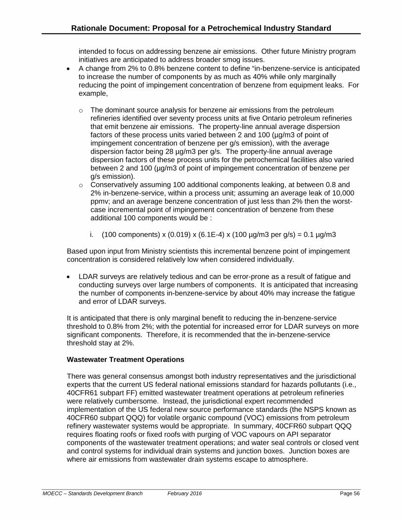
Rationale Document: Proposal for a Petrochemical Industry Standard
intended to focus on addressing benzene air emissions. Other future Ministry program initiatives are anticipated to address broader smog issues.
• A change from 2% to 0.8% benzene content to define “in-benzene-service is anticipated to increase the number of components by as much as 40% while only marginally reducing the point of impingement concentration of benzene from equipment leaks. For example,
o The dominant source analysis for benzene air emissions from the petroleum
refineries identified over seventy process units at five Ontario petroleum refineries that emit benzene air emissions. The property-line annual average dispersion factors of these process units varied between 2 and 100 (µg/m3 of point of impingement concentration of benzene per g/s emission), with the average dispersion factor being 28 µg/m3 per g/s. The property-line annual average dispersion factors of these process units for the petrochemical facilities also varied between 2 and 100 (µg/m3 of point of impingement concentration of benzene per g/s emission).
o Conservatively assuming 100 additional components leaking, at between 0.8 and 2% in-benzene-service, within a process unit; assuming an average leak of 10,000 ppmv; and an average benzene concentration of just less than 2% then the worst-case incremental point of impingement concentration of benzene from these additional 100 components would be :
i. (100 components) x (0.019) x (6.1E-4) x (100 µg/m3 per g/s) = 0.1 µg/m3
Based upon input from Ministry scientists this incremental benzene point of impingement concentration is considered relatively low when considered individually. • LDAR surveys are relatively tedious and can be error-prone as a result of fatigue and
conducting surveys over large numbers of components. It is anticipated that increasing the number of components in-benzene-service by about 40% may increase the fatigue and error of LDAR surveys.
It is anticipated that there is only marginal benefit to reducing the in-benzene-service threshold to 0.8% from 2%; with the potential for increased error for LDAR surveys on more significant components. Therefore, it is recommended that the in-benzene-service threshold stay at 2%. Wastewater Treatment Operations There was general consensus amongst both industry representatives and the jurisdictional experts that the current US federal national emissions standard for hazards pollutants (i.e., 40CFR61 subpart FF) emitted wastewater treatment operations at petroleum refineries were relatively cumbersome. Instead, the jurisdictional expert recommended implementation of the US federal new source performance standards (the NSPS known as 40CFR60 subpart QQQ) for volatile organic compound (VOC) emissions from petroleum refinery wastewater systems would be appropriate. In summary, 40CFR60 subpart QQQ requires floating roofs or fixed roofs with purging of VOC vapours on API separator components of the wastewater treatment operations; and water seal controls or closed vent and control systems for individual drain systems and junction boxes. Junction boxes are where air emissions from wastewater drain systems escape to atmosphere.
MOECC – Standards Development Branch February 2016 Page 56

Rationale Document: Proposal for a Petrochemical Industry Standard
Industry representatives indicated that they believe that some facilities are able to minimize the emission of some VOCs such as benzene from wastewater treatment operations. The Ministry responded with further review of the dominant source analysis to identify thresholds where air pollution controls for API separators and individual drain systems would be required. The following provides a summary of the review and proposal for air pollution control thresholds: • Development of an ambient monitoring threshold to require air pollution control for the
API separator:
a. Based upon information from the dominant source analysis and further dispersion modelling to determine the reduction in contaminant concentrations with distance from the API separator, it is anticipated that concentrations of benzene emitted from the API separators will reduce by a factor of two orders of magnitude over a distance of approximately one kilometer. b. Advice from Ministry scientists, indicate that an incremental annual average threshold of 0.05 micrograms per cubic metre would be a relatively negligible risk. c. Therefore, using a two orders of magnitude increase between the point of impingement of 1 kilometre distance and a point nearby to the API separator, it is recommended that an annual average measured concentration of benzene of 5 micrograms per cubic metre at a point within 100-200 metres from an API separator would serve as a threshold, above which air pollution control for the API separator would be required.
Industry representatives have also requested an alternate “benzene-in-wastewater” threshold. • Development of an alternate “benzene-in-wastewater” threshold to require air pollution
control for the API separator:
a. Based upon information from the dominant source analysis (that included a review of dispersion factors in micrograms per cubic metre per gram per second emission to the property-line) and using a maximum allowable annual average property-line concentration of 0.10 micrograms per cubic metre (the 0.05 micrograms per cubic metre threshold noted above was in-community; whereas 0.10 micrograms per cubic metre is along the property-line). b. Dividing the property-line annual average benzene concentration threshold of 0.10 micrograms per cubic metres by an average dispersion factor of 54.4 micrograms per cubic metre per gram per second emission results in a threshold annual average benzene emission from the API separator of 0.002 grams per second. c. Therefore, a combination of annual average measurements of concentrations of benzene-in-wastewater and benzene-in-oily waste skimmed from the API separator; with wastewater and oily waste flow measurements or calculations allows for development of a mass balance approach to developing an estimate of benzene air emissions from the API separator. It is recommended that this mass balance based estimate of benzene air emissions be compared, on an annual basis, to the annual average benzene emission threshold of 0.002 grams per second.
MOECC – Standards Development Branch February 2016 Page 57

Rationale Document: Proposal for a Petrochemical Industry Standard
• Development of a “benzene-in-wastewater” measurement threshold and distance
threshold to require submission of an air pollution abatement plan for drain systems and junction boxes:
a. Based upon a review of US federal rules for wastewater treatment operations, it is recommended that an air pollution abatement be submitted to the Ministry when the annual average benzene-in-wastewater concentration in a process drain exceeds 1,000 parts per million by weight; and b. Based upon information from the dominant source analysis and further dispersion modelling (e.g., contaminant concentrations are predicted to reduce by between 50 and 80 percent at a distance of 200 metres), when the junction box for a process drain is within 200 metres of a property-line.
In summary, it is recommended that, • For API separators:
o install a floating roof or fixed roof with purging of VOC vapours; or o measure in ambient air within 100-200 metres of the API separator and ensure
annual average benzene concentrations at this monitor are below 5 micrograms per cubic metre; or
o measure benzene in wastewater and oily waste skimmed from the API separator and ensure that a mass-balance developed benzene emission estimate for the API separator is below 0.002 grams per second.
• For individual process drains and junction boxes:
o install water seals or submit an air pollution abatement plan for each process drain that has a junction box air emission within 200 metres of the property-line; or
o measure benzene in wastewater for each process drain that has a junction box within 200 metres of the property-line and ensure that the annual average benzene-in-waste-water concentration is below 1,000 parts per million by weight.
It was also noted that the dissolved air flotation (DAF) device is situated downstream of the API separator and may result in residual but significant benzene air emissions. Further work is anticipated to assess the importance of this potential source of benzene air emissions at petroleum refineries. Product Loading Operations The Ministry is recommending new air pollution rules, for loading operations for product containing at least 2% by weight benzene and gasoline, that aligns with US federal requirements for petroleum refineries. Industry representatives have generally been supportive of this proposal but have requested that the applicability threshold (e.g., for each individual loading rack, 75,700 litres of gasoline per day) be translated into a three-year rolling average annual threshold because some loading racks and marine vessel terminals are only used intermittently. As a result the Ministry has adjusted the US daily applicability threshold to an annual basis (i.e., 14 million litres per year of product; three year rolling average) and proposed an annual applicability threshold for marine terminals of 1.6 billion litres per year of product; three year rolling average .
MOECC – Standards Development Branch February 2016 Page 58
Rationale Document: Proposal for a Petrochemical Industry Standard
The jurisdictional experts were hired for approximately a year starting in late April of 2015. They have not specifically identified any concerns with the above-noted approach but require additional time to complete their review. Property-Line Monitoring The Ministry is recommending the implementation of twelve property-line ambient monitors to regularly measure and report on benzene concentrations. This proposal is similar to recently finalized (i.e., December 1, 2015) updates to US federal air pollution rules for petroleum refineries. Industry representatives generally support this proposal but have asked that implementation of these requirements start at the beginning of 2018 (consistent with new US federal rules). The jurisdictional experts have not specifically identified any concerns with the above-noted approach but require additional time to complete their review.
7.3 Consideration of Input from the Aamjiwnaang and Walpole Island First Nations The Aamjiwnaang First Nation is adjacent to three of the four petrochemical facilities and within a few kilometres of the fourth facility. There are also a number of petroleum refineries nearby as well. Figure 7-1 and Figure 7-2 illustrate the location of the Aamjiwnaang First Nation relative to the petroleum refineries and petrochemical facilities in the area based on multi-source analysis for benzene and 1,3 butadiene, respectively. The Walpole Island First Nation is located south of Sarnia along the St. Clair River and at the north end of Lake St. Clair. Walpole Island First Nation is affected by water discharges from the petroleum refineries and petrochemical facilities into the St. Clair River and the lands that these facilities are situated on are traditional lands for all of the First Nations in the area. As noted above, representatives of the Aamjiwnaang First Nation and Walpole Island First Nation were invited to join the technical working group (with industry representatives) in May of 2013. A request for capacity funding was also made at that time due to the complexity of the project and the relatively large number of other requests for consultation that are regularly made to these First Nations. The Ministry worked throughout 2014 to respond to this request and was able, starting in the spring of 2015, to obtain the services of jurisdictional experts to assist both the Ministry and First Nations over a 12-15 month period. A further specific request by Aamjiwnaang for capacity funding was submitted to the Ontario Ministry of Aboriginal Affairs in April of 2015 but this request was denied in August of 2015. The following provides a summary of the meetings that the Ministry and the contracted jurisdictional experts had with the Aamjiwnaang First Nation (AFN) Environment Committee and Walpole Island First Nation (WIFN) Heritage Committee and other community focus groups between 2013 and 2015, as follows: • May 22, 2013: Met with AFN Environment Committee and WIFN Heritage Committee to
present background information with respect to the technical standards compliance approach under Ontario Regulation 419/05. Also invited participation in efforts to
MOECC – Standards Development Branch February 2016 Page 59

Rationale Document: Proposal for a Petrochemical Industry Standard
review the process to develop technical standards for the petroleum refining and petrochemical sectors.
• Dec 17, 2013 and Apr 1 2014: Met with AFN Environment Committee and WIFN
Heritage Committee to provide progress updates. • May 21-22, 2014: The Ministry met with AFN Environment Committee and WIFN
Heritage Committee and participated in focus group sessions with the seniors’ committee and mothers’ committee at the AFN; as well as a public meeting at the AFN on May 21.
• Jun 10-11, 2015: Jurisdictional experts first set of four meetings with AFN Environment
Committee and WIFN Heritage Committee. • Nov 4-5, 2015: Second set of meetings (progress update with respect to jurisdictional
review) with AFN Environment Committee and WIFN Heritage Committee. • February 16-17, 2016: Third set of meetings (progress update with respect to the
jurisdictional review) with AFN Environment Committee and WIFN Heritage Committee and the community.
MOECC – Standards Development Branch February 2016 Page 60
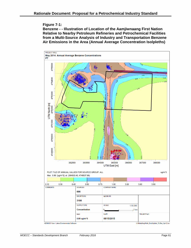
Rationale Document: Proposal for a Petrochemical Industry Standard
Figure 7-1: Benzene - - Illustration of Location of the Aamjiwnaang First Nation Relative to Nearby Petroleum Refineries and Petrochemical Facilities from a Multi-Source Analysis of Industry and Transportation Benzene Air Emissions in the Area (Annual Average Concentration Isolpleths)
MOECC – Standards Development Branch February 2016 Page 61

Rationale Document: Proposal for a Petrochemical Industry Standard
Figure 7-2: 1,3 Butadiene - - Illustration of Location of Aamjiwnaang First Nation Relative to Nearby Petrochemical Facilities from a Multi-Source Analysis of Industry and Transportation 1,3 Butadiene Air Emissions in the Area (Annual Average Concentration Isolpleths)
Annual maximum concentration: 3.07 µg/m3 at (383883, 4755887) – with HWY 40 extension
MOECC – Standards Development Branch February 2016 Page 62

Rationale Document: Proposal for a Petrochemical Industry Standard
Letters Expressing Concern from the Chief of the Aamjiwnaang First Nation The Ministry has received the following letters from the Chief of the Aamjiwnnag First Nation: • March 5, 2015: concerned that the current regulatory regime does not provide
adequate protection (particularly in terms of cumulative effects); not supportive of technical standard compliance option under Ontario Regulation 419/05; and also recommended, o Enhancement of the source pollution monitoring programs such as the
Sarnia Air Initiative; o A review by the ministry of its start-up, shut-down and malfunction policy
such that the amount of flaring is reduced; o an interagency review of the safety procedures and the overall culture of
worker safety; o an updated sulphur dioxide air standard; and o a complete jurisdictional review including an assessment of
recommendations from the US Chemical Safety Board.
The Ministry responded on June 25, 2015 indicating that the proposed technical standards for petroleum refineries and the petrochemical sector is one important component of many ministry actions aimed at improving air quality for Ontario generally and Sarnia area communities in particular. The letter also identified a plan to hire a jurisdictional expert to assist the Aamjiwnang and Walpole Island First Nations in better understanding how other jurisdictions regulate the petroleum refining and petrochemical sectors. Other initiatives such as Canadian Council of Ministers of the Environment of new federal base level industrial emission requirements; an ambient monitoring partnership between the Ministry and the Aamjiwnaang First Nation; and Ministry participation with the development of Canadian Ambient Air Quality Standards (CAAQS) for sulphur dioxide were also mentioned.
• October 20, 2015: In summary, this letter indicated that the jurisdictional expert consultant hired by the Ministry has expressed concern that (due to the relatively late starting date for the consultant) that the proposed technical standards for petroleum refining and the petrochemical sector are evolving relatively rapidly and, as a result, that Aamjinaang First Nation representatives are not able to utilize the results of the consultants’ work or findings. The letter requested an alteration of the consultation timetable and reminded the Ministry of its duty to provide meaningful consultation in good faith.
The Ministry responded in late November 2015 indicating that the Ministry was working towards a 90-day environmental bill of rights registry proposal posting, in February 2016, for the technical standard as part of efforts to improve air quality. The letter also stated that the Ministry would accept comments from the Aamjiwnaang First Nation beyond the commenting period.
• December 14, 2015: In summary, this letter was in follow-up to the October 20
2015 letter and requested meaningful consultation with respect to the technical standard; extension of the current deadline for developing the technical
MOECC – Standards Development Branch February 2016 Page 63

Rationale Document: Proposal for a Petrochemical Industry Standard
standard; for the Ministry to provide capacity funding; and a meeting with the Ontario Minister of the Environment and Climate Change.
In November of 2015, the representative of Walpole Island First Nation requested detailed site-specific information with respect to the Ministry’s dominant source analysis because of the relevance of this material in rationalizing Ministry recommendations with respect to the development of the proposed technical standard for petroleum refineries. In response, the Ministry is planning on conducting a half-day seminar, in March or April of 2016, with a demonstration of the atmospheric dispersion modelling results that supported the dominant source analysis. However the Ministry is not planning on providing model input files nor site-specific documentation pending further discussion with industry representatives.
MOECC – Standards Development Branch February 2016 Page 64
Rationale Document: Proposal for a Petrochemical Industry Standard
8. Consideration of the Ministry’s Statement of Environmental
Values
The following provides a summary of how key aspects of the Ministry’s Statement of Environmental Values are reflected in the recommendations associated with the Ministry’s development of a proposed Petrochemical – Industry Standard: • The setting of science-based air standards for benzene and 1,3 butadiene (without
consideration of technical or economic achievability) is consistent with the need for a precautionary science-based approach. The implementation of these new air standards (scheduled to come into force in July 2016) are key drivers for the need for reduced air emissions of these contaminants from Ontario’s petrochemical facilities.
• “Consideration of cumulative effects; the interdependence of air, land, water and living organisms; and the relationships among the environment, the economy and society”:
o The combined review of air emissions of benzene and 1,3 butadiene from
petrochemical facilities is consistent with considering cumulative effects . o The assessment of a range of contaminants (e.g., benzene and 1,3 butadiene)
and source types is consistent with considering cumulative effects. o The assessment of best available air pollution control technology within the
context of technical and economic feasibility and what is being achieved in other jurisdictions is consistent with efforts to consider the relationships between the environment, the economy and society.
o Completion by the Ministry of a multi-source assessment for both benzene and 1,3 butadiene air emissions where the results of this analysis suggested: for benzene, the over-lap of point of impingement concentrations
between facilities appears minimal; and for 1,3 butadiene, the over-lap of point of impingement concentrations
between facilities also appears minimal. o A multi-source assessment of benzene emissions from both industrial and non-
industrial sources was conducted and shared with the community. This multi-source assessment of benzene air emissions suggested, the combination of a multiple facilities (and transportation sources) is anticipated to increase the number of locations within the community that have measurable benzene ambient air concentrations.
o Recommendations from the Ministry in 2015-16 for new air pollution control for multiple petroleum refineries, petrochemical facilities and integrated iron and steel mills is anticipated to reduce the cumulative effect of these facilities (e.g., in Sarnia, due to benzene air emission reductions from multiple refineries and petrochemical facilities).
MOECC – Standards Development Branch February 2016 Page 65
Rationale Document: Proposal for a Petrochemical Industry Standard
9. Summary of Conclusions and Recommendations for a
Proposed Petrochemical Industry Standard Table 9-1 provides a summary of proposed recommendations for the Petrochemical – Industry Standard for benzene air emissions. Conclusions
• Ontario petrochemical facilities have been implementing voluntary efforts to limit air emissions of volatile organic compounds such as benzene and 1,3 butadiene. However, a jurisdictional review has determined that current air pollution control practices to limit benzene air emissions from petrochemical facilities in Ontario are lagging behind the requirements in the U.S.
• The jurisdictional review suggests that information from the U.S. (including U.S. Federal rules, U.S. States rules such as Texas, Louisiana and California, and assessing a 2015 U.S. EPA proposal to update air pollution rules) provides a reasonable basis to develop air pollution control requirements for Ontario petrochemical facilities.
• Current information with respect to air emissions and an analysis to identify the dominant contributors to point of impingement concentrations of benzene suggest that a focus within the proposed technical standard on storage vessels, equipment leaks, wastewater treatment operations and product loading is reasonable.
• New requirements for property-line monitoring of benzene and 1,3 butadiene are anticipated to provide important information to the Ministry, industry and surrounding communities and assist in determining if additional air pollution control requirements will be required in the future.
• Reducing risk (including an assessment of cumulative effects within the context of the
Ministry’s Statement of Environmental Values) is an important driver to the development of technical standards and new air pollution control requirements under Ontario Regulation 419/05. Specific requirements and phase-ins have been developed based upon an intention to balance the need for new air pollution control requirements with cost effectiveness17. Phase-in of requirements over a period of time is anticipated to facilitate appropriate planning, engineering and construction and to reduce implementation costs.
• Input from industry stakeholders on focusing on the most significant air emission sources; on practicality; and minimizing costs has been an important aspect of the development of the proposed technical standard.
• For 1, 3 butadiene, the proposed Petrochemical – Industry Standard should focus on the control of process fugitives from equipment leaks based on the dominant source analysis, in addition to requiring the property-line ambient monitoring.
• In an effort to develop a proposed Petrochemical – Industry Standard ahead of the phase-in of the new benzene and 1,3 butadiene air standards on July 1, 2016, Ministry work in 2015
17 Cost effectiveness is an important goal within the development of technical standards when, as in this case, the incremental risks are less than 1:10,000 in the case of carcinogens and/or less than a hazard quotient of 10 for non-carcinogens.
MOECC – Standards Development Branch February 2016 Page 66

Rationale Document: Proposal for a Petrochemical Industry Standard
and 2016 was completed at a measured but relatively expeditious pace. The intent was to complete the work so that emission reductions and regulatory certainty could be achieved as soon as possible. However, it is anticipated that additional effort by the Ministry is needed to engage and build trust with the Aamjiwnaang and Walpole Island First Nations.
• It is anticipated that, consistent with other jurisdictions such as the U.S., there are benefits to using lessons-learned (e.g., as quantified through the property-line monitoring results) to improve upon the environmental and cost effectiveness outcomes of the proposed Petrochemical Standard over a period of time. It may be reasonable to begin the process of assessing the need for updated requirements within six to eight years from the initial implementation of the technical standard in January 2018 (i.e., begin a re-assessment between 2024 and 2026).
• A process is being developed through the Air Standards/Regulation 419 External Working Group on how and when to consider updating any technical standard. Once finalized, this process will be considered for the Petrochemical – Industry Standard review.
MOECC – Standards Development Branch February 2016 Page 67
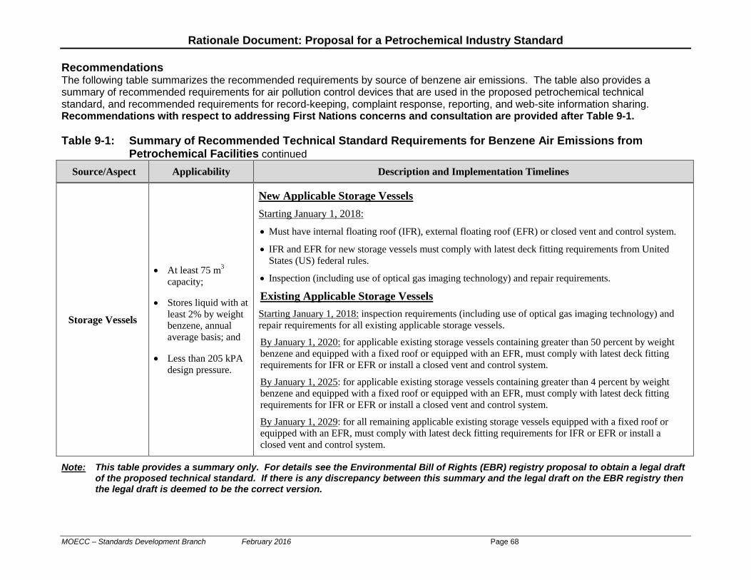
Rationale Document: Proposal for a Petrochemical Industry Standard
Recommendations The following table summarizes the recommended requirements by source of benzene air emissions. The table also provides a summary of recommended requirements for air pollution control devices that are used in the proposed petrochemical technical standard, and recommended requirements for record-keeping, complaint response, reporting, and web-site information sharing. Recommendations with respect to addressing First Nations concerns and consultation are provided after Table 9-1. Table 9-1: Summary of Recommended Technical Standard Requirements for Benzene Air Emissions from
Petrochemical Facilities continued Source/Aspect Applicability Description and Implementation Timelines
Storage Vessels
• At least 75 m3 capacity;
• Stores liquid with at least 2% by weight benzene, annual average basis; and
• Less than 205 kPA
design pressure.
New Applicable Storage Vessels
Starting January 1, 2018:
• Must have internal floating roof (IFR), external floating roof (EFR) or closed vent and control system.
• IFR and EFR for new storage vessels must comply with latest deck fitting requirements from United States (US) federal rules.
• Inspection (including use of optical gas imaging technology) and repair requirements.
Existing Applicable Storage Vessels
Starting January 1, 2018: inspection requirements (including use of optical gas imaging technology) and repair requirements for all existing applicable storage vessels.
By January 1, 2020: for applicable existing storage vessels containing greater than 50 percent by weight benzene and equipped with a fixed roof or equipped with an EFR, must comply with latest deck fitting requirements for IFR or EFR or install a closed vent and control system.
By January 1, 2025: for applicable existing storage vessels containing greater than 4 percent by weight benzene and equipped with a fixed roof or equipped with an EFR, must comply with latest deck fitting requirements for IFR or EFR or install a closed vent and control system.
By January 1, 2029: for all remaining applicable existing storage vessels equipped with a fixed roof or equipped with an EFR, must comply with latest deck fitting requirements for IFR or EFR or install a closed vent and control system.
Note: This table provides a summary only. For details see the Environmental Bill of Rights (EBR) registry proposal to obtain a legal draft of the proposed technical standard. If there is any discrepancy between this summary and the legal draft on the EBR registry then the legal draft is deemed to be the correct version.
MOECC – Standards Development Branch February 2016 Page 68
Rationale Document: Proposal for a Petrochemical Industry Standard
Table 9-1: Summary of Recommended Technical Standard Requirements for Benzene Air Emissions from
Petrochemical Facilities continued
Source/Aspect Applicability Description and Implementation Timelines
Wastewater Treatment Operations
• API Separators.
• Junction boxes, within 200 metres of the property-line and associated with process drains that are identified in an approved wastewater sampling plan.
API Separators*
For benzene air emissions from API separators, implement one of the following three compliance options for each API separator: 1. No later than July 1, 2017: submit a plan, for approval by the regional director, to measure benzene in ambient air
at a location that is between 100 and 200 metres downwind of the API separator; at a frequency of no less than once every eight days. The monitoring plan shall be implemented within three months of receiving approval from the director for the plan. If the annual average concentration of benzene is greater than 5 µg/m3 then the air pollution control requirements in paragraph 3, below, must be complied with within 18 months.
2. No later than July 1, 2017: submit a plan, for approval by the regional director, to measure the concentration of benzene in wastewater (at the inlet and outlet of the API separator); in the skim oil from the top of the API separator; and in the sludge removed from the API separator. If an estimate of benzene air emissions from the API separator (determined using a mass balance approach in conjunction with the benzene concentration and mass flow measurements for the API separator) are greater than 2 milligrams per second then the air pollution control requirements in paragraph 3, below, must be complied with within 18 months.
3. No later than January 1, 2019: Install either an internal floating roof; an external floating roof or a closed vent and control system on each API separator.
Process Drains and Junction Boxes within 200 metres of the Property-Line*
For benzene air emissions from junction boxes, within 200 metres of the property-line, that serve process drains, implement one of the following compliance options: 1. No later than July 1, 2017: submit an air pollution abatement plan, for approval by the regional director, to
minimize benzene air emissions from process drains and junction boxes. The abatement plan shall be implemented no later than January 1, 2019.
2. No later than July 1, 2017: submit a plan, for approval of the regional director, to measure benzene in wastewater from process drains that have a junction box within 200 metres of the property-line. If the annual average concentration of benzene in wastewater is greater than 100 parts per million by weight, then the abatement plan submission requirements shall be complied with.
* The Ministry is planning on publishing a technical bulletin to assist in the interpretation of the requirements for API separators, and process drains and junction boxes.
Note: This table provides a summary only. For details see the Environmental Bill of Rights (EBR) registry proposal to obtain a legal draft of the proposed technical standard. If there is any discrepancy between this summary and the legal draft on the EBR registry then the legal draft is deemed to be the correct version.
MOECC – Standards Development Branch February 2016 Page 69

Rationale Document: Proposal for a Petrochemical Industry Standard
Table 9-1: Summary of Recommended Technical Standard Requirements for Benzene Air Emissions from
Petrochemical Facilities continued Source/Aspect Applicability Description and Implementation Timelines
Product Loading
• Truck and railcar
loading racks: each loading rack that has a throughput capacity of at least 14 million litres per year of liquid product that contains at least 2% by weight benzene.
• Marine vessel loading: each marine vessel terminal that has a three year rolling average throughput capacity of at least 1.6 billion litres of liquid product that contains at least 2% by weight benzene.
Truck, Railcar Loading Racks and Marine Vessel Terminals:
• No later than January 1, 2017: ensure that the throughput of product for each loading rack and marine vessel loading berth at a petroleum refining facility is recorded.
• Applicable loading racks and marine vessel terminals must be equipped, within 18 months of the relevant record, with a closed vent system and the air emissions conveyed to an air pollution control device option (where the requirements for air pollution control devices are described in a separate portion of this table).
• Tank filling lines must be placed no higher than 10 centimetres above the bottom of the cargo tank.
• Starting July 1, 2018: only vapour tight cargo tanks can be used to load at applicable truck and railcar loading racks and at an applicable marine vessel loading berth.
Note: This table provides a summary only. For details see the Environmental Bill of Rights (EBR) registry proposal to obtain a legal draft of the proposed technical standard. If there is any discrepancy between this summary and the legal draft on the EBR registry then the legal draft is deemed to be the correct version.
MOECC – Standards Development Branch February 2016 Page 70
Rationale Document: Proposal for a Petrochemical Industry Standard
Table 9-1: Summary of Proposed Recommended Technical Standard Requirements for Benzene Air Emissions
from Petrochemical Facilities continued
Source/Aspect Applicability Description and Implementation Timelines
Equipment Leaks:
Leak-
Detection-and-Repair
(LDAR) Requirements
• Checking for and repairing leaks in the following components when they come into contact with a fluid that contains 2.0 percent by weight benzene or more: o Valves. o A pressure relief device. o A sample point. o An instrumentation system. o A connector. o Compressors and pumps. o An agitator.
• Components that are unsafe to monitor or are operated below atmospheric pressure are excluded.
• Valves with a nominal diameter less than 1.875 centimetres are excluded.
• Pumps that are equipped with a dual mechanical seal, a barrier fluid that is at a higher pressure than the operating pump pressure, and a system to alert the operator when the seal or barrier fluid have failed are excluded.
• Components that are inaccessible are excluded until January 2023.
Component Leak Survey – Assessment and Measurement of Leaks • A leak is defined as anything greater than 1,000 parts per million by volume volatile organic compounds. • Starting January 1, 2018: complete a component leak survey at least once every 4 month period (or at least
once every 12 month period if the percentage of leaking valves is less than one percent) where at least one of the surveys in a 12 month period must be conducted using a method, as described in Appendix A of the proposed technical standard, that is similar to US EPA Method 21. The other surveys in a year may use either the Appendix A method or an optical gas imaging method described in Appendix B (the Ministry is planning on publishing a supplementary technical bulletin with guidance on using optical gas imaging).
Audit of Component Leak Surveys Starting January 1, 2018: it is a contravention of the technical standard if a compliance audit determines that the percentage of leaking components is more than 50% greater than what was found in the original survey. For example, if 2.0% leaking components was found in a component leak survey then it would be a contravention of a Ministry audit subsequently found that the leak components was greater than 3.0%.
Leak Repairs • Between January 1, 2018 and January 1, 2020: identified leaks must be repaired. • Between January 1 2020 and January 1, 2023: leaks must be repaired within specified timeframes (e.g.,
within 15 days to reduce the leak below 25,000 parts per million by volume VOC for leaks over 25,000 ppmv; a further 30 days to reduce leaks below 10,000 ppmv; and a further 60 days to reduce leaks below 1,000 ppmv).
• Starting January 1, 2023: leaks must be repaired in half of the allowable time that was specified for the period between 2020 and 2023.
Delay of Repair list
Starting January 1, 2018: a leaking component may be placed on a delay of repair list (for repair at the next process unit shutdown) if the combined total of leaks on delay of repair (for components in 50% or greater benzene service) is less than 250,000 ppmv as benzene.
Note: This table provides a summary only. For details see the Environmental Bill of Rights (EBR) registry proposal to obtain a legal draft of the proposed technical standard. If there is any discrepancy between this summary and the legal draft on the EBR registry then the legal draft is deemed to be the correct version.
MOECC – Standards Development Branch February 2016 Page 71
Rationale Document: Proposal for a Petrochemical Industry Standard
Table 9-1: Summary of Recommended Technical Standard Requirements for Benzene Air Emissions from
Petrochemical Facilities continued Source/Aspect Applicability Description and Implementation Timelines
Property-line Monitoring
-
Installation of Ambient Monitors (Along or Nearby to the Property-Boundary)
• Starting January 1, 2018: ambient monitors are measuring benzene for at least 12 locations at or nearby to the property-line. The monitoring must be based upon a plan approved by the Ministry and include two-week duration samples.
• A baseline of three years of monitoring data must be developed for each monitor. If, in subsequent years, the benzene monitoring results at any monitor are statistically significantly higher than the baseline then the facility must notify a provincial officer as soon as practicable and within six months submit details of the increase; an explanation of the possible causes; and a plan to prevent any future statistically significant increases above the baseline.
• A new baseline shall be re-determined every year after the third year and the re-determined baseline becomes applicable for a monitor if the average of the new data is less than the average of the previously determined baseline.
Note: This table provides a summary only. For details see the Environmental Bill of Rights (EBR) registry proposal to obtain
a legal draft of the proposed technical standard. If there is any discrepancy between this summary and the legal draft on the EBR registry then the legal draft is deemed to be the correct version.
MOECC – Standards Development Branch February 2016 Page 72
Rationale Document: Proposal for a Petrochemical Industry Standard
Table 9-1: Summary of Recommended Technical Standard Requirements for Benzene Air Emissions from
Petrochemical Facilities continued Source/Aspect Applicability Description and Implementation Timelines
Air Pollution Control Devices
• Devices that are used to control benzene air emissions with respect to other aspects of the technical standard (e.g., benzene air emissions that are re-directed from storage vessels through a closed vent system).
Requirements for Flares that are Used as Air Pollution Control Devices for the Purposes of this Technical Standard
• Starting January 1, 2018: the flare must have a flame present (continuous monitoring to ensure a flame is present is required in the recommendations for a proposed technical standard).
• Starting January 1, 2023: o Flare tip velocity: less than 18.3 metres per second; or the log of the flare tip velocity must than,
(NHVvg + 45,182)/(103,961); NHVvg means net heating value of the vent gas in kilojoules per standard cubic metre.
o The flare combustion zone net heating value shall be less than 10,000 kilojoules per cubic metre. o The flare net heating dilution factor value shall be no less than 250 kilojoules per square metre. o Continuous monitoring for vent gas flow and composition is required.
• The Ministry is planning on publishing a technical bulletin for flares.
Requirements for Other Air Pollution Control Devices that are Used as Air Pollution Control Devices for the Purposes of this Technical Standard
• For the purposes of a proposed petroleum refining technical standard, other air pollution control devices include a carbon adsorption device, a thermal oxidizer, a catalytic oxidizer, process heaters and boilers.
• The other (non-flare) air pollution control devices shall comply with at least one of the following: o Reduction in benzene by at least 95 percent on a mass basis; o Not discharge VOCs to air in a concentration greater than 20 ppm by volume, corrected to 3 percent oxygen. o Thermal oxidizer shall attain a temperature of at least 760 oC for a residence time of at least 0.75 seconds.
Catalytic oxidizers shall attain a temperature of at least 400 oC. Continuous monitoring for temperature will be required.
o No discharge to atmosphere when the carbon in a carbon adsorber is being re-generated. • Stack testing, every two years, will be required to confirm the benzene emission reduction and/or the 20 ppm VOC
emission limit.
Note: This table provides a summary only. For details see the Environmental Bill of Rights (EBR) registry proposal to obtain a legal draft of the proposed technical standard. If there is any discrepancy between this summary and the legal draft on the EBR registry then the legal draft is deemed to be the correct version.
MOECC – Standards Development Branch February 2016 Page 73

Rationale Document: Proposal for a Petrochemical Industry Standard
Table 9-1: Summary of Recommended Technical Standard Requirements for Benzene Air Emissions from
Petrochemical Facilities continued Source/Aspect Applicability Description and Implementation Timelines
Record-Keeping;
Reporting; Complaint
Response; and Web-Site
Information Sharing
Continued
-
Record-Keeping Requirements (to be kept on-site for 5 years; 10 years for ambient monitoring)
• Starting January 1, 2018: record-keeping of the following information:
o Storage vessels: for each applicable storage vessel include an identifier; the storage vessel capacity in cubic metres; a description of the liquid stored including the percent by weight benzene; the last and next scheduled emptying of the storage vessel and the reason for the emptying; any incident that a floating roof stopped floating; the results of optical gas imaging leak surveys; the results of any rim seal gap inspections; and a description of any repairs completed on the storage vessel.
o Wastewater Treatment Operations: for each API separator, the type of air pollution control applied to the separator to reduce benzene air emissions (i.e., EFR, IFR, closed vent and control or none); an identification of the type of monitoring that is being employed for API separators without air pollution control (i.e., ambient air monitoring; or wastewater monitoring and mass balance); and the results of the monitoring for API separators without any control. For process drains with junction boxes sources of air emissions within 200 metres of the property-line, the type of benzene air emission control applied to each junction box and, if not, the results from the wastewater monitoring; and a map identifying the locations of relevant process drains and junction boxes.
o Product loading: for each truck loading rack, railcar loading rack and marine vessel terminal records of throughput of the product loaded in litres per year for the previous year; records of the type of air pollution control equipment on each loading rack and marine terminal.
o Leak Detection and Repair: Records for each applicable component including name, model number (and serial number for components installed
after January 1, 2018) and manufacturer; the date that the component was first installed; a description of the purpose; the process unit that the component is part of; whether or not the component is accessible and/or unsafe to monitor; an indication of the component’s size; and an estimate of the percentage by weight benzene that the component is exposed to.
Identification of each component on a plan. Records of leak survey monitoring results. Records of component repairs and replacement and monitoring results after repair. Records of components on delay of repair.
o Property-line Monitoring: a map showing the location of each monitor; and records of the benzene monitoring results for each property-line monitor; records of the statistical analysis and comparison to baseline monitoring data for each monitor; and records of any changes in the baseline for any monitor; and a summary of any causes to statistically significant increases in monitoring results; and actions taken to address the increases.
o Air Pollution Control Device Performance Monitoring: the results of continuous monitoring of flares and thermal and catalytic oxidizers; and the results of biannual stack testing for applicable air pollution control devices.
Note: This table provides a summary only. For details see the Environmental Bill of Rights (EBR) registry proposal to obtain a legal draft of the proposed technical standard. If there is any discrepancy between this summary and the legal draft on the EBR registry then the legal draft is deemed to be the correct version.
MOECC – Standards Development Branch February 2016 Page 74
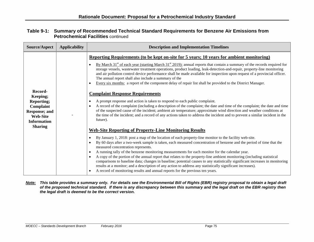
Rationale Document: Proposal for a Petrochemical Industry Standard
Table 9-1: Summary of Recommended Technical Standard Requirements for Benzene Air Emissions from
Petrochemical Facilities continued
Note: This table provides a summary only. For details see the Environmental Bill of Rights (EBR) registry proposal to obtain a legal draft
of the proposed technical standard. If there is any discrepancy between this summary and the legal draft on the EBR registry then the legal draft is deemed to be the correct version.
Source/Aspect Applicability Description and Implementation Timelines
Record-Keeping;
Reporting; Complaint
Response; and Web-Site
Information Sharing
-
Reporting Requirements (to be kept on-site for 5 years; 10 years for ambient monitoring)
• By March 31st of each year (starting March 31st 2019): annual reports that contain a summary of the records required for storage vessels, wastewater treatment operations, product loading, leak-detection-and-repair, property-line monitoring and air pollution control device performance shall be made available for inspection upon request of a provincial officer. The annual report shall also include a summary of the
• Every six months: a report of the component delay of repair list shall be provided to the District Manager.
Complaint Response Requirements
• A prompt response and action is taken to respond to each public complaint. • A record of the complaint (including a description of the complaint; the date and time of the complaint; the date and time
of the suspected cause of the incident; ambient air temperature; approximate wind direction and weather conditions at the time of the incident; and a record of any actions taken to address the incident and to prevent a similar incident in the future).
Web-Site Reporting of Property-Line Monitoring Results
• By January 1, 2018: post a map of the location of each property-line monitor to the facility web-site. • By 60 days after a two-week sample is taken, each measured concentration of benzene and the period of time that the
measured concentration represents. • A running tally of the benzene monitoring measurements for each monitor for the calendar year. • A copy of the portion of the annual report that relates to the property-line ambient monitoring (including statistical
comparisons to baseline data; changes in baseline; potential causes to any statistically significant increases in monitoring results at a monitor; and a description of any action to address any statistically significant increases).
• A record of monitoring results and annual reports for the previous ten years.
MOECC – Standards Development Branch February 2016 Page 75
Rationale Document: Proposal for a Petrochemical Industry Standard
Appendix A: Bibliography Canadian References:
1. Canadian Council of Ministers of the Environment, “Environmental Code of Practice for the
Measurement and Control of Fugitive Emissions from Equipment Leaks – PN1106, October 1993”.
2. Cheminfo for the Ontario Ministry of the Environment, “Review of the Federal Clean Air Regulatory Framework (Implications for Ontario’s Major Industrial Sectors, September 2007”.
3. SNC Lavalin for Environment Canada, “Technology and methods comparison report – Developing a Protocol for the Detection of Fugitive Equipment Leaks and Volatile Organic Compounds (VOC) and Greenhouse Gases (GHG), March 2013”.
4. SNC Lavalin for Ontario Ministry of the Environment, “Presentation – Leak Detection and Repair (LDAR) Workshop, October 18, 2012”.
MOECC – Standards Development Branch February 2016 Page 76

Rationale Document: Proposal for a Petrochemical Industry Standard
References from the United States: U.S. Environmental Protection Agency:
5. U.S. EPA, “Regulatory Impact Analysis: Synthetic Organic Chemical Manufacturing
Industry, EPA Document Number EPA-453/R-94-019, March 1994;
6. U.S. EPA, AP-42 Compilation of Air Pollutant Emission Factors, Chapter 6 – Organic Chemical Process Industry, January 1995;
7. U.S. EPA, “Final Baseline Residual Risk Assessment for MACT I Petroleum Refining Sources, January 2009”;
8. Summary of Key U.S. Regulations Affecting the Petrochemical Sector:
a. 40CFR60, subpart Kb, Standards of Performance for Storage Vessels for Volatile Organic Liquids;
b. 40CFR60, subpart III, Standards of Performance for SOCMI Air Oxidation Process Vents;
c. 40CFR60, subpart RRR, Standards of Performance for SOCMI Reactor Process Vents; d. 40CFR60, subpart VV, Standards of Performance for Equipment Leaks of VOC in the
Synthetic Organic Chemicals Manufacturing Industry; e. 40CFR60, subpart VVa, Standards of Performance for Equipment Leaks of VOC in the
Synthetic Organic Chemicals Manufacturing Industry; f. 40CFR61, subpart BB, National Emission Standards for Benzene Emissions from
Benzene Transfer Operations; g. 40CFR61, subpart FF, National Emission Standards for Benzene Waste Operations; h. 40CFR61, subpart V, National Emission Standards for Equipment Leaks (Fugitive
Emission Sources); i. 40CFR61, subpart Y, National Emission Standards for Benzene Emissions from
Benzene Storage Vessels; j. 40CFR63, subpart A, National Emission Standards for Hazardous Air Pollutants –
General Provisions; k. 40CFR63, subpart F, Organic National Emission Standards for Hazardous Air
Pollutants from the Synthetic Organic Chemical Manufacturing: General Provisions; l. 40CFR63, subpart FFFF, National Emission Standards for Hazardous Air Pollutants:
Miscellaneous Organic Chemical Manufacturing; m. 40CFR63, subpart G, Organic National Emission Standards for Hazardous Air
Pollutants from Synthetic Organic Chemical Manufacturing Industry for Process Vents, Storage Vessels, Transfer Operations, and Wastewater;
n. 40CFR63, subpart H, Organic National Emission Standards for Hazardous Air Pollutants for Equipment Leaks;
o. 40CFR63, subpart TT, National Emission Standards for Equipment Leaks – Control Level 1;
p. 40CFR63, subpart UU, National Emission Standards for Equipment Leaks – Control Level 2 Standards;
MOECC – Standards Development Branch February 2016 Page 77
Rationale Document: Proposal for a Petrochemical Industry Standard
q. 40CFR63, subpart VV, National Emission Standards for Oil-Water Separators and
Organic-Water Separators; r. 40CFR63, subpart WW, National Emission Standards for Storage Vessels – Control
Level 2.
MOECC – Standards Development Branch February 2016 Page 78

Rationale Document: Proposal for a Petrochemical Industry Standard
Appendix B: List of Stakeholders and Communities
Date Meeting Description
1 May 13, 2013 First meeting of the external technical working group comprised of Ministry staff and representatives of the Chemistry Industry Association of Canada (CIAC) and petrochemical facilities (Imperial Oil, Lanxess, Nova, Styrolution).
2 May 22, 2013 Presentations to the Aamjiwnaang First Nation Environment Committee and Walpole Island Heritage Committee. Introduced technical standard project for petroleum and petrochemical sectors.
3 Dec. 9, 2013 Meeting with external technical working group.
4 May 15, 2014 Meeting with external technical working group.
5 May 15, 2014 Presentation to the Bluewater Community Advisory Panel. Introduced technical standard project.
6 May 21-22, 2014
Presentations to the Aamjiwnaang First Nation Environment Committee and Walpole Island Heritage Committee. Progress update.
7 Nov. 5-6, 2014
Monitoring workshop at Lambton College in Sarnia. Attendance from regulators in Canada and the US; industry representatives from Canada and the US; Aamjiwnaang and Walpole Island First Nations; equipment suppliers. Workshop was co-hosted by the Ministry, the Canadian Fuels Association and the Air & Waste Management Association – Ontario Section. A brief meeting of the technical working group was held at the end of the workshop.
8 Dec. 8, 2014 Meeting with external technical working group.
9 Dec. 17, 2014 Presentations to the Aamjiwnaang First Nation Environment Committee and Walpole Island Heritage Committee. Progress update.
10 Jan. 15. 2015 Presentation to the Bluewater Community Advisory Panel. Progress update.
11 Jun 10-11/15 First of four sets of meetings between the jurisdictional experts and the Aamjiwnaang First Nation Environment Committee and the Walpole Island Heritage Committee.
12 Sep. 21, 2015 Meeting of external technical working group. Review of legal drafts of proposed technical standard.
13 Nov. 4-5, 2015 Second of four sets of meetings between the jurisdictional experts and the Aamjiwnaang First Nation Environment Committee and the Walpole Island Heritage Committee.
14 Dec. 7, 2015 Teleconference with the external technical working group
15 Jan. 12, 2016 Teleconference with the external technical working group
16 Feb. 2, 2016 Teleconference with the external technical working group
MOECC – Standards Development Branch February 2016 Page 79