back to basics web
TRANSCRIPT
8/13/2019 Back to Basics Web
http://slidepdf.com/reader/full/back-to-basics-web 1/3
WQA Educationa2009 SECTION II
Back to Basics: Water Pipe Sizing
It all revolves around a very basic equation to determinevelocity and rate of flow.
Editor’s Note: “Back to Basics” is a column that will run peri-odically in PM Engineer reviewing the basic principles of plumbing engineering.
Sizing a water piping system is relatively easy. The basic pipeflow equation is Q = VA. This equation can be converted to
By Julius Ballanco, PE, CPDOriginally published in PM Engineer Magazine , November 2007. Used with permission of the publisher.
The following article explains the role plumbing fixture counts play in determining selection of pipe material and diameter in build-ing design. As explained in WQA’s Installer’s Home Study Course , fixture counts are also used at the time a water treatment systemis specified to ensure that the new treatment system is 1) appropriate for the existing water flow rate and pressure conditions, and2) will not have an adverse effect on the operation of downstream plumbing fixtures.
Flow rate, pressure, building demand, pipe size, and fixture count calculations also become important in residential applicationswith new building additions/plumbing renovations, in commercial bids, and in industrial applications of water treatment.
Additional information on calculating and using fixture counts can be found in WQA’s Installer’s Home Study Course andCommercial Education Module 1: Commercial Sizing, Plumbing Design, and Applications.
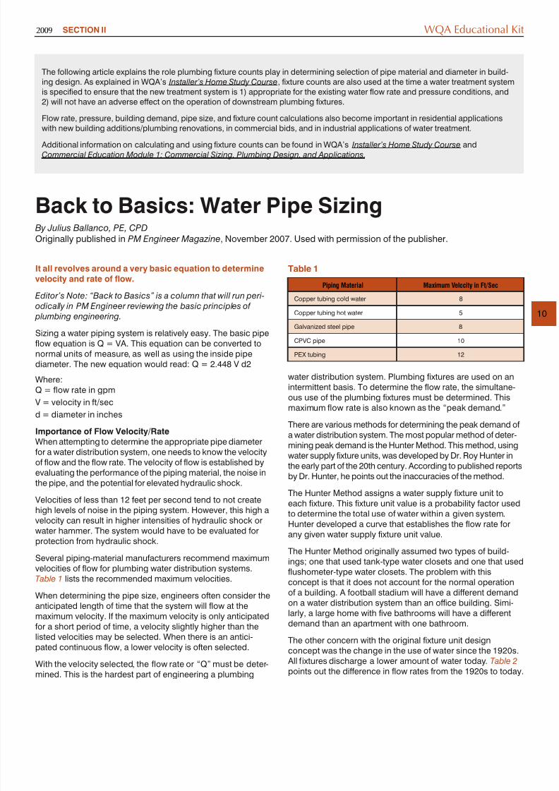
Piping Material Maximum Velocity in Ft/Sec
Copper tubing cold water 8
Copper tubing hot water 5
Galvanized steel pipe 8
CPVC pipe 10
Table 1
8/13/2019 Back to Basics Web
http://slidepdf.com/reader/full/back-to-basics-web 2/3
WQA Educational Kit
11
When Hunter did his research, a typical home had one bath-room. Today, a typical home has 3, 4, 5 or 6 bathrooms. Thesize of a typical family is also less than when Hunter performedhis studies.
These changes lead to a research project by the StevensInstitute of Technology to re-evaluate the Hunter Method. Theproject was considered somewhat controversial at the time,since many engineers wanted to do away with Hunter’smethod and come up with a completely new design concept.
About the Stevens Method
The only Plumbing Code that completely includes theStevens Method is the National Standard Plumbing Code.Both the International Plumbing Code and Uniform PlumbingCode include some of the provisions from the StevensMethod. It should be noted that all of the Plumbing Codespermit the water distribution system to be sized by acceptedengineering practice. This would allow for the use of theStevens Method.
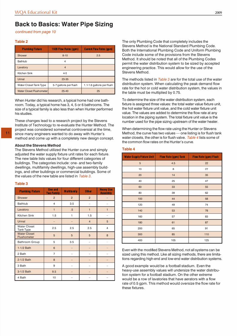
The methods listed in Table 3 are for the total use of the wdistribution system. When calculating the peak demand flowrate for the hot or cold water distribution system, the values inthe table must be multiplied by 0.75.
To determine the size of the water distribution system, eachfixture is assigned three values: the total water value fixture unit,the hot water fixture unit value, and the cold water fixture unitvalue. The values are added to determine the flow rate at anylocation in the piping system. The total fixture unit value is thenumber used for the pipe sizing upstream of the water heater.
When determining the flow rate using the Hunter or StevensMethod, the curve has two values — one listing is for flush tankwater closets, the other is for flush valve. Table 4 lists somthe common flow rates on the Hunter’s curve.
Back to Basics: Water Pipe Sizingcontinued from page 10
Plumbing Fixture 1920 Flow Rates (gpm) Current Flow Rates (gpm)
Shower 8-10 2.5
Bathtub 4
Lavatory 4
Kitchen Sink 4-5
Urinal 23-35
Water Closet Tank Type 5-7 gallons per flush 1.1-1.6 gallons per flush
Water Closet Flushometer 25-40 25
Table 2
T bl 4
8/13/2019 Back to Basics Web
http://slidepdf.com/reader/full/back-to-basics-web 3/3
WQA Educationa2009
Any sizing method needs a common sense approach forestablishing the flow rate in the piping system.
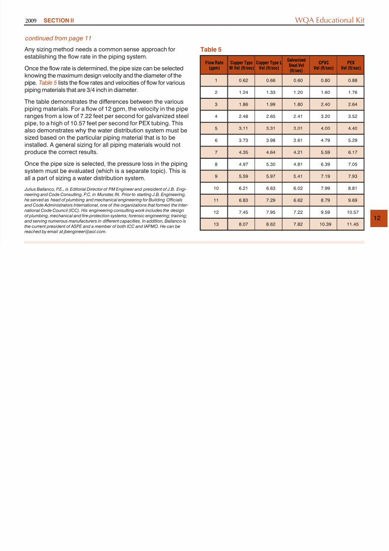
Once the flow rate is determined, the pipe size can be selectedknowing the maximum design velocity and the diameter of thepipe. Table 5 lists the flow rates and velocities of flow for variouspiping materials that are 3/4 inch in diameter.
The table demonstrates the differences between the variouspiping materials. For a flow of 12 gpm, the velocity in the piperanges from a low of 7.22 feet per second for galvanized steelpipe, to a high of 10.57 feet per second for PEX tubing. Thisalso demonstrates why the water distribution system must besized based on the particular piping material that is to beinstalled. A general sizing for all piping materials would notproduce the correct results.
Once the pipe size is selected, the pressure loss in the pipingsystem must be evaluated (which is a separate topic). This isall a part of sizing a water distribution system.
Julius Ballanco, P.E., is Editorial Director of PM Engineer and president of J.B. Engi- neering and Code Consulting, P.C. in Munster, IN. Prior to starting J.B. Engineering, he served as head of plumbing and mechanical engineering for Building Officials and Code Administrators International, one of the organizations that formed the Inter- national Code Council (ICC). His engineering consulting work includes the designof plumbing, mechanical and fire-protection systems; forensic engineering; training; and serving numerous manufacturers in different capacities. In addition, Ballanco isthe current president of ASPE and a member of both ICC and IAPMO. He can be reached by email at [email protected].
SECTION II
continued from page 11
Flow Rate
(gpm)
Copper Type
M Vel (ft/sec)
Copper Type L
Vel (ft/sec)
GalvanizedSteel Vel(ft/sec)
CPVC
Vel (ft/sec)
P
Vel
1 0.62 0.66 0.60 0.80 0.
2 1.24 1.33 1.20 1.60 1.
3 1.86 1.99 1.80 2.40 2.
4 2.48 2.65 2.41 3.20 3.
5 3.11 3.31 3.01 4.00 4.
6 3.73 3.98 3.61 4.79 5.
7 4.35 4.64 4.21 5.59 6.
8 4.97 5.30 4.81 6.39 7.
9 5.59 5.97 5.41 7.19 7.
10 6.21 6.63 6.02 7.99 8.
11 6.83 7.29 6.62 8.79 9.
12 7.45 7.95 7.22 9.59 10
13 8.07 8.62 7.82 10.39 11.
Table 5