bachelor ofengineering (hons) (electrical and electronics
TRANSCRIPT

Wall Climbing Robot
by
Mazhar Azrin bin Jamaludin
6446
Final Report
Bachelor of Engineering (Hons)
(Electrical and Electronics Engineering)
December 2008
Universiti Teknologi PETRONASBandar Seri Iskandar
31750 Tronoh
Perak Darul Ridzuan

Approved:
CERTIFICATION OF APPROVAL
Wall Climbing Robot
by
Mazhar Azrin Bin Jamaludin
A project dissertation submitted to the
Electrical & Electronics Engineering Programme
Universiti Teknologi PETRONAS
in partial fulfillment of the requirement for the
Bachelor of Engineering (Hons.)
(Electrical & Electronics Engineering)
AP DR. Mohd Noh Bin Karsiti
(Project Supervisor)
UNIVERSITI TEKNOLOGI PETRONAS
TRONOH, PERAK
December 2008
n

CERTIFICATION OF ORIGINALITY
This is to certifythat I am responsible for the work submitted in this project,that the
original work is my own except as specified in the references and acknowledgements, and
that the original work contained hereinhave not been undertaken or done by unspecified
sources or persons.
Mazhar Azrin Bin Jamaludin
111

ABSTRACT
This report basically discusses the preliminary research done and basic understanding of
the chosen topic, which is Wall Climbing Robots. Theobjective of this project is to develop
of robot manipulator capable of ascending glass wall to do cleaning duties. The operation
of the wall climbing robot in this project will be based on the pneumatic conceptthat is the
suction of air to make robot can move along the vertical glass. This project will require a
program using Programmable Logic Controller (PLC) to be the controller to its movement.
The PLC ladder program will execute a sequence automatically according to the pre
defined sequence of robot motion.
IV

ACKNOWLEDGMENTS
My gratitude to Allah S.W.T for His blessing towards the completion of this Final Year
Project.
In Completing this Final Year Project, I would like to acknowledge the important
contribution of the following individuals and group for the help and guidance:
1. Dr. Mohd Noh B. Karsiti (Final Year Project Supervisor)
2. Mr Azhar b. Zainal Abidin
3. EE Final Year Project Committee
I would also like to express my gratitude to all other persons that had involved directly or
indirectly in this project especially to the fellow colleagues for the assistance and
encouragement
v

LIST OF FIGURES
Figure 1 PLC overall view
Figure 2 The Project Flowchart
Figure 3 The systematical Approach of Control System DesignUsing PLC
Figure 4 The Flowchart for Prototype Construction Process
Figure 5 The Configuration for the Climbing Robot Control System
Figure 6 The Connection Setup between PLC and the Electropneumatic System
Figure 7 Basic climbing design, the step
Figure 8 The sketch of climbing robot
Figure 9 Orthographic Drawing of Wall Climbing Robot Body
Figure 10 Simulation of Pneumatic Equipment
Figure 11 Main body of Wall Climbing Robot
Figure 12 Another view of Wall Climbing Robot
Figure 13 The Valves and Pressure Regulator placed Separately form the Wall
Climbing Robot
VI

LIST OF TABLES
Table 1 Assignments of inputs and Outputs
vn

CHAPTER 1
INTRODUCTION
1.1 Background of Study
Both automation and robots are two closely related technologies that are connected
with the use and control of production operation. A robot can be defined as a machine that
consists of joined links. Programmable controller and precision actuators can be used to
articulate these joined links to desired position so that they can perform a variety of tasks.
Robots are available in a form of simple devices to very complex and intelligent system by
virtue of added sensors, computers and special features. There are several hundred types
and models of robots, which are classified by their intended application. This includes
industrial, laboratory, mobile, military, security, service, hobby, home and personal robots.
These robots come in a wide range of shapes, sizes , speed, load capacities and other
characteristics. The robot would have wide application in the industry. This includes the
maintenance works, delivery and wall painting. Since the main function of this robot is to
do the climbing job, the stability reliability and durability analysis of this robot is of main
concern.
In this project , the climbing robot uses pneumatic concept and controlled by
Programmable Logic Controller (PLC). This project is divided into two part, those are the
software development and the hardware implementation. The PLC program being
developed is used to control the movement of the robot. The movement of the robot is
based on the pneumatic concept whereby pneumatic components would also be the basic
constituents of the robot structure.

Specifically , an industrial robot has been described by the International Standards
Organization (ISO) as follows:
" A machine formed by a mechanism, including several degrees of freedom, often having
the appearance of one or several arms ending in a wrist capable of holding a tool, a work
piece, or an inspection device. In particular, its control unit must use a memorizing device
and it may sometimes use sensing or adaptation appliances to take into account
environment and circumstances. These multipurpose machines are generally designed to
carry out a repetitive function and can be adapted to other function.' (James G. Keramas,
1999)
The robot to be designed in this project is a climbing robot and could be classified
as a service robot. Particularly, this project is regarding on the design and implementation
of a climbing robot by mean of programmable logic controller (PLC) and electro
pneumatic system. Nowadays, there are many esearches and projects conducted on
climbing robot. Therefore, many types of climbing robot existed in today's world like the
wall climbing, surfclimbing , space elevator and rope climbing robots. These robots, which
are available in various sizes and shapes, were designed to do various tasks like the wall
inspection , bridges inspection, painting as well as space elevating. The robots make use of
various kinds of concept and their structures were built using motors, servo controller ,
microchip and sensors. Climbing robots developed today are like the Gecko Wall Climbing
Robot, Quadruped Wall Climbing Robot Ninja 1 and Ninja 2, ROMA (Multifunctional
autonomous self - supported climbing robot), Space Elevator Ribbon Climbing Robot,
Robosense (Bridges Inspection Robot), Sloth (Rope Climbing Robot) and SURFY (Surface
Climbing Robot).
1.2 Problem Statement
Cleaning building glass job sometimes involves patching up work like at the top of
a tower, building or pole. This works usually need man to climb up the tower or pole in
order to the cleaning job. This works are dangerous and exposed the person to the risk of
falling down. Therefore, the idea of designing this robot exists from observation of this

situation. Intelligently designed, this robot might be the solution to eliminate the need of
the manpower to do the climbing job.
The idea of this project also comes from the fact that the programmable logic
controller (PLC) has wide application in automated control system. The applicability of the
controller to be integrated with the electro-pneumatic system is also true. Therefore, this
give the idea of building the climbing robot bymeans of this two subjects.
1.3 Objectives and Scope ofWorks
The objectives of this project are as follow:
(a) To design a wall climbing robot capable of ascending glass to do cleaning duties.
(b) To implement the hardware for this robot that used pneumatic components as the
basic constituents.
(c) To design a PLC program asthe controller for the operation of the robot.
(d) To build the prototype ofthe robot that could show the operation concept ofthe
robot.
This Project involves two parts, which are the creation of the PLC ladder program and
the hardware implementation of the robot. In the first part of the project, the student is
required to construct a basic ladder program using window based programming software to
show the fundamental concept of the robot movement. The concept has to be shown by
integrating the PLC to the electropneumatic system and using the on board pneumatic
components to represent the robot parts. The second stage of the project involves defining
the robot structure, preparing detail design, locating the components and building the
prototype. The prototype to be constructed should at least showing the fundamental
principle of the robot movement. The robot design subjected to changes for future
improvement of its stability, reliability anddurability.

TABLE OF CONTENTS
CERTIFICATION OF APPROVAL II
CERTIFICATION OF ORIGINALITY Ill
ABSTRACT IV
ACKNOWLEDGMENTS V
LIST OF FIGURES VI
LIST OF TABLES VII
CHAPTER 1 1
INTRODUCTION I
1.1 Background of Study 1
1.2 Problem Statement 2
1.3 Objectives and Scope of Works 3
CHAPTER 2 4
LITERATURE REVIEW 4
2.1 Programmable logic controller 4
2.1.1 Basic Operation of PLC 6
2.3 Pneumatics andhydraulics 6
2.3.1 Electropneumatic valves 7
CHAPTER 3 8
METHODOLOGY 8
3.1 Project Flowchart 8
3.2 Programmable Logic Controller 10
3.2.1 The Procedure for Creating PLC Ladder Program 12
3.3 Prototype Construction Process 14
3.3.1 Prototype components 15
CHAPTER 4 18
vm

RESULT AND DISCUSSION 18
4.1 Software Development for Climbing Robot 18
4.1.1 Software Analyiss 18
4.2 Basic Configuration of the Climbing Robot Control System 20
4.3 Climbing Mechanism 22
4.3.1 Climbing Simulation 25
4.3.2 Hardware Implementation of Climbing Robot 27
4.3.2 Hardware Analysis 28
CHAPTER 5 30
CONCLUSION AND RECOMMENDATIONS 30
5.1 Conclusion 30
5.2 Recommendations 31
REFERENCE 32
IX

CHAPTER 2
LITERATURE REVIEW
2.1 Programmable logic controller
Programmable logic controller (PLC), have been used in industry since 1969 and since this
time they have become firmly established as the most popular means of controlling the
operation of plant and machinery. They have of course evolved in terms if hardware and
software. Since around 1974 microprocessors have beenused as the very 'brain' of the PLC
and this , along with the advances in electronic circuits and components, has enabled
cheaper, smaller, more powerful and reliable units to be developed. Similarly and
sometimes available, communication features, the means of documenting programs and
faults finding have all been enhanced sothat modern day PLC's are vastly superior to those
encountered in the 1970s.
A PLC- controlled system consists of:
• A power supply
• An input device such as a limit switch, push button, sensor
• An input module, which is part of the PLC
• A logic unit, which is the "brains" within the PLC
Power Supply
The power supply provides power for the PLC system. The power supply provides internal
DC current to operate the processor logic circuitry and input/output assemblies. Common
power levels used are 24V DC or 120 VAC.

Processor (CPU)
The processor, central processing unit, or CPU is the "brain" ofthe PLC. The size and type
of CPU will determine things like: the programming functions available, size of the
application logic available, amount of memory available, and processing speed.
Understanding the CPU can be a complex subject and we will tackle that inother articles.
Input / Output Assembly
Inputs carry signals from the process into the controller, they can be input switches,
pressure sensors, operator inputs, etc. These are like the senses and sensors ofthe PLC.
Outputs are the devices that the PLC uses to send changes out to the world. These are the
actuator the PLC canchange to adjust or control the process - motors, lights, relays, pumps.
Many types of inputs and outputs can be connected to a PLC, and they can all be divided
into two large groups - analog and digital. Digital inputs and outputs are those that operate
due to a discrete or binary change - on/off, yes/no. Analog inputs and outputs change
continuously over a variable range - pressure, temperature, potentiometer.
Programming Device
The PLC is programmed using a specialty programmer or software on a computer that can
load and change the logic inside. Most modern PLCs are programmed using software on a
PC or laptop computer. Older systems used a custom programming device.

2.1.1 Basic Operation of PLC
The operation of the PLC system is simple and straightforward. The Process or CPU
completes three processes:
1.scans, or reads, from the input devices
2.executes or "solves" the program logic, and
3.updates, or writes, to the output devices.
Iii]>iitTable
Input system
Programmer
iCPU:
ProgramLogic
Memory /Datastorage]
Output Table
OutputSystem
Figure 1 : PLC overall view
2.3 Pneumatics and hydraulics
As described in section 2.1, the PLC is the controller or 'brain' if the plant or
machine that is being controlled. Pneumatic actuators are used in profusion within
automatic an semi- automatic plant and machines and so it is well worth understanding the
basic operation, symbols and control problem of electropneumatic systems. An

understanding of this subject will enable me to create suitable ladder diagrams, convert
these into a PLC program and thus control such systems.
2.3.1 Electropneumatic valves
The essence of electropneumatic circuits is the electropneumatic directional control valve
which acts as a 'switch' to direct compressed air to each side of pneumatic actuators or to
different actuators.
The five-port, two position solenoid valve is the most commonly used valve. It is called
'five-port' because there are five drilled and tapped ports in the body of the valve. 'Two
position' because the directional spool within the valve has two positions and 'solenoid'
because the spool is moved back and forth by the electromagnetic actuation solenoid.
The purpose of the five port valve is to extend and retract a pneumatic piston in response to
an electric signal being supplied to the appropriate solenoid.

CHAPTER 3
METHODOLOGY
3.1 Project Flowchart
The flowchart of the project is as shown in figure 3.1. This project started with the
literature research via internet and books on the PLC and the procedure in creating ladder
program. Therefore, the knowledge on the proper steps of designing the ladder program is
important.
After ladder program is being constructed, it has to tested using training kit and output
indicators. Once the program is verified, the simulation of the program to the electro
pneumatic system. The construction of the robot unit tool placewhen the workability of the
whole system is proved.

Literature research
• Internet
• Books
Design PLC program
Test and Troubleshoot the
Connect PLC to the pneumatic system
Test and troubleshoot the
whole system
Construct the unit
Stability testing and design improvement
Figure 2: The Project Flowchart

3.2 Programmable Logic Controller
The Programmable Logic Controller is chosen in this project because of its
reliability in accomplishing from simple to complicated control tasks. The PLC is a
programmable controller that exists from the rapid advancement of technology in control
system. In an automated control system, the PLC is commonly regarded as the heart of the
control system. With a control application program (stored within the PLC memory) in
execution, the PLC constantly monitors the state of the system through the field input
devices feedback signal. It will the base onthe program logic to determine the course ofthe
action to be carried out at the field output devices. The PLC may be used to control simple
and repetitive task, or a few of them may be interconnected together with other host
controllers or host computers through a sort of communication network, in order to
integrate the control of a complex process.
There are two types of PLCs: those are the integrated and modular PLC. An
integrated PLC is PLC that is integrated into one single unit. IT sometimes called the
shoebox or brick PLC because of its small size. This type of PLC is the most economical
option if it could provide all the capabilities that a user needs. Allen- Bradley's Micrologiz
1000, Siemen's S7-100 and OMRON's CPM1 are typical but reasonably powerful
integrated PLCs. Most PLCs of this type have a built in 24V dc power supply to drive
typical sensor. On the other hand, modular PLCs consist of optional components required
for a more complex control application as selected and assembled by the user.
A PLC consists of a Central Processing Unit (CPU) containing and application
program and input/output interfaces modules, which is directly connected to the field I/O
devices. The program control the PLC so that when an input signal from an input device
turns ON, an appropriate response is made. The response normally involves turning ON an
output signal to some sort of output devices.
Intelligence of an automated system is greatly depending onthe ability of a PLC to
read in the signal from various types of automatic sensing and manual input field devices.
10

Push buttons, keypad and toggle switches, which form the basic man- machine interface,
are type of manual input devices. On the other hand , for detection of work piece,
monitoring of moving mechanism, checking on pressure and many others, the PLC will
have to tap the signal from the specific automatic sensing devices like proximity switch and
limit switch.
The sensors and actuators are connected to the PLC via the input/output module
(I/O modules). The I/O module normally isolates the low-voltage, low currents signal that
the PLC internally uses from the higher-power electrical circuits required by the sensors
and actuators. The I/O modules include the digital I/O modules and analog I/O modules,
miscellaneous intelligent I/O modules and communication interface modules. The function
of each I/O module are as discussed below:
1. Digital I/O modules- used to connect the PLC to sensors and actuators that can only
switch on and off.
2. Analog I/O modules- used to connect the PLC sensors that can provide electrical signals
that are proportional to the measured value or to actuators that vary their output
proportional with the electrical signals received from an output analog module.
3. Miscellaneous intelligent I/O modules- Has its own built-in microprocessor and memory
and this I/O module is designed for special purposes such as counting high frequency
signals.
4. Communication interface modules - Handle the exchange of data via a communication
link.
11

3.2.1 The Procedure for Creating PLC Ladder Program
The systematic operationprocedure that are applied in the creationof the PLC ladder
program are as discussed below:
1. Define the robot sequence of operation.
The first step in the procedure is to decide what type of equipment or system
involved in the robot designthat is to be controlled. In this case, the input devices
constantly monitor the movement of the controlled system and give a specified
condition as well as sending a signal to the programmable controller. In response,
the programmable controller gives outputs in term of signal to the external output
devices that control the movement of the controlled systems. Generally, the
sequence of operation can be described by a flowchart of timing diagram.
2. Assignment of Inputs and Outputs
After determining the sequence of operation, the external input and output devices
to be connected to the PLC must be specified. In this project, the external input to
the PLC is toggle switch whereas the outputs are the electro-pneumatic valves. The
input and output devices are then being assigned numbers corresponding to the
input and output number of the particular programmable controller. The actual
wiring will follow the numbers of the particular programmable controller. The
assignment of inputsand outputsmust be performed before the ladderprogram is
created. This is because the assigned number will dictate what is the precise
meaning of the contacts in the ladder program.
12

Define the requirement of thecontrolled system
List input and output points to therespective I/O points of the PLC
Draw timing diagram base on themechanism
Translate the timing diagram intoladder program
Programmed the designed ladderdiagram into PLC
Alter the programaccordingy
Simulate the
program anddebug the software
Connect all the input and outputdevices to PLC
Check all inputs and outputconnections
Test run Program
EditingSoftware
Systematically document alldrawing
End
Figure 3: The systematical Approach of Control System Design Using PLC
13

3.3 Prototype Construction Process
The prototype construction process involved several steps as described inthe flowchart
below.
Define the detail structure of the
robot
•>r
Locate components to be usedto build the prototype
"
Prepare the detail design.- the drawing and sketching should include the correctdimensions for each and every part of the robot.
i '
Construct the prototype
Figure 4: The Flowchart for Prototype Construction Process
14

3.3.1 Prototype components
The Climbing Robot works based on the pneumatic concept and uses electro
pneumatic components as the main parts for its structure. These include the elector-
pneumatic valves and cylinders, toggle switch, pressure regulator and pneumatic tubes.
Principally, the pneumatic controls are designed to control and directthe air stream through
an air circuit. The regulating valve is usually the first control through which the air stream
passes as it enters the circuit. Regulated air pressure flows from this valve on the master
control valve. The master control valve is a directional control either the three way or four
way type.
The three-way type has three ports - an inlet, an exhaustand a cylinder port. The four- way
type has four ports - an inlet, an exhaust and two cylinder ports. The electropneumatics
system is a systemthat uses the fundamental of pneumatic controls but also needs electrical
energy. The electro- pneumatic valve usually equipped with solenoidwherebythe electrical
energy would be needed to activate the valve.
3.3.1.1 Single Acting (SA) Cylinder (Spring Extend)
SA cylinders (spring extend) are used whenpneumatic energy is required only to retract the
rod. The spring force will allow the rod to extend. This force is opposed to the rod
retraction and must therefore be considered when calculating the diameter of the cylinder.
SA cylinders are usually' controlled by a 3/2 directional valve. In this project, the single
acting cylinders are mounted as a part of the robotbody. During the climbing process, these
cylinders will act as the leg of the robot, it will push and pull the suction cup against the
glass wall.
15

3.3.1.2 Pneumatic Slider
Pneumatic Slider are used when pneumatic energy us required in both directions of the
slider movement. The areas on which pressure is applied are not equal on both sides, there
will be a difference in speed depending whether the rod is extend or retracting. In this
project the pneumatic slider are mounted as a main part of the robot body. During the
climbing process, these slider will push upward or downward the robot against the wall.
3.3.1.3 Filter Regulator Gauge
The pressure regulator regulates compresses air to be supplied to the pneumatic cylinders.
Normally , 24 psi or 2 bar pressure is supplied to the system. However, the pressure could
be increased up to 8 bar provided that it does exceed the pressure rating of the valves.
3.3.1.4 Pneumatic Tube
The pneumatic tubes linlc the pressure from the pressure regulator to the electro- pneumatic
valve and from the electro- pneumatic valve to the single acting cylinders and pneumatic
slider.
3.3.1.5 Suction Cup
A suction cup is a device, usually made of rubber or plastic, that sticks to smooth,
nonporous surfaces. They are usually used to attach objects together with the use of
suction. Upon pressing the suction cup to a surface, the air pressure inside is drastically
reduced. The relatively higher atmospheric pressure outside prevents the cup from lifting
off the surface; friction does the rest of the work. In this project, the suction cup will be the
main component for the robot to stick to the wall.
16

3.3.1.6 Air ejector
Ejector is a pump like devices uses the Venturi effect ofa converging-diverging nozzle to
convert the pressure energy of a motive fluid tovelocity energy which creates a low
pressure zone that draws in and entrains a suction fluid and then recompresses the mixed
fluids by converting velocity energy back into pressure energy. This phenomenon will
create a vacuum spaces, that will suck all the air out. Inthis project, ejector are used to suck
all the air inside suction cup , and create a vacuum so that the robot can stick tothe wall.
17

CHAPTER 4
RESULT AND DISCUSSION
4.1 Software Development for Climbing Robot
The Climbing Robot software was written in the form of PLC ladder program using Omron
Cx- Programmer software. The systematic approach for control system design using PLC
was applied in order to construct the ladder program. The complete ladder program for the
climbing robot is as in Appendix.
4.1.1 Software Analysis
In the ladder program, three inputs and six outputs are used. Each output represent an
electropneumatic valve. Note that each electropneumatic valve is connected to pneumatic
cylinders, pneumatic sliders and suction cups. Therefore the output activate the components
using the valve. The address for each input ,outputand virtual output are as in Table 1.
18

Table 1 Assignments of inputs and Outputs
Address Variables Components Description
000 Start Switch Input
001 Reset Switch Input
003 Stop Switch Input
10000 A Suction Cup Output
10002 B Suction Cup Output
10003 Cup Pneumatic Slider Output
10004 Cdown Pneumatic Slider Output
10005 Da Single Acting
Cylinder
Output
10006 Db Single Acting
Cylinder
Output
20000 Loop -Virtual Output
20001 Offcup -Virtual Output
20002 Offcdown -Virtual Output
Timers are the main components in the ladder program. The timers are used because there
is time delay between the operation ofeach ofthe pneumatic components. The timer will
control the triggering time for each output. One timer is needed to activate each output and
another one to deactivate the output.
19
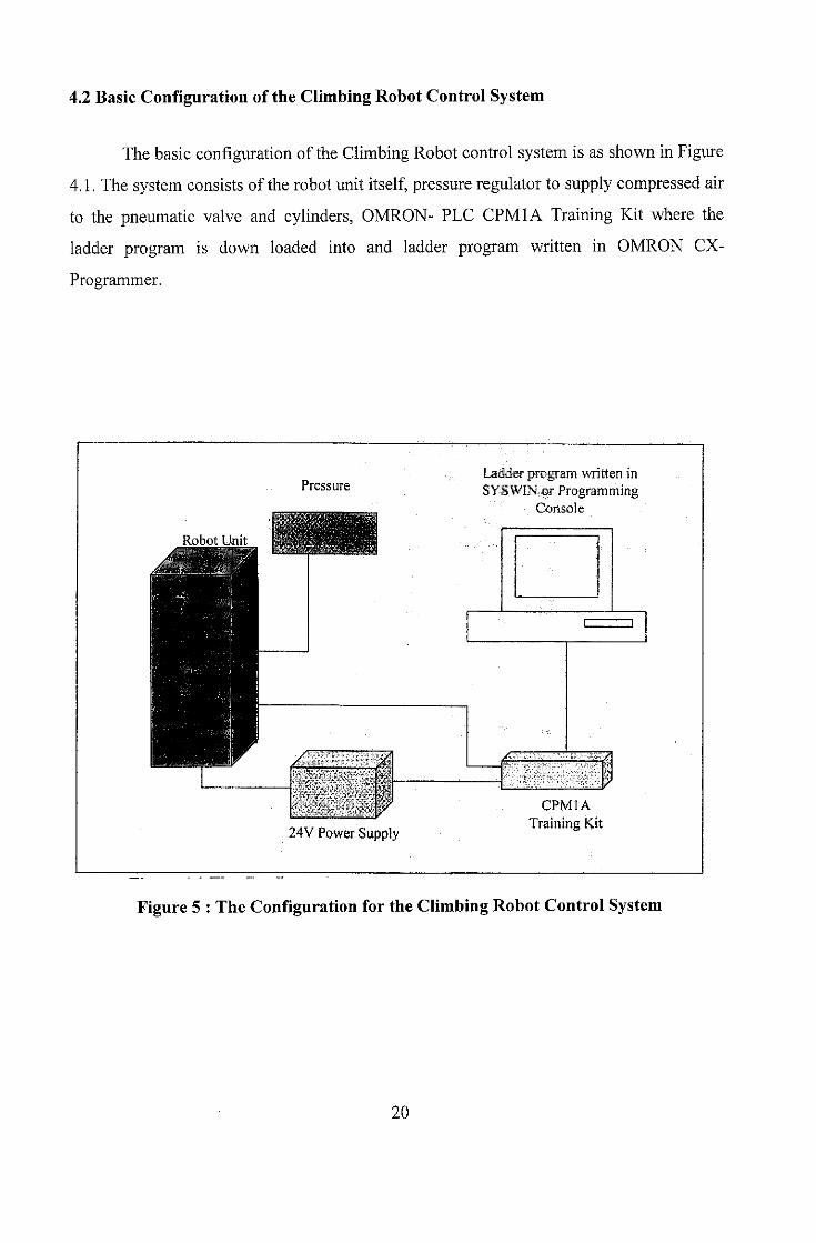
4.2 Basic Configuration of the Climbing Robot Control System
The basic configuration of the Climbing Robot control system is as shown in Figure
4.1. The system consists of the robot unit itself, pressure regulator to supply compressed air
to the pneumatic valve and cylinders, OMRON- PLC CPMIA Training Kit where the
ladder program is down loaded into and ladder program written in OMRON CX-
Programmer.
Pressure
Robot Unit
24V Power Supply
Ladder program written inSYSWIN or Programming
Console
CPMIA
Training Kit
Figure 5 : The Configuration for the Climbing Robot Control System
20

The wiring connection between the OMRON PLC CPMIA Training Kit tothe
electropneumatic system is as shown in figure 4.2 A switch, which act as input tothe
system is connected to the CPMIA input port. This switch links the CPMIA to the 24V dc
power supply. This 24dc power supply is needed as the power source for the pneumatic
system. Both COM input and COM output ofthe PLC has to be connected to power source.
Connecting the directional valve to the PLC output port atone end and ground at the other
endcompletes the wiring setup of the whole system.
CPMIA
Training KitDirectional Valve
Toggle switch
^ Input PLC Output PLC
Com output
+
COM input
24V Power Supply
Figure 6 :The Connection Setup between PLC and the Electropneumatic System
21
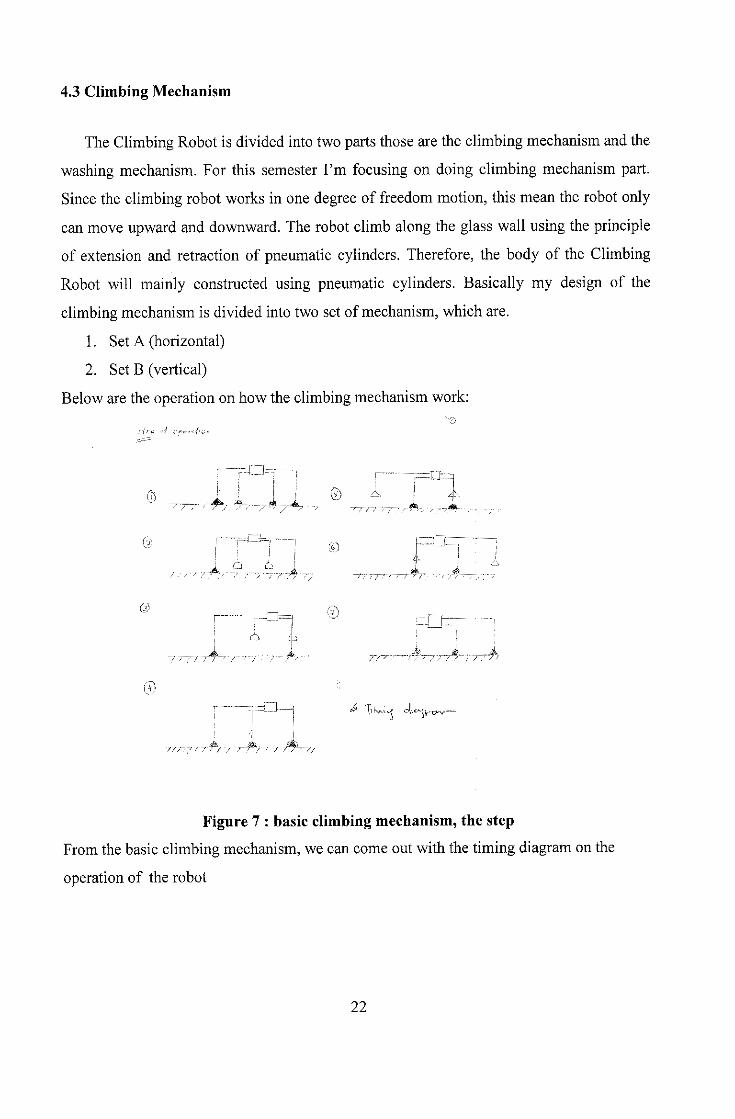
4.3 Climbing Mechanism
The Climbing Robot is divided into two parts those are the climbing mechanism and the
washing mechanism. For this semester I'm focusing on doing climbing mechanism part.
Since the climbing robot works in one degree of freedom motion, this mean the robot only
can move upward and downward. The robot climb along the glass wall using the principle
of extension and retraction of pneumatic cylinders. Therefore, the body of the Climbing
Robot will mainly constructed using pneumatic cylinders. Basically my design of the
climbing mechanism is divided into two set of mechanism, which are.
1. Set A (horizontal)
2. Set B (vertical)
Below are the operation on how the climbing mechanism work:
% I : I I Q) A. | A.
ro
O f-i
0) „ &
A-?-/—;/
1 & \y*X-J oi^s^ty-c
•//,• V' •' r> / / T-' •' / •/v'/ //
Figure 7 : basic climbing mechanism, the step
Fromthe basic climbing mechanism, we can comeout with the timing diagramon the
operation of the robot
22

^p
bA
C h/viDfV h
Legend:
A: Suction cup Set A, horizontal
B: Suction cup Set B, vertical
C: Pneumatic Slider
D: Pneumatic cylinder
23

Figure 8 : The sketch of Climbing robot body and its dimension
;To p View t • M r
1
""!.. i-
Front View
V1!
r
Side View
-
Figure 9 :Orthographic Drawingofwall climbing robot body
24

Based onthe figure 4.1, we can defined the basic movement of the robot
Step of Operation
1. Suction CupA and Suction Cup B stickto the wall
2. Suction Cup Arelease meanwhile Suction Cup B still on the same position
3. Pneumatic D1 pull Suction Cup A, the Slider C move upward.
4. Pneumatic Dl push Suction Cup Ato the wall, the Suction Cup A stick tothe
wall.
5. Suction Cup Brelease meanwhile Suction Cup Astill on the same position
6. Pneumatic D2 push Suction Cup Boffthe wall, and the Slider C move
Downward.
7. Middle pneumatic D2 pull Suction Cup Bback to the wall, The Suction Cup B
stick to the wall.
4.3.1 Climbing Simulation
Based onthe developed PLC ladder Diagram program that the author have working
on. The author move on with a simulation of the pneumatic basic component to see the
connection of the robot, the timing of the program and to understand more on the
mechanical part ofthe project. After the simulation being done, the author need to do some
adjustment to the PLC ladder program. Below are the picture ofthe equipment being usedduring the simulation. Appendix 1 show the whole PLC ladder diagram code for this
project.
25

Figure 10 : Simulation of Pneumatic Equipment
26

4.3.2 Hardware Implementation of Climbing Robot
The climbing robot was designed to be completely made of aluminium ; so that the
structure is strong enough and also lighter to perform the desired climbing job. The robot
was built based on the design previously prepared.
The components that will work the prototype out are listed below:
(a) 4 units of Single Acting Cylinders (Spring extend)
(b) 6 units of directional valve
© 1 unit of pneumatic sliders
(d) Pressure Regulator
(e) Pneumatic Tubes
(!) 8 units of Suction Cups
(g) 2 units of ejectors
Each component used to build the robotbody has its own function that acts together ini
order to perform the climbing job.
Figure 11: Main body of Wall Climbing Robot
27

Figure 12: Another view of Wall Climbing Robot
4.3.2 Hardware Analysis
In designing the hardware, its stability and reliability is of main concern. This is to
ensure that the robot could carry out itsjob properly. The Robot was designed such that the
structure is strong and stable enough throughout the climbing process. In order to do this,
the material used has to be carefully selected and the structure has to be appropriately
fabricated. Aluminium was selected for this project, the material are strong and also light.
To mountthe part the authorused nut and bolt.
Nut and bolt being used
28

In Addition to the pneumatic cylinders, pneumatic slider and suction cups, the wall
climbing robot also uses electropneumatic valves to control pressure to be supplied to the
cylinders. In order to reduce the size of the robot, the valves and pressure regulator are
placed separately from the robot body itself. Therefore pneumatic tubes ofadequate length
are required to link thepressure from the valves to the cylinders.
Figure 13: The Valves and Pressure Regulator placed Separately form theWall
Climbing Robot
29

CHAPTER 5
CONCLUSION AND RECOMMENDATIONS
5.1 Conclusion
The Wall Climbing Robot was designed and will be implemented in this project
operates based on the pneumatic concept. In this project, the movement of the robot is
controlled by a PLC ladder program written in OMRON CX-Programmer This ladder
program was constructed based on the robot sequence of operation defined earlier. In this
project, it has been experimentally shown that the PLC ladder program is reliable to control
the operation of this robot.
The robot hardware was implemented by using pneumatic components as the basic
constituents. The prototype of the robot constructed in this project was able to show the
basic principle of the robot movement. This shows that the general objective of the project,
that is to design and implement a robot that works based on pneumatic concept and
controlled by programmable logic controller (PLC) was achieved. However, the structure
of the robot has to be further refined in order to ensure the stability and reliability of the
robot itself. This is because it has been observed that the steadiness and robustness of the
robot is greatly depending on the structure or design and the material usedto buildthe unit.
Furthermore, it was verified that PLC is able to control the movement of the every single
part of the robot prototype built in this project. In conclusion, the robot designed and
implemented in this project had proved that the integration between PLC and pneumatic is
potential in designing and fabricating a new type of climbing robot.
30

5.2 Recommendations
A few suggestions for improvement to the hardware and software of the robot are as listed
below:
1. Since the climbing robot has wide application in maintenance work and industry, it
is suggested that the robot is equipped with the sensors. The functions ofthe sensors
are to detect obstacle and this could be implemented by using infrared sensor. The
additional sensors incorporated to the climbing robot will make it more reliable to
be applied in industries.
2. In order to perform further stability analysis to the climbing robot, it is
recommended that a feedback signal to be used. Therefore, the PID controller could
possibly be implemented to the climbing robot in order to do proper stability
analysis as well as increasing its stability.
3. The usage of more lighter pneumatic components can make the robot climb faster
and to ensure that it more stable.
31

Reference
[1] K.Clements-Jewery, W. Jeffcoat, The PLC Workbook, Prentice Wall
[2] Gary Dunning, Introduction To Programmable Logic Controllers, Delmar Publishers
an internation Thomson Publishing company
[3] A beginner guide to PLC , OMRON Asia Pacific PTE. LTD
32

APPENDICES
33

APPENDIX A
34

003
016)
004
•024)
I005)026)
)006
)034)
D007
D036)
TIM001
100.05
Da
100.05
Da
TIM002
100.03
Cup
100.03
Cup
100.04
•rkF
Cdown
100.04
Cdown
T1M003 100,06
Db
100.05 100.03
^f ^
Cup
100.06 100.04L-^f Jrf-
100.06
-rkF-
Db
100.06
Db
0.03
Stop
Cdown
0.01
reset
0.01
reset
200.01 0.03
OFFCUP Stop
200.01 0.03
OFFCUP Stop
100.00
-o-
100.02
-o-
TIM
001
#50
100.05
-o-
Da
TIM
002
#50
100.03
-o-
Cup
TIM
003
#50
200.01
-o-
OFFCUP
aOl
a03 al4
al6
Da
b06 a!7 a24
a26
Cup
b07 a27 a34
a36
OFFCUP
b21 b31 a37
a41

08
41)
200.01
OFFCUP
200.01
OFFCUP
)09
)43)
T1M006 0.01
100.06
010
049)
Db
100.06
011
051)
)0123058)
0013
0060)
10014
I0063)
Db
TIM004
100.04
Cdown
100.04
Cdown
TIM005
reset
0.01
reset
0.03
-yf-
Stop
200.02
OFFCdow
TIM005 0.03
-yt—yf-
Stop
200.02
-yf-
OFFCdow
TIM
006
#50
100.06
-o-
Db
TIM
004
#50
100.04
-o-
Cdown
TIM
005
#50
200.00
-o-
a43
Db
blO bl9 b29b38 a44 a49
a51
Cdown
bll bl8 b28
a52 a58
b54 a60
loop
a02
loop
200.02
—o—
OFFCdow
OFFCdown
b47 b56
END(01)