bachelor of technology cochin university of science...
TRANSCRIPT

3G
College of Engineering, Chengannur 1
3GSeminar Report submitted in partial fulfilment of the requirements for
the award of the degree of
BACHELOR OF TECHNOLOGY
In
ELECTRONICS ENGINEERING
Of
COCHIN UNIVERSITY OF SCIENCE AND TECHNOLOGY
By
ABHILASH C.A
January 2001
DEPARTMENT OF ELECTRONICS ENGINEERING
COLLEGE OF ENGINEERING,CHENGANNURKERALA 689 121
http://www.ceconline.edu

3G
College of Engineering, Chengannur 2
1) INTRODUCTION
Marconi’s innovative perception of electromagnetic waves and the air
interface in 1897 was the first milestone on the important road to shared use of the
radio spectrum. But only after almost a century later did mobile wireless
communication start to take off. Despite a series of disappointing false starts,
communication world in the late 1980’s was rapidly becoming more mobile for a
much wider segment of communication users than ever before. With the advent of
wireless technology, a transition from point-to-point communication toward person-
to-person communication (i.e.; independent of position) has begun. Testimony to this
is the rapidly increasing penetration of cellular phones all across the world. In
anticipation of the growing consumer demands, the next generation of wireless
systems endeavors to provide person-to-person communication of the circuit and
packet multi media data.
The first generation cellular networks, which were based on analog
technology with FM modulation, have been successfully deployed since the early and
mid 1980’s. A typical example of a first generation cellular telephone system (1G) is
the Advanced Mobile Phone Services (AMPS). Second generation (2G) wireless
systems employ digital modulation and advanced call-processing capabilities. In view
of the processing complexity required for these digital systems, two offered
advantages are the possibility of using spectrally efficient radio transmission schemes
such as Time Division Multiple Access (TDMA) or Code Division Multiple Access
(CDMA), in comparison to the analog Frequency Division Multiple Access (FDMA)
schemes previously employed and the provision for implementation of a wide variety
of integrated speech and data services such as paging and low data rate network
access. Examples of 2G wireless systems include the Global System for Mobile
communication (GSM), TDMA IS-54/IS-136 and Personal Digital Cellular (PDC).
Third Generation (3G) wireless systems will evolve from mature 2G
networks with the aim of providing universal access and global roaming. More
important these systems are expected to support multi dimensional (multi-information
media, multi-transmission media, and multi-layered networks) high-speed wireless
communication- an important milestone toward achieving the grand vision of
ubiquitous personal communications. Introduction of wide band packet-data services
for wireless Internet up to 2Mbps will be the main attribute of 3G system.

3G
College of Engineering, Chengannur 3
2) WHAT IS 3G ?
The third generation of mobile cellular systems are intended to unify
the diverse systems we see today into a seamless radio infrastructure capable of
offering a wide range of services in different radio environments, with the quality we
have come to expect from wire line communication networks.
Since the mid-80’s, studies on 3G systems have been carried out
within the International Telecommunication Union (ITU), where it was called Future
Public Land Mobile Telecommunication Systems (FPLMTS), lately renamed
International Mobile Telecommunicatons-2000 (IMT-2000). In Europe research and
development on 3G technology, is commonly referred to as the Universal Mobile
Telecommunication System (UMTS) and Mobile Broadband System (MBS), have
been conducted under the European Community Research into Advanced
Communications in Europe (RACE) and Advanced Communication Technologies
and Services (ACTS) programs. With support from activities in Europe, the United
States, Japan and developing countries, World Administrative Radio Conference
(WARC) of ITU identified global bands 1885-2025Mhz and 2110-2200Mhz for
IMT-2000 including 1980-2010Mhz and 2170-2200Mhz for the mobile satellite
component.
Key elements in the definition of 3G systems are the radio access
system and Radio Transmission Technology (RTT). As a part of the standardization
activities, a formal request by the ITU-Radio communication standardization sector
(ITU-R) for submission of candidate RTTs for IMT-2000 has been distributed by the
ITU. In response to this 10 proposals were submitted. Most of the proposals use
CDMA or WCDMA as their multiple access technique. So in this seminar we are
presenting the common features of WCDMA based 3G standards.
2.1) COMMON OBJECTIVES
Some major objectives envisioned for IMT-2000 and their key differences
from the current 2G mobile systems can be briefly summarized as follows:
! Use of a common frequency band.
! Use of a small pocket terminal with worldwide roaming.

3G
College of Engineering, Chengannur 4
! Maximizing the commonality and optimization of radio interfaces for multiple
operating environments, such as vehicular, pedestrian, office and Fixed
Wireless Access (FWA) system.
! Significantly high transmission speed capability encompassing circuit and
packet switched data with multimedia support.
! Support for both symmetric and asymmetric data transfer in all operating
environments.
! Compatibility with wireless services, which currently exist.
Spectrum efficiency, quality and overall cost improvement as a result
of utilization of advanced technologies such as DSP.

3G
College of Engineering, Chengannur 5
3) EVOLUTION TO 3G
The primary focus of third generation architectures will be to attempt
to seamlessly evolve second generation systems to provide high speed data services to
support multimedia applications such as web browsing. The key word is "evolve" -
as the challenge to wireless equipment manufacturers is to provide existing customers,
namely, service providers, with a migration path that simultaneously satisfies the
requirements set forth by the International Telecommunications Union (ITU) for 3G
wireless services while preserving customer investment in existing wireless
infrastructure. The core of today’s second generation networks provide the foundation
on which third generation services –3G-are built. Next generation services will be
delivered by a combination of existing and evolving digital equipments. The move to
3G is all about high-speed mobile data and IP traffic. That is why today’s wireless
networks will require grater band width and network capacity to support 3rd
generation services.
Figure 4.1: Evolution path of Wireless Communication Systems

3G
College of Engineering, Chengannur 6
Figure 4.2 : Migration from 2G to 3G
3.1) GSM EVOLUTION
GSM networks will enhance packet data services primarily in three
phases. General Packet Radio Services (GPRS) refers to the first phase of GSM
network architecture enhancements that allow mobiles to connect to IP or X.25 based
networks.
The GSM/GPRS network architecture will further evolve to support
Enhanced Data Rates for GSM Evolution (EDGE), which provides significant
improvements over GPRS. Finally, the ETSI/ARIB Wideband CDMA (WCDMA)
proposal provides a new air interface for GSM networks - supporting higher data rates
that will meet or exceed UMTS/IMT-2000 specifications.
3.2) EVOLUTION OF IS-136
IS-136, sometimes referred to as North American TDMA (NA-TDMA), has
a two- phase migration path as defined by UWC-136. In the first phase, referred to
as 136+, significant enhancement will be made to allow for improved voice and data
over the existing 30 kHz carrier, which uses 6 time slots per 40 ms frame. The second
phase, referred to as 136 High Speed (136HS) will embrace the EDGE standard (at
least in outdoor environments) in order to meet the requirements of UMTS/IMT-2000.

3G
College of Engineering, Chengannur 7
3.3) IS-95 EVOLUTION
IS-95, sometimes referred to as North American CDMA (NA-CDMA), has a
two phase migration path: IS-95B and cdma2000. The key advantage of IS-95B and
cdma2000 for existing CDMA operators is simple: preservation of capital
investments. Both IS-95B and cdma2000 will provide a smooth migration path to
IMT-2000 while maintaining backward compatibility with existing IS-95
infrastructure. In order to maintain backward compatibility, both IS-95B and
cdma2000 will be based on synchronous base station operation and will therefore
continue to rely on the GPS to maintain synchronicity. In addition, IS-95B and
cdma2000 will continue to use 20 ms frames and perform closed loop power control
on the reverse link at a rate of 800 times per second. Currently, IS-95 provides circuit-
switched and packet-switched data at rates of 9.6 kbps or 14.4 kbps (depending on the
speech coder) using a 1.25 MHz channel bandwidth and a chip rate of 1.2288 Mcps.

3G
College of Engineering, Chengannur 8
4) 3G STANDARDS
Third generation cellular telephony is on its way - not, unfortunately,
as a single worldwide system, but as three incompatible ones. The main difference the
three lies in their choice of radio interface technology. This fact is crucial for several
reasons, since the f\radio interface determines not only the fundamental capacity of a
mobile radio network, but also how it deals with such issues as interference,
distortion, handing off calls from one base station to another as users move around
etc.
In one way or the other, all three approaches provide for adaptive
bandwidth on demand. Two of the systems use wideband code division multiple
access (WCDMA) for the radio interface. The other uses a time division multiple
access (TDMA) radio interface technique.
4.1) WCDMA
One of the most promising approaches to the new third generation is to
combine a wide band CDMA (W-CDMA) AIR INTERFACE with the fixed network
of the GSM. With WCDMA a users ‘ information bits are spread over an artificially
broadened bandwidth. The job is done by multiplying them with pseudorandom bit
stream several times as fast. The bits in the pseudorandom bit stream are referred to as
chips, so the stream is known as chipping or spreading code. It increases the bit rate of
the signal (and the amount of band width it occupies) by a ratio known as spreading
factor, namely, the ratio of the chip rate to the original information rate.
The key device in any CDMA system is its correlation receivers, which
stores exact copies of all the system’s chipping codes. These codes are used by the
receiver to multiply a received data stream, selecting the chipping code as was used in
the transmitter. The devices also perform whatever mathematical functions required to
restore the original user data. The result is that at the receiver output, the amplitude of
the de-spread signal is increased by the spreading factor relative to the interfering
signals. In the process, those interfering signals are diminished and add to the
background noise level. This effect is called process gain.
CDMA the conversations occupy the same frequency band at the same
time. But each interaction is multiplied by a different chipping code, and when the
signals are de-spread, the only one that comes through intelligibly is the one whose

3G
College of Engineering, Chengannur 9
code was used by the de-spreader. The others simply add to the background noise
level, which ultimately limit the number of users that can share a channel.
For the system to work two factors are key. First only soft handovers
may be employed, since with them mobile terminals can maintain simultaneous
connections to different base stations as they move among them. Second transmitted
power should be strictly controlled so that signals from all mobile terminals arrive at
the base station with about the same strength, despite their differing distances from
the base station.
Strict power control is maintained with real time power control
channels. The control channels operate at power command rate between 800Hz and
1.5kHz. That is base station equipment measures the power received from each
mobile unit as much as 1500 times a second and issues command to the mobile at that
rate to raise or lower their output power.
Many users can be accommodated. The maximum WCDMA chip rate
is 3.84Mcps (mega chips per second) and yields a modulated carrier of about 5Mhz
wide. System operators can deploy multiple carriers, each of which occupies 5Mhz.
More over in a WCDMA system, multiple end users can share each 5Mhz channel.
In addition to the above mentioned features a WCDMA system can
support both fixed and variable data rate users in an adaptive manner. The system
does this by continually changing the way it distributes the channel’s band width
among the users, adjusting the spreading factors of each of the users in every 10ms.
The community abiding by the Global System for Mobile
communications extends itself into 3G under the general rubric of Universal Mobile
Telecommunication Services (UMTS). Their radio interface uses WCDMA radio
techniques and is called UMTS Terrestrial Radio Access (UTRA).
WCDMA has two forms, distinguished by how they separate the two
directions of communication. Frequency Division Duplex (FDD) employs separate
uplink and downlink frequency bands with a constant frequency offset between them.
The other form Time Division Duplexing (TDD) puts the uplink and downlink in the
same band, and then time-shares transmissions in each direction. This mode is useful
for operators with spectrum restrictions.

3G
College of Engineering, Chengannur 10
4.1.1) TRANSITION FROM GSM TO 3G
The WCDMA physical layer includes variable bit rate transport
channels required for bandwidth on demand user applications. These can multiplex
several services onto a single connection between fixed infrastructure and a mobile
terminal. Some of the physical channels do not carry transport signals, they do not
carry user information of any kind. They serve the physical layer itself, and include
such resources as some pilot channels (that assist in modulation recovery), a
synchronization channel (that lets mobile terminals synchronize to the network, and
an acquisition channel (that establishes the initial connections to the mobile
terminals). WCDMA resembles all CDMA systems currently deployed in that it
applies the spreading function in two phases. An initial channelization code spreading
is followed by a scrambling code spreading. The initial channelization code spreading
alone determines the occupied bandwidth of the radio signal. As for the scrambling
code, it is used to distinguish different mobile terminals at the base station’s receiver
and to distinguish multiple cell sites in the mobile terminal’s receiver.
The second-generation IS-95 CDMA systems uses a single pseudo
noise code common to all base stations, but applied by each base station with different
time offsets. WCDMA elaborates on this scheme to allow for multiple connections to
a single mobile terminal as well as variable spreading factors at the channelization
spreading stage. Low user data rates get lots of coding gain with high spreading ratios
while high user data rates get less coding gain because of their lower spreading ratios.
The spreading details differ in down link (base to mobile) and the up link (mobile to
base) directions. In the downlink direction the channelization codes separate different
users in a cell. In the uplink direction they separate different physical channels
(parallel connections) in a single mobile. All the spreading occurs in 10 ms frames at
a constant chip rate of 3.84 Mcps.
WCDMA key features are:
• Wide band direct sequence CDMA, FDD and TDD support
• Support for 5, 10 or 20Mhz bandwidth
• QPSK modulation
• Closed loop power control
• Channel coding – convolutional
• Circuit or packet switched mode

3G
College of Engineering, Chengannur 11
4.2) cdma 2000
Sub-committee of TIA submitted a radio transmission technology
called cdma 2000. This RTT protects investments in IS-95 equipments and systems.
This is a multi carrier mode cdma. This is very similar to the frequency division
multiplexing form of WCDMA. The chief differences from WCDMA are: 20 ms
framing structure, instead of 10 ms and a slightly different spreading rate – 3.6864
Mcps which is exactly three times the IS-95 rate of 1.2288 Mcps. Multiple parallel
connections can be established in up to three cdma carriers in what is called 3X
operating mode.
The features of cdma-2000 can be summarized as follows:
• 1X and 3X 1.25Mhz channel
• MAC to support variable data rate
• Full support for packet and data services up to 2Mbps
• Voice over packet data
4.3) UWC-136 - The TDMA Mode
Figure 4.1: High Level GSM/GPRS Architecture

3G
College of Engineering, Chengannur 12
In North America, the second-generation 2G services are already
deployed in the part of the spectrum reserved for 3G. So such operators with limited
spectrum cannot employ wide band CDMA as their RTT to provide 3G services.
There fore, some TDMA based 3G standards have been adopted by such operators,
which are collectively known as UWC-136.
One of the modes is almost identical to GSM packet radio scheme
called Enhanced Data rate for GSM Evolution (EDGE). Packet radio techniques are
coupled with adaptive modulation- Gaussian Minimum Shift Keying (GMSK) and 8-
Phase Shift Keying (8-PSK)- to give EDGE all of the 3G features except for its
2Mbps data rate.

3G
College of Engineering, Chengannur 13
5) 3G DATA RATES
The International Telecommunication Union (ITU) has laid down some
indicative minimum requirements for the data speeds that the INT – 2000 standards
must support. These requirements are defined according to the degree of mobility
involved when the 3G call is being made. As such the data rate that will be available
over 3G will depend upon the environment the call is being made in:
• High Mobility: 144 kbps for rural outdoor mobile use. This data rate is
available for environments in which the 3G user is travelling more than 120
kmph in outdoor environments.
• Full Mobility: 384 kbps for pedestrian users traveling less than 120 kmph in
urban outdoor environments.
• Limited Mobility: At least 2mbps with low mobility (less than 10 kmph) in
stationary indoor and short range outdoor environments.
• Satellite Environment: 3G is supposed to provide a minimum data rate of 9.6
kbps in this environment.
Figure 5.1: The range of different networks offering different data rates

3G
College of Engineering, Chengannur 14
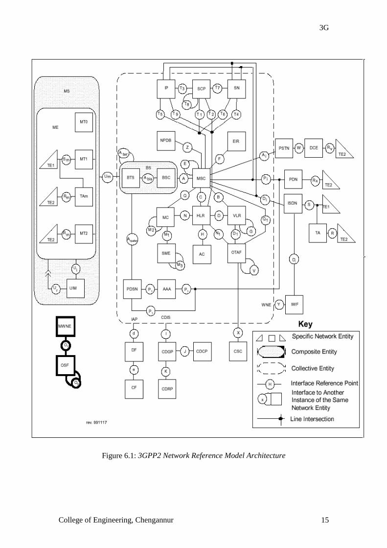
6) 3G NETWORK ARCHITECTURE
The 3G network architecture is very complex and is difficult to
understand & represent. So network reference model is used which makes its
representation simpler.
NETWORK REFERENCE MODEL (cdma2000/3gpp2)
Reference models are graphical tools used to visualize, structure, and
describe certain complex subjects. A few such models are widely used in the 3GPP2
wireless recommendations. Figure 6.1 presents the network entities and associated
reference points that comprise a wireless network. The network entities are
represented by squares, triangles and rounded corner rectangles; the reference points
are represented by circles.
The network reference model is a functional block diagram. A network
entity represents a group of functions, not a physical device. Sometimes, for practical
reasons, the functional network entity is a physical device. The Mobile Station (MS)
is an excellent example.
A reference point is a conceptual point that divides two groups of
functions. It is not necessarily a physical interface. A reference point only becomes a
physical interface when the network entities on either side of it are contained in
different physical devices.
3G
College of Engineering, Chengannur 15
Figure 6.1: 3GPP2 Network Reference Model Architecture

3G
College of Engineering, Chengannur 16
The different components of the network are listed below:
AAA Authentication, Authorization, and Accounting
AC Authentication Center
BS Base Station
BSC Base Station Controller
BTS Base Transceiver System
CDCP Call Data Collection Point
CDGP Call Data Generation Point
CDIS Call Data Information Source
CDRP Call Data Rating Point
CF Collection Function
CSC Customer Service Center
DCE Data Circuit Equipment
DF Delivery Function
EIR Equipment Identity Register
HLR Home Location Register
IAP Intercept Access Point
IP Intelligent Peripheral
ISDN Integrated Services Digital Network
IWF Interworking Function
MC Message Center
MS Mobile Station
MSC Mobile Switching Center
MT Mobile Terminal
MWNE Managed Wireless Network Entity
NPDB Number Portability Database
OSF Operations System Function
OTAF Over-The-Air Service Provisioning Function
PDN Packet Data Network
PDSN Packet Data Serving Node
PSTN Public Switched Telephone Network
SCP Service Control Point
SME Short Message Entity
SN Service Node

3G
College of Engineering, Chengannur 17
TA Terminal Adapter
TE Terminal Equipment
UIM User Identity Module
VLR Visitor Location Register
WNE Wireless Network Entity
Authentication, Authorization and Accounting: The AAA is an entity that provides
Internet Protocol functionality to support the functions of Authentication,
Authorization, and Accounting. These IP functions are defined in Internet
Engineering Task Force documents. The AAA interacts with the PDSN to perform
AAA functions in support of the PDSN for requesting Mobile Stations. The AAA
interacts with other AAA entities to perform AAA functions where the Home AAA is
outside the serving mobile network.
Authentication Center (AC): The AC is an entity that manages the authentication
information related to the MS. The AC may, or may not be located within, and be
indistinguishable from an HLR. An AC may serve more than one HLR.
Base Station (BS): A BS is an entity that provides the means for MSs to access
network services using radio.
It includes a BSC and a BTS.
Base Station Controller (BSC): The BSC is an entity that provides control and
management for one or more BTSs. The BSC exchanges messages with both the BTS
and the MSC. Traffic and signaling concerned with call control, mobility
management, and MS management may pass transparently through the BSC.
Base Transceiver System (BTS): The BTS is an entity that provides transmission
capabilities across the U m reference
point. The BTS consists of radio devices, antenna and equipment.
Call Data Collection Point (CDCP): The CDCP is the entity that collects the IS-124
format call detail information.
Call Data Generation Point (CDGP): The CDGP is an entity which provides call
detail information to the CDCP in IS-124 format. This may be the entity which
converts call detail information from a proprietary format into the IS-124 format. All
information from the CDGP to the CDCP must be in IS-124 format.

3G
College of Engineering, Chengannur 18
Call Data Information Source (CDIS): The CDIS is an entity that can be the source
of call detail information. This information may be in proprietary format. It is not
required to be in IS-124 format.
Call Data Rating Point (CDRP): The CDRP is the entity that takes the unrated IS-
124 format call detail information and
applies the applicable charge and tax related information. The charge and tax
information is added using IS-124 format.
Collection Function (CF) - [Intercept]: The CF is an entity that is responsible for
collecting intercepted communications for a lawfully authorized law enforcement
agency.
The CFs typically include:
• the ability to receive and process call contents information for each intercept
subject.
• the ability to receive information regarding each intercept subject (e.g., call
associated or non-call associated) from the Delivery function and process it.
Customer Service Center (CSC): The CSC is an entity where service provider
representatives receive telephone calls from customers wishing to subscribe to initial
wireless service or request a change in the customer’s existing service. The CSC
interfaces proprietarily with the OTAF to perform network and MS related changes
necessary to complete the service provisioning request.
Data Circuit Equipment (DCE): A termination that provides a non-ISDN user-
network interface (e.g., ITU-T [CCITT] V series, ITU-T [CCITT] X series).
Delivery Function (DF) - [Intercept]: The DF is an entity that is responsible for
delivering intercepted communications to one or more collection functions.
The DFs typically include:
• the ability to accept call contents for each intercept subject over one or more
channels from each Access function.
• the ability to deliver call contents for each intercept subject over one or more
channels to a Collection function as authorized for each law enforcement
agency.
• the ability to accept information over one or more data channels and combine
that information into a single data flow for each intercept subject.

3G
College of Engineering, Chengannur 19
• the ability to filter or select information on an intercept subject before delivery
to a Collection function as authorized for a particular law enforcement agency.
• the optional ability to detect audio in-band DTMF digits for translation and
delivery to a Collection function as authorized for a particular law
enforcement agency.
• the ability to duplicate and deliver information on the intercept subject to one
or more Collection functions as authorized for each law enforcement agency.
• the ability to provide security to restrict access.
Equipment Identity Register (EIR): The EIR is an entity that is the register to
which user equipment identity may be assigned for record purposes. The nature,
purpose, and utilization of this information is an area for further study.
Home Location Register (HLR): The HLR is the location register to which a user
identity is assigned for record purposes such as subscriber information (e.g. Electronic
Serial Number (ESN), Mobile Directory Number (MDN), Profile Information,
Current Location, Authorization Period).
Integrated Services Digital Network (ISDN): The ISDN is defined in accordance
with the appropriate ANSI T1 Standards.
Intelligent Peripheral (IP): The IP is an entity that performs specialized resource
functions such as playing announcements, collecting digits, performing speech-to-text
or text-to-speech conversion, recording and storing voice messages, facsimile
services, data services, etc.
Intercept Access Point (IAP): The IAP is an entity that provides access to the
communications to, or from, the equipment, facilities, or services of an intercept
subject.
Interworking Function (IWF): The IWF is an entity that provides information
conversion for one or more WNEs. An IWF may have an interface to a single WNE
providing conversion services. An IWF may augment an identified interface between
two WNEs, providing conversion services to both WNEs.
Managed Wireless Network Entity (MWNE): A wireless Entity within the
Collective Entity or any specific Network Entity having OS wireless management
needs, including another OS.

3G
College of Engineering, Chengannur 20
Message Center (MC): The MC is an entity that stores and forwards short messages.
The MC may also provide supplementary services for Short Message Service (SMS).
Mobile Station (MS): A wireless terminal used by subscribers to access network
services over a radio interface. MSs include portable units (e.g., hand-held units),
units installed in vehicles, and somewhat paradoxically, fixed location MSs. The MS
is the interface equipment used to terminate the radio path at the subscriber.
Mobile Switching Center (MSC): The MSC switches MS originated or MS
terminated traffic. An MSC is usually connected to at least one BS. It may connect to
the other public networks (PSTN, ISDN, etc.), other MSCs in the same network, or
MSCs in different networks. The MSC may store information to support these
capabilities.
Mobile Terminal 0 (MT0): A self-contained data capable MS termination that does
not support an external interface.
Mobile Terminal 1 (MT1): A MS termination that provides an ISDN user-network
interface.
Mobile Terminal 2 (MT2): A MS termination that provides a non-ISDN user-
network interface (e.g., ITU-T [CCITT] V series, ITU-T [CCITT] X series).
Number Portability Database (NPDB): The NPDB is an entity which provides
portability information for portable Directory Numbers.
Operations Systems Function (OSF): The OSF is defined by the
Telecommunications Management Network (TMN) OSF. These functions include
Element Management Layer (EML), Network Management Layer (NML), Service
Management Layer (SML), and Business Management Layer (BML) functions
spanning across all operations systems functions (e.g., Fault Management,
Performance Management, Configuration management, accounting management and
Security Management.
Over-The-Air Service Provisioning Function (OTAF): The OTAF is an entity that
interfaces proprietarily to CSCs to support service provisioning activities. The OTAF
interfaces with the MSC to send MS orders necessary to complete service
provisioning requests.
Packet Data Serving Node (PDSN): The PDSN is an entity that provides Internet
Protocol functionality to the mobile network. A PDSN establishes, maintains and
terminates link layer sessions to the Mobile Station. A PDSN routes IP datagrams to
the PDN. A PDSN may act as a Mobile IP Foreign Agent in the mobile network. A

3G
College of Engineering, Chengannur 21
PDSN may have interface to one or more Base Stations to provide the link layer
session. A PDSN interacts with the AAA to provide IP authentication, authorization,
and accounting support. A PDSN may interface to one or more IP networks either
public or Intranet to provide IP network access.
Packet Data Network (PDN): A PDN, such as the Internet, provides a packet data
transport mechanism between processing network entities capable of using such
services.
Public Switched Telephone Network (PSTN): The PSTN is defined in accordance
with the appropriate ANSI T1 Standards.
Service Control Point (SCP): The SCP is an entity that acts as a real-time database
and transaction processing system that provides service control and service data
functionality.
Service Node (SN): The SN is an entity that provides service control, service data,
specialized resources and call control functions to support bearer-related services.
Short Message Entity (SME): The SME is an entity that composes and decomposes
short messages. A SME may, or may not be located within, and be indistinguishable
from, an HLR, MC, VLR, MS, or MSC.
Terminal Adapter (TA): An entity that converts signaling and user data between a
non-ISDN and an ISDN interface.
Terminal Adapter m (TAm): An entity that converts signaling and user data
between a non-ISDN and an ISDN interface.
Terminal Equipment 1 (TE1): A data terminal that provides an ISDN user-network
interface.
Terminal Equipment 2 (TE2): A data terminal that provides a non-ISDN user-
network interface (e.g., ITU-T [CCITT] Vseries, ITU-T [CCITT] X series).
User Identity Module (UIM): The UIM contains subscription information such as
the NAM and may contain subscription feature information. The UIM can be
integrated into any mobile terminal or it may be removable.
Visitor Location Register (VLR): The VLR is the location register other than the
HLR used by an MSC to retrieve information for handling of calls to or from a
visiting subscriber. The VLR may, or may not be located within, and be
indistinguishable from an MSC. The VLR may serve more than one MSC.
Wireless Network Entity (WNE): A Network Entity in the wireless Collective
Entity

3G
College of Engineering, Chengannur 22
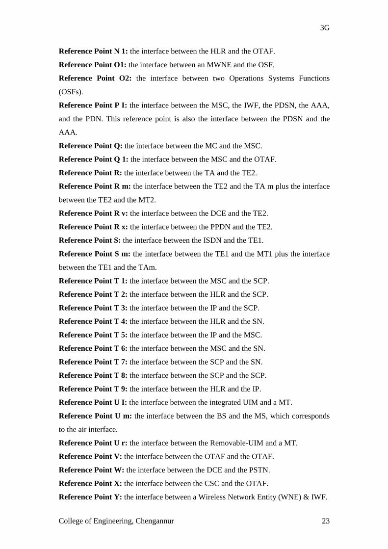
Reference Points
The U m reference point is the only reference point that is by definition a
physical interface. The other reference points will be physical interfaces if network entities on
either side them are contained in different physical devices. An interface exists when two
Network Entities are interconnected through exactly one Reference Point.
Reference Point A: the interface between the BSC and the MSC.
Reference Point A I: the interface between the IP and the PSTN, plus the interface
between the MSC and the PSTN, plus the interface between the SN and the PSTN.
Reference Point A bis: the interface between the BSC and the BTS.
Reference Point A ter: is the BS to BS interface.
Reference Point Aquater: the interface between the PDSN and the BS.
Reference Point B: the interface between the MSC and the VLR.
Reference Point C: the interface between the MSC and the HLR.
Reference Point D: the interface between the VLR and the HLR.
Reference Point d: the interface between an IAP and the DF.
Reference Point D 1: the interface between the OTAF and the VLR.
Reference Point D I: the interface between the IP & the ISDN, the IWF & the ISDN,
the interface between the MSC & the ISDN & the interface between the SN & ISDN.
Reference Point E: the interface between the MSC and the MSC.
Reference Point e: the interface between the CF and the DF.
Reference Point F: the interface between the MSC and the EIR.
Reference Point G: the interface between the VLR and the VLR.
Reference Point H the interface between the HLR and the AC.
Reference Point I: the interface between the CDIS and the CDGP. The operations
supported by this interface are described in IS-124.
Reference Point J: the interface between the CDGP and the CDCP. The operations
supported by this interface are described in IS-124.
Reference Point K: the interface between the CDGP and the CDRP. The operations
supported by this interface are described in IS-124.
Reference Point L: Reserved.
Reference Point M 1: the interface between the SME and the MC.
Reference Point M 2 the MC to MC interface.
Reference Point M 3: the SME to SME interface.
Reference Point N: the interface between the HLR and the MC.
3G
College of Engineering, Chengannur 23
Reference Point N 1: the interface between the HLR and the OTAF.
Reference Point O1: the interface between an MWNE and the OSF.
Reference Point O2: the interface between two Operations Systems Functions
(OSFs).
Reference Point P I: the interface between the MSC, the IWF, the PDSN, the AAA,
and the PDN. This reference point is also the interface between the PDSN and the
AAA.
Reference Point Q: the interface between the MC and the MSC.
Reference Point Q 1: the interface between the MSC and the OTAF.
Reference Point R: the interface between the TA and the TE2.
Reference Point R m: the interface between the TE2 and the TA m plus the interface
between the TE2 and the MT2.
Reference Point R v: the interface between the DCE and the TE2.
Reference Point R x: the interface between the PPDN and the TE2.
Reference Point S: the interface between the ISDN and the TE1.
Reference Point S m: the interface between the TE1 and the MT1 plus the interface
between the TE1 and the TAm.
Reference Point T 1: the interface between the MSC and the SCP.
Reference Point T 2: the interface between the HLR and the SCP.
Reference Point T 3: the interface between the IP and the SCP.
Reference Point T 4: the interface between the HLR and the SN.
Reference Point T 5: the interface between the IP and the MSC.
Reference Point T 6: the interface between the MSC and the SN.
Reference Point T 7: the interface between the SCP and the SN.
Reference Point T 8: the interface between the SCP and the SCP.
Reference Point T 9: the interface between the HLR and the IP.
Reference Point U I: the interface between the integrated UIM and a MT.
Reference Point U m: the interface between the BS and the MS, which corresponds
to the air interface.
Reference Point U r: the interface between the Removable-UIM and a MT.
Reference Point V: the interface between the OTAF and the OTAF.
Reference Point W: the interface between the DCE and the PSTN.
Reference Point X: the interface between the CSC and the OTAF.
Reference Point Y: the interface between a Wireless Network Entity (WNE) & IWF.

3G
College of Engineering, Chengannur 24
Reference Point Z: the interface between the MSC and the NPDB.
Figure 6.2: A simplified block diagram of a 3G system

3G
College of Engineering, Chengannur 25
7) 3G DUPLEX TECHNIQUES
3G standards employing WCDMA uses two types of duplexing techniques:
Time Division Duplex (TDD) and Frequency Division Duplex (FDD).
Frequency Division Duplex
The frame structure in the FDD component is different in the uplink
and downlink. In the uplink, the data and control channels are I/Q multiplexed,
whereas in the downlink data and control channels are time multiplexed. The FDD
component applies two-layered consisting of spreading codes and scrambling (long)
codes. The I/Q multiplexed DPDCH and DPCCH in the uplink are quadrature phase
shift keying (QPSK) modulated. Each channel is scrambled with a specific code for
DPDCH and for DPCCH, and then scrambled with a mobile station specific
scrambling code to distinguish different mobile stations. Each DPDCH is assigned its
own channelization code.
On the downlink multiple codes are transmitted with possibly different
spreading factors for the different DPCHs depending on the service. The data
modulation is QPSK. Spreading is performed by channelization codes for each DPCH
and a cell specific scrambling code to distinguish different cells. In the downlink the
scrambling code is a cell specific 10ms (40960 chips) segment of a Gold code
sequence. The FDD component supports both synchronous and asynchronous inter
cell operation.
Time Division Duplex
The TDD component is based on TD-CDMA, which is a combination
of TDMA and CDMA. Each time slot comprises several (maximum 16) orthogonal
spreading codes. Different user rates are supported by code and/or time slot pooling.
In the uplink the variable orthogonal spreading rate is also applied.
Due to the same carrier frequency in the uplink and downlink, a TDD
system requires a frame synchronized network to control interference for coordinated
operation.

3G
College of Engineering, Chengannur 26
8) WCDMA CHANNEL STRUTURE
The WCDMA channels can be classified as follows. A logical channel is
defined by the type of information transferred. The logical channel types are:
! Control Channels (CCH) with logical broadcast control channel (L-
BCCH), logical forward access channel (L-FACH), logical random
access channel(L-RACH), and dedicated control channel(DCCH)
! Traffic channels (TCH) with dedicated traffic channel (DTCH) and
user packet traffic channel (UPCH)
The physical layer offers information transfer services to the medium
access control (MAC) and higher layers. The physical layer transport services are
described by how and with what characteristics data are transferred over the radio
interface. An adequate term for this is the transport channel. Transport channels can
be generally classified into two types:
! Common channels with broadcast control channel (BCCH), paging
channel (PCH), forward access channel (FACH), and random access
channel (RACH)
! Dedicated channels (DCH)

3G
College of Engineering, Chengannur 27
Figure 8.1: CDMA channel structure

3G
College of Engineering, Chengannur 28
9) 3G PROTOCOLS
The protocol stack proposed for 3g wireless platform is shown below:
WAPTCPIP
IP over WmATMWmATM with WAAL
MACDBA
Physical Layer
WmATM cells are generated through the wireless ATM adaptation
layer (WAAL). The DBA (Dynamic Bandwidth allocation) layer handles dynamic
bandwidth allocation to increase the spectrum utilization. The wireless application
protocol (WAP) is the de facto world standard for the presentation and delivery of
wireless information. As per the International telecommunication union- radio
communication standard sector (ITU-R) IOMT-2000 radio transmission technology
adopts the CDMA and TDMA for the physical layer, which contain 16 time division
duplex time slots and each slot can be composed of up to 64 CDMA codes for the 3g
wireless systems.
Different services have various quality of service requirements as well
as system parameters, so the bandwidth allocation should be dynamic and adaptive.
This kind of MAC (Media access controller) can be implemented using DSP. 3G also
supports Internet access through the mobile terminal, therefore it has to support
TCP/IP protocols.

3G
College of Engineering, Chengannur 29
10) 3G HANDSET
The common trends in 3G terminals are:
! Bigger and better screen technology- screens will be color and must have
considerably larger screen areas.
! Video and multimedia are central to the technology demonstration. So
videoconference is an application that many of the concept terminals anticipate.
! Majority of 3G terminals include a miniature camera built into it.
10.1) HARDWARE REQUIREMENTS
Third generation handsets will demand new levels of performance
from their RF sections. To meet the wider bandwidth, increased linearity and lower
power requirements lead to high speed, low noise, bipolar integration technologies
such as GaAs. One of the main challenges will be in the mixed signal area such as
analog to digital converters and digital to analog converters that will have to operate
at 10 mega samples per second. 3G products will be able to reduce the number and
size of external passive devices used for filtering and coupling. Another difficulty is
accommodating variable carrier bandwidth. So we move digitization of signals much
closer to antenna enabling designers to use programmable DSPs to perform
demodulation and decoding. It takes around 60 MIPS worth of DSP to support a
typical GSM phone whereas a 3G EWCDMA phone will require 300 MIPS.
Figure 10.1: An implementational framework of a 3G (tri-mode) phone with support
for global roaming
Real Time Operating System
SmartAntenna
Array
DigitalBroadbandTransceiver
Baseband
Processing
Unit
WCDMA Module
EDGE Module
cdma2000 Module

3G
College of Engineering, Chengannur 30
Users, operators & vendors want to improve the flexibility & capability
of their wireless communication equipments by using software reconfigurable radio
technology offers a potential of substantially improved operational capability at a
lower cost. It also offers multi mode operations using the same hardware by simply
changing the embedded software. This supports multi mode global roaming phones at
an affordable price.
The main functional blocks in a 3G handset are the following :
1. A Smart Antenna Array: This antenna array is capable of controlling
transmitted power according to the control information from the BTS. Most
3G systems employ a closed loop power control
2. Front End High Speed ADC & DAC: The third generation terminals make
use of high speed ADC and DAC in the RF stage. This helps to use
programmable DSP circuitry for up and down conversions, modulation-
demodulation and coding-decoding functions.
3. A Microcontroller: This microcontroller controls the DSP operations and also
helps in power management. In most of the 3G phone chipsets the
microcontroller and the DSP are integrated into a single chip.
4. Colour LCD Display: As 3G system supports multimedia applications and
mobile teleconferencing, a comparatively larger multi colour LCD display is
necessary.
5. Signal Processing Circuitry: This will be a DSP processor which will handle
digital audio decoding, video streaming, voice compression, channel coding,
modem, equalization, encryption, echo cancellation, speech recognition, noise
suppression security encryption and decryption, for mobile commerce and
more to add new functionality to digital wireless phones (The world's lowest
power DSP, the new TMS320C55x™ announced February 22, 2000, is the
processor of choice for the next-generation digital wireless phones and a
whole new generation of wireless Internet appliances)
10.2) SOFTWARE REQUIREMENTS
As the 3G phones use programmable hardware an
embedded operating system is used in addition to this to handle user interface of the
phone a Java Virtual Machine is used.

3G
College of Engineering, Chengannur 31
11) 3G-QUALITY OF SERVICE
First and second-generation cellular systems provided their circuit
switched resources to subscribers with a fixed quality of services (QoS). Networks in
the latest generation, on the other hand, will assign default QoS profiles to users and
their applications. A subscriber’s application negotiates a suitable QoS profile with
the network which allots its resources according to the default profile or with some
alternative profile, depending on the load on the network, the propagation conditions
and QoS profiles authorized by user’s subscription.
At the subscriber level, four kinds of traffic can be distinguished:
conversational, streaming, interactive and background.
Conversational traffic is the most familiar type of traffic. Fairly
tolerant of errors, conversational and videoconferencing traffic have different
throughput requirements, but they demand a constant and rather short end-to-end
delay.
Streaming traffic applies to applications that can start processing the
traffic for presentation to the user before the whole file is transmitted to the
subscriber. It can work within a small range of delays and throughput delays.
Interactive traffic is used by online applications, in which a subscriber
is allowed to interact with a server of some kind: Web browsing, e-commerce, games
and location-based services. Interactive traffic can work acceptably over an
intermediate range of delays and throughput rates.
Finally, background traffic is very tolerant of delays, works within a
wide range of throughput rates, but is relatively intolerant of errors. These include
applications such as e-mail, short messaging services and file downloads. Background
traffic is the most naturally compatible with packet data networks.

3G
College of Engineering, Chengannur 32
12) 3G APPLICATIONS
There are several applications that will be enabled by the broadband
wireless communication channels that will come with 3G. These applications include:
AUDIO
Audio or video over the Internet is downloaded (transferred, stored
and played) or streamed (played as it is being send but not stored). The different
compression algorithms such as MP3 can be used. With 3G, MP3 files will be
downloadable over the air directly to the phone via a dedicated server. The large
computational power available in the 3G phones helps the decoding of MP3 formats.
VOICE OVER INTERNET PROTOCOL
Another audio application for 3G is Voice over IP (VoIP) – the ability
to route telephone calls over the Internet to provide voice telephone service at local
call rates to anywhere in the world. With the higher data rates supported by 3G, VoIP
will be available on mobile phones.
STILL IMAGES
Still images such as photographs, pictures, letters, postcards, greeting
cards, presentations and static web pages can be send and received over mobile
networks just as they are across an IP based network.
MOVING IMAGES
Sending moving images in a mobile environment has several vertical
market applications including monitoring parking lots or building sites for intruders or
thieves, sending images of a patient from an ambulance to a hospital, mobile video
conferencing applications etc.
VIRTUAL HOME ENVIRONMENT (VHE)
A Universal Mobile Telecommunications Services (UMTS) service
that is often mentioned in the vendor’s brochures is so called Virtual Home
Environment, a service that simply lets customers have seamless access with a
common look and feel to their services from home, office or on the move in any city

3G
College of Engineering, Chengannur 33
as if they were at home. VHE is there fore aimed at roamers, a small subset of mobile
phone users. VHE could also allow some other useful services by placing their
Universal Identity Module into any terminal and those terminals could be other than
mobile devices (if smart cards are more widely supported than they are today).
ELECTRONIC AGENTS
Electronic agents are supposed to play an important role for mobile
working in the future – as agents are dispatched to carry out searches and tasks on the
Internet and report back to their owners. This is an efficient way to get things done on
the move. Electronic agents are defined as “ mobile programs that go to places in the
network to carry out their owner’s instructions”. Agents are self-contained programs
that roam communication networks, delivering and receiving messages or looking for
information or services. Certainly, 3G terminals will give their owners much more
control over their lives than today’s mobile phones. They will be e-assistance, e-
secretaries, e-advisors, e-administrators etc. This kind of control is what home
automation applications anticipate.
DOWNLOADING SOFTWARE
In the 21st century, software will increasingly be downloaded
electronically from the Internet rather than purchased as boxed products in stores.
This is like file transfer applications that involve downloading the software itself. We
might, for example need WinZip or adobe acrobat to read a file and can download that
over the 3G network to a 3G terminal. Additionally Application Service Provision
(ASP) market in which software platforms and server software is being hosted by
third parties and accessed by client software mimics this thin client world in which the
bandwidth is high enough for applications and files to be retrieved from the Internet
on the fly whenever they are needed.

3G
College of Engineering, Chengannur 34
Figure 12.1: Different 3G applications and corresponding data rates
Figure 12.2: User Applications

3G
College of Engineering, Chengannur 35
13) 3G DRAWBACKS
The main draw back of 3G is its high cost. Considering a typical
example, to set up 3G trial network infrastructure The Nippon Telephone and
Telegraph had to invest 18$ billion in 1999. Also a 3G phone may cost 1000$+.
The second disadvantage is shorter battery life of 3G phones when
compared to 2G mobile phones. This is because 3G phones have a comparatively
larger display screen and the increased power consumption of modern high speed
DSP processors used in 3G phones.
The most important disadvantage of 3G services is the lack of an
internationally uniformed standard. The third generation cellular telephony is on its
way, not as a single worldwide system but as three incompatible ones. This will make
the global roaming difficult. For global roaming we have to use multimode phones,
which can operate in different radio interface standards and this will result in costlier
handsets.

3G
College of Engineering, Chengannur 36
14) VISIONS OF THE FUTURE
3G is capable of providing very high data rate in different radio
environments. It can provide dream multimedia services. At present there is no hope
of a wireless communication technology, which can perform better than 3G. It is
expected that the trends should last into a Fourth Generation (4G) of even better
spectrum efficiencies, higher radio carrier frequencies, even higher user data rates,
and a blizzard of new non voice applications plus the terminals to support them.
A wireless terminal that is your gateway to the world of voice data,
video and multimedia communications sounds possible sooner. The year is 2005, your
traveling in the passenger seat of your work-colleague’s car with a laptop computer in
front of you, you sip a cup of coffee while you write a short report on the meeting you
attended that day. Suddenly, you hear the tone that tells you there’s an incoming
videoconference call. You click on the screen icon, the computer screen changes and
you see your assistant’s face. The two of you have a brief conversation. Then she tells
you about a new intranet site that could b useful for your next customer meeting. So
without interrupting the conversation, you take a look at the website, and your
assistant guides you to the most interesting pages. A few minutes later, your sales
department calls and sends you the technical specifications and pricing information
that you need for your next meeting. At the same time you send your completed report
to the eight people who need copies. Meanwhile, a memo from one of your co-
directors arrives on your computer. It’s about an important item on your own
company, broadcast on that morning’s TV news report. A clip of the TV item is
attached to the e-mail, so you watch it. This is not science fiction, it a preview of
everyday communication services that will be a commercial reality within the next
few years. So called “third generation” wireless services (also referred to as “3G
services”) will significantly expand the range of options available to users and allow
communications, information and entertainment services to be delivered via wireless
terminals. The exciting thing is that the foundation for these services has already been
laid down – in a shape of today’s digital mobile phone networks. All that is needed to
support these advanced multimedia services is to expand the information capacity, or
“bandwidth” of the radio communications technology.

3G
College of Engineering, Chengannur 37
15) CONCLUSION
A tremendous growth of mobile subscribers is expected, with nearly
1.8 billion in the year 2010 with a dominant base in Asia. GSM is the mobile radio
standard with the highest penetration world wide. Mobile multimedia will increase
after the year 2000 to about 60% of the traffic in the year 2010. Therefore third
generation systems have to support a wide range of services from voice to low data
rate up to high data rate circuit switched and packet oriented services. In addition a
high grade of asymmetry for data application is expected. With this wireless break
through, unified IP network including wireless and wireline provides a generic
information transmission platform for value added personal Internet services and
multidimensional wireless communication services.
In this seminar we briefly surveyed the evolution 3G wireless
systems from 2G and 2.5G technologies. Similarities and key differences between the
various 3G proposals submitted to ITU-R are reviewed. IN order to have a common
standard for RTT, it is imperative to carry out harmonization in an international level.
With the recent technological breakthroughs in digital signal processing, RF and
battery technologies as well as developments in modern VLSI chip designs, the dream
of ubiquitous communication between any one, any where, at any time is becoming a
reality. To cut it short, we can say that the wireless information super highway is
converging to 3G and during the coming decade we will see how 3G will make the
other wireless communication methods obsolete.