ba7500man
TRANSCRIPT

Digital BA7500TM
5.1 Dolby® Digital Surround Speaker System
Slimline Speaker TechnologyTM (SSTTM)
4-Channel Sound Card Compatibility

This Package Contains:1 Amplified subwoofer2 Front SST satellite speakers with captive cords2 Rear SST satellite speakers with 20' captive cords3 Satellite speaker desktop stands1 Audio controls pod/stand with captive DIN cable1 Digital input RCA cable1 Unified stereo analog cable for front and rear input1 8" “Y” adapter cord for rear speaker output4 Self-adhesive rubber feet for subwoofer1 Pack of self-adhesive rubber feet for satellites1 Transformer with power cord1 RCA-to-phono adapter2 Rear surround tower stands
DescriptionQuality theater audio for the desktop has arrived. Using an internal Dolby® Digital surround processor, theDigital BA7500 delivers 5.1 movie audio from your PC’s DVD-ROM without the need for a separatereceiver or decoder. Four Boston SST™ (Slimline Speaker Technology™) satellites, an amplifiedsubwoofer and the processor’s “virtualized” center create six distinct cinema sound fields. With a 4-channel sound card, it brings multi-channel PC gaming to a new level of realism. As a stereo musicsystem, the BA7500 has maintained the highest level of fidelity, equal in performance to some shelfmonitors.
Building on Boston’s proven 6½" bandpass subwoofer, the technological highlight of the Digital BA7500 isthe four SST satellites. Boston sets the standard: The technology found in the SST’s allows us to deliverthe same high-fidelity audio found in Boston’s larger home theater products and still maintain a sleek,attractive profile. Front pedestal stands, rear tower stands, a desktop audio control pod and extra-longsurround cables make for easy 3D positioning and operation. Desktop controls include Master Volume,Surround Volume, Surround Balance and Subwoofer Level. Each satellite is protected by magneticshielding to prevent video interference.
SpecificationsFREQUENCY RESPONSE (±3dB) 45Hz - 20,000Hz
MAXIMUM SOUND PRESSURE LEVEL (0.7m) 107dB
SUBWOOFER 61/2" (165mm)
SATELLITES SSTTM Panels
CROSSOVER FREQUENCY 170Hz
DIMENSIONS (HxWxD) Subwoofer 113/4 x 7 x 145/8" (299 x 178 x 372mm)
Satellites (h x w x d / without stand) 911/16 x 41/16 x 11/8" (246 x 103 x 29mm)
WEIGHT Subwoofer11.1 lbs. (5.0 kg)Satellites0.8 lbs. (0.4 kg) each (without stand)
FINISH Computer Gray & Charcoal Screen
Additional Features:Manual on/off control (Turn “Volume” control far left)
Optional Virtualized Dolby Surround effect when usedas a 3-piece system
Variable desktop audio controls (Master Volume, Surround Volume, Surround Balance & Subwoofer Levels)
Long rear speaker cords and tower stands foraccurate positioning
Dolby® Digital (AC-3) processing built in and/or 4-channel sound card compatibility
Keyhole hooks on all satellites for wall mounting
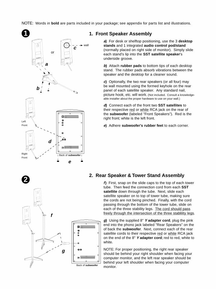
1. Front Speaker Assemblya) For desk or shelftop positioning, use the 3 desktopstands and 1 integrated audio control pod/stand(normally placed on right side of monitor). Simply slideeach stand's lip into the SST satellite speaker 'sunderside groove.
b) Attach rubber pads to bottom tips of each desktopstand. The rubber pads absorb vibrations between thespeaker and the desktop for a cleaner sound.
c) Optionally, the two rear speakers (or all four) maybe wall mounted using the formed keyhole on the rearpanel of each satellite speaker. Any standard nail,picture hook, etc. will work. (Not included. Consult a knowledge-able installer about the proper hardware to use on your wall.)
d) Connect each of the front two SST satellites totheir respective red or white RCA jack on the rear ofthe subwoofer (labeled "Front Speakers"). Red is theright front; white is the left front.
e) Adhere subwoofer's rubber feet to each corner.
2. Rear Speaker & Tower Stand Assemblyf ) First, snap on the slide caps to the top of each towertube. Then feed the connection cord from each SSTsatellite down through the tube. Next, slide eachsatellite speaker on to top of tower tube, making surethe cords are not being pinched. Finally, with the cordpassing through the bottom of the tower tube, slide oneach of the three stability legs. The cord should passfreely through the intersection of the three stablility legs.
g) Using the supplied 8" Y adapter cord , plug the pinkend into the phono jack labeled "Rear Speakers" on theof back the subwoofer . Next, connect each of the rearsatellite cords to their respective red or white RCA jackon the end of the 8" Y adapter cord ; red to red, white towhite.
NOTE: For proper positioning, the right rear speakershould be behind your right shoulder when facing yourcomputer monitor, and the left rear speaker should bebehind your left shoulder when facing your computermonitor.
1
NOTE: Words in bold are parts included in your package; see appendix for parts list and illustrations.
or
wall
a
c
b
Back of subwoofer
2
f
g
d
Left
Front
Right
FrontBack of subwoofer
e

or
i2) My sound card has 2 STEREO LINE OUTPUTS(4-channel): For sound cards with a 4-channelgaming configuration, use your unified stereo cable(see part illustration in appendix). Connect the greenand purple end of the unified stereo cable to thegreen and purple inputs at the subwoofer (these arelabeled "Front" and "Rear" respectively on the back ofthe subwoofer ). On the opposite end of the unifiedstereo cable , connect the green plug to the soundcard's front output (normally labeled "1", "front" orgreen), and the black plug to the sound card's rearoutput (normally labeled "2", "rear" or black). You willnot need your digital RCA cable for this setup.
ori3) My sound card has 2 STEREO LINE OUTS anda DIGITAL (S/PDIF) OUT: For sound cards with 2stereo outputs and an added digital output on thesame card, use the unified stereo cable supplied(see part illustration in appendix) and connect thepurple end of the unified stereo cable to thesubwoofer 's "Rear Analog Input". Connect theopposite black end of the unified stereo cable to thesound card's rear output (normally labeled "2", "rear"or black). You will not need to use either of the greenends with this setup. Next, using your digital RCAcable (see part illustration in appendix), connect oneof the black ends to the subwoofer 's "Digital Input".The opposite end of this digital RCA cable shouldplug into your sound card's digital S/PDIF output.NOTE: It may be necessary to use the RCA-to-phono adapter (see part illustration in appendix) ifyour card's digital output is a phono jack instead of acoaxial.
h) Connect the system's control pod cable(blue) to the "Control" jack (also blue) on theback of the subwoofer .
STOP: For step 'i' you will needto carefully identify which type ofsound card setup you have: i1,i2, i3 or i4.
i1) My sound card has 1 ANALOG OUT-PUT: Using your unified stereo cable (seepart illustration in appendix), plug the greenend into the subwoofer 's "Front Analog Input",and the opposite green end into the soundcard's single audio output. You will not needthe digital RCA cable or the purple and blackends of the unified cable for this setup.SPECIAL FEATURE: When operating as a3-piece (or front channel input only), thesystem has the ability to create a VirtualizedDolby Surround effect; use Surround Vol.
3. Input Panel Connections3
(Sound card sample illustration)
Phono jacks RCA (coxial)digital output
i3
Back of computer
i2
Back of computerBack of subwoofer
Back of subwoofer
h
i1
Back of computerBack of subwoofer

4
ori4) My sound card has 2 STEREO OUTPUTS with aSEPARATE DVD DECODER CARD: Using the unifiedstereo cable (see part illustration in appendix below),connect the green and purple end of the unified stereo cableto the green and purple jacks on the back of the subwoofer(these are labeled "Front" and "Rear" respectively on the backof the subwoofer). On the opposite end of the unified stereocable , connect the green plug to the sound card's front output(normally labeled "1", "front" or green), and the black plug tothe sound card's rear output (normally labeled "2", "rear" orblack). Next, using the digital RCA cable (see part illustra-tion in appendix below), connect one of the black ends to the"Digital Input" on the back of the subwoofer . The oppositeend of the digital RCA cable should connect to the DVDdecoder card's digital S/PDIF out. NOTE: It may be neces-sary to use the RCA-to-phono adapter (see part illustrationin appendix below).
j ) Plug in power cable/transformer into back ofsubwoofer and any available AC outlet.
Back of subwoofer
j
i4
Back of computerBack of subwoofer
3 (cont.)
Appendix: Parts included
(1) Unified stereoanalog cable (1) Transformer
with power cord
(1) Amplified andported subwoofer
(1) RCA-to-phonoadapter
(1) 8" Y adapter cordfor rear speakers
(1) Digital RCA cable*
(4) Self-adhesivesubwoofer feet
(4) SST™ satellitespeakers
(1) Pack of self-adhesive rubberfeet for satellites
(1) Audio controlspod/stand
(3) Desktopspeaker stands
(2) Rear towerstands (someassembly required)
* Only use the Digital cable (with a 3.5mm RCA connector) supplied by Boston Acoustics with this product. Do not extend this cable.
*

Limited WarrantyFor one year from the date of purchase, Boston Acoustics will repair for the original owner any defect in materials orworkmanship that occurs in normal use of the speaker system, without charge for parts and labor.
Your responsibilities are to use the system according to the instructions supplied, to provide safe and secure transporta-tion to an authorized Boston Acoustics service representative and to present proof of purchase in the form of your salesslip when requesting service.
Excluded from this warranty is damage that may result from abuse, misuse, accidents, shipping, or repairs or modifica-tions by anyone other than an authorized Boston Acoustics service representative.
This warranty is void if the serial number has been removed or defaced.
This warranty gives you specific legal rights, and you may also have other rights that may vary from state to state.
If Service Seems NecessaryPlease, contact the retailer from whom you purchased the system. If that is not possible, write to:
Boston Acoustics, Inc., 300 Jubilee Drive, Peabody, MA 01960, or call 1-(978)-538-5000.
We will promptly advise you of what action to take. If it is necessary to return your speaker to the factory, please ship itprepaid. After it has been repaired, we will return it freight prepaid in the U.S. and Canada.
© Copyright 1999 Boston Acoustics, Inc. All rights reserved.SST, Slimline Speaker Technology and Digital BA7500 aretrademarks and Boston, and Boston Acoustics are registeredtrademarks of Boston Acoustics, Inc. All other trademarks andregistration marks are the property of their respective owners.Specifications subject to change without notice.
042-001131-0
300 Jubilee DrivePeabody, MA 01960, USA(978) 538-5000www.bostonacoustics.com
Notice of FCC Compliance
This device complies with part 15 of the FCC Rules. Operation is subject to the following two conditions: (1) Thisdevice may not cause harmful interference, and (2) this device must accept any interference received, includinginterference that may cause undesired operation.
Note: This equipment has been tested and found to comply with the limits for a Class B digital device, pursuant to part15 of the FCC Rules. These limits are designed to provide reasonable protection against harmful interference in aresidential installation. This equipment generates, uses and can radiate radio frequency energy and, if not installedand used in accordance with the instructions, may cause harmful interference to radio communications. However,there is no guarantee that interference will not occur in a particular installation. If this equipment does cause harmfulinterference to radio or television reception, which can be determined by turning the equipment off and on, the user isencouraged to try to correct the interference by one or more of the following measures:
-- Reorient or relocate the receiving antenna
-- Increase the separation between the equipment and receiver
-- Connect the equipment into an outlet on a circuit different from that to which the receiver is connected
-- Consult the dealer or an experienced radio/TV technician for help