ba00278ren_0313
DESCRIPTION
ria14 endress hauserTRANSCRIPT
Products Solutions ServicesBA00278R/09/EN/03.1371217666
SW Version:01.00.xx
Operating InstructionsRIA14Field Indicator

Endress+Hauser
Brief operating instructionsFor quick and easy commissioning:
Safety instructions → ä 4
Æ
Installation → ä 7
Æ
Wiring → ä 11
Æ
Display and operating elements → ä 14
Æ
Device configuration → ä 19
Device configuration - Explanation and application of all adjustable device functions with the related ranges of values and settings.
RIA14
Endress+Hauser 3
Table of contents
1 Safety instructions . . . . . . . . . . . . . . . . . . 41.1 Designated use . . . . . . . . . . . . . . . . . . . . . . . . . . . . . 41.2 Installation, commissioning, operation . . . . . . . . 41.3 Operational safety . . . . . . . . . . . . . . . . . . . . . . . . . . . 41.4 Return . . . . . . . . . . . . . . . . . . . . . . . . . . . . . . . . . . . . . 41.5 Notes on safety conventions and icons . . . . . . . . . 5
2 Identification . . . . . . . . . . . . . . . . . . . . . . 62.1 Device designation . . . . . . . . . . . . . . . . . . . . . . . . . . 62.2 Scope of delivery . . . . . . . . . . . . . . . . . . . . . . . . . . . . 62.3 Certificates and approvals . . . . . . . . . . . . . . . . . . . . 6
3 Function and system design. . . . . . . . . . 7
4 Installation . . . . . . . . . . . . . . . . . . . . . . . . 74.1 Incoming acceptance, transport, storage . . . . . . . . 74.2 Installation conditions . . . . . . . . . . . . . . . . . . . . . . . 74.3 Mounting instructions . . . . . . . . . . . . . . . . . . . . . . . 84.4 Post-installation check . . . . . . . . . . . . . . . . . . . . . 10
5 Wiring . . . . . . . . . . . . . . . . . . . . . . . . . . . 115.1 Quick wiring guide . . . . . . . . . . . . . . . . . . . . . . . . 115.2 Electrical connection . . . . . . . . . . . . . . . . . . . . . . . 125.3 Degree of protection . . . . . . . . . . . . . . . . . . . . . . . 135.4 Post-connection check . . . . . . . . . . . . . . . . . . . . . 13
6 Operating the field indicator . . . . . . . . 146.1 Display and operating elements . . . . . . . . . . . . . 146.2 Configuration via operating keys . . . . . . . . . . . . 146.3 Operating matrix . . . . . . . . . . . . . . . . . . . . . . . . . . 166.4 Configuration via interface & FieldCare Device Setup
PC configuration software . . . . . . . . . . . . . . . . . . 17
7 Device configuration . . . . . . . . . . . . . . . 197.1 Data processing (INPUT) . . . . . . . . . . . . . . . . . . . 197.2 Display (DISPL) . . . . . . . . . . . . . . . . . . . . . . . . . . . 207.3 Limit values (LIMIT) . . . . . . . . . . . . . . . . . . . . . . . 217.4 Other settings (PARAM) . . . . . . . . . . . . . . . . . . 227.5 Service level (SERV) . . . . . . . . . . . . . . . . . . . . . . 23
8 Commissioning. . . . . . . . . . . . . . . . . . . . 248.1 Function check . . . . . . . . . . . . . . . . . . . . . . . . . . . 24
9 Maintenance. . . . . . . . . . . . . . . . . . . . . . 25
10 Accessories . . . . . . . . . . . . . . . . . . . . . . . 25
11 Trouble-shooting . . . . . . . . . . . . . . . . . . 2511.1 Trouble-shooting instructions . . . . . . . . . . . . . . . 2511.2 Process error messages . . . . . . . . . . . . . . . . . . . . 25
11.3 Spare parts . . . . . . . . . . . . . . . . . . . . . . . . . . . . . . . . 2611.4 Return . . . . . . . . . . . . . . . . . . . . . . . . . . . . . . . . . . . 2711.5 Disposal . . . . . . . . . . . . . . . . . . . . . . . . . . . . . . . . . . 27
12 Technical data . . . . . . . . . . . . . . . . . . . . 27
Index . . . . . . . . . . . . . . . . . . . . . . . . . . . . 33

Safety instructions RIA14
4 Endress+Hauser
1 Safety instructions
1.1 Designated use‣ The device is a configurable field indicator with one sensor input. ‣ The device is designed for installation in the field.‣ The manufacturer does not accept liability for damage caused by improper or non-
designated use.‣ Safe operation is only guaranteed if the Operating Instructions are observed and adhered
to.‣ Only operate the device in the permitted temperature range.
1.2 Installation, commissioning, operation Note the following points:• Mounting, electrical installation, commissioning and maintenance of the device must only
be carried out by trained technical personnel authorised to perform such work by the owner-operator. They must have read and understood these Operating Instructions and must follow the instructions they contain.
• The device must be operated by persons authorised and trained by the facility's owner-operator. Strict compliance with the instructions in these Operating Instructions is mandatory.
• The installer must ensure that the measuring system is correctly wired in accordance with the wiring diagrams.
• Invariably, local regulations governing the opening and repair of electrical devices apply.
1.3 Operational safetyThe measuring system complies with the general safety requirements in accordance with EN 61010 and the EMC requirements of EN 61326 and NAMUR Recommendations NE 21.
Hazardous area
Measuring systems for use in hazardous environments are accompanied by separate “Ex documentation”, which is an integral part of these Operating Instructions. Strict compliance with the installation instructions and connection values as stated in this supplementary documentation is mandatory.
1.4 ReturnTo reuse later or in case of repair, the device must be packed in protective packaging, preferably the original packaging. Repairs must only be carried out by your supplier's service organisation or specially trained personnel.An overview of the service network is provided on the back page of these Operating Instructions. Enclose a note describing the fault and the application when sending the unit in for repair.
Please inform the haulier and the supplier if the goods are damaged in transport.
RIA14 Safety instructions
Endress+Hauser 5
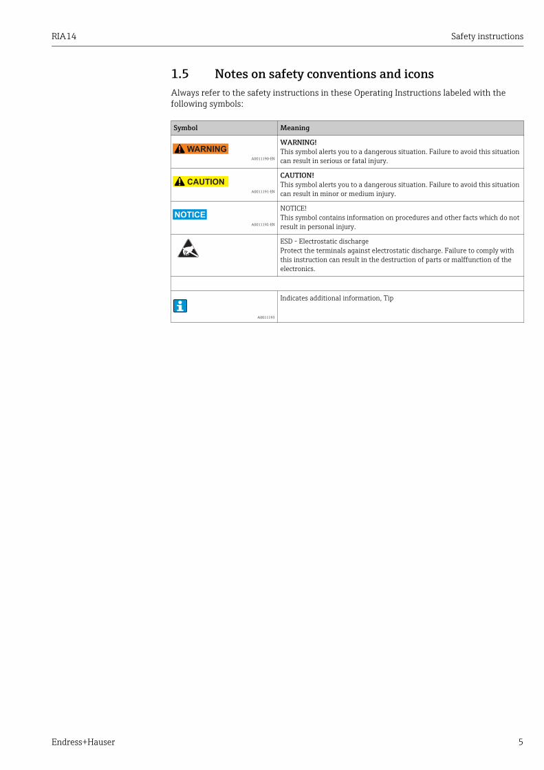
1.5 Notes on safety conventions and iconsAlways refer to the safety instructions in these Operating Instructions labeled with the following symbols:
Symbol Meaning
A0011190-EN
WARNING!This symbol alerts you to a dangerous situation. Failure to avoid this situation can result in serious or fatal injury.
A0011191-EN
CAUTION!This symbol alerts you to a dangerous situation. Failure to avoid this situation can result in minor or medium injury.
A0011192-EN
NOTICE!This symbol contains information on procedures and other facts which do not result in personal injury.
ESD - Electrostatic dischargeProtect the terminals against electrostatic discharge. Failure to comply with this instruction can result in the destruction of parts or malffunction of the electronics.
A0011193
Indicates additional information, Tip
Identification RIA14
6 Endress+Hauser
2 Identification
2.1 Device designation
2.1.1 NameplateThe right device?Compare the order code on the nameplate of the device to that on the delivery papers.
a0011254
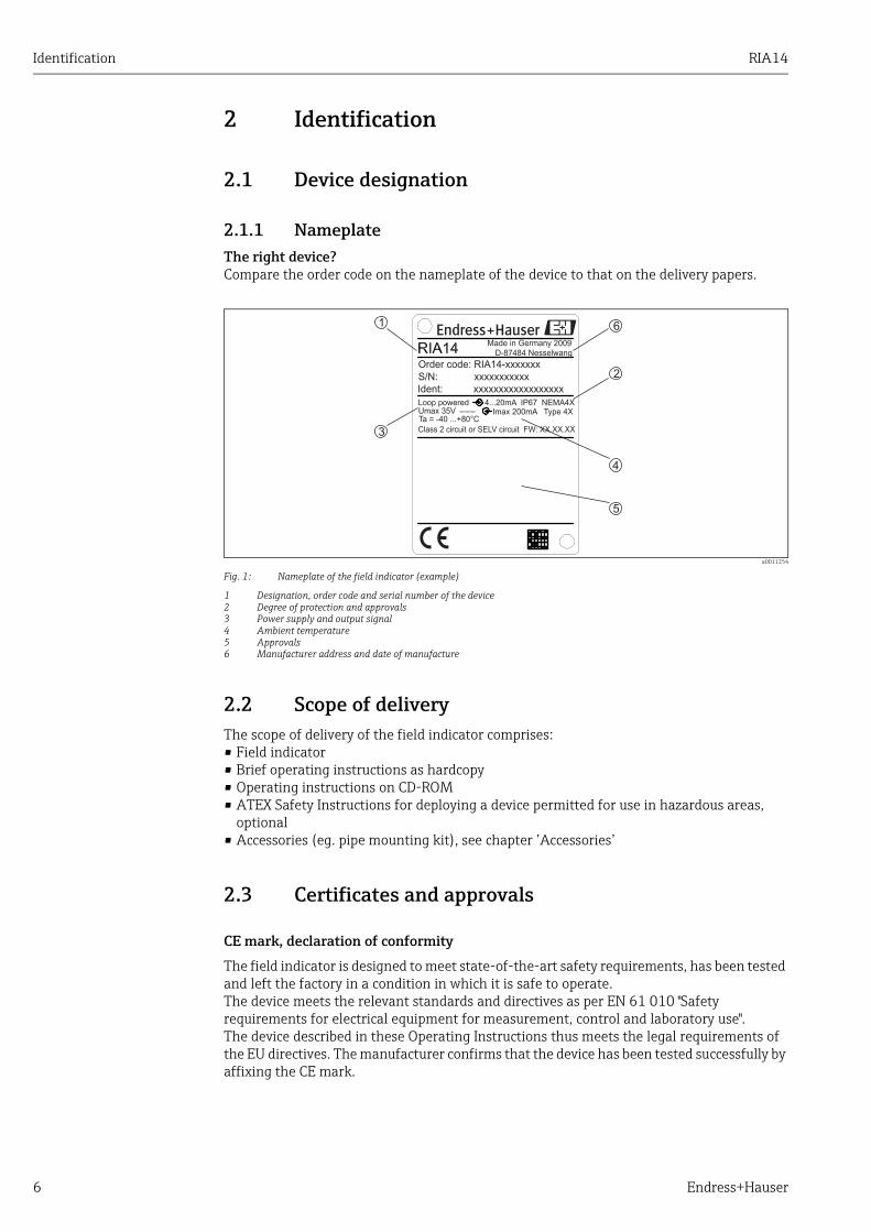
Fig. 1: Nameplate of the field indicator (example)
1 Designation, order code and serial number of the device2 Degree of protection and approvals3 Power supply and output signal4 Ambient temperature5 Approvals6 Manufacturer address and date of manufacture
2.2 Scope of deliveryThe scope of delivery of the field indicator comprises:• Field indicator• Brief operating instructions as hardcopy• Operating instructions on CD-ROM• ATEX Safety Instructions for deploying a device permitted for use in hazardous areas,
optional• Accessories (eg. pipe mounting kit), see chapter ’Accessories’
2.3 Certificates and approvals
CE mark, declaration of conformity
The field indicator is designed to meet state-of-the-art safety requirements, has been tested and left the factory in a condition in which it is safe to operate.The device meets the relevant standards and directives as per EN 61 010 "Safety requirements for electrical equipment for measurement, control and laboratory use".The device described in these Operating Instructions thus meets the legal requirements of the EU directives. The manufacturer confirms that the device has been tested successfully by affixing the CE mark.
1
3
4
2
5
Made in Germany 2009D-87484 Nesselwang
Order code: RIA14-xxxxxxx
S/N: xxxxxxxxxxx
Ident: xxxxxxxxxxxxxxxxxx
Loop poweredUmax 35VTa = -40 ...+80°C
Class 2 circuit or SELV circuit FW: XX.XX.XX
4
4...20mA IP67 NEMA4XImax 200mA Type 4X
6
RIA14 Function and system design
Endress+Hauser 7
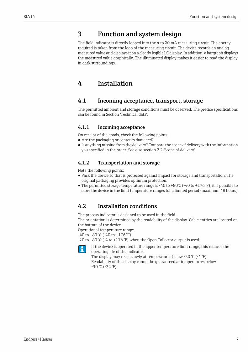
3 Function and system designThe field indicator is directly looped into the 4 to 20 mA measuring circuit. The energy required is taken from the loop of the measuring circuit. The device records an analog measured value and displays it on a clearly legible LC display. In addition, a bargraph displays the measured value graphically. The illuminated display makes it easier to read the display in dark surroundings.
4 Installation
4.1 Incoming acceptance, transport, storageThe permitted ambient and storage conditions must be observed. The precise specifications can be found in Section "Technical data".
4.1.1 Incoming acceptanceOn receipt of the goods, check the following points:• Are the packaging or contents damaged?• Is anything missing from the delivery? Compare the scope of delivery with the information
you specified in the order. See also section 2.2 "Scope of delivery".
4.1.2 Transportation and storageNote the following points:• Pack the device so that is protected against impact for storage and transportation. The
original packaging provides optimum protection.• The permitted storage temperature range is -40 to +80°C (-40 to +176 °F); it is possible to
store the device in the limit temperature ranges for a limited period (maximum 48 hours).
4.2 Installation conditionsThe process indicator is designed to be used in the field.The orientation is determined by the readability of the display. Cable entries are located on the bottom of the device.Operational temperature range: -40 to +80 °C (-40 to +176 °F)-20 to +80 °C (-4 to +176 °F) when the Open Collector output is used
If the device is operated in the upper temperature limit range, this reduces the operating life of the indicator.The display may react slowly at temperatures below -20 °C (-4 °F).Readability of the display cannot be guaranteed at temperatures below -30 °C (-22 °F).
Installation RIA14
8 Endress+Hauser
4.2.1 Dimensions
a0011152
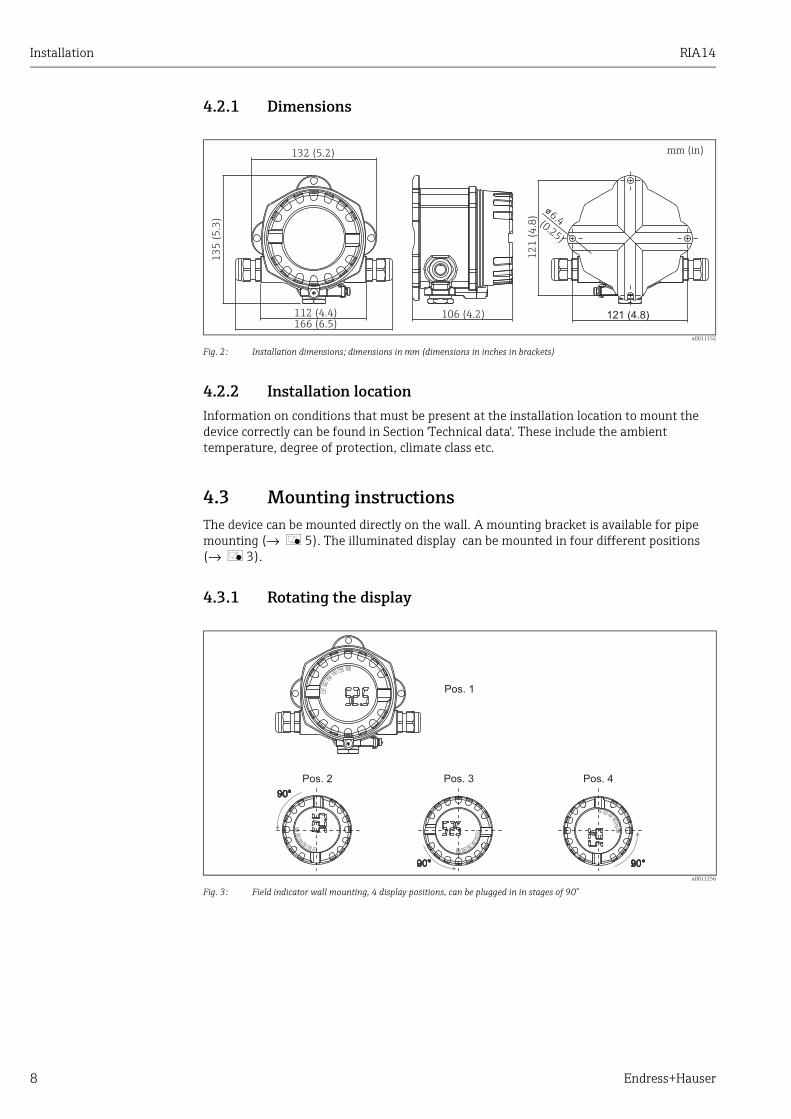
Fig. 2: Installation dimensions; dimensions in mm (dimensions in inches in brackets)
4.2.2 Installation locationInformation on conditions that must be present at the installation location to mount the device correctly can be found in Section 'Technical data'. These include the ambient temperature, degree of protection, climate class etc.
4.3 Mounting instructionsThe device can be mounted directly on the wall. A mounting bracket is available for pipe mounting (→ å 5). The illuminated display can be mounted in four different positions (→ å 3).
4.3.1 Rotating the display
a0011256
Fig. 3: Field indicator wall mounting, 4 display positions, can be plugged in in stages of 90°
RIA14 Installation
Endress+Hauser 9
a0011257
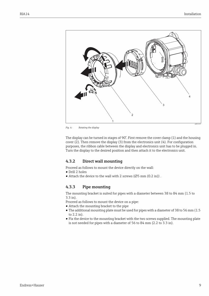
Fig. 4: Rotating the display
The display can be turned in stages of 90°. First remove the cover clamp (1) and the housing cover (2). Then remove the display (3) from the electronics unit (4). For configuration purposes, the ribbon cable between the display and electronics unit has to be plugged in.Turn the display to the desired position and then attach it to the electronics unit.
4.3.2 Direct wall mountingProceed as follows to mount the device directly on the wall:• Drill 2 holes• Attach the device to the wall with 2 screws (∅5 mm (0.2 in)) .
4.3.3 Pipe mountingThe mounting bracket is suited for pipes with a diameter between 38 to 84 mm (1.5 to 3.3 in).Proceed as follows to mount the device on a pipe:• Attach the mounting bracket to the pipe• The additional mounting plate must be used for pipes with a diameter of 38 to 56 mm (1.5
to 2.2 in).• Fix the device to the mounting bracket with the two screws supplied. The mounting plate
is not needed for pipes with a diameter of 56 to 84 mm (2.2 to 3.3 in).
2
3
1
4
Installation RIA14
10 Endress+Hauser
a0011258
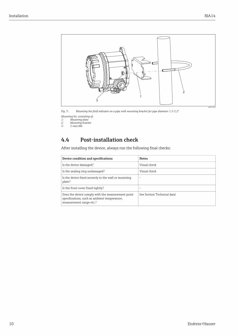
Fig. 5: Mounting the field indicator on a pipe with mounting bracket for pipe diameter 1.5-2.2"
Mounting kit, consisting of:1: Mounting plate2: Mounting bracket3: 2 nuts M6
4.4 Post-installation checkAfter installing the device, always run the following final checks:
Device condition and specifications Notes
Is the device damaged? Visual check
Is the sealing ring undamaged? Visual check
Is the device fixed securely to the wall or mounting plate?
-
Is the front cover fixed tightly? -
Does the device comply with the measurement point specifications, such as ambient temperature, measurement range etc.?
See Section 'Technical data'
RIA14 Wiring
Endress+Hauser 11
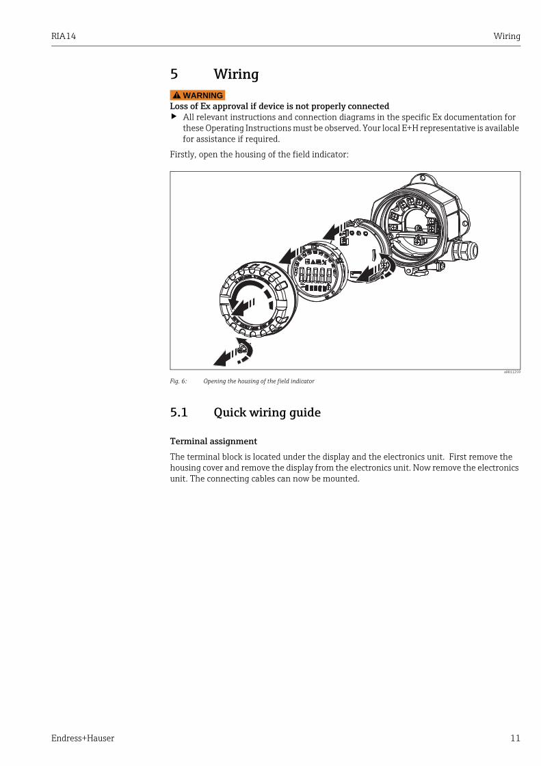
5 WiringWARNING!
Loss of Ex approval if device is not properly connected‣ All relevant instructions and connection diagrams in the specific Ex documentation for
these Operating Instructions must be observed. Your local E+H representative is available for assistance if required.
Firstly, open the housing of the field indicator:
a0011259
Fig. 6: Opening the housing of the field indicator
5.1 Quick wiring guide
Terminal assignment
The terminal block is located under the display and the electronics unit. First remove the housing cover and remove the display from the electronics unit. Now remove the electronics unit. The connecting cables can now be mounted.

Wiring RIA14
12 Endress+Hauser
a0010946-en
Fig. 7: Terminal assignment
5.2 Electrical connectionBoth the terminal assignment and the connection values of the field indicator correspond to those of the Ex-version. The device is only designed for operation in a 4 - 20 mA measuring circuit. There must be potential equalisation along the circuits (within and outside the hazardous area).
Terminal Terminal assignment Input and output
+ Measuring signal (+) 4 to 20 mA Signal input
- Measuring signal (-) 4 to 20 mA Signal input
1 Terminal for further instrumentation Support terminal
2 Digital limit switch (collector) Switch output
3 Digital limit switch (emitter) Switch output
RIA14 Wiring
Endress+Hauser 13
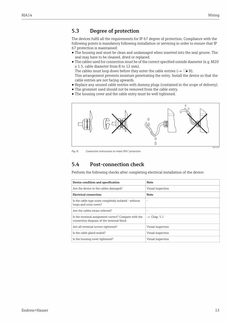
5.3 Degree of protectionThe devices fulfil all the requirements for IP 67 degree of protection. Compliance with the following points is mandatory following installation or servicing in order to ensure that IP 67 protection is maintained:• The housing seal must be clean and undamaged when inserted into the seal groove. The
seal may have to be cleaned, dried or replaced.• The cables used for connection must be of the correct specified outside diameter (e.g. M20
x 1.5, cable diameter from 8 to 12 mm). The cables must loop down before they enter the cable entries (→ å 8). This arrangement prevents moisture penetrating the entry. Install the device so that the cable entries are not facing upwards.
• Replace any unused cable entries with dummy plugs (contained in the scope of delivery).• The grommet used should not be removed from the cable entry.• The housing cover and the cable entry must be well tightened.
a0011260
Fig. 8: Connection instructions to retain IP67 protection
5.4 Post-connection checkPerform the following checks after completing electrical installation of the device:
Device condition and specification Note
Are the device or the cables damaged? Visual inspection
Electrical connection Note
Is the cable type route completely isolated - without loops and cross-overs?
-
Are the cables strain relieved? -
Is the terminal assignment correct? Compare with the connection diagram of the terminal block
→ Chap. 5.1
Are all terminal screws tightened? Visual inspection
Is the cable gland sealed? Visual inspection
Is the housing cover tightened? Visual inspection

Operating the field indicator RIA14
14 Endress+Hauser
6 Operating the field indicator
6.1 Display and operating elements
6.1.1 Display
a0011157
Fig. 9: LC display of the field indicator (can be plugged in in stages of 90°)
6.1.2 Display symbols
6.2 Configuration via operating keysWARNING!
Loss of explosion protection when housing is open‣ The device must be configured outside the hazardous area.
a0011261
Fig. 10: Operating keys of field indicator ("-", "+", "E")
1 Bargraph display
1a Indicator for measuring range undershoot
1b Indicator for measuring range overshoot
2 Measured value displayDigit height 20.5 mm (0.8")
3 14-segment display for units and messages)
4 Symbol ’Programming disabled’
5 Unit ’%’
6 'Fault' indicator

RIA14 Operating the field indicator
Endress+Hauser 15
To configure the device, first remove the housing cover. Then remove the display from the electronics unit. The keys (+, -, E) can now be accessed.During configuration, the display must be connected to the electronics unit. Afterwards, the display can be positioned at the desired angle.
6.2.1 Navigation
The operating fields are split into 2 levels.
Menu: Various menu items can be selected on the menu level. The individual menu items are an aggregation of the associated operating functions.Operating function: An operating function can be regarded as an aggregation of the operating parameters. The operating functions are used to operate and configure the device.
Operating keys:
'E' Enter key: Press and hold down the E key for longer than 3 seconds to enter the programming menu.– Selecting operating functions.– Accepting values.– If the E key is pressed for longer than 3 seconds, the system returns directly to the Home
position. Beforehand, you are asked whether the data entered up to now should be saved.– Saving data entered.
Selection keys ’+/-’: – Selecting the menus.– Configuring parameters and numerical values.– After selecting the operating function, the value is entered or the setting changed by
pressing the + or - keys.
If the keys are pressed for an extended period, the digits are changed with increasing speed.If the + or - keys are pressed in the "Program Name" and "Program Version" operating position, the display is scrolled horizontally as these positions (7-digit) cannot be displayed completely in the 14-segment display.
Operating the field indicator RIA14
16 Endress+Hauser
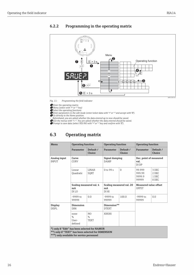
6.2.2 Programming in the operating matrix
a0011262-en
Fig. 11: Programming the field indicator
w Enter the operating matrixx Menu (select with "+" or "-" key)y Select the operating functionsz Enter parameters in the edit mode (enter/select data with "+" or "-" and accept with "E").{ Go directly to the Home position. – Beforehand, you are asked whether the data entered up to now should be saved.| Exit the menus with "+/-". You are asked whether the data entered should be saved.} Prompt to save data (select YES/NO with "+" or "-" key and confirm with "E").
6.3 Operating matrix
Menu Operating function Operating function Operating function
Parameter Default / Choice
Parameter Default / Choice
Parameter Default / Choice
Analog inputINPUT
CurveCURV
Signal dampingDAMP
Dec. point of measured val.DI DP
LinearQuadratic
LINARSQRT
0 to 99 s 0 99.999999.999999.999999
3 DEC2 DEC1 DEC0 DEC
Scaling measured val. 4 mADI LO
Scaling measured val. 20 mADI HI
Measured value offsetOFFST
-9999 to 99999
0.0 -9999 to 99999
100.0 -9999 to 99999
0.0
DisplayDISPL
DimensionDIM
Dimension**DTEXT
none%User-defined
NO%TEXT
XXXXX
*) only if “Edit” has been selected for NAMUR**) only if “TEXT” has been selected for DIMENSION***) only available for service personnel
RIA14 Operating the field indicator
Endress+Hauser 17
6.4 Configuration via interface & FieldCare Device Setup PC configuration software
WARNING!
Loss of explosion protection when housing is open‣ The device must be configured outside the hazardous area.
CAUTION!
Undefined switching of outputs and relays during configuration‣ While configuring with FieldCare the device may assume undefined states.
To configure the device with the FieldCare Device Setup software, connect the device to your PC. You need a special interface adapter for this purpose - the Commubox FXA291 (see Chapter ’Accessories’).The 4-pin connector of the interface cable must be plugged into the corresponding socket inside the device and the USB connector must be plugged into a free USB slot on the PC.
LimitLIMIT
Operating modeMODE
Switching setpointSETP
offMin.safety with alarmMax.safety with alarmAlarm
OFFMIN
MAX
ALARM
-9999 to 99999
0.0
HysteresisHYST
Response delayDELY
-9999 to 99999
0.0 0-99 s 0
Operating parametersPARAM
User codeCODE
Program namePNAME
Firmware versionFWVER
0000 to 9999
0000
NAMURNAMUR
NAMUR 3.6*N_360
NAMUR 3.80*N_380
DefaultEdit
dEFEdit
0 to NAMUR 20.5
3.60 NAMUR 3.6 to NAMUR 20.5
3.80
NAMUR 20.5*N2050
NAMUR 21.0*N2100
TestTEST
NAMUR 3.80 to NAMUR 21.0
20.50 NAMUR 20.5 to 25 mA
21.00 offOpen Collect.Display
OFFOUTDISP
ServiceSERV
Service codeSCODE
Parameter reset***PRSET
- - - - YesNo
YesNo
Menu Operating function Operating function Operating function
Parameter Default / Choice
Parameter Default / Choice
Parameter Default / Choice
*) only if “Edit” has been selected for NAMUR**) only if “TEXT” has been selected for DIMENSION***) only available for service personnel

Operating the field indicator RIA14
18 Endress+Hauser
Connection establishmentWhen connecting the device, the device DTM is not automatically loaded in FieldCare, i.e. the device has to be added manually.
• Firstly, add the Communication DTM "PCP (Readwin) TXU10 / FXA291" to an empty project.
• In the Comm DTM settings, set the baud rate to 2400 baud and select the COM-port used.• Add the RIA14/16 Version Vx.xx.xx device DTM to the project using the "Add device..."
function.Online configuration is not possible with the RIA14/RIA16.
• To then configure the device itself, follow these Operating Instructions for the device. The entire Setup menu, i.e. all the parameters listed in these Operating Instructions, can also be found in the FieldCare Device Setup.
a0011264-en
Fig. 12: Configuring the field indicator via interface adapter
In general, it is possible to overwrite parameters with the FieldCare PC software and the appropriate device DTM even if access protection is active.If access protection by means of a code should be extended to the software, this function should be activated in the extended device setup.
RIA14 Device configuration
Endress+Hauser 19
7 Device configuration
Description of operating functions
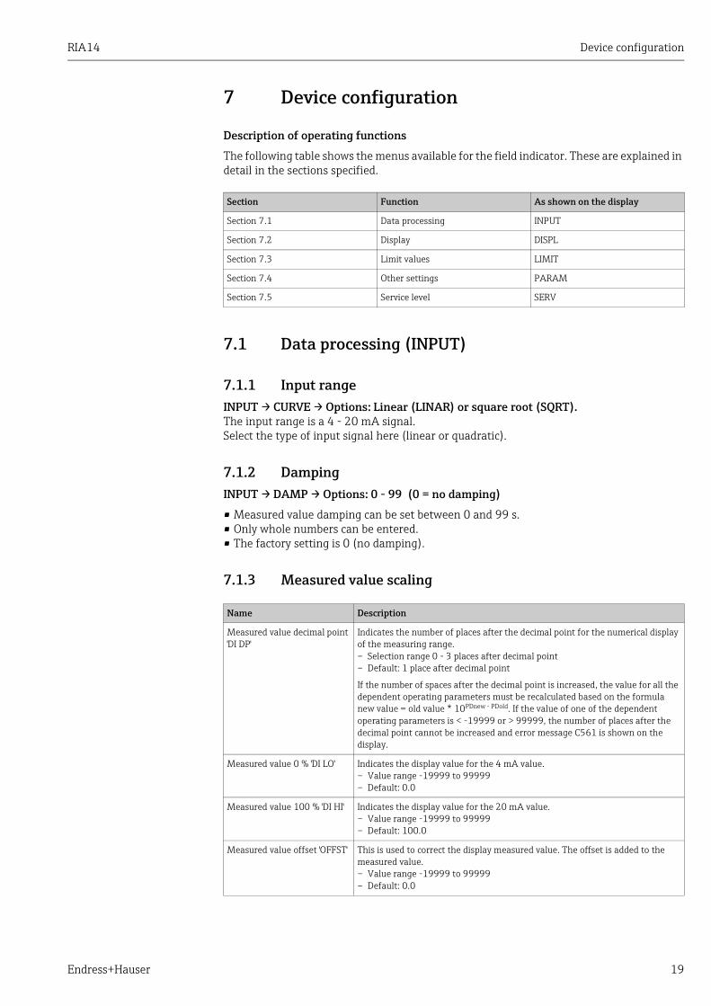
The following table shows the menus available for the field indicator. These are explained in detail in the sections specified.
7.1 Data processing (INPUT)
7.1.1 Input rangeINPUT → CURVE → Options: Linear (LINAR) or square root (SQRT).The input range is a 4 - 20 mA signal.Select the type of input signal here (linear or quadratic).
7.1.2 DampingINPUT → DAMP → Options: 0 - 99 (0 = no damping)
• Measured value damping can be set between 0 and 99 s.• Only whole numbers can be entered.• The factory setting is 0 (no damping).
7.1.3 Measured value scaling
Section Function As shown on the display
Section 7.1 Data processing INPUT
Section 7.2 Display DISPL
Section 7.3 Limit values LIMIT
Section 7.4 Other settings PARAM
Section 7.5 Service level SERV
Name Description
Measured value decimal point 'DI DP'
Indicates the number of places after the decimal point for the numerical display of the measuring range.– Selection range 0 - 3 places after decimal point– Default: 1 place after decimal point
If the number of spaces after the decimal point is increased, the value for all the dependent operating parameters must be recalculated based on the formula new value = old value * 10PDnew - PDold. If the value of one of the dependent operating parameters is < -19999 or > 99999, the number of places after the decimal point cannot be increased and error message C561 is shown on the display.
Measured value 0 % 'DI LO' Indicates the display value for the 4 mA value.– Value range -19999 to 99999– Default: 0.0
Measured value 100 % 'DI HI' Indicates the display value for the 20 mA value.– Value range -19999 to 99999– Default: 100.0
Measured value offset 'OFFST' This is used to correct the display measured value. The offset is added to the measured value.– Value range -19999 to 99999– Default: 0.0

Device configuration RIA14
20 Endress+Hauser
7.2 Display (DISPL)
7.2.1 DimensionDIM → Options: NO, °C, K, °F, % or TEXTOne of the units permanently stored in the display can be selected - K, °C, °F, %. Alternatively, any unit can be configured on the 14-segment display (TEXT).The character set consists of the following characters:Characters A-Z, abcdhijlmnoruvwy, the digits 0-9 and the special characters: - + * / ( )
7.2.2 Configuring the editable unit (DTEXT)
DIM → DTEXT → Enter a unit that can be edited as required
To configure the editable unit, all 5 points on the 14-segment display have to be configured. Press the E key to move on to edit the next letter. Accept the set unit with "E".
a0011266-en
Fig. 13: Configuring the editable unit
Measured value 0 % and 100 % may not be identical. However, the 0 % measured value can be larger than the 100 % measured value (invert).
No. Description
w Press the E key to select the desired operating function.
x Press the E key to select the next point of the 5-digit 14-segment display.
y Press the + or - key to select the next/previous character for the point selected.
z If you press the +/- keys simultaneously, data entry is aborted and the operating function is displayed.
{ When you confirm the 5th position of the display with E, the entry is accepted and you change back to the operating function.
RIA14 Device configuration
Endress+Hauser 21
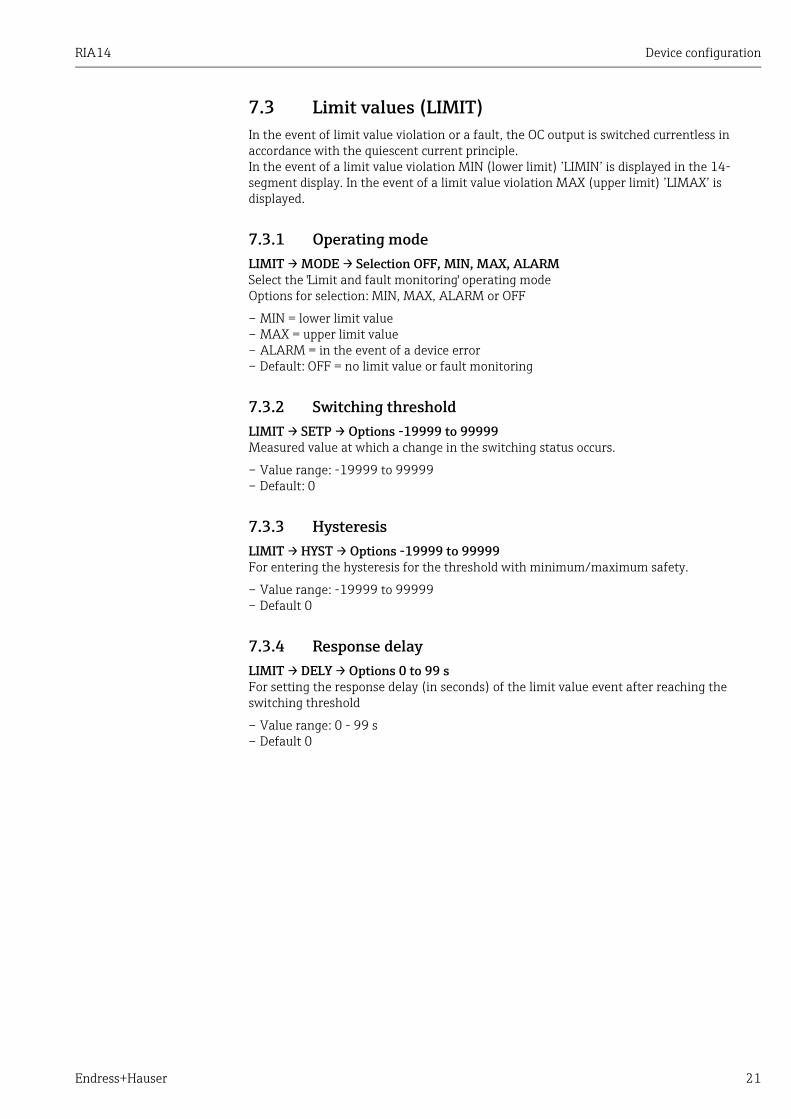
7.3 Limit values (LIMIT)In the event of limit value violation or a fault, the OC output is switched currentless in accordance with the quiescent current principle.In the event of a limit value violation MIN (lower limit) ’LIMIN’ is displayed in the 14-segment display. In the event of a limit value violation MAX (upper limit) ’LIMAX’ is displayed.
7.3.1 Operating modeLIMIT → MODE → Selection OFF, MIN, MAX, ALARMSelect the 'Limit and fault monitoring' operating modeOptions for selection: MIN, MAX, ALARM or OFF
– MIN = lower limit value– MAX = upper limit value– ALARM = in the event of a device error– Default: OFF = no limit value or fault monitoring
7.3.2 Switching thresholdLIMIT → SETP → Options -19999 to 99999Measured value at which a change in the switching status occurs.
– Value range: -19999 to 99999– Default: 0
7.3.3 HysteresisLIMIT → HYST → Options -19999 to 99999For entering the hysteresis for the threshold with minimum/maximum safety.
– Value range: -19999 to 99999– Default 0
7.3.4 Response delayLIMIT → DELY → Options 0 to 99 sFor setting the response delay (in seconds) of the limit value event after reaching the switching threshold
– Value range: 0 - 99 s– Default 0

Device configuration RIA14
22 Endress+Hauser
7.4 Other settings (PARAM)
7.4.1 User code - lockingPARAM → CODE → User code entryThe device can be locked to protect the processes against undesired and unauthorised effects. The device parameters are protected by a 4-digit user code and cannot be altered without entering the code.User code: a user code already assigned can only be altered if the old code is entered to enable the device. The new code can then be configured.
• Value range: 0000 to 9999• Default: 0
7.4.2 Program information
7.4.3 Alarm limits (NAMUR)PARAM → NAMURThe alarm limits are set to NAMUR values at the factory.These values can– be used as default values (DEF) or– be edited freely (EDIT)
The following operating positions can be altered if operating item 'Edit' was selected.
The Namur limits are indicated in ascending order.
7.4.4 Test (TEST)PARAM → TEST → Options OFF, OUT, DISPCertain device functions can be tested automatically.OFF (default)Open collector: OUTDisplay: DISP
Name Description
Program name 'PNAME' Displays the name of the software loaded in the device (7-digit)
Note! Display cannot be edited
Firmware version 'FWVER' Displays the version of the firmware loaded in the device (8-digit)
Note! Display cannot be edited
Press the + or - key to scroll horizontally through the 7 or 8-digit display values.
Name Description
NAMUR 3.6 Value range: 0 mA to < Namur 3.8Default: 3.60
NAMUR 3.8 Value range: Namur 3.6 < x < Namur 20.5Default: 3.80
NAMUR 20.5 Value range: Namur 3.8 < x < Namur 21.0Default: 20.50
NAMUR 21.0 Value range: Namur 20.5 < x < 25 mADefault: 21.00
RIA14 Device configuration
Endress+Hauser 23
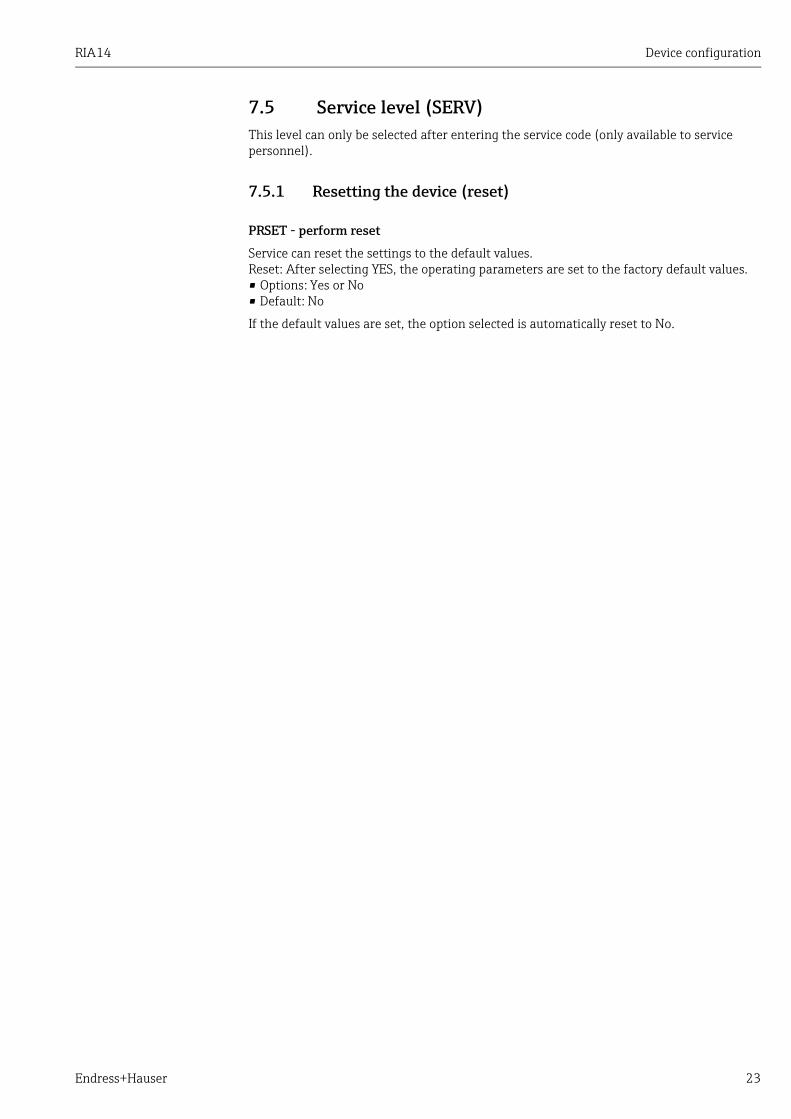
7.5 Service level (SERV) This level can only be selected after entering the service code (only available to service personnel).
7.5.1 Resetting the device (reset)
PRSET - perform reset
Service can reset the settings to the default values.Reset: After selecting YES, the operating parameters are set to the factory default values.• Options: Yes or No• Default: No
If the default values are set, the option selected is automatically reset to No.

Commissioning RIA14
24 Endress+Hauser
8 Commissioning
8.1 Function checkPrior to commissioning, the screw cap must be tightened and secured with the cover clamp. Any openings not used must be sealed.Make sure all connected wires are secure.To ensure correct functioning, the screws of the terminals must be tightened. The device is now operational.
During device initialization, all the segments are shown on the display for approx. 1 second.
RIA14 Maintenance
Endress+Hauser 25
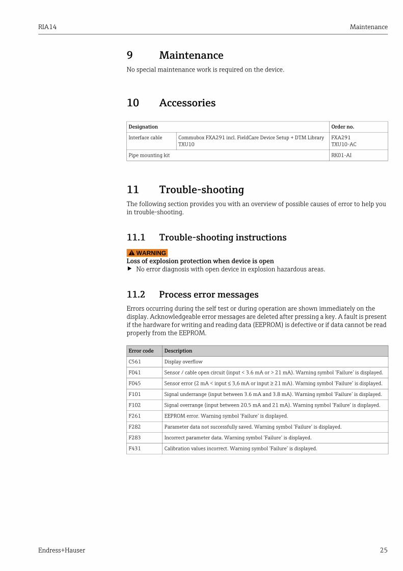
9 MaintenanceNo special maintenance work is required on the device.
10 Accessories
11 Trouble-shootingThe following section provides you with an overview of possible causes of error to help you in trouble-shooting.
11.1 Trouble-shooting instructionsWARNING!
Loss of explosion protection when device is open‣ No error diagnosis with open device in explosion hazardous areas.
11.2 Process error messagesErrors occurring during the self test or during operation are shown immediately on the display. Acknowledgeable error messages are deleted after pressing a key. A fault is present if the hardware for writing and reading data (EEPROM) is defective or if data cannot be read properly from the EEPROM.
Designation Order no.
Interface cable Commubox FXA291 incl. FieldCare Device Setup + DTM LibraryTXU10
FXA291TXU10-AC
Pipe mounting kit RK01-AI
Error code Description
C561 Display overflow
F041 Sensor / cable open circuit (input < 3.6 mA or > 21 mA). Warning symbol ’Failure’ is displayed.
F045 Sensor error (2 mA < input ≤ 3,6 mA or input ≥ 21 mA). Warning symbol ’Failure’ is displayed.
F101 Signal underrange (input between 3.6 mA and 3.8 mA). Warning symbol ’Failure’ is displayed.
F102 Signal overrange (input between 20.5 mA and 21 mA). Warning symbol ’Failure’ is displayed.
F261 EEPROM error. Warning symbol ’Failure’ is displayed.
F282 Parameter data not successfully saved. Warning symbol ’Failure’ is displayed.
F283 Incorrect parameter data. Warning symbol ’Failure’ is displayed.
F431 Calibration values incorrect. Warning symbol ’Failure’ is displayed.

Trouble-shooting RIA14
26 Endress+Hauser
11.3 Spare parts
a0012133
Fig. 14: Spare parts of the field indicator
Pos. no.1 Housing RIA14
Certification:A Non hazardous areas + Ex nAB Ex d
Material:A AluminumB Stainless steel 316L
Cable Entry:1 3x thread NPT1/2, w/o terminal block2 3x thread M20x1.5, w/o terminal block3 3x thread G1/2, w/o terminal block
Model:A Standard
RIA141G- A ⇐ Order code complete, housing RIA14
Pos. no. Order number Designation
2 TMT142X-HC Housing cover cpl. display, 316L, Ex d, FM XP, CSA XP, with O-ring
TMT142X-HD Housing cover cpl. display, 316L with O-Ring
RIA141X-HK Housing cover cpl. display, Alu Ex d + O-ring
3 51004555 O-ring 88x3 NBR70 PTFE coated
4 RIA14X-DA Display + fitting kit + twist protection
RIA141X-DC Display fitting kit + twist protection
51004454 Display fitting kit field housing
5 RIA141X-EA Electronic
6 RIA141X-KA Terminal block
7 51004948 Cover latch spares kit field housing; Screw, washer, spring washer
8 51004949 Cable entry M20x1.5
9 51006888 Blanks (blind) NPT1/2" V4A
51004490 Blanks (blind) NPT1/2" aluminum
51004916 Blanks (blind) G1/2" EEx-d/XP
51004489 Blanks (blind) M20x1.5 EEx-d/XP

RIA14 Technical data
Endress+Hauser 27
11.4 ReturnTo reuse later or in case of repair, the device must be packed in protective packaging, preferably the original packaging. Repairs must only be carried out by your supplier's service organisation or specially trained personnel. Enclose a note describing the fault when sending the unit in for repair.
11.5 DisposalThe device contains electronic components and must, therefore, be disposed of as electronic waste in the event of disposal. Please observe in particular the local waste disposal regulations of your country.
12 Technical data
12.0.1 Input
Measured variable
Current
Measuring range
4 to 20 mA (reverse polarity protection)
Input
• Line voltage drop < 4 V at 3 - 22 mA• Max. line voltage drop < 6 V at max. short-circuit current 200 mA
12.0.2 Output
Output
Digital limit switchPassive, open collector: Imax = 200 mAUmax= 35 VUlow/max = < 2 V at 200 mAMax. reaction time to limit value = 250 msTemperature range: -20 to +80 °C (-4 to +176 °F)
Signal on alarm
• No measured value visible on the LC display, no background illumination.• Open Collector inactive.
Transmission behavior
The indicator allows the HART® transmission protocol to pass unimpeded.
12.0.3 Power supply
Supply voltage
Supply by means of the 4 to 20 mA current loop.
Technical data RIA14
28 Endress+Hauser
Cable entry
The following cable entries are available:
• Thread NPT1/2• Thread M20• Thread G1/2• 2x gland NPT1/2 + 1x blind plug• 2x gland M20 + 1x blind plug
12.0.4 Performance characteristics
Reference operating conditions
T= 25 °C (77 °F)
Maximum measured error
< 0.1% of scaled display range
Influence of ambient temperature (temperature drift)
Effect on the accuracy when ambient temperature changes by 1 K (1.8 °F): 0.01%
12.0.5 Installation
Installation instructions
Mounting locationWall or pipe mounting (see 'Accessories')OrientationNo restrictions, the orientation is determined by the readability of the display.
12.0.6 Environment
Ambient temperature limits
-40 to +80 °C (-40 to +176 °F)-20 to +80 °C (-4 to +176 °F) when the Open Collector output is used
Storage temperature
-40 to +80 °C (-40 to +176 °F)
Electrical safety
As per IEC 61010-1,UL61010-1,CSA C22.2 No. 1010.1-92
Climate class
As per IEC 60 654-1, Class C
Degree of protection
IP 67, NEMA 4X (not evaluated by UL)
The display can react slowly for temperatures < -20 °C (< -4 °F).Readability of the display cannot be guaranteed at temperatures < -30 °C (-22 °F).
RIA14 Technical data
Endress+Hauser 29
Shock and vibration resistance
3g / 2 to 150 Hz as per IEC 60 068-2-6
Condensation
Permitted
Installation category
1 to IEC 61010
Pollution degree
2 to IEC 61010
Electromagnetic compatibility (EMC)
• EN 61326 (IEC 61326):Electromagnetic compatibility (EMC requirements)
• NAMUR (NE21):Association for Standards for Control and Regulation in the Chemical Industry
12.0.7 Mechanical construction
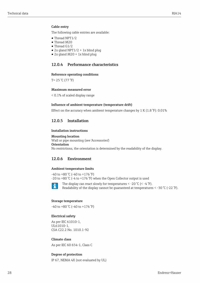
Design, dimensions
Die cast aluminum housing for general purpose or as option stainless steel housing
a0011152
Fig. 15: Data in mm (data in inches in brackets)
• Electronics compartment and connection compartment together in the single chamber housing
• Display can be rotated in 90°-stages
Weight
• Approx. 1.6 kg (3.53 lb) (aluminum housing)• Approx. 4.2 kg (9.26 lb) (stainless steel housing)
Material
Housing Nameplate
Die-cast aluminum AlSi10Mg with powder coating on polyester basis
Aluminum AlMgl, anodized in black
Stainless steel 1.4435 (AISI 316L), as an option 1.4401 (AISI 316)
Technical data RIA14
30 Endress+Hauser
Terminals
Cables / wires up to max. 2.5 mm2 (14 AWG) plus ferrule
12.0.8 Human interface
Display elements
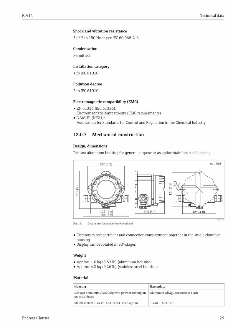
a0011157
Fig. 16: LC display of the field indicator (illuminated, pluggable in 90° stages)
Item 1: bargraph display in increments of 10% with indicators for measuring range undershoot (item 1a)/overshoot (item 1b)Item 2: measured value display, character height 20.5 mm (0.8")Item 3: 14-segment display for units and information messagesItem 4: symbol "programming disabled"Item 5: unit "%"Item 6: warning symbol "failure"
• Display range-19999 to +99999
• Offset-19999 to +99999
• SignallingMeasuring range overshoot/undershoot
• Limit value violationLower/upper limit value exceeded
Operating elements
3-key operation (-/+/E) integrated in device, access with housing open
Remote operation
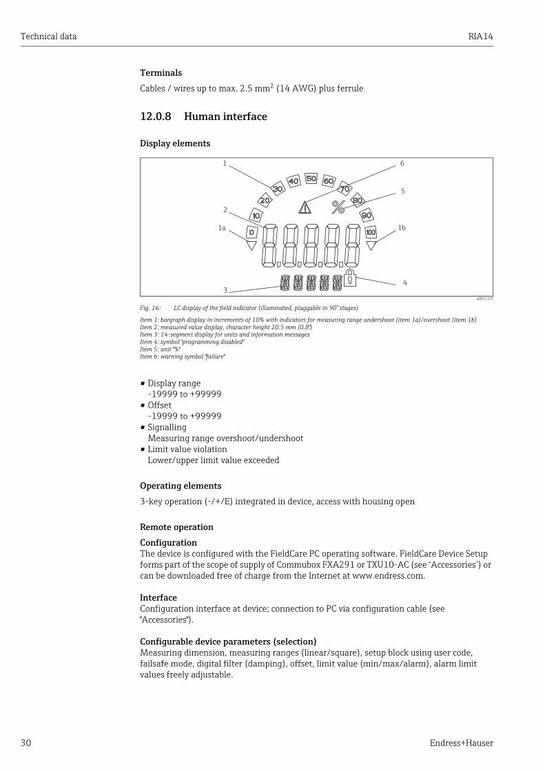
ConfigurationThe device is configured with the FieldCare PC operating software. FieldCare Device Setup forms part of the scope of supply of Commubox FXA291 or TXU10-AC (see ‘Accessories’) or can be downloaded free of charge from the Internet at www.endress.com.
InterfaceConfiguration interface at device; connection to PC via configuration cable (see "Accessories").
Configurable device parameters (selection)Measuring dimension, measuring ranges (linear/square), setup block using user code, failsafe mode, digital filter (damping), offset, limit value (min/max/alarm), alarm limit values freely adjustable.
RIA14 Technical data
Endress+Hauser 31
a0011146-en
Fig. 17: Configuration with PC operating software.
12.0.9 Certificates and approvals
CE mark
The device complies with the legal requirements of the EC directives. Endress+Hauser confirms that the device has been successfully tested by affixing to it the CE mark.
Hazardous area approvals
Information about currently available Ex versions (ATEX, FM, CSA, etc.) can be supplied by your E+H Sales Center on request. All explosion protection data are given in a separate documentation which is available upon request.
Other standards and guidelines
• IEC 60529: Degree of protection by housing (IP-Code)• IEC 61010-1: Safety requirements for electrical measurement, control and laboratory
instrumentation.• IEC 61326-series: Electrical equipment for measurement, control and laboratory use -
EMC requirements.• NAMUR: User association of automation technology in process industries
(www.namur.de)• NEMA: Standardization association for the electrical industry in North America.
UL
Recognized component to UL 3111-1
CSA GP
CSA General Purpose
12.0.10 Documentation
Documentation
• Overview brochure: System Components - Field and Panel-mounted indicators, Energy Managers, Active Barriers, Process Transmitters and Overvoltage Protection: FA016K/09
Technical data RIA14
32 Endress+Hauser
• Ex Safety Instructions:ATEX II2G EEx d: XA085R/09/a3ATEX II1/2D: XA086R/09/a3ATEX II3G: XA087R/09/a3ATEX II2 (1)G Ex ia: XA088R/a3
• Technical Information Field indicator RIA14: TI00143R/09
RIA14
Endress+Hauser 33
Index
AALARM . . . . . . . . . . . . . . . . . . . . . . . . . . . . . . . . . . . . . . . . 21
CCODE . . . . . . . . . . . . . . . . . . . . . . . . . . . . . . . . . . . . . . . . . . 22Configuration via interface. . . . . . . . . . . . . . . . . . . . . . . . 17Connection instructions . . . . . . . . . . . . . . . . . . . . . . . . . . 13
DDAMP . . . . . . . . . . . . . . . . . . . . . . . . . . . . . . . . . . . . . . . . . 19DELY . . . . . . . . . . . . . . . . . . . . . . . . . . . . . . . . . . . . . . . . . . 21DI DP . . . . . . . . . . . . . . . . . . . . . . . . . . . . . . . . . . . . . . . . . . 19DI HI. . . . . . . . . . . . . . . . . . . . . . . . . . . . . . . . . . . . . . . . . . . 19DI LO . . . . . . . . . . . . . . . . . . . . . . . . . . . . . . . . . . . . . . . . . . 19DISPL menu
Editable unit . . . . . . . . . . . . . . . . . . . . . . . . . . . . . . . . . 20Units . . . . . . . . . . . . . . . . . . . . . . . . . . . . . . . . . . . . . . . 20
Display. . . . . . . . . . . . . . . . . . . . . . . . . . . . . . . . . . . . . . . . . 14Turning . . . . . . . . . . . . . . . . . . . . . . . . . . . . . . . . . . . . . . . 8
Display symbols . . . . . . . . . . . . . . . . . . . . . . . . . . . . . . . . . 14DTEXT . . . . . . . . . . . . . . . . . . . . . . . . . . . . . . . . . . . . . . . . . 20
EError code . . . . . . . . . . . . . . . . . . . . . . . . . . . . . . . . . . . . . . 25
FFieldCare Device Setup . . . . . . . . . . . . . . . . . . . . . . . . . . . 17FWVER . . . . . . . . . . . . . . . . . . . . . . . . . . . . . . . . . . . . . . . . 22
HHazardous area . . . . . . . . . . . . . . . . . . . . . . . . . . . . . . . . . . . 4HYST . . . . . . . . . . . . . . . . . . . . . . . . . . . . . . . . . . . . . . . . . . 21
IINPUT menu
Damping . . . . . . . . . . . . . . . . . . . . . . . . . . . . . . . . . . . . 19Input range . . . . . . . . . . . . . . . . . . . . . . . . . . . . . . . . . . 19Measured value scaling. . . . . . . . . . . . . . . . . . . . . . . . 19
LLIMIT menu
Hysteresis . . . . . . . . . . . . . . . . . . . . . . . . . . . . . . . . . . . 21Operating mode . . . . . . . . . . . . . . . . . . . . . . . . . . . . . . 21Response delay. . . . . . . . . . . . . . . . . . . . . . . . . . . . . . . 21Switching threshold. . . . . . . . . . . . . . . . . . . . . . . . . . . 21
LINAR . . . . . . . . . . . . . . . . . . . . . . . . . . . . . . . . . . . . . . . . . 19
MMAX . . . . . . . . . . . . . . . . . . . . . . . . . . . . . . . . . . . . . . . . . . 21Menu
DISPL . . . . . . . . . . . . . . . . . . . . . . . . . . . . . . . . . . . . . . . 20INPUT . . . . . . . . . . . . . . . . . . . . . . . . . . . . . . . . . . . . . . 19LIMIT . . . . . . . . . . . . . . . . . . . . . . . . . . . . . . . . . . . . . . . 21PARAM . . . . . . . . . . . . . . . . . . . . . . . . . . . . . . . . . . . . . 22SERV . . . . . . . . . . . . . . . . . . . . . . . . . . . . . . . . . . . . . . . 23
MIN . . . . . . . . . . . . . . . . . . . . . . . . . . . . . . . . . . . . . . . . . . . 21Mounting
Wall. . . . . . . . . . . . . . . . . . . . . . . . . . . . . . . . . . . . . . . . . . 9
NNameplate . . . . . . . . . . . . . . . . . . . . . . . . . . . . . . . . . . . . . . . 6NAMUR . . . . . . . . . . . . . . . . . . . . . . . . . . . . . . . . . . . . . . . . 22Navigation . . . . . . . . . . . . . . . . . . . . . . . . . . . . . . . . . . . . . . 15
OOFF . . . . . . . . . . . . . . . . . . . . . . . . . . . . . . . . . . . . . . . . . . . . 21OFFST . . . . . . . . . . . . . . . . . . . . . . . . . . . . . . . . . . . . . . . . . . 19Operating functions . . . . . . . . . . . . . . . . . . . . . . . . . . . . . . 19Operating keys. . . . . . . . . . . . . . . . . . . . . . . . . . . . . . . 14–15
PPARAM menu
Alarm limits . . . . . . . . . . . . . . . . . . . . . . . . . . . . . . . . . . 22Locking . . . . . . . . . . . . . . . . . . . . . . . . . . . . . . . . . . . . . . 22Program information . . . . . . . . . . . . . . . . . . . . . . . . . . 22User code . . . . . . . . . . . . . . . . . . . . . . . . . . . . . . . . . . . . 22
PNAME. . . . . . . . . . . . . . . . . . . . . . . . . . . . . . . . . . . . . . . . . 22Programming in the operating matrix . . . . . . . . . . . . . . . 16PRSET . . . . . . . . . . . . . . . . . . . . . . . . . . . . . . . . . . . . . . . . . . 23
SSERV menu
Reset . . . . . . . . . . . . . . . . . . . . . . . . . . . . . . . . . . . . . . . . 23SETP . . . . . . . . . . . . . . . . . . . . . . . . . . . . . . . . . . . . . . . . . . . 21SQRT . . . . . . . . . . . . . . . . . . . . . . . . . . . . . . . . . . . . . . . . . . . 19
TTerminal assignment . . . . . . . . . . . . . . . . . . . . . . . . . . . . . 11TEST . . . . . . . . . . . . . . . . . . . . . . . . . . . . . . . . . . . . . . . . . . . 22TEXT . . . . . . . . . . . . . . . . . . . . . . . . . . . . . . . . . . . . . . . . . . . 20Turning the display . . . . . . . . . . . . . . . . . . . . . . . . . . . . . . . . 8
WWall mounting. . . . . . . . . . . . . . . . . . . . . . . . . . . . . . . . . . . . 9

www.addresses.endress.com