b8090 china en - steering- · pdf filemaintenance report ... so that an endless ball chain is...
TRANSCRIPT

Service
Service
8090 I 04/12 en
Design
Operation
Maintenance
Inspection
ZF-Servocom����
Types 8090, 8095, 8097 und 8098
Troubleshooting with theZF Servotest 7418 798 100
ZF Lenksysteme GmbH
D-73522 Schwäbisch Gmünd
Telephone (07171) 31-0 Telefax (07171) 31-4396

Table of Contents / Safety Note
8090 I 04/12 en 1
Table of Contents
Page
I. Safety Note 1. . . . . . . . . . . . . . . . . . . . . . . . . . . . . . . . . . . . . . . . . . . . . . . . . . . . . . . . . . . . . . . . . .
II. Design and Operation 2. . . . . . . . . . . . . . . . . . . . . . . . . . . . . . . . . . . . . . . . . . . . . . . . . . . . . . .
III. Service Work 7. . . . . . . . . . . . . . . . . . . . . . . . . . . . . . . . . . . . . . . . . . . . . . . . . . . . . . . . . . . . . . . .
1 Notes 7. . . . . . . . . . . . . . . . . . . . . . . . . . . . . . . . . . . . . . . . . . . . . . . . . . . . . . . . . . . . . . . . . . . .
2 Maintenance 8. . . . . . . . . . . . . . . . . . . . . . . . . . . . . . . . . . . . . . . . . . . . . . . . . . . . . . . . . . . . . .
3 Inspection 10. . . . . . . . . . . . . . . . . . . . . . . . . . . . . . . . . . . . . . . . . . . . . . . . . . . . . . . . . . . . . . .
4 Oil change and bleeding 13. . . . . . . . . . . . . . . . . . . . . . . . . . . . . . . . . . . . . . . . . . . . . . . .
5 Setting the hydraulic steering limitation 17. . . . . . . . . . . . . . . . . . . . . . . . . . . . . . . . .
IV. Repair of External Leakages 22. . . . . . . . . . . . . . . . . . . . . . . . . . . . . . . . . . . . . . . . . . . . . . .
V. Removal and Reinstallation of the Steering Gear 23. . . . . . . . . . . . . . . . . . . . . . . . . . .
VI. Special Tools 28. . . . . . . . . . . . . . . . . . . . . . . . . . . . . . . . . . . . . . . . . . . . . . . . . . . . . . . . . . . . .
VII. Trouble Shooting 29. . . . . . . . . . . . . . . . . . . . . . . . . . . . . . . . . . . . . . . . . . . . . . . . . . . . . . . . . .
1 Steering system trouble shooting and checking of the hydraulic functions 29
2 Trouble shooting guide 36. . . . . . . . . . . . . . . . . . . . . . . . . . . . . . . . . . . . . . . . . . . . . . . . .
VIII. Key to numbers in figures and exploded view 38. . . . . . . . . . . . . . . . . . . . . . . . . . . . . .
IX. Maintenance Report 39. . . . . . . . . . . . . . . . . . . . . . . . . . . . . . . . . . . . . . . . . . . . . . . . . . . . . . .
Inspection report 40. . . . . . . . . . . . . . . . . . . . . . . . . . . . . . . . . . . . . . . . . . . . . . . . . . . . . . . . . .
Trouble shooting report 41. . . . . . . . . . . . . . . . . . . . . . . . . . . . . . . . . . . . . . . . . . . . . . . . . . .
I. Safety Note
Attention: Important safety note for the driver or the shop staffWhen the steering system is in good working order the steering efforts the driver has to exert onthe steering wheel (e.g., 30 N corresponding to approx. 3 kg) are low.In the event of a failure of the power assistance (e.g., oil level low) the effort needed for steeringwill increase greatly (for example to 450 N corresponding to approx. 45 kg).
As this will happen very rarely and unexpectedly, the driver may commit the error of believing thatthe steering system cannot be moved any more.However even in the event of a power assistance failure there is always a mechanical connectionbetween the steering wheel and the road wheel which ensures that steering at increased steeringefforts is possible.
To avoid damages inside the steering gear and damages to the steering column, the steering effortat the rim of a steering wheel with a diameter of 500 mm must not exceed 700 N (approx. 70 kg)when steering motions are carried out without steering assistance at vehicle standstill.

Design and Operation
Return pressure
8090 I 04/12 en2
II. Design and Operation
1 Design
The housing of the ZF-Servocom steering gear contains the steering valve, the steering cylinderas well as a complete manual steering gear.
The oil flow and the pressure required by the steering gear is supplied by an engine-driven pump.To achieve this, the oil is taken in from the oil tank and fed back to the tank via the pump andthe steering gear.
The housing (A) - see Fig. 1 - and the piston (B) have the function of a cylinder. The pistontransforms the rotary motion of the steering input shaft (C) and of the worm (D) into an axial motionwhich it transmits to the sector shaft (F).
The piston (B) and the worm (D) are positively connected with each other by means of a ball chain.As the worm (D) rotates, the balls at one end of the chain are taken up by a recirculating tubeand fed to the other end, so that an endless ball chain is formed.
The teeth of the piston (B) and the sector shaft (F) cause the sector shaft to rotate when the pistonis displaced.
Fig. 1Valve rotor inmid-position
A HousingB PistonC Valve rotor/steering input
shaftD Valve sleeve/wormE Torsion barF Sector shaftG Pressure relief valveH Replenishment valveQ Oil tankR Vane pumpS Flow limitation valve

Design and Operation
8090 I 04/12 en 3
The steering valve consists of the valve rotor (C) which is carried in a needle bearing in the worm(D) and is provided with six control grooves on its circumference, and of the valve sleeve (D) onthe worm (D), which is also provided with six control grooves.
A torsion bar (E) pinned to the valve rotor (C) and the worm (D) keeps the steering valve in itsmid-position as long as no effort is exerted on the steering wheel rim.
A pressure relief valve (G) limiting the maximum pressure within the steering system may beintegrated in the steering gear housing.
In addition, a replenishment valve (H) sucking oil from the return oil line when a steering motionwithout hydraulic assistance takes place can be fitted to the housing or to the steering valve.
In comparison with constant ratio steering gears, variable ratio steering gears are more directaround centre than outside the mid-position area, which has a favourable effect on the steeringperformance during straight ahead driving as minor steering corrections only, if any, are required.
At the same time, owing to the indirect steering ratio a higher hydraulic torque is available at thesector shaft in the static parking range which requires a wider steering wheel turning angle.
In the event of a failure of the hydraulic assistance the steering efforts at the steering wheel rimare lower in this range than they would be if the steering gear had a constant ratio.
The 3 functional drawings to Figs. 1 to 3 give a simplified representation of the steering valve andthe oil flow. In addition these illustrations give a cross-sectional view of the steering valve in orderto represent schematically the connections from the steering valve to the cylinder chambers andthe mode of operation of the valve.
2 Operation
When a torque is transmitted from the steering input shaft to the worm or vice-versa, the torsionbar is subjected to a deformation in the elastic area of its length. This causes a torsion to occurbetween the valve rotor and the valve sleeve. The control grooves of the valve rotor are therebymoved away from the mid-position as compared with the position of the control grooves in thevalve sleeve.
When the steering wheel is released the action of the torsion bar will make the steering valvereturn to the neutral (mid) position.
Through the bore in the housing the oil flows into the annular groove of the valve sleeve and isfed through three symmetrically-arranged radial bores to the arcuate control grooves of the valverotor inside the valve sleeve.
The position of the control grooves in the valve rotor and in the valve sleeve is such that, in themid-position of the steering valve, the oil can flow through the inlet slots (J and K) to the axialgrooves (N and O) of the valve sleeve which are also arcuate. From there the oil can flow freelythrough radial bores to the two steering cylinder chambers.
As long as the steering valve is in the mid-position the oil can flow to both cylinder chambers and,via the three return grooves (P) in the valve rotor, it can also flow off to the oil tank.

Design and Operation
Operating pressure
Return pressure
8090 I 04/12 en4
2.1 Forward steering motion to the right (piston with right-handed thread)
Fig. 2Valve rotor in operatingpositionSteering wheel turnedclockwise
J Inlet slotK Inlet slotL Return slotM Return slotN Axial grooveO Axial grooveP Return groove
When the steering wheel is rotated to the right the piston will shift to the right (Fig. 2). A pressurewill now build up in the left-hand cylinder chamber which is a function of the steering effort re-quired.
To achieve this the control grooves of the valve rotor are displaced clockwise and the inlet slots(K) are opened wider to admit the oil, while the inlet slots (J) are closed to the same extent andthus obstruct the feeding of oil to the axial grooves (O) of the valve sleeve.
The oil will now flow through the inlet slots (K) into the axial grooves (N) of the valve sleeve and,from there, will pass through the ball screw thread and flow to the left-hand cylinder chamber. Theclosed inlet slots (J) prevent the oil from flowing off to the oil tank and, thus, cause a pressurebuild-up.
The oil from the right-hand cylinder chamber is displaced and flows to the return grooves (P) ofthe valve rotor via the opened return slots (M). From there it can at any time flow through thecentral oil bore in the valve rotor and the worm, and off to the oil tank.

Design and Operation
Operatingpressure
Returnline pressure
Fig. 3
Valve rotor inoperating position
Steering wheel turnedcounterclockwise
8090 I 04/12 en 5
2.2 Forward steering motion to the left (piston with right-handed thread)
J Inlet slotK Inlet slotL Return slotM Return slotN Axial grooveO Axial grooveP Return groove
When the steering wheel is rotated to the left the piston will shift to the left (Fig. 3). Thereforepressure build-up now takes place in the right-hand cylinder chamber.
The control grooves of the valve rotor are displaced counter-clockwise and allow the oil to flowthrough the opened inlet slots (J) to the axial grooves (O) from where there is a connection to theright-hand cylinder chamber.
The oil from the left-hand cylinder chamber flows to the return grooves (P) of the valve rotor viathe ball screw thread and the opened return slots (L), and can then freely flow off to the oil tankthrough the central oil bore in the valve rotor and the worm.
Design and Operation
Operating pressure
Return line pressure
Reducedoperatingpressure
Return linepressure
8090 I 04/12 en6
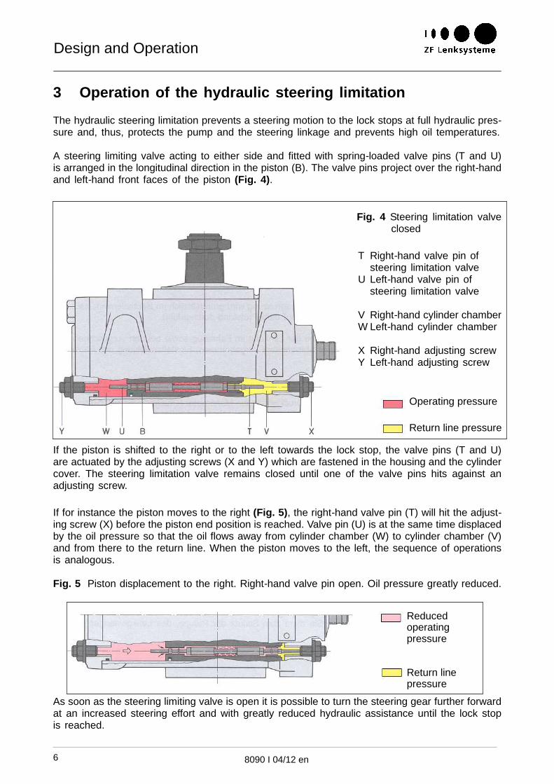
3 Operation of the hydraulic steering limitation
The hydraulic steering limitation prevents a steering motion to the lock stops at full hydraulic pres-sure and, thus, protects the pump and the steering linkage and prevents high oil temperatures.
A steering limiting valve acting to either side and fitted with spring-loaded valve pins (T and U)is arranged in the longitudinal direction in the piston (B). The valve pins project over the right-handand left-hand front faces of the piston (Fig. 4).
Fig. 4 Steering limitation valveclosed
T Right-hand valve pin ofsteering limitation valve
U Left-hand valve pin ofsteering limitation valve
V Right-hand cylinder chamberW Left-hand cylinder chamber
X Right-hand adjusting screwY Left-hand adjusting screw
If the piston is shifted to the right or to the left towards the lock stop, the valve pins (T and U)are actuated by the adjusting screws (X and Y) which are fastened in the housing and the cylindercover. The steering limitation valve remains closed until one of the valve pins hits against anadjusting screw.
If for instance the piston moves to the right (Fig. 5), the right-hand valve pin (T) will hit the adjust-ing screw (X) before the piston end position is reached. Valve pin (U) is at the same time displacedby the oil pressure so that the oil flows away from cylinder chamber (W) to cylinder chamber (V)and from there to the return line. When the piston moves to the left, the sequence of operationsis analogous.
Fig. 5 Piston displacement to the right. Right-hand valve pin open. Oil pressure greatly reduced.
As soon as the steering limiting valve is open it is possible to turn the steering gear further forwardat an increased steering effort and with greatly reduced hydraulic assistance until the lock stopis reached.
Service Work
8090 I 04/12 en 7
III. Service Work
1 Notes
Various countries require by law that a safety test (SP) be carried out for vehicles with more than8 passenger seats or a maximum total weight exceeding 7.5 t.
Attention:
For vehicles not subject to the safety test (SP) additionally carry out the work described in ChapterIII., Service Work, paragraphs 3.5...3.10.
We recommend to carry out the following work after a test drive and a subsequent visual inspec-tion of the complete steering system (steering column, angle drive, steering gear, drag links, pump,and hydraulic lines).
Within the scope of maintenance work a test drive/visual inspection serves to check the properfunctioning of the steering system.
During an inspection safety-critical characteristics are tested.

Service Work
8090 I 04/12 en8
2 Maintenance
Maintenance intervals:We recommend to carry out the following work in the context of the general maintenance work.¡
2.1 Test driving
During the test drive pay special attention to the following characteristics:� Self-alignment� Jamming� Increased friction� Play
2.2 Checking for external leakproofness / damages
Check the steering gear (with bellows), the protecting caps, the pumps (engine-driven and ground-driven), the valves and steering cylinders, the lines and the screwed connections for leakproofnessand damages. A thin oil film may cover the piston rod of the steering cylinder but there must notbe any oil drops.
Note:When cleaning with a high pressure cleaning machine make sure not to aim the water jet directlyon the sealing elements of the steering system. Water and impurities penetrating into the steeringsystem can cause malfunctions.
2.3 Checking the oil level
Oil grade required: see List of Lubricants TE-ML 09
Before pulling out the oil dipstick thoroughly clean the oil tank and its immediate surroundings inorder to prevent impurities from getting into the hydraulic fluid.
Attention:Too low an oil level may entail malfunctions which, in turn, may cause a failure of the steeringsystem power assistance.
¡ see vehicle manufacturer’s instructions

Service Work
8090 I 04/12 en 9
Vehicles equipped with a ZF Servocom RAS (Rear Axle Steering System):
Check the oil level in the straight ahead driving position.
If the oil level is above the top mark there may be a leakage in the master cylinder of the ZFServocom RAS.
Inspect the ZF Servocom RAS as specified in the Instructions on the Operation, Maintenance andInspection of ZF Servocom RAS steering gears.
� Oil level check with the engine cut off:
The oil level must reach the top mark of the oil dipstick.
� Oil level check with the engine running:
When the engine is running the oil level must be between the lower and the upper marks.
When the engine is stopped the oil level may rise by 1...2 cm (depending on the capacity of thesteering system).
The steering system must be bled if the oil level rises by more than 2 cm.
Start the engine.
Vehicles with an additional ground-driven emergency steering pump: jack up the driving axle ofthe emergency steering pump and engage a gear. ¡
¡ see vehicle manufacturer’s instructions

Service Work
8090 I 04/12 en10
3 Inspection
Attention:The inspection intervals depend on the type of use of the vehicle;
therefore the table below distinguishes between different types of use which may, though, beoverlapping.
For more road safety we recommend to inspect the steering system in accordance with the follow-ing inspection intervals.
However these inspection intervals may be adjusted to vehicle-specific intervals if the differencesare only slight.
Note:
Below you will also find work that has to be carried out in the context of the safety test (SP).
This work is marked “(part of SP)”. Within the scope of the standard inspection the inspection stepsmarked thus may therefore be omitted for vehicles which are subject to the safety test (SP).
In addition, the rules governing the safety test (SP) in the respective vehicle registration countriesmust be conformed to.
3.1 Inspection intervals
Type of use First InspectionInspection on the vehicle
Further inspectionsInspection on the vehicle
Long-distance vehiclesMotor coaches with high mileages
600,000 km after a further
300,000 km, ea.
BusesConstruction site vehiclesVehicles in short-distance useVehicles with extreme load profiles
300,000 km7.500 op. hrs.
every 300,000 km7,500 op. hrs.
3.2 Test drive
During the test drive pay special attention to the following characteristics:
� Self-alignment
� Jamming
� Increased friction
� Play
Service Work
8090 I 04/12 en 11
3.3 Visual inspection
� Check the screws and bolts of the complete steering system (steering input line, angle drive,steering gear, drag links, and steering cylinder) for correct fastening.
� Check whether the locking plate and the split pin are still perfectly secured.
� Check whether the drop arm is still sitting tightly on the sector shaft by rotating the steeringwheel alternatingly to either side or by applying a load to it.
� Check the steering input line, the angle drive, the steering gear, the axle stops, the draglinks and the tie rods for damages, cracks, and corrosion.
� Check the external leakproofness of the complete steering system while the engine isrunning.
3.4 Changing the oil filter
Attention:Before taking off the oil tank cover thoroughly clean the oil tank and its immediate surroundingsin order to prevent impurities from getting into the hydraulic fluid.
� Pull the filter insert out of the oil tank.
� Avoid any dripping of oil from the insert into the tank.
� If the oil is heavily soiled, clean the oil tank.
� Fit a new filter insert.
Attention:
Below you will find listed all the work on the steering gear that has to be carried out in the contextof the safety test (SP).
� This list represents the currently applicable state and is not subject to the Updating Service.
3.5 Steering gear play (part of SP)
� Start the engine.
� Rotate the steering wheel to the straight ahead position.
� Slowly rotate the steering wheel away from straight ahead and at the same time look at thefront wheel to see how far the steering wheel has be turned to make the front wheel move.
� Permissible total travel (steering wheel ∅ 500 mm): max. 50 mm
max. 55 mm for versions with angledrive

Service Work
8090 I 04/12 en12
3.6 Hydraulic steering limitation (part of SP)
The hydraulic steering limitation causes the pressure to drop in the area of the steering stop, thusprotecting the steering pump and the steering linkage and preventing high temperatures.
� To check the setting, please refer to Chapter III., paragraph 5.
3.7 Ease of operation of the steering gear (part of SP)
When the steering system has a hydraulic defect, this will make itself felt by increased steeringefforts.
� Start the engine.
� At vehicle standstill, quickly rotate the steering gear twice from lock to lock and lookout for any stiff operation of the steering gear.
3.8 Snap-in points (part of SP)
Defective transmission components such as the steering column, universal joints, etc., may tempo-rarily entail a stiff operation of the steering gear (snap-in points).
� Lift the front axle clear of the ground (following vehicle manufacturer’s instructions).
� With the engine shut off, rotate the steering gear from lock to lock and watch out for snap-inpoints.
3.9 Automatic self-alignment (part of SP)
Automatic self-alignment is taken care of by the axle geometry while the vehicle is driving.� Test drive the vehicle in a restricted area.� During test driving steer the steering gear forward to the stop.� Release the steering wheel and see whether the steering system automatically returns to
the mid-position area.
3.10 Steering wheel (part of SP)
� Check the steering wheel for proper fastening.� Examine the steering wheel for damages.

Service Work
Fig. 6
depending on the version
8090 I 04/12 en 13
4 Oil change and bleeding
4.1 Oil change
4.1.1 Draining the oil
Note:An oil change is only required when units forming part of the steering system were repaired orreplaced.
Do not use any drained oil to refill the system, and avoid any blending of oils.
4.1.2 Draining the steering system
Jack up the steered axle.¡
Unscrew the pressure and return lines from the steering gear.
Then turn the engine on to suck the oil from the vane pump and the oil tank, but not for more than10 seconds maximum. Collect any escaping oil.
Screw in again all components unscrewed earlier.
4.1.3 Draining the steering gear
If existing on the version being serviced, unscrew
� the screw plugs (55) from the cylinder cover or the housing
� the set screw or the collar nut (20 or 128)
� the screw (20.9)
� the bleeder (57) (Fig. 6).
¡ see vehicle manufacturer’s instructions
Service Work
8090 I 04/12 en14
To achieve a quick draining, among the components referred to above open the one which islowest in the installed position.
Rotate the steering gear manually from lock to lock until no more oil is draining.
Unscrewed components must be screwed in again at the following tightening torques:
Screw plug (55): 40 Nm (M16x1.5)
50 Nm (M18x1.5)
Collar nut (21 and 129): 20+10 Nm
Screw (20.9): 12+3 Nm
Bleeder (57): 30 Nm
Note:Even after unscrewing all components mentioned above it may occur that a residual oil quantityis left over in the steering gear.Depending on how soiled the oil is, it may become necessary to completely drain the steeringgear. To this effect the steering gear must be removed from the vehicle and opened at a ZF AfterSales Service Centre.
4.2 Oil filling
Attention:When the steering gear is filled with oil there is a risk of impurities getting into the steering oilcircuit. To avoid malfunctions caused by foreign bodies in the system maximum cleanliness is ofparamount importance both at initial fill and when topping up with oil.
For admitted oil grades refer to List of Lubricants TE-ML 09.
Fill the oil tank with oil until it reaches the rim.
Start the engine and have it run at idling speed to fill the steering system with oil.
During this operation the oil level in the tank will drop fast.
Therefore, to avoid any sucking of air, the oil tank has to be topped up permanently.
In addition, for vehicles with a ground-driven emergency steering pump:
Jack up the driving axle. ¡
Engage a gear and have the engine run at idling speed.
To avoid any sucking of oil top the oil tank up permanently.
¡ see vehicle manufacturer’s instructions

Service Work
8090 I 04/12 en 15
4.3 Bleeding
� For steering gear versions with automatic bleeding:
Steering gear versions with automatic bleeding do not have any bleed screws. These steeringgears automatically bleed any air remaining in the steering system.
Note:Automatic bleed valves operate in the flow pressure range only. Therefore, any unnecessary pres-sure build-up should be avoided.
When the steering system is sufficiently topped up with oil so that the oil level does not drop anymore below the upper mark of the dipstick, have the engine run for 2...3 minutes at low speed.
Rotate the steering wheel several times from lock to lock and, while doing so, watch the oil level.
If required top up with oil.
� In addition, for vehicles with a ground-driven emergency steering pump:
Jack up the driving axle.¡
With a gear engaged and the engine running, bleed the emergency steering pump.
2...3 minutes later rotate the steering wheel several times from lock to lock.
Note:In the end positions do not pull more at the steering wheel than is necessary to rotate the steeringwheel.
If required top up with oil.
� Versions with an additional steering cylinder:
The line ports of the steering cylinder must point upward to allow the air in the cylinder to escape.
If required turn the steering cylinder to a suitable position and mount it again in its original positionafter air bleeding.
¡ see vehicle manufacturer’s instructions

Service Work
Fig. 7depending on the version
Fig. 8
8090 I 04/12 en16
� Ausführungen mit Entlüfter (57):
With the engine running open the bleeder (57) and keep it open until oil only is escaping(Fig. 7).As soon as this is so, close the bleeder again until oil-tight.On versions without automatic bleeding (steering output shaft in the bottom position when installedposition is horizontal) the overhead screw or set screw (20.9/20)) may be used for bleeding.
� Versions with screw (20.9):Open the overhead screw (20.9) and keep it open until oil only is escaping.Retighten the screw (20.9) using a torque of 12+3 Nm.
� Versions with set screw (20):Slacken the collar nut (21) of the overhead set screw (20) until oil only is escaping.Re-tighten the collar nut (21) using a torque of 20+10 Nm.Upon completion of the bleeding operation the hydraulic steering limitation must be checked.
� In addition, for versions with flange (335):
Open the screw plug (335.4) and keep it open until oil only is escaping (Fig. 8).Then close the screw plug again.Tightening torque: 8+1 Nm (M8x1)
� If bleeding was done correctly, the oil level in the oil tank must not rise by more than 1 to2 cm when the engine is turned off.Turn the engine off and lower the jacked-up steered axle and driving axle to the ground.

Service Work
Fig. 9
A
B
Fig. 10
8090 I 04/12 en 17
5 Setting the hydraulic steering limitation
A setting of the steering limitation is necessary if or when
� a new or repaired steering gear is fitted or
� new screws (20.9) were fitted to the automatically adjusting steering limitation or
� alterations to or adjustments of the front axle were made.
5.1 Mechanically adjustable hydraulic steering limitation (Fig. 9)
Install Tool [1] (ZF Servotest) in the pressure line between the pump and the steering gear (seeFig. 10).
1 Pump2 Oil tank3 Pressure line4 Suction line5 Return line6 ZF Servotest
If set right screw (20) is used for adjusting, the drop arm will be caused to move in direction “B”(Fig. 10).If set left screw (20) is used for adjusting, the drop arm will be caused to move in direction “A”.

Service Work
8090 I 04/12 en18
Test temperature: 50±10°C� Rigid axle:
Relieve the axle by jacking it up or place it on swivel plates. ¡
� Independent wheel suspension:
Place the steered wheels on swivel plates.
� With the engine running at idle speed rotate the steering gear to the lock stop using an effortof 100...200 N at the steering wheel rim.
Upon reaching the lock stop, overcome the return force of the steering valve by rotating the steer-ing wheel further forward for a short time (5 sec. maximum) until a positive steering stop isreached.
Read the pressure at Tool [1] (ZF Servotest).
Specified values:
Steering systems Up to 16 dm3/min: 40...50 bar
up to 20 dm3/min: 50...60 bar
in excess of 20 dm3/min: 70...80 bar
To correct, slacken the collar nut (21) and screw the set screw (20) Fig. 9 in or out.
If a higher pressure is measured, the set screw must be screwed in further.
If a lower pressure is measured, the set screw must be screwed out further.
While doing so, release the steering wheel so that during this work flow pressure only can buildup.
Next, re-tighten the collar nut (21) using a torque of 20+10 Nm.
Attention:
During the adjusting operation as well as in the built-in condition the set screws (20) must bescrewed in at least 3 threads deep for otherwise, because of insufficient thread overlap, there isa risk of the set screws being ejected when maximum pressure builds up in the steering gear.
¡ see vehicle manufacturer’s instructions
Service Work
Fig. 11
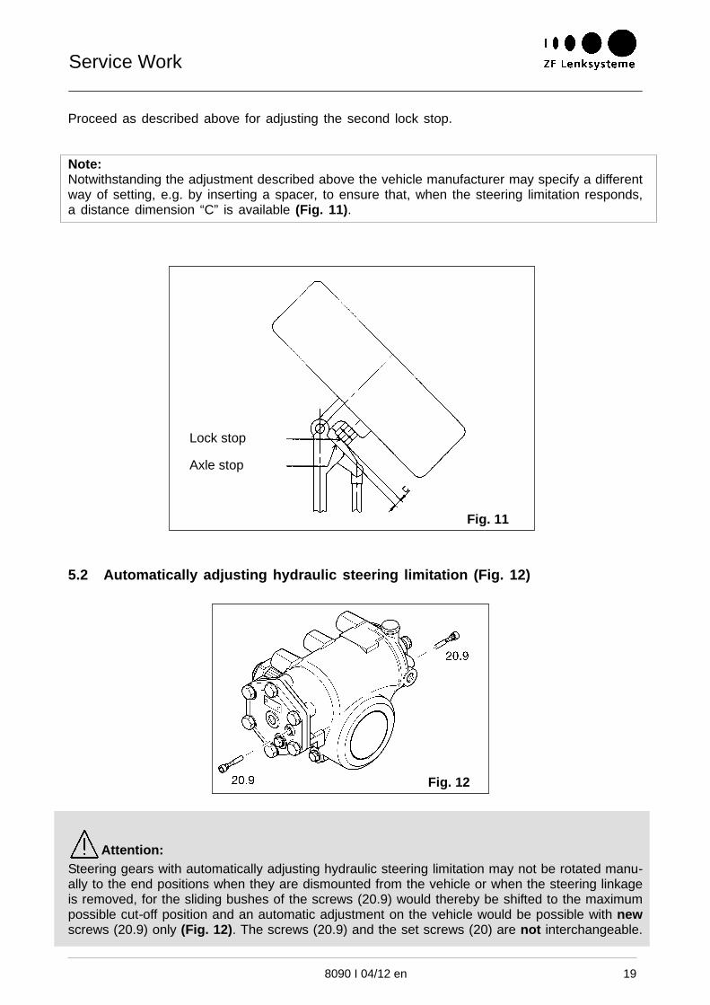
Lock stop
Axle stop
Fig. 12
8090 I 04/12 en 19
Proceed as described above for adjusting the second lock stop.
Note:Notwithstanding the adjustment described above the vehicle manufacturer may specify a differentway of setting, e.g. by inserting a spacer, to ensure that, when the steering limitation responds,a distance dimension “C” is available (Fig. 11).
5.2 Automatically adjusting hydraulic steering limitation (Fig. 12)
Attention:Steering gears with automatically adjusting hydraulic steering limitation may not be rotated manu-ally to the end positions when they are dismounted from the vehicle or when the steering linkageis removed, for the sliding bushes of the screws (20.9) would thereby be shifted to the maximumpossible cut-off position and an automatic adjustment on the vehicle would be possible with newscrews (20.9) only (Fig. 12). The screws (20.9) and the set screws (20) are not interchangeable.

Service Work
Shifting
Axle stop
8090 I 04/12 en20
Fig. 13 Initial positionSliding bushes notyet adjusted
5.2.1 Mode of operation of the automatically adjusting hydraulic steering limitation
In the end positions the tappets of the valve pistons run up against the sliding bushes of thescrews (20.9) and open the steering limitation valves (U or T).
The opening of the steering limitation valves is determined by the position of the sliding busheson the screws (20.9).
5.2.2 Setting
Note:This setting (Fig. 14) can only be carried out after the installation of the steering gear on thevehicle. To enable the setting, the steering linkage and the axle stops must already be installedand set.
Fig. 14 Setting operationPositioning of thesliding bushes
� For vehicles with a rigid axle:
Relieve the steering gear by jacking it up (there must, however, still be a load on the steered axle)or place it on swivel plates. ¡
¡ see vehicle manufacturer’s instructions

Service Work
Cut-off point isdetermined bydrop arm travel
Axle stop
8090 I 04/12 en 21
� For vehicles with independent wheel suspension:
Place the wheels on swivel plates.
� With or without hydraulic assistance, rotate the steering wheel forward to the maximum lockstop.
This will cause the piston to push the sliding bush on the screw (20.9) up to the requiredcut-off position (Fig. 15).
Note:During this setting operation the steering limitation valve is permanently open. Therefore, an in-creased effort is required to rotate the steering wheel further irrespective of whether hydraulicassistance is available or not.
Repeat the setting operation for the opposite direction of rotation.
Fig. 15Left-hand steering limitation valveopen, oil pressure greatly reduced
5.2.3 Correcting the drop arm travel
Increasing the drop arm travel:
Carry out the setting as described above.
Reducing the drop arm travel:
Fit new screws (20.9).
Attention:The sliding bushes may not be pulled back on the screws (20.9).
Tightening torque for screws (20.9): 12+3 Nm

Repairing External Leakages
Fig. 16depending on the version
8090 I 04/12 en22
IV. Repairing External Leakages
1 Valve insert (22) - pressure relief valveUnscrew the valve insert (22) from the housing (Fig. 16) and remove any remains from theO-ring. If the pressure does not meet the specified value or if there is a leakage replace thecomplete valve insert (22).Fit a new greased O-ring (23) to the valve insert (22) and screw it in again.Tightening torque: 30+10 Nm
2 Valve insert (32) - replenishment valveUnscrew the screw (30) and the valve insert (32).Tuck the valve insert (32) into the housing bore and remove any remains from the O-ring.Fit a new greased O-ring (31) to the screw (30) and screw it in again.Tightening torque: 30+10 Nm
3 Screws (20.9)Screw in new screws (20.9).Tightening torque: 12+3 NmFor the setting of the steering limitation refer to Chapter III., paragraph 5.
4 Collar nut (21 and 129)Screw in new collar nuts (21 and 129).Tightening torque: 20+10 NmFor the setting of the steering limitation refer to Chapter III., paragraph 5.
5 Screw plug (55)Unscrew the screw plug (55), fit a new sealing ring (54) to it and screw it in again.Tightening torque: 40 Nm (M16x1.5)
50 Nm (M18x1.5)6 Bleeder (57)
Screw in a new bleeder (57).Tightening torque: 30 Nm
Attention:With the exception of the work listed above, no further repair work may be done. Repair workexceeding the scope of the work mentioned above has to be carried out by a ZF After-SalesService Centre.

Removal and Reinstallation of the Steering Gear
Fig. 17
8090 I 04/12 en 23
V. Removal and Reinstallation of the Steering Gear
1 Removal
1.1 Thoroughly clean the steering gear and its immediate surroundings, in particular the lineconnections.
Drain the oil as described in Chapter III.
Write down the positions of the pressure and the return lines or mark them.
Unscrew the pressure and return lines.
Tightly close all oil pipes (risk of soiling the oil).
1.2 Check whether the marks on the sector shaft and on the drop arm coincide.
Note:If the marks are offset from each other, prior to fitting the drop arm inquire with the vehiclemanufacturer whether differing assembly instructions exist.
Unscrew the locking nut (50).
Pull off the drop arm, using Tool [5].
Attention:Heating up the drop arm or driving in a wedge between the housing and the drop arm orremoving the drop arm by means of hammer blows is not permitted as such action maycause changes to the material or internal damages to the steering gear.
1.3 In addition, for vehicles with an adjustable steering column:
� Adjust the driver’s workplace to the topmost position to relieve the ball track universal shaftas much as possible.
� With a suitable tool, for instance a ratchet belt, relieve the ball track universal shaft in sucha way that no thrust force can act in the direction of the steering gear any more.
When you use a ratchet belt, if possible feed the belt through the yoke interspaces (seearrows in Fig. 17). Stretch the belt so much that any damage to the sealing elements or tothe protective cap of the steering gear is excluded when the universal joints are shifting atthe moment the clamping screws are unscrewed.
1.4 Unscrew the universal joint or the elastic coupling betweenthe steering gear and the steering column or the separatelyinstalled angle drive.
Unscrew the mounting screws and remove the steeringgear.
Note:If a fitting bolt was used, write down its position.

Removal and Reinstallation of the Steering Gear
Fig. 18
8090 I 04/12 en24
2 Reinstallation
Attention:In order to guarantee a safe operation of the steering system maximum cleanliness is an absolutemust when reinstalling all the units that are part of the system.
Note:
To avoid malfunctions caused by foreign bodies or impurities in the oil circuit of the steering gearthe plugs in the line ports of the steering gear, the oil pump, the steering cylinder, the valves etc.should be removed only the very moment the lines are connected. As far as possible remove anyprotection sleeves only after reinstallation of the steering gear. Connecting lines and pipe unionsmust be cleaned and deburred thoroughly.
2.1 Rotate the steering wheel to the straight ahead driving position.
Clean the locating faces of the mounting bracket and the steering gear.
2.2 In addition, for vehicles with adjustable driver‘s workplace:
Using a suitable tool, for example a ratchet belt, constrict the ball track universal shaft untilthere is sufficient space available for installing the steering gear (Fig. 18).
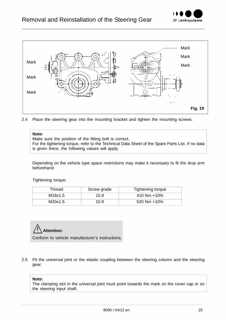
2.3 Determine the total number of steering wheel turns and divide it by two. Rotate the steeringgear the number of turns thus determined to reach mid-position. Then continue to rotate untilthe marks (see Fig. 19) on the steering input shaft, the protective cap and the housingcoincide.
Removal and Reinstallation of the Steering Gear
Mark
Mark
Mark
Mark
Mark
Mark
Fig. 19
8090 I 04/12 en 25
2.4 Place the steering gear into the mounting bracket and tighten the mounting screws.
Note:Make sure the position of the fitting bolt is correct.For the tightening torque, refer to the Technical Data Sheet of the Spare Parts List. If no datais given there, the following values will apply.
Depending on the vehicle type space restrictions may make it necessary to fit the drop armbeforehand.
Tightening torque:
Thread Screw grade Tightening torque
M18x1.5 10.9 410 Nm +10%
M20x1.5 10.9 520 Nm +10%
Attention:
Conform to vehicle manufacturer’s instructions.
2.5 Fit the universal joint or the elastic coupling between the steering column and the steeringgear.
Note:The clamping slot in the universal joint must point towards the mark on the cover cap or onthe steering input shaft.

Removal and Reinstallation of the Steering Gear
Fig. 20
at least 1.5
8090 I 04/12 en26
2.6 In addition, for vehicles with adjustable driver‘s workplace:
Put the universal joint on and take care not to damage the seal of the steering gear.
Tighten the clamping screw (M10x1.25), applying a torque of 48+5 Nm.
Relieve the tool, e.g. the ratchet belt, see Fig. 18, cautiously and remove it.
2.7 Move the steered wheels of the vehicle to the straight ahead driving position.
This position is reached when the steered wheels are aligned with the second pair of roadwheels, or parallel to it (to make sure, place a graduated ruler against the front and rearwheels).
2.8 Put the drop arm on the serration and make sure that the marks on the drop arm and onthe sector shaft coincide (see Fig. 19).
Screw the locking nut (50) on and tighten it, applying the torque specified below.
Note:For the tightening torque, refer to the Technical Data Sheet of the Spare Parts List. If no datais given there, the following values will apply.
Thread Serration Tightening torque Exception
M30x1.5 1 3/8“x36 250 Nm +10%M30x1.5 1 1/2“x36 300 Nm +10%M30x1.5 1 5/8“x36 330 Nm +10%M35x1.5 400 Nm +10%M42x1.5 500 Nm +10%M45x1.5 700 Nm +10% MAN/Neoplan:
850 Nm +10%
If the vehicle manufacturer specifies different values, manufacturer‘s values must be applied.
2.9 Peen the locking nut (50) as shown in Fig. 20. ¡
Put the drag links or the tie rods in place and tighten them. ¡
Forward steer the steering gear to the left until the stop is reached, and take the drag linksor the tie rods off.
¡ see vehicle manufacturer’s instructions

Removal and Reinstallation of the Steering Gear
8090 I 04/12 en 27
2.10 For versions with automatically adjusting steering limitation, in addition
Unscrew screws (20.9).
2.11 Try to rotate the steering wheel further to the left.
If no further steering motion to the left is possible the lock stop or the axle stop must bereadjusted.
Attention:
It must be ensured that the limitation of the steering angle takes place at the lock stops orthe axle stops steering angle limitation must not be done by the steering gear.
Mount the drag links or the tie rods again. ¡
Repeat the steering motion test to the right and, if required, readjust the lock stops or theaxle stops.
2.12 For versions with automatically adjusting steering limitation, in addition
Screw in again screws (20.9). Tightening torque: 12+3 Nm
2.13 Mount the drag links or the tie rods again. ¡
2.14 Connect the pressure and return lines between pump, steering gear and steering cylinderin accordance with the notes taken when the lines were removed.Fill the steering system with oil and bleed it.
See Chapter III.
2.15 Set the hydraulic steering limitation
See Chapter III.
2.16 Check the oil levelBefore pulling out the oil dipstick thoroughly clean the oil tank and its immediate surround-ings in order to prevent impurities from getting into the hydraulic fluid.
Attention:Too low an oil level may entail malfunctions which, in turn, may cause a power assistancefailure.
For vehicles equipped with a ZF Servocom RAS (rear axle steering system), inaddition:Check the oil level in the straight ahead driving position.If the oil level is above the top mark there may be a leakage in the master cylinder ofthe ZF Servocom RAS.
¡ see vehicle manufacturer’s instructions

Spezialwerkzeuge
8090 I 04/12 en28
VI. Special Tools
Note:The tools described below are universal tools. It may therefore be possible that special tools rec-ommended by the vehicle manufacturer become necessary for particular applications.
Ordering number
Tool [1]ZF Servotest 100
7418 798 100
Tool [2]Scale with pointer 7418 798 452
Tool [3]Thrust pad 7418 798 556
Tool [4] 1, offExpanding device 7418 798 653(2 of these are required)
Tool [5]Extracting device 7418 798 219

Trouble Shooting
8090 I 04/12 en 29
VII. Trouble Shooting
1 Tracing of failures in the steering system and checking of the hydraulicfunctions
1.1 Checking the steering input shaft bearing arrangement in the steering column for play
By swaying (jerking) the steering wheel sideways check whether there is any play.
If there is any, replace or repair the steering column/the bearing.
1.2 Checking the universal joint, the telescopic shaft and the angle drive for angular playor stiff operation
If any play (which can be identified by the noticeable rattling noise occurring when the steer-ing wheel is rotated forward and backward) or stiff operation is ascertained, replace thedefective components.
1.3 Checking for leakproofness
� Start the engine
� Check whether all screwed connections, pipe lines and sealing elements of the entire steer-ing system (angle drive, steering gear, pump and steering cylinder) are tight.
� Check all hoses, protective caps, bellows and pipe lines for possible scuff marks and crackscaused by embrittlement.
� Stop the engine.
Attention:When hose lines with externally visible damages such as cracks have to be replaced, make sureonly spare parts are used that are pressure tested and released by the vehicle manufacturer.

Trouble Shooting
Mark
Mark
Mark
Mark
Mark
Mark
Fig. 21
8090 I 04/12 en30
1.4 Checking the straight ahead driving positions of steering gear and vehicle
Attention:Steering gears equipped with an automatically adjusting hydraulic steering limitation must not berotated to the end positions if the steering linkage was removed previously.
� Vehicles with independent wheel suspension:
Place the wheels of the steered axle on swivel plates.
� Vehicles with a rigid axle:
Jack up the steered axle.¡
� Determine the total number of steering wheel turns and divide it by two. Rotate the steeringgear the number of turns thus determined to reach mid-position. Then continue to rotate untilthe marks (see Fig. 21) coincide.
Now turn the steered wheels to the straight ahead driving position.
Corrections can be made by screwing the ball joints on the drag links further in or out.
Attention:If the position of the steering wheel is incorrect or if the length of the steering linkage has to becorrected, it may well be that the cause of such non-conformity must be sought in a precedingaccident-like event. We therefore recommend to check whether the serration on the sector shaft(30) is twisted (to do so, remove the drop arm), whether the steering input shaft is installed in atwisted position and whether some or all further transmission elements are bent or have cracks.In addition check the play as described in Chapter III., paragraph 3. Components with deforma-tions may not be re-bent to shape but must be replaced.
For versions with automatically adjusting steering limitation, in addition:
Fit new screws (20.9) and readjust the steering limitation if required (for this purpose see ChapterIII., para. 5).
¡ see vehicle manufacturer’s instructions

Trouble Shooting
Fig. 21
8090 I 04/12 en 31
1.5 Checking the belt tension of the pump driveCheck the tension of the drive belt. ¡
The drive belt must transmit the power without any slippage even at pump maximum pressure.
1.6 Checking the hydraulic operation of the ZF pump and the ZF steering gear
1.6.1 Installing Tool [1] (ZF Servotest)
1 Pump2 Oil tank3 Pressure line4 Suction line5 Return line6 ZF Servotest
Install Tool [1] (ZF Servotest) in such a way that the displays are visible from the driver’s seat (Fig.22).
Check the oil level and bleed the steering system - see Chapter III.
Test temperature: 50±10°C
1.6.2 Checking the maximum pressure of the ZF pump
Attention:Admit maximum pressure for a short time only (10 seconds maximum) to avoid any excessiveheating-up of the inner parts of the pump and, in consequence, a premature wear of these parts.While checking, have the engine run at idling speed, only. Any increase in engine speed willimmediately cause the system pressure to soar, and in this case there is a risk of damages to thepressure line/pump.
Read the maximum permissible pressure from the type plate of the ZF steering gear/the ZF pump.
Open the shut-off valve and the pressure relief valve of Tool [1] and start the engine.
Close the shut-off valve and, with the help of the pressure relief valve, set Tool [1] in a wayexcluding any damage to the steering system during the subsequent tests.
Setting value: maximum pressure of the steering system (incl. upper tolerance) + 20 bar
¡ see vehicle manufacturer’s instructions

Trouble Shooting
8090 I 04/12 en32
Open the shut-off valve.
While watching the pressure gauge of Tool [1] slowly close the shut-off valve until the maximumpressure indicated for the pump is reached.
Specified value: maximum pressure, see type plate, +10 %
Open the shut-off valve.
If maximum pressure is not reached during this measurement the pump must be replaced orrepaired.
1.6.3 Checking the flow rate of the ZF pump
Note:For the specified values for flow rate, test pressure and test speed please refer to the TechnicalData Sheet of the Spare Parts List. For details about designations and the handling of Tool [1] (ZFServotest 100), please refer to the separate Operating Manual of the ZF Servotest 100.
� Checking the controlled flow rate
Raise the engine speed and continue to do so until the flow rate of the ZF pump remains constantdespite a further increase in speed. This will usually happen at approx. 1300 r.p.m.
The ZF pump is now in the flow control range.
Specified value: see Technical Data Sheet of Spare Parts List
� Checking the minimum flow rate
For the test pressure and the specified value for the minimum flow rate refer to the Technical DataSheet of the Spare Parts List.
At engine idling speed progressively close the shut-off valve until the specified test pressure forthe pump version is present.
Read the flow rate.
Make sure the engine speed / pump speed ratio is correct.
Specified value: see Technical Data Sheet of Spare Parts List

Trouble Shooting
8090 I 04/12 en 33
1.6.4 Checking the hydraulic steering limitation
1.6.4.1 Mechanically adjustable hydraulic steering limitation
� Vehicles with a rigid axle:
Jack up the steered axle. ¡
� Vehicles with independent wheel suspension:
Place the wheels of the steered axle on swivel plates.
� Rotate the steering wheel clockwise at a power of 100...200 N8. When the axle stop or thelock stop is reached, continue to rotate the steering wheel until a positive stop is reached.
In this position read the pressure at the pressure gauge:
Specified values: Steering systems up to 16 dm3/min: 40...50 bar
up to 20 dm3/min: 50...60 bar
in excess of 20 dm3/min: 70...80 bar
Repeat the test in the other direction of rotation.
For the setting of the steering limitation refer to Chapter III., paragraph 5.
1.6.4.2Automatically adjusting hydraulic steering limitation
Check as described in para. 1.6.4.1.
If there is no space left at the lock stop components or if the oil pressure does not drop to thespecified value, fit new screws (20.9) and readjust the steering limitation as described in ChapterIII., para. 5.
Specified values:Steering systems up to 16 dm3/min: 40...50 bar
up to 20 dm3/min: 50...60 bar
in excess of 20 dm3/min: 70...80 bar
If there is too much clearance at the lock stop components or if the oil pressure does not dropto the specified value, readjust the steering limitation as described in Chapter III., para. 5.
Repeat the test in the opposite direction of rotation.
¡ see vehicle manufacturer’s instructions
Trouble Shooting
Fig. 23
8090 I 04/12 en34
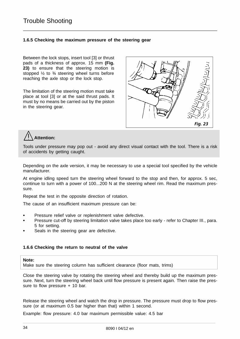
1.6.5 Checking the maximum pressure of the steering gear
Between the lock stops, insert tool [3] or thrustpads of a thickness of approx. 15 mm (Fig.23) to ensure that the steering motion isstopped ½ to ¾ steering wheel turns beforereaching the axle stop or the lock stop.
The limitation of the steering motion must takeplace at tool [3] or at the said thrust pads. Itmust by no means be carried out by the pistonin the steering gear.
Attention:
Tools under pressure may pop out - avoid any direct visual contact with the tool. There is a riskof accidents by getting caught.
Depending on the axle version, it may be necessary to use a special tool specified by the vehiclemanufacturer.
At engine idling speed turn the steering wheel forward to the stop and then, for approx. 5 sec,continue to turn with a power of 100...200 N at the steering wheel rim. Read the maximum pres-sure.
Repeat the test in the opposite direction of rotation.
The cause of an insufficient maximum pressure can be:
� Pressure relief valve or replenishment valve defective.� Pressure cut-off by steering limitation valve takes place too early - refer to Chapter III., para.
5 for setting.� Seals in the steering gear are defective.
1.6.6 Checking the return to neutral of the valve
Note:Make sure the steering column has sufficient clearance (floor mats, trims)
Close the steering valve by rotating the steering wheel and thereby build up the maximum pres-sure. Next, turn the steering wheel back until flow pressure is present again. Then raise the pres-sure to flow pressure + 10 bar.
Release the steering wheel and watch the drop in pressure. The pressure must drop to flow pres-sure (or at maximum 0.5 bar higher than that) within 1 second.
Example: flow pressure: 4.0 bar maximum permissible value: 4.5 bar

Trouble Shooting
Fig. 24
Tool [4]
Fig. 25
8090 I 04/12 en 35
1.6.7 Checking the steering gear for play
Attention:Do not allow higher pressures than those indi-cated below to act upon the tools and thewheel rim to avoid the risk of damages to therim.
Prerequisite for the test below:The transmission parts between the steeringwheel and the road wheel must be free fromplay.� Versions with leaf spring:Lock the left-hand front wheel (the right-handfront wheel if the vehicle is right-hand driven)in the straight ahead driving position by instal-ling tool [4] between the wheel rim (rear andfront) and the front leaf spring (Fig. 24).
� Versions with independent wheel suspension:Lock the left-hand front wheel (the right-hand front wheel if the vehicle is right-hand driven) asspecified by the vehicle manufacturer.
� Place Tool [2] onto the steering wheel and fasten the pointer to the dashboard or to thewindscreen (Fig. 25).
Raise the engine speed to approx. 1,000r.p.m.
Read the flow pressure at Tool [1] (ZF Servo-test).
Rotate the steering wheel to the left until 1 barabove flow pressure is indicated.
While doing so, read the scale value on Tool[2].
Rotate the steering wheel to the right until 1bar above flow pressure is indicated.
Read the scale value on Tool [2].
Calculate the total distance covered.
Specified value: 50 mm maximum (for a steer-ing wheel with Ø 500 mm)
For versions with angle drive:
Specified value: 55 mm maximum (for a steer-ing wheel with Ø 500 mm)
If the maximum value is exceeded, check the steering column for play and, if required, repair orreplace the steering gear.
Remove Tool [1] (ZF Servotest).
Check the oil level and bleed the steering system as described in Chapter III.

Trouble Shooting
8090 I 04/12 en36
2 Trouble shooting guide
Trouble Cause Remedial action
Noise There is air in the oil
Oil level is too low
Bleed the steering system ¢
Top up with oilPump is defective Repair ©
Replace ©Steering gear is defective Repair ©
Replace ©Oil used is not suitable Use an approved oil ¡Components of steering systemnot tuned correctly to each other
Re-tune the steering systemcomponents
Hoses/lines not laid/fastenedcorrectly
Correct fastening/laying ofhoses/lines ¡
Stiff operation to either side Oil level is too low Remedy the leakage
Top up with oil ¢Steering system is sucking in air
(suction area)
Remedy the leakage
Top up with oil ¢
Bleed the steering system £
Stiff operation of
universal joints/steering column
Check
Replace ¡Oil filter is soiled Replace ¢Steering gear is defective Repair ©Steering gear is defective
Replace ©Pump is defective Repair©Pump is defective
Replace ©Oil used is not suitable Use an approved oil ¡Steered axle load is too high Reduce the steered axle load ¡Oil temperature is too high Reduce the steered axle load ¡
Stiff operation to one side Incorrect setting of
steering limitation
Correct setting ¢
Steering gear defective Repair ©
Replace ©Stiff operation during
quick steering motions
Steering system is sucking in air
(suction area)
Remedy the leakageTop up with oil
Bleed the steering system ¢
Steering gear is defective Repair ©
Replace ©Pump is defective, or wrong ver-sion used
Replace the pump ©
¡ see vehicle manufacturer’s instructions© Ask ZF After Sales Service Centre for help¢ See Chapter III.

Trouble Shooting
8090 I 04/12 en 37
Trouble Cause Remedial action
Self-aligning inhibited Stiff operation of axle/axle guideelements
Repair ¡
Twisted installation of steeringgear/Steering column
Correct twisted
installation ¡
Stiff operation of steering column Remedy stiff
operation ¡
Flow pressure too high Install correct line cross section
Route the line correctly
check whether an orifice wasinstalled where no one may befittedb) install correct orificewhere a wrong one was fitted¡
Steering gear is defective Repair ©
Replace ©Replace ©
Impossible to drive exactly
straight ahead
Oil level is too low Remedy the leakage
Top up with oil ¢Top up with oil ¢
Bleed the steering system ¢Bleed the steering system ¢
Axle/axle guide elements/steer-ing column
not free from play
Check ¡
Replace ¡
Steering gear not free from play Check ¢
Replace ©
¡ See vehicle manufacturer’s instructions
© Ask ZF After Sales Service Centre for help
¢ See Chapter III.

Key to Numbers in Figures and Exploded View
depending on the version
8090 I 04/12 en38
IX. Key to numbers in figures and exploded view
20 Set screw/screw 20.1 O-Ring
20.9 Screw 21 Collar nut
22 Valve insert 23 O-Ring
30 Screw 31 O-Ring
32 Valve insert 54 Sealing ring
55 Screw plug 57 Bleeder

Maintenance Report forZF Servocom Steering GearsOriginal for duplicating
8090 I 04/12 en 39
Customer: Steering gear version:. . . . . . . . . . . . . . . . . . . . . . . . . . . . . . . . . . . . . . . . . . . . . . . . . . . . . . .
Vehicle manufacturer: Pump manufacturer:. . . . . . . . . . . . . . . . . . . . . . . . . . . . . . . . . . . . . . . . . . . . . .
Vehicle type (or model): Pump version:. . . . . . . . . . . . . . . . . . . . . . . . . . . . . . . . . . . . . . . . . . . . . . . . .
Mileage: Emergency steering pump:. . . . . . . . . . . . . . . . . . . . . . . . . . . . . . . . . . . . . . . . . . . . . . . . . . . .
1 Has vehicle been test driven? � Yes � No
Complaints: . . . . . . . . . . . . . . . . . . . . . . . . . . . . . . . . . . . . . . . . . . . . . . . . . . . . . . . . . . . . . . .
2 Tested or checked for external leakproofness/damages? � Yes � No
Complaints: . . . . . . . . . . . . . . . . . . . . . . . . . . . . . . . . . . . . . . . . . . . . . . . . . . . . . . . . . . . . . . . . . . . . . .
3 Oil level checked? � Yes � No
Remarks: . . . . . . . . . . . . . . . . . . . . . . . . . . . . . . . . . . . . . . . . . . . . . . . . . . . . . . . . . . . . . . . . . . . . . . . .
. . . . . . . . . . . . . . . . . . . . . . . . . . . . . . . . . . . . . . . . . . . . . . . . . . . . . . . . . . . . . . . . . . . . . . . . .
Inspected by: Date:. . . . . . . . . . . . . . . . . . . . . . . . . . . . . . . . . . . . . . . .

Inspection Report forZF Servocom Steering GearsOriginal for duplicating
8090 I 04/12 en40
Customer: Steering gear version:. . . . . . . . . . . . . . . . . . . . . . . . . . . . . . . . . . . . . . . . . . . . . . . . . . . . . . .
Vehicle manufacturer: Pump manufacturer:. . . . . . . . . . . . . . . . . . . . . . . . . . . . . . . . . . . . . . . . . . . . . .
Vehicle type (or model): Pump version:. . . . . . . . . . . . . . . . . . . . . . . . . . . . . . . . . . . . . . . . . . . . . . . . .
Mileage: Emergency steering pump:. . . . . . . . . . . . . . . . . . . . . . . . . . . . . . . . . . . . . . . . . . . . . . . . . . . .
1 Inspection intervals (see Chapter III.)
2 Has vehicle been test driven? � Yes � No
Complaints: . . . . . . . . . . . . . . . . . . . . . . . . . . . . . . . . . . . . . . . . . . . . . . . . . . . . . . . . . . . . . . .
3 Visual inspection made? � Yes � No
Complaints: . . . . . . . . . . . . . . . . . . . . . . . . . . . . . . . . . . . . . . . . . . . . . . . . . . . . . . . . . . . . . . .
4 Oil filter replaced? � Yes � No
5 Steering gear checked for play? � Yes � No
Specified value: Measured value: mm. . . . .
max. 50 mm
max. 55 mm (for versions with angle drive)
6 SP tests carried out? � Yes � No
Remarks: . . . . . . . . . . . . . . . . . . . . . . . . . . . . . . . . . . . . . . . . . . . . . . . . . . . . . . . . . . . . . . . . . . . . . . . . . . . . .
Inspected by: Date:. . . . . . . . . . . . . . . . . . . . . . . . . . . . . . . . . . . . . . . .
Trouble Shooting Report forZF Servocom Steering GearsOriginal for duplicating
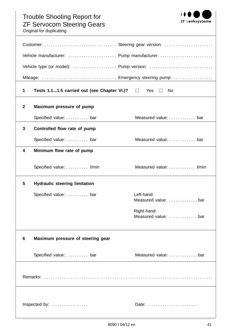
8090 I 04/12 en 41
Customer: Steering gear version:. . . . . . . . . . . . . . . . . . . . . . . . . . . . . . . . . . . . . . . . . . . . . . . . . . . . . . .
Vehicle manufacturer: Pump manufacturer:. . . . . . . . . . . . . . . . . . . . . . . . . . . . . . . . . . . . . . . . . . . . . .
Vehicle type (or model): Pump version:. . . . . . . . . . . . . . . . . . . . . . . . . . . . . . . . . . . . . . . . . . . . . . . . .
Mileage: Emergency steering pump:. . . . . . . . . . . . . . . . . . . . . . . . . . . . . . . . . . . . . . . . . . . . . . . . . . . .
1 Tests 1.1...1.5 carried out (see Chapter VI.)? � Yes � No
2 Maximum pressure of pump
Specified value: bar Measured value: bar. . . . . . . . . . . . . . . . . . . . . .
3 Controlled flow rate of pump
Specified value: bar Measured value: bar. . . . . . . . . . . . . . . . . . . . . .
4 Minimum flow rate of pump
Specified value: l/min Measured value: l/min. . . . . . . . . . . . . . . . . . . . . .
5 Hydraulic steering limitation
Specified value: bar Left-hand:. . . . . . . . . .Measured value: bar. . . . . . . . . . . . .
Right-hand:Measured value: bar. . . . . . . . . . . . .
6 Maximum pressure of steering gear
Specified value: bar Measured value: bar. . . . . . . . . . . . . . . . . . . . . . .
Remarks: . . . . . . . . . . . . . . . . . . . . . . . . . . . . . . . . . . . . . . . . . . . . . . . . . . . . . . . . . . . . . . . . . . . . . . . . . . . . .
Inspected by: Date:. . . . . . . . . . . . . . . . . . . . . . . . . . . . . . . . . . . . . . . .