b006 pusd - trex · web viewthe training system will also support a single fbd for each of the...
TRANSCRIPT

DiSTI Doc. # PGM-STRK4A-0009 Stryker MTS Phase IVaRevision: 3. Jun 20, 2018 CDRL B006
PROGRAM-UNIQUE SPECIFICATION DOCUMENTFOR THE
STRYKER MAINTENANCE TRAINING SYSTEM (MTS) PHASE IVA PROGRAM
DESK TOP TRAINER (DTT)
CDRL B006-00320 June 2018
Contract Number: W900KK-09-D-0562 / 0005
Submitted To:
U.S. Army Program Executive Office forSimulation, Training, and Instrumentation (PEO STRI)
12350 Research ParkwayOrlando, FL 32826-3276
Prepared By:
The DiSTI Corporation11301 Corporate Blvd. Suite 100
Orlando, FL 32817
DISTRIBUTION STATEMENT D. DISTRIBUTION AUTHORIZED TO THE DEPARTMENT OF DEFENSE AND U.S. DOD CONTRACTORS ONLY DUE TO CRITICAL TECHNOLOGY; EFFECTIVE FEBRUARY 26 2016. OTHER REQUESTS FOR THIS
DOCUMENT SHALL BE REFERRED TO US ARMY, PEO STRI, ATTN: SFAE-STRI-TRADE-GCTT, 12350 RESEARCH PARKWAY, ORLANDO, FL 32826
WARNING: THIS DOCUMENT CONTAINS TECHNICAL DATA WHOSE EXPORT IS RESTRICTED BY THE ARMS-EXPORT CONTROL ACT (TITLE 22, U.S.C., SECTION 2751 ET. SEQ.) OR THE EXPORT ADMINISTRATION ACT OF 1979 AS
AMENDED, TITLE 50, U.S.C., APP 2401 ET. SEQ. VIOLATION OF THESE EXPORT LAWS ARE SUBJECT TO SEVERE CRIMINAL PENALTIES. DISSEMINATE IN ACCORDANCE WITH PROVISIONS OF DOD DIRECTIVE 5230.25.
DESTRUCTION NOTICE: UNCLASSIFIED, LIMITED DOCUMENT, DESTROY BY ANY METHOD THAT WILL PREVENT DISCLOSURE OF CONTENTS OR RECONSTRUCTION OF THIS DOCUMENT.

DiSTI Doc. # PGM-STRK4A-0009 Stryker MTS Phase IVaRevision: 3. Jun 20, 2018 CDRL B006
REVISION HISTORY
Revision Reason for Change Submit Date
1 Initial Release Phase IVa 3/22/2017
2 Update for Phase IVa Software Release 2 TRR 4/9/2018
3 Final Release Phase IVa 6/20/2018
Use or disclosure of this data is subject to the restriction on the title page of this document.
i

DiSTI Doc. # PGM-STRK4A-0009 Stryker MTS Phase IVaRevision: 3. Jun 20, 2018 CDRL B006
1 SCOPE..........................................................................................................................5
1.1 IDENTIFICATION............................................................................................................51.2 SYSTEM OVERVIEW......................................................................................................51.3 DOCUMENT OVERVIEW.................................................................................................5
2 REFERENCED DOCUMENTS.....................................................................................7
2.1 GOVERNMENT DOCUMENTS..........................................................................................72.1.1 SPECIFICATIONS, STANDARDS, AND HANDBOOKS.........................................................72.1.2 OTHER GOVERNMENT DOCUMENTS, DRAWINGS, AND PUBLICATIONS............................72.2 NON-GOVERNMENT PUBLICATIONS...............................................................................7
3 REQUIREMENTS.........................................................................................................8
3.1 REQUIRED MODES.......................................................................................................83.1.1 LESSON SELECTION..................................................................................................83.1.2 LECTURE..................................................................................................................83.1.3 DEMONSTRATION......................................................................................................83.1.4 TRAINING..................................................................................................................93.1.5 DIAGNOSTICS............................................................................................................93.2 SYSTEM CAPABILITY REQUIREMENTS............................................................................93.2.1 FIDELITY REQUIREMENTS........................................................................................103.2.2 TRAINING EXECUTION MODES..................................................................................163.2.3 INSTRUCTOR CAPABILITIES......................................................................................163.2.4 VISUAL AND AURAL CUES REQUIREMENTS...............................................................193.2.5 CAUTIONS AND WARNINGS REQUIREMENTS..............................................................213.2.6 TEST, MEASUREMENT, AND DIAGNOSTIC EQUIPMENT (TMDE) REQUIREMENTS.........213.2.7 DAILY OPERATIONAL READINESS FOR TRAINING REQUIREMENTS...............................223.2.8 DEVICE SPECIFIC REQUIREMENTS............................................................................233.2.9 TRAINING MANAGEMENT SYSTEM (TMS)..................................................................303.2.10 SOFTWARE SUPPORT ENVIRONMENT (SSE)...........................................................333.3 SYSTEM EXTERNAL INTERFACE REQUIREMENTS..........................................................333.4 SYSTEM INTERNAL INTERFACE REQUIREMENTS...........................................................343.5 SYSTEM INTERNAL DATA REQUIREMENTS...................................................................343.6 SAFETY REQUIREMENTS.............................................................................................343.6.1 HAZARDOUS MATERIALS..........................................................................................343.6.2 FIRE PROTECTION...................................................................................................343.6.3 POWER OFF............................................................................................................343.6.4 EMERGENCY OFF SWITCHES...................................................................................353.6.5 OVERLOAD PROTECTION.........................................................................................353.6.6 POWER FAILURE PROVISIONS..................................................................................35
Use or disclosure of this data is subject to the restriction on the title page of this document.
ii

DiSTI Doc. # PGM-STRK4A-0009 Stryker MTS Phase IVaRevision: 3. Jun 20, 2018 CDRL B006
3.6.7 GUARDS AND INTERLOCKS.......................................................................................353.7 SECURITY AND PRIVACY REQUIREMENTS....................................................................353.8 SYSTEM ENVIRONMENT REQUIREMENTS......................................................................363.9 COMPUTER RESOURCE REQUIREMENTS......................................................................363.9.1 COMPUTER HARDWARE REQUIREMENTS..................................................................363.9.2 COMPUTER HARDWARE RESOURCE UTILIZATION REQUIREMENTS..............................363.9.3 COMPUTER SOFTWARE REQUIREMENTS...................................................................373.9.4 COMPUTER COMMUNICATIONS REQUIREMENTS........................................................373.10 DESIGN AND CONSTRUCTION CONSTRAINTS..............................................................373.10.1 SOFTWARE DESIGN CONSTRAINTS.........................................................................383.10.2 HARDWARE DESIGN CONSTRAINTS........................................................................383.11 PERSONNEL-RELATED REQUIREMENTS.....................................................................383.12 LOGISTICS-RELATED REQUIREMENTS.......................................................................393.12.1 NAMEPLATES AND PRODUCT MARKINGS.................................................................393.12.2 ACCESSIBILITY......................................................................................................403.12.3 PARTS..................................................................................................................413.12.4 ASSEMBLIES.........................................................................................................413.12.5 COVERS, PANELS, AND DOORS...............................................................................413.12.6 HANDLES..............................................................................................................413.12.7 MODULAR ASSEMBLIES..........................................................................................42
4 QUALIFICATION PROVISIONS.................................................................................43
5 NOTES........................................................................................................................44
5.1 ABBREVIATIONS AND ACRONYMS...............................................................................44
APPENDIX A AUTOMOTIVE TROUBLESHOOTING...................................................47
APPENDIX B AUTOMOTIVE MAINTENANCE.............................................................77
APPENDIX C VEHICLE OPERATIONS........................................................................85
APPENDIX D COMPONENTS.......................................................................................87
APPENDIX E BUTTON TASKS..................................................................................152
APPENDIX F RWS TROUBLESHOOTING.................................................................189
APPENDIX G RWS MAINTENANCE..........................................................................195
Use or disclosure of this data is subject to the restriction on the title page of this document.
iii

DiSTI Doc. # PGM-STRK4A-0009 Stryker MTS Phase IVaRevision: 3. Jun 20, 2018 CDRL B006
APPENDIX H ATGM TROUBLESHOOTING..............................................................197
APPENDIX I ATGM MAINTENANCE..........................................................................208
APPENDIX J FSV TROUBLESHOOTING..................................................................210
APPENDIX K FSV MAINTENANCE............................................................................213
APPENDIX L MCV TROUBLESHOOTING.................................................................214
APPENDIX M MCV MAINTENANCE..........................................................................215
APPENDIX N MGS TROUBLESHOOTING.................................................................216
APPENDIX O MGS MAINTENANCE..........................................................................237
APPENDIX P IETM FILTER OPTIONS.......................................................................240
Use or disclosure of this data is subject to the restriction on the title page of this document.
iv

DiSTI Doc. # PGM-STRK4A-0009 Stryker MTS Phase IVaRevision: 3. Jun 20, 2018 CDRL B006
1 SCOPEThis Specification defines the requirements for the Stryker Maintenance Training System (MTS) Phase IV Diagnostic/Troubleshooting Trainer (DTT) and the methods to be used to ensure that each requirement has been met. This specification expands on the Phase IV fielded trainer by incorporating a Phase IVa update with 3-D graphics for additional Stryker maintenance and troubleshooting procedures and the addition of software usability enhancements.
1.1 IdentificationThe Phase IV DTT Stryker Maintenance Trainer is also referred to as “the trainer” or “the training device” within this document. The trainer provides maintenance training capability for the Army’s 91S Military Occupational Specialty (MOS). This capability supports familiarization, institutional and unit training. The intent is to provide training for maintenance personnel in system operation, symptom verification, troubleshooting, fault isolation, adjustment, servicing, and removal/replacement of Line Replaceable Units (LRUs).
1.2 System OverviewThe Stryker vehicle is a single hull, eight-wheel vehicle delivered in multiple versions: including the Infantry Carrier Vehicle (ICV), Engineering Support Vehicle (ESV), Anti-Tank Guided Missile Vehicle (ATGM), Fire Support Vehicle (FSV), Mortar Carrier Vehicle (MC) and Mobile Gun System (MGS). The Phase IV DTT Stryker MTS is designed to teach the soldier troubleshooting tasks and remove and replace tasks for the 91S military occupational specialties (MOS). The Phase IV DTT is capable of training critical tasks contained in this MOS on each vehicle variant. This document presents the Program-Unique Requirements of the Phase IV DTT and the associated Training Management System (TMS). The Phase IV DTT trainer is a completely virtual system utilizing 3-D graphics. Navigation and interaction with the trainer is through mouse inputs.
1.3 Document OverviewThis document describes the system requirements of the Phase IV DTT. Where a conflict with this specification and any documentation referenced by this specification regarding or applying to the Stryker MTS occurs, this specification shall take precedence. There is no classified material used in the generation or execution of this software.
Appendix A - Automotive Troubleshooting Training Task List (TTL) includes a list of the supported Automotive Troubleshooting training tasks for the Phase IV DTT.
Appendix B - Automotive Maintenance TTL includes a list of the supported Automotive Maintenance training tasks for the Phase IV DTT.
Appendix C – Vehicle Operations List includes a list of supported operational tasks for the Phase IV DTT.
Appendix D - Components contains a list of the vehicle components supported by the Phase IV DTT. ( THIS LIST MUST BE EXPANDED BASED ON THE FINAL DESIGN )
Use or disclosure of this data is subject to the restriction on the title page of this document.
5

DiSTI Doc. # PGM-STRK4A-0009 Stryker MTS Phase IVaRevision: 3. Jun 20, 2018 CDRL B006
Appendix E Button Tasks contains a list of the button tasks (i.e., single action user tasks that accomplish multiple maintenance activities such as “Perform Road Test”) supported by the Phase IV DTT. (THIS LIST MUST BE EXPANDED BASED ON THE FINAL DESIGN)
Appendix F - RWS Troubleshooting TTL includes a list of the supported Troubleshooting tasks for the RWS.
Appendix G – RWS Maintenance TTL includes a list or the supported Maintenance tasks for the RWS.
Appendix H – ATGM Troubleshooting TTL includes a list of the supported Troubleshooting tasks for the ATGM.
Appendix I – ATGM Maintenance TTL includes a list or the supported Maintenance tasks for the ATGM.
Appendix J – FSV Troubleshotting TTL includes a list of the supported Troubleshooting tasks for the FSV.
Appendix K – FSV Maintenance TTL includes a list of the supported Maintenance tasks for the FSV.
Appendix L – MCV Troubleshooting TTL includes a list of the supported Troubleshooting tasks for the MCV.
Appendix M – MCV Troubleshooting TTL includes a list or the supported Maintenance tasks for the MCV.
Appendix N – MGS Troubleshooting TTL includes a list of the supported Troubleshooting tasks for the MGS
Appendix O – MGS Maintenance TTL includes a list of the supported Maintenance tasks for the MGS.
Appendix P – List of filter options applicable to the IETM for the MGS and IAV.
Use or disclosure of this data is subject to the restriction on the title page of this document.
6
DiSTI Doc. # PGM-STRK4A-0009 Stryker MTS Phase IVaRevision: 3. Jun 20, 2018 CDRL B006
2 REFERENCED DOCUMENTS2.1 Government Documents
2.1.1 Specifications, standards, and handbooks. The following specifications, standards, and handbooks form a part of this document to the extent specified herein. Unless otherwise specified, the issues of these documents are those cited in the solicitation or contract.
MIL-STD-130 Identification Marking of U.S. Military Property
(Copies of these documents are available from the Standardization Document Order Desk, 700 Robbins Avenue, Building 4D, Philadelphia, PA 19111-5094 or http://quicksearch.dla.mil/
2.1.2 Other Government documents, drawings, and publicationsStryker Phase IVa Requirements Traceability Matrix
EMSNG IETM Viewer Version 2.1.10
Interim Armored Vehicle (IAV) TM 9-2355-311-13&P dated 10 Dec 2015
Mobile Gun System (MGS) TM 9-2355-321-13&P dated 31 Oct 2013
2.2 Non-Government publications NFPA 101 Life Safety Code
NFPA 70 National Electrical Code
NFPA 72 National Fire Alarm Code
NFPA 780 Standard for the Installation of Lightning Protection Systems
ANSI Z535.4 Standard for Product Safety Signs and Labels
(Copies of these documents are available from the NFPA Catalog at www.nfpa.org or ANSI Standards Store www.ansi.org.)
Use or disclosure of this data is subject to the restriction on the title page of this document.
7

DiSTI Doc. # PGM-STRK4A-0009 Stryker MTS Phase IVaRevision: 3. Jun 20, 2018 CDRL B006
3 REQUIREMENTS3.1 Required ModesThe trainer will operate in or support various modes. The modes include Lesson Selection, Lecture, Demonstration, Training, and Diagnostics. The Lesson Selection and Diagnostics modes are operator selectable. The Lecture, Demonstration, and Training modes are a common mode of execution but differ in how the instructor makes use of that mode. The characteristics of these modes are addressed in the relative paragraphs of this section.
3.1.1 Lesson SelectionThe trainer shall provide the capability for the instructor to select a lesson. The Training Management System (TMS) maintains a library of lessons that can be selected for training. All lessons for the automotive, Remote Weapon Station (RWS), Anti-tank guided Missile (ATGM), Fire Support Vehicle (FSV), and Mortar Carrier (MC) shall follow Stryker Integrated Electronic Technical Manual (IETM) 9-2355-311-13&P dated 10 December 2015 using Electronic Maintenance System (EMS) Next Generation (NG) viewer v2.1.10 and all lessons for the Mobile Gun System (MGS) shall follow IETM 9-2355-321-13&P with release date of 31 October 2013. Filter options for each TM are defined in Appendix P. The filter options from Appendix P shall be pre-loaded but modifiable by the student. From the Instructor Operator Station (IOS), the instructor can select an appropriate lesson from that library to use for training. Refer to Section 3.2.3.1 Lesson Planning for further definition of the Lesson Planning/Selection capabilities of the trainer.
3.1.2 LectureThe DTT trainers provide a classroom environment where the instructor presents both normal and faulted system functionality. The IOS on the DTT shall allow the operator to optionally select displays for projection on two screens, supporting the instructor’s lecture with high fidelity references to actual vehicle systems and panels. IOS capability shall be provided to:
a. Select normal or faulted operation
b. Select the presentation method (equipment graphics, functional block diagrams, electrical schematics, IETM)
c. Control the lesson (refer to Section 3.2.3 Instructor Capabilities)
d. Project a large screen video display
3.1.3 DemonstrationThe trainers provide an environment where the instructor has the option to demonstrate both normal and faulted system functionality. IOS capability shall be provided to:
a. Select normal or faulted operation
b. Select the presentation method (equipment graphics, functional block diagrams, electrical schematics, IETM)
Use or disclosure of this data is subject to the restriction on the title page of this document.
8

DiSTI Doc. # PGM-STRK4A-0009 Stryker MTS Phase IVaRevision: 3. Jun 20, 2018 CDRL B006
c. Control the lesson (refer to Section 3.2.3 Instructor Capabilities)
3.1.4 TrainingIn this mode, the instructor sets up a scenario for students and observes their progress. A scenario is essentially a virtual representation of the steps required to perform a given Enabling Learning Objective (ELO). The use of the term “scenario” throughout this document is synonymous with an ELO. The trainer mode shall:
a. Support a classroom lockstep mode on the DTTs. In classroom lockstep mode, all of the students must complete the same step in a scenario before any student can move to the next step.
b. Support individual lockstep mode on the DTTs. In the individual lockstep mode, the student must perform all of the operations required by the IETM in the same order as that document describes. There is no interaction with other students.
c. Support knowledge based training by displaying the schematics or system diagram in sufficient detail to allow the student to demonstrate their understanding of the system operation.
d. Provide instructional features and controls to support the learning objectives and instructional tasks during trainer simulation operations. The student workstations simulate the vehicle and support operations of the maintainer.
The default vehicle variant selected on the IOS for an instructor or warrant officer shall be the ICV. The instructor, warrant officer and student shall be able to select any Stryker series variant that will be used for training when running in a Free Run mode. Execution of all training tasks is assumed to be ISA Standard Day. Refer to Section 3.2.2 Training Execution Modes for additional information on supported training modes.
3.1.5 DiagnosticsDuring the loading phase of the computational system, available diagnostics that require no interaction by the operator shall be executed. If all tests are passed, the simulator initialization shall proceed without operator intervention. If any of the diagnostic tests should fail, the simulator shall automatically enter the diagnostic mode. In addition, after the trainer has been initialized for simulation, the operator shall have the ability to enter the diagnostic mode and select from any of the available diagnostics and alignment procedures that have been provided with the COTS system.
3.2 System Capability RequirementsThe Stryker MTS is both a training device and a training management tool. The maintenance training systems shall provide a familiarization, institutional, unit training and skill level development capability for system operation, fault diagnosis, troubleshooting, adjustments, removal/replacement tasks required by the Stryker vehicle systems. A training management workstation, networked, but separate from the training system(s), shall be provided to allow management to retrieve, review, update, correct, delete, archive, and printout selected student performance (by name or ID number) or group performance data. Refer to the Section 3.2.9 Training Management
Use or disclosure of this data is subject to the restriction on the title page of this document.
9

DiSTI Doc. # PGM-STRK4A-0009 Stryker MTS Phase IVaRevision: 3. Jun 20, 2018 CDRL B006
System (TMS) section of this document for a complete listing of the reporting capabilities.
The appendices contain the Training Task List (TTL) listing the troubleshooting and maintenance tasks to be supported by the Phase IV DTT. The maintenance training systems shall provide training for the tasks defined in the TTL. The training system(s) shall provide a library of preprogrammed training scenarios to train the ELOs contained in the TTL. For the automotive related ELOs, the vehicle variant supported for Phase IV training shall be the ICV.
For these preprogrammed training scenarios, the fault symptoms shall be predetermined by the scenario content and shall not be alterable by the instructor. The training system(s) shall simulate faults that require the replacement of one or more LRUs to correct the symptoms, as dictated by the tasks identified in the TTL. Completion of the proper fault response sequence by the student shall cancel the fault symptoms in the simulation.
3.2.1 Fidelity RequirementsThe training system(s) shall train the functional application of the vehicle system through the student interface, providing those external stimuli and visual effects that prompt crewmember action/reaction. The training system(s) shall simulate to an appropriate level of fidelity the features, functions, and performance of the vehicle crew compartment. The vehicle systems to be simulated for required training shall include the following:
a. Remote Weapon Station
b. Anti-Tank Guided Missile (ATGM) System
c. Fire Support Vehicle (FSV) System
d. Mortar Carrier Vehicle (MCV) System
e. Mobile Gun System (MGS)
f. Power Pack
g. Engine
h. Transmission
i. Power Module
j. Pneumatic System
k. Fuel System
l. Exhaust System
m. Driveline
n. Suspension
o. Doors, Hatches and Grilles
p. Cooling Module
q. Central Tire Inflation System
Use or disclosure of this data is subject to the restriction on the title page of this document.
10

DiSTI Doc. # PGM-STRK4A-0009 Stryker MTS Phase IVaRevision: 3. Jun 20, 2018 CDRL B006
r. Pneumatic Brake System
s. Steering System
t. Electrical System
u. Height Management System
v. Climate Control
w. Automatic Fire Extinguisher System (AFES)
x. Hydraulic System
y. Winch Assembly
z. Lighting System
aa. Seating Assemblies
bb. Covers, Guards and Access Panels
cc. Monitoring and Warning Devices
The training system(s) shall simulate the actual vehicle with sufficient fidelity to adequately train students based on simulations of these vehicle systems. All simulated vehicle subsystems and components shall replicate the appearance, function, and application of actual vehicle components as 3-D graphics at the fidelity and level of detail necessary to train the tasks specified in this document. Where applicable, the audio-visual feedback shall replicate the vehicle equipment.
The user shall be given the capability to perform pre-defined ancillary tasks (e.g., road test) in a single action. These tasks are not the focus of the training, but may be required to be accomplished to complete the assigned task. A complete listing of these single action (i.e., Button Task) tasks can be found in the Appendix of this specification.
The TMS shall provide the capability to select Troubleshooting ELOs that do not require the student to perform detailed maintenance actions (i.e., Single Action LRU Replacements) on the DTTs, as dictated by the content of the TTL. Single Action LRU replacement shall account for all steps within a referenced Remove/Install Maintenance Task, including those steps that occur under the "Conditions" and "Follow-on" sections in the IETM for that Maintenance Task. Any LRU replacement that occurs under a Troubleshooting path in the TTL shall be performed as a Single Action LRU Replacement. Upon completion of a Single Action LRU Replacement, the state of the vehicle system models shall reflect any impact that would result from the execution of the Maintenance Task activities accounted for in the Single Action as described above. The resultant state of the execution of a Single Action LRU Replacement, or any Button Task, shall be achieved without presenting any of the transitory states (i.e., graphical transitions, aural cues, etc.) to the user.
To support the objectives of the tasks defined in the TTL, there are certain system parameters that have no impact on the success of achieving these objectives. Those parameters can assume to be constant with no impact on the value of training. The following is a list of such parameters:
Engine oil quantity shall always be at a constant value of full
Use or disclosure of this data is subject to the restriction on the title page of this document.
11

DiSTI Doc. # PGM-STRK4A-0009 Stryker MTS Phase IVaRevision: 3. Jun 20, 2018 CDRL B006
Hour Meter shall display a constant value of accumulated engine operating hours
Odometer shall display a constant value of accumulated distance in miles
Fuel tank quantity shall always be at a constant value of full, when not faulted or drained
The Battery Power Source will always be fully charged at a battery capacity of 100 ampere hours
Maintenance Support Device's (MSD) internal batteries shall have limitless power to support the MSD's normal operation
The training system(s) shall provide the controls, scenarios, visual cues, and sound cues required to train the ELOs identified in the TTL. Scenarios shall be unique, consisting of a set of training tasks to be completed. A scenario can be considered either preprogrammed or free-run. All preprogrammed scenarios for the Stryker MTS are identified in the TTL. A free-run scenario is not listed in the TTL; is not selectable by the instructor; and has no scoring capabilities but will alert the user when a hazardous condition has occurred. For each preprogrammed scenario, the instructor shall be provided with digitized text describing the tasks to be trained and grading criteria of the scenario. The activities of the student(s) and the status of the student’s training scenario shall be available to be displayed to the instructor on a monitor and remote Tablet.
3.2.1.1 RWS Fidelity RequirementsTo support RWS training of:
Troubleshooting TTL 24 and 25, and Maintenance TTL 14, the RWS simulation shall support operation, removal, installation and replacement of STORM LRF.
Maintenance TTL 13, the STORM LRF shall be capable of being adjusted while installed on the RWS.
Troubleshooting TTL 26, and Maintenance TTL 15, the RWS simulation shall support operation, removal, and installation of the Low Ammo Sensor.
Troubleshooting TTL 25 and 26, the RWS simulation shall support functionality of wiring harness W19 linking STORM LRF and Low Ammo Sensor to FCU.
Operational checkout following LRF Remove and Install, the RWS simulation shall support LCD functionality and MODE, L, and R buttons on LRF unit.
The Fire Control Unit (FCU) screen shall display range data from the STORM Laser Range Finder (LRF).
3.2.1.2 ATGM Fidelity RequirementsThe Monitoring and Warning subsystem's Video Display Terminal (VDT) shall support the fault codes as described in the ATGM TTL.
To support ATGM training of:
Troubleshooting TTL 1, AZIMUTH DRIVE TRAVERSES WITHOUT COMMAND; the symptom indicating that the platform traverses without command shall be
Use or disclosure of this data is subject to the restriction on the title page of this document.
12

DiSTI Doc. # PGM-STRK4A-0009 Stryker MTS Phase IVaRevision: 3. Jun 20, 2018 CDRL B006
modeled as the platform keeps rotating beyond 0 Degrees Azimuth and does not stop.
Troubleshooting TTL 12, GUNNER GYRO SWITCH FAILURE, FAULT CODE 0000 77B1, the last continuity check shall indicate continuity at the Gunner's Panel Assembly, J1, between Pins 14 and 79, indicating that the Gunner's Panel Assembly is internally damaged.
Troubleshooting TTL 13, GUNNER'S HANDLE GRIPS TEST FAILED, the symptom indicating that the GRIPS test Fails shall be modeled as the TOW unit will not slew based on gunner's handle input.
Troubleshooting TTLs 15 and 16, GUNNER'S PANEL ASSEMBLY (GPA) LAMP TEST FAILED, none of the lamps shall light during lamps test.
Troubleshooting TTLs 17, INCORRECT OR NO AZIMUTH INDICATION, none of the azimuth position indicators will illuminate when the azimuth position assembly is Failed in this path.
Troubleshooting TTLs 18 and 19, LASER RANGE FINDER RANGE (LRF) NOT DISPLAYED, the laser range finder range displayed on the gunner's display will initialize to zero and not update.
Troubleshooting TTL 20, LOADER CANNOT CONTROL PLATFORM, the last continuity check shall indicate continuity at the Loader's Panel Assembly, J1, between Pins 3 and 1, indicating that the Loader's Panel Assembly is internally damaged.
Troubleshooting TTLs 22 and 23, LOADER'S CONTROL PANEL LAMP TEST FAILED, none of the lamps shall light during lamps test.
Troubleshooting TTL 25, MAST LIMIT SWITCH FAILURE 1, FAULT CODE 0000 7740; the last continuity check shall indicate continuity at the Mast Lower Limit Switch's jack between Pins A and C, indicating that the switch is internally damaged.
Troubleshooting TTL 32, NO POWER AT PRIMARY WEAPON STATION, the symptom indicating that the ETS does not power up properly shall be that no LEDs on the Gunner's Control Panel illuminate in response to their respective switches.
Troubleshooting TTL 33, PLATFORM DEPRESSES/ELEVATES WITHOUT COMMAND, the symptom indicating that the platform depresses/elevates without command shall be modeled as the platform elevates to its stop without command and then halts.
Troubleshooting TTL 36, PLATFORM WILL NOT STABILIZE, the symptom indicating that the platform will not stabilize in elevation shall be modeled as the platform shall drift to maximum elevation and stay there.
Troubleshooting TTLs 41 and 42, TARGET ACQUISITION SYSTEM (TAS) COOLING FAN FAILURE, FAULT CODE 0000 7780, the indication that the TAS Cooling Fan is operating properly shall be modeled as an inspection of the fan.
Use or disclosure of this data is subject to the restriction on the title page of this document.
13

DiSTI Doc. # PGM-STRK4A-0009 Stryker MTS Phase IVaRevision: 3. Jun 20, 2018 CDRL B006
The Gunner's Display system alert "SELECT NVS BEFORE SELECTING TARGET TRACKER" shall be displayed if the TRK GATE switch is pressed in day TV mode. The Gunner's Display system alert "FOV CHANGE NOT ALLOWED DURING TARGET TRACKER USE" shall be displayed if the FOV button on the gunner's handle is pressed after target lock-on.
When CANCEL is selected from the Gunner's Display Main Menu, the menu shall disappear. When CANCEL is selected from the Gunner's Display BIT Menu, the BIT menu shall disappear. When TAS is selected from the Gunner's Display BIT Menu, the Gunner's Display shall display a system alert message that says "TAS ONLY BIT NOT VALID FOR ATGM VEHICLE." When TAS or MAINT is selected from the Gunner's Display BIT Menu, the student shall receive an indication that this action is not supported on the trainer.
The umbilical status shall indicate AGTM on the Gunner's Display.
The state indicator box on the Gunner's Display shall display the following:
DAY (alternate NIGHT)
WFOV (alternate NFOV)
LAST
When the ITAS is powered on from the Gunner's Control Panel, the Gunner's Display shall default to day TV, wide field of view, and surveillance mode following the completion of PBIT.
The gunner's handle buttons shall only be enabled when the gunner's handle is in its neutral position (i.e. the ETS is at rest).
3.2.1.3 FSV Fidelity RequirementsThe Driver’s Vision Enhancer (DVE) shall support power up and simulated video display.
To support FSV training of:
Troubleshooting TTL 16, TROUBLESHOOT CUPOLA INSTALLATION, the fault with the initial "Perform cupola installation functionality check" shall be modeled as the cupola drifts after releasing the force stick.
The Monitoring and Warning subsystem's Video Display Terminal shall display FS3 & DVE Video to support FSV TTL 17.
Troubleshooting TTL 17, VDT NOT DISPLAYING FS3 VIDEO; the simulation shall support swapping W35 P2/ VDT J2 with W501 P2/VDT J3.
3.2.1.4 MCV Fidelity RequirementsThere are no fidelity requirements specific to the MCV variant.
3.2.1.5 Mobile Gun System (MGS) Fidelity RequirementsTo support MGS training of:
Use or disclosure of this data is subject to the restriction on the title page of this document.
14

DiSTI Doc. # PGM-STRK4A-0009 Stryker MTS Phase IVaRevision: 3. Jun 20, 2018 CDRL B006
Ammunition Handling System with corresponding button task for each instance of ammunition handling in the MGS TTL.
Button task for the "Service Breechblock" task identified in MGS Troubleshooting TTL ID 33, BREECH OBSTRUCTION MESSAGE FLASHES ON CENTRAL CONTROL PANEL.
Ammunition Select Controls
Primary Armament
Secondary Armament
Commanders Weapon
Fighting Compartment
Target Acquisition and Firing Control System. The turret shall drift approximately 0.5 degrees per second in support of Fire Control System troubleshooting procedure "Main, Gun, Turret, or CMS Reticle Drifts" (TTLs 60 and 61).
Turret electrical Power
Turret Electronics
Turret Drive System. The "uncontrolled movement" in Turret Drive System troubleshooting procedure "Main Gun and/or Turret Has Uncontrolled Movement" (TTL 66) shall be approximately a 10 degree movement over 3 seconds repeatedly in each direction.
The training system button task capability shall provide a button task to perform MGS boresighting in the MGS TTL.
3.2.1.6 Automotive Fidelity RequirementsThe simulated Engine system shall support the ability to start and shut down the engine. Hydraulic pressure shall be represented as a function of engine RPM. The speed of the engine compartment fan shall be based on engine temperature.
The simulated Transmission system shall support the ability to shift into all gear ranges. Visual cues can be necessary to convey information to the student that he would not otherwise be able to sense in the virtual environment. The simulation shall provide the student with a visual cue if the student attempts to release the parking brake with the vehicle in gear. The simulation shall provide the student with a visual cue if the student attempts to put the vehicle in gear without the parking brake engaged. The student shall receive a visual cue if the Transmission Lock-Up Clutch does not properly disengage during braking. The simulation shall provide the student with a visual cue if the transmission shifter does not operate freely through all gears.
The Monitoring and Warning subsystem’s Video Display Terminal (VDT) shall support the display of fault codes as described in the Phase IV DTT TTLs (see Appendix).
The training system shall support the mechanical lowering and raising of the troop ramp as well as the capability to lower and raise the ramp manually.
Use or disclosure of this data is subject to the restriction on the title page of this document.
15

DiSTI Doc. # PGM-STRK4A-0009 Stryker MTS Phase IVaRevision: 3. Jun 20, 2018 CDRL B006
The simulated HMS system shall support the ability to lower/raise the front and back of the vehicle.
3.2.2 Training Execution ModesThe ELOs identified in the TTL will be available for training on the designated devices, as indicated in the list. These tasks (i.e., preprogrammed scenarios) can be run in either a free play mode or lockstep mode. The free play mode allows the student to deviate from the expected path of execution. The lockstep mode prevents the student from deviating from the sequence of steps of the given task as defined in the IETM. The MTS is also capable of running without the selection of any task in the TTL. This is considered a “free-run scenario”. If no lesson is currently active, the trainer defaults to a free-run mode. All students in a class are assigned the same lesson.
3.2.3 Instructor Capabilities3.2.3.1 Lesson PlanningThe training system shall allow the instructor to build a Lesson Plan consisting of one or more Terminal Learning Objectives (TLO). The training system(s) shall allow the instructor to select a TLO and two or more Enabling Learning Objectives (ELO) to build the Lesson Plan. It will provide the Instructor with the capability to further customize the Lesson Plan by adding notes, pertinent to each ELO, either for the Instructors own use or for display to the students. The notes added by the instructor shall be either for display to the student stations or viewable only at the IOS. The instructor will be given the capability to save these customized lessons. The instructor shall be able to view the associated symptom description and scoring criteria (refer to Section 3.2.9 Training Management System (TMS)) for each ELO in the TTL. The instructor will be able to alter the scoring thresholds (i.e., the number of occurrences of given criteria that are allowed before a score of NO-GO is assigned). The Stryker MTS TTL is composed entirely of ELOs. The text for the ELO titles will be pulled directly from IETM.
DTT Class creation shall allow the selection of only those lessons consisting entirely of ELOs from the DTT TTL. Class creation shall allow for inclusion of multiple lessons, each with a different vehicle variant.
A Lesson may include a single or multiple fault scenarios and/or maintenance task scenarios. The scenarios are performed in sequence. That is, one scenario must complete, either by resolution from student actions or instructor removal, before another will begin. Some of these fault scenarios will require multiple LRU replacements to remedy the symptoms. Each of these selectable faults is listed within the TTL.
Lesson creation shall limit the selection of ELOs for the DTT platform to only those available in the current DTT TTL.
The TMS shall provide a mechanism to support coexistence of legacy lessons for the HOT, pre 3D upgrade for the DTT, and 3D lessons for the DTT. At the TMS, during lesson creation, the capability to select a weapon variant shall be part of the criteria for filtering and selecting ELOs. Lesson creation shall only permit a single vehicle variant per lesson.
Use or disclosure of this data is subject to the restriction on the title page of this document.
16

DiSTI Doc. # PGM-STRK4A-0009 Stryker MTS Phase IVaRevision: 3. Jun 20, 2018 CDRL B006
The training system(s) shall provide the following feature for the instructor to utilize for the effective instruction of the student(s) and control of the training system(s):
a. Allow enrollment of students
b. Selection of training scenarios and instructor functions
c. Provide work surface and seating for instructor and students
d. Display a list of available lessons
e. Select a previously constructed lesson for modification or assignment to the class
f. From the IOS, distribute/assign the Lessons to the Student Workstations
3.2.3.2 Simulation ControlThe training system(s) shall provide the following feature for the instructor to utilize for the effective instruction of the student(s) and control of the training system(s):
a. Capability to by-pass normal vehicle engine start sequence
b. Cancel the scenario for the entire class
c. Capability to select from a set of predefined rates to either speed up or slow down the simulation. The virtual environment graphical representation shall update the graphics at a rate reflective of the current simulation rate.
d. Capability to speed the simulation rate up to 2X or 4X the normal simulation rate. The virtual environment graphical representation shall be capable of updating the graphics at a rate up to 2X or 4X the normal rate.
e. Capability to slow the simulation rate down to 1/2X the normal simulation rate. The virtual environment graphical representation shall be capable of updating the graphics at a rate up of 1/2X the normal rate.
f. Capability to create Initial Condition Sets (i.e., select the step in the ELO at which the student will start the scenario) that will allow him to define the state of the simulation at the start of a scenario. The virtual environment graphical representation shall depict the vehicle and any required TMDE as if the student had successfully completed all actions up to the point of the Initial Conditions Set selected by the instructor.
g. Capability to reset the student to the last successfully completed step following an unscheduled interrupt
h. Capability to cancel the fault during training.
An Initial Condition Set (IC Set) representing a "Safe for Maintenance" condition shall be provided as a default initial condition. This IC Set shall be defined as:
a. Wheels are chocked
b. Parking brake is on
c. Gear selector lever is in the neutral position
Use or disclosure of this data is subject to the restriction on the title page of this document.
17

DiSTI Doc. # PGM-STRK4A-0009 Stryker MTS Phase IVaRevision: 3. Jun 20, 2018 CDRL B006
d. Automotive Master switch on Power Distribution Panel is in the OFF position
e. Auxiliary Master switch on Power Distribution Panel is in the OFF position
f. Battery Interconnect switch on Power Distribution Panel is in the OFF position
g. Engine Start/Run switch on Driver's Instrument Panel is in the OFF position
3.2.3.3 Student Monitoring and ScoringThe instructors shall be capable of real-time, non-intrusive monitoring of students’ performance. The training system(s) shall provide an automatic capability to monitor the performance of students on all tasks.
The training system(s) shall provide the following feature for the instructor to utilize for the effective instruction of the student(s) and control of the training system(s):
a. Ability to select and display performance analysis data (present and past training sessions)
b. Provide real time display of errors generated by student(s) as they occur during scenario, within the capabilities of the device to detect them
c. Real-time monitoring and control (limited to such things as freeze, reset, and record/playback) of executing scenarios
d. Access to performance data including retrieving, reviewing, and modifying student records after completion of training
e. Display and/or provide status of all appropriate instruments, gauges, and menus from the crew compartment to enable the instructor to monitor student actions/reactions
f. Instructor shall receive an alert when a student has received a NO-GO score for a scenario
g. Ability to view the reason(s) why a student Failed a lesson or training exercise
h. Access to Functional Block Diagrams (FBD) that allow the monitoring of vehicle power distribution of the current simulation, within the scope of the information depicted in the diagram(s) and access to electrical schematics associated with the current ELO.
i. Select either the aural cues or 2-way communication to be relayed to the student headset/speakers.
j. View the status of up to 20 students simultaneously on a single IOS or Tablet display.
k. Notify the instructor when a given student station has been idle (i.e., No interaction with simulation while not in Freeze) for more than 5 minutes during the course of a training scenario
Use or disclosure of this data is subject to the restriction on the title page of this document.
18

DiSTI Doc. # PGM-STRK4A-0009 Stryker MTS Phase IVaRevision: 3. Jun 20, 2018 CDRL B006
3.2.3.4 Trainer ControlThe training system(s) shall provide the following feature for the instructor to utilize for the effective instruction of the student(s) and control of the training system(s):
a. Access to maintenance and diagnostic software
b. Ability to power up/down training system(s)
c. Ability to perform emergency training system(s) power shutdown
A computer control function shall provide control of the computational system and shall include start-up from a powered-down condition, loading training system(s) operational programs, initialization to a ready-for-training status, management of system diagnostics, training session reset or termination, and system shutdown. The full use of the control function shall not require more than one person. The virtual environment graphical representation shall depict the vehicle and any required TMDE as defined by the simulation data captured for the point of the Reset selected by the instructor.
3.2.3.5 Tablet IOS CapabilitiesA Tablet computer shall be provided that will supply the instructor with a subset of those capabilities available at the desktop IOS. A list of those capabilities is:
a. Classroom Freeze Control
b. Selected Workstation Freeze Control
c. Place a student station currently in scored mode into workstation lockstep mode
d. Activation of the Lesson Plan
e. Ability to select a student station to be recorded
f. Provide real time display of errors generated by student(s) as they occur during scenario, within the capabilities of the device to detect them
g. Ability to control playback of a previously recorded session on the student’s station
h. View the status of up to 20 students simultaneously on a single adjustable IOS window
i. Send a hardcopy of a student’s display to the printer
j. Vary the size and location of individual windows on the Tablet display
k. The capability to display the next expected action for the currently selected student
l. Receive an alert when a student has received a NO-GO score for a scenario
m. Manually enter a student score
3.2.4 Visual and Aural Cues RequirementsThe training system(s) shall provide realistic real-time aural cues appropriate to the vehicle faults. The training system(s) shall have the capability of generating multiple
Use or disclosure of this data is subject to the restriction on the title page of this document.
19

DiSTI Doc. # PGM-STRK4A-0009 Stryker MTS Phase IVaRevision: 3. Jun 20, 2018 CDRL B006
aural cues simultaneously when required by the training conditions. When training conditions require more than six simultaneous aural cues, the six indicated cues with the highest priority (importance) are generated and heard.
The visual simulation shall provide the essential cues required by the student to assess simulated vehicle characteristics and other information necessary perform maintenance or to troubleshoot the simulated vehicle in training scenarios. The training system(s) shall provide real-time color computer generated visual images of sufficient detail to adequately train maintenance personnel.
There may be instances where a strict virtual representation of a given component does not present a user-friendly interface. Therefore, on the DTT, it may be necessary on occasion to modify the 3-D virtual representation of the component. When this occurs, a graphical cue shall be used to indicate such to the user. Every effort shall be made to keep these occurrences to a minimum.
For all Stryker DTT lessons the training system shall provide real-time 3-D color computer generated visual images of sufficient detail to adequately train maintenance personnel.
To provide feedback to the student as assurance that certain activities have been performed, it may be necessary to enhance his view with certain visual cues. Two such types of cues are LRU Replacement cues and Navigational cues. The following paragraphs describe how each would assist the user in executing his tasks on the DTT:
a. The simulation shall provide the student with a visual cue if the student attempts to fire the gunner’s trigger without the firing circuit tester in place.
b. The DTT shall give the student a visual indication when an LRU has been replaced.
c. The student shall be presented with navigational cues indicating when there are additional components within the current location that are not visible in the current view of the location. These same navigational cues for a given location shall be presented to the student, regardless of the current scenario.
d. The simulation shall provide the student with a visual cue if the student attempts to put the vehicle in gear without the parking brake engaged.
e. The simulation shall provide the student with a visual cue if the student attempts to release the parking brake with the vehicle in gear.
f. If the Transmission Lock-Up Clutch does not properly disengage during braking, the student shall receive a visual cue indicating that.
g. The simulation shall provide the student with a visual cue if the transmission shifter does not operate freely through all gears.
The following aural cues will be simulated to support the training of the tasks defined in the TTL:
a. Engine RPM
Use or disclosure of this data is subject to the restriction on the title page of this document.
20

DiSTI Doc. # PGM-STRK4A-0009 Stryker MTS Phase IVaRevision: 3. Jun 20, 2018 CDRL B006
b. Modulate the pitch and volume of the engine RPM aural cue while the Transfer Pump in Height Control Manifold is cycling
c. Fuel pump shall hum while examined while operating
d. Troop and driver fans operation
e. The AFES alarm system when the engine fire extinguisher sensors are activated
f. Operation of the Hydraulic Ramp Manifold Solenoid
g. Hissing sound coming from the height control manifold when the solenoid-controlled relief valve opens
h. Detecting if the cupola is working properly (FSV Trouble shooting TTL 16)
i. Do audio alerts sound? (FSV Troubleshooting TTL 1)
j. MGS Ammunition Handler and Carousel rotation operations.
k. MGS Ammunition autoloader operations
l. MGS replenisher operations
m. MGS Turret traverse and elevation movement; Breech opening and closing; Rammer operations.
n. Pitch of the MGS Turret shall rise and fall in correlation to the Turret movement acceleration and deceleration.
3.2.5 Cautions and Warnings RequirementsTo support the training of safe procedures the MTS will monitor student activities and report any unsafe actions it detects. The source for determining what constitutes unsafe actions will be the Cautions and Warnings paragraphs from the IETM for the tasks listed in the TTL. Specific vehicle associated hazards, which would need to be represented in the training system(s) to ensure training realism, shall be specifically addressed and covered in training scenarios. The residual safety hazards in the vehicle shall be replicated or simulated in the training system(s), as practical, to provide safety hazard awareness and avoidance.
3.2.6 Test, Measurement, and Diagnostic Equipment (TMDE) RequirementsThe training system(s) shall provide both normal and realistically faulted system components that can be identified using troubleshooting techniques; be inspected and tested; and be corrected by the students (e.g. TMDE, procedures specified in the IETM). The system must show equipment with all fault conditions displayed. Training system TMDE shall accurately simulate (or stimulate) the display and functionality of real test and measurement equipment. The training system shall support the use of the MGS Breakout Box to the extent required to support the ELOs listed in the TTL. The training system shall support the use of the Firing Circuit Tester to the extent required to support the ELOs listed in the TTL. The simulation must show proper point conditions for all connector and troubleshooting points. Conditions for all test points simulated on a given device will be active, regardless of the scenario being executed.
Use or disclosure of this data is subject to the restriction on the title page of this document.
21

DiSTI Doc. # PGM-STRK4A-0009 Stryker MTS Phase IVaRevision: 3. Jun 20, 2018 CDRL B006
The following is a list of the TMDE simulated or stimulated by the training system to the extent required to support the ELOs listed in the TTL:
a. Infrared Thermometer
b. Heat gun
c. Photo Tachometer
d. Radiator Testing Kit
e. Nitrogen Charging Kit to perform Height Management System calibration
f. Brake Drum Micrometer
g. Ultrasonic leak detector
h. External Compressed Air Source
i. Test Pressure Gage Assembly
j. Hydraulic Test Set
k. Fire Suppression System Test Set
l. HMS calibration tool
m. Maintenance Support Device (MSD)
n. Internal Combustion Tester
o. Pressure Gage
p. Charging Station
If applicable, standard test sets, kits, tool sets and special tools shall be compatible with mechanical interfaces within all the training system(s).
3.2.7 Daily Operational Readiness for Training RequirementsThe Stryker MTS will provide the system maintainer with the capability to assess system health and trainer readiness. Readiness test will generate a trainer health status report that can be displayed at the IOS, saved to a file, or sent to the printer. Detailed diagnostics shall be available for selection at each student station and IOS, to assess the system health of that individual station. The diagnostic capabilities shall include testing the operation of the computers, peripheral equipment and other training system(s) hardware, and for identifying malfunctioning components.
This built in capability will assist the system maintainer in evaluating current system status and in identifying those components in need of repair or replacement. The training systems Built-In-Test (BIT) shall be composed of three components: (1) daily readiness check, (2) performance monitoring (PM), and (3) fault detection and locating. The BIT shall provide an assessment of the overall training systems integrity in not more than five minutes upon command.
Daily readiness check program(s) shall be designed and implemented to enable operating personnel to determine that the training systems are ready for operation. Daily readiness check shall not exceed 15 minutes from power on until completion of
Use or disclosure of this data is subject to the restriction on the title page of this document.
22

DiSTI Doc. # PGM-STRK4A-0009 Stryker MTS Phase IVaRevision: 3. Jun 20, 2018 CDRL B006
daily readiness check. The initialization and start up time shall be 30 minutes from power off to initialization of scenario for training (30 minutes includes the daily readiness check).
The Performance Monitoring (PM) component shall function on-line, be entirely self-contained, and shall require no external stimuli or measurement equipment. The operating system for the trainer shall be the approved DoD Win10 Secure Host Baseline-Army (SHB-A) operating system. The PM function shall utilize the capabilities of the Windows Events viewer and logs provided by the operating system.
Event Viewer tracks information in several different logs. Windows Logs include:
Application or program events. Events are classified as error, warning, or information, depending on the seriousness of the event. An error is a significant problem, such as loss of data. A warning is an event that isn't necessarily significant, but might indicate a possible future problem. An information event describes the successful operation of a program, driver, or service.
Security-related events. These events are called audits and are described as successful or Failed depending on the event, such as whether a user trying to log on to Windows was successful.
Setup events. Computers that are configured as domain controllers will have additional logs displayed here.
System events. System events are logged by Windows and Windows system services, and are classified as error, warning, or information.
Forwarded events. These events are forwarded to this log by other computers.
The logs provide the date, time, source and category of the error messages.
The Fault Localization (FL) component shall function off-line. The FL component shall require manual initiation. It will utilize COTS vendor-supplied diagnostic software and troubleshooting procedures. Upon indication of Failures of COTS equipment, diagnostic routines, procedures, test units, and other procedures shall be used to isolate faulty hardware to the extent provided by the vendor-supplied diagnostic routines and procedures. Computational systems shall provide an automated capability for verifying the operational readiness of all training system(s) functions and subsystems.
3.2.8 Device Specific Requirements3.2.8.1 IOS Capability RequirementsThe training system shall allow the instructor to select from one of 4 modes for training: classroom free-run, classroom lockstep, classroom free play, or workstation lockstep/free play. (Refer to Section 3.2.2 Training Execution Modes for explanation of each of these modes). When a student has received a NO-GO score for an ELO, the instructor shall be provided with the immediate capability to restart the student’s execution of that ELO in a workstation lockstep mode for remedial help. Upon
Use or disclosure of this data is subject to the restriction on the title page of this document.
23

DiSTI Doc. # PGM-STRK4A-0009 Stryker MTS Phase IVaRevision: 3. Jun 20, 2018 CDRL B006
completion of such a remedial session, the instructor shall have the capability of restarting that student’s execution of that ELO in a scored mode.
The mode selected by the instructor is for the entire TLO. That is, each ELO within the TLO will default to the same mode as the TLO. If the instructor does not select a mode, it will default to classroom scored mode. The instructor will have the capability to modify the mode of ELOs within a TLO to something other than the mode of the TLO. Once the student has begun executing an ELO in a given mode, it is executed to its conclusion in that mode (i.e., the mode can't be changed in mid-course).
The system shall have sufficient special processing features such as shading, transparency, etc. to meet Stryker training tasks.
The training system(s) shall provide the capability for the instructor to control the training system(s) through a mouse and touch-screen controls. The training system(s) shall provide the following feature for the instructor to utilize for the effective instruction of the student(s) and control of the training system(s):
a. Allow two-way communications between the instructor and student(s) via headsets and/or integrated speakers/microphones
b. Support private two-way communications between the instructor and the students or broadcast communications to all students
c. Separate volume controls for aural cues and communications
d. Ability to select any SWS for recording of the student execution of a scenario
e. Ability to playback recorded execution of a scenario by a student with the same visual, aural, and instrumentation cues and scoring of the original execution
f. Ability to freeze and bookmark the entire classroom and resume the classroom from the bookmark in the event of an intentional or other interruption.
g. A recorded session shall be played back at the same simulation rate at which it was recorded
h. The instructor shall have the option to playback a recorded scenario, at any time during or prior to exiting the scenario
i. Exit the playback of a recorded scenario execution and resume the simulation from any successfully completed monitored step within the recorded session
j. Depict the vehicle and any required TMDE at the point of playback exit selected by the instructor.
k. The instructor shall have the capability to freeze the scenario at any time during the training session and then resume training from the point the scenario was frozen
Use or disclosure of this data is subject to the restriction on the title page of this document.
24

DiSTI Doc. # PGM-STRK4A-0009 Stryker MTS Phase IVaRevision: 3. Jun 20, 2018 CDRL B006
l. Ability to freeze selected or all student workstations. When in the freeze state, allow the student to only perform non-maintenance activities (e.g. review activity log or lesson materials).
m. Once frozen, the instructor shall have the capability, at a minimum, to playback, exit scenario, display student performance analysis, print student performance analysis and unfreeze
n. Restart scenario, which allows repeat of a currently frozen or just-completed scenario
o. Allow instructor to freeze and terminate a scenario
p. Display Animated functional block diagrams (FBDs) and Electrical Schematics to aid in the teaching of theory of operations and maintenance
q. Instructor controls to prevent/grant the viewing of FBDs, electrical schematics and Help information at the student workstations
r. Any of the four IOS displays may be directed to the projectors for overhead display
The training system shall support the functional block diagram “Pneumatics Schematic gm40073” contained in the IETMS representing the Pneumatic System with the following animation specifications:
a. Lines on existing schematic will be expanded to represent pipes in order to show the presence of pneumatic pressure
b. Switch and shift cylinder positions shall be animatedc. Simulated and un-simulated LRUs/electrical lines shall be distinguishabled. Powered and unpowered simulated LRUs/electrical lines shall be distinguishable
The training system will also support a single FBD for each of the following systems, following guidelines similar to those described for the Pneumatics Schematic gm40073 (i.e., for hydraulics and pneumatics - to include nitrogen, only pressure will be shown, presence of electrical power will be evident for simulated lines, animation will be supported for specific items of interest, etc):
a. Height Management System
b. Electrical
c. Central Tire Inflation System
d. Hydraulics
e. Automatic Fire Extinguisher System
The training system shall support the display of electrical schematics that depict the normal and faulted state of the specific TTL wiring harnesses associated with each step, as well as display the path/location of the harness throughout the vehicle. Animation will be supported for specific items of interest, especially where a fault prevents normal circuit operation.
Use or disclosure of this data is subject to the restriction on the title page of this document.
25

DiSTI Doc. # PGM-STRK4A-0009 Stryker MTS Phase IVaRevision: 3. Jun 20, 2018 CDRL B006
The IOS shall provide the capability to see Student Notes for any selected SWS. The Student Notes displayed at the IOS shall be relevant to the ELO currently being performed at that SWS.
The training system(s) shall include a “bookmark” which enables the user to return to the same place in a procedure after an interruption. The student(s) shall have the option of reviewing material presented or actions accomplished prior to initiating the bookmark, before completing the training session. The bookmark shall freeze that student's simulation and allow him to perform non-maintenance activities (e.g., review his activity log or lesson materials) within the simulation.
If a student performs an action, which is considered a safety hazard on the actual vehicle, the exercise station shall freeze and the instructor/operator will be notified. Once frozen, instructor intervention shall be required to unlock (“unfreeze”) the student workstation.
The training system(s) shall provide the capability for the instructor to monitor the performance of students on all tasks. A repeater window capability shall allow the instructor to display to the IOS screen(s) all 3 student simulation displays for a selected student. The leftmost display of the IOS shall be reserved for the Instructor Controls and Projector Controls GUI. Each repeater window shall occupy an entire IOS screen.
The IOS shall provide a Lecture Mode capability that allows the instructor to select an LRU from a list, and then automatically show the steps required to navigate to that LRU. In addition, once the navigation completes, the instructor shall have the capability to review information relevant to that LRU. The following features are part of Lecture Mode:
a. Lecture Mode shall provide the instructor with a list of available LRUs.
b. The list of LRUs available in Lecture Mode shall be a subset of those that the DTT TTL requires to be removed and installed.
c. Once the instructor has selected an LRU for Lecture Mode, the IOS shall progress through a path of navigation required to view the LRU on the DTT.
d. The navigation to LRUs in Lecture Mode shall pause for a time to allow for viewing of transitional scenes.
e. When in Lecture Mode, the IOS shall provide the instructor the capability to specify the duration of pause between scene transitions.
f. The specified duration of the pause between scene transitions in Lecture Mode shall be saved as the new default for subsequent executions.
g. The duration entered for the pause between scene transitions in Lecture Mode shall be verified to be within predetermined minimum and maximum values.
h. When viewing an LRU in Lecture Mode, the IOS shall provide the instructor with the capability to display information relevant to that LRU.
i. The list of LRUs available in Lecture Mode shall be filtered to display only those LRUs pertinent to the current vehicle variant on the IOS.
Use or disclosure of this data is subject to the restriction on the title page of this document.
26

DiSTI Doc. # PGM-STRK4A-0009 Stryker MTS Phase IVaRevision: 3. Jun 20, 2018 CDRL B006
In addition, the IOS performance monitor shall provide the instructor with the capability to view the actions required to complete a step for a selected student. The following capabilities compose this feature:
a. The IOS Performance Monitor View Actions capability shall display all actions, including those not explicitly stated in the IETM (e.g., actions stated in Sticky Notes) the student must take to complete the selected step.
b. The information displayed via the View Actions capability shall be constant for any given step. That is, the content does not change, regardless of whether the student has already completed one or more of the actions required of the relevant step.
c. The View Actions capability shall be available when the selected student station is executing in Lockstep Mode
d. The View Actions capability shall be available when the selected student station is executing in Classroom Lockstep Mode.
e. The View Actions capability shall be available when the selected student station is executing in Scored Mode.
The IOS shall be capability of showing the Next Expected Action for the currently selected student station. The following capabilities compose this feature:
a. The Next Expected Action capability shall display some indication of “not applicable” when the IOS is the currently selected Classroom icon
b. The Next Expected Action capability shall provide some indication of “not applicable” when the selected student station is running in a mode other than one of the lockstep modes.
c. The Next Expected Action capability shall provide some indication of “not applicable” when the selected student station is running in Scored mode.
When a student is either Reset or Restarted by the instructor, the Student Log shall record the event. Component status shall be contingent on whether the instructor has enabled the capability. The Help functionality on the DTT shall include a Mouse-Over capability that includes the following features:
a. The instructor's Mouse-Over capability shall be defaulted to ON at the IOS.
b. The instructor shall have the ability to turn OFF the Mouse-Over capability.
c. The Instructor Controls Mouse-Over Help toggle shall be limited to a classroom toggle only.
d. The Instructor Controls Mouse-Over Help classroom toggle shall be defaulted to On
The instructor shall have available at the IOS all capabilities available at the SWS.
3.2.8.2 Student Workstation (SWS)The training system shall include 3-D navigational capabilities for both the interior and exterior of the vehicle. Where needed to support training objectives, the ability to trigger
Use or disclosure of this data is subject to the restriction on the title page of this document.
27
DiSTI Doc. # PGM-STRK4A-0009 Stryker MTS Phase IVaRevision: 3. Jun 20, 2018 CDRL B006
animation of components of the 3-D model shall be provided. The 3-D model and maintenance windows shall reflect the currently selected vehicle variant.
Several weapon assemblies are required to traverse, elevate, depress, rise, or lower based on inputs from the gunners handle or other controls. The 3-D models shall behave and accurately represent the vehicle component based on the student input.
a. The TOW Assembly shall traverse based on input from the mast assembly manual drive.
b. The TOW Assembly and Mast are required to traverse, elevate/depress, and raise/lower based on input from the gunner's handles.
c. The cupola on the FSV 3-D model shall traverse azimuth based on input from the force stick.
d. The MGS Turret shall traverse and elevate based on commander and gunner controls.
e. The ammunition handling system and ammunition loader shall rotate and position based on the loaders commands.
The scoring criterion utilized by the TMS shall recognize erroneous student actions and scores the student accordingly. The performance data shall be transferred to TMS at completion of a lesson. When operating in a degraded mode (i.e., TMS not available on the network), the performance data shall be buffered and retained until the system is returned to normal operations and the data can be transferred to the TMS.
The student workstation shall be provided to:
a. Interact with the simulation via selected graphic controls (switches, rotary controls, etc.) using mouse inputs
b. Select virtual support/test equipment from a list of available equipment
c. Select specific areas of the simulated vehicle or support/test equipment to be displayed
d. Allows the student to navigate to views within any location, regardless of the current lesson
e. Attach and probe simulated vehicle equipment with selected simulated support/test equipment through virtual interaction
f. Remove and install selected LRUs through virtual interaction
g. Display appropriate equipment responses (i.e. instrument readings, lights, indicators, etc.) to student interaction with the simulated system
h. Provide IETM interface. The IETM used for training shall be configured to require manual entry of all multimeter readings. The IETM tasks listed under the Equipment Conditions section of the IETM shall be performed as button tasks for all Troubleshooting tasks in the TTL. The IETM tasks listed under the Failure condition has been fixed section of the IETM shall be performed as button tasks for all DTT Troubleshooting tasks in the TTL.
Use or disclosure of this data is subject to the restriction on the title page of this document.
28

DiSTI Doc. # PGM-STRK4A-0009 Stryker MTS Phase IVaRevision: 3. Jun 20, 2018 CDRL B006
i. Provide an interface to the student that allows an Instructor indication when it is believed that an ELO has been completed.
The DTT SWS IETM Interface will include a common set of Sticky Notes. The Sticky Notes in IETM will highlight the known errors relevant to the currently displayed IETM page. The instructor shall be able to distribute the common set of Sticky Notes to all student workstations in the class.
The DTT shall assume ancillary steps (e.g. remove safety wire). The SWS shall inform the student when these steps have occurred. The DTT shall also present a textual description on command for certain component characteristics in lieu of a graphical representation (e.g., leaking fluid, frayed wiring, and worn brakes).
The Single Action LRU replacement shall only be available when performing Troubleshooting ELOs in a class.
The help features available to the student shall include Functional Block Diagrams, electrical schematics, and a single point check of system components' status (e.g., indications of what connectors are currently disconnected; what LRUs are currently removed).
If enabled by the Instructor, the student shall have the capability to display animated FBDs and electrical schematics that aid in the learning of theory of operations. The FBDs and electrical schematics shall show both faulted and non-faulted states and interact with the system models in real-time.
At the beginning of each ELO, the Student Notes dialog shall be displayed. It shall include a standard statement in bold red font instructing the student to “Refer to this Notes Dialog throughout the task”. The Student Notes shall be dynamic when the current ELO is being executed in Individual or Classroom Lockstep modes. The dynamic content of the Student Notes dialog shall update to display only content relevant to the current location in the ELO. The Student Notes dialog content, when displayed in Scored Mode, shall be a static list containing all of the Trainer Notes and Button Tasks that apply to the current ELO. The Student Notes dialog shall separate the display of Trainer Notes text from the display of Button Tasks information.
When a student station is in a Free Run mode, the student station interface shall provide the student with the capability to enter a Tutorial Mode. The student monitoring capability shall alert the instructor when a student has entered the Tutorial Mode. The navigation to LRUs in Tutorial Mode shall pause for a time to allow for viewing of transitional scenes. When in Tutorial Mode, the SWS shall provide the student the capability to specify the duration of the pause between scene transitions. The duration of the pause between scene transitions when in Tutorial Mode shall be defaulted to a predetermined duration each time the SWS software is restarted. The duration entered for the pause between scene transitions in Tutorial Mode shall be verified to be within predetermined minimum and maximum values.
The list of LRUs available in Tutorial Mode shall be a subset of those that the DTT TTL requires to be removed and installed. The list of LRUs available in Tutorial Mode shall be filtered to display only those LRUs pertinent to the current vehicle variant on the
Use or disclosure of this data is subject to the restriction on the title page of this document.
29

DiSTI Doc. # PGM-STRK4A-0009 Stryker MTS Phase IVaRevision: 3. Jun 20, 2018 CDRL B006
SWS. Once the student has selected an LRU in Tutorial Mode, the SWS shall progress through a path of navigation required to view the LRU on the DTT. When viewing an LRU in Tutorial Mode, the SWS shall provide the student with the capability to display component information relevant to that LRU.
When a student running in Individual or Classroom Lockstep Mode has unsuccessfully attempted the same step three times in succession, the student monitoring functionality shall display a Student Assist message. When the Failed step is the execution of a Button Task, the Student Assist message shall direct the student to the Student Notes. The default message for the Student Assist message shall be to remind the student to carefully read the IETM including all Sticky Notes. When a student receives a Student Assist message, the IOS interface shall alert the instructor.
The SWS Toolbar shall include a Help button. Selection of the SWS Toolbar Help button shall result in the display of information relevant to the Student Notes capability. The 3D virtual environment interface shall include a menu selection to display Student Notes. Selection of the SWS Toolbar Help button shall result in the display of information relevant to the Student Log capability. The 3D virtual environment interface shall include a menu selection to display Student Log. Selection of the SWS Toolbar Help button shall result in the display of information relevant to the Component Status capability.
The button task dialog shall group the button tasks under common category headings. When the user selects a category heading on the button tasks dialog, the dialog shall display all button tasks that belong to that category. The display of button tasks shall be in alphabetical order. Button task will be categorized as follows:
a. The button task dialog shall display those button tasks that perform LRU replacements under a category heading of “LRU Replacements”.
b. The button task dialog shall display those button tasks that perform Wiring Harness Inspections under a category of “Wiring Harness Inspections”.
c. The button tasks dialog shall display all tasks other than LRU Replacements and Wiring Harness Inspections under a common “Other Tasks” heading.
If enabled by the instructor, the student has a Mouse-Over capability. When the mouse pauses for a period of time over a valid component hotspot, the Mouse-Over Help functionality shall display the name of that component.
a. The Mouse-Over classroom help shall not be available at the student station when the student is executing an ELO in Scored Mode, unless enabled by the instructor.
b. Mouse-Over Help functionality shall only be applicable to maintenance windows.
c. When the mouse pauses for a period of time over a navigational hotspot, the Mouse-Over Help functionality shall display the scene name for the destination of that navigation.
Use or disclosure of this data is subject to the restriction on the title page of this document.
30

DiSTI Doc. # PGM-STRK4A-0009 Stryker MTS Phase IVaRevision: 3. Jun 20, 2018 CDRL B006
d. When the mouse pauses for a period of time over a Marked Eye hotspot, the Mouse-Over Help functionality shall display the component name for which the Marked Eye will present the optimal viewing perspective.
If the instructor has enabled the Single Action Pin Checks capability for an ELO, the student station interface shall provide for the selection of these Single Action Pin Checks. This capability includes:
a. The Single Action Pin Check capability shall only be available on the student workstations during the execution of an ELO.
b. When selected, Single Action Pin Checks shall provide indication of the result of the detailed multimeter actions being performed.
c. When a Single Action Pin Check has been selected, the IETM interface shall respond to the indicated results.
d. The student station interface shall indicate when the student is expected to use a Single Action Pin Check in lieu of the multimeter
e. For ELOs containing steps requiring multimeter testing of ten or more pin checks to complete, Single Action Pin Checks shall be the default mode of multimeter performance.
3.2.9 Training Management System (TMS)The training system(s) shall provide the capability for the instructor to record, score, and store/retrieve the performance of students on all tasks. The training system(s) shall provide an automatic capability to record, score, and store the performance of students on all tasks, as well as, evaluate the student’s knowledge of the appropriate vehicle system’s functioning theory. The training system(s) shall provide a real-time feedback and scoring capability, which displays and records all the information necessary to evaluate the student’s performance and understanding of the training task. The general areas of scoring shall as a minimum include management of switches and controls, response to malfunctions, and actions required by the tasks identified in the TTL. The training system(s) shall provide real time display of errors generated by student(s) as they occur during real-time scenario execution.
The full performance/proficiency analysis shall be available to the instructor for electronic display and printout in hard copy form. The instructor shall also be provided the option to store a reduced version of the student performance/proficiency analysis or discard it. The training system(s) shall be capable of accessing any student record, not yet archived, that is currently not being accessed by another training system(s).
The TMS workstation shall provide the ability to:
a. Create classes
b. Delete classes
c. Enroll students in the class roster (Maximum number of students is 20 in a single class). The student record shall consist of Name, Rank, Unique Identifier and transcript.
Use or disclosure of this data is subject to the restriction on the title page of this document.
31

DiSTI Doc. # PGM-STRK4A-0009 Stryker MTS Phase IVaRevision: 3. Jun 20, 2018 CDRL B006
d. A student transcript shall consist of classes student has taken, the dates of those classes, and the grades received.
e. Create a Class roster
f. Delete students from a class roster
g. Insert previously archived student’s records back into an active class
h. Create Lesson Plans
i. The Lesson Creation functionality shall provide the instructor with an interface to turn the Single Action Pin Checks capability ON or OFF for each ELO.
j. Delete Lesson Plans
k. Store and share Lesson Plans
l. View a read-only list of all archived students
m. Review archived student data containing legacy ELOs.
The instructor shall also be provided the option to discard student performance/proficiency analysis. The training system(s) shall provide the ability for the instructor to manually grade those aspects of a lesson that cannot be automatically evaluated by the trainer software. Any manual instructor grading, as required, will be stored for the associated TLO.
The training system(s) shall provide an automatic capability to record the performance of students on all tasks. The training system(s) shall provide automatic performance grading for pre-programmed scenarios. The student’s performance shall be compared and graded against predetermined criteria for student actions. Student performance assessment data shall only be captured while in scored mode.
The TMS shall encrypt all Personally Identifiable Information.
The following defines the scoring criterion, by which students are auto-scored. For each student the training system shall score:
a. Whether the correct LRU(s) was replaced as part of the training scenario.
b. Whether an LRU other than the correct one had been replaced as part of the training scenario.
c. A count of the number of cautions and warnings generated as part of the training scenario.
d. A count of the number of steps a student performed during the training exercise that were not accounted for by the assigned task as defined in IETM.
e. A percentage of required steps, as defined by IETM, a student skipped during the training scenario.
f. Whether a student used the test equipment dictated by the training scenario, as defined in IETM.
Use or disclosure of this data is subject to the restriction on the title page of this document.
32

DiSTI Doc. # PGM-STRK4A-0009 Stryker MTS Phase IVaRevision: 3. Jun 20, 2018 CDRL B006
g. Whether a student followed the task steps in the correct sequence as dictated by the training scenario, as defined in IETM.
h. A count of the number of times the instructor had to restart the student’s scenario. All monitoring variables, other than the restart count, are reset to their initial state (e.g., accumulator for cautions and warnings is reset to zero occurrences), when a restart occurs.
The student shall receive a NO-GO for a TLO, if any of the ELO scores is a NO-GO. While each ELO is scored, only the TLO score(s) are stored. This student performance assessment data shall only be captured when executing an ELO in scored mode. Additional data stored for each TLO completed by the student is:
a. The title of the TLO
b. The date of the completion of the TLO
c. The student identifier
d. The instructor identifier
Based on this data the TMS shall have the capability to generate the following reports:
a. Student performance
b. Class performance
c. Lesson performance
d. Student transcript – consists of classes the student has taken, the dates of those classes, and the grades received
e. Class Roster
Cancellation of a scenario by the instructor shall cause all accumulated student data for that scenario to be discarded.
The TMS view of stored classes shall provide the capability for the instructor to select a date filter. The TMS date filter in the stored classes view shall display classes scheduled to start after the date selected. Student archiving functionality shall be provided to archive student records for any student, with or without a grade, not currently logged into a class. The Student Archiving functionality shall provide the ability to restore student records for any student with or without a grade. The training system(s) shall be capable of accessing any student record, not yet archived, that is currently not being accessed by another training system(s).
All training management capabilities provided at the TMS workstation shall also be available at any of the Instructor Operator Stations, as part of the training system(s) capabilities.
The student and class data managed by TMS shall be stored in a relational database. All additional TMS functionality added for Vehicle Operations shall be backward compatible with existing builds on site.
Use or disclosure of this data is subject to the restriction on the title page of this document.
33

DiSTI Doc. # PGM-STRK4A-0009 Stryker MTS Phase IVaRevision: 3. Jun 20, 2018 CDRL B006
3.2.10 Software Support Environment (SSE)The computational system shall include a Software Support Environment (SSE) and a Software Support Package (SSP) for providing life-cycle support of the training system(s) software. The SSE design shall provide for the hardware, software, and documentation resources for performing Post Deployment Software Support (PDSS) activities including identifying, documenting, and correcting system software faults, implementing system upgrades, generating application programs, managing databases, and providing configuration management of the training system(s) software and hardware baseline. An SSP shall provide the resources (i.e., source code, executable code, maintenance software, data base and scenario generation tools, documentation, installation hardware, installation software, etc.) to be distributed to operational sites for the purpose of maintaining computational systems in a fully operational condition.
Once baselined, the SSE configuration management system design shall contain an audit trail whereby each modification, the reason for the modification, and authorization of the modification can be traced.
3.3 System External Interface RequirementsThe system design shall allow use of the facility fiber optic network to communicate between classrooms, between each TMS and each classroom IOS and each IOS located in the high bay. The only other external interface requirements for the Phase IV DTT are safety related and defined in Section 3.6.
3.4 System Internal Interface RequirementsEach computational system on the trainers shall be supplied with a Common Access Card (CAC) reader to provide an interface for controlling and/or monitoring of user access to training system capabilities.
The student and IOS workstations shall prompt the user with a warning if the network appears to Fail, and attempt reconnection.
The IOS for each classroom shall be capable of running all DTT related TLOs/ELOs
A single TMS shall interface with each classroom IOS and not be dependent on availability of the other IOS.
3.5 System Internal Data RequirementsThe training system(s) shall store reduced performance/proficiency analyses to a central mass storage device, which creates a record of student performance on various scenarios. The mass storage device shall provide storage/access for a minimum of 1500 students with 100 records per student. If required, the system shall be capable of exporting the data to an external storage media. The system shall provide for automatic backup to a separate mass storage media on a bi-weekly basis.
3.6 Safety Requirements
3.6.1 Hazardous MaterialsThe use or generation of hazardous materials and hazardous wastes during normal and abnormal conditions shall be minimized in the design, operation, and support of the
Use or disclosure of this data is subject to the restriction on the title page of this document.
34

DiSTI Doc. # PGM-STRK4A-0009 Stryker MTS Phase IVaRevision: 3. Jun 20, 2018 CDRL B006
training device. Materials used in the construction of the trainer shall not support the propagation of flame.
3.6.2 Fire ProtectionThe design shall include a complete fire, smoke detection, and alarm system that monitors all MTS equipment.
3.6.2.1 Fire Detection and AlarmAll occupied equipment cabinets shall be equipped with overheat and Product of Combustion (POC) detectors. Fire detection and alarm cables shall be separated from electrical cables thru the use of red jackets to indicate the fire detection and alarm cables.
3.6.2.2 Facility Fire Control InterfaceThe trainer shall provide trainer alarm conditions to a central fire control panel, in the event of POC or overheat conditions. This in turn shall be capable of activating the fire alarm system and disabling utility power to the equipment in each affected classroom. The monitoring system design shall allow for disabling utility power in one or both classrooms when a POC or overheat condition occurs.
3.6.3 Power OffEmergency power off control shall be provided at multiple locations throughout the training complex and shall be Fail safe in design. When emergency power off is initiated, all power to the training equipment, including utility power, shall be automatically removed.
3.6.4 Emergency Off SwitchesAll emergency off switches shall consist of a recessed red button not less than 2.54 centimeters in diameter. The nomenclature “EMERGENCY OFF”, or similar, shall be placed on each panel. The emergency off switches in each classroom shall be equipped with an easy access cover to prevent accidental activation.
3.6.5 Overload ProtectionCircuit breakers shall be provided within the trainers for primary circuits and other circuits as necessary for protection of the equipment from damage due to electrical overload. All circuit protection devices shall be readily accessible and replaceable by locating them directly on the front panels of the equipment. All parts that may be subjected to an overload due to circuit malfunctions, poor adjustment, or part Failures shall be designed to accommodate such a load or circuit breakers shall be provided to protect the unit or assembly. The system shall be designed for protection from over-voltage, under-voltage, and phase power loss for all three phases of line input.
3.6.6 Power Failure ProvisionsThe system shall include the capability for the orderly shutdown of all the subsystems in the event of system power loss, reduction, or interruption. This capability shall be
Use or disclosure of this data is subject to the restriction on the title page of this document.
35

DiSTI Doc. # PGM-STRK4A-0009 Stryker MTS Phase IVaRevision: 3. Jun 20, 2018 CDRL B006
designed to prevent damage to the subsystems in the event of a power Failure, surge, or reduction.
3.6.7 Guards and interlocksThe design of the training system shall prevent personnel from accidental contact with voltages in excess of 30 volts during normal operations. All contacts, terminals, and like devices having voltages between 70 and 500 volts shall be guarded from accidental contact by personnel if exposed during maintenance. All exposed voltages (even if guards are provided) shall be labeled in accordance with ANSI Z535.4.
3.7 Security and Privacy RequirementsThe training system(s) shall contain no classified material.
All Personally Identifiable Information shall be encrypted
System access shall require a user ID and Password. Standard Windows sign-on security capabilities shall be supplied. In addition to the traditional ID/Password access controls, users of the system shall be able to log onto the trainer using the Common Access Card (CAC). The trainer shall only accept a student that has both a valid logon account and is on the current class roster. To support a degraded mode of operation, the students shall be able to login to the student stations when the TMS is unavailable over the network.
Student performance records shall only be available to MTS instructors or other authorized personnel. Only Instructor or other authorized accounts shall be set up with privileges to access the TMS.
3.8 System Environment RequirementsThe training systems shall be electromagnetically compatible with itself and adjacent electrical, electromechanical, and electronic equipment at the utilization sites, and shall be able to operate within the electromagnetic environment such that the training systems operational performance requirements are met. All equipment (Non-Developmental Item (NDI), Commercial Off The Shelf (COTS), modified COTS, new design) shall operate in the electromagnetic environment without being a source of electromagnetic interference or a victim of site generated electromagnetic emissions, whether radiated or conducted.
The training systems shall utilize 60 Hz, 120 Volts Alternating Current (VAC) single phase, 208/120 VAC three phase or 480/277 VAC three phase power over the steady state tolerance of +/- 10 percent in voltage and +/- 1 percent in frequency.
Any Stryker MTS devices intended for operation within a climatically controlled facility shall operate without degraded performance within the following ambient environmental conditions:
a. Temperature: 15 to 32 oC. (59 to 90 oF)b. Relative Humidity: 30 to 80 percent, non-condensing
Additionally, during transit and storage of the trainer all components shall accept ambient environmental conditions within the following extremes without degradation:
Use or disclosure of this data is subject to the restriction on the title page of this document.
36

DiSTI Doc. # PGM-STRK4A-0009 Stryker MTS Phase IVaRevision: 3. Jun 20, 2018 CDRL B006
c. Temperature: -34 to 52 oC. (-30 to 125 oF)d. Relative Humidity: 0 percent to 95 percent, non-condensing
3.9 Computer Resource Requirements
3.9.1 Computer Hardware RequirementsEach computer shall provide the performance characteristics which meet the functional requirements of this specification and which render instructor and student station displays free of discernible stepping, oscillating, jittering, or other erratic behavior. Whenever practical, the systems will share the same hardware to minimize the number and types of spares required for all of the systems. The computer system shall provide adequate processor capacity, memory capacity, input/output device capacity, auxiliary storage capacity, and communications/network equipment capacity to satisfy the performance requirements of this specification. All installed memory shall be directly accessible by each of the processors.
An aural cue card shall be provided that supports up to six simultaneous aural cues.
Surge protection and Uninterruptible Power Supplies (UPS), providing at least 10 minutes of power, protect all of the trainers and allow the systems to be shut down gracefully.
3.9.2 Computer Hardware Resource Utilization RequirementsThe real-time systems provided will have at least 50% spare memory for the simulation task, 50% spare mass storage, and 50% spare processing time per cycle. For synchronous real time systems, spare processing time in each period of time, corresponding to the highest iteration rate being used, shall be provided for each processor. At least 50 percent of the capacity of installed main memory shall remain unutilized during worst-case training system(s) operations. The spare shall not be utilized in meeting the total program and data storage requirements.
Spare resources shall be provided to allow for modular expansion and modification.
3.9.3 Computer Software RequirementsIteration rates, data structures, and algorithms shall provide mathematically consistent and stable simulations.
Commercial and non-developmental software components shall be used wherever practicable and selected in a manner that provides flexibility, maintainability, and reusability while minimizing life-cycle support costs. The Stryker MTS shall maximize the use of existing training simulation software. Stryker vehicle software shall be reused to the maximum extent possible. The training system software shall be capable of being ported to alternate hardware platforms with minimal effort and with no loss of functional capabilities.
The Stryker MTS software shall minimize system response time and eliminate inconveniences to instructors and students caused by delays in setting up new exercises, or calling up new screens, etc. In the case of a predictable delay of more
Use or disclosure of this data is subject to the restriction on the title page of this document.
37

DiSTI Doc. # PGM-STRK4A-0009 Stryker MTS Phase IVaRevision: 3. Jun 20, 2018 CDRL B006
than 5 seconds in the IOS application, a visual cue will be given to the instructor to indicate the wait status.
3.9.4 Computer Communications RequirementsThe IOS and the student station(s) shall communicate over a 1-gigabit Ethernet connection. The Tablet device shall also use the Ethernet network, but it shall utilize a IA compliant wireless connection.
3.10 Design and Construction ConstraintsAll computational system hardware and software shall be designed to satisfy the functional performance requirements specified in this document. The design, selection, and arrangement of training systems equipment shall ensure ease, efficiency, and safety of operation in the performance of all functions by training systems personnel (student, instructor and maintainer) in fulfilling the intended use of the training systems. All software, hardware, and communications designs shall include ergonomic features to enhance workstation ease of use and re-configurability.
The system shall be supportable and have a robust capability for future modification and expansion. The computational system shall implement sufficient open specifications for interfaces, services, and supporting formats to enable components to be utilized across a wide range of systems with minimal change, to interoperate with other components, and to interact with users in a style which facilitates portability. The system shall use well defined, widely used non-proprietary interfaces/protocols and standards developed or adopted by industry recognized standards bodies.
The equipment shall be protected from power fluctuations, sags, surges, and transients. The training systems design shall include lightning protection in accordance with NFPA 780. The training systems and its installation, shall be provided with overcurrent protection and grounding which complies with the provisions of NFPA 70. Power Failures or emergency interruptions of power to the training systems shall not result in physical or electrical damage to the training systems hardware or software.
3.10.1 Software Design Constraints All software will be developed using the C++ or C# programming language.
The training system(s) software shall be designed to allow for ease of upgrade/update throughout the life of the training system(s).
Commercial Information Assurance (IA) and IA-enabled IT products, which have been evaluated and validated, as appropriate, in accordance with the National Information Assurance Partnership (NIAP) (http://www.niap-ccevs.org/cc-scheme/vpl/) or Common Criteria (CC) Evaluation and Validation Scheme (http:// www.commoncriteriaportal.org/ public/consumer/) shall be used to enter, process, store, display, or transmit information, to the maximum extent practicable.
The MTS shall incorporate IA enabled operating systems that:
a. Have been validated or are under evaluation by NIAP or CC scheme.
Use or disclosure of this data is subject to the restriction on the title page of this document.
38

DiSTI Doc. # PGM-STRK4A-0009 Stryker MTS Phase IVaRevision: 3. Jun 20, 2018 CDRL B006
b. Are configurable IAW applicable DoD Security Technical Implementation Guides (STIGs) or System and Network Attack Center (SNAC) guides. DoD STIGs and SNAC guides are available at http://iase.disa.mil/.
c. Are supportable for the expected lifecycle of the trainer
IA and IA enabled IT products provided with the trainer shall be configured IAW DoD STIGs or SNAC guides. If DoD guides are not available, the following sources are acceptable in descending order as available:
a. Commercially accepted practices (e.g., SANS)
b. Independent testing results (e.g., ICSA)
3.10.2 Hardware Design ConstraintsProtective and hazard warning devices and features shall be provided to protect students, operating personnel, maintenance personnel, and observers from injury and the equipment from damage. The protection shall be automatically provided both during normal operation and during any malfunction of the training system.
The electrical system design and installation shall be in accordance with NFPA 70.
The design of the fire detection system shall meet the NFPA 101. The installation, test, and maintenance of the fire detection system shall meet NFPA 70 and 72. Components used in the fire detection system shall be UL approved. Activation of the fire detection system shall sound an alarm that is audible, per NFPA 101, to personnel within the entire facility area occupied by the training system.
3.11 Personnel-Related RequirementsThe user-machine interface for the training systems shall enable safe and effective operation and maintenance by men and women in the 5 th through 95th percentile category as defined in MIL-HDBK-759, Human Engineering Design, Paragraph 5.6. All aspects of the training systems, except those portions which replicate actual military hardware, shall be governed by the dimensional range from the 5 th percentile female to the 95th percentile male working with the system.
3.12 Logistics-Related RequirementsThe reliability and maintainability shall be such that all scheduled usage time (i.e. student training hours) on each group of systems will be completed within the scheduled or allotted time periods at least 90 percent of the time. Ninety percent of those training periods, which are not completed on time due to reliability Failures, must be completed with a delay of no more than 1 additional hour. An individual system must allow for uninterrupted training by completing a training session without a Failure at least 95 percent of the time.
3.12.1 Nameplates and Product MarkingsTrainer equipment and cables shall be identified and marked in accordance with the following requirements. Markings shall be permanent, securely fastened, and shall withstand the operational and storage environment of the trainer, environmental testing,
Use or disclosure of this data is subject to the restriction on the title page of this document.
39

DiSTI Doc. # PGM-STRK4A-0009 Stryker MTS Phase IVaRevision: 3. Jun 20, 2018 CDRL B006
and cleaning procedures. Legibility shall be as required for ready readability. Markings shall be of a color which is in contrast to the color of the background surface. Markings of items shall not adversely affect the life and utility of the item. Letters shall be Arial, and the numerals shall be Arabic, except when Roman numerals are used for type designations.
3.12.1.1 Unique IdentificationEach single hardware article or a repairable unit formed by a grouping of subassemblies, components or constituent parts shall have a Department of Defense human and machine readable unique identification (UID) with bar code label marking as defined in MIL-STD-130N.
3.12.1.2 NameplateA nameplate shall be permanently affixed to the trainer in a prominent location. Each of the classroom IOS desks shall have a unique nameplate permanently affixed. The trainer nameplate shall be in accordance with the Figure below. The nameplate shall include a two-dimensional (2-D) Data Matrix bar code that meets the IUID requirements. Methods of applying, type of lettering, permanency, and legibility of the nameplate shall be in accordance with MIL-STD-130N.
Use or disclosure of this data is subject to the restriction on the title page of this document.
40

DiSTI Doc. # PGM-STRK4A-0009 Stryker MTS Phase IVaRevision: 3. Jun 20, 2018 CDRL B006
3.12.2 AccessibilityThe system design shall provide the means to access internal parts, terminals, and wiring, for adjustments, required circuit checking, and the removal and replacement of maintenance parts. Accessibility for testing shall not apply to parts located in non-repairable assemblies. For routine servicing and maintenance, unsoldering of wires, wire harnesses, parts, or subassemblies shall not be required in order to gain access to terminals, soldered connections, mounting screws, and the like. The following additional requirements shall also apply.
3.12.2.1 Cable slackThe system design shall have sufficient cable slack and cable-bending features to assure full extension access to multiple equipment extensions during maintenance without stressing the cables and associated connectors. The design shall provide sufficient slack in the cables behind equipment panels to permit removal of each instrument, display, or control panel and disconnection from associated cables in one maintenance operation from the front of the equipment without stressing the cables and associated connectors. The need for rear access to disconnect or reconnect the equipment from associated mounting shall be minimized.
3.12.2.2 Cable MarkingDisconnectable cables and wires shall be permanently and legibly marked. The following methods shall be used to mark cables and wires:
a) Molded on the cableb) Stamped on the cablec) Securely attached, appropriately marked plastic bands (no less than .25mm thickness)d) Bands of appropriately marked heat shrinkable tubing
3.12.3 PartsReplaceable parts shall be readily removable. For example, replaceable parts shall not be permanently mounted by means such as rivets, spot welding, or hard curing compounds. No unsoldering of connections shall be necessary in order to remove front panels or sub-chassis for maintenance purposes.
3.12.4 AssembliesAll parts shall be readily accessible for maintenance. Tracks, rollers, hinges, pivots, or a combination thereof shall be installed for providing accessibility to units, assemblies, subassemblies, and parts. Locking devices shall be provided to lock the chassis in the servicing position and in the fully opened and fully closed positions. Each major assembly, subassembly, and unit shall permit access to its interior components and parts for maintenance. It shall not be necessary to displace or remove wires, cables, subassemblies, or assemblies in order to gain access to mounting screws, test points, adjustment points, lubricating points, and the like. Where visual inspection is necessary and open access is not feasible, transparent access panels shall be used. The
Use or disclosure of this data is subject to the restriction on the title page of this document.
41

DiSTI Doc. # PGM-STRK4A-0009 Stryker MTS Phase IVaRevision: 3. Jun 20, 2018 CDRL B006
placement of parts shall provide space for the use of test probes and maintenance tools. Assemblies subject to replacement or service shall not be permanently fastened.
3.12.5 Covers, panels, and doorsHinged covers and doors shall be equipped with means to retain them in their open positions. When opened, hinged covers and doors shall not cause the equipment to become unbalanced. Removable covers for which no convenient location is available during maintenance shall be equipped with a chain or lanyard fastened to the equipment. Removable cover fasteners shall not require more than a half turn rotation to unfasten. Front panels containing parts that require maintenance, such as instruments, switches, potentiometers, and the like, shall be hinged. Where parts or assemblies are mounted on hinged doors, on panels, and on covers, the electrical ground return shall not depend on the hinge contact for electrical continuity. Means shall be provided on hinged panels to retain the panels in the open position to permit accessibility to all parts mounted on the panels, to prevent damage to the panels, and to prevent injury to personnel performing maintenance.
3.12.6 HandlesHandles and handgrips shall be provided for removing units or chassis from enclosures. Handles on enclosures shall be recessed.
3.12.7 Modular assembliesModular assemblies such as circuit boards shall be equipped with connectors so that they may be removed without de-soldering. All modular assemblies shall be designed so that they can be inserted into the equipment in one position only. All sockets within each assembly shall be oriented in the same direction and positioned so that they are visible. Modular circuits shall be grouped in functional units. Standardization and commonality of components shall be maximized to minimize spare parts inventory.
Use or disclosure of this data is subject to the restriction on the title page of this document.
42

DiSTI Doc. # PGM-STRK4A-0009 Stryker MTS Phase IVaRevision: 3. Jun 20, 2018 CDRL B006
4 QUALIFICATION PROVISIONSThe trainer shall be qualified by a series of verifications performed during the production, system integration, and acceptance test phases of the program. The applicable verification method for each requirement stated in Section 3 shall be as specified in the Requirements Traceability Matrix (RTM). The verification methods are defined as follows:
e. Demonstration: The operation of the product that relies on observable functions not requiring the use of instrumentation, special test equipment, or subsequent analysis.
f. Test: The operation of the product using indications or instrumentation, or special test equipment to collect data.
g. Analysis: The processing of accumulated data obtained from other qualification methods. Examples are reduction, interpolation, or extrapolation of test results.
h. Inspection: The visual examination of system components, documentation, etc.
The following link will display the Requirements Traceability Matrix for the Stryker program as of the release of this document. Filters may be applied to display only those requirements applicable to the Phase IVa DTT:
Use or disclosure of this data is subject to the restriction on the title page of this document.
43

DiSTI Doc. # PGM-STRK4A-0009 Stryker MTS Phase IVaRevision: 3. Jun 20, 2018 CDRL B006
5 NOTES5.1 Abbreviations and Acronyms
3-D 3-Dimensional
AFES
AHS
Automatic Fire Extinguisher System
Ammunition Handling System
ANSI American National Standards Institute
AO Analog Output
API Application Program Interface
ATA Advanced Technology Attachment
BIT Built-In Test
BITE Built-In Test Equipment
CAC Common Access Card
CDRL Contract Data Requirements List
COTS Commercial Off-The-Shelf
DCU Diagnostic Control Unit
DO Digital Output
DTT Diagnostic/Troubleshooting Trainer
ECM Engine Control Module
ELO Enabling Learning Objective
EMS NG Electronic Maintenance System Next Generation
EPO Emergency Power-Off
FBD Functional Block Diagram
FL Fault Localization
HH Handheld
HMS Height Management System
Use or disclosure of this data is subject to the restriction on the title page of this document.
44

DiSTI Doc. # PGM-STRK4A-0009 Stryker MTS Phase IVaRevision: 3. Jun 20, 2018 CDRL B006
HOT Hands-On Trainer
IAV Interim Armored Vehicle
IC Initial Conditions
IETM Interactive Electronic Technical Manual
IOS Instructor Operator Station
I/O Input/Output
ISA International Standard Atmosphere
LRU Line Replaceable Unit
MGS Mobile Gun System
MOS Military Occupational Specialty
MSD Maintenance Support Device
MTS Maintenance Training System
NDI Non-Developmental Item
NFPA National Fire Protection Association
OSHA Occupational Safety and Health Act
PDSS Post Deployment Software Support
PM Performance Monitoring
PPI Power Pack Interface
PTT Part Task Trainer
RPM Revolutions Per Minute
RTM Requirements Traceability Matrix
SSE Software Support Environment
SSP Software Support Package
SWS Student Work Station
TADSS Training Aids, Devices, Simulations, and Simulators
Use or disclosure of this data is subject to the restriction on the title page of this document.
45

DiSTI Doc. # PGM-STRK4A-0009 Stryker MTS Phase IVaRevision: 3. Jun 20, 2018 CDRL B006
TCP/IP Transmission Control Protocol/Internet Protocol
TLO Terminal Learning Objective
TM Technical Manual
TMDE Test, Measurement, and Diagnostic Equipment
TMS Training Management System
TTL Training Task List
UPS Uninterruptible Power Supply
VAC Volts Alternating Current
Use or disclosure of this data is subject to the restriction on the title page of this document.
46

DiSTI Doc. # PGM-STRK4A-0009 Stryker MTS Phase IVaRevision: 3. Jun 20, 2018 CDRL B006
APPENDIX A AUTOMOTIVE TROUBLESHOOTINGProcedures supported in the Phase IVa DTT have data in the IETM Navigation and Troubleshooting Path column and correspond to the IAV TM dated 10 Dec 2015. Other procedures are included for reference only but have not been updated and are not supported in the Phase IVa DTT.
ID IETM Navigation System Symptom Fault Description Faulty Component
Troubleshooting Path
A001 AntiLock Brakes
ANTI-LOCK BRAKE SYSTEM WARNING INDICATOR FAULT, ANTI-LOCK BRAKE SYSTEM FAULT CODE 7-4
Open circuit on wire 303F in wiring harness W415.
Wiring harness W415 faulty.
A002 AntiLock Brakes
ANTI-LOCK BRAKE SYSTEM WARNING INDICATOR FAULT, FAULT CODE 0030 0704 (OEM FAULT CODE 7-4)
Open circuit on wire 713A in driver's instrument panel (DIP).
Driver's instrument panel (DIP) faulty.
A003 AntiLock Brakes
ANTI-LOCK BRAKE SYSTEM WARNING INDICATOR FAULT, FAULT CODE 0030 0704 (OEM FAULT CODE 7-4)
Annunciator module internally damaged.
Annunciator module faulty.
A004 Automatic Fire Extinguishing System
AUTOMATIC FIRE EXTINGUISHING SYSTEM DOES NOT POWER UP
Open circuit on wires 108A and /or 5BD in wiring harness W423.
Wiring harness W423 faulty.
A005 Automatic Fire Extinguishing System
AUTOMATIC FIRE EXTINGUISHING SYSTEM DOES NOT POWER UP
Open circuit on wires 108A and /or 5BD in wiring harness W423.
Wiring harness W423 faulty.
A006 Automatic Fire Extinguishing System
AUTOMATIC FIRE EXTINGUISHING SYSTEM DOES NOT POWER UP
Open circuit on wire 108 in power distribution panel (PDP).
Power distribution panel (PDP) faulty.
A007 Automatic Fire Extinguishing System
AUTOMATIC FIRE EXTINGUISHING SYSTEM DOES NOT POWER UP
Open circuit on wire 108 in power distribution panel (PDP).
Power distribution panel (PDP) faulty.
Use or disclosure of this data is subject to the restriction on the title page of this document.
47

DiSTI Doc. # PGM-STRK4A-0009 Stryker MTS Phase IVaRevision: 3. Jun 20, 2018 CDRL B006
ID IETM Navigation System Symptom Fault Description Faulty Component
Troubleshooting Path
A008 Automatic Fire Extinguishing System
AUTOMATIC FIRE EXTINGUISHING SYSTEM DOES NOT POWER UP
Control electronics panel (CEP) internal failure.
Control electronics panel (CEP) faulty.
A009 Automatic Fire Extinguishing System
AUTOMATIC FIRE EXTINGUISHING SYSTEM DOES NOT POWER UP
Open or short circuit on wire 900 or 901 in driver's instrument panel (DIP).
Driver's instrument panel (DIP) faulty.
A010 Automatic Fire Extinguishing System
ENGINE COMPARTMENT FIRE EXTINGUISHER LED E8 ILLUMINATES
Control electronics panel (CEP) internal fault.
Control electronics panel (CEP) faulty.
A011 Automatic Fire Extinguishing System
ENGINE COMPARTMENT FIRE EXTINGUISHER LED E8 ILLUMINATES
Open or short circuit on wire 907C, 908C or 909C in driver's instrument panel (DIP).
Driver's instrument panel (DIP) faulty.
A012 Automatic Fire Extinguishing System
ENGINE COMPARTMENT FIRE EXTINGUISHER LED E8 ILLUMINATES
Open or short circuit on wire 907C, 908C or 909C in wiring harness W436.
Wiring harness W436 faulty.
A013 Automatic Fire Extinguishing System
ENGINE COMPARTMENT FIRE EXTINGUISHER LED E8 ILLUMINATES
Engine compartment fire extinguisher E8 no or low pressure.
Engine compartment fire extinguisher E8 faulty.
A014 Automatic Fire Extinguishing System
FIRE SUPPRESSION SYSTEM FUNCTIONAL TESTS
S1 optical fire sensor inoperative.
S1 optical fire sensor faulty.
Use or disclosure of this data is subject to the restriction on the title page of this document.
48

DiSTI Doc. # PGM-STRK4A-0009 Stryker MTS Phase IVaRevision: 3. Jun 20, 2018 CDRL B006
ID IETM Navigation System Symptom Fault Description Faulty Component
Troubleshooting Path
A015 Automatic Fire Extinguishing System
FIRE SUPPRESSION SYSTEM FUNCTIONAL TESTS
S7 optical fire sensor inoperative.
S7 optical fire sensor faulty.
A016 Automatic Fire Extinguishing System
LOSS OF AUTOMATIC FIRE EXTINGUISHING SYSTEM ANNUNCIATOR ALARMS
Open or short circuit on wire 444 in driver's instrument panel (DIP).
Driver's instrument panel (DIP) faulty.
A017 Automatic Fire Extinguishing System
LOSS OF AUTOMATIC FIRE EXTINGUISHING SYSTEM ANNUNCIATOR ALARMS
Control electronics panel (CEP) internal fault.
Control electronics panel (CEP) faulty.
A018 Automatic Fire Extinguishing System
SEMIANNUAL AUTOMATIC FIRE EXTINGUISHING SYSTEM TEST
Vent fans do not operate when troop compartment extinguishers are activated.
Vent fans circuit faulty.
A019 Automatic Fire Extinguishing System
TROOP COMPARTMENT FIRE EXTINGUISHER ASSEMBLY LED E3 ILLUMINATES
Open or short circuit on wire 907C, 908C or 909C in wiring harness W436.
Wiring harness W436 faulty.
A020 Automatic Fire Extinguishing System
TROOP COMPARTMENT FIRE EXTINGUISHER ASSEMBLY LED E3 ILLUMINATES
Control electronics panel (CEP) internal fault.
Control electronics panel (CEP) faulty.
A021 Automatic Fire Extinguishing System
TROOP COMPARTMENT FIRE EXTINGUISHER ASSEMBLY LED E3 ILLUMINATES
Troop compartment fire extinguisher assembly E3 no pressure or low pressure.
Troop compartment fire extinguisher assembly E3 faulty.
Use or disclosure of this data is subject to the restriction on the title page of this document.
49

DiSTI Doc. # PGM-STRK4A-0009 Stryker MTS Phase IVaRevision: 3. Jun 20, 2018 CDRL B006
ID IETM Navigation System Symptom Fault Description Faulty Component
Troubleshooting Path
A022 Automatic Fire Extinguishing System
TROOP COMPARTMENT OPTICAL FIRE SENSOR LED S1 ILLUMINATES
Automatic fire extinguishing system (AFES) control electronics panel (CEP) internal failure.
Automatic fire extinguishing system (AFES) control electronics panel (CEP) faulty.
A023 Automatic Fire Extinguishing System
TROOP COMPARTMENT OPTICAL FIRE SENSOR LED S1 ILLUMINATES
Open or short circuit on wire 903Fail, 904Fail, 905F or 906F in wiring harness W437.
Wiring harness W437 faulty.
A024 Automatic Fire Extinguishing System
TROOP COMPARTMENT OPTICAL FIRE SENSOR LED S1 ILLUMINATES
S1 optical fire sensor damaged.
S1 optical fire sensor faulty.
A025 Troubleshooting Procedures --> Field - Troubleshooting Procedure --> AUTOMATIC FIRE EXTINGUISHING SYSTEM TROUBLESHOOTING
Automatic Fire Extinguishing System
VENT FANS DO NOT OPERATE WHEN TROOP COMPARTMENT FIRE EXTINGUISHERS ARE ACTIVATED
Open circuit on wire 912 and /or 413 in driver's instrument panel (DIP).
Driver's instrument panel (DIP) faulty.
Select "Troop and Driver Fans Are Non-Functional", No, Test 89, Fail, Perform Offset, Pass, Test 91, Pass, Test 91, Pass, Test 91, Pass, Perform Offset, Pass, Test 91, Pass, Test 91, Fail, Replace DIP, Continue, Yes
Use or disclosure of this data is subject to the restriction on the title page of this document.
50

DiSTI Doc. # PGM-STRK4A-0009 Stryker MTS Phase IVaRevision: 3. Jun 20, 2018 CDRL B006
ID IETM Navigation System Symptom Fault Description Faulty Component
Troubleshooting Path
A026 Troubleshooting Procedures --> Field - Troubleshooting Procedure --> AUTOMATIC FIRE EXTINGUISHING SYSTEM TROUBLESHOOTING
Automatic Fire Extinguishing System
VENT FANS DO NOT OPERATE WHEN TROOP COMPARTMENT FIRE EXTINGUISHERS ARE ACTIVATED
Control electronics panel (CEP) internal failure.
Control electronics panel (CEP) faulty.
Select "Troop And Driver Fans Functional", Perform Offset, Pass, Test 91, Pass, Replace AFES CEP, Yes
A027 Troubleshooting Procedures --> Field - Troubleshooting Procedure --> AUTOMATIC FIRE EXTINGUISHING SYSTEM TROUBLESHOOTING
Automatic Fire Extinguishing System
VENT FANS DO NOT OPERATE WHEN TROOP COMPARTMENT FIRE EXTINGUISHERS ARE ACTIVATED
Rear troop vent fan internally damaged.
Rear troop vent fan faulty.
Select "Troop Fans Is Non-Functional", No, Test 89, Pass, Replace Rear Troop Vent Fan, Yes
A028 Automatic Fire Extinguishing System
VENT FANS DO NOT OPERATE WHEN TROOP COMPARTMENT FIRE EXTINGUISHERS ARE ACTIVATED
Open circuit on wire 414A, 413A, 412A and /or 411A in wiring harness W418.
Wiring harness W418 faulty.
A029 Brakes System
BRAKES OPERATIONAL AND NO AIR PRESSURE INDICATED IN FRONT OR REAR SERVICE BRAKE AIR RESERVOIRS
GCU internal failure. Gauge cluster unit (GCU) faulty.
A030 Brakes System
INSPECT BRAKES Brake shoes worn. Brake shoes.
A031 Brakes System
INSPECT BRAKES Brake springs damaged.
Brake springs.
A032 Brakes System
INSPECT BRAKES Brake drum worn. Brake drum faulty.
Use or disclosure of this data is subject to the restriction on the title page of this document.
51

DiSTI Doc. # PGM-STRK4A-0009 Stryker MTS Phase IVaRevision: 3. Jun 20, 2018 CDRL B006
ID IETM Navigation System Symptom Fault Description Faulty Component
Troubleshooting Path
A033 Brakes System
INSPECT BRAKES Brake actuator and wedge assembly damaged.
Brake actuator and wedge assembly.
A034 Troubleshooting Procedures --> Field - Troubleshooting Procedure --> BRAKES SYSTEM TROUBLESHOOTING
Brakes System
LOSS OF BRAKE FUNCTION AT ALL WHEELS
Brake pedal foot valve internally damaged.
Brake pedal foot valve faulty.
Yes, No, Yes, Yes, Replace Brake Valve, No
A035 Brakes System
LOSS OF BRAKE FUNCTION AT ONE WHEEL
Right rear brake actuator damaged.
Right rear brake actuator faulty.
A036 Brakes System
LOSS OF BRAKE FUNCTION AT ONE WHEEL
Front brake actuator damaged.
Front brake actuator faulty.
A037 Troubleshooting Procedures --> Field - Troubleshooting Procedure --> BRAKES SYSTEM TROUBLESHOOTING
Brakes System
LOSS OF BRAKE FUNCTION AT ONE WHEEL
Left rear brake actuator damaged.
Left rear brake actuator faulty.
No, Choose "Left Rear Axle 3 or 4", No, Yes, Replace Left Rear Axle 3 or 4 Brake Actuator and Wedge Assembly, Yes
A038 Brakes System
PARKING BRAKE DOES NOT RELEASE Low pressure indicator damaged.
Low pressure indicator faulty.
A039 Brakes System
PARKING BRAKE DOES NOT RELEASE Parking brake /trailer supply valve leaking or obstructed.
Parking brake /trailer supply valve faulty.
Use or disclosure of this data is subject to the restriction on the title page of this document.
52

DiSTI Doc. # PGM-STRK4A-0009 Stryker MTS Phase IVaRevision: 3. Jun 20, 2018 CDRL B006
ID IETM Navigation System Symptom Fault Description Faulty Component
Troubleshooting Path
A040 Climate Control
ENGINE COOLANT HEATER INOPERATIVE
Coolant flowing through engine supply and return hose to radiator, indicates thermostat is open, reducing amount of engine preheat available.
Cooling system thermostat faulty.
A041 Troubleshooting Procedures --> Field Troubleshooting Procedure --> -FAULT CODE INDEX
Climate Control Unit (CCU) Fault Code
-FAULT CODE INDEX - CHASSIS --> 0000 5129
Climate control unit (CCU) internally damaged.
Climate control unit (CCU) faulty.
No, No, Test 89, Fail, Test 89, Fail, Perform Offset, Pass, Test 91, Pass, Test 91, Pass, Replace CCU, No
A042 Troubleshooting Procedures --> Field Troubleshooting Procedure --> -FAULT CODE INDEX
Climate Control Unit (CCU) Fault Code
-FAULT CODE INDEX - CHASSIS --> 0000 5129
Driver's instrument panel (DIP) internally damaged.
Driver's instrument panel (DIP) faulty.
No, No, Test 89, Fail, Test 89, Fail, Perform Offset, Pass, Test 91, Pass, Test 91, Fail, Replace DIP, No
A043 Troubleshooting Procedures --> Field Troubleshooting Procedure --> -FAULT CODE INDEX
Climate Control Unit (CCU) Fault Code
-FAULT CODE INDEX - CHASSIS --> 0000 5129
Open or short circuit on wire 408B or 402B in wiring harness W418A.
Wiring harness W418A faulty.
No, No, Test 89, Fail, Test 89, Pass, Replace Wiring Harness W418A, No
A044 Climate Control Unit (CCU) Fault Code
CCU HEATER CIRCULATION PUMP ON FAIL 3, FAULT CODE 0000 5129
Heater circulation pump internally damaged.
Heater circulation pump faulty.
A045 Electrical (Vehicle Lights)
DRIVER'S DOME LIGHT INOPERATIVE Open circuit in hatch interrupt unit (HIU).
Hatch interrupt unit (HIU) faulty.
Use or disclosure of this data is subject to the restriction on the title page of this document.
53

DiSTI Doc. # PGM-STRK4A-0009 Stryker MTS Phase IVaRevision: 3. Jun 20, 2018 CDRL B006
ID IETM Navigation System Symptom Fault Description Faulty Component
Troubleshooting Path
A046 Electrical (Vehicle Lights)
DRIVER'S DOME LIGHT INOPERATIVE Wiring harness W401 terminal lug /inline connector loose, pinched or abraded.
Wiring harness W401 terminal lug /inline connector faulty.
A047 Electrical (Vehicle Lights)
DRIVER'S DOME LIGHT INOPERATIVE Open circuit on wires 121C and 137F in wiring harness W401.
Wiring harness W401 faulty.
A048 Electrical (Auxiliary Equipment)
AIR DRYER CIRCUIT FAILURE Wiring harness W417 P2-A or B open /shorted, P4-a or b open /shorted.
Wiring harness W417 faulty.
A049 Electrical (Auxiliary Equipment)
AIR DRYER CIRCUIT FAILURE Air dryer wiring harness Plug-A or B open or shorted.
Air dryer wiring harness faulty.
A050 Electrical (Auxiliary Equipment)
AIR DRYER CIRCUIT FAILURE Drivers instrument panel J4-a or b open or shorted.
Drivers instrument panel (DIP) faulty.
A051 Electrical (Auxiliary Equipment)
AIR DRYER CIRCUIT FAILURE Engine control module J16-P open or internal fault.
Engine control module (ECM) faulty.
A052 Electrical (Auxiliary Equipment)
AIR DRYER CIRCUIT FAILURE Air dryer internal fault.
Air dryer faulty.
Use or disclosure of this data is subject to the restriction on the title page of this document.
54

DiSTI Doc. # PGM-STRK4A-0009 Stryker MTS Phase IVaRevision: 3. Jun 20, 2018 CDRL B006
ID IETM Navigation System Symptom Fault Description Faulty Component
Troubleshooting Path
A053 Troubleshooting Procedures --> Field - Troubleshooting Procedure --> RAMP SYSTEM TROUBLESHOOTING
Ramp System Troubleshooting
RAMP DOES NOT OPERATE PROPERLY Ramp control box assembly internally damaged.
Ramp control box assembly faulty.
Yes, Yes, No, Yes, No, No, No, No, Troubleshoot: Accessory Panel Circuit Breaker 21 in the open position (Trips when ramp switch is held in raise position, No, No, No, Perform Offset, Pass, Test 91, Pass, Test 91, Fail, Replace Ramp Control Box, Yes
A054 Ramp System Troubleshooting
RAMP DOES NOT OPERATE PROPERLY Circuit breaker (CB) 18 open on power distribution panel (PDP).
Power distribution panel (PDP) faulty.
A055 Troubleshooting Procedures --> Field - Troubleshooting Procedure --> ELECTRICAL (ELECTRONIC CONTROLS AND WARNING DEVICES) TROUBLESHOOTING
Electrical (Electronic Controls and Warning Devices)
VOLTAGE REGULATOR FAULT INDICATOR ILLUMINATES CONTINUOUSLY)
ALTERNATOR FAULT, FAULT CODE 0050-0009
Wiring harness W459 faulty
Yes - Troubleshoot fault 0050-0006, Yes, Troubleshoot fault 0050-0009, Yes, No, No, No, No, Perform offset, Pass, Test 91, Pass, Test 91, Fail, Replace W459, Yes, No
A056 Electrical (Electronic Controls and Warning Devices)
ANNUNCIATOR MODULE FAULT INDICATOR ILLUMINATES CONTINUOUSLY
Annunciator module is internally damaged.
Annunciator module faulty.
Use or disclosure of this data is subject to the restriction on the title page of this document.
55

DiSTI Doc. # PGM-STRK4A-0009 Stryker MTS Phase IVaRevision: 3. Jun 20, 2018 CDRL B006
ID IETM Navigation System Symptom Fault Description Faulty Component
Troubleshooting Path
A057 Electrical (Electronic Controls and Warning Devices)
CHECK ENGINE INDICATOR ILLUMINATES CONTINUOUSLY
Annunciator module internal fault.
Annunciator module faulty.
A058 Electrical (Electronic Controls and Warning Devices)
CHECK POWER PACK INTERFACE INDICATOR ILLUMINATES RED
Annunciator module internally damaged.
Annunciator module faulty.
A059 Electrical (Electronic Controls and Warning Devices)
CHECK POWER PACK INTERFACE INDICATOR ILLUMINATES RED
Open circuit on wire 552A in wiring harness W422.
Wiring harness W422 faulty.
A060 Electrical (Electronic Controls and Warning Devices)
CHECK POWER PACK INTERFACE INDICATOR ILLUMINATES RED
Open circuit on wire 552 in driver's instrument panel (DIP).
Driver's instrument panel (DIP) faulty.
A061 Electrical (Electronic Controls and Warning Devices)
CHEMICAL WARNING INDICATOR ILLUMINATES CONTINUOUSLY
Open or short circuit on wire 750A or 5AW in wiring harness W425.
Wiring harness W425 faulty.
A062 Electrical (Electronic Controls and Warning Devices)
CHEMICAL WARNING INDICATOR ILLUMINATES CONTINUOUSLY
Open or short circuit on wire 752A or 753A in driver's instrument panel (DIP).
Driver's instrument panel (DIP) faulty.
Use or disclosure of this data is subject to the restriction on the title page of this document.
56

DiSTI Doc. # PGM-STRK4A-0009 Stryker MTS Phase IVaRevision: 3. Jun 20, 2018 CDRL B006
ID IETM Navigation System Symptom Fault Description Faulty Component
Troubleshooting Path
A063 Electrical (Electronic Controls and Warning Devices)
CHEMICAL WARNING INDICATOR ILLUMINATES CONTINUOUSLY
Open or short circuit on wire 750 or 5AL in power distribution panel (PDP).
Power distribution panel (PDP) faulty.
A064 Troubleshooting Procedures --> Field - Troubleshooting Procedure --> ELECTRICAL (ELECTRONIC CONTROLS AND WARNING DEVICES) TROUBLESHOOTING
Electrical (Electronic Controls and Warning Devices)
CHEMICAL WARNING INDICATOR ILLUMINATES CONTINUOUSLY
Annunciator module internal fault.
Annunciator module faulty.
Yes, Perform Offset, Pass, Test 91, Pass, Test 91, Pass, Test 91, Fail, No, Perform Offset, Pass, Test 91, Pass, Test 91, Pass, Test 91, Fail, Perform Offset, Pass, Test 91, Fail, Replace Annunciator Module, No
A065 Electrical (Electronic Controls and Warning Devices)
CONTROL ELECTRONICS PANEL LED ILLUMINATED
Control electronics panel (CEP) internal fault.
Control electronics panel (CEP) faulty.
A066 Troubleshooting Procedures --> Field - Troubleshooting Procedure --> ELECTRICAL (ELECTRONIC CONTROLS AND WARNING DEVICES) TROUBLESHOOTING
Electrical (Electronic Controls and Warning Devices)
EIGHT-WHEEL DRIVE DOES NOT ENGAGE/DISENGAGE
Accessory panel internally damaged.
Accessory panel faulty.
No, No, No, Test 89, Pass, Replace Accessory Panel, No
Use or disclosure of this data is subject to the restriction on the title page of this document.
57

DiSTI Doc. # PGM-STRK4A-0009 Stryker MTS Phase IVaRevision: 3. Jun 20, 2018 CDRL B006
ID IETM Navigation System Symptom Fault Description Faulty Component
Troubleshooting Path
A067 Troubleshooting Procedures --> Field Troubleshooting Procedure --> -FAULT CODE INDEX
Electrical (Electronic Controls and Warning Devices)
-FAULT CODE INDEX - CHASSIS --> 0050 0001
Annunciator module internal Failure.
Annunciator module faulty.
Yes, Perform Offset, Pass, Test 91, Fail, Test 91, Fail, Replace Annunciator Module, No
A068 Electrical (Electronic Controls and Warning Devices)
ENGINE FIRE INDICATOR ILLUMINATES CONTINUOUSLY
Short circuit on wire 444 in driver's instrument panel (DIP).
Driver's instrument panel (DIP) faulty.
A069 Electrical (Electronic Controls and Warning Devices)
LOW BATTERY VOLTAGE INDICATOR ILLUMINATES CONTINUOUSLY
Annunciator module internal Failure.
Annunciator module faulty.
A070 Troubleshooting Procedures --> Field Troubleshooting Procedure --> -FAULT CODE INDEX
Electrical (Electronic Controls and Warning Devices)
-FAULT CODE INDEX - CHASSIS --> 0050 0002
Engine oil system components faulty.
Engine oil pressure low.
Yes, Yes, Troubleshoot Symptom: Engine Has Low Oil Pressure, Yes, No, No, No, No, Replace Power Pack Assembly, No
A071 Troubleshooting Procedures --> Field - Troubleshooting Procedure --> ELECTRICAL (ELECTRONIC CONTROLS AND WARNING DEVICES) TROUBLESHOOTING
Electrical (Electronic Controls and Warning Devices)
PARK BRAKE ON INDICATOR ILLUMINATES CONTINUOUSLY
Driver's Instrument Panel (DIP) internal failure.
Driver's Instrument Panel (DIP) faulty.
Yes, No, No, Perform Offset, Pass, Test 91, Fail, Test 91, Pass, Test 91, Fail, Perform Offset, Pass, Test 91, Pass, Test 91, Fail, Replace DIP, No
Use or disclosure of this data is subject to the restriction on the title page of this document.
58

DiSTI Doc. # PGM-STRK4A-0009 Stryker MTS Phase IVaRevision: 3. Jun 20, 2018 CDRL B006
ID IETM Navigation System Symptom Fault Description Faulty Component
Troubleshooting Path
A072 Electrical (Electronic Controls and Warning Devices)
PARKING BRAKE INDICATOR ILLUMINATES CONTINUOUSLY
Short circuit on wire 456A in wiring harness W415.
Wiring harness W415 faulty.
A073 Electrical (Electronic Controls and Warning Devices)
PARKING BRAKE INDICATOR ILLUMINATES CONTINUOUSLY
Trailer /parking brake dash control internally damaged.
Trailer /parking brake dash control faulty.
A074 Electrical (Electronic Controls and Warning Devices)
PARKING BRAKE INDICATOR ILLUMINATES CONTINUOUSLY
Short circuit on wire 441 or 456 in driver's instrument panel (DIP).
Driver's instrument panel (DIP) faulty.
A075 Electrical (Electronic Controls and Warning Devices)
RADIAC WARNING INDICATOR ILLUMINATES CONTINUOUSLY
Annunciator module internal fault.
Annunciator module faulty.
A076 Electrical (Electronic Controls and Warning Devices)
RADIAC WARNING INDICATOR ILLUMINATES CONTINUOUSLY
Open or short circuit on wire 756A in driver's instrument panel (DIP).
Driver's instrument panel (DIP) faulty.
A077 Electrical (Electronic Controls and Warning Devices)
RADIAC WARNING INDICATOR ILLUMINATES CONTINUOUSLY
Open or short circuit on wire 756 in wiring harness W425.
Wiring harness W425 faulty.
Use or disclosure of this data is subject to the restriction on the title page of this document.
59

DiSTI Doc. # PGM-STRK4A-0009 Stryker MTS Phase IVaRevision: 3. Jun 20, 2018 CDRL B006
ID IETM Navigation System Symptom Fault Description Faulty Component
Troubleshooting Path
A078 Troubleshooting Procedures --> Field - Troubleshooting Procedure --> ELECTRICAL (ELECTRONIC CONTROLS AND WARNING DEVICES) TROUBLESHOOTING
Electrical (Electronic Controls and Warning Devices)
VOLTAGE REGULATOR FAULT INDICATOR ILLUMINATES CONTINUOUSLY
Driver's instrument panel (DIP) internally damaged.
Driver's instrument panel (DIP) faulty.
Yes, No, Test 89, Pass, No, No, No, Perform Offset, Pass, Test 91, Pass, Test 91, Pass, Test 91, Pass, Perform Offset, Pass, Test 91, Pass, Test 91, Pass, Test 91, Fail, Perform Offset, Pass, Test 91, Fail, Test 91, Fail, Test 91, Fail, Perform Offset, Pass, Test 91, Fail, Test 91, Fail, Test 91, Pass, Perform Offset, Pass, Test 91, Pass, Test 91, Pass, Test 91, Fail, Perform Offset, Pass, Test 91, Fail, Test 91, Fail, Test 91, Fail, Perform Offset, Pass, Test 91, Fail, Test 91, Fail, Replace DIP, Yes, No
A079 Troubleshooting Procedures --> Field - Troubleshooting Procedure --> ELECTRICAL (ELECTRONIC CONTROLS AND WARNING DEVICES) TROUBLESHOOTING
Electrical (Electronic Controls and Warning Devices)
VOLTAGE REGULATOR FAULT INDICATOR ILLUMINATES CONTINUOUSLY
Open or short circuit on wires 18A, 19A, 1B, 155, 8A, 479A or 480A in wiring harness W4.
Wiring harness W4 faulty.
Yes, No, Test 89, Pass, No, No, No, Perform Offset, Pass, Test 91, Pass, Test 91, Pass, Test 91, Pass, Perform Offset, Pass, Test 91, Pass, Test 91, Pass, Test 91, Fail, Perform Offset, Pass, Test 91, Fail, Test 91, Fail, Test 91, Fail, Perform Offset, Pass, Test 91, Fail, Test 91, Fail, Test 91, Pass, Perform Offset, Pass, Test 91, Pass, Test 91, Fail, Replace W4, Yes, No
Use or disclosure of this data is subject to the restriction on the title page of this document.
60

DiSTI Doc. # PGM-STRK4A-0009 Stryker MTS Phase IVaRevision: 3. Jun 20, 2018 CDRL B006
ID IETM Navigation System Symptom Fault Description Faulty Component
Troubleshooting Path
A080 Electrical (Electronic Controls and Warning Devices)
VOLTAGE REGULATOR INDICATOR ILLUMINATES CONTINUOUSLY
Open or short circuit on wires 99, 1C, 455B, 8 or 9 in wiring harness W451.
Wiring harness W451 faulty.
A081 Electrical (Electronic Controls and Warning Devices)
VOLTAGE REGULATOR INDICATOR ILLUMINATES CONTINUOUSLY
Open or short circuit on wires 323 or 324 in wiring harness W452.
Wiring harness W452 faulty.
A082 Troubleshooting Procedures --> Field - Troubleshooting Procedure --> ELECTRICAL (ELECTRONIC CONTROLS AND WARNING DEVICES) TROUBLESHOOTING
Electrical (Electronic Controls and Warning Devices)
VOLTAGE REGULATOR INDICATOR ILLUMINATES CONTINUOUSLY
TROUBLESHOOT VOLTAGE REGULATOR FAULT CODE 0050-0006
Wiring harness W451 faulty.
Yes - Troubleshoot fault 0050-0006, No, Test 89, Pass, No, No, No, Perform Offset, Pass, Test 91, Pass, Test 91, Pass, Test 91, Pass, Perform offset, Pass, Test 91, Pass, Test 91, Pass, Test 91, Pass, Replace W451, Yes , No
A083 Electrical (Vehicle Diagnostics)
LOSS OF DIAGNOSTIC CONTROL UNIT TO VIDEO DISPLAY TERMINAL COMMUNICATIONS, BUILT-IN TEST-BUILT-IN TEST EQUIPMENT DIAGNOSTIC CONTROL UNIT FAULT
Video display terminal (VDT) internal fault.
Video display terminal (VDT) faulty.
A084 Electrical (Vehicle Diagnostics)
LOSS OF DIAGNOSTIC CONTROL UNIT TO VIDEO DISPLAY TERMINAL COMMUNICATIONS, BUILT-IN TEST-BUILT-IN TEST EQUIPMENT DIAGNOSTIC CONTROL UNIT FAULT
Diagnostic control unit (DCU) internal fault.
Diagnostic control unit (DCU) faulty.
Use or disclosure of this data is subject to the restriction on the title page of this document.
61

DiSTI Doc. # PGM-STRK4A-0009 Stryker MTS Phase IVaRevision: 3. Jun 20, 2018 CDRL B006
ID IETM Navigation System Symptom Fault Description Faulty Component
Troubleshooting Path
A085 Troubleshooting Procedures --> Field - Troubleshooting Procedure --> ELECTRICAL (VEHICLE DIAGNOSTICS) TROUBLESHOOTING
Electrical (Vehicle Diagnostics)
NO DIAGNOSTIC DATA DISPLAYED ON VIDEO DISPLAY TERMINAL WHEN FAULTS ARE PRESENT
Video display terminal (VDT) internal fault.
Video display terminal (VDT) faulty.
Perform HW Test, No, Perform Offset, Pass, Test 91, Pass, Test 91, Pass, Replace DCU, Continue, Perform HW Test, No, Replace VDT, Continue, Perform HW Test, Yes
A086 Electrical (Vehicle Diagnostics)
NO DIAGNOSTIC DATA DISPLAYED ON VIDEO DISPLAY TERMINAL WHEN FAULTS ARE PRESENT
Diagnostic control unit (DCU) internal fault.
Diagnostic control unit (DCU) faulty.
A087 Electrical (Vehicle Diagnostics)
NO DIAGNOSTIC DATA DISPLAYED ON VIDEO DISPLAY TERMINAL WHEN FAULTS ARE PRESENT
Open circuit in wiring harness W504.
Open circuit in wiring harness W504.
Perform HW Test, No, Perform Offset, Pass, Test 91, Fail, Replace W504, Continue, Perform HW Test, Yes
A088 Troubleshooting Procedures --> Field - Troubleshooting Procedure --> ELECTRICAL (VEHICLE POWER) TROUBLESHOOTING
Electrical (Vehicle Power)
CHARGING SYSTEM FAULTS TROUBLESHOOT LOW AUTO AND AUX BATTERY VOLTAGE ON GCU
Voltage Regulator Faulty
No, No, Troubleshoot low auto and aux battery voltage on GCU, No, No, No, No, No, Test 89 Fail, Perform offset, Pass, Test 91 Pass, Test 91, Pass, Replace Voltage Regulator, Yes
A089 Electrical (Vehicle Power)
LOSS OF SYSTEM POWER TO DRIVER'S INSTRUMENT PANEL AUTOMOTIVE CIRCUITS
No power from AUTO batteries.
Main power from AUTO batteries faulty.
Use or disclosure of this data is subject to the restriction on the title page of this document.
62

DiSTI Doc. # PGM-STRK4A-0009 Stryker MTS Phase IVaRevision: 3. Jun 20, 2018 CDRL B006
ID IETM Navigation System Symptom Fault Description Faulty Component
Troubleshooting Path
A090 Troubleshooting Procedures --> Field - Troubleshooting Procedure --> ELECTRICAL (VEHICLE POWER) TROUBLESHOOTING
Electrical (Vehicle Power)
LOSS OF SYSTEM POWER TO DRIVER'S INSTRUMENT PANEL AUTOMOTIVE CIRCUITS
Power distribution panel (PDP) internally damaged.
Power distribution panel (PDP) faulty.
No, No, Test 89, Pass, Yes, Replace PDP, Yes
A091 Electrical (Vehicle Power)
LOSS OF SYSTEM POWER TO DRIVER'S INSTRUMENT PANEL AUTOMOTIVE CIRCUITS
Open or short circuit in wiring harness W423.
Wiring harness W423 faulty.
A092 Electrical (Vehicle Power)
LOW AUX BATTERY VOLTAGE FAULT CODE 0050-0007
Battery isolator internally damaged.
Battery isolator faulty.
A093 Troubleshooting Procedures --> Field - Troubleshooting Procedure --> ELECTRICAL (VEHICLE POWER) TROUBLESHOOTING
Electrical (Vehicle Power)
NO VOLTAGE FROM AUTO BATTERIES Power distribution panel (PDP) internally damaged.
Power distribution panel (PDP) faulty.
No, No, No, No, No, No, No, No, No, No, No, No, Test 89, Pass, Replace PDP, Yes
A094 Electrical (Vehicle Power)
NO VOLTAGE FROM AUTO BATTERIES Open circuit on cable assembly 6B.
Cable assembly 6B faulty.
A095 Troubleshooting Procedures --> Field - Troubleshooting Procedure --> ELECTRICAL (VEHICLE POWER) TROUBLESHOOTING
Electrical (Vehicle Power)
NO VOLTAGE FROM AUTO BATTERIES AUTO battery 1 internally damaged.
AUTO battery 1 faulty.
No, No, No, No, No, No, No, No, No, No, No, No, Test 89, Fail, Test 89, Fail, Test 89, Fail, Test 89, Fail, Test 89, Fail, Test 89, Fail, Test 89, Fail, Replace AUTO Battery 1, Yes
Use or disclosure of this data is subject to the restriction on the title page of this document.
63
DiSTI Doc. # PGM-STRK4A-0009 Stryker MTS Phase IVaRevision: 3. Jun 20, 2018 CDRL B006
ID IETM Navigation System Symptom Fault Description Faulty Component
Troubleshooting Path
A096 Troubleshooting Procedures --> Field - Troubleshooting Procedure --> ELECTRICAL (VEHICLE POWER) TROUBLESHOOTING
Electrical (Vehicle Power)
NO VOLTAGE FROM AUTO BATTERIES AUTO battery 2 internally damaged.
AUTO battery 2 faulty.
No, No, No, No, No, No, No, No, No, No, No, No, Test 89, Fail, Test 89, Fail, Test 89, Fail, Test 89, Fail, Test 89, Fail, Test 89, Fail, Test 89, Pass, Test 89, Fail, Replace AUTO Battery 2, Yes
A097 Troubleshooting Procedures --> Field - Troubleshooting Procedure --> ELECTRICAL (VEHICLE POWER) TROUBLESHOOTING
Electrical (Vehicle Power)
NO VOLTAGE FROM AUX BATTERIES Power distribution panel (PDP) internally damaged.
Power distribution panel (PDP) faulty.
No, No, No, No, No, No, No, No, No, No, No, No, Test 89, Pass, Replace PDP, Yes
A098 Electrical (Vehicle Power)
NO VOLTAGE FROM AUX BATTERIES AUX battery 1 internally damaged.
AUX battery 1 faulty.
A099 Electrical (Vehicle Power)
NO VOLTAGE FROM AUX BATTERIES AUX battery 2 internally damaged.
AUX battery 2 faulty.
A100 Troubleshooting Procedures --> Field Troubleshooting Procedure --> -FAULT CODE INDEX
Electrical (Vehicle Power)
0000 2203 (PPI UNIT DISPLAY CODE 03)
Starter internally damaged.
Starter Faulty
Yes, Replace Starter Motor, No
A101 Engine ABOVE NORMAL COOLANT TEMPERATURES OR HYDRAULIC FLUID OVERHEATING
Turbocharger impeller not spinning freely or restricting exhaust flow causing overheating.
Turbocharger faulty.
No, No, No, No, No, No, Yes, No, Yes, No, No, No, No, Yes, No, No, No, No, No, No, Replace Power Pack Assembly, Yes
Use or disclosure of this data is subject to the restriction on the title page of this document.
64

DiSTI Doc. # PGM-STRK4A-0009 Stryker MTS Phase IVaRevision: 3. Jun 20, 2018 CDRL B006
ID IETM Navigation System Symptom Fault Description Faulty Component
Troubleshooting Path
A102 Engine ABOVE NORMAL COOLANT TEMPERATURES OR HYDRAULIC FLUID OVERHEATING
Power pack assembly damaged internally causing overheating.
Power pack assembly faulty.
A103 Troubleshooting Procedures --> Field - Troubleshooting Procedure --> ENGINE TROUBLESHOOTING
Engine ABOVE NORMAL COOLANT TEMPERATURES OR HYDRAULIC FLUID OVERHEATING
Idler pulley worn or damaged.
Idler pulley faulty.
No, No, No, No, No, No, Yes, No, Yes, Yes, No, No, No, No, Yes, No, Yes, Replace Idler Pulley, Yes
A104 Engine ABOVE NORMAL COOLANT TEMPERATURES OR HYDRAULIC FLUID OVERHEATING
Thermostat seized shut causing overheating.
Thermostat faulty.
A105 Engine ABOVE NORMAL COOLANT TEMPERATURES OR HYDRAULIC FLUID OVERHEATING
Water pump damaged causing overheating.
Water pump faulty.
A106 Engine COOLANT IN LUBRICATING OIL Power pack assembly damaged.
Power pack assembly faulty.
A107 Engine COOLANT LEVEL LOW Power pack assembly internally damaged.
Power pack assembly faulty.
A108 Engine ENGINE CRANKS BUT WILL NOT START
Vehicle out of fuel. Vehicle fails to start.
A109 Troubleshooting Procedures --> Field - Troubleshooting Procedure --> ENGINE TROUBLESHOOTING
Engine ENGINE HAS LOW POWER, INTERMITTENT LOW POWER, POWER CUT-OUTS, RUNS ROUGH, MISFIRES AND CRANKS, BUT DOES NOT START OR IS UNSTABLE
Primary fuel filter /water separator obstructed.
Primary fuel filter /water separator faulty.
No, No, Yes, No, No, No, No, No, No, Replace Fuel/Water Separator Filter Element, No
Use or disclosure of this data is subject to the restriction on the title page of this document.
65

DiSTI Doc. # PGM-STRK4A-0009 Stryker MTS Phase IVaRevision: 3. Jun 20, 2018 CDRL B006
ID IETM Navigation System Symptom Fault Description Faulty Component
Troubleshooting Path
A110 Engine ENGINE CRANKS BUT WILL NOT START
Secondary fuel filter obstructed.
Secondary fuel filter faulty.
A111 Engine ENGINE CRANKS BUT WILL NOT START
Vehicle batteries discharged or damaged internally.
Engine cranking speed below 100 rpm.
A112 Troubleshooting Procedures --> Field - Troubleshooting Procedure --> ENGINE TROUBLESHOOTING
Engine ENGINE HAS LOW POWER, INTERMITTENT LOW POWER, POWER CUT-OUTS, RUNS ROUGH, MISFIRES AND CRANKS, BUT DOES NOT START OR IS UNSTABLE
Contaminants in fuel causing starting problems.
Fuel contaminated.
No, No, Yes, No, No, No, No, Yes, Flush Fuel System, No
A113 Troubleshooting Procedures --> Field - Troubleshooting Procedure --> ENGINE TROUBLESHOOTING
Engine ENGINE EXHAUST BRAKE FAILURE Accessory manifold fractured or leaking.
Accessory manifold solenoid switch 2B faulty.
No, No, Yes, Yes, Yes, Replace Accessory Manifold Solenoid Switch, Yes
A114 Engine ENGINE EXHAUST BRAKE FAILURE Engine exhaust brake cylinder damaged or malfunctioning.
Engine exhaust brake cylinder faulty.
A115 Troubleshooting Procedures --> Field - Troubleshooting Procedure --> ENGINE TROUBLESHOOTING
Engine ENGINE EXHAUST BRAKE FAILURE Pressure protection valve malfunctioning or internally damaged.
Pressure protection valve faulty.
No, No, Yes, No, No, No, Replace Pressure Protection Valve, Yes
Use or disclosure of this data is subject to the restriction on the title page of this document.
66

DiSTI Doc. # PGM-STRK4A-0009 Stryker MTS Phase IVaRevision: 3. Jun 20, 2018 CDRL B006
ID IETM Navigation System Symptom Fault Description Faulty Component
Troubleshooting Path
A116 Engine ENGINE HAS LOW OIL PRESSURE Coolant found in engine oil possibly causing low oil pressure reading.
Engine oil contaminated.
A117 Engine ENGINE HAS LOW OIL PRESSURE Damaged gauge cluster unit (GCU) causing low oil pressure reading.
Gauge cluster unit (GCU) faulty.
A118 Engine ENGINE HAS LOW OIL PRESSURE Damaged power pack assembly causing low oil pressure reading.
Power pack assembly faulty.
A119 Engine ENGINE HAS LOW OIL PRESSURE Fuel found in engine oil possibly causing low oil pressure reading.
Engine oil contaminated.
A120 Engine ENGINE HAS LOW POWER, INTERMITTENT LOW POWER, POWER CUT-OUTS, RUNS ROUGH, MISFIRES OR IS UNSTABLE
Primary fuel filter obstructed.
Primary fuel filter water separator faulty.
A121 Engine ENGINE HAS LOW POWER, INTERMITTENT LOW POWER, POWER CUT-OUTS, RUNS ROUGH, MISFIRES OR IS UNSTABLE
Contaminants in fuel causing starting problems.
Fuel contaminated.
A122 Engine ENGINE HAS LOW POWER, INTERMITTENT LOW POWER, POWER CUT-OUTS, RUNS ROUGH, MISFIRES OR IS UNSTABLE
Secondary fuel filter obstructed.
Secondary fuel filter faulty.
A123 Engine ENGINE HAS LOW POWER, INTERMITTENT LOW POWER, POWER CUT-OUTS, RUNS ROUGH, MISFIRES OR IS UNSTABLE
Possible obstruction in fuel system near rear of vehicle, or fuel system leaks.
Fuel pressure less than 5 psi (35 kPa).
Use or disclosure of this data is subject to the restriction on the title page of this document.
67

DiSTI Doc. # PGM-STRK4A-0009 Stryker MTS Phase IVaRevision: 3. Jun 20, 2018 CDRL B006
ID IETM Navigation System Symptom Fault Description Faulty Component
Troubleshooting Path
A124 Troubleshooting Procedures --> Field - Troubleshooting Procedure --> ENGINE TROUBLESHOOTING
Engine ENGINE WILL NOT CRANK STARTER DAMAGED STARTER Faulty
No, Yes, No, No, No, No, Yes, Test 89, Pass, Test 89, Pass, Yes, Replace Starter, Yes
A125 Gage Cluster Unit (GCU) Fault Codes
AUTO BATTERY GAUGE FAILURE, GAUGE CLUSTER UNIT FAULT CODE 3731
Gauge cluster unit (GCU) internal failure.
Gauge cluster unit (GCU) faulty.
A126 Troubleshooting Procedures --> Field Troubleshooting Procedure --> -FAULT CODE INDEX
Gage Cluster Unit (GCU) Fault Codes
-FAULT CODE INDEX - CHASSIS --> 0000 3730
Gauge cluster unit (GCU) internal failure.
Gauge cluster unit (GCU) faulty.
Replace GCU, No
A127 Gage Cluster Unit (GCU) Fault Codes
AUX BATTERY GAUGE INITIALIZATION FAILURE, GAUGE CLUSTER UNIT FAULT CODE 3735
Gauge cluster unit (GCU) internal failure.
Gauge cluster unit (GCU) faulty.
A128 Gage Cluster Unit (GCU) Fault Codes
COOLANT TEMPERATURE GAUGE FAILURE, GAUGE CLUSTER UNIT FAULT CODE 3741
Gauge cluster unit (GCU) internal failure.
Gauge cluster unit (GCU) faulty.
A129 Gage Cluster Unit (GCU) Fault Codes
FRONT AIR PRESSURE GAUGE INITIALIZATION FAILURE, GAUGE CLUSTER UNIT FAULT CODE 3710
Gauge cluster unit (GCU) internal failure.
Gauge cluster unit (GCU) faulty.
A130 Gage Cluster Unit (GCU) Fault Codes
FUEL LEVEL GAUGE INITIALIZATION, GAUGE CLUSTER UNIT FAULT CODE 3750
Gauge cluster unit (GCU) internal failure.
Gauge cluster unit (GCU) faulty.
A131 Troubleshooting Procedures --> Field Troubleshooting Procedure --> -FAULT CODE INDEX
Gage Cluster Unit (GCU) Fault Codes
-FAULT CODE INDEX - CHASSIS --> 0000 3140
Open circuit on wire 33 in driver's instrument panel (DIP).
Driver's instrument panel (DIP) faulty.
No, No, Perform Offset, Pass, Test 91, Pass, Test 91, Pass, Test 91, Pass, Replace DIP, No
Use or disclosure of this data is subject to the restriction on the title page of this document.
68

DiSTI Doc. # PGM-STRK4A-0009 Stryker MTS Phase IVaRevision: 3. Jun 20, 2018 CDRL B006
ID IETM Navigation System Symptom Fault Description Faulty Component
Troubleshooting Path
A132 Troubleshooting Procedures --> Field Troubleshooting Procedure --> -FAULT CODE INDEX
Gage Cluster Unit (GCU) Fault Codes
-FAULT CODE INDEX - CHASSIS --> 0000 3140
Power pack interface (PPI) unit internally damaged.
Power pack interface (PPI) unit faulty.
No, No, Perform Offset, Pass, Test 91, Pass, Test 91, Fail, Replace PPI, No
A133 Height Management Control Unit (HMU)
HEIGHT MANAGEMENT UNIT LEFT FRONT SENSOR FAILURE: FAULT CODE 0000 4105
Left front control arm sensor damaged.
Left front control arm faulty.
A134 Height Management Control Unit (HMU)
HEIGHT MANAGEMENT UNIT LEFT FRONT SENSOR FAILURE: FAULT CODE 4105
Open or short circuit on wires 853, 854 and 855 in wiring harness W73.
Wiring harness W73 faulty.
A135 Troubleshooting Procedures --> Field Troubleshooting Procedure --> -FAULT CODE INDEX
Height Management Control Unit (HMU)
FAULT CODE INDEX - CHASSIS --> 0000 4213
Possible short Circuit in HMU
Height management control unit (HMU) faulty.
No, No, Yes, Troubleshoot Symptom: Valve Test 17 Front Down Valve Short Circuit, Fault Code 0000 4817, No, Perform Offset, Pass, Test 91, Pass, Replace HMU, No
A136 Height Management Control Unit (HMU)
HEIGHT MANAGEMENT UNIT RIGHT FRONT AND FRONT DOWN CONTROL SOLENOIDS OPEN OR SHORT CIRCUIT FAULT CODE 0000 4213
Possible open or short circuit in wiring harness W71.
Wiring harness W71 faulty.
A137 Troubleshooting Procedures --> Field Troubleshooting Procedure --> -FAULT CODE INDEX
Height Management Control Unit (HMU)
-FAULT CODE INDEX - CHASSIS --> 0000 4123
Height control Manifold internal failure.
Height management control unit (HCM) faulty.
No, Perform Offset, Pass, Test 91, Pass, Perform Offset, Pass, Test 92, Pass, Replace Height Control Manifold, No
Use or disclosure of this data is subject to the restriction on the title page of this document.
69

DiSTI Doc. # PGM-STRK4A-0009 Stryker MTS Phase IVaRevision: 3. Jun 20, 2018 CDRL B006
ID IETM Navigation System Symptom Fault Description Faulty Component
Troubleshooting Path
A138 Troubleshooting Procedures --> Field - Troubleshooting Procedure --> HYDRAULIC SYSTEM TROUBLESHOOTING
Hydraulic System
ENGINE COMPARTMENT FAN INOPERATIVE (HYDRAULIC CHECK)
Engine compartment fan hydraulic components and hoses kinked or leaking.
Engine compartment fan hydraulic components and hoses faulty.
No, No, Yes, Replace Engine Compartment Fan Hydraulic Hoses and Components, TOC, Cooling Module Maintenance, Fan Motor Hydraulic Hose Replacement
A139 Troubleshooting Procedures --> Field - Troubleshooting Procedure --> HYDRAULIC SYSTEM TROUBLESHOOTING
Hydraulic System
ENGINE COMPARTMENT FAN INOPERATIVE (HYDRAULIC CHECK)
Fan assembly damaged.
Fan assembly faulty.
No, Yes, Replace Fan Assembly, Yes
A140 Pneumatic System
LOSS OF FOUR TO EIGHT-WHEEL DRIVE SHIFT FUNCTION
Tube P9-P10 damaged.
Tube P9-P10 faulty.
A141 Troubleshooting Procedures --> Field - Troubleshooting Procedure --> PNEUMATIC SYSTEM TROUBLESHOOTING
Pneumatic System
EIGHT-WHEEL DRIVE SELECTED LED DOES NOTILLUMINATED WHEN 8x8 MODE IS SELECTED
Pressure gauge assemblies indicate greater than 80 psi (552 kPa), but one shift cylinder does not shift.
Shift cylinder damaged or malfunctioning.
No, Yes, No, No, No, No, No, No, No, Yes, Replace Shift Cylinder Assembly, Yes
A142 Pneumatic System
LOSS OF FOUR TO EIGHT-WHEEL DRIVE SHIFT FUNCTION
Tube P6 damaged. Tube P6 faulty.
A143 Pneumatic System
LOSS OF FOUR TO EIGHT-WHEEL DRIVE SHIFT FUNCTION
Tee fitting /shift cylinder lower supply hoses damaged.
Tee fitting /shift cylinder lower supply hoses faulty.
Use or disclosure of this data is subject to the restriction on the title page of this document.
70

DiSTI Doc. # PGM-STRK4A-0009 Stryker MTS Phase IVaRevision: 3. Jun 20, 2018 CDRL B006
ID IETM Navigation System Symptom Fault Description Faulty Component
Troubleshooting Path
A144 Troubleshooting Procedures --> Field - Troubleshooting Procedure --> PNEUMATIC SYSTEM TROUBLESHOOTING
Pneumatic System
EIGHT-WHEEL DRIVE SELECTED LED DOES NOTILLUMINATED WHEN 8x8 MODE IS SELECTED
Tee fitting /shift cylinder upper supply hoses damaged.
Tee fitting /shift cylinder upper supply hoses faulty.
No, Yes, No, No, Yes, Replace Shift Cylinder Rear Upper Supply Hose, Yes
A145 Pneumatic System
LOSS OF FOUR TO EIGHT-WHEEL DRIVE SHIFT FUNCTION
Bulkhead /tee fitting hoses damaged.
Bulkhead /tee fitting hoses faulty.
A146 Troubleshooting Procedures --> Field - Troubleshooting Procedure --> PNEUMATIC SYSTEM TROUBLESHOOTING
Pneumatic System
EIGHT-WHEEL DRIVE SELECTED LED DOES NOTILLUMINATED WHEN 8x8 MODE IS SELECTED
Accessory manifold Accessory manifold faulty.
No, Yes, No, No, No, No, No, Yes, Replace Accessory Manifold, Yes
A147 Troubleshooting Procedures --> Field - Troubleshooting Procedure --> PNEUMATIC SYSTEM TROUBLESHOOTING
Pneumatic System
EIGHT-WHEEL DRIVE SELECTED LED DOES NOTILLUMINATED WHEN 8x8 MODE IS SELECTED
Pressure gauge assembly indicates less than 80 psi (552 kPa).
Accessory manifold faulty.
No, Yes, No, No, No, No, No, No, Yes, Replace Accessory Manifold, Yes
A148 Pneumatic System
LOW AIR PRESSURE, LESS THAN 100 PSI (690 KPA)
Pressure gauge reading between 100-120 psi (690-828 kPa).
Air dryer faulty.
A149 Pneumatic System
LOW AIR PRESSURE, LESS THAN 100 PSI (690 KPA)
Pressure control valve fractured or leaking.
Pressure control valve damaged.
Use or disclosure of this data is subject to the restriction on the title page of this document.
71

DiSTI Doc. # PGM-STRK4A-0009 Stryker MTS Phase IVaRevision: 3. Jun 20, 2018 CDRL B006
ID IETM Navigation System Symptom Fault Description Faulty Component
Troubleshooting Path
A150 Pneumatic System
LOW AIR PRESSURE, LESS THAN 100 PSI (690 KPA)
Air dryer fractured or leaking.
Air dryer faulty.
A151 Pneumatic System
LOW AIR PRESSURE, LESS THAN 100 PSI (690 KPA)
Air reservoir fractured or leaking.
Air reservoir damaged.
A152 Pneumatic System
LOW AIR PRESSURE, LESS THAN 100 PSI (690 KPA)
Air dryer supply hose fractured or leaking.
Air dryer supply hose damaged.
A153 Pneumatic System
LOW AIR PRESSURE, LESS THAN 100 PSI (690 KPA)
Tube P2 fractured or leaking.
Tube P2 damaged.
A154 Pneumatic System
LOW AIR PRESSURE, LESS THAN 100 PSI (690 KPA)
Air reservoir ball valve fractured or leaking.
Air reservoir ball valve damaged.
A155 Power Pack Interface Unit (PPI) Fault Code
OVERLOADED CHECK ENGINE INDICATOR, FAULT CODE 0000 2253 (DISPLAY CODE 53)
Open circuit on wire 160 in driver's instrument panel (DIP).
Driver's instrument panel (DIP) faulty.
A156 Power Pack Interface Unit (PPI) Fault Code
OVERLOADED CHECK ENGINE INDICATOR, FAULT CODE 0000 2253 (DISPLAY CODE 53)
Power pack interface (PPI) unit internally damaged.
Power pack interface (PPI) unit faulty.
A157 Troubleshooting Procedures --> Field Troubleshooting Procedure --> -FAULT CODE INDEX
Power Pack Interface Unit (PPI) Fault Code
-FAULT CODE INDEX - CHASSIS --> 0000 2253 (PPI UNIT DISPLAY CODE 53)
Annunciator module damaged.
Annunciator module faulty.
No, Perform Offset, Pass, Test 91, Pass, Replace Annunciator Module, No
A158 Power Pack Interface Unit (PPI) Fault Code
OPEN ENGINE RUNNING CIRCUIT, FAULT CODE 0000 2255 (DISPLAY CODE 55)
Driver's instrument panel (DIP) internally damaged.
Driver's instrument panel (DIP) faulty.
Use or disclosure of this data is subject to the restriction on the title page of this document.
72

DiSTI Doc. # PGM-STRK4A-0009 Stryker MTS Phase IVaRevision: 3. Jun 20, 2018 CDRL B006
ID IETM Navigation System Symptom Fault Description Faulty Component
Troubleshooting Path
A159 Power Pack Interface Unit (PPI) Fault Code
OPEN ENGINE RUNNING CIRCUIT, FAULT CODE 0000 2255 (DISPLAY CODE 55)
Power pack interface (PPI) unit internally damaged.
Power pack interface (PPI) unit faulty.
A160 Power Pack Interface Unit (PPI) Fault Code
OVERLOADED 28 VDC POWER SOURCE, FAULT CODE 0000 2244 (DISPLAY CODE 44)
Air inlet heater solenoid internally damaged.
Air inlet heater solenoid faulty.
A161 Power Pack Interface Unit (PPI) Fault Code
OVERLOADED HEIGHT CONTROL SOLENOID CIRCUIT, FAULT CODE 0000 2224 (DISPLAY CODE 24)
Height solenoid internally damaged.
Height control solenoid faulty.
A162 Troubleshooting Procedures --> Field Troubleshooting Procedure --> -FAULT CODE INDEX
Power Pack Interface Unit (PPI) Fault Code
-FAULT CODE INDEX - CHASSIS --> 0000 227E (PPI UNIT DISPLAY CODE 7E)
Voltage regulator internally damaged.
Voltage regulator faulty.
No, No, No, Perform Offset, Pass, Test 91, Fail, Test 91, Fail, Test 91, Fail, Perform Offset, Pass, Test 91, Fail, Test 91, Fail, Replace PPI Unit, No
A163 Troubleshooting Procedures --> Field - Troubleshooting Procedure --> SUSPENSION SYSTEM TROUBLESHOOTING
Suspension System
LOSS OF LEFT SIDE THIRD AND FOURTH AXLE HYDROPNEUMATIC STRUT FUNCTION
Hydropneumatic (hydrop) strut charge fittings fractured or leaking.
Hydropneumatic (hydrop) strut charge fittings faulty.
Continue, No, No, No, Yes, Replace Rear Hydro Strut Charge Fitting, Continue, Yes
A164 Suspension System
LOSS OF LEFT-HAND AXLE 3 AND 4 HYDROPNEUMATIC STRUT FUNCTION
Tube assembly fractured or leaking.
Tube assembly 8 faulty.
A165 Suspension System
LOSS OF LEFT-HAND AXLE 3 AND 4 HYDROPNEUMATIC STRUT FUNCTION
Tube assembly fractured or leaking.
Tube assembly 9 faulty.
Use or disclosure of this data is subject to the restriction on the title page of this document.
73

DiSTI Doc. # PGM-STRK4A-0009 Stryker MTS Phase IVaRevision: 3. Jun 20, 2018 CDRL B006
ID IETM Navigation System Symptom Fault Description Faulty Component
Troubleshooting Path
A166 Troubleshooting Procedures --> Field Troubleshooting Procedure --> SUSPENSION SYSTEM TROUBLESHOOTING
Suspension System
LOSS OF LEFT SIDE THIRD AND FOURTH AXLE HYDROPNEUMATIC STRUT FUNCTION
Left rear hydropneumatic (hydrop) struts fractured or leaking.
Left rear hydropneumatic (hydrop) struts faulty.
Continue, No, No, Yes, Replace Left Rear Hydro Strut, Continue, Yes
A167 Transmission LOSS OF TRANSFER CASE HIGH SPEED SELECT FUNCTION
Open or short circuit on wires 507, 503B, 503C, 503 or faulty transfer case switch or faulty circuit breaker (CB) 22 in accessory panel.
Accessory panel faulty.
A168 Transmission LOSS OF TRANSFER CASE HIGH SPEED SELECT FUNCTION
Driver's instrument panel (DIP) internally damaged.
Driver's instrument panel (DIP) faulty.
A169 Transmission LOSS OF TRANSFER CASE HIGH SPEED SELECT FUNCTION
Open or short circuit on wire 312 or 312B in wiring harness W417.
Wiring harness W417 faulty.
A170 Transmission LOSS OF TRANSFER CASE LOW SELECTION
Accessory manifold J1-E or F open or shorted.
Accessory manifold faulty.
A171 Transmission LOSS OF TRANSFER CASE LOW SELECTION
Accessory panel J18-N open /short.
Accessory panel faulty.
A172 Transmission LOSS OF TRANSFER CASE LOW SELECTION
Driver's instrument panel J4-e or f open /short, P18-N open /short.
Driver's instrument panel (DIP) faulty.
Use or disclosure of this data is subject to the restriction on the title page of this document.
74

DiSTI Doc. # PGM-STRK4A-0009 Stryker MTS Phase IVaRevision: 3. Jun 20, 2018 CDRL B006
ID IETM Navigation System Symptom Fault Description Faulty Component
Troubleshooting Path
A173 Transmission LOSS OF TRANSFER CASE LOW SELECTION
Wiring harness W417 P6-E or F open /short, or P4-e or f open /short.
Wiring harness W417 faulty.
A174 Troubleshooting Procedures --> Field Troubleshooting Procedure --> -FAULT CODE INDEX
Transmission Fault Code
FAULT CODE INDEX - CHASSIS --> 0020 2312 (OEM FAULT CODE 23-12)
Shifter internally damaged.
Shifter faulty No, No, Perform Offset, Pass, Test 91, Pass, Test 91, Pass, Test 91, Pass, Perform Offset, Pass, Test 91, Pass, Test 91, Pass, Test 91, Pass, Perform Offset, Pass, Test 91, Fail, Test 91, Fail, Test 91, Fail, Perform Offset, Pass, Test 91, Fail, Test 91, Fail, Test 91, Fail, Perform Offset, Pass, Test 91, Fail, Test 91, Fail, Test 91, Fail, Perform Offset, Pass, Test 91, Fail, Test 91, Fail, Replace Shifter, No
A175 Transmission Fault Code
ELECTRONIC CONTROL UNIT INPUT VOLTAGE LOW, TRANSMISSION FAULT CODE 13-12
Open or short circuit on wires 320Fail 320G, 320H, 320J, 320K or 320L in wiring harness W429.
Wiring harness W429 faulty
A176 Troubleshooting Procedures --> Field Troubleshooting Procedure --> -FAULT CODE INDEX
Transmission Fault Code
FAULT CODE INDEX - CHASSIS --> 0020 1312 (OEM FAULT CODE 13-12)
Transmission electronic control unit (ECU) internally damaged.
Transmission electronic control unit (ECU) faulty.
No, No, Test 89, Pass, Test 89, Pass, Test 89, Pass, Replace TECU, No
Use or disclosure of this data is subject to the restriction on the title page of this document.
75

DiSTI Doc. # PGM-STRK4A-0009 Stryker MTS Phase IVaRevision: 3. Jun 20, 2018 CDRL B006
ID IETM Navigation System Symptom Fault Description Faulty Component
Troubleshooting Path
A177 Troubleshooting Procedures --> Field Troubleshooting Procedure --> -FAULT CODE INDEX
Transmission Fault Code
FAULT CODE INDEX - CHASSIS --> 0020 1312 (OEM FAULT CODE 13-12)
Power pack interface (PPI) unit internally damaged.
Power pack interface (PPI) unit faulty
No, No, Test 89, Fail, Replace PPI, No
Use or disclosure of this data is subject to the restriction on the title page of this document.
76

DiSTI Doc. # PGM-STRK4A-0009 Stryker MTS Phase IVaRevision: 3. Jun 20, 2018 CDRL B006
APPENDIX B AUTOMOTIVE MAINTENANCEProcedures supported in the Phase IVa DTT have data in the IETM Navigation column and correspond to the IAV TM dated 10 Dec 2015. Other procedures are included for reference only but have not been updated and are not supported in the Phase IVa DTT.
ID IETM Navigation System Symptom Faulty ComponentB001 Maintenance Procedures --> Field - Maintenance
Procedures --> 22 Body, Chassis or Hull, and Assembly Items --> 2207 WINTERIZATION EQUIPMENT
Climate Control Coolant Pump Replacement Coolant Pump
B002 Maintenance Procedures --> Field - Maintenance Procedures --> 22 Body, Chassis or Hull, and Assembly Items --> 2207 WINTERIZATION EQUIPMENT
Heater Heater Assembly Replacement Heater circulation pump faulty
B003 Cooling Module Transfer Case Oil Cooler Replacement
Transfer Case Oil Cooler Leaking
B004 Cooling Module Hydraulic Temperature Sensor and Performed Packing Replacement
Hydraulic oil temperature sensor faulty
B005 Maintenance Procedures --> Field - Maintenance Procedures --> 01 Engine --> 0150 COOLING MODULE ASSEMBLY
Cooling Module Hydraulic Fan Motor Replacement Hydraulic Fan Motor
B006 Climate Control Right Troop Heat Exchanger Replacement
Right Heat Exchanger
B007 Climate Control Blower Motor and Scroll Housing Replacement
Blower Motor
B008 Power Module On Board Oil Changer and Preformed Packing Replacement
On Board Oil Changer
B009 Maintenance Procedures --> Field - Maintenance Procedures --> 01 Engine --> 0120 ENGINE ASSEMBLY
Engine Turbocharger, Gasket, Fitting and O-Ring Replacement
Turbo Charger
B010 Engine Exhaust Manifold/Turbo Charger Assembly and Gasket Replacement
Exhaust Manifold
B011 Engine Injector Actuation Pressure Sensor and O-Ring Replacement
Injector Actuation Pressure Sensor
B012 Maintenance Procedures --> Field - Maintenance Procedures --> 01 Engine --> 0120 ENGINE ASSEMBLY
Engine HEUI Oil Pump, Gear and Preformed Packing Replacement
HEUI Pump
Use or disclosure of this data is subject to the restriction on the title page of this document.
77

DiSTI Doc. # PGM-STRK4A-0009 Stryker MTS Phase IVaRevision: 3. Jun 20, 2018 CDRL B006
ID IETM Navigation System Symptom Faulty ComponentB013 Engine Fuel Transfer Pump and Preformed
Packing ReplacementFuel Pump
B014 Power Pack Fan Pump Flow Test Fan Pump Flow TestB015 Power Pack Fan Pump compensator and
thermal control manifold testPerform Fan Pump compensator and thermal control manifold Test
B016 Power Pack Auxiliary Pump Compensator Test Perform Auxiliary Pump Compensator Test
B017 Power Pack Auxiliary Pump Flow Test Perform Auxiliary Pump Flow Test
B018 Power Pack Connect and Disconnect Power Pack and Run-Up Kit
Hook-Up Ground HOP Kit
B019 Power Pack Thermal Control Manifold Replacement
Thermal Control Manifold
B020 Power Module Hydraulic Fan Pump Replacement Hydraulic Fan PumpB021 Power Module Alternator and Pulley Replacement Alternator and PulleyB022 Power Module Auxiliary Pump Power Take-Off and
Gasket ReplacementAuxiliary Pump Power Take-off
B023 Maintenance Procedures --> Field - Maintenance Procedures --> 08 Transfer Assembly --> 0801 TRANSFER ASSEMBLIES
Driveline First Drive Shaft Replacement Driveshaft #1
B024 Power Module Transmission Oil Cooler Replacement
Transmission Oil Cooler
B025 Power Module Power Steering Pump Replacement Power Steering PumpB026 Engine Air Temperature Sensor and
Performed Packing ReplacementAir Temperature Sensor
B027 Engine Alternator Idler Pulley Replacement Alternator Idler PulleyB028 Engine Belt Tensioner Replacement Belt TensionerB029 Engine Engine speed/Timing Sensors and
Performed Packing ReplacementEngine Speed/Timing Sensors
B030 Engine Cooling System Thermostat and Gasket Replacement
Cooling system Thermostat and Gasket
Use or disclosure of this data is subject to the restriction on the title page of this document.
78

DiSTI Doc. # PGM-STRK4A-0009 Stryker MTS Phase IVaRevision: 3. Jun 20, 2018 CDRL B006
ID IETM Navigation System Symptom Faulty ComponentB031 Engine Coolant temperature Sensor and
Preformed Packing ReplacementCooling Temperature Sensor
B032 Engine Oil Temperature Sensor and Performed Packing Replacement
Oil Temperature Sensor
B033 Engine Air Compressor Assembly Replacement
Air Compressor
B034 Engine AIR COMPRESSOR GOVERNOR AND GASKET REPLACEMENT
Air Compressor Governor
B035 Suspension System
Height Management System Manifold Replacement
Height Management Control Unit (HMU) Manifold
B036 Exhaust Exhaust Brake Pneumatic Cylinder Replacement
Exhaust Brake Assembly
B037 Exhaust Exhaust Brake Valve Replacement Exhaust Brake Valve AssemblyB038 Pneumatic
SystemCentral Tire Inflation System Controller Replacement
CTIS Controller
B039 Maintenance Procedures --> Field - Maintenance Procedures --> 43 Hydraulic, Fluid, Air, and Vacuum Systems (Exclude brake system) --> 4317 MANIFOLD AND CONTROL VALVES
Pneumatic System
Central Tire Inflation System Manifold Replacement
CTIS Manifold
B040 Maintenance Procedures --> Field - Maintenance Procedures --> 14 Steering --> 1401 MECHANICAL STEERING
Suspension System
Left Front Steering Bearing Replacement
Left Front Steering Bearing
B041 Steering System #1 North-South Drag Link Components Replacement
Adjust Drag Linkage
B042 Steering System Steering Gear Pitman Arm Replacement
Pitman Arm
B043 Steering System Steering Gear Box Replacement Steering Gear BoxB044 Steering System Steering Linkage Tie-Rod Assembly
ReplacementTie Rod Bracket
B045 Suspension System
Left Side Front Hydropneumatic Strut Replacement
Hydropneumatic Strut
Use or disclosure of this data is subject to the restriction on the title page of this document.
79

DiSTI Doc. # PGM-STRK4A-0009 Stryker MTS Phase IVaRevision: 3. Jun 20, 2018 CDRL B006
ID IETM Navigation System Symptom Faulty ComponentB046 Maintenance Procedures --> Field - Maintenance
Procedures --> 13 Wheels and Tracks --> 1301 SUSPENSION ASSEMBLY
Suspension System
First Axle Left and Right Control Arm Assembly Replacement
Control Arm
B047 Suspension System
Third Axle Stabilizer Replacement Stabilizer Bar
B048 Transmission Transmission Fluid and Filter Service/Replacement
Service Filter Element
B049 Maintenance Procedures --> Field - Maintenance Procedures --> 06 Electrical System (Engine and vehicular, etc) --> 0600 ELECTRICAL
Electrical Power Voltage Regulator Replacement Voltage regulator faulty
B050 Driveline Second Drive Shaft Replacement Driveshaft #2B051 Transmission Transmission Fluid and Filter
Service/ReplacementDrain Transmission Fluid
B052 Maintenance Procedures --> Field - Maintenance Procedures --> 01 Engine --> 0130 TRANSMISSION ASSEMBLY
Transmission Parking Brake Shoe and Lining Replacement
Park Brake shoes and springs
B053 Transmission Parking Brake Camshaft Replacement
Park Camshaft
B054 Electrical (Electronic Controls and Warning Devices)
Transmission Electronic Control Unit Replacement
Control Valve Module
B055 Maintenance Procedures --> Field - Maintenance Procedures --> 08 Transfer Assembly --> 0801 TRANSFER ASSEMBLIES
Driveline Transfer Case Assembly Replacement
Transfer Case
B056 Maintenance Procedures --> Field - Maintenance Procedures --> 08 Transfer Assembly --> 0801 TRANSFER ASSEMBLIES
Driveline First Differential Replacement Differential #1
B057 Driveline Third Drive Shaft Replacement Driveshaft # 3B058 Suspension
SystemWheel Hub Cover Assembly Replacement
Wheel Drive Assembly
Use or disclosure of this data is subject to the restriction on the title page of this document.
80

DiSTI Doc. # PGM-STRK4A-0009 Stryker MTS Phase IVaRevision: 3. Jun 20, 2018 CDRL B006
ID IETM Navigation System Symptom Faulty ComponentB059 Driveline Anti-Lock Brake System Electronic
Control Unit Module ReplacementABS ECU
B060 Electrical (Vehicle Power)
Starter Motor Replacement Starter faulty
B061 Pneumatic System
Accessory Manifold Replacement Accessory manifold faulty
B062 Driveline Fourth Drive Shaft Replacement Driveshaft #4B063 Driveline Second Differential Replacement Differential #2B064 Driveline Third Differential Replacement Differential #3B065 Driveline Fourth Differential Assembly
ReplacementDifferential #4
B066 Maintenance Procedures --> Field - Maintenance Procedures --> 13 Wheels and Tracks --> 1301 SUSPENSION ASSEMBLY
Brakes System Brake Shoe Assembly Replacement Brake shoes
B067 Brakes System Brake Drum Replacement Brake DrumB068 Brakes System Air Brake Actuator and Wedge
Assembly Removal/InstallationBrake actuator and wedge assembly
B069 Power Module Fuel/Water Separator Filter Element Replacement
Primary fuel filter/water separator faulty
B070 Engine Secondary Fuel Filter Preformed Packing Replacement
Secondary fuel filter faulty
B071 Electrical (Electronic Controls and Warning Devices)
Driver's Instrument Panel (DIP) Replacement
Driver's Instrument Panel (DIP) faulty
B072 Electrical (Electronic Controls and Warning Devices)
Annunciator Module Replacement Annunciator module faulty
Use or disclosure of this data is subject to the restriction on the title page of this document.
81

DiSTI Doc. # PGM-STRK4A-0009 Stryker MTS Phase IVaRevision: 3. Jun 20, 2018 CDRL B006
ID IETM Navigation System Symptom Faulty ComponentB073 Electrical
(Vehicle Power)Power Distribution Panel (PDP) Replacement
Power Distribution Panel (PDP)
B074 Automatic Fire Extinguishing System
Automatic Fire Extinguishing System Control Electronics Panel (AFES CEP) Replacement
AFES Control Electronics Panel (CEP) faulty
B075 Automatic Fire Extinguishing System
Engine Compartment Fire Extinguisher Assembly Replacement
Engine compartment fire extinguisher E8 faulty
B076 Automatic Fire Extinguishing System
Optical Fire Sensor Replacement S1 Optical Fire Sensor faulty
B077 Climate Control Rear Vent Fan Replacement Rear Troop Vent Fan FaultyB078 Electrical
(Electronic Controls and Warning Devices)
Gauge Cluster Unit Replacement Gauge Cluster Unit (GCU) faulty
B079 Brakes System Brake Valve Replacement Brake pedal foot valve faultyB080 Brakes System Trailer/ Parking Brake Dash Control
ReplacementParking brake /trailer supply valve faulty
B081 Climate Control Climate Control Unit Replacement Climate Control Unit (CCU) faulty
B082 Lights Hatch Interrupt Unit Replacement Hatch Interrupt Unit (HIU) faulty
B083 Electrical (Electronic Controls and Warning Devices)
Drivers Instrument Panel Electronic Control Module Replacement
Engine Control Module (ECM) faulty
B084 Pneumatic System
Air Dryer Replacement Air dryer faulty
Use or disclosure of this data is subject to the restriction on the title page of this document.
82

DiSTI Doc. # PGM-STRK4A-0009 Stryker MTS Phase IVaRevision: 3. Jun 20, 2018 CDRL B006
ID IETM Navigation System Symptom Faulty ComponentB085 Doors, Hatches,
and GrillesRamp Control Box Replacement Ramp control box assembly
faultyB086 Electrical
(Electronic Controls and Warning Devices)
Accessory Panel Replacement Accessory panel faulty
B087 Maintenance Procedures --> Field - Maintenance Procedures --> 01 Engine --> 0100 POWER PACK ASSEMBLY
Power Pack Power Pack Assembly Replacement Power Pack Assembly faulty
B088 Electrical Power Battery Isolator Replacement Battery isolator faultyB089 Maintenance Procedures --> Field - Maintenance
Procedures --> 01 Engine --> 0120 ENGINE ASSEMBLYEngine Water Pump and O-Ring
ReplacementWater pump faulty
B090 Pneumatic System
Accessory Manifold Pressure-Protection Valve Replacement
Pressure protection valve faulty
B091 Fuel Fuel Pump Replacement Fuel pump faultyB092 Electrical
(Electronic Controls and Warning Devices)
Power Pack Interface Replacement Power Pack Interface (PPI) unit faulty
B093 Suspension System
Left Control Arm Assembly Replacement
Left front control arm sensor faulty
B094 Maintenance Procedures --> Field - Maintenance Procedures --> 13 Wheels and Tracks --> 1301 SUSPENSION ASSEMBLY
Suspension System
Height Management Unit Replacement
Height management control unit (HMU) faulty
B095 Cooling Module Fan Motor Hydraulic Hose Replacement
Engine compartment fan hydraulic components and hoses faulty
B096 Cooling Module Fan Assembly Replacement Fan assembly faulty
Use or disclosure of this data is subject to the restriction on the title page of this document.
83

DiSTI Doc. # PGM-STRK4A-0009 Stryker MTS Phase IVaRevision: 3. Jun 20, 2018 CDRL B006
ID IETM Navigation System Symptom Faulty ComponentB097 Power Module Height Management System
Solenoid Valve and Seals Replacement
Height control solenoid faulty
B098 Transmission Transmission Shifter Replacement Shifter faultyB099 Maintenance Procedures --> Field - Maintenance
Procedures --> 0150 COOLING MODULE ASSEMBLYCooling Module Air Conditioning #2 Compressor
ReplacementAir Conditioning #2 Compressor
Use or disclosure of this data is subject to the restriction on the title page of this document.
84

DiSTI Doc. # PGM-STRK4A-0009 Stryker MTS Phase IVaRevision: 3. Jun 20, 2018 CDRL B006
APPENDIX C VEHICLE OPERATIONSID IETM Navigation System Symptom Faulty Component Applicable
Platforms
C001 Maintenance Procedures --> Field - Maintenance Procedures --> 01 Engine --> 0100 POWER PACK ASSEMBLY
Vehicle Operations
POWER PACK AND RUN-UP KIT CONNECTION/DISCONNECTION
Connect and Disconnect Power Pack and Run-Up Kit
Automotive
C002 Operating Instructions --> Operator - Operating Instructions --> OPERATION UNDER USUAL CONDITIONS
Vehicle Operations
ENGINE SHUT-DOWN Engine Start-Up and Shut-Down
Automotive, ATGM, MGS
C003 Maintenance Procedures --> Field - Maintenance Procedures --> 13 Wheels and Tracks --> 1301 SUSPENSION ASSEMBLY
Vehicle Operations
HEIGHT MANAGEMENT SYSTEM CALIBRATION 121
Height Management System Calibration
Automotive
C004 Maintenance Procedures --> Field - Maintenance Procedures --> 13 Wheels and Tracks --> 1301 SUSPENSION ASSEMBLY
Vehicle Operations
HEIGHT MANAGEMENT SYSTEM CHARGING Height Management System Charging
Automotive
C005 Operating Instructions --> Operator - Operating Instructions --> OPERATION UNDER USUAL CONDITIONS
Vehicle Operations
RAMP OPERATION Ramp Operations for Lowering and Raising
Automotive
C006 Troubleshooting Procedures --> Field Troubleshooting Procedure --> TROUBLESHOOTING INTRODUCTION
Vehicle Operations
TROUBLESHOOTING INTRODUCTION --> scroll to the 'test equipment setup for SPORT j1587/j1708 interfaces' link
Test Equipment Setup for Sport (MSD) Diagnostic Controller Assembly Tests
Automotive
C007 Troubleshooting Procedures --> Field Troubleshooting Procedure --> AUTOMATIC FIRE EXTINGUISHING SYSTEM TROUBLESHOOTING
Vehicle Operations
TEST EQUIPMENT SETUP FOR FIRE SUPPRESSION SYSTEM TEST SET
Test Equipment Setup for Fire Suppression System Test Set
Automotive
C008 Maintenance Procedures --> Field - Maintenance Procedures --> 34 Armament and Sighting and Fire Control (Electric/Electronic) Material --> 3406 TOW WEAPONS SYSTEM
Vehicle Operations
AZIMUTH POSITION ASSEMBLY AND RESOLVER ADJUSTMENT
Azimuth Position Assembly and Resolver Adjustment
ATGM
Use or disclosure of this data is subject to the restriction on the title page of this document.
85

DiSTI Doc. # PGM-STRK4A-0009 Stryker MTS Phase IVaRevision: 3. Jun 20, 2018 CDRL B006
ID IETM Navigation System Symptom Faulty Component Applicable Platforms
C009 Vehicle Operations
AO41A037 Boresighting using distant aiming point
RWS
C010 Maintenance Procedures --> Field - Maintenance Procedures --> 34 Armament and Sighting and Fire Control (Electric/Electronic) Material --> 3401 REMOTE WEAPONS SYSTEM
Vehicle Operations
CALIBRATE AZIMUTH AND ELEVATION SENSORS
Calibrate Azimuth and Elevation Sensors
RWS
C011 Operating Instructions --> Operator - Operating Instructions --> OPERATION UNDER USUAL CONDITIONS
Vehicle Operations
OPERATE GUNNER'S HANDLE Gunner's Handles Operations
ATGM
C012 Operating Instructions --> Operator - Operating Instructions --> OPERATION UNDER USUAL CONDITIONS
Vehicle Operations
LOWERING MAST ASSEMBLY FROM RAISED POSITION
Lowering Mast Assembly from Raised Position
ATGM
C013 Operating Instructions --> Operator - Operating Instructions --> OPERATION UNDER USUAL CONDITIONS
Vehicle Operations
POWER UP ELEVATED TOW SYSTEM Power Up and Power Down Elevated TOW System
ATGM
C014 Operating Instructions --> Operator - Operating Instructions --> OPERATION UNDER USUAL CONDITIONS
Vehicle Operations
REMOTE WEAPON STATION POWER UP Remote Weapon Station Power Up and Power Down
RWS
C015 Operating Instructions --> Operator - Operating Instructions --> OPERATION UNDER USUAL CONDITIONS
Vehicle Operations
PERFORM GRIPS TEST Perform Grips Test ATGM
Use or disclosure of this data is subject to the restriction on the title page of this document.
86

DiSTI Doc. # PGM-STRK4A-0009 Stryker MTS Phase IVaRevision: 3. Jun 20, 2018 CDRL B006
APPENDIX D COMPONENTSThis section lists the components required to be simulated on the Phase IVa DTT to support the Training Task List for each of the weapon systems supported by the DTT.
Component ICV ATGM MCV FSV MGS
#1 East-West Drag Link Y Y Y Y Y
1W100-7 P1 N N N N Y
1W100M-7 P2 N N N N Y
1W100M-7 P3 N N N N Y
1W105-7 P1 N N N N Y
1W105-7 P2 N N N N Y
1W105-7 P3 N N N N Y
1W105-7 P4 N N N N Y
1W105-7 P5 N N N N Y
1W105B-7 P1 N N N N Y
1W105B-7 P2 N N N N Y
1W105C-7 J1 N N N N Y
1W105C-7 P1 N N N N Y
1W105C-7 P2 N N N N Y
1W105C-7 P3 N N N N Y
1W105C-7 P4 N N N N Y
1W105C-7 P6 N N N N Y
1W105D-7 P1 N N N N Y
1W105D-7 P3 N N N N Y
Component ICV ATGM MCV FSV MGS
1W105E-7 P1 N N N N Y
1W106-7 J1 N N N N Y
1W106-7 J2 N N N N Y
1W106-7 J2 Cap N N N N Y
1W106-7 J3 N N N N Y
1W106-7 P1 N N N N Y
1W106-7 P4 N N N N Y
1W106-7 P5 N N N N Y
1W106-7 P6 N N N N Y
1W106A-7 P2 N N N N Y
1W106B-7 N N N N Y
1W106B-7 P1 N N N N Y
1W106B-7 P2 N N N N Y
1W106B-7 P3 N N N N Y
1W106B-7 P4 N N N N Y
1W106B-7 P5 N N N N Y
1W106B-7 P6 N N N N Y
1W106B-7 P7 N N N N Y
1W106B-7 P8 N N N N Y
Use or disclosure of this data is subject to the restriction on the title page of this document.
87

DiSTI Doc. # PGM-STRK4A-0009 Stryker MTS Phase IVaRevision: 3. Jun 20, 2018 CDRL B006
Component ICV ATGM MCV FSV MGS
1W107-7 N N N N Y
1W107-7 J1 N N N N Y
1W107-7 J2 N N N N Y
1W107-7 J3 N N N N Y
1W107-7 P1 N N N N Y
1W108-7 P4 N N N N Y
1W109-7 N N N N Y
1W109-7 J1 N N N N Y
1W109-7 P1 N N N N Y
1W109-7 P2 N N N N Y
1W109-7 P3 N N N N Y
1W202-7 N N N N Y
1W202-7 P1 N N N N Y
1W202-7 P1 at CCH N N N N Y
1W202-7 P2 N N N N Y
1W202-7 P3 N N N N Y
1W202-7 P4 N N N N Y
1W202-7 P5 N N N N Y
1W202-7 P6 N N N N Y
1W202-7 P7 N N N N Y
1W202A-7 N N N N Y
1W202A-7 J1 N N N N Y
Component ICV ATGM MCV FSV MGS
1W202A-7 J2 N N N N Y
1W202A-7 J3 N N N N Y
1W202A-7 J4 N N N N Y
1W202A-7 J5 N N N N Y
1W202A-7 P1 N N N N Y
1W202A-7 P2 N N N N Y
1W202A-7 P3 N N N N Y
1W202A-7 P4 N N N N Y
1W202A-7 P5 N N N N Y
1W202B-7 P1 N N N N Y
1W202B-7 P2 N N N N Y
1W202C-7 N N N N Y
1W202C-7 J1 N N N N Y
1W202C-7 J2 N N N N Y
1W202C-7 P1 N N N N Y
1W202C-7 P2 N N N N Y
1W202C-7 P3 N N N N Y
1W202C-7 P4 N N N N Y
1W202C-7 P5 N N N N Y
1W202C-7 P6 N N N N Y
1W202H-7 P1 N N N N Y
1W202J-7 J1 N N N N Y
Use or disclosure of this data is subject to the restriction on the title page of this document.
88
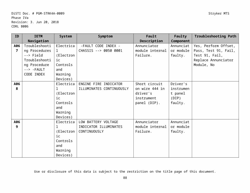
DiSTI Doc. # PGM-STRK4A-0009 Stryker MTS Phase IVaRevision: 3. Jun 20, 2018 CDRL B006
Component ICV ATGM MCV FSV MGS
1W202J-7 J3 N N N N Y
1W202J-7 P1 N N N N Y
1W203-7 P1 N N N N Y
1W203-7 P2 N N N N Y
1W203-7 P3 N N N N Y
1W203-7 P4 N N N N Y
1W206-7 N N N N Y
1W206-7 P1 N N N N Y
1W206-7 P2 N N N N Y
1W206-7 P3 N N N N Y
1W210-7 P1 N N N N Y
1W210-7 P2 N N N N Y
1W215A-7 N N N N Y
1W215A-7 J1 N N N N Y
1W215A-7 P1 N N N N Y
1W215A-7 P2 N N N N Y
1W215A-7 P3 N N N N Y
1W215B-7 N N N N Y
1W215B-7 P1 N N N N Y
1W215B-7 P2 N N N N Y
1W215B-7 P3 N N N N Y
1W215C-7 P1 N N N N Y
Component ICV ATGM MCV FSV MGS
1W216-7 P1 N N N N Y
1W216-7 P2 N N N N Y
1W217-7 N N N N Y
1W217-7 P2 N N N N Y
1W217-7 P3 N N N N Y
1W217-7 P4 N N N N Y
1W217-7 P5 N N N N Y
1W220-7 J2A N N N N Y
1W220-7 J2A Cap N N N N Y
1W221-7 J2B N N N N Y
1W221-7 J2B Cap N N N N Y
1W221-7 P1 N N N N Y
1W2S411-7 P1 N N N N Y
1W301-7 P2 N N N N Y
1W301-7 P3 N N N N Y
1W302-7 P1 N N N N Y
1W302-7 P2 N N N N Y
1W303-7 P2 N N N N Y
1W303-7 P3 N N N N Y
1W304-7 P1 N N N N Y
1W304-7 P2 N N N N Y
1W304-7 P3 N N N N Y
Use or disclosure of this data is subject to the restriction on the title page of this document.
89

DiSTI Doc. # PGM-STRK4A-0009 Stryker MTS Phase IVaRevision: 3. Jun 20, 2018 CDRL B006
Component ICV ATGM MCV FSV MGS
1W305-7 P2 N N N N Y
1W3-7 J1 Cap N N N N Y
1W3-7 P1 N N N N Y
1W400-7 P1 N N N N Y
1W401A-7 N N N N Y
1W401A-7 J1 N N N N Y
1W401A-7 J2 N N N N Y
1W401A-7 J3 N N N N Y
1W401A-7 P1 N N N N Y
1W401A-7 P2 N N N N Y
1W401A-7 P3 N N N N Y
1W401A-7 P4 N N N N Y
1W401A-7 P5 N N N N Y
1W412-7 P1 N N N N Y
1W501-7 P1 N N N N Y
1W501-7 P4 N N N N Y
1W700-7 J1 N N N N Y
1W700-7 J2 N N N N Y
1W700-7 P2 N N N N Y
1W700-7 P3 N N N N Y
24 Inch Wood Block N N N N Y
50 Cal - RWS RS Y N N N N
Component ICV ATGM MCV FSV MGS
A/C Compressor #2 Y Y Y Y Y
A/C Manifold #2 Y Y Y Y Y
A/C Manifold #2 High Pressure Port Cap Y Y Y Y Y
A/C Manifold #2 Low Pressure Port Cap Y Y Y Y Y
A/C Manifold #2 Lower Hose Y Y Y Y Y
A/C Manifold #2 Upper Hose Y Y Y Y Y
Accessory Manifold Pressure Protection Valve Y Y Y Y Y
Accessory Panel Y Y Y Y Y
Accessory Panel Eight-Wheel Drive Select Switch Y Y Y Y Y
Accessory Panel Ramp Switch Y Y Y Y Y
Accessory Panel Transfer Case Speed Switch Y Y Y Y Y
ACP Eight-Wheel Drive LED Y Y Y Y Y
ACP Ramp Open LED Y Y Y Y Y
ACP Transfer Case Low Speed Selected LED Y Y Y Y Y
Actuator Rod - Transmission Parking Brake Y Y Y Y Y
Use or disclosure of this data is subject to the restriction on the title page of this document.
90

DiSTI Doc. # PGM-STRK4A-0009 Stryker MTS Phase IVaRevision: 3. Jun 20, 2018 CDRL B006
Component ICV ATGM MCV FSV MGS
AFES CEP Y Y Y Y Y
AFES CEP Grounding Strap Y Y Y Y Y
AFES CEP Safety Wire on Troop Switch Guard Y Y Y Y Y
AFES CEP Switch Guard for Troop Discharge Switch Y Y Y Y Y
AFES CEP Troop Compartment Manual Discharge Switch Y Y Y Y Y
AFES CEP: CEP LED Y Y Y Y Y
AFES CEP: E1 LED Y Y Y Y Y
AFES CEP: E2 LED Y Y Y Y Y
AFES CEP: E3 LED Y Y Y Y Y
AFES CEP: E7 LED Y Y Y Y Y
AFES CEP: E8 LED Y Y Y Y Y
AFES CEP: Reset Button Y Y Y Y Y
AFES CEP: S1 LED Y Y Y Y Y
AFES CEP: S2 LED Y Y Y Y Y
AFES CEP: S3 LED Y Y Y Y Y
AFES CEP: S4 LED Y Y Y Y Y
AFES CEP: S5 LED Y Y Y Y Y
AFES CEP: S6 LED Y Y Y Y Y
AFES CEP: S7 LED Y Y Y Y Y
Component ICV ATGM MCV FSV MGS
AFES CEP: SYSTEM ON Light Y Y Y Y Y
AFES CEP: Test Button Y Y Y Y Y
Air Compressor Y Y Y Y Y
Air Compressor Coolant Supply Hose Y Y Y Y Y
Air Compressor Governor Female Quick-Disconnect Y Y Y Y Y
Air Compressor Governor Male Quick-Disconnect Y Y Y Y Y
Air Compressor Pneumatic Supply Hose Y Y Y Y Y
Air Compressor Pressure Hose Female Quick-Disc Y Y Y Y Y
Air Conditioner Bellows Y Y Y Y Y
Air Diffuser Y Y Y Y Y
Air Governor Y Y Y Y Y
Air Inlet Diffuser Cover Y Y Y Y Y
Air Inlet Solenoid Text Nav Y Y Y Y Y
Air Outlet Grille Inspection Y Y Y Y Y
Air Pre-Cleaner Y Y Y Y Y
Air Ventilation Switch 1 LED Y Y Y Y Y
Air Ventilation Switch 2 LED Y Y Y Y Y
Alternator Belt Y Y Y Y Y
Use or disclosure of this data is subject to the restriction on the title page of this document.
91

DiSTI Doc. # PGM-STRK4A-0009 Stryker MTS Phase IVaRevision: 3. Jun 20, 2018 CDRL B006
Component ICV ATGM MCV FSV MGS
Alternator Clamp (Inner) Y Y Y Y Y
Alternator Clamp (Outer) Y Y Y Y Y
Alternator Idler Pulley Y Y Y Y Y
Alternator Lifting Sling Y Y Y Y Y
Alternator Lower Bracket Bolt Y Y Y Y Y
Alternator Lower Support Bracket Y Y Y Y Y
Alternator Pulley Nut Y Y Y Y Y
Alternator Upper Bracket Bolt Y Y Y Y Y
Ammo Box Holder Y N N N N
Ammunition Box Y N N N N
Ammunition Box Cover Y N N N N
Ammunition Box Holder Y N N N N
Ammunition Box Holder Installed Y N N N N
Ammunition Box Installed Y N N N N
Annunciator Panel Y Y Y Y Y
Annunciator Panel Acknowledge Button Y Y Y Y Y
Annunciator Panel Grounding Strap Y Y Y Y Y
Component ICV ATGM MCV FSV MGS
Annunciator Panel Mute Button Y Y Y Y Y
Annunciator Panel Test Button Y Y Y Y Y
ANP ABS Fault Indicator Y Y Y Y Y
ANP Acknowledge Push Button Indicator Y Y Y Y Y
ANP Alternator Fault Indicator Y Y Y Y Y
ANP Annunciator Panel Fault Indicator Y Y Y Y Y
ANP Backup Steering Pump Failure Light Y Y Y Y Y
ANP Check Engine Lamp Y Y Y Y Y
ANP Check PPI LED Y Y Y Y Y
ANP Check Transmission on Annunciator Panel Y Y Y Y Y
ANP Chemical Agent Indicator Light Y Y Y Y Y
ANP CTIS Failure Indicator Y Y Y Y Y
ANP Engine Coolant Temperature Indicator Y Y Y Y Y
ANP Engine Fire Light Y Y Y Y Y
ANP Engine Oil Pressure Indicator Y Y Y Y Y
Use or disclosure of this data is subject to the restriction on the title page of this document.
92

DiSTI Doc. # PGM-STRK4A-0009 Stryker MTS Phase IVaRevision: 3. Jun 20, 2018 CDRL B006
Component ICV ATGM MCV FSV MGS
ANP Hydraulic Fluid Level Indicator Y Y Y Y Y
ANP Hydraulic Fluid Temperature Indicator Y Y Y Y Y
ANP Laser Warning Indicator Y Y Y Y Y
ANP Low Air Pressure Indicator Y Y Y Y Y
ANP Low Battery Voltage Indicator Y Y Y Y Y
ANP Low Fuel Indicator Y Y Y Y Y
ANP Mute Push Button Indicator Y Y Y Y Y
ANP Parking Brake ON Indicator Y Y Y Y Y
ANP Radiation Warning Indicator (RADIAC) Y Y Y Y Y
ANP Restricted Air Flow Indicator Y Y Y Y Y
ANP Towed Vehicle Brakes Engaged Indicator Y Y Y Y Y
ANP Transmission Fluid Temperature Indicator Y Y Y Y Y
ANP Voltage Regulator Fault Indicator Y Y Y Y Y
Component ICV ATGM MCV FSV MGS
Antenna Switch N Y N N N
Anti-Recoil Plug on E1 Y Y Y Y Y
Anti-Recoil Plug on E2 Y Y Y Y Y
Anti-Recoil Plug on E3 Y Y Y Y Y
Anti-Recoil Plug on E7 Y Y Y Y Y
Anti-Recoil Plug on E8 Y Y Y Y Y
ARM Switch Guard Y N N N N
Arm Switch on FCU Y N N N N
ATGM GDA FCS Malf N Y N N N
ATGM GDA NVS_Not_Cool Malf N Y N N N
ATGM GDA TAS Malf N Y N N N
Autloader Solenoid Replay Box Circuit Breaker N N N N Y
AUTO 1 Battery Y Y Y Y N
AUTO 2 Battery Y Y Y Y N
AUTO Battery 1 Negative Terminal (Cable Assy 5D) Y Y Y Y N
AUTO Battery 1 Positive Terminal (Cable Assy 68) Y Y Y Y N
AUTO Battery 2 Negative Terminal (Cable Assy 68) Y Y Y Y N
AUTO Battery 2 Positive Terminal (Cable Assy 6A) Y Y Y Y N
Use or disclosure of this data is subject to the restriction on the title page of this document.
93

DiSTI Doc. # PGM-STRK4A-0009 Stryker MTS Phase IVaRevision: 3. Jun 20, 2018 CDRL B006
Component ICV ATGM MCV FSV MGS
Auto Master Switch Y Y N N Y
Autoloader Controller (ALC) N N N N Y
Autoloader Solenoid Relay Box N N N N Y
Aux Master Switch Y Y N N Y
Azimuth Clutch Y N N N N
Azimuth Clutch (Manual Mode Release Lever) Y N N N N
Azimuth Position Assembly (APA) N Y N N N
Azimuth Position Hatch Clear LED on the Loader's P N Y N N N
Azimuth Position Left Ready LED on the Loader's Pa N Y N N N
Azimuth Travel Lock Y N N N N
Background to cover hotspots when PP removed Y Y Y Y Y
Backup Steering Pump Y Y Y Y Y
Backup Steering Pump Return Hose Y Y Y Y Y
Backup Steering Pump Supply Hose Female Quick-Disc Y Y Y Y Y
Barbed Hose Fitting - Tube - Drain Pan N N N N Y
Component ICV ATGM MCV FSV MGS
Base Mount N N Y N N
Battery Box Y Y Y Y N
Battery Box Clamping Frame Y Y Y Y N
Battery Box Clamping Frame Y Y Y Y N
Battery Box Cover Y Y Y Y N
Battery Box Cover Y Y Y Y N
Battery Interconnect Switch Y Y Y Y Y
Battery Isolator ALT Terminal Boot Y Y Y Y N
Battery Isolator Terminal ALT, W4, Cables 2 and 2A Y Y Y Y N
Battery Power Source (BPS) N Y N N N
Battle Hatch LED Y N N N N
Battle Hatch LED - HOT Y N N N N
Battle Override LED Y N N N N
Battle Override LED - HOT Y N N N N
Battle Override Switch Y N N N N
Battle Override Switch Guard Y N N N N
Bay Door Y Y Y Y Y
BCF Thumb Joystick N Y N N N
Use or disclosure of this data is subject to the restriction on the title page of this document.
94

DiSTI Doc. # PGM-STRK4A-0009 Stryker MTS Phase IVaRevision: 3. Jun 20, 2018 CDRL B006
Component ICV ATGM MCV FSV MGS
Beam Sling N N N N Y
Beam Sling (Forward Left Leg) N N N N Y
Beam Sling (Forward Right Leg) N N N N Y
Beam Sling (Rear Left Leg) N N N N Y
Beam Sling (Rear Right Leg) N N N N Y
Blackout Video Button on VDT Y Y Y Y Y
Blank display Y Y Y Y Y
Blower Motor #1 Y N N N N
Blower Motor #1 Scroll Housing Y N N N N
Blower Motor #2 Y N N N N
Blower Motor #2 Scroll Housing Y N N N N
Blower Panel Y N N N N
Bottom Left M6 Grenade Launcher Y N N N N
Bottom Right M6 Grenade Launcher Y N N N N
Brake Pedal Y Y Y Y Y
Brake Pedal Image Y Y Y Y Y
Breech Adapter Lock N N N N Y
Component ICV ATGM MCV FSV MGS
Breech Cam N N N N Y
Breech Collar N N N N Y
Breech Cylinder N N N N Y
Breech Cylinder Lower Hydraulic Hose N N N N Y
Breech Cylinder Lwr Hydraulic Hose Cylinder Connec N N N N Y
Breech Cylinder Lwr Hydraulic Hose Manifold Connec N N N N Y
Breech Cylinder Relief Valve N N N N Y
Breech Cylinder Screws N N N N Y
Breech Cylinder Upper Hydraulic Hose N N N N Y
Breech Cylinder Upr Hydraulic Hose Cylinder Connec N N N N Y
Breech Cylinder Upr Hydraulic Hose Manifold Connec N N N N Y
Breech Ejection Cam N N N N Y
Breech Manual Operating Handle N N N N Y
Breech Mechanism N N N N Y
Use or disclosure of this data is subject to the restriction on the title page of this document.
95

DiSTI Doc. # PGM-STRK4A-0009 Stryker MTS Phase IVaRevision: 3. Jun 20, 2018 CDRL B006
Component ICV ATGM MCV FSV MGS
Breech Open Sensor N N N N Y
Breech Retaining Bolt N N N N Y
Breech Ring N N N N Y
Breech Rope - Lanyard N N N N Y
Breech Sensor Bracket N N N N Y
Breech Support Tool N N N N Y
Breechblock N N N N Y
BRIGHTNESS- Button on FCU Y N N N N
BRIGHTNESS+ Button on FCU Y N N N N
Bulkhead Frame Around Panel 1 Y Y Y Y Y
Bulkhead Frame Around Panel 2 Y Y Y Y Y
CA 5D at Auto 1 Neg Connected Y Y Y Y N
CA 5D at Auto 1 Neg Disconnected Y Y Y Y N
CA 68 at Auto 1 Pos Connected Y Y Y Y N
CA 68 at Auto 1 Pos Disconnected Y Y Y Y N
CA 68 at Auto 2 Neg Disconnected Y Y Y Y N
Component ICV ATGM MCV FSV MGS
CA 6A at Auto 2 Pos Connected Y Y Y Y N
CA 6A at Auto 2 Pos Disconnected Y Y Y Y N
Cable 4BA at PDP 2 Y Y Y Y Y
Cable 4BA Insulator Cap Y Y Y Y Y
Cable 5A at Battery box left side cable boot Y Y Y Y N
Cable 5A Battery Box Insulator Cap Y Y Y Y N
Cable 5A2 at PDP 2 Y Y Y Y Y
Cable 5A2 Insulator Cap Y Y Y Y Y
Cable 5C Battery Box Insulator Cap Y Y Y Y N
Cable 5C Battery Box Left Side Y Y Y Y N
Cable 6B 6E Battery Box Boot Y Y Y Y N
Cable 81/82 Boot at TB1 Y Y Y Y Y
Cable Assemblies 4B and 4BA at FT1A Terminal Y Y Y Y N
Cable Assemblies 4F and 4FA at FT1 Terminal Y Y Y Y N
Cable Assemblies 6B and 6E at FT3 Terminal Y Y Y Y N
Use or disclosure of this data is subject to the restriction on the title page of this document.
96

DiSTI Doc. # PGM-STRK4A-0009 Stryker MTS Phase IVaRevision: 3. Jun 20, 2018 CDRL B006
Component ICV ATGM MCV FSV MGS
Cable Assembly 3A1 on Alternator Y Y Y Y Y
Cable Assembly 3A2 on Alternator Y Y Y Y Y
Cable Assembly 3B Y Y Y Y Y
Cable Assembly 5A at Outer Battery Box Y Y Y Y N
Cable Assembly 5C at Outer Battery Box Y Y Y Y N
Cable Assembly Cover on Cables 4B, 4BA, 4F, 4FA Y Y Y Y N
Cable Boot on Alternator Installed Image Y Y Y Y Y
Cable Boot on Alternator Pulled Back Image Y Y Y Y Y
Cable Boot on Engine Alternator Cable 2 Y Y Y Y Y
Cable Boot on Engine Alternator Cable 2A Y Y Y Y Y
Cable Boot on Engine Alternator Cable 3A1 Y Y Y Y Y
Cable Boot on Engine Alternator Cable 3A2 Y Y Y Y Y
Cable Boot on ISO ALT CA 2 P2 Y Y Y Y N
Component ICV ATGM MCV FSV MGS
Cable Boot Removed on ISO ALT CA2 P2 Y Y Y Y N
Cable No. 1 P2 at CPVEU TJ1 N N N N Y
Cable No. 1 P2 at DCA Test Adapter and DCA J4 N N N N Y
Cable No. 1 P2 at DCA Test Adapter and J1 of 1W3-7 N N N N Y
Canister Latch Solenoid Relay Box Circuit Breaker N N N N Y
Cap on Cable 81/82 Boot at TB1 Y Y Y Y Y
Card Rack Assembly (CRA) N Y N N N
Carousel Ball Valve Handle N N N N Y
Carousel Canister Tube 1 N N N N Y
Carousel Canister Tube 2 N N N N Y
Carousel Canister Tube 3 N N N N Y
Carousel Canister Tube 4 N N N N Y
Carousel Canister Tube 5 N N N N Y
Carousel Canister Tube 6 N N N N Y
Carousel Canister Tube 7 N N N N Y
Carousel Canister Tube 8 N N N N Y
Carousel Enclsre Left Front Panel N N N N Y
Use or disclosure of this data is subject to the restriction on the title page of this document.
97

DiSTI Doc. # PGM-STRK4A-0009 Stryker MTS Phase IVaRevision: 3. Jun 20, 2018 CDRL B006
Component ICV ATGM MCV FSV MGS
Carousel Enclsre Left Rear Panel N N N N Y
Carousel Enclsre Right Front Panel N N N N Y
Use or disclosure of this data is subject to the restriction on the title page of this document.
98

DiSTI Doc. # PGM-STRK4A-0009 Stryker MTS Phase IVaRevision: 3. Jun 20, 2018 CDRL B006
Carousel Enclsre Right Rear Panel N N N N Y
Carousel Enclsre Top Panel N N N N Y
Use or disclosure of this data is subject to the restriction on the title page of this document.
99

DiSTI Doc. # PGM-STRK4A-0009 Stryker MTS Phase IVaRevision: 3. Jun 20, 2018 CDRL B006
Carousel Gauge Tool N N N N Y
Carousel Left Canister Empty Switch N N N N Y
Carousel Left Canister Empty Switch Bracket N N N N Y
Carousel Lower Ammunition Retainer Plunger N N N N Y
Carousel Manual Operating Handle N N N N Y
Carousel Manual Operating Lever N N N N Y
Cat A Button Y Y Y Y Y
Cat A Button - HOT Y Y Y Y Y
Caution/Warning Y Y Y Y Y
Caution/Warning - HOT Y Y Y Y Y
CB13 on PDP Y Y Y Y Y
CB14 on PDP Y Y Y Y Y
CB17 on PDP Y Y Y Y Y
CB18 on PDP Y Y Y Y Y
CB19 on PDP Y Y Y Y Y
CB20 on PDP Y Y Y Y Y
CB21 on Accessory Panel Y Y Y Y Y
CB22 on Accessory Panel Y Y Y Y Y
CB22 on PDP Y Y Y Y Y
CB26 on PDP Y Y Y Y Y
CB30 on PDP Y Y Y Y Y
CB5 on the PDP Y Y Y Y Y
CCH Designate Button N N N N Y
CCH Designate Button Guard N N N N Y
CCH Load Button N N N N Y
CCH Palm Switch N N N N Y
CCH Trigger Switch N N N N Y
CCP 0 Button N N N N Y
CCP 1 Button N N N N Y
CCP 2 Button N N N N Y
CCP 3 Button N N N N Y
CCP 4 Button N N N N Y
CCP 5 Button N N N N Y
CCP 6 Button N N N N Y
CCP 7 Button N N N N Y
CCP 8 Button N N N N Y
CCP 9 Button N N N N Y
CCP A/N Button N N N N Y
CCP APDS Button N N N N Y
CCP APERS Button N N N N Y
CCP Armed/Safe Switch N N N N Y
Use or disclosure of this data is subject to the restriction on the title page of this document.
100

DiSTI Doc. # PGM-STRK4A-0009 Stryker MTS Phase IVaRevision: 3. Jun 20, 2018 CDRL B006
CCP AUTO/MAN Button N N N N Y
CCP Autoloader On/Off Switch N N N N Y
CCP Autoloader Select Knob N N N N Y
CCP Battle Switch N N N N Y
CCP BHOT/WHOT Button N N N N Y
CCP BRT/Contrast Down Button N N N N Y
CCP BRT/Contrast Up Button N N N N Y
CCP Clockwise Button N N N N Y
CCP Combat Override/Normal Switch N N N N Y
CCP Combat Override/Normal Switch Guard N N N N Y
CCP Commander's Display/Mode Knob N N N N Y
CCP CONTR Button N N N N Y
CCP Counter Clockwise Button N N N N Y
CCP Decimal Button N N N N Y
CCP Display Power On/Off Button N N N N Y
CCP Drift/Focus Button N N N N Y
CCP ENT Button N N N N Y
Use or disclosure of this data is subject to the restriction on the title page of this document.
101

DiSTI Doc. # PGM-STRK4A-0009 Stryker MTS Phase IVaRevision: 3. Jun 20, 2018 CDRL B006
CCP F1 Button N N N N Y
CCP F2 Button N N N N Y
CCP F3 Button N N N N Y
CCP F4 Button N N N N Y
CCP F5 Button N N N N Y
CCP F6 Button N N N N Y
CCP FCS On/Off Switch N N N N Y
CCP Fire Control 4-Way Switch N N N N Y
CCP FOV Button N N N N Y
CCP Ground Strap N N N N Y
CCP GTD On/Off Switch N N N N Y
CCP HEAT Button N N N N Y
CCP HEP Button N N N N Y
CCP INS OVR Button N N N N Y
CCP L1 Menu Option Button N N N N Y
CCP L2 Menu Option Button N N N N Y
CCP L3 Menu Option Button N N N N Y
CCP L4 Menu Option Button N N N N Y
CCP L5 Menu Option Button N N N N Y
CCP L6 Menu Option Button N N N N Y
CCP Load Button N N N N Y
CCP MAIN/COAX Switch N N N N Y
CCP MAST Button N N N N Y
CCP Minus Button N N N N Y
CCP Pan Viewer 4-Way Switch N N N N Y
CCP Panel Test Button N N N N Y
CCP R1 Menu Option Button N N N N Y
CCP R2 Menu Option Button N N N N Y
CCP R3 Menu Option Button N N N N Y
CCP R4 Menu Option Button N N N N Y
CCP R5 Menu Option Button N N N N Y
CCP R6 Menu Option Button N N N N Y
CCP RET/SYMB Button N N N N Y
CCP Salvo 1 Fire/Off Switch N N N N Y
CCP Salvo 1 Fire/Off Switch Guard N N N N Y
CCP Salvo 2 Fire/Off Switch N N N N Y
CCP Salvo 2 Fire/Off Switch Guard N N N N Y
CCP SENS/CTRS Button N N N N Y
CCP Shock Mounts N N N N Y
Use or disclosure of this data is subject to the restriction on the title page of this document.
102

DiSTI Doc. # PGM-STRK4A-0009 Stryker MTS Phase IVaRevision: 3. Jun 20, 2018 CDRL B006
CCP Spare1 Button N N N N Y
CCP Spare2 Button N N N N Y
CCP Spare3 Button N N N N Y
CCP SPC Button N N N N Y
CCP SRCH/MGR Button N N N N Y
CCP STAB On/Off Switch N N N N Y
CCP Training Mode Switch N N N N Y
CCP Training Mode Switch Guard N N N N Y
CCP Turret On/Off Switch N N N N Y
CDU CONTR Button N N N N Y
CDU Down Button N N N N Y
CDU Shock Mounts N N N N Y
CDU Test Button N N N N Y
CDU Up Button N N N N Y
Center Mast Protection Cover N Y N N N
Central Control Panel (CCP) N N N N Y
CH FCH Charge Fitting Flared Cap Y Y Y Y Y
CH FCH Charge Fitting Setscrew Y Y Y Y Y
CH/FCH Charge Fitting Set Screw Y Y Y Y Y
Charge Air Cooler Outlet Tube Y Y Y Y Y
Charging Station High Pressure Hose Y Y Y Y Y
Charging Station High Pressure Hose Valve Y Y Y Y Y
Charging Station Low Pressure Hose Y Y Y Y Y
Charging Station Low Pressure Hose Valve Y Y Y Y Y
Climate Control Module Heater Control Switch Y Y Y Y Y
Climate Control Module Left Air Ventilation Switch Y Y Y Y Y
Climate Control Module Right Ventilation Switch Y Y Y Y Y
Climate Control Module Vent Fan Switch Y Y Y Y Y
Climate Control Unit (CCU) Y Y Y Y Y
Climate Control Unit Grounding Strap Y Y Y Y Y
Climate Ctrl Module Heater Blower Sw - Left Troop Y Y Y Y Y
Climate Ctrl Module Heater Blower Sw - Rt Troop Y Y Y Y Y
Climate Ctrl Module Heater Blower Switch - Driver Y Y Y Y Y
Use or disclosure of this data is subject to the restriction on the title page of this document.
103

DiSTI Doc. # PGM-STRK4A-0009 Stryker MTS Phase IVaRevision: 3. Jun 20, 2018 CDRL B006
CMS Armor Panel 17 N N N N Y CMS Armor Panel 18 N N N N Y
Use or disclosure of this data is subject to the restriction on the title page of this document.
104

DiSTI Doc. # PGM-STRK4A-0009 Stryker MTS Phase IVaRevision: 3. Jun 20, 2018 CDRL B006
CMS Armor Panel 19 N N N N Y
CMS Armor Panel 20 N N N N Y
CMS Armor Panel 21 N N N N Y
CMS Ballistic Cover Assembly N N N N Y
CMS Ballistic Door N N N N Y
CMS Browpad N N N N Y
CMS Day Sight Eyepiece N N N N Y
CMS Day Window N N N N Y
CMS Drift Control Assembly N N N N Y
CMS Lifting Kit N N N N Y
CMS Sight Body N N N N Y
CMS Sight Body Screws N N N N Y
CMS Thermal Sight Eyepiece N N N N Y
Cocking Actuator Y N N N N
Cocking Bracket Y N N N N
Collector Sleeve Y N N N N
Collimator MRS Cell N N N N Y
Collimator MRS Lens N N N N Y
Collimator MRS Locking Ring N N N N Y
Collimator MRS Window N N N N Y
Collimator Muzzle Reference Sensor (MRS) N N N N Y
Commander’s Wire Cutter N N N Y N
Commander's Control Panel N Y N N N
Commander's Display Unit (CDU) N N N N Y
Commander's Display Unit (CDU) N N N N Y
Commander's Foot Rest Y N N N N
Commander's Hand Station N N N N Y
Commander's Hand Station N N N N Y
Commander's Hatch Y Y Y Y N
Commander's Hatch N N N N Y
Commander's Hatch Combat Lock N N N N Y
Commander's Lower Turret Basket Screen N N N N Y
Commander's Map Light Y N N N N
Commander's Panel Assembly Y N N N N
Commander's Periscope 1 N N N N Y
Commander's Periscope 2 N N N N Y
Commander's Periscope 3 N N N N Y
Commander's Periscope 4 N N N N Y
Commander's Periscope 5 N N N N Y
Use or disclosure of this data is subject to the restriction on the title page of this document.
105

DiSTI Doc. # PGM-STRK4A-0009 Stryker MTS Phase IVaRevision: 3. Jun 20, 2018 CDRL B006
Commander's Periscope 6 N N N N Y
Commander's Periscope 7 N N N N Y
Commander's Seat N N N N Y
Commander's Seat Guard Lower Brackets Y Y Y Y Y
Commander's Turret Azimuth Lock N N N N Y
Commander's Turret Azimuth Lock Sensor N N N N Y
Commander's Turret Foot Guard N N N N Y
Commander's Upper Turret Basket Door N N N N Y
Commander's Upper Turret Basket Screen N N N N Y
Commander's VFM Hose Y N N N N
Commander's VFM Tube N N N N Y
Compass Display Y N N N N
Compass Display - HOT Y N N N N
Compass Needle Y N N N N
Compass Needle - HOT Y N N N N
Compressed air adapter to prk brk actuator hose Y Y Y Y Y
Compressed Air Source Adapter Valve Y Y Y Y Y
Use or disclosure of this data is subject to the restriction on the title page of this document.
106

DiSTI Doc. # PGM-STRK4A-0009 Stryker MTS Phase IVaRevision: 3. Jun 20, 2018 CDRL B006
Connector J16 of the ECM Y Y Y Y Y
Connector P36 at IAP Control Solenoid J36 Y Y Y Y Y
Connector P36 at IAP Control Solenoid J36 Y Y Y Y Y
Control Arm (straight and tilted) Y Y Y Y Y
Control Grip Y N N N N
Control Grip Charge Button Y N N N N
Control Grip Day/Night button Y N N N N
Control Grip Enable Switch Y N N N N
Control Grip IR Button Y N N N N
Control Grip LRF Button Y N N N N
Control Grip MAG Switch Y N N N N
Control Grip NULL Button Y N N N N
Control Grip STAB Button Y N N N N
Control Grip Trigger Switch Y N N N N
Control Grip Trigger Switch Guard Y N N N N
Control Grip VIS AIM button Y N N N N
Coolant Overflow Reservoir Y Y Y Y Y
Coolant Pump Y Y Y Y N
Coolant Pump Inlet Hose Y Y Y Y N
Coolant Pump Outlet Hose Y Y Y Y N
Cooling Fan Assembly Y Y Y Y Y
Cooling Fan Bellows Y Y Y Y Y
Cooling Fan Bellows Y Y Y Y Y
Cooling Fan Impeller Y Y Y Y Y
Cooling Grille Assembly Y Y Y Y Y
Cooling Grille Assembly Bolts Y Y Y Y Y
CPDU CB5 Y Y Y Y Y
CPV N N N N Y
CPV Access Door N N N N Y
CPV Access Door N N N N Y
CPV Bottom Five Screws N N N N Y
CPV Mounting Shims N N N N Y
CPV Top Two Screws N N N N Y
CPVEU N N N N Y
CPVEU Cover N N N N Y
CPVEU TJ1 Cap N N N N Y
Crankshaft Y Y Y Y Y
Crew/Driver Coolant Hose Y Y Y Y N
Crew/Driver Diverter Valve Y Y Y Y N
Crew/Driver Diverter Valve Y Y Y Y N
Crosswind Sensor N N N N Y
Use or disclosure of this data is subject to the restriction on the title page of this document.
107

DiSTI Doc. # PGM-STRK4A-0009 Stryker MTS Phase IVaRevision: 3. Jun 20, 2018 CDRL B006
Crosswind Sensor Support N N N N Y
CTIS (Central Tire Inflation System) Manifold Y Y Y Y Y
CTIS Controller Assembly Y Y Y Y Y
CTIS Cross Country LED Y Y Y Y Y
CTIS Emergency LED Y Y Y Y Y
CTIS Highway LED Y Y Y Y Y
CTIS Low Pressure LED Y Y Y Y Y
CTIS Manifold C1 Y Y Y Y Y
CTIS Manifold C10 Y Y Y Y Y
CTIS Manifold C11 Y Y Y Y Y
CTIS Manifold C2 Y Y Y Y Y
CTIS Manifold C5 Y Y Y Y Y
CTIS Manifold C9 Y Y Y Y Y
CTIS Manifold Exhaust Hose Y Y Y Y Y
CTIS Manifold Ground Strap Y Y Y Y Y
CTIS Manifold W468 Y Y Y Y Y
CTIS Mud Sand Snow LED Y Y Y Y Y
CTIS On/Off Toggle Switch Y Y Y Y Y
CTIS Shutoff Valve at Power Entry Panel Y Y Y Y Y
CTIS Start Button Y Y Y Y Y
CTIS Terrain Setting Switch Y Y Y Y Y
Current Elevation Y N N N N
Current Elevation - HOT Y N N N N
DAGR Mounting Adapter Y N N N N
DAGR Mounting Bracket Y N N N N
Day.Night Vision Video Button on VDT Y Y Y Y Y
DCA Test Adapter N N N N Y
DCA Test Adapter N N N N Y
DCH Charge Fitting Flared Cap Y Y Y Y Y
DCH Charge Fitting Set Screw Y Y Y Y Y
DCH Charge Fitting Setscrew Y Y Y Y Y
Delete Y Y Y Y Y
Delete Y Y Y Y Y
DELETE Replace Mask for PDP Y Y Y Y Y
Diagnostic Control Unit (DCU) Y Y Y Y Y
Diagnostic Control Unit (DCU) Y Y Y Y Y
Digital Control Assembly N N N N Y
Dimmer Knob N N N N Y
Use or disclosure of this data is subject to the restriction on the title page of this document.
108

DiSTI Doc. # PGM-STRK4A-0009 Stryker MTS Phase IVaRevision: 3. Jun 20, 2018 CDRL B006
DIP Light Image to hide panels Y Y Y Y Y
Dispersement Nozzle on E2 Y Y Y Y Y
Use or disclosure of this data is subject to the restriction on the title page of this document.
109

DiSTI Doc. # PGM-STRK4A-0009 Stryker MTS Phase IVaRevision: 3. Jun 20, 2018 CDRL B006
Display Window on Battery Power Source (BPS) N Y N N N
Diverter Valve Assembly Y Y Y Y N
Dome Light Override Switch Y Y Y Y Y
Down/Right Button on VDT Y Y Y Y Y
Drain Hose Y Y Y Y Y
Drive Shaft (Transfer Case) U Joint Y Y Y Y Y
Driver's Bulkhead Fitting Protective Plate Y Y Y Y Y
Driver's Foot Pedal Actuator (brake) - BPAA Y Y Y Y Y
Driver's Hatch Y Y Y Y Y
Driver's Hatch Combat Lock Y Y Y Y Y
Driver's Hatch Cover Y Y Y Y Y
Driver's Hatch Limit Switch N N N N Y
Driver's Hatch Stop Y Y Y Y Y
Driver's Instrument Panel (DIP) Y Y Y Y Y
Driver's Seat Y Y Y Y Y
Driver's Seat Assembly Platform Y Y Y Y Y
Driver's Seat Belt Brackets Y Y Y Y Y
Driver's Seat Front Composite Floor Plate Y Y Y Y Y
Driver's Seat Front Quick Release Pins Y Y Y Y Y
Driver's Seat Height-Adjustment Switch Y Y Y Y Y
Driver's Seat Hoisting Straps Y Y Y Y Y
Driver's Seat Pedal-Adjustment Switch Y Y Y Y Y
Driver's Seat Plate Y Y Y Y Y
Driver’s Seat Rear Composite Plate Y Y Y Y Y
Driver's Seat Rear Quick Release Pins Y Y Y Y Y
Driver's Vision Enhancer Display Module (DVE) Y Y Y Y Y
Driver's Wire Cutter Y Y Y Y Y
Drum - Transmission Parking Brake Y Y Y Y Y
DVE Power Switch Y Y Y Y Y
DVE Sensor Module Y Y Y Y Y
DVE Sensor Module Bracket Y Y Y Y Y
DVE Video Button on VDT Y Y Y Y Y
DVE Video Switch Y Y Y Y Y
E8 on W436 Y Y Y Y Y
Eagle Screen Y Y N N Y
Use or disclosure of this data is subject to the restriction on the title page of this document.
110

DiSTI Doc. # PGM-STRK4A-0009 Stryker MTS Phase IVaRevision: 3. Jun 20, 2018 CDRL B006
Eagle Screen - HOT Y Y N N Y
ECIRTS connected to Missile Launcher N Y N N N
ECM Engine Preheat LED Y Y Y Y Y
Elev Display Y N N N N
Elev Display - HOT Y N N N N
Elevating Gear Bracket N N Y N N
Elevating Handwheel N N Y N N
Elevating Upper Angle Drive Unit N N Y N N
Elevation Drive Brake Clutch N N N N Y
Elevation Drive Brake Clutch Ground Strap N N N N Y
Elevation Drive Clutch Y N N N N
Elevation Drive Clutch (Manual Mode Release Lever) Y N N N N
Elevation Drive Clutch Connector N N N N Y
Elevation Drive Handstation Connector N N N N Y
Elevation Drive Manual Handle N N N N Y
Elevation Drive Manual Handle Down Button N N N N Y
Use or disclosure of this data is subject to the restriction on the title page of this document.
111

DiSTI Doc. # PGM-STRK4A-0009 Stryker MTS Phase IVaRevision: 3. Jun 20, 2018 CDRL B006
Elevation Drive Manual Handle Up Button N N N N Y
Elevation Drive Motor N N N N Y
Elevation Drive Motor Potentiometer N N N N Y
Elevation Flex Drive Shaft N N N N Y
Elevation Transport Lock Y N N N N
Elevation Transport Lock Y N N N N
ELRF BIT Button N N N N Y
ELRF Display Knob N N N N Y
ELRF First/Last Knob N N N N Y
ELRF Reticle Knob N N N N Y
Emergency Ramp Control Knob Y Y Y Y Y
Emergency Ramp Control Knob Cover Y Y Y Y Y
Endless Nylon Web Sling N N N N Y
Engine Y Y Y Y Y
Engine Access Cavity Y Y Y Y Y
Engine Access Panel 1 Y Y Y Y Y
Engine Access Panel 1 Cavity Y Y Y Y Y
Engine Access Panel 2 Y Y Y Y Y
Engine Access Panel 2 Y Y Y Y Y
Engine Access Panel 3 Y Y Y Y Y
Engine Access Panel 3 Y Y Y Y Y
Engine Access Panel 3 Cavity Y Y Y Y Y
Engine Access Panel 4 Y Y Y Y Y
Engine Access Panel 4 Cavity Y Y Y Y Y
Engine Alternator Y Y Y Y Y
Engine Alternator Cable 2 to Positive Y Y Y Y Y
Engine Alternator Cable 2A to Positive Y Y Y Y Y
Engine Alternator W459-P1 Y Y Y Y Y
Engine Alternator W459-P2 Y Y Y Y Y
Engine Brake Switch Y Y Y Y Y
Engine Control Module (ECM) Y Y Y Y Y
Engine Coolant Heater Return Hose Quick-Disconnect Y Y Y Y Y
Engine Coolant Heater Supply Hose Quick-Disconnect Y Y Y Y Y
Engine Cooling Fan Hub Plate Y Y Y Y Y
Engine Hatch Y Y Y Y Y
Use or disclosure of this data is subject to the restriction on the title page of this document.
112

DiSTI Doc. # PGM-STRK4A-0009 Stryker MTS Phase IVaRevision: 3. Jun 20, 2018 CDRL B006
Engine High Idle Switch Y Y Y Y Y
Engine Oil Gallery Y Y Y Y Y
Engine Oil Outlet Tube at HEUI Oil Pump Y Y Y Y Y
Engine Oil Outlet Tube at HEUI Oil Pump Y Y Y Y Y
Engine Oil Outlet Tube Disc at HEUI Oil Pump Y Y Y Y Y
Engine Oil Pressure Switch W441-P9 Y Y Y Y Y
Engine Oil Temperature Sensor (HEUI Scene) Y Y Y Y Y
Engine Oil Temperature Sensor P105 Connector Y Y Y Y Y
Engine Pre-Heater Diverter Valve Y Y Y Y N
Engine Pre-Heater Diverter Valve Y Y Y Y N
Engine Start Switch Y Y Y Y Y
Engine Thermostat Vent Hose Inspection Y Y Y Y Y
Engine Wiring Harness at Temp Sensor J105 Y Y Y Y Y
Equilibrator Accumulator Cap N N N N Y
Equilibrator Accumulator Upper Nut N N N N Y
Equilibrator Cylinder N N N N Y
Equilibrator Cylinder Elbow N N N N Y
Equilibrator Manifold N N N N Y
Equilibrator Manifold Bracket N N N N Y
Equilibrator Manifold Hose N N N N Y
Equilibrator Manifold Plug N N N N Y
Equilibrator Manifold Pressure Gauge N N N N Y
Equilibrator Manifold Valve Knob N N N N Y
Equilibrator Manifold Valve Lock Ring N N N N Y
Escape/F1 Button on VDT Y Y Y Y Y
Evacuator N N N N Y
Exhaust Brake Valve Y Y Y Y Y
Exhaust Brake Valve at CGA Y Y Y Y Y
Exhaust Brake Valve Elbow Clamp Y N N N N
Exhaust Brake Valve Tube Clamp Y N N N N
Exhaust Elbow Y Y Y Y Y
Use or disclosure of this data is subject to the restriction on the title page of this document.
113

DiSTI Doc. # PGM-STRK4A-0009 Stryker MTS Phase IVaRevision: 3. Jun 20, 2018 CDRL B006
Exhaust Elbow Turbocharger Clamp Y Y Y Y Y
Exhaust Inlet Tube Blanket Y Y Y Y Y
Use or disclosure of this data is subject to the restriction on the title page of this document.
114

DiSTI Doc. # PGM-STRK4A-0009 Stryker MTS Phase IVaRevision: 3. Jun 20, 2018 CDRL B006
Exhaust Outlet Pipe Y Y Y Y Y
Exhaust Outlet Pipe Blanket Y Y Y Y Y
Extension for W475-P1 while connected Y Y Y Y Y
External Air Source PSI Gage Y Y Y Y Y
External Tire Inflation Hose Fitting Y Y Y Y Y
F1 Button on VDT Y Y Y Y Y
F2 Button on VDT Y Y Y Y Y
F3 Button on VDT Y Y Y Y Y
F4 Y Y Y Y Y
F4 Button on VDT Y Y Y Y Y
F5 Button on VDT Y Y Y Y Y
F6 Y Y Y Y Y
F6 Button on VDT Y Y Y Y Y
F7 Button on VDT Y Y Y Y Y
F8 Y Y Y Y Y
F8 Button on VDT Y Y Y Y Y
Fan Assembly Y Y Y Y Y
Fan Motor Y Y Y Y Y
Fault Popup Text for VDT Y Y Y Y Y
Fault Popup Text for VDT - HOT Y Y Y Y Y
FBCB2 Display Isolation Mount N N N N Y
FBCB2 Display Shock Mounts N N N N Y
FCN Button on VDT Y Y Y Y Y
FCS Power On Lamp N Y N N N
FCS Power On Lamp Cover N Y N N N
FCU Ballistic Label Y N N N N
FCU Ballistic Label - HOT Y N N N N
FCU Grounding Strap Y N N N N
Field Of View (FOV) Button on Left Gunner's Handle N Y N N N
Filter Button on Left Gunner's Handle N Y N N N
Fire Control System (FCS) N Y N N N
Fire Control Unit (FCU) Y N N N N
Fire Extinguisher 1 connector on W436 Y Y Y Y Y
Fire Extinguisher 2 connector on W436 Y Y Y Y Y
Fire Extinguisher 3 Connection to W436 Y Y Y Y Y
Fire Extinguisher E1 Hose Assembly Y Y Y Y Y
Fire Extinguisher E3 Hose Assembly Y Y Y Y Y
Use or disclosure of this data is subject to the restriction on the title page of this document.
115

DiSTI Doc. # PGM-STRK4A-0009 Stryker MTS Phase IVaRevision: 3. Jun 20, 2018 CDRL B006
Fire Extinguisher E7 Hose Assembly Y Y Y Y Y
Fire Extinguisher E8 Y Y Y Y Y
Fire Extinguisher E8 Hose Assembly Y Y Y Y Y
Fire Support Panel Assembly (FSPA) N N N Y N
Fire Trigger on Right Gunner's Handle N Y N N N
Firing Circuit Tester N N N N Y
Firing Solenoid Y N N N N
Firing Solenoid P1 Y N N N N
First Axle Left Axle Shaft Y Y Y Y Y
First Axle Left Control Arm Y Y Y Y Y
First Axle Left Control Arm Ball Joint Bolts Y Y Y Y Y
First Axle Left Control Arm Bolts Y Y Y Y Y
First Axle Right Axle Shaft Y Y Y Y Y
First Axle Right Control Arm Y Y Y Y Y
First Axle Right Control Arm Ball Joint Bolts Y Y Y Y Y
First Axle Right Control Arm Bolts Y Y Y Y Y
First Diff Lower Supply Hose (Shift Cylinder) P9 Y Y Y Y Y
Use or disclosure of this data is subject to the restriction on the title page of this document.
116

DiSTI Doc. # PGM-STRK4A-0009 Stryker MTS Phase IVaRevision: 3. Jun 20, 2018 CDRL B006
First Diff Lower Supply Hose (Tee Fitting) P9 Rear Y Y Y Y Y
First Diff Upper Supply Hose (Tee Fitting) P10 Rear Y Y Y Y Y
First Diff Upper Supply Hose (Shift Cylinder) P10 Y Y Y Y Y
First Differential - Workbench Y Y Y Y Y
First Differential Bolts Y Y Y Y Y
First Differential Guard Y Y Y Y Y
First Differential Shift Cylinder Y Y Y Y Y
First Differential Vent Hose Y Y Y Y Y
First Drive Shaft (First Differential) Y Y Y Y Y
First Drive Shaft (Second Differential) Y Y Y Y Y
First/Last Button on Right Gunner's Handle N Y N N N
FOCUS Switch Y N N N N
Forward Armor Door N N N N Y
Forward Armor Door N N N N Y
Forward Armor Door Captive Screws N N N N Y
Forward Left M6 Grenade Launcher Y N N N N
Forward Right M6 Grenade Launcher Y N N N N
Four Breech/Rear Cover Screws N N N N Y
FOV Label Y N N N N
FOV Label - HOT Y N N N N
FRH Filling Port N N Y N N
Front Battery FT1 Protective Boot N N N N Y
Front Battery FT1 Screw N N N N Y
Front Battery FT4 Protective Boot N N N N Y
Front Battery FT4 Screw N N N N Y
Front Casing Collector Brackets Y N N N N
Front Casing Collector Lock Spring Y N N N N
Front Duct Y N N N N
Front Hatch Y Y Y Y Y
Front Seal Retainer Y Y Y Y Y
Front Service Hatch Y Y Y Y Y
Front Vent Fan Cover Y Y Y Y Y
FSS Test Set: Functional Test Switch Y Y Y Y Y
Use or disclosure of this data is subject to the restriction on the title page of this document.
117

DiSTI Doc. # PGM-STRK4A-0009 Stryker MTS Phase IVaRevision: 3. Jun 20, 2018 CDRL B006
FSS Test Set: IN PROGRESS LED Y Y Y Y Y
FSS Test Set: Power Switch Y Y Y Y Y
FSS Test Set: Power Test Button Y Y Y Y Y
FSS Test Set: SENSOR OK LED Y Y Y Y Y
FSS Test Set: Sensor Test Button Y Y Y Y Y
Fuel Gage Not Used Y Y Y Y Y
Fuel Hose at Fuel Transfer Pump Y Y Y Y Y
Fuel Hose at Fuel Transfer Pump Y Y Y Y Y
Fuel Return Hose Female Quick-Disconnect Y Y Y Y Y
Fuel Return Hose Male Quick-Disconnect Y Y Y Y Y
Fuel Supply Hose Bulkhead Connector Y Y Y Y Y
Fuel Supply Hose Female Quick-Disconnect Y Y Y Y Y
Fuel Supply Hose Fuel Filter/Water Separator Quick Y Y Y Y Y
Fuel Supply Hose Male Quick-Disconnect Y Y Y Y Y
Fuel Transfer Pump Y Y Y Y Y
Fuel/Water Separator Plug Y Y Y Y Y
Function Switch on Battery Power Source (BPS) N Y N N N
Fuse on Battery Power Source (BPS) N Y N N N
Gage #1-Oil Pressure Y Y Y Y Y
Gage #2-Fuel Pressure Y Y Y Y Y
Gauge Cluster Unit (GCU) Y Y Y Y Y
GCH Adjustable Assembly N N N N Y
GCH Left Laser Range Finder Button N N N N Y
GCH Left Load Button N N N N Y
GCH Left Palm Switch N N N N Y
GCH Left Trigger Switch N N N N Y
GCH Right Laser Range Finder Button N N N N Y
GCH Right Load Button N N N N Y
GCH Right Palm Switch N N N N Y
GCH Right Trigger Switch N N N N Y
GCP BLK HOT/WHT HOT Switch N N N N Y
GCP Boresight Switch N N N N Y
GCP Bright Knob N N N N Y
Use or disclosure of this data is subject to the restriction on the title page of this document.
118

DiSTI Doc. # PGM-STRK4A-0009 Stryker MTS Phase IVaRevision: 3. Jun 20, 2018 CDRL B006
GCP Contrast Knob N N N N Y GCP Magnification Knob N N N N Y
Use or disclosure of this data is subject to the restriction on the title page of this document.
119

DiSTI Doc. # PGM-STRK4A-0009 Stryker MTS Phase IVaRevision: 3. Jun 20, 2018 CDRL B006
GCP Mode Knob N N N N Y
GCP Power Knob N N N N Y
GCP SYM/RET Brightness Knob N N N N Y
GCU Auto Battery Voltmeter Gage Y Y Y Y Y
GCU Aux Battery Voltmeter Gage Y Y Y Y Y
GCU Engine Oil Pressure Gage Y Y Y Y Y
GCU Engine Temperature Gage Y Y Y Y Y
GCU Front Service Brake Air Reservoir Pressure Y Y Y Y Y
GCU Fuel Gage Y Y Y Y Y
GCU High Beam Light Y Y Y Y Y
GCU image to display replace mask when no power on Y Y Y Y Y
GCU image to display white gages when no power on Y Y Y Y Y
GCU Left Directional Light Y Y Y Y Y
GCU Left Pump Fail light Y Y Y Y Y
GCU Rear Service Brake Air Reservoir Pressure Y Y Y Y Y
GCU Right Directional Light Y Y Y Y Y
GCU Right Pump Light Y Y Y Y Y
GCU Tachometer Y Y Y Y Y
GDA 2X Light N Y N N N
GDA Adjustment Menu N Y N N N
GDA Adjustment Menu Arrow N Y N N N
GDA Crosshairs N Y N N N
GDA IBIT Grid N Y N N N
GDA IBIT Horizontal Bars 1 N Y N N N
GDA IBIT Horizontal Bars 2 N Y N N N
GDA IBIT Horizontal Bars 3 N Y N N N
GDA IBIT Horizontal Bars 4 N Y N N N
GDA IBIT Horizontal Bars 5 N Y N N N
GDA IBIT Horizontal Bars 6 N Y N N N
GDA IBIT Horizontal Bars 7 N Y N N N
GDA IBIT Horizontal Bars 8 N Y N N N
GDA IBIT Side Rectangle N Y N N N
GDA Menu Bar N Y N N N
GDA Menu Bar Arrow N Y N N N
GDA Menu Bar Highlighting N Y N N N
GDA Mode Box N Y N N N
GDA Mode Box Line 1 N Y N N N
GDA Mode Box Line 2 N Y N N N
Use or disclosure of this data is subject to the restriction on the title page of this document.
120

DiSTI Doc. # PGM-STRK4A-0009 Stryker MTS Phase IVaRevision: 3. Jun 20, 2018 CDRL B006
GDA Range Display N Y N N N
GDA Screen Cover - Black N Y N N N
GDA Screen Cover - Green N Y N N N
GDA Sight Eyepiece N Y N N Y
GDA State Box N Y N N N
GDA State Box Line 1 N Y N N N
GDA State Box Line 2 N Y N N N
GDA State Box Line 3 N Y N N N
GDA System Alert Line 1 N Y N N N
GDA System Alert Line 2 N Y N N N
GDU Bright Knob N N N N Y
Gear Box Left Adjust Assembly N N N N Y
Gear Box Left Mounting Screw N N N N Y
Gear Box Left Set Screws N N N N Y
Gear Box Right Adjust Assembly N N N N Y
Gear Box Right Mounting Screw N N N N Y
Gear Box Right Set Screws N N N N Y
Gear Box Support Rod N N N N Y
Gear Box Threaded Cover N N N N Y
Use or disclosure of this data is subject to the restriction on the title page of this document.
121

DiSTI Doc. # PGM-STRK4A-0009 Stryker MTS Phase IVaRevision: 3. Jun 20, 2018 CDRL B006
Gear Range Selector (Transmission Shifter) Y Y Y Y Y
Gear Shaft Release Tool N N N N Y
GID-3 Alarm Assembly Y Y Y Y Y
GPA Carriage N Y N N N
GPA Stowed/Deployed N Y N N N
Grenades Enabled LED Y N N N N
Grenades Enabled LED - HOT Y N N N N
GRENADES ENABLED LED on Gunner's Panel Assembly (G N Y N N N
Grenades Enabled LED on the CCP N Y N N N
Grenades Fire Switch Guard N Y N N N
GRENADES Switch on Gunner's Panel Assembly (GPA) N Y N N N
Grounding strap on PAA E1 N N N Y N
Grounding Strap on RDU N N N Y N
Gun Armed LED Y N N N N
Gun Armed LED - HOT Y N N N N
GUN CHG Button on FCU Y N N N N
Gun In Battery Tool N N N N Y
Gun In/Out Of Battery Tool N N N N Y
Gun Out Of Battery Tool N N N N Y
Gun Trun Resolver Bracket N N N N Y
Gun Trunnion Resolver N N N N Y
Gun Trunnion Resolver Armor Cover N N N N Y
Gun Trunnion Resolver Armor Housing N N N N Y
Gun Trunnion Resolver J1 N N N N Y
Gun Trunnion Resolver Mount Plate N N N N Y
Gun Trunnion Resolver Mount Plate N N N N Y
Gun Tube Sling N N N N Y
Gunner's Control Handles (GCH) N N N N Y
Gunner's Control Handles (GCH) N N N N Y
Gunner's Display Assembly (GDA) N Y N N N
Gunner's FFCS Bailout Cable P1 N N N N Y
Gunner's FFCS Cable Assembly P6 N N N N Y
Gunner's Full Func Crew Station (FFCS) N N N N Y
Gunner's Hand Station N N N N Y
Use or disclosure of this data is subject to the restriction on the title page of this document.
122

DiSTI Doc. # PGM-STRK4A-0009 Stryker MTS Phase IVaRevision: 3. Jun 20, 2018 CDRL B006
Gunner's Handle Left N Y N N N
Gunner's Handle Right N Y N N N
Gunner's Handles N Y N N N
Gunner's Handles N Y N N N
Gunner's Hatch N N N N Y
Gunner's Hatch Combat Lock N N N N Y
Gunner's Lower Turret Basket Screen N N N N Y
Gunner's Panel Assembly (GPA) - GPA N Y N N N
Gunner's Periscope 1 N N N N Y
Gunner's Periscope 2 N N N N Y
Gunner's Periscope 3 N N N N Y
Gunner's Periscope 4 N N N N Y
Gunner's Seat N N N N Y
Gunner's Turret Azimuth Lock N N N N Y
Gunner's Turret Foot Guard N N N N Y
Gunner's Upper Turret Basket Door N N N N Y
Gunner's Upper Turret Basket Screen N N N N Y
Gunner's VFM Tube N N N N Y
Gyro assembly N Y N N N
GYRO READY LED on Gunner's Panel Assembly (GPA) N Y N N N
Hatch Clear Button on LPA N Y N N N
Hatch Interrupt Unit (HIU) Y Y Y Y Y
HATCH OPEN WARNING LED on Gunner's Panel Assembly N Y N N N
Hatch Open Warning LED on the CCP N Y N N N
HATCH SAFETY OVERRIDE LED on Gunner's Panel Assemb N Y N N N
Hatch Safety Override LED on the CCP N Y N N N
HATCH Safety Override switch guard on CCP N Y N N N
HATCH Safety Override Switch on CCP N Y N N N
Heat Gun at TAS Cooling Fan Temperature Switch N Y N N N
Heat On Light LED Y Y Y Y Y
Heater Air Intake Tube Y Y Y N N
Heater Assembly Y Y Y Y N
Heater Blower Switch Driver LED Y Y Y Y Y
Use or disclosure of this data is subject to the restriction on the title page of this document.
123

DiSTI Doc. # PGM-STRK4A-0009 Stryker MTS Phase IVaRevision: 3. Jun 20, 2018 CDRL B006
Heater Blower Switch Left LED Y Y Y Y Y
Heater Blower Switch Right LED Y Y Y Y Y
Use or disclosure of this data is subject to the restriction on the title page of this document.
124

DiSTI Doc. # PGM-STRK4A-0009 Stryker MTS Phase IVaRevision: 3. Jun 20, 2018 CDRL B006
Heater Control Switch LED Y Y Y Y Y
Heater Coolant Outlet Hose Y Y Y Y N
Heater Coolant Return Hose Y Y Y Y N
Heater Coolant Supply Hose Y Y Y Y N
Heater Exhaust Ballistic Cover Y Y Y Y N
Heater Exhaust Flex Tube Y Y Y Y N
Heater Exhaust Flex Tube Blanket Y Y Y Y N
Heater Exhaust Flex Tube Clamps Y Y Y Y N
Heater Exhaust Tube Y Y Y Y N
Heater Fuel Shut-Off Valve Y Y Y Y N
Heater Fuel Supply Line Y Y Y Y N
Heater Guard Y Y Y Y N
Heater Hose Guard Y Y N N N
Heater Valve Guard Y N N N N
Height Control Manifold Y Y Y Y N
HEUI Oil Pump and Pump Drive Gear Assembly Y Y Y Y Y
HEUI Oil Pump Drive Gear Y Y Y Y Y
HIU Shorting Plug N N N N Y
HMS Calibration Tool Y Y Y Y Y
HMS Guard N Y N N N
HMS Supply Hose Female Quick-Disconnect Y Y Y Y Y
HMU Controller Y Y Y Y Y
HMU Mov: Front High/Right Front Sensor Failure LED Y Y Y Y Y
HMU Mov: Front Low/Left Front Sensor Failure LED Y Y Y Y Y
HMU Mov: Front Nominal Position LED Y Y Y Y Y
HMU Mov: Low Nitrogen LED Y Y Y Y Y
HMU Mov: Rear High/ Rear Right Sensor Failure LED Y Y Y Y Y
HMU Mov: Rear Low/ Rear Left Sensor Failure LED Y Y Y Y Y
HMU Mov: Rear Nominal Position LED Y Y Y Y Y
HMU Mov: System Fault LED Y Y Y Y Y
HMU Mov: System Not Available LED Y Y Y Y Y
HMU: Auto Leveling Button Y Y Y Y Y
HMU: Front Height Adjustment Switch Y Y Y Y Y
Use or disclosure of this data is subject to the restriction on the title page of this document.
125

DiSTI Doc. # PGM-STRK4A-0009 Stryker MTS Phase IVaRevision: 3. Jun 20, 2018 CDRL B006
HMU: Front High/Right Front Sensor Failure LED Y Y Y Y Y
HMU: Front Low/Left Front Sensor Failure LED Y Y Y Y Y
HMU: Front Nominal Position LED Y Y Y Y Y
HMU: Low Nitrogen LED Y Y Y Y Y
HMU: Rear Height Adjustment Switch Y Y Y Y Y
HMU: Rear High/ Rear Right Sensor Failure LED Y Y Y Y Y
HMU: Rear Low/ Rear Left Sensor Failure LED Y Y Y Y Y
HMU: Rear Nominal Position LED Y Y Y Y Y
HMU: System Fault LED Y Y Y Y Y
HMU: System Not Available LED Y Y Y Y Y
Hose #2 - Fuel Pressure Y Y Y Y Y
Hose Right #1 - Oil Pressure Y Y Y Y Y
HTPS Bracket N N N N Y
Hub Retainer Plate Y Y Y Y Y
Hughes Infrared Equip Display (HIRE) N N N N Y
Hughes Infrared Equip Sensor (HIRE) N N N N Y
Use or disclosure of this data is subject to the restriction on the title page of this document.
126

DiSTI Doc. # PGM-STRK4A-0009 Stryker MTS Phase IVaRevision: 3. Jun 20, 2018 CDRL B006
Hull/Turret Position Sensor (HTPS) N N N N Y
Hydraulic Fan Motor Y Y Y Y Y
Hydraulic Fan Motor Drain Hose Y Y Y Y Y
Hydraulic Fan Motor Return Hose Y Y Y Y Y
Hydraulic Fan Motor Supply Hose Y Y Y Y Y
Hydraulic Fan Motor Supply Hose from Fan Pump Y Y Y Y Y
Hydraulic Oil Cooler Return Hose Female Quick-Disc Y Y Y Y Y
Hydraulic Oil Cooler Return Hose to T1 Quick Disc Y Y Y Y Y
Hydraulic Pump N N N N Y
Hydropneumatic Strut Charge Fitting R1 Setscrew Y Y Y Y Y
Hydropneumatic Strut Charge Fitting R2 Setscrew Y Y Y Y Y
Hydropneumatic Strut Charge Fitting Setscrew Open Y Y Y Y Y
Hydropneumatic Strut Left Rear #4 Y Y Y Y Y
Hydropneumatic Strut Charge Fitting LF #2 Y Y Y Y Y
IAP Control Solenoid Y Y Y Y Y
IAP Control Solenoid J36 to Harness P36 Connector Y Y Y Y Y
IAP Control Valve Y Y Y Y Y
ICT Connection Y Y Y Y Y
In Battery Come Along N N N N Y
In Battery Come Along Handle N N N N Y
Infrared Thermometer at Coolant Tube Y Y Y Y Y
Infrared Thermometer at Thermostat Housing Y Y Y Y Y
Internal Combustion Tester Pressure Hose Y Y Y Y Y
I-TDIP Bracket N N N N Y
I-TDIP Bracket Shorting Plug N N N N Y
J1 of W450 Y Y Y Y Y
J1 on FSS Test Set Y Y Y Y Y
J12 of W71 SOS (Oil Sensor Switch P1) Y Y Y Y Y
Jack Shaft Y Y Y Y Y
L Button on LRF Unit Y N N N N
LAMPS TEST Button on FCU Y N N N N
Use or disclosure of this data is subject to the restriction on the title page of this document.
127

DiSTI Doc. # PGM-STRK4A-0009 Stryker MTS Phase IVaRevision: 3. Jun 20, 2018 CDRL B006
Lamps Test Switch on Gunner's Panel Assembly (GPA) N Y N N N
Lamps Test Switch on Loader's Control Panel (LCP) N Y N N N
Lamps Test Switch on the CCP N Y N N N
Large Missile Bracket N Y N N N
Laser Mode Rotary Switch on LRF Y N N N N
LAUNCHING EQPT FIRING OBSTACLE LED on Gunner's Pan N Y N N N
LAUNCHING EQPT Switch on Gunner's Panel Assembly ( N Y N N N
LAUNCHING EQPT TRIGGER ENABLED LED on Gunner's Pan N Y N N N
Launching Eqpt Trigger Enabled LED on the CCP N Y N N N
LAUNCHING EQPT UMBILICAL INSERTED LED on Gunner's N Y N N N
Launching Equipment Switch Guard N Y N N N
Left Ballistic Shield N N N N Y
Left Breech Torque Key Strap N N N N Y
Left Cam Handle Down Y Y Y Y N
Left Cam Handle Up Y Y Y Y N
Left Center Troop Seat Y N N N N
Left Coaxial Boresight Door N N N N Y
Left Coaxial Boresight Door N N N N Y
Left Forward Cover Plate N N N N Y
Left Front #1 Brake Inspection Slots Y N N N N
Left Front #1 Strut Charge Fitting Set Screw Y Y Y Y Y
Left Front #1 Wheel Inspection Slot Plugs Y Y Y Y Y
Left Front #1 Wheel Step Y Y Y Y Y
Left Front #1 Wheel/Tire Assembly Y Y Y Y Y
Left Front #2 Brake Inspection Slots Y N N N N
Left Front #2 Strut Charge Fitting Set Screw Y Y Y Y Y
Left Front #2 Wheel Inspection Slot Plugs Y Y Y Y Y
Left Front DC Charge Fitting Set Screw Y Y Y Y Y
Left Front Floor Plate Y N N N N
Use or disclosure of this data is subject to the restriction on the title page of this document.
128

DiSTI Doc. # PGM-STRK4A-0009 Stryker MTS Phase IVaRevision: 3. Jun 20, 2018 CDRL B006
Left Front Floor Plate Y N N N N Left Front Floor Plate Bulkhead Fittings Cover Y N N N N
Use or disclosure of this data is subject to the restriction on the title page of this document.
129

DiSTI Doc. # PGM-STRK4A-0009 Stryker MTS Phase IVaRevision: 3. Jun 20, 2018 CDRL B006
Left Front Floor Plate Bulkhead Fittings Cover Y N N N N
Left Front Nitrogen Manifold Setscrew Y Y Y Y Y
Left Front Steering Bearing Y Y Y Y Y
Left Front Tie Rod Y Y Y Y Y
Left Jump Seat Y Y Y Y Y
Left Mast Inspection Hatch N Y N N N
Left Middle Access Cover N N N N Y
Left Middle Access Cover N N N N Y
Left Middle Floor Plate Y N N N N
Left Nitrogen Refill Valve N N N N Y
Left Nitrogen Refill Valve Cap N N N N Y
Left Nose Cover N N N N Y
Left Pressure Switch N N N N Y
Left Pressure Switch Plug N N N N Y
Left Ramp Combat Lock Y Y Y Y N
Left Ramp Lock Cam Handle Y Y Y Y N
Left Ramp Lock Cam Tube Y Y Y Y N
Left Ready Button on LPA N Y N N N
Left Rear #3 Brake Inspection Slots Y N N N N
Left Rear #3 Strut Charge Fitting Set Screw Y Y Y Y Y
Left Rear #3 Strut Charge Fitting Set Screw Y Y Y Y Y
Left Rear #3 Strut Guard Y Y Y Y Y
Left Rear #3 Wheel Inspection Slot Plugs Y Y Y Y Y
Left Rear #4 Actuator Y Y Y Y Y
Left Rear #4 Brake Inspection Slots Y N N N N
Left Rear #4 Strut Charge Fitting Y Y Y Y Y
Left Rear #4 Strut Charge Fitting Set Screw Y Y Y Y Y
Left Rear #4 Strut Charge Fitting Set Screw Y Y Y Y Y
Left Rear #4 Strut Guard Y Y Y Y Y
Left Rear #4 Wheel Inspection Slot Plugs Y Y Y Y Y
Left Rear DC Charge Fitting Set Screw Y Y Y Y Y
Left Rear Door N N N N Y
Left Rear Floor Plate Y N N N N
Left Rear Nitrogen Manifold Set Screw Y Y Y Y Y
Left Rear Troop Seat Y N N N N
Use or disclosure of this data is subject to the restriction on the title page of this document.
130

DiSTI Doc. # PGM-STRK4A-0009 Stryker MTS Phase IVaRevision: 3. Jun 20, 2018 CDRL B006
Left Recoil Nitrogen Line N N N N Y
Left Recoil Rod Bracket N N N N Y
Left Recoil Rod Nut N N N N Y
Left Recoil Rod Retainer N N N N Y
Left Side Support Assembly Y N N N N
Left Sponson Cable Guard (Large) N N N N Y
Left Sponson Cable Guard (Small) N N N N Y
Left Tire Chain Box Y Y Y Y Y
Left Tire Chain Box Cover Y Y Y Y Y
Left-Hand Missile Rack Foot Bracket N Y N N N
LF #1 Strut Height Measurement Y Y Y Y Y
LF #2 Strut Height Measurement Y Y Y Y Y
LF 1 Control Arm Y Y Y Y Y
Lifting Rings N N N N Y
Light Y Y Y Y Y
Lighting Control Module (LCM) Y Y Y Y Y
Lighting Control Module Main Light Switch Y Y Y Y Y
Use or disclosure of this data is subject to the restriction on the title page of this document.
131

DiSTI Doc. # PGM-STRK4A-0009 Stryker MTS Phase IVaRevision: 3. Jun 20, 2018 CDRL B006
Lighting Control Module Periscope Blower Switch Y Y Y Y Y
Lighting Control Module Unlock Switch Y Y Y Y Y
LINE OF FIRE Safety Override switch guard on CCP N Y N N N
LINE OF FIRE Safety Override Switch on CCP N Y N N N
Line Wires at MCS (E1 and E2) Y N N N N
LINE-OF-FIRE DISABLED WARNING LED on Gunner's Pane N Y N N N
Line-Of-Fire Fault Warning LED on the CCP N Y N N N
LINE-OF-FIRE SAFETY OVERRIDE LED on Gunner's Panel N Y N N N
Line-Of-Fire Safety Override LED on the CCP N Y N N N
Link Guide Y N N N N
Loader's Hatch N Y N N N
LOADER'S HATCH CLEAR LED on Gunner's Panel Assembl N Y N N N
Loader's Hatch Clear LED on the CCP N Y N N N
Loader's Panel Assembly (LPA) N Y N N N
Locking Bolt In - Collar Down Y Y Y Y N
Locking Bolt In - Collar Down Left Y Y Y Y N
Locking Bolt In - Collar Up Y Y Y Y N
Locking Bolt In - Collar Up Left Y Y Y Y N
Locking Bolt Out - Collar Down Y Y Y Y N
Locking Bolt Out - Collar Down Left Y Y Y Y N
Locking Bolt Out - Collar Up Y Y Y Y N
Locking Bolt Out - Collar Up Left Y Y Y Y N
Locking Pin Y N N N N
Locking Pin Y N N N N
Low Ammo Actuator Plate on RWS-I Y N N N N
Low Ammo Sensor Y N N N N
Lower (Front Auxiliary) Air Reservoir Drain Valve Y Y Y Y Y
Use or disclosure of this data is subject to the restriction on the title page of this document.
132

DiSTI Doc. # PGM-STRK4A-0009 Stryker MTS Phase IVaRevision: 3. Jun 20, 2018 CDRL B006
Lower 8x8 Air Control Valve Manual Switch (4B) Y Y Y Y Y
Lower Alternator Bracket at CA 3A on Alternator Y Y Y Y Y
Lower Ejection Door N N N N Y
Lower Hydraulic Inlet Hose Quick Connector N N N N Y
Lower Hydraulic Inlet Hose Slip Ring Connector N N N N Y
Lower Hydraulic Outlet Hose Quick Connector N N N N Y
Lower Hydraulic Outlet Hose Slip Ring Connector N N N N Y
Lower Left Light Receiver N N N N Y
Lower Right Light Transmitter N N N N Y
Lower Transmission Gear Assembly Bolts N N Y N N
Lower Valve Closed Y Y Y Y Y
Lower Valve Closed - Lower Workbench Y Y Y Y Y
Lower Valve Open Y Y Y Y Y
Lower Valve Open - Lower Workbench Y Y Y Y Y
Lower VFM Tube N N N N Y
LR #3 Strut Height Measurement Y Y Y Y Y
LR #4 Strut Height Measurement Y Y Y Y Y
LR 3 Strut Guard Y Y Y Y Y
LR 3 Tire Chain Box Y Y Y Y Y
LR 4 Strut Y Y Y Y Y
LR 4 Strut Guard Y Y Y Y Y
LRF Button on Control Grip N Y N N N
LRF Display Cover Y N N N N
LRF Lens Cover Y N N N N
LRF Main Screen Y N N N N
LSSA Bottom Four Bolts Y N N N N
LSSA Cable Clamp Y N N N N
LSSA LS Removed Y N N N N
LSSA Main Bolt Y N N N N
M6 Grenade Discharger Support N Y N N N
M6 Grenade Discharger Support Grounding Strap N Y N N N
Main Cannon N N N N Y
Main Frame Assembly (MFA) Y N N N N
Main Ground Terminal Y Y Y Y Y
Use or disclosure of this data is subject to the restriction on the title page of this document.
133

DiSTI Doc. # PGM-STRK4A-0009 Stryker MTS Phase IVaRevision: 3. Jun 20, 2018 CDRL B006
Main Gun Manual Firing Mechanism N N N N Y
Main Gun Manual Firing Mechanism Handle N N N N Y
Use or disclosure of this data is subject to the restriction on the title page of this document.
134

DiSTI Doc. # PGM-STRK4A-0009 Stryker MTS Phase IVaRevision: 3. Jun 20, 2018 CDRL B006
Main Gun Travel Lock N N N N Y
Main Gun Travel Lock Pin N N N N Y
Main Gun Tube N N N N Y
Main Menu Button on VDT Y Y Y Y Y
Main Modular Manifold N N N N Y
Main Modular Manifold Bracket Y Y Y Y Y
Manual Firing Mechanism P1 N N N N Y
Manual Handstation N N N N Y
Mast Locking Handles N Y N N N
Mast Lower Limit Switch N Y N N N
Mast Lower Limit Switch Retainer N Y N N N
MAST ON LED on Gunner's Panel Assembly (GPA) N Y N N N
MAST RAISED LED on Gunner's Panel Assembly (GPA) N Y N N N
MAST STOWED LED on Gunner's Panel Assembly (GPA) N Y N N N
Mast Switch Guard N Y N N N
MAST Switch on Gunner's Panel Assembly (GPA) N Y N N N
MCP Bright Adjust Button N N N N Y
MCP DFRST Button N N N N Y
MCP Panel Test Button N N N N Y
MCP WFOV/NFOV Button N N N N Y
MCV Left Mortar Door N N Y N N
MCV Right Mortar Door N N Y N N
MCV_FRH_OIL_GAUGE_IND N N Y N N
MENU D (Down) Button on FCU Y N N N N
MENU L (Left) Button on FCU Y N N N N
MENU ON/OFF Button on FCU Y N N N N
MENU R (Right) Button on FCU Y N N N N
MENU SEL/ZERO Button on FCU Y N N N N
Menu Select Switch N Y N N N
MENU U (Up) Button on FCU Y N N N N
MFA Bottom Eight Bolts Y N N N N
MFA Ground Strap Y N N N N
MFA Hoist Strap Y N N N N
MGC Lower Bracket N N N N Y
MGC Shock Mounts N N N N Y
Use or disclosure of this data is subject to the restriction on the title page of this document.
135

DiSTI Doc. # PGM-STRK4A-0009 Stryker MTS Phase IVaRevision: 3. Jun 20, 2018 CDRL B006
MGC Upper Bracket N N N N Y
Mission Processor Unit (MPU) N N N Y N
MK 19 - RWS RS Y N N N N
Mobile Gun Computer (MGC) N N N N Y
Mode Button on LRF Unit Y N N N N
Modular Control Panel (MCP) N N N N Y
Mortar Cannon Elevating Gear (MCEG) N N Y N N
MOTION Switch on Gunner's Panel Assembly (GPA) N Y N N N
MOTOR TEMP WARNING LED on Gunner's Panel Assembly N Y N N N
MPU II Ground Strap N N N Y N
Muffler Y Y Y Y Y
Muffler Exhaust Inlet Tube Clamp Y N N N N
Muffler Exhaust Outlet Pipe Clamp Y N N N N
Muffler Front Blanket Y N N N N
Muffler Rear Blankets Y Y Y Y Y
Use or disclosure of this data is subject to the restriction on the title page of this document.
136

DiSTI Doc. # PGM-STRK4A-0009 Stryker MTS Phase IVaRevision: 3. Jun 20, 2018 CDRL B006
Multimeter Function Select Knob Y Y Y Y Y
Multimeter Units of Display Y Y Y Y Y
Multiple Leg Sling (Cooling Grille) Y Y Y Y Y
Multiple Leg Sling (Power Pack) Y Y Y Y Y
Multiple Sling Set N N N N Y
Muzzle Boresight Device Y N N N N
Muzzle Rope - Lanyard N N N N Y
Nav text for Oil Centrifuge Y Y Y Y Y
Nav to Compressor Hoses Y Y Y Y Y
Nav to Exhaust Brake Assembly Y Y Y Y Y
Nav to Fuel Supply Hose Y Y Y Y Y
Nav to Oil Temperature Sensor Y Y Y Y Y
Nav to Pneumatic Supply Hose Y Y Y Y Y
Nav to W437A P1 Y Y Y Y Y
Nitrogen Charger Hose to CH FCH at HCM Y Y Y Y Y
Nitrogen Kit at Accumulator N N N N Y
Nitrogen Kit at Left Refill Valve N N N N Y
Nitrogen Kit at Right Refill Valve N N N N Y
No Fault Display on PPI Y Y Y Y Y
North South Drag Link #1 Y Y Y Y Y
North South Drag Link #2 Y Y Y Y Y
Nose Armor 10638665 Y Y Y Y Y
Nose Armor 10654827 Y Y Y Y Y
Nose Armor H450 Y Y Y Y Y
Nose Armor H451 Y Y Y Y Y
OBOC Oil Supply Hose Female Quick-Disconnect Y Y Y Y Y
OBOC Text Y Y Y Y Y
Oil Centrifuge Y Y Y Y Y
Oil Centrifuge Brace Y Y Y Y Y
Oil Centrifuge Hose Y Y Y Y Y
Oil Centrifuge Hose Y Y Y Y Y
Oil Centrifuge Mount Y Y Y Y Y
Oil Centrifuge Mount Hose Y Y Y Y Y
Oil Centrifuge Pedestal Mount Hose Y Y Y Y Y
Oil Pressure Gage Not Used Y Y Y Y Y
Oil Pressure Transmitter Y Y Y Y Y
Oil Pressure Transmitter Nav Text Y Y Y Y Y
Use or disclosure of this data is subject to the restriction on the title page of this document.
137

DiSTI Doc. # PGM-STRK4A-0009 Stryker MTS Phase IVaRevision: 3. Jun 20, 2018 CDRL B006
Oil Supply Tube at Tee Fitting Y Y Y Y Y
Oil Supply Tube at Tee Fitting Y Y Y Y Y
Out of Battery Come Along N N N N Y
Out of Battery Come Along Handle N N N N Y
Output Flange - Transmission Parking Brake Y Y Y Y Y
Overlay of Bottle Jack at LF 1 Wheel Y Y Y Y Y
Overlay of LSSA at Left Grenade Launcher Y N N N N
Overlay of P2 at Engine Alternator Y Y Y Y Y
Overlay of RSSA at Right Grenade Launcher Y N N N N
Overlay of Set Screw Open/Closed Y Y Y Y Y
Overlay of the TIM Cap installed Y N N N N
Overlay of the VIM Cap Y N N N N
Overlay of W12 P1 at Left Grenade Launcher Y N N N N
Overlay of W13 P1 at Right Grenade Launcher Y N N N N
Overlay of W14 P1 at Left Grenade Launcher Y N N N N
Overlay of W5 P1 at Left Grenade Launcher Y N N N N
Overlay of W6 P1 at Right Grenade Launcher Y N N N N
P1 of Bailout Cable Y N N N N
P1 of Commander's Highway Cable Assembly Y N N N N
P1 of Driver's Highway Cable Y N N N N
P1 of Force Sensor Cable on PAA J1 N N N Y N
P1 of Loudspeaker Cable Assembly Y N N N N
P1 of Radio A Cable Assembly Y N N N N
P1 of Radio B Cable Assembly Y N N N N
P1 of RWS Wiring Harness W4 Y N N N N
P1 of W1 Y N N N N
P1 of W15 Y N N N N
P1 of W16 Y N N N N
P1 of W19 Y N N N N
P1 of W35 on MPU J2 N N N Y N
Use or disclosure of this data is subject to the restriction on the title page of this document.
138

DiSTI Doc. # PGM-STRK4A-0009 Stryker MTS Phase IVaRevision: 3. Jun 20, 2018 CDRL B006
P1 of W46 on MPU J1 N N N Y N P1 of W470 Y Y Y Y Y
Use or disclosure of this data is subject to the restriction on the title page of this document.
139

DiSTI Doc. # PGM-STRK4A-0009 Stryker MTS Phase IVaRevision: 3. Jun 20, 2018 CDRL B006
P1 of W478 Y N N N N
P1 of W502 Y N N N N
P1 of W71 Y Y Y Y Y
P1 of W73 Y Y Y Y Y
P1 of Wiring Harness W13 Y N N N N
P1 of Wiring Harness W14 Y N N N N
P1 of Wiring Harness W206 Y N N N N
P1 of Wiring Harness W212 Y N N N N
P1 of Wiring Harness W4 Y Y Y Y N
P1 of Wiring Harness W402 Y N N N N
P1 of Wiring Harness W414 Y Y Y Y Y
P1 of Wiring Harness W452 Y Y Y Y N
P1 of Wiring Harness W475 Y Y Y Y Y
P1 of Wiring Harness W5 Y N N N N
P1 of Wiring Harness W504 Y Y Y Y Y
P10 Pneumatic Pressure Gage Y Y Y Y Y
P10 Pneumatic Pressure Gage Y Y Y Y Y
P11 Hose on Exhaust Brake Actuator Y Y Y Y Y
P14 of Wiring Harness W425 Y Y Y Y Y
P15 on Annunciator Module Y Y Y Y Y
P17 on CCU Y Y Y Y Y
P18 on Accessory Panel Y Y Y Y Y
P19 on Accessory Panel Y Y Y Y Y
P2 of Commander's Highway Cable Y N N N N
P2 of Rear Passenger Highway Cable Assembly Y N N N N
P2 of W16 Y N N N N
P2 of W19 at Low Ammo Sensor P3 Y N N N N
P2 of W2 Y N N N N
P2 of W3 Y N N N N
P2 of W37 on power conditioner (VPC) J1 N N N Y N
P2 of W413 Y Y Y N N
P2 of W418 Y N N N N
P2 of W42 at RDU J1 N N N Y N
P2 of W44 on MPU J4 N N N Y N
P2 of W441 Y Y Y Y Y
P2 of W452 at FT3 Connected Y Y Y Y N
P2 of W452 at FT3 Disconnected Y Y Y Y N
Use or disclosure of this data is subject to the restriction on the title page of this document.
140

DiSTI Doc. # PGM-STRK4A-0009 Stryker MTS Phase IVaRevision: 3. Jun 20, 2018 CDRL B006
P2 of W478 Y N N N N
P2 of W479 Y N N N N
P2 of W490 on PAA J2 N N N Y N
P2 of W544 on GCU Y Y Y Y Y
P2 of W74L Y Y Y Y Y
P2 of Wiring Harness W1 Y N N N N
P2 of Wiring Harness W212 Y N N N N
P2 of Wiring Harness W4 Y Y Y Y N
P2 of Wiring Harness W401 Y N N N N
P2 of Wiring Harness W422 Y Y Y Y Y
P2 of Wiring Harness W429 Y Y Y Y Y
P2 of Wiring Harness W434 Y Y Y Y Y
P2 of Wiring Harness W435 Y Y Y Y Y
P2 of Wiring Harness W451 Y Y Y Y N
P2 of Wiring Harness W452 Y Y Y Y N
P2 of Wiring Harness W5 Y N N N N
P2 of Wiring Harness W504 Y Y Y Y Y
P2 of Wiring Harness W520 Y N N N N
P2 of Wiring Harness W543 at HMU Y Y Y Y Y
P2 of Wiring Harness W60 Y N N N N
P2 on CCU Y Y Y Y Y
Use or disclosure of this data is subject to the restriction on the title page of this document.
141

DiSTI Doc. # PGM-STRK4A-0009 Stryker MTS Phase IVaRevision: 3. Jun 20, 2018 CDRL B006
P20 on Lighting Control Module Y Y Y Y Y
P21 on AFES Y Y Y Y Y
P22 on AFES Y Y Y Y Y
P23 connector of DIP wiring at GCU Y Y Y Y Y
P3 of W452 at FT1 Connected Y Y Y Y N
P3 of W35 on RDU J2 N N N Y N
P3 of W418 Y N N N N
P3 of W451 at FT2 Connected Y Y Y Y N
P3 of W451 at FT2 Disconnected Y Y Y Y N
P3 of W452 at FT1 Disconnected Y Y Y Y N
P3 of W490 on PAA J3 N N N Y N
P3 of Wiring Harness W425 Y Y Y Y Y
P3 of Wiring Harness W434 Y Y Y Y Y
P3 of Wiring Harness W451 Y Y Y Y N
P3 of Wiring Harness W452 Y Y Y Y N
P4 of W19 at LRF J1 Y N N N N
P4 of W414 Y Y N N N
P4 of W44 on power conditioner (VPC) J2 N N N Y N
P4 of Wiring Harness W425 Y Y Y Y Y
P5 of W19 at LRF J2 Y N N N N
P5 of W490 on Commanders Proximity Switch N N N Y N
P5 of Wiring Harness W417 Y Y Y Y Y
P6 of Wiring Harness W425 Y Y Y Y Y
P8 of Wiring Harness W441 Y Y Y Y Y
P9 Pneumatic Pressure Gage Y Y Y Y Y
P9 Pneumatic Pressure Gage Y Y Y Y Y
P9 To Second Differential Y Y Y Y Y
PAM at Workbench Y Y Y Y Y
PAM Exhaust Brake Solenoid Switch 2A Y Y Y Y Y
Parking Brake Air Hose Female Quick-Disconnect Y Y Y Y Y
Parking Brake at DIP Y Y Y Y Y
Parking Brake Control Valve Set Screw Y Y Y Y Y
PDP 2 Ground Strap Y Y Y Y Y
PDP 2 Wiring Harness Bracket Y Y Y Y Y
PDP Ground Strap Y Y Y Y Y
Use or disclosure of this data is subject to the restriction on the title page of this document.
142

DiSTI Doc. # PGM-STRK4A-0009 Stryker MTS Phase IVaRevision: 3. Jun 20, 2018 CDRL B006
PDP Top Cover Y Y Y Y Y
Petroleum Oil & Lubricant (POL) Box Y Y N N N
Petroleum Oil & Lubricant (POL) Box Cover Y Y N N N
PEU Cover N Y N N N
PEU J7 Cap N Y N N N
PEU Jumper Cable N Y N N N
PEU Strain Relief Connectors N Y N N N
Photo Tachometer at Cooling Fan Hub Plate Y Y Y Y Y
Photo Tachometer Display Value Y Y Y Y Y
Pintle Mount Assembly N N Y N N
Planetary Carrier Shift Cylinder Cover Y Y Y Y Y
PLATFORM CONTROL GUNNER Button on Loader's Control N Y N N N
PLATFORM CONTROL GUNNER LED on Gunner's Panel Asse N Y N N N
PLATFORM CONTROL GUNNER LED on Loader's Control Pa N Y N N N
PLATFORM CONTROL LOADER Button on Loader's Control N Y N N N
PLATFORM CONTROL LOADER LED on Gunner's Panel Assembly N Y N N N
PLATFORM CONTROL LOADER LED on Loader's Control Pa N Y N N N
Platform Enable Switch on Gunner's Handle - Left N Y N N N
Platform Enable Switch on Gunner's Handle - Right N Y N N N
PLATFORM MODE HANDLE ENABLED LED on Gunner's Panel N Y N N N
PLATFORM MODE MISSILE 1 LED on Gunner's Panel Assembly N Y N N N
PLATFORM MODE MISSILE 2 LED on Gunner's Panel Assembly N Y N N N
PLATFORM MODE Switch on GPA N Y N N N
Pneumatic Accessory Manifold 4B switch Y Y Y Y Y
Use or disclosure of this data is subject to the restriction on the title page of this document.
143

DiSTI Doc. # PGM-STRK4A-0009 Stryker MTS Phase IVaRevision: 3. Jun 20, 2018 CDRL B006
Pneumatic Accessory Manifold Solenoid Valve switch Y Y Y Y Y
Pneumatic Tube P10 at inside bulkhead Y Y Y Y Y
Use or disclosure of this data is subject to the restriction on the title page of this document.
144

DiSTI Doc. # PGM-STRK4A-0009 Stryker MTS Phase IVaRevision: 3. Jun 20, 2018 CDRL B006
Pneumatic Tube P9 at inside bulkhead Y Y Y Y Y
Positive Ram Home Sensor N N N N Y
Power Assist Assembly (PAA) N N N Y N
Power Cable P1 at MCS Y N N N N
Power Distribution Assembly (PDA) on ATGM N Y N N N
Power Distribution Panel (PDP) Y Y Y Y Y
Power Distribution Panel 2 (PDP 2) Y Y Y Y Y
Power Electronics Unit (PEU) N Y N N N
Power Entry Hatch Y Y Y Y Y
POWER ITAS LED on Gunner's Panel Assembly (GPA) N Y N N N
POWER ITAS Switch on Gunner's Panel Assembly (GPA) N Y N N N
Power LED on FCU Y N N N N
Power LED on FCU - HOT Y N N N N
POWER MAIN LED on Gunner's Panel Assembly (GPA) N Y N N N
POWER MAIN Switch on Gunner's Panel Assembly (GPA) N Y N N N
POWER ON/OFF Button on FCU Y N N N N
Power Pack - CGA Y Y Y Y Y
Power Pack Assembly Y Y Y Y Y
Power Pack Interface (PPI) Y Y Y Y Y
Power Pack Mounting Bolts Y Y Y Y Y
Power Pack Stand Y Y Y Y Y
Power Switch Guard on Fire Control System (FCS) N Y N N N
Power Switch on Battery Power Source (BPS) N Y N N N
Power Switch on Fire Control System (FCS) N Y N N N
Power Transfer Assembly N Y N N N
PPA Run-Up Kit Window in VE Y Y Y Y Y
Pressure Compensating Manifold N N N N Y
Pressure Release Valve Button Y Y Y Y N
Primary Fuel/Water Separator Assembly Y Y Y Y Y
Use or disclosure of this data is subject to the restriction on the title page of this document.
145

DiSTI Doc. # PGM-STRK4A-0009 Stryker MTS Phase IVaRevision: 3. Jun 20, 2018 CDRL B006
Primary Steering Pump Supply Hose Female QD Y Y Y Y Y
R Button on LRF Unit Y N N N N
Race Ring Indicator Guard N N N N Y
Race Ring Screws N N N N Y
RADIAC Front Support Bracket Y Y Y Y Y
RADIAC Meter/Probe Y Y Y Y Y
RADIAC Mounting Bracket Y Y Y Y Y
RADIAC Power Converter Cable Y Y Y Y Y
Radiator Button End Pushed In Y Y Y Y Y
Radiator Button End Pushed Out Y Y Y Y Y
Radiator Test Kit at Surge Tank Cap Y Y Y Y Y
Radiator Test Kit Plunger Y Y Y Y Y
Radiator Testing Kit Y Y Y Y Y
Ramp Control Box Y Y Y Y N
Ramp Emergency Stop Button Y Y Y Y N
Ramp Hydraulic Supply Hose Male Quick-Disconnect Y Y Y Y Y
Ramp Inner Door Y Y Y Y Y
Use or disclosure of this data is subject to the restriction on the title page of this document.
146

DiSTI Doc. # PGM-STRK4A-0009 Stryker MTS Phase IVaRevision: 3. Jun 20, 2018 CDRL B006
Ramp Open LED on Ramp Control Box Y Y Y Y N
Ramp Switch Guard on Ramp Control Box Y Y Y Y N
Ramp Switch on Ramp Control Box Assy (Ramp Lever) Y Y Y Y N
RANGE- Button on FCU Y N N N N
RANGE+ Button on FCU Y N N N N
Ration Water Heater N N Y N N
Ration Water Heater Bracket N N Y N N
Rear Battery FT2 Protective Boot N N N N Y
Rear Battery FT2 Screw N N N N Y
Rear Battery FT3 Protective Boot N N N N Y
Rear Battery FT3 Screw N N N N Y
Rear Casing Collector Brackets Y N N N N
Rear Casing Collector Lock Spring Y N N N N
Rear Extended Fitting at HEUI Oil Pump Y Y Y Y Y
Rear Ramp Cam Handle Y Y Y Y N
Rear Seal Retainer Y Y Y Y Y
Rear Service Hatch Y Y Y Y Y
Rear Service Hatch Combat Lock Y Y Y Y Y
Recoil Mechanism N N N N Y
Recuperator Assembly N N Y N N
Reflective Tape Y Y Y Y Y
Reflective Tape Applied at CGA Y Y Y Y Y
Regen Box N N N N Y
Remote Combat Lock Driver's Cable Bracket N N N N Y
Remote Combat Lock Driver's Handle N N N N Y
Remote Combat Lock Front Cable Assembly N N N N Y
Remote Combat Lock Gunner's Handle N N N N Y
Remote Combat Lock Gunner's Rear Clevis N N N N Y
Remote Combat Lock Rear Cable Assembly N N N N Y
Remote Combat Lock Rear Handle N N N N Y
Remote Combat Lock Rear Lock N N N N Y
Remote Display Unit (RDU) N N N Y N
Use or disclosure of this data is subject to the restriction on the title page of this document.
147

DiSTI Doc. # PGM-STRK4A-0009 Stryker MTS Phase IVaRevision: 3. Jun 20, 2018 CDRL B006
Replace Mask for PDP Cover Closed Y Y Y Y Y
Replace Mask for PDP Cover Open Y Y Y Y Y
Replace Mask for W4 P1 Connected Y N N N N
Replace Mask for W4 P1 Disconnected Y N N N N
Replenisher Controller N N N N Y
Replenisher Controller Index Button N N N N Y
Replenisher Gauge Tool N N N N Y
Replenisher Gauge Tool Alignment Rod N N N N Y
Replenisher Jack Screw N N N N Y
Replenisher Jack Screw Bolt N N N N Y
Replenisher Load Door N N N N Y
Replenisher Side Cover N N N N Y
Resolver N Y N N N
Resolver Coupling N Y N N N
Resolver P1 to Temp Switch Interface Plate N Y N N N
RET Solenoid Valve Manual Switch (2B) Y Y Y Y Y
Return Hose Y Y Y Y Y
Return/Space Button on VDT Y Y Y Y Y
RF #1 Strut Height Measurement Y Y Y Y Y
RF #2 Strut Height Measurement Y Y Y Y Y
RF1 Control Arm Y Y Y Y Y
Right Axle 1 Actuator to Supply Hose Y Y Y Y Y
Right Axle 1 Brake Exhaust Hose Y Y Y Y Y
Right Breech Torque Key Strap N N N N Y
Right Cam Handle Down Y Y Y Y N
Right Cam Handle Up Y Y Y Y N
Right Duct Y N N N N
Right Fire Trigger Switch Guard N Y N N N
Right Flex Duct Y N N N N
Right Forward Bracket N N N N Y
Right Front #1 Actuator Y Y Y Y Y
Right Front #1 Actuator Assemblies Y Y Y Y Y
Right Front #1 Anchor Plungers Y Y Y Y Y
Right Front #1 Brake Drum Y Y Y Y Y
Use or disclosure of this data is subject to the restriction on the title page of this document.
148

DiSTI Doc. # PGM-STRK4A-0009 Stryker MTS Phase IVaRevision: 3. Jun 20, 2018 CDRL B006
Right Front #1 Brake Inspection Slots Y N N N N
Right Front #1 Brake Shoe Hold-Down Clips Y Y Y Y Y
Use or disclosure of this data is subject to the restriction on the title page of this document.
149

DiSTI Doc. # PGM-STRK4A-0009 Stryker MTS Phase IVaRevision: 3. Jun 20, 2018 CDRL B006
Right Front #1 Brake Shoes Y Y Y Y Y
Right Front #1 Spider Plunger Housing Y N Y Y Y
Right Front #1 Strut Charge Fitting Set Screw Y Y Y Y Y
Right Front #1 Wheel Guard Y Y Y Y Y
Right Front #1 Wheel Inspection Slot Plugs Y Y Y Y Y
Right Front #1 Wheel/Tire Assembly Y Y Y Y Y
Right Front #2 Brake Inspection Slots Y N N N N
Right Front #2 Strut Charge Fitting Set Screw Y Y Y Y Y
Right Front #2 Wheel Inspection Slot Plugs Y Y Y Y Y
Right Front Armor N N N N Y
Right Front DC Charge Fitting Set Screw Y Y Y Y Y
Right Front Floor Plate Y N N N N
Right Front Nitrogen Manifold Setscrew Y Y Y Y Y
Right Jump Seat Y Y Y Y Y
Right Lifting Lug Nav Text Y Y Y Y Y
Right Lower Grenade Launchers Y N N N N
Right Mast Inspection Hatch N Y N N N
Right Mid Armor N N N N Y
Right Middle Floor Plate Y N N N N
Right Nitrogen Refill Valve N N N N Y
Right Nitrogen Refill Valve Cap N N N N Y
Right Nose Cover N N N N Y
Right Pan Viewer Top Cover N N N N Y
Right Pan Viewer Top Door N N N N Y
Right Pan Viewer Top Door N N N N Y
Right Pressure Switch N N N N Y
Right Pressure Switch Plug N N N N Y
Right Ramp Combat Lock Y Y Y Y N
Right Ramp Lock Cam Handle Y Y Y Y N
Right Ramp Lock Cam Tube Y Y Y Y N
Right Rear #3 Brake Inspection Slots Y N N N N
Right Rear #3 Strut Charge Fitting Set Screw Y Y Y Y Y
Right Rear #3 Strut Guard Y Y Y Y Y
Right Rear #3 Wheel Inspection Slot Plugs Y Y Y Y Y
Use or disclosure of this data is subject to the restriction on the title page of this document.
150

DiSTI Doc. # PGM-STRK4A-0009 Stryker MTS Phase IVaRevision: 3. Jun 20, 2018 CDRL B006
Right Rear #4 Brake Inspection Slots Y N N N N
Right Rear #4 Strut Charge Fitting Set Screw Y Y Y Y Y
Right Rear #4 Strut Charge Fitting Setscrew Y Y Y Y Y
Right Rear #4 Strut Guard Y Y Y Y Y
Right Rear #4 Wheel Inspection Slot Plugs Y Y Y Y Y
Right Rear DC Charge Fitting Set Screw Y Y Y Y Y
Right Rear Door N N N N Y
Right Rear Nitrogen Manifold Setscrew Y Y Y Y Y
Right Rear Plate N N N N Y
Right Recoil Nitrogen Line N N N N Y
Right Recoil Rod Bracket N N N N Y
Right Recoil Rod Nut N N N N Y
Right Recoil Rod Retainer N N N N Y
Right Side Support Assembly Y N N N N
Right Tire Chain Box Y Y Y Y Y
Right Tire Chain Box Cover Y Y Y Y Y
Right Top Plate N N N N Y
Use or disclosure of this data is subject to the restriction on the title page of this document.
151

DiSTI Doc. # PGM-STRK4A-0009 Stryker MTS Phase IVaRevision: 3. Jun 20, 2018 CDRL B006
Right Upper Grenade Launchers Y N N N N
Right Upper Plate N N N N Y
Rotation Eye Bracket N N Y N N
Round in Canister Sensor N N N N Y
RR #3 Strut Height Measurement Y Y Y Y Y
RR #4 Strut Height Measurement Y Y Y Y Y
RR 3 Strut Guard Y Y Y Y Y
RR 4 Strut Guard Y Y Y Y Y
RSSA Bottom Four Bolts Y N N N N
Rubber Link Cover Y N N N N
Run-Up Kit Air Compressor Governor Hoses At Hull Y Y Y Y Y
Run-Up Kit Air Compressor Governor Hoses at PPA Y Y Y Y Y
Run-Up Kit Alt Wiring Harness to P1 and P2 at hull Y Y Y Y Y
Run-Up Kit Alt Wiring Harness to P1 and P2 on PPA Y Y Y Y Y
Run-Up Kit Fan Guard Y Y Y Y Y
Run-Up Kit Front Belt Guard Y Y Y Y Y
Run-Up Kit Fuel Return Hose on PPA Y Y Y Y Y
Run-Up Kit Fuel Return Hose to QD at hull Y Y Y Y Y
Run-Up Kit Fuel Supply Hose Y Y Y Y Y
Run-Up Kit Fuel Supply Hose at hull Y Y Y Y N
Run-Up Kit Ground Cable to bulkhead at hull Y Y Y Y Y
Run-Up Kit Ground Cable to Ground Cable 3B Y Y Y Y Y
Run-Up Kit Hydraulic Return Hose on PPA Y Y Y Y Y
Run-Up Kit Muffler Y Y Y Y Y
Run-Up Kit Muffler Exhaust Flex Tube on PPA Y Y Y Y Y
Run-Up Kit Neg Alt Cable to Cable 3B on PPA Y Y Y Y Y
Run-Up Kit Neg Alt Cable to Neg Alt Terminals Y Y Y Y Y
Run-Up Kit Park Brk Pneu Supply Hose to QD at Hull Y Y Y Y Y
Run-Up Kit Parking Brake Supply Hose Y Y Y Y Y
Run-Up Kit Pneumatic Supply hose at hull Y Y Y Y Y
Use or disclosure of this data is subject to the restriction on the title page of this document.
152

DiSTI Doc. # PGM-STRK4A-0009 Stryker MTS Phase IVaRevision: 3. Jun 20, 2018 CDRL B006
Run-Up Kit Pneumatic Supply Hose To Exhaust Brake Y Y Y Y Y
Run-Up Kit Pos Alt Cable to Cables 2 and 2A Y Y Y Y Y
Run-Up Kit Pos Alt Cable to Pos Alt Terminals Y Y Y Y Y
Run-Up Kit Primary Steering Pump Connection Point Y Y Y Y Y
Run-Up Kit Scavenger Hose Extension to Muffler Y Y Y Y Y
Run-Up Kit Starter Cable to Starter Cable 82 Y Y Y Y Y
Run-Up Kit Starter Cable to TB1 on Pwr Term Block Y Y Y Y Y
Run-Up Kit Steel Braided Compressor Hose Y Y Y Y Y
Run-Up Kit Steel Braided Compressor Hose At Hull Y Y Y Y Y
Run-Up Kit W41, W42, W3 of Bundle B3 at PPA Y Y Y Y Y
Run-Up Kit W41, W42, W43 of Bundle B3 at Bulkhead Y Y Y Y Y
RWS Assembly Y N N N N
RWS Azimuth Travel Lock Y N N N N
RWS MBD SIGHT EYEPIECE Y N N N N
RWS Nameplate Y N N N N
RWS Primary Weapon Y N N N N
SAPS P7 N Y N N N
Scavenger Hose (Air Pre-cleaner) Y Y Y Y Y
Scavenger Hose at muffler and exhaust pipes Y Y Y Y Y
Second Differential Y Y Y Y Y
Second Differential Bolts Y Y Y Y Y
Second Drive Shaft (Second Differential) Y Y Y Y Y
Second Drive Shaft (Transfer Case) Y Y Y Y Y
Set Screw at Parking Brake Actuator Y Y Y Y Y
Shift Cylinder Pneumatic Return Hose Y Y Y Y Y
Shift Cylinder Pneumatic Supply Hose Y Y Y Y Y
Shift Cylinder Return Hose Y Y Y Y Y
Shift Cylinder Supply Hose Y Y Y Y Y
Short Fuel Tube Y Y Y Y Y
Short Fuel Tube at Fuel Transfer Pump Y Y Y Y Y
Side Hatch Y Y Y Y Y
Use or disclosure of this data is subject to the restriction on the title page of this document.
153

DiSTI Doc. # PGM-STRK4A-0009 Stryker MTS Phase IVaRevision: 3. Jun 20, 2018 CDRL B006
Side Hatch Combat Lock Y Y Y Y Y SIGHT CAL Button on FCU Y N N N N
Use or disclosure of this data is subject to the restriction on the title page of this document.
154

DiSTI Doc. # PGM-STRK4A-0009 Stryker MTS Phase IVaRevision: 3. Jun 20, 2018 CDRL B006
SIGHT DAY/NIGHT Button on FCU Y N N N N
SIGHT DOOR OPEN LED on Gunner's Panel Assembly (GP N Y N N N
SIGHT DOOR Switch on Gunner's Panel Assembly (GPA) N Y N N N
SIGHT FOCUS FAR Button on FCU Y N N N N
SIGHT FOCUS NEAR Button on FCU Y N N N N
SIGHT GAIN- Button on FCU Y N N N N
SIGHT GAIN+ Button on FCU Y N N N N
Sight Integrated Rangefinder Eyesafe (SIRE) N N N N Y
SIGHT LEVEL- Button on FCU Y N N N N
SIGHT LEVEL+ Button on FCU Y N N N N
SIGHT PLRT (Polarity) Button on FCU Y N N N N
SIGHT RTCL SEL Button on FCU Y N N N N
Sight Select Button on Left Gunner's Handle N Y N N N
Sight Servo Assembly (SSA) Y N N N N
SIGHT ZOOM IN Button on FCU Y N N N N
SIGHT ZOOM OUT Button on FCU Y N N N N
Slip Ring N N N N Y
Slip Ring Bracket N N N N Y
SMA and SSA Y N N N N
SMA Left Side Bracket Screws Y N N N N
SMA Right Four Screws Y N N N N
SMA Right Side Bracket Y N N N N
SMA Shims Y N N N N
SMA/SSA Hoist Strap Y N N N N
Small Missile Bracket N Y N N N
Socket Wrench - 10 Inch Extension N N N N Y
Socket Wrench, 10 Inch Extension Rotate N N N N Y
Soft Mount Assembly (SMA) Y N N N N
Spare Fuse on Battery Power Source (BPS) N Y N N N
SPEED- Button on FCU Y N N N N
SPEED+ Button on FCU Y N N N N
Use or disclosure of this data is subject to the restriction on the title page of this document.
155

DiSTI Doc. # PGM-STRK4A-0009 Stryker MTS Phase IVaRevision: 3. Jun 20, 2018 CDRL B006
Spline Traverse Tool N N N N Y
Squad Leader's Hatch Y Y Y Y N
Squad Leader's Ventilated Face Mask Hose Y N N N N
Squad Leader's/Gunner's Wire Cutter Y Y Y Y Y
SSA/LSSA Removed - LS Y N N N N
Starter Motor Coil Terminal Y Y Y Y Y
Starter Motor Negative Terminal Y Y Y Y Y
Starter Motor Positive Terminal Y Y Y Y Y
Starter Motor Y Y Y Y Y
Steering Bearing at East West Drag Link #1 Y Y Y Y Y
STORM Laser Range Finder (LRF) Y N N N N
STORM LRF Azimuth Fine Adjuster Y N N N N
STORM LRF Elevation Fine Adjuster Y N N N N
STORM LRF Mode Selector Switch Safety Screws Y N N N N
STORM LRF Protective Cover Y N N N N
Use or disclosure of this data is subject to the restriction on the title page of this document.
156

DiSTI Doc. # PGM-STRK4A-0009 Stryker MTS Phase IVaRevision: 3. Jun 20, 2018 CDRL B006
Stowage Compartment Bracket N Y N N N
Strut - Transmission Parking Brake Y Y Y Y Y
Supply Hose Y Y Y Y Y
Supply Valve Y Y Y Y Y
Surge Tank Pressure Cap Y Y Y Y Y
SW2378 J3 N N N N Y
Swivel Mount Nylon Strap Y N N N N
Tab Button on VDT Y Y Y Y Y
Target Acquisition System (TAS) Assembly N Y N N N
TAS Adjustment Blocks N Y N N N
TAS Cooling Fan N Y N N N
TAS Cooling Fan Assembly N Y N N N
TAS Cooling Fan Cover N Y N N N
TAS Cooling Fan Retaining Ring Assembly N Y N N N
TAS Cooling Fan Switch on Gunner's Panel Assembly N Y N N N
TAS Cover N Y N N N
TAS HOT LED on Gunner's Panel Assembly (GPA) N Y N N N
TAS Locking Bar N Y N N N
TAS Locking Bracket Assembly N Y N N N
TASP On/Off Switch N N N N Y
TDS On Switch N N N N Y
Tee Fitting (HEUI Scene) Y Y Y Y Y
Test Display Y Y Y Y Y
Test Gage Needle for Pressurizing Actuator at PBA Y Y Y Y Y
Test J2 Cap Y Y Y Y Y
Text Overlay Nav to Alternator Y Y Y Y Y
Thermal Imaging Module Y N N N N
Thermal Shroud N N N N Y
Thermal/Night Vision Video Button on VDT Y Y Y Y Y
Third Drive Shaft (Third Differential) Y Y Y Y Y
Third Drive Shaft (Transfer Case) Y Y Y Y N
TIM Installed - RWS RS Y N N N N
TIM Installed (P1 of W16 scene) Y N N N N
TIM Lens Cap Y N N N N
TIM Lens Cover Y N N N N
Use or disclosure of this data is subject to the restriction on the title page of this document.
157

DiSTI Doc. # PGM-STRK4A-0009 Stryker MTS Phase IVaRevision: 3. Jun 20, 2018 CDRL B006
TIM Visor Y N N N N
TOW ETS Front Side Cover N Y N N N
TOW ETS Middle Cover N Y N N N
TOW ETS Rear Cover N Y N N N
TOW ETS Top Cover N Y N N N
TOW Interface Assembly N Y N N N
Tow Pintle Stowage Box Y Y Y Y Y
TPDP AL Circuit Breaker N N N N Y
TPDP Bracket N N N N Y
TPDP CCP Circuit Breaker N N N N Y
TPDP CDU Circuit Breaker N N N N Y
TPDP CPV Circuit Breaker N N N N Y
TPDP CPVEU Circuit Breaker N N N N Y
TPDP DCA Circuit Breaker N N N N Y
TPDP ELRF Circuit Breaker N N N N Y
TPDP MCP Circuit Breaker N N N N Y
TPDP MGC Circuit Breaker N N N N Y
TPDP Sight Dimmer Knob N N N N Y
TPDP TIS Circuit Breaker N N N N Y
TPDP TSEU Circuit Breaker N N N N Y
TPDP USEU Circuit Breaker N N N N Y
Track Gate button on Gunner's Handles N Y N N N
Traction Spring Assembly on PAA N N N Y N
Trailer/Parking Brake Control Valve Y Y Y Y Y
Training Video Button on VDT Y Y Y Y Y
Transfer Case Y Y N N N
Transfer Case Bulkhead Panel Y Y Y Y Y
Transfer Case Dipstick Cover Y Y Y Y Y
Transfer Case Floor Plate Y N N N N
Transfer Case Front Cover Internal Y Y Y Y Y
Transfer Case Gear Lock Lever Y Y Y Y Y
Transfer Case Lifting Kit Y Y Y Y Y
Transfer Case Locking Cable Y Y N N N
Transfer Case Lower Side Cover Y Y Y Y Y
Transfer Case Oil Cooler Return Hose Female QD Y Y Y Y Y
Transfer Case Oil Cooler Supply Hose Male QD Y Y Y Y Y
Transfer Case Right Pin Y Y N N N
Transfer Case Shift Cylinder Y Y Y Y Y
Use or disclosure of this data is subject to the restriction on the title page of this document.
158

DiSTI Doc. # PGM-STRK4A-0009 Stryker MTS Phase IVaRevision: 3. Jun 20, 2018 CDRL B006
Transfer Case Support Assembly Y Y Y Y Y
Transfer Case Top Cover Y Y Y Y Y
Use or disclosure of this data is subject to the restriction on the title page of this document.
159
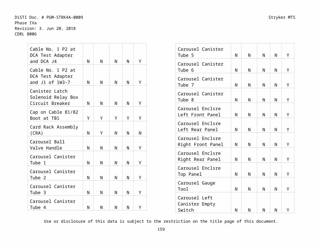
DiSTI Doc. # PGM-STRK4A-0009 Stryker MTS Phase IVaRevision: 3. Jun 20, 2018 CDRL B006
Transfer Case Upper Side Cover Y Y Y Y Y
Transmission ECU Y Y Y Y Y
Transmission Lift at First Axle Left Control Arm Y Y Y Y Y
Transmission Lift at First Axle Right Control Arm Y Y Y Y Y
Transmission Lift at First Differential Y Y Y Y Y
Transmission Lift at First Differential Y Y Y Y Y
Transmission Lift at Left Front Control Arm #1 Y Y Y Y Y
Transmission Lift at Right Front Control Arm #1 Y Y Y Y Y
Transmission Lift at Second Differential Y Y Y Y Y
Transmission Lift at Second Differential Y Y Y Y Y
Transmission Parking Brake Shoes Y Y Y Y Y
Transmission Parking Brake Springs Y Y Y Y Y
Transmission Shifter Display Y Y Y Y Y
Traverse Drive Brake Clutch N N N N Y
Traverse Drive Brake Clutch Ground Strap N N N N Y
Traverse Drive Clutch Connector N N N N Y
Traverse Drive FlexShaft Clamps N N N N Y
Traverse Drive Gear Box N N N N Y
Traverse Drive Gear Box Left Adjusting Ring N N N N Y
Traverse Drive Gear Box Left Adjusting Washer N N N N Y
Traverse Drive Gear Box Left Mounting Retainer N N N N Y
Traverse Drive Gear Box Right Adjusting Ring N N N N Y
Traverse Drive Gear Box Right Adjusting Washer N N N N Y
Traverse Drive Gear Box Right Mounting Retainer N N N N Y
Traverse Drive Gear Box Stand N N N N Y
Traverse Drive Gear Box Stand N N N N Y
Traverse Drive Handstation Connector N N N N Y
Traverse Drive Manual Handle N N N N Y
Use or disclosure of this data is subject to the restriction on the title page of this document.
160

DiSTI Doc. # PGM-STRK4A-0009 Stryker MTS Phase IVaRevision: 3. Jun 20, 2018 CDRL B006
Traverse Drive Manual Handle Left Button N N N N Y
Traverse Drive Manual Handle Right Button N N N N Y
Traverse Drive Manual Housing N N N N Y
Traverse Drive Motor N N N N Y
Traversing Gear Assembly N N Y N N
Troop Hatch Left Y Y Y Y N
Troop Hatch Right Y Y Y Y N
Troop Ventilation Fan (Rear Ventilation Fan) Y N N N N
TSEU Lower Bracket N N N N Y
TSEU Shock Mounts N N N N Y
TSEU Upper Bracket N N N N Y
Turbocharger Y Y Y Y Y
Turbocharger Air Inlet Tube Y Y Y Y Y
Turbocharger Coolant Return Tube Y Y Y Y Y
Turbocharger Coolant Supply Tube Y Y Y Y Y
Turbocharger Cooler Inlet Tube Y Y Y Y Y
Turbocharger Heat Shield Y Y Y Y Y
Turbocharger Inlet Elbow Y Y Y Y Y
Use or disclosure of this data is subject to the restriction on the title page of this document.
161

DiSTI Doc. # PGM-STRK4A-0009 Stryker MTS Phase IVaRevision: 3. Jun 20, 2018 CDRL B006
Turbocharger Oil Drain Tube Y Y Y Y Y
Turbocharger Oil Drain Tube Y Y Y Y Y
Turbocharger Oil Supply Tube Y Y Y Y Y
Turbocharger Oil Supply Tube (Elbow Connector) Y Y Y Y Y
Turbocharger Outlet Adapter Y Y Y Y Y
Turret N N N N Y
Turret Access Cover N N N N Y
Turret Auxiliary Switch Panel (TASP) N N N N Y
Turret Drive Lock N Y N N N
Turret Mounts N N N N Y
Turret Power Distribution Panel (TPDP) N N N N Y
Turret Power Distribution Panel (TPDP) N N N N Y
Turret Rope - Lanyard N N N N Y
Turret Sling N N N N Y
Turret Stand N N N N Y
Turret System Electronic Unit (TSEU) N N N N Y
Ultrasonic Leak Detector at Accessory Manifold Y Y Y Y Y
Ultrasonic Leak Detector at CTIS Manifold Y Y Y Y Y
Ultrasonic Leak Detector at LR 3 Brake Actuator Y Y Y Y Y
Ultrasonic Leak Detector at LR 3 Brake Hoses Y Y Y Y Y
Ultrasonic Leak Detector at LR 3 Strut Y Y Y Y Y
Ultrasonic Leak Detector at LR 3 Strut Chrg Fit Y Y Y Y Y
Ultrasonic Leak Detector at LR 4 Brake Actuator Y Y Y Y Y
Ultrasonic Leak Detector at LR 4 Brake Hoses Y Y Y Y Y
Ultrasonic Leak Detector at LR 4 Strut Y Y Y Y Y
Ultrasonic Leak Detector at LR 4 Strut Chrg Fit Y Y Y Y Y
Ultrasonic Leak Detector at Shft Cyl Blkhd Hoses Y Y Y Y Y
Ultrasonic Leak Detector at Shft Cyl Lwr Supply Hose Y Y Y Y Y
Ultrasonic Leak Detector at Shft Cyl Upr Supply Hose Y Y Y Y Y
Use or disclosure of this data is subject to the restriction on the title page of this document.
162

DiSTI Doc. # PGM-STRK4A-0009 Stryker MTS Phase IVaRevision: 3. Jun 20, 2018 CDRL B006
Ultrasonic Leak Detector at Tube P10 Y Y Y Y Y
Ultrasonic Leak Detector at Tube P6 Y Y Y Y Y
Ultrasonic Leak Detector at Tube P9 Y Y Y Y Y
Ultrasonic Leak Detector Power Switch Y Y Y Y Y
Universal Sight Electronic Unit (USEU) N N N N Y
Up/Left Button on VDT Y Y Y Y Y
Upper (Front Brake) Air Reservoir Drain Valve Y Y Y Y Y
Upper 4x8 Air Control Valve Manual Switch (4A) Y Y Y Y Y
Upper Forward Breech Access Cover N N N N Y
Upper Forward Door Hinge Bolts N N N N Y
Upper Fwd Door Shoulder Screws N N N N Y
Upper Hydraulic Inlet Hose Slip Ring Connector N N N N Y
Upper Hydraulic Outlet Hose Slip Ring Connector N N N N Y
Upper Left Light Transmitter N N N N Y
Upper Rear Cover N N N N Y
Upper Rear Door N N N N Y
Upper Rear Guard N N N N Y
Upper Rear Mid Access Cover N N N N Y
Upper Rear Mid Access Panel N N N N Y
Upper Rear Splice N N N N Y
Upper Rear Support N N N N Y
Upper Right Light Receiver N N N N Y
Upper Support N N N N Y
Upper Valve Closed Y Y Y Y Y
Upper Valve Closed Y Y Y Y Y
Upper Valve Open Y Y Y Y Y
Upper Valve Open Y Y Y Y Y
Upr Fwd Breech Access Frame N N N N Y
USEU Lower Bracket N N N N Y
USEU Shock Mounts N N N N Y
USEU Upper Bracket N N N N Y
Valve Cap and Nut Y Y Y Y Y
Valve Down Y Y Y Y N
VDT Event Code Y Y Y Y Y
VDT Event Code - HOT Y Y Y Y Y
Use or disclosure of this data is subject to the restriction on the title page of this document.
163

DiSTI Doc. # PGM-STRK4A-0009 Stryker MTS Phase IVaRevision: 3. Jun 20, 2018 CDRL B006
VDT Event Potential Sources Y Y Y Y Y
VDT Event Potential Sources - HOT Y Y Y Y Y
Use or disclosure of this data is subject to the restriction on the title page of this document.
164

DiSTI Doc. # PGM-STRK4A-0009 Stryker MTS Phase IVaRevision: 3. Jun 20, 2018 CDRL B006
VDT Event Subsystem Y Y Y Y Y
VDT Event Subsystem - HOT Y Y Y Y Y
VDT Fail Code Y Y Y Y Y
VDT Fail Code - HOT Y Y Y Y Y
VDT Fault Reported By Y Y Y Y Y
VDT Fault Reported By - HOT Y Y Y Y Y
Vehicle Power Conditioner (VPC) N N N Y N
Vent Fan J1 to Temp Switch Interface Plate N Y N N N
Vent Fan Switch LED Y Y Y Y Y
Video Display Terminal (VDT) Y Y Y Y Y
VIM Adjusting Screws Y N N N N
VIM Cover Plate Y N N N N
VIM installed Y N N N N
VIM lens cap Y N N N N
VIM Lens cap off Y N N N N
VIM Lens Cover Y N N N N
Visor for Thermal Imaging Module Y N N N N
Visual Imaging Module Y N N N N
Visual Imaging Module (VIM) Y N N N N
Voltage Regulator Y Y Y Y N
W1 Y N N N N
W13-P1 on RWS Assembly (Left) Y N N N N
W16 Y N N N N
W1-P2 of FFS Test Set to PDP-J6 Y Y Y Y Y
W1-P2 of FFS Test Set to PDP-J6 Y Y Y Y Y
W2 P1 Y N N N N
W200E-7 P1 N N N N Y
W200E-7 P2 N N N N Y
W201 P1 to PDA J3 N Y N N N
W201E-7 P1 N N N N Y
W201E-7 P2 N N N N Y
W202 P1 to BPS J1 N Y N N N
W202 P2 to PDA J1 N Y N N N
W202E-7 P1 N N N N Y
W202E-7 P2 N N N N Y
W203 P1 to PDA J2 N Y N N N
W203 P2 to BPS J2 N Y N N N
W203 P3 to SRA J2 N Y N N N
W203 P4 to SRA J3 N Y N N N
W203 P5 to CRA J1 N Y N N N
Use or disclosure of this data is subject to the restriction on the title page of this document.
165

DiSTI Doc. # PGM-STRK4A-0009 Stryker MTS Phase IVaRevision: 3. Jun 20, 2018 CDRL B006
W204 E1 N Y N N N
W204 E2 N Y N N N
W204 E3 N Y N N N
W204 E4 N Y N N N
W204 P1 to PDA J4 N Y N N N
W205 P1 to PDA J5 N Y N N N
W205 P2 to CCP J1 N Y N N N
W205 P3 to CRA J4 N Y N N N
W205 P4 to PEU J1 N Y N N N
W205 P5 to PTA J3 N Y N N N
W205 P6 to GDA J1 N Y N N N
W205 P7 to CRA J8 N Y N N N
W205A-7 P2 N N N N Y
W206 P3 N Y N N N
W207 P1 N Y N N N
W207 P3 to PTA J1 N Y N N N
W207 P4 to PTA J2 N Y N N N
W209 P1 to CRA J7 N Y N N N
W211 P1 to CRA J10 N Y N N N
W212 P1 to CRA J9 N Y N N N
W213 P1 to PEU J4 N Y N N N
W213 P2 to CRA J5 N Y N N N
W214 P1 to PEU J6 N Y N N N
Use or disclosure of this data is subject to the restriction on the title page of this document.
166

DiSTI Doc. # PGM-STRK4A-0009 Stryker MTS Phase IVaRevision: 3. Jun 20, 2018 CDRL B006
W214 P2 to Traverse Lower Drive Assembly N Y N N N
W214A-7 P2 N N N N Y
W214A-7 P3 N N N N Y
W215A-7 N N N N Y
W215A-7 P1 N N N N Y
W215A-7 P2 N N N N Y
W216 P1 to CRA J6 N Y N N N
W216 P2 to Gunner's Handle J1 N Y N N N
W216 P3 to APA J2 N Y N N N
W216 P4 to APA J1 N Y N N N
W216 P6 to LPA J1 N Y N N N
W217 P4 to SRA J4 N Y N N N
W218 P5 to SRA J5 N Y N N N
W222 P13 to SRA J13 N Y N N N
W222 P2 to Mast Lower Limit Switch N Y N N N
W224 J3 to Temp Switch Interface Plate N Y N N N
W224 P1 to W218 J1 N Y N N N
W224 P10 to FCS J1 N Y N N N
W224 P11 to TAS 3J1 N Y N N N
W224 P12 to Ballistic Door Actuator J1 N Y N N N
W224 P13 to TAS 3JX N Y N N N
W224 P2 to W217 J2 N Y N N N
W224 P4 to Temperature Switch J1 N Y N N N
W224 P5 to Gyro Assembly J1 N Y N N N
W224 P6 to TIA J1 N Y N N N
W224 P7 to TIA J2 N Y N N N
W224 P9 to FCS J4 N Y N N N
W225 P1 to TAS 3P1 N Y N N N
W225 P2 to Dual TOW Launcher J1 N Y N N N
W225 P3 to TIA J3 N Y N N N
W225 P4 to FCS J2 N Y N N N
W227 P1 to CRA J3 N Y N N N
W227 P2 to GPA J1 N Y N N N
W228 P1 to Grenade Discharger Bracket N Y N N N
W229 P1 to FCS J3 N Y N N N
W3 P1 Y N N N N
W3-P1 on RWS Assembly (Left) Y N N N N
W4 Y Y Y Y N
Use or disclosure of this data is subject to the restriction on the title page of this document.
167

DiSTI Doc. # PGM-STRK4A-0009 Stryker MTS Phase IVaRevision: 3. Jun 20, 2018 CDRL B006
W4 P6 Y Y Y Y Y
W401-7 P2 N N N N Y
W401-7 P4 N N N N Y
W402 P7 of Map Light Y N N N N
W402 P8 of Map Light Y N N N N
W412 P2 to Ration Warmer N N Y N N
W413 P1 to Ramp Control Box J1 Y Y Y Y N
W415 J1 Y Y Y Y Y
W415 P11 Y Y Y Y Y
W418 P1 Y Y Y Y Y
W418 P5 Y N N N N
W418 P6 Y Y Y Y N
W418A Y Y Y Y N
W418A P2 Y Y Y Y N
W418A P3 Y Y Y Y N
W418A P4 Y Y Y Y N
W421 P1 Y Y Y Y Y
W421 P3 Y Y Y Y Y
W425 P24 Y Y Y Y Y
W429 P1 Y Y Y Y Y
W433 P1 at PDP 2 Y Y Y Y Y
W433 P2 at PDP Y Y Y Y Y
W434 P1 Y Y Y Y Y
W436 E1 to Valve Simulators Y Y Y Y Y
W436 E1 to Valve Simulators Y Y Y Y Y
W436 E2 to Valve Simulators Y Y Y Y Y
W436 E2 to Valve Simulators Y Y Y Y Y
W436 E3 to Valve Simulators Y Y Y Y Y
W436 E3 to Valve Simulators Y Y Y Y Y
W436 E7 to Fire Extinguisher E7 Y Y Y Y Y
W436 E7 to Valve Simulators Y Y Y Y Y
W436 E7 to Valve Simulators Y Y Y Y Y
W436 E8 to Valve Simulators Y Y Y Y Y
W436 E8 to Valve Simulators Y Y Y Y Y
W441 P1 Y Y Y Y Y
W441 P8 at Oil Pressure Transmitter Y Y Y Y Y
Use or disclosure of this data is subject to the restriction on the title page of this document.
168

DiSTI Doc. # PGM-STRK4A-0009 Stryker MTS Phase IVaRevision: 3. Jun 20, 2018 CDRL B006
W441 P9 at Oil Pressure Switch Y Y Y Y Y
W442 P1 Y Y Y Y Y
Use or disclosure of this data is subject to the restriction on the title page of this document.
169

DiSTI Doc. # PGM-STRK4A-0009 Stryker MTS Phase IVaRevision: 3. Jun 20, 2018 CDRL B006
W442 P10 Y Y Y Y Y
W442 P11 Y Y Y Y Y
W443 P1 Y Y Y Y Y
W451 Y Y Y Y N
W451 Y Y Y Y N
W451 Y Y Y Y N
W457 P2 to CRA J2 N Y N N N
W459 Y Y Y Y Y
W459 Y Y Y Y Y
W459 Y Y Y Y Y
W4-7 P2 N N N N Y
W4A-7 P2 N N N N Y
W504 J1 Cap Y Y Y Y Y
W531E-7 P1 N N N N Y
W531E-7 P2 N N N N Y
W555E-7 P1 N N N N Y
W555E-7 P2 N N N N Y
W6_P2 connected/disconnected to 8J1 Y N N N N
W74R-P2 of RF Control Arm #1 Y Y Y Y Y
W8 P1 Y N N N N
W8_P1 connected/disconnected to 3J3 Y N N N N
W9 P1 Y N N N N
W9-P1 On RWS Assembly (Left) Y N N N N
Water Pump Y Y Y Y Y
Water Pump Belt Y Y Y Y Y
Water Pump Drive Pulley Y Y Y Y Y
Water Pump Idler Pulley Y Y Y Y Y
Water Pump Idler Pulley Cover Y Y Y Y Y
Water Pump Outlet Tee Fitting Y Y Y Y Y
Water Pump Return Hose Y Y Y Y Y
Water Pump Supply Hose Y Y Y Y Y
Water Pump to Surge Tank Hose Y Y Y Y Y
Wheel Chock (left rear left) Y Y Y Y Y
Wheel Chock (left rear right) Y Y Y Y Y
Wheel Chock (right rear left) Y Y Y Y Y
Wheel Chock (right rear right) Y Y Y Y Y
Wheel Chocks Y Y Y Y Y
Use or disclosure of this data is subject to the restriction on the title page of this document.
170
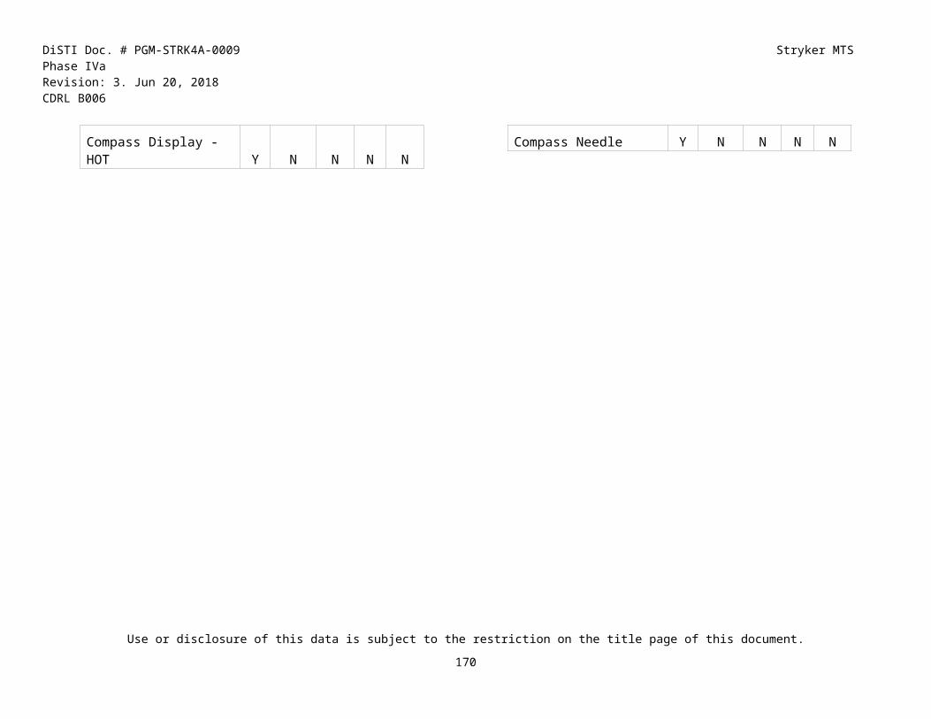
DiSTI Doc. # PGM-STRK4A-0009 Stryker MTS Phase IVaRevision: 3. Jun 20, 2018 CDRL B006
Winch Hydraulic Drain Hose Quick-Disconnect Y Y Y Y Y
Winch Hydraulic Pressure Hose Quick-Disconnect Y Y Y Y Y
Winch Hydraulic Return Hose Quick-Disconnect Y Y Y Y Y
Winch Load-Sensing Hose Quick-Disconnect Y Y Y Y Y
Wiring Harness Interconnect Brckt N N N N Y
Wiring Harness SW2378 N N N N Y
Wiring Harness W224 N Y N N N
Wiring Harness W224 N Y N N N
Wood Blocks (Cannon) N N N N Y
Wood Blocks (Recoil) N N N N Y
Use or disclosure of this data is subject to the restriction on the title page of this document.
171

DiSTI Doc. # PGM-STRK4A-0009 Stryker MTS Phase IVaRevision: 3. Jun 20, 2018 CDRL B006
APPENDIX E BUTTON TASKSThis section contains the tasks that are accomplished by a single virtual action. They are referred to as “Button Tasks”. The IETM Step Reference and Usual Result provide an example of the step text that would be displayed in the applicable IAV or MGS IETM when use of the Button Task would be indicated, and the resulting change in the Virtual Environment when the Button Task is performed.
Button Task IETM Step Reference Usual Result ICV RWS ATGM FSV MCV MGS105mm Cannon and Recoil Mechanism Removed
Condition - 105mm Cannon and Recoil Mechanism Removed
- 105mm Main Cannon removed and placed on wood blocks- Recoil Mechanism removed and placed on wood blocks- Gun Pod Armor removed to allow access to Main Cannon- CPV Deployed- Wiring Harnesses 1W215B-7 P2, 1W215B-7 P3, 1W105D-7 P3 disconnected.
N N N N N Y
Adjust Brake Shoes on Right Front #1 Wheel
Adjust Brake Shoes. Brake shoes adjusted on right front #1 wheel.
Y N N N N N
Adjust collimator (MRS) rear cell
Adjust collimator (MRS) rear cell Collimator (MRS) rear cell adjusted.
N N N N N Y
Adjust Parking Brake Parking Brake Adjustment The parking brake has been adjusted.
Y N N N N N
Adjust Three STORM LRF Bracket Adapters
Adjust three STORM LRF bracket adapters until laser dot appears near STORM aiming mark on 15 m boresighting target board.
Adjustment of three STORM LRF bracket adapters until laser dot appears near STORM aiming mark on 15 m boresighting target board has been performed.
N Y N N N N
ALC CAUTION Message Not Displayed on Central Control Panel
ALC CAUTION Message Not Displayed on Central Control Panel
The "ALC CAUTION Message Not Displayed on Central Control Panel" equipment condition has been completed.
N N N N N Y
Use or disclosure of this data is subject to the restriction on the title page of this document.
172

DiSTI Doc. # PGM-STRK4A-0009 Stryker MTS Phase IVaRevision: 3. Jun 20, 2018 CDRL B006
Button Task IETM Step Reference Usual Result ICV RWS ATGM FSV MCV MGSAttempt to update Muzzle Reference Sensor (MRS)
Attempt to update Muzzle Reference Sensor (MRS)
Attempt to update Muzzle Reference Sensor (MRS) made.
N N N N N Y
Automatic Fire Extinguishing System (AFES) Safeguards Engaged
Automatic Fire Extinguishing System (AFES) Safeguards Engaged
Automatic Fire Extinguishing System (AFES) Safeguards Engaged
Y N N N N N
Battery Power Source (BPS) Power-Up
Battery Power Source (BPS) Power-Up Battery Power Source (BPS) Powered Up
N N Y N N N
Bleed turret hydraulic distribution lines
Bleed turret hydraulic distribution lines Turret hydraulic distribution lines bled.
N N N N N Y
Bleed upper gun pod hydraulic system
Bleed upper gun pod hydraulic system Upper gun pod hydraulic system bled.
N N N N N Y
Boresight mobile gun system
Boresight mobile gun system Mobile gun system boresighted.
N N N N N Y
Boresight Target Acquisition System
Boresight Target Acquisition System Boresight Target Acquisition System was performed
N N Y N N N
Cable Assembly 2 Inspection
Inspect Connectors and All Exposed Portions of Cable Assembly 2 for Damage.
Cable Assembly 2 Inspected for Damage and Passed.
Y N N N N N
Cable Assembly 2A Inspection
Inspect Connectors and All Exposed Portions of Cable Assembly 2A for Damage.
Cable Assembly 2A Inspected for Damage and Passed.
Y N N N N N
Cable Assembly 3A1 Inspection
Inspect Connectors and All Exposed Portions of Cable Assembly 3A1 for Damage.
Cable Assembly 3A1 Inspected for Damage and Passed.
Y N N N N N
Cable Assembly 3A2 Inspection
Inspect Connectors and All Exposed Portions of Cable Assembly 3A2 for Damage.
Cable Assembly 3A2 Inspected for Damage and Passed.
Y N N N N N
Cable Assembly 4A Inspection
Inspect connectors and exposed portions of cable assembly 4A for damage.
Cable Assembly 4A Inspected for Damage and Passed.
Y N N N N N
Cable Assembly 4B Inspection
Inspect connectors and exposed portions of cable assembly 4B for damage.
Cable Assembly 4B Inspected for Damage and Passed.
Y N N N N N
Use or disclosure of this data is subject to the restriction on the title page of this document.
173

DiSTI Doc. # PGM-STRK4A-0009 Stryker MTS Phase IVaRevision: 3. Jun 20, 2018 CDRL B006
Button Task IETM Step Reference Usual Result ICV RWS ATGM FSV MCV MGSCable Assembly 5 Inspection
- Inspect connectors and exposed portions of cable assembly 5 for damage.- Check contacts at cable assembly 5 and main ground terminal block for loose or dirty connection.- Check contacts at cable assembly 5 and main ground terminal block for corrosion.
Cable Assembly 5 Inspected.- No damage found.- No loose or dirty connections found.- No corrosion found.
Y N N N N N
Cable Assembly 5A Inspection
- Inspect connectors and exposed portions of cable assembly 5A for damage.- Check contacts at cable assembly 5A and main ground terminal block for loose or dirty connection.- Check contacts at cable assembly 5A and main ground terminal block for corrosion
Cable Assembly 5A Inspected.- No damage found.- No loose or dirty connections found.- No corrosion found.
Y N N N N N
Cable Assembly 5B Inspection
Inspect connectors and exposed portions of cable assembly 5B for damage.
Cable Assembly 5B Inspected for Damage and Passed.
Y N N N N N
Cable Assembly 5C Inspection
- Inspect connectors and exposed portions of cable assembly 5C for damage.- Check contacts at cable assembly 5C and main ground terminal block for loose or dirty connection.- Check contacts at cable assembly 5C and main ground terminal block for corrosion
Cable Assembly 5C Inspected.- No damage found.- No loose or dirty connections found.- No corrosion found.
Y N N N N N
Cable Assembly 5D Inspection
Inspect connectors and exposed portions of cable assembly 5D for damage.
Cable Assembly 5D Inspected for Damage and Passed.
Y N N N N N
Cable Assembly 67 Inspection
Inspect connectors and exposed portions of cable assembly 67 for damage.
Cable Assembly 67 Inspected for Damage and Passed.
Y N N N N N
Cable Assembly 68 Inspection
Inspect connectors and exposed portions of cable assembly 68 for damage.
Cable Assembly 68 Inspected for Damage and Passed.
Y N N N N N
Use or disclosure of this data is subject to the restriction on the title page of this document.
174

DiSTI Doc. # PGM-STRK4A-0009 Stryker MTS Phase IVaRevision: 3. Jun 20, 2018 CDRL B006
Button Task IETM Step Reference Usual Result ICV RWS ATGM FSV MCV MGSCable Assembly 6A Inspection
Inspect connectors and exposed portions of cable assembly 6A for damage.
Cable Assembly 6A Inspected for Damage and Passed.
Y N N N N N
Cable Assembly 6B Inspection
Inspect connectors and exposed portions of cable assembly 6B for damage.
Cable Assembly 6B Inspected for Damage and Passed.
Y N N N N N
Cable Assembly 81 Inspection
Inspect Connectors and All Exposed Portions of Cable Assembly 81 for Damage.
Cable Assembly 81 Inspected for Damage and Passed.
Y N N N N N
Cable Assembly 82 Inspection
Inspect Connectors and All Exposed Portions of Cable Assembly 82 for Damage.
Cable Assembly 82 Inspected for Damage and Passed.
Y N N N N N
Calibrate Thrust Piece 1) Placed leads of digital multimeter on pins A and B of sensor connector.2) Adjusted thrust piece on rear end of control arm by turning bolt and nut to left or right to obtain a resistance value of 840-880 ohms at the sensor's connector.3) Positioned c
Thrust Piece Calibration Successful
Y N N N N N
Cannon Installation Step 2. Lift cannon to recoil mechanism and install cannon up to breech
Installation Step 2. Lift cannon to recoil mechanism and install cannon up to breech, repositioning sling around recoil mechanism at end of cannon.
- Cannon lifted to recoil mechanism- Cannon installed up to breech- Sling repositioned around recoil mechanism at end of cannon
N N N N N Y
Cannon Installation Step 2. Lift cannon to recoil mechanism and install cannon up to breech with Replacement
Installation Step 2. Lift cannon to recoil mechanism and install cannon up to breech, repositioning sling around recoil mechanism at end of cannon.
- Cannon and recoil mechanism replaced- Cannon lifted to recoil mechanism- Cannon installed up to breech- Sling repositioned around recoil mechanism at end of cannon
N N N N N Y
Use or disclosure of this data is subject to the restriction on the title page of this document.
175

DiSTI Doc. # PGM-STRK4A-0009 Stryker MTS Phase IVaRevision: 3. Jun 20, 2018 CDRL B006
Button Task IETM Step Reference Usual Result ICV RWS ATGM FSV MCV MGSCannon Installation Step 28. Using suitable lifting device, raise cannon and slowly guide into gun pod
Installation Step 28. Using suitable lifting device, raise cannon and slowly guide into gun pod, aligning recoil rails with gun pod rails.
- Cannon replaced- Cannon raised and slowly guided into gun pod- Recoil rails aligned with gun pod rails
N N N N N Y
Cannon Installation Step 29. Continue sliding cannon, engaging recoil rails with gun pod rails, maintaining alignment of cannon in gun pod.
Installation Step 29. Continue sliding cannon, engaging recoil rails with gun pod rails, maintaining alignment of cannon in gun pod.
- Cannon slid, engaged recoil rails with gun pod rails- Alignment of cannon in gun pod maintained
N N N N N Y
Cannon Installation Step 33. Move cannon into gun pod until breech is approximately 25 inches from front of gun pod chamber
Installation Step 33. Move cannon into gun pod until breech is approximately 25 inches from front of gun pod chamber.
- Cannon moved into gun pod until breech is approximately 25 inches from front of gun pod chamber- Endless nylon web sling removed
N N N N N Y
Cannon Removal Step 32. Continue to move cannon out of gun pod until recoil mechanism is fully exposed
Removal Step 32. Continue to move cannon out of gun pod until recoil mechanism is fully exposed. Reposition sling around recoil mechanism, 38 inches from rear of recoil mechanism from rear of gun assembly.
- Cannon moved out of gun pod, recoil mechanism is fully exposed.- Sling repositioned around recoil mechanism, 38 inches from rear of recoil mechanism from rear of gun assembly.
N N N N N Y
Cannon Removal Step 34. Continue to move cannon out of gun pod using sling, lanyard and suitable lifting device until cannon clears gun pod
Removal Step 34. Continue to move cannon out of gun pod using sling, lanyard and suitable lifting device until cannon clears gun pod.
- Cannon moved out of gun pod using sling, lanyard and suitable lifting device; cannon cleared gun pod.- Breech Support Tool removed.- In Battery Come Along removed.- Gun In/Out of Battery Tool removed.
N N N N N Y
Use or disclosure of this data is subject to the restriction on the title page of this document.
176

DiSTI Doc. # PGM-STRK4A-0009 Stryker MTS Phase IVaRevision: 3. Jun 20, 2018 CDRL B006
Button Task IETM Step Reference Usual Result ICV RWS ATGM FSV MCV MGSCannon Removal Step 35. Lower cannon onto two wood blocks. Remove lanyards.
Cannon Removal Step 35. Lower cannon onto two wood blocks. Remove lanyards.
- Two wood blocks installed.- Cannon lowered onto two wood blocks.- Lanyards removed.
N N N N N Y
Cannon Removal Step 43. Pull recoil mechanism away from breech and clear cannon. Lower recoil mechanism onto two wood blocks.
Removal Step 43. Pull recoil mechanism away from breech and clear cannon. Lower recoil mechanism onto two wood blocks.
- Recoil mechanism pulled away from breech and cleared cannon.- Recoil mechanism lowered onto two wood blocks.
N N N N N Y
Center main gun over front deck and near 0 degrees elevation using CCH with Power Up Commander's Station
Center main gun over front deck and near 0 degrees elevation using CCH with Power Up Commander's Station
Main gun centered over front deck and near 0 degrees elevation using CCH with Commander's Station Powered Up
N N N N N Y
Center main gun over front deck and near 0 degrees elevation using CCH without Power Up Commander's Station
Center main gun over front deck and near 0 degrees elevation using CCH
Main gun centered over front deck and near 0 degrees elevation using CCH
N N N N N Y
Center main gun over front deck and near 0 degrees elevation using GCH with Power Up Commander's Station
Center main gun over front deck and near 0 degrees elevation using GCH with Power Up Commander's Station
Main gun centered over front deck and near 0 degrees elevation using GCH with Commander's Station Powered Up
N N N N N Y
Center main gun over front deck and near 0 degrees elevation using GCH without Power Up Commander's Station
Center main gun over front deck and near 0 degrees elevation using GCH
Main gun centered over front deck and near 0 degrees elevation using GCH
N N N N N Y
Center main gun over left side hatch using CCH with Power Up Commander's Station
Center main gun over left side hatch using CCH with Power Up Commander's Station
Main gun centered over left side hatch using CCH with Commander's Station Powered Up
N N N N N Y
Use or disclosure of this data is subject to the restriction on the title page of this document.
177

DiSTI Doc. # PGM-STRK4A-0009 Stryker MTS Phase IVaRevision: 3. Jun 20, 2018 CDRL B006
Button Task IETM Step Reference Usual Result ICV RWS ATGM FSV MCV MGSCenter main gun over left side hatch using CCH without Power Up Commander's Station
Center main gun over left side hatch using CCH
Main gun centered over left side hatch using CCH
N N N N N Y
Center main gun over left side hatch using GCH with Power Up Commander's Station
Center main gun over left side hatch using GCH with Power Up Commander's Station
Main gun centered over left side hatch using GCH with Commander's Station Powered Up
N N N N N Y
Center main gun over left side hatch using GCH without Power Up Commander's Station
Center main gun over left side hatch using GCH
Main gun centered over left side hatch using GCH
N N N N N Y
Central Control Panel Display or Display Pushbutton Does Not Operate Properly Troubleshooting Completed
Central Control Panel Display or Display Pushbutton Does Not Operate Properly Troubleshooting Completed
The "Central Control Panel Display or Display Pushbutton Does Not Operate Properly" equipment condition has been completed.
N N N N N Y
Change breech round type to EMPTY
Change breech round type to EMPTY Breech round type changed to EMPTY
N N N N N Y
Charge A/C 2 system with 2.5 lb of R-134 refrigerant
- Using charging station, evacuate A/C 2 system and monitor vacuum for 15 minutes.- If A/C 2 system does not maintain vacuum or leak is found, refer to A/C system troubleshooting.- Using oil injection bottle on charging station, adjust level of R-134
- Quick-disconnect valves opened.- A/C 2 system charged with 2.5 lb of R-134 refrigerant.
Y N N N N N
Charge Pneumatic System Charge Pneumatic System Engine started and Pneumatic System charged.
Y N N N N N
Check elevation drive motor potentiometer for damage
Check elevation drive motor potentiometer for damage
Elevation drive motor potentiometer inspected. No damage found.
N N N N N Y
Use or disclosure of this data is subject to the restriction on the title page of this document.
178

DiSTI Doc. # PGM-STRK4A-0009 Stryker MTS Phase IVaRevision: 3. Jun 20, 2018 CDRL B006
Button Task IETM Step Reference Usual Result ICV RWS ATGM FSV MCV MGSCheck Engine Oil for Coolant Contamination
Check engine oil for coolant contamination
Engine oil checked for coolant contamination. No contamination found.
Y N N N N N
Check Engine Oil for Fuel Contamination
Check engine oil for fuel contamination Engine oil checked for fuel contamination. No contamination found.
Y N N N N N
Check Engine Oil Level Check engine oil Engine oil level checked. Oil level is not low.
Y N N N N N
Check if breech open sensor 1W2S411-7 is damaged/dirty
Check if breech open sensor 1W2S411-7 is damaged/dirty
Breech open sensor 1W2S411-7 inspected. No damage/dirt found.
N N N N N Y
Check if canister erect sensor 1W2S413-7 is damaged
Check if canister erect sensor 1W2S413-7 is damaged
Canister erect sensor 1W2S413-7 inspected. No damage found.
N N N N N Y
Check if canister stowed sensor W1F2134 is damaged
Check if canister stowed sensor W1F2134 is damaged
- Top canister freed from carousel, raised and secured with rope to V-block- Canister stowed sensor W1F2134 checked for damaged. No damage found.- After inspection, canister stowed and latched
N N N N N Y
Check if round in canister sensor 1W2S414-7 is damaged/dirty
Check if round in canister sensor 1W2S414-7 is damaged/dirty
Round in canister sensor 1W2S414-7 is inspected. No damage/dirt found.
N N N N N Y
Chock Wheels Chock Wheels Wheel chocks were inserted. Y Y Y Y Y YClear M2 .50 Caliber Machine Gun
Clear M2 .50 caliber machine gun. Refer to TM 9-1005-213-10.
M2 .50 caliber machine gun cleared.
N Y N N N N
Clear MK 19 40-mm Grenade Machine Gun
Clear MK 19 40-mm grenade machine gun. Refer to TM 9-1010-230-10.
MK 19 40-mm grenade machine gun cleared.
N Y N N N N
Use or disclosure of this data is subject to the restriction on the title page of this document.
179

DiSTI Doc. # PGM-STRK4A-0009 Stryker MTS Phase IVaRevision: 3. Jun 20, 2018 CDRL B006
Button Task IETM Step Reference Usual Result ICV RWS ATGM FSV MCV MGSCMS Sight Body and Modular Control Panel (MCP): Install new CMS Sight Body and MCP in vehicle
CMS Sight Body: Install new CMS Sight Body in vehicle
New CMS Sight Body installed in vehicle
N N N N N Y
CMS Sight Body and Modular Control Panel (MCP): Move to workbench
CMS Sight Body: Move to workbench CMS Sight Body moved to workbench
N N N N N Y
Coaxial Machine Gun Does Not Operate Properly Troubleshooting Completed
Coaxial Machine Gun Does Not Operate Properly Troubleshooting Completed
The "Coaxial Machine Gun Does Not Operate Properly" equipment condition has been completed.
N N N N N Y
Commander's Panoramic Viewer Does Not Operate Properly Troubleshooting Completed For Fault 1579
Commander's Panoramic Viewer Does Not Operate Properly Troubleshooting Completed
Troubleshooting steps performed. The vehicle is in the following state:
- CPV Access Door is open- Right Pan Viewer Top Door is open- CPV is deployed- Commander's Station and Turret are powered down
N N N N N Y
Commander's Panoramic Viewer Does Not Operate Properly Troubleshooting Completed For Faults 1574 and 1575
Commander's Panoramic Viewer Does Not Operate Properly Troubleshooting Completed
Troubleshooting steps performed. The vehicle is in the following state:
- CPV Access Door is open- Right Pan Viewer Top Door is open- CPV position is unchanged- Commander's Station and Turret are powered down
N N N N N Y
Use or disclosure of this data is subject to the restriction on the title page of this document.
180

DiSTI Doc. # PGM-STRK4A-0009 Stryker MTS Phase IVaRevision: 3. Jun 20, 2018 CDRL B006
Button Task IETM Step Reference Usual Result ICV RWS ATGM FSV MCV MGSCommander's Panoramic Viewer Does Not Operate Properly Troubleshooting Completed%For Faults 1577 and 1578
Commander's Panoramic Viewer Does Not Operate Properly Troubleshooting Completed
Troubleshooting steps performed. The vehicle is in the following state:
- CPV Access Door is open- Right Pan Viewer Top Door is open- CPV is deployed- Commander's Station and Turret are powered down
N N N N N Y
Connect Battery Ground Connect Battery Ground Battery Ground Connected N N N N N YConnect Battery Ground Connect Battery Ground Battery Ground connected Y N N N N NConnect Power Pack Run-Up Kit
Connect Power Pack Run-Up Kit Power Pack Run-Up Kit connected
Y N N N N N
Control Electronics Panel Self-Test Performed
Control Electronics Panel Self-Test Performed
Control Electronics Panel Self-Test Performed
Y N N N N N
CPV - Lower CPV into storage compartment
Lower CPV into storage compartment CPV lowered into storage compartment
N N N N N Y
CPV - Remove CPV from vehicle and place on a suitable working surface.
Remove CPV from vehicle and place on a suitable working surface.
CPV removed from vehicle and placed on Workbench.
N N N N N Y
CPV - Slowly lift CPV from stand and position over gun pod
Slowly lift CPV from stand and position over gun pod
- CPV replaced- CPV lifted from stand and positioned over gun pod.
N N N N N Y
CPV - Slowly remove CPV from gun pod
Slowly remove CPV from gun pod CPV removed slowly from gun pd.
N N N N N Y
Disconnect Battery Ground Disconnect Battery Ground Battery Ground Disconnected Y N N N N NDisconnect Battery Ground Disconnect Battery Ground Battery Ground Disconnected N N N N N YDisconnect Power Pack Run-Up Kit
Disconnect Power Pack Run-Up Kit Power Pack Run-Up Kit disconnected
Y N N N N N
Disengage Automatic Fire Extinguishing System (AFES) Safeguards
Disengage AFES safeguards AFES safeguards disengaged Y N N N N N
Use or disclosure of this data is subject to the restriction on the title page of this document.
181

DiSTI Doc. # PGM-STRK4A-0009 Stryker MTS Phase IVaRevision: 3. Jun 20, 2018 CDRL B006
Button Task IETM Step Reference Usual Result ICV RWS ATGM FSV MCV MGSDownload Turret Line Replacement Units (LRU) Software using MGS LRU Programmer
Download Turret Line Replacement Units (LRU) Software using MGS LRU Programmer
Turret Line Replacement Units (LRU) Software Downloaded using MGS LRU Programmer.
N N N N N Y
Download vehicle system software using Software Loader Verifier
Download vehicle system software using Software Loader Verifier
Vehicle System Software downloaded using Software Loader Verifier.
N N N N N Y
Drain Air Reservoirs Drain Air Reservoirs Air Reservoirs Drained Y N N N N NDrain Cooling System Drain cooling system. Cooling system drained. Y N N N N NDrain First Differential Gearbox Assembly
First Differential Gearbox Assembly Drained
First Differential Gearbox Assembly Drained.
Y N N N N N
Drain Fuel Sample From Primary Fuel Filter/Separator and Check for Contamination.
Drain fuel sample from primary fuel filter/separator and check for contamination.
The Drain Fuel/Water Separator task was performed. The fuel was not contaminated.
Y N N N N N
Drain Fuel Tanks Drain Fuel Tanks Part a, Drain, of the Drain/Fill Fuel Tanks task has been performed.
Y N N N N N
Drain HMS Manifold Drain Height Management System Manifold.
Height Management System Manifold drained.
Y N N N N N
Drain Hydraulic Reservoir (Power Pack Installed)
Drain Hydraulic Reservoir (Power Pack Installed)
Hydraulic Fluid Drained From Reservoir.
Y N N N N N
Driver's Seat Assembly - Lift out of hull
With assistance of second person, and using lifting device, lift driver's seat assembly (2) out of hull.
Driver's seat assembly lifted out of hull.
Y N N N N N
Driver's Seat Assembly - Position in hull
3. With assistance of second person, and using suitable lifting device, position driver's seat assembly in hull.
Driver's seat assembly positioned in hull.
Y N N N N N
Ensure autoloader inventory is correct
Ensure autoloader inventory is correct Autoloader inventory is correct.
N N N N N Y
Ensure breech is empty Ensure breech is empty The breech is empty. N N N N N YEnsure breech round type is empty
Ensure breech round type is empty Breech round type is empty N N N N N Y
Use or disclosure of this data is subject to the restriction on the title page of this document.
182

DiSTI Doc. # PGM-STRK4A-0009 Stryker MTS Phase IVaRevision: 3. Jun 20, 2018 CDRL B006
Button Task IETM Step Reference Usual Result ICV RWS ATGM FSV MCV MGSEnsure breech round type is HEP
Ensure breech round type is HEP Breech round type is HEP N N N N N Y
Ensure carousel inventory is clear
Ensure carousel inventory is clear Carousel inventory has been checked and is clear.
N N N N N Y
Ensure carousel top canister is fully stowed and latched
Ensure carousel top canister is fully stowed and latched
Carousel top canister is fully stowed and latched
N N N N N Y
Ensure chamber is free of foreign objects
Ensure chamber is free of foreign objects The chamber is free of foreign objects.
N N N N N Y
Ensure main gun is clear Ensure main gun is clear The main gun is clear. N N N N N YEnsure rammer is empty Ensure rammer is empty The rammer is empty. N N N N N YEnsure replenisher inventory is correct
Ensure replenisher inventory is correct Replenisher inventory is correct.
N N N N N Y
Ensure smoke grenade launchers are clear
Ensure smoke grenade launchers are clear
Smoke grenade launchers are clear.
N N N N N Y
Ensure that ETS platform is at 0 degrees azimuth and 0 degrees elevation
Ensure that ETS platform is at 0 degrees azimuth and 0 degrees elevation
ETS platform positioned at 0 degrees azimuth and 0 degrees elevation
N N Y N N N
Ensure that primary weapon and primary solenoid are installed
Ensure the primary weapon and primary solenoid are installed.
Primary weapon and primary solenoid are installed.
N Y N N N N
Ensure top canister is empty
Ensure top canister is empty The top canister is empty. N N N N N Y
Fill / Add Coolant to Cooling System
Coolant added to Cooling System Cooling System filled to proper level.
Y N Y N N N
Fill / Add Engine Oil Fill engine oil and check for proper levels.
Engine oil filled to proper levels
Y N N N N N
Fill First Differential Gearbox Assembly
First Differential Gearbox Assembly Filled.
First Differential Gearbox Assembly Filled.
Y N N N N N
Fill Hydraulic Reservoir (Power Pack Installed)
Fill Hydraulic Reservoir (Power Pack Installed)
Hydraulic Reservoir Filled. Y N N N N N
Fill Recuperator Assembly with Fire Retardant Hydraulic Oil
Fill Recuperator assembly with fire retardant hydraulic oil.
Recuperator assembly filled with fire retardant hydraulic oil.
N N N N Y N
Use or disclosure of this data is subject to the restriction on the title page of this document.
183

DiSTI Doc. # PGM-STRK4A-0009 Stryker MTS Phase IVaRevision: 3. Jun 20, 2018 CDRL B006
Button Task IETM Step Reference Usual Result ICV RWS ATGM FSV MCV MGSFlush Fuel System Flush Fuel System The Fuel System Flush task
has been performed.Y N N N N N
Flush Transfer Case Oil Cooler
Flush transfer case oil cooler. Transfer case oil cooler flushed.
Y N N N N N
Gun Pod (Right) Rear Plate Assembly Removed
Gun Pod (Right) Rear Plate Assembly Removed
The Gun Pod (Right) Rear Plate Assembly was removed. The following was also removed:
- CPV Access Door is removed- Right Pan Viewer Top Door is removed- Right Pan Viewer Top Cover is removed
N N N N N Y
Hand passed in front of Lower Left Receiver
Hand passed in front of Lower Left Receiver
Hand passed in front of Lower Left Receiver
N N N N N Y
Hand passed in front of Upper Left Transmitter
Hand passed in front of Upper Left Transmitter
Hand passed in front of Upper Left Transmitter.
N N N N N Y
Hand removed from in front of Lower Left Receiver
Hand removed from in front of Lower Left Receiver
Hand removed from in front of Lower Left Receiver
N N N N N Y
Hand removed from in front of Upper Left Transmitter
Hand removed from in front of Upper Left Transmitter
Hand removed from in front of Upper Left Transmitter
N N N N N Y
Height Management System Calibration
Calibrate Height Management System. Height Management System Calibration performed.
Y N N N N N
HMS Calibration Drive Vehicle 2 to 3 Feet Forward and Rearward Three Times
Drive vehicle 2-3 ft. forward and rearward three times to overcome effects of sticking in hydropneumatic struts.
Vehicle Driven. Y N N N N N
Use or disclosure of this data is subject to the restriction on the title page of this document.
184

DiSTI Doc. # PGM-STRK4A-0009 Stryker MTS Phase IVaRevision: 3. Jun 20, 2018 CDRL B006
Button Task IETM Step Reference Usual Result ICV RWS ATGM FSV MCV MGSHTPS CAUTION Message Appears On Central Control Panel Troubleshooting Completed
HTPS CAUTION Message Appears On Central Control Panel Troubleshooting Completed
HTPS CAUTION Message Appears On Central Control Panel Troubleshooting Completed
N N N N N Y
Hull/turret position sensor (HTPS) alignment
Hull/turret position sensor (HTPS) alignment
Aligned Hull/turret position sensor (HTPS).
N N N N N Y
Inspect breech closed sensor 1W2S410-7 for damage
Inspect breech closed sensor 1W2S410-7 for damage
Breech closed sensor 1W2S410-7 inspected. No damage found.
N N N N N Y
Inspect breech open sensor 1W2S411-7 for damage
Inspect breech open sensor 1W2S411-7 for damage
Breech open sensor 1W2S411-7 inspected. No damage found.
N N N N N Y
Inspect Engine Compartment Fan Hydraulic Components and Hoses
Check engine compartment fan hydraulic components and hoses for signs of kinks or hydraulic fluid leakage.
No signs of kinks or hydraulic fluid leakage was found.
Y N N N N N
Inspect Engine Compartment Fuel Lines
Inspect engine and all exposed portions of fuel lines in engine compartment for leaks, fuel accumulation in engine compartment or excessive fuel smell.
Engine and all exposed portions of fuel lines in engine compartment inspected for leaks, fuel accumulation in engine compartment or excessive fuel smell. None found.
Y N N N N N
Inspect gun in battery sensor 1W2S412-7 for damage
Inspect gun in battery sensor 1W2S412-7 for damage
Gun in battery sensor 1W2S412-7 inspected. No damage found.
N N N N N Y
Inspect main gun, turret, turret basket, and race ring for obstructions
Inspect main gun, turret, turret basket, and race ring for obstructions
Main gun, turret, turret basket, and race ring inspected for obstructions. None found.
N N N N N Y
Inspect turret race ring teeth for gouges, breaks, or flat spots
Inspect turret race ring teeth for gouges, breaks, or flat spots
Turret race ring teeth inspected for gouges, breaks, or flat spots. None found.
N N N N N Y
Use or disclosure of this data is subject to the restriction on the title page of this document.
185

DiSTI Doc. # PGM-STRK4A-0009 Stryker MTS Phase IVaRevision: 3. Jun 20, 2018 CDRL B006
Button Task IETM Step Reference Usual Result ICV RWS ATGM FSV MCV MGSInspect/add hydraulic fluid Inspect/add hydraulic fluid Hydraulic fluid inspected and
added.Y N N N N Y
Inspect/Add Transfer Case Oil
Inspect/Add Transfer Case Oil Oil at full mark. No leaks detected.
Y N N N N N
Install 105mm Cannon and Recoil Mechanism
Install 105mm Cannon and Recoil Mechanism
- Recoil Mechanism Installed on cannon- 105mm Cannon Installed in vehicle- Gun Pod Armor installed- CPV Stowed- Wiring Harnessed 1W215B-7 P2, 1W215B-7 P3, 1W105D-7 P3 connected.
N N N N N Y
Install Air Inlet Diffuser Install air inlet diffuser. Air inlet diffuser installed. Y N N N N NInstall Alternator using suitable lifting device and with assistance of second person
Using suitable lifting device and with assistance of second person, align alternator with lower alternator bracket.
- Woodruff key, alternator pulley, spring wather, and nut installed on alternator shaft.- Alternator installed in power pack and aligned with lower alternator bracket.
Y N N N N N
Install Annunciator Module Install Annunciator Module Annunciator Module Installed Y N N N N NInstall Automatic Fire Extinguishing System (AFES) Control Electronics Panel (CEP)
Install Automatic Fire Extinguishing System (AFES) Control Electronics Panel (CEP)
Automatic Fire Extinguishing System (AFES) Control Electronics Panel (CEP) installed
Y N N N N N
Install Climate Control Unit (CCU)
Install Climate Control Unit (CCU) Remove Climate Control Unit (CCU) Installed
Y N N N N N
Install Cooling Grille Assembly
Install Cooling Grille Assembly Cooling Grille Assembly installed.
Y Y Y Y Y Y
Install Cooling Grille Assembly using lifting device and with assistance of second person
Using lifting device and with assistance of second person, carefully lift cooling grille assembly and set in position on hull.
Cooling Grille lifted and set in position on hull.
Y Y Y Y Y Y
Install Exhaust Fan Install Exhaust Fan Exhaust Fan Installed N N Y N N N
Use or disclosure of this data is subject to the restriction on the title page of this document.
186

DiSTI Doc. # PGM-STRK4A-0009 Stryker MTS Phase IVaRevision: 3. Jun 20, 2018 CDRL B006
Button Task IETM Step Reference Usual Result ICV RWS ATGM FSV MCV MGSInstall Gauge Cluster Unit (GCU)
Install Gauge Cluster Unit (GCU) Gauge Cluster Unit (GCU) installed
Y N N N N N
Install Jack Stands Two 7 ton jack stands placed under hull, at front of vehicle.Two 7 ton jack stands placed under hull, at rear of vehicle.
Y N N N N N
Install Mast Inspection Hatch
Install Mast Inspection Hatch Mast Inspection Hatch Installed
N N Y N N N
Install New First Differential on transmission lift using sling and lifting device
With assistance of second person and using sling and lifting device, position first differential assembly on transmission lift.
New First Differential installed on transmission lift using sling and lifting device
Y N N N N N
Install New Main Frame Assembly (MFA) using suitable lifting device
Install MFA on hinge plate, using suitable lifting device.
MFA installed on hinge plate. N Y N N N N
Install New Transfer Case Assembly using lifting device and with assistance of second person
Position transfer case in vehicle. Align transfer case with hull support and install pin.
Transfer case positioned in vehicle and aligned with hull support and install pin.
Y N N N N N
Install Power Distribution Panel (PDP)
Install Power Distribution Panel (PDP) Power Distribution Panel (PDP) Installed
Y N N N N N
Install Power Distribution Panel 2 (PDP 2)
Install Power Distribution Panel 2 (PDP 2)
Power Distribution Panel 2 (PDP 2) installed
Y N N N N N
Install Power Pack Assembly
Install Power Pack Assembly. Power Pack Assembly Installed.
Y N N N N N
Install Power Pack Assembly ELO 933
Install Power Pack Assembly Power Pack Assembly Installed.
Y N N N N N
Install Sight Servo Assembly with assistance of second person and suitable lifting device
With assistance of second person, install sight servo assembly on right side support assembly.
Sight servo assembly installed on right side support assembly.
N Y N N N N
Install TOW Missile Rack Install TOW Missile Rack TOW Missile Rack Installed N N Y N N NInstall Turret Install Turret - Turret installed in vehicle.
- Battery grounds reconnected.N N N N N Y
Use or disclosure of this data is subject to the restriction on the title page of this document.
187

DiSTI Doc. # PGM-STRK4A-0009 Stryker MTS Phase IVaRevision: 3. Jun 20, 2018 CDRL B006
Button Task IETM Step Reference Usual Result ICV RWS ATGM FSV MCV MGSInstall Turret Power Distribution Panel (TPDP)
Install Turret Power Distribution Panel (TPDP)
Turret Power Distribution Panel (TPDP) installed
N N N N N Y
Laser Range Finder Does Not Operate Properly Troubleshooting Completed
Laser Range Finder Does Not Operate Properly Troubleshooting Completed
The "Laser Range Finder Does Not Operate Properly Troubleshooting" equipment condition has been completed.
N N N N N Y
Lay reticle on target aiming point
Lay reticle on target aiming point - CMS ballistic door opened.- TDS ON/OFF switch positioned to OFF.- Turret azimuth locks and main gun travel lock unlocked.- Turret positioned toward aiming point.- Reticle laid on target aiming point.
N N N N N Y
Load main gun using gauge tool M393 (HEP)
Load main gun using gauge tool M393 (HEP)
Main gun loaded using gauge tool M393 (HEP)
N N N N N Y
Load main gun using gauge tool M456 (HEAT)
Load main gun using gauge tool M456 (HEAT)
Main gun loaded using gauge tool M456 (HEAT)
N N N N N Y
Lower Vehicle On Ground Lower Vehicle On Ground Vehicle lowered to the ground.Jack Stands removed from vehicle.Nose Armor installed.
Y N N N N N
Main Gun Firing Does Not Operate Properly Troubleshooting Completed
Main Gun Firing Does Not Operate Properly Troubleshooting Completed
Main Gun Firing Does Not Operate Properly Troubleshooting Completed:- Upper Forward Breech Access Cover opened- Firing Circuit Tester installed- Breechblock closed
N N N N N Y
Manually load HEP and HEAT round into replenisher
Manually load HEP and HEAT round into replenisher
HEP and HEAT round loaded into replenisher.
N N N N N Y
Use or disclosure of this data is subject to the restriction on the title page of this document.
188
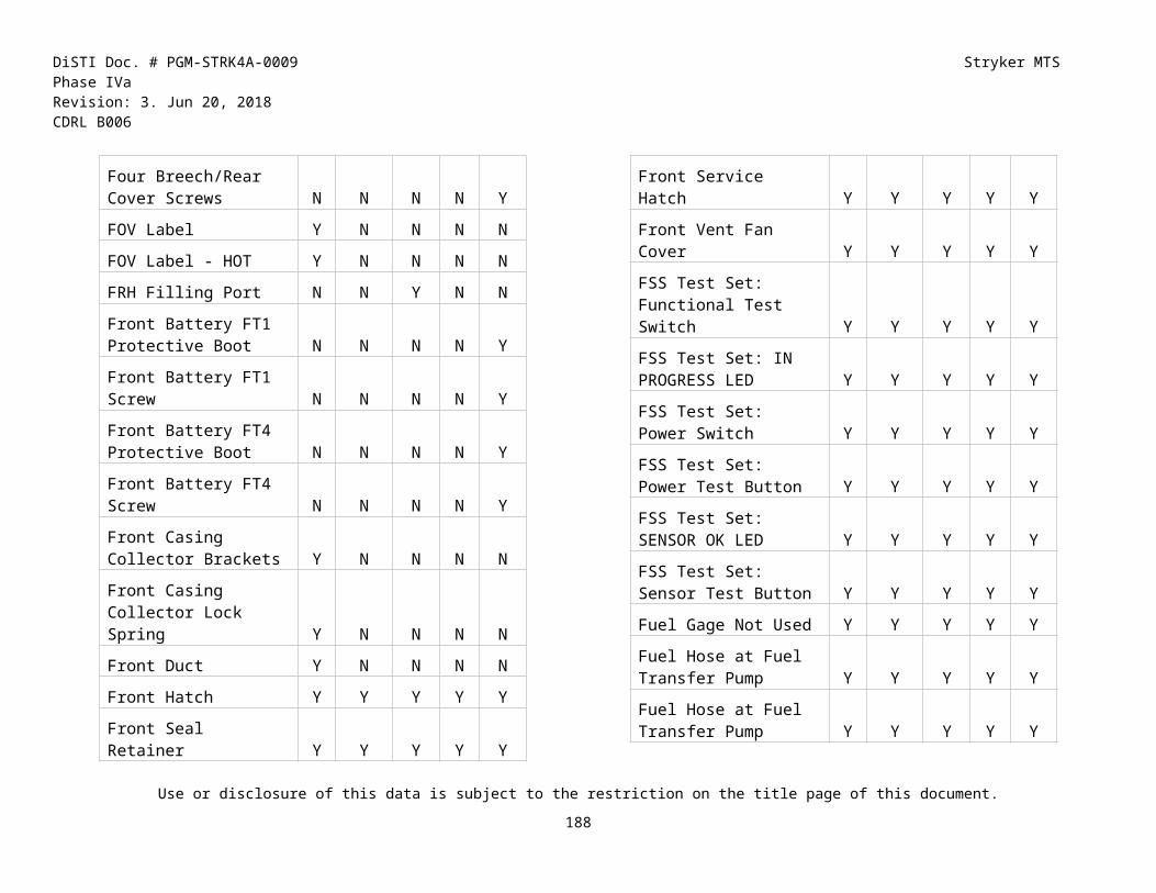
DiSTI Doc. # PGM-STRK4A-0009 Stryker MTS Phase IVaRevision: 3. Jun 20, 2018 CDRL B006
Button Task IETM Step Reference Usual Result ICV RWS ATGM FSV MCV MGSMotor Temperature LED Illuminated Troubleshooting Procedure Performed
Perform Motor Temperature LED Illuminated Troubleshooting Procedure
Motor Temperature LED Illuminated Troubleshooting Procedure Performed
N N Y N N N
No WARNING or CAUTION Messages Displayed on Central Control Panel
No WARNING or CAUTION Messages Displayed on Central Control Panel
The "No WARNING or CAUTION Messages Displayed on Central Control Panel" equipment condition has been completed.
N N N N N Y
Notify Contractor Logistics Support (CLS) to load software on HMU
Notify Contractor Logistics Support (CLS) to load software on HMU
Contractor Logistics Support (CLS) was notified to load software on HMU
Y N N N N N
Operate Ammunition Handling System Performed
Operate Ammunition Handling System Performed
The "Operate Ammunition Handling System Performed" equipment condition has been completed.
N N N N N Y
Operate Height Management System
Operate Height Management System - Auto and Aux power turned on- Engine started- Height Management System operated- Engine shutdown- Auto and Aux power turned off
N N N N N Y
Perform eject main gun ammunition
Perform eject main gun ammunition Main gun ammunition ejected N N N N N Y
Perform elevation motor potentiometer adjustment
Elevation motor potentiometer adjustment
- Ensured commander's station and turret powered up.- Elevation motor potentiometer adjustment performed.- No TP faults appeared on CCP.- Commander's station and turret powered down.
N N N N N Y
Use or disclosure of this data is subject to the restriction on the title page of this document.
189

DiSTI Doc. # PGM-STRK4A-0009 Stryker MTS Phase IVaRevision: 3. Jun 20, 2018 CDRL B006
Button Task IETM Step Reference Usual Result ICV RWS ATGM FSV MCV MGSPerform Engine Shutdown Perform engine shutdown - Engine shutdown Y Y Y N N YPerform Engine Start-Up Perform engine start-up - Engine started Y Y Y N N YPerform exhaust system inspection
Perform exhaust system inspection. Exhaust system inspection performed.
Y N N N N N
Perform Grips Test Perform Grips Test Grips Test Performed and passed
N N Y N N N
Perform HMU Built-In Test Perform HMU Built-In Test Height Management Unit (HMU) Built-In Test Performed. AUX power set to on.
Y N N N N N
Perform Road Test Attempted a road test. Road test was successful. Y N N N N NPerform Road Test For Fault 1594
Attempted a road test. Road test was successful N N N N N Y
Perform traverse drive gearbox adjustment
Perform traverse drive gearbox adjustment
Traverse drive gearbox adjustment performed.-The Traverse Drive D.C Motor was installed and connected.-The Traverse Drive Clutch was installed and connected.
N N N N N Y
Perform turret drive diagnostics traverse test
Perform turret drive diagnostics traverse test
Turret drive diagnostics traverse test performed.
N N N N N Y
Power Down Commander's Station and Turret
Power Down Commander's Station and Turret
Commander's Station and Turret Powered Down
N N N N N Y
Power Down Commander's Station and Turret and Stow CPV
Power Down Commander's Station and Turret and Stow CPV
Commander's Station and Turret Powered Down, CPV Stowed
N N N N N Y
Power Down Elevated Tow System (ETS)
Power Down Elevated Tow System (ETS)
Elevated Tow System (ETS) powered down
N N Y N N N
Power Down Remote Weapon Station
Power Down Remote Weapon Station Remote Weapon Station Powered Down
Y Y N N N N
Use or disclosure of this data is subject to the restriction on the title page of this document.
190

DiSTI Doc. # PGM-STRK4A-0009 Stryker MTS Phase IVaRevision: 3. Jun 20, 2018 CDRL B006
Button Task IETM Step Reference Usual Result ICV RWS ATGM FSV MCV MGSPower Pack Installation Steps 7 through 14 Maintenance ELO 1016
7. With assistance of second person, lift power pack off of power pack stand and position over engine compartment.8. With assistance of second person, lower power pack until just above hull mounts.9. Loosely install left and right front mounting bolts,
- Power Pack replaced- Power pack lowered into engine compartment- Mounting bolts loosely installed- Power Pack stand removed
Y N N N N N
Power Pack Removal Step 44. With assistance of second and third person, carefully lift power pack, then lower and secure to power pack stand. Maintenance ELO 1016
Removal Step 44. With assistance of second and third person, carefully lift power pack, then lower and secure to power pack stand.
Power pack lifted using suitable lifting device and lowered and secured to power pack stand.
Y N N N N N
Power Up Commander's Station and Turret
Power Up Commander's Station and Turret
Commander's Station and Turret Powered Up
N N N N N Y
Power Up Commander's Station and Turret - Operate Using GCH and CCH
Power Up Commander's Station and Turret
Commander's Station and Turret Powered Up
N N N N N Y
Power Up Elevated Tow System (ETS)
Power Up Elevated Tow System (ETS) Elevated Tow System (ETS) powered up
N N Y N N N
Power Up Remote Weapon Station
Power Up Remote Weapon Station Remote Weapon Station Powered Up
Y Y N N N N
Prime Backup Steering Pump
With transfer case supported on suitable surface, prime backup steering pump.
Backup steering pump primed. Y N N N N N
Pump hydraulic fluid into accumulator
Pump hydraulic fluid into accumulator Hydraulic fluid pumped into accumulator
N N N N N Y
Purge Air From Heater System
Purge air from heater system. Air purged from heater system. Y N N N N N
Use or disclosure of this data is subject to the restriction on the title page of this document.
191

DiSTI Doc. # PGM-STRK4A-0009 Stryker MTS Phase IVaRevision: 3. Jun 20, 2018 CDRL B006
Button Task IETM Step Reference Usual Result ICV RWS ATGM FSV MCV MGSRaise Vehicle Off Ground Raise Vehicle Off Ground Using Jacks, Vehicle Raised
Off GroundVehicle Secured With Jack StandsNose Armor RemovedIf the vehicle is being raised off the ground for the purpose of removing a wheel assembly, assume the nuts on the wheel drive have already been loosened.
Y N N N N N
Recover R-134 refrigerant oil and R-134 refrigerant from A/C 2 system
Using recovery function on charging station, recover R-134 refrigerant oil and R-134 refrigerant from A/C 2 system.
R-134 refrigerant oil and R-134 refrigerant recovered from A/C 2 system
Y N N N N N
Refuel Vehicle Refuel Vehicle Vehicle Refueled Y N N N N NRemove Accessory Panel Remove Accessory Panel. Accessory Panel removed. Y N N N N NRemove Air Inlet Diffuser - Remove air inlet diffuser. - Air inlet diffuser removed and
placed on workbench.Y N N N N N
Remove Alternator with assistance of second person and suitable lifting device
With assistance of second person and using suitable lifting device, remove alternator.
- Alternator removed- Nut, spring washer, and alternator pulley removed from alternator shaft.- Woodruff key removed from alternator shaft.
Y N N N N N
Remove Annunciator Module
Remove Annunciator Module Annunciator Module Removed Y N N N N N
Remove Automatic Fire Extinguishing System (AFES) Control Electronics Panel (CEP)
Remove Automatic Fire Extinguishing System (AFES) Control Electronics Panel (CEP)
Automatic Fire Extinguishing System (AFES) Control Electronics Panel (CEP) removed
Y N N N N N
Remove Climate Control Unit (CCU)
Remove Climate Control Unit (CCU) Climate Control Unit (CCU) removed
Y N N N N N
Remove Cooling Grille Assembly
Remove Cooling Grille Assembly. Cooling Grille Assembly removed.
Y Y Y Y Y Y
Use or disclosure of this data is subject to the restriction on the title page of this document.
192

DiSTI Doc. # PGM-STRK4A-0009 Stryker MTS Phase IVaRevision: 3. Jun 20, 2018 CDRL B006
Button Task IETM Step Reference Usual Result ICV RWS ATGM FSV MCV MGSRemove Cooling Grille Assembly using lifting device and with assistance of second person
Using lifting device and with assistance of second person, carefully lift cooling grille assembly clear of hull and set away from vehicle.
Cooling Grille Assembly lifted clear of hull and set away from vehicle.
Y Y Y Y Y Y
Remove Exhaust Fan Remove Exhaust Fan Exhaust Fan Removed N N Y N N NRemove Fire Control Unit (FCU)
Remove Fire Control Unit (FCU). Fire Control Unit (FCU) removed.
N Y N N N N
Remove First Differential Assembly from Transmission Lift using sling and lifting device
With assistance of second person and using sling and lifting device, remove first differential assembly from transmission lift.
First differential assembly removed from transmission lift with assistance of second person and use of sling and lifting device.
Y N N N N N
Remove Gauge Cluster Unit (GCU)
Remove Gauge Cluster Unit (GCU) Gauge Cluster Unit (GCU) removed
Y N N N N N
Remove Jack Stands Four 7 ton jack stands removed from under hull.
Y N N N N N
Remove Main Frame Assembly (MFA) using suitable lifting device
Place MFA on a stable work surface, using suitable lifting device.
MFA placed on a stable work surface.
N Y N N N N
Remove Mast Inspection Hatch
Remove Mast Inspection Hatch Mast Inspection Hatch Removed
N N Y N N N
Remove Power Distribution Panel (PDP) for Access
Move Power Distribution Panel (PDP) -Remove Power Distribution Panel (PDP) for access
- Battery Ground Disconnected- Power Distribution Panel (PDP) moved for access.
Y N N N N N
Remove Power Distribution Panel 2 (PDP 2) for Access
Power Distribution Panel 2 (PDP 2) for access
Power Distribution Panel 2 (PDP 2) removed for access
Y N N N N N
Remove Power Pack Assembly
Remove Power Pack Assembly Power Pack Assembly Removed
Y N N N N N
Use or disclosure of this data is subject to the restriction on the title page of this document.
193

DiSTI Doc. # PGM-STRK4A-0009 Stryker MTS Phase IVaRevision: 3. Jun 20, 2018 CDRL B006
Button Task IETM Step Reference Usual Result ICV RWS ATGM FSV MCV MGSRemove Sight Servo Assembly with assistance of second person and suitable lifting device
With assistance of second person, remove sight servo assembly with left side support assembly from right side support assembly. Place on a stable work surface and support with a block of wood.
Sight servo assembly with left side support assembly removed from right side support assembly and placed on a stable work surface and supported with a block of wood.
N Y N N N N
Remove TOW Missile Rack
Remove TOW Missile Rack TOW Missile Rack Removed N N Y N N N
Remove Transfer Case Assembly using lifting device and with assistance of second person
With assistance of second person, remove transfer case from hull support.
- Transfer case removed.- Pins and support assembly removed.- Backup steering pump fitting, packing and coupling removed.- Drain pan positioned to catch hudraulic fluid.- Fittings and O-rings removed.- Cotter pin, packing and O-rings discarded.
Y N N N N N
Remove Turret Power Distribution Panel (TPDP)
Remove Turret Power Distribution Panel (TPDP)
Turret Power Distribution Panel (TPDP) removed
N N N N N Y
Remove Wheel Chocks Remove Wheel Chocks Wheel chocks were removed. Y Y Y Y Y YRemove Wiring Harness SW2378
Remove Wiring Harness SW2378. Wiring Harness SW2378 Removed.
N N N N N Y
Replace Accessory Manifold
Replace Accessory Manifold. Accessory Manifold Replaced. Y N N N N N
Replace Accessory Manifold Pressure Protection Valve
Replace Accessory Manifold Pressure Protection Valve.
Accessory Manifold Pressure Protection Valve Replaced.
Y N N N N N
Use or disclosure of this data is subject to the restriction on the title page of this document.
194

DiSTI Doc. # PGM-STRK4A-0009 Stryker MTS Phase IVaRevision: 3. Jun 20, 2018 CDRL B006
Button Task IETM Step Reference Usual Result ICV RWS ATGM FSV MCV MGSReplace Accessory Manifold Solenoid Switch
Replace accessory manifold solenoid switch
- Accessory manifold pressure protection valve replaced.- Engine started and pneumatic system is pressurized.
Y N N N N N
Replace Accessory Panel Replace Accessory Panel. Accessory Panel Replaced. Y N N N N NReplace AFES CEP Replace AFES CEP. AFES CEP replaced. Y N N N N NReplace Annunciator Module
Replace annunciator module. Annunciator module replaced. Y N N N N N
Replace Auto 1 Battery Replace Auto 1 Battery. Auto 1 Battery Replaced. Y N N N N NReplace Auto 2 Battery Replace Auto 2 Battery. Auto 2 Battery Replaced. Y N N N N NReplace Autoloader Controller (ALC)
Replace Autoloader Controller (ALC) Autoloader Controller (ALC) Replaced.
N N N N N Y
Replace Autoloader Solenoid (Main Modular Manifold)
Replace Autoloader Solenoid (Main Modular Manifold)
Autoloader Solenoid (Main Modular Manifold) Replaced.
N N N N N Y
Replace Autoloader Solenoid Relay Box
Replace Autoloader Solenoid Relay Box Autoloader Solenoid Relay Box Replaced.
N N N N N Y
Replace Battery Power Supply (BPS)
Replace Battery Power Supply (BPS) Battery Power Supply (BPS) Replaced
N N Y N N N
Replace Brake Pedal Valve Assembly
Replace brake pedal valve assembly Brake pedal valve assembly replaced
Y N N N N N
Replace Card Rack Assembly (CRA)
Replace Card Rack Assembly (CRA) Card Rack Assembly (CRA) Replaced
N N Y N N N
Replace Carousel Left Canister Empty Proximity Switch Sensor and Bracket Replacement (Left Canister Sensor)
Replace Carousel Left Canister Empty Proximity Switch Sensor and Bracket Replacement (Left Canister Sensor)
Carousel Left Canister Empty Proximity Switch Sensor and Bracket Replacement (Left Canister Sensor) Replaced.
N N N N N Y
Replace Central Control Panel (CCP)
Replace Central Control Panel (CCP) Central Control Panel (CCP) replaced
N N N N N Y
Replace Climate Control Unit
Replace Climate Control Unit Climate Control Unit Replaced Y N N N N N
Use or disclosure of this data is subject to the restriction on the title page of this document.
195

DiSTI Doc. # PGM-STRK4A-0009 Stryker MTS Phase IVaRevision: 3. Jun 20, 2018 CDRL B006
Button Task IETM Step Reference Usual Result ICV RWS ATGM FSV MCV MGSReplace CMS SIRE and Interface Plate
Replace CMS SIRE and Interface Plate CMS SIRE and Interface Plate Replaced.
N N N N N Y
Replace Cocking Actuator Replace Cocking Actuator Cocking Actuator Replaced N Y N N N NReplace Collimator Battery Replace Collimator Battery Collimator Battery Replaced. N N N N N YReplace Commanders Control Handle (CCH)
Replace Commanders Control Handle Commanders Control Handle (CCH) Replaced.
N N N N N Y
Replace Commanders Pan Viewer Electronic Unit (CPVEU) and Brackets
Replace Commanders Pan Viewer Electronic Unit (CPVEU) and Brackets
Commanders Pan Viewer Electronic Unit (CPVEU) and Brackets Replaced.
N N N N N Y
Replace Commander's Panel Assembly (CPA)
Replace Commander's Panel Assembly (CPA)
Commander's Panel Assembly (CPA) Replaced
N N Y N N N
Replace Compact Modular Sight (CMS) Sight Body and Modular Control Panel (MCP)
Replace Compact Modular Sight (CMS) Sight Body and Modular Control Panel (MCP)
Compact Modular Sight (CMS) Sight Body and Modular Control Panel (MCP) replaced
N N N N N Y
Replace Diagnostic Control Unit
Replace Diagnostic Control Unit. Diagnostic Control Unit Replaced.
Y N N N N N
Replace Digital Control Assembly (DCA)
Replace Digital Control Assembly (DCA) - Digital Control Assembly (DCA) Replaced.- Main gun centered over front deck and near 0 degrees elevation.
N N N N N Y
Replace Driver's Instrument Panel
Replace Driver's Instrument Panel. Driver's Instrument Panel Replaced.
Y N N N N N
Replace Driver's Instrument Panel without AFES safeguards engaged or disengaged
Replace Driver's Instrument Panel. Driver's Instrument Panel Replaced.
Y N N N N N
Replace Elevation Drive Flex Shaft
Replace Elevation Drive Flex Shaft Elevation Drive Flex Shaft replaced.
N N N N N Y
Replace Engine Replace engine. Engine replaced. Y N N N N NReplace Engine Fan Assembly
Replace Engine Fan Assembly. Engine Fan Assembly Replaced.
Y N N N N N
Use or disclosure of this data is subject to the restriction on the title page of this document.
196

DiSTI Doc. # PGM-STRK4A-0009 Stryker MTS Phase IVaRevision: 3. Jun 20, 2018 CDRL B006
Button Task IETM Step Reference Usual Result ICV RWS ATGM FSV MCV MGSReplace Engine Fan Hydraulic Hoses
Replace Engine Compartment Fan Hydraulic Hoses and Components, as applicable.
Engine Compartment Hydraulic Hoses Replaced.
Y N N N N N
Replace Fire Control System (FCS)
Replace Fire Control System (FCS) Fire Control System (FCS) Replaced
N N Y N N N
Replace Fire Control Unit (FCU)
Replace Fire Control Unit (FCU) Fire Control Unit Replaced N Y N N N N
Replace Fuel/Water Separator Filter Element
Replace fuel/water separator filter element
Fuel/water separator filter element replaced
Y N N N N N
Replace Gauge Cluster Unit
Replace Gauge Cluster Unit. Gauge Cluster Unit Replaced. Y N N N N N
Replace Gunner's Panel Assembly (GPA)
Replace Gunner's Panel Assembly (GPA)
Gunner's Panel Assembly (GPA) Replaced
N N Y N N N
Replace Hatch Interrupt Unit (HIU)
Replace Hatch Interrupt Unit Hatch Interrupt Unit replaced. N N N N N Y
Replace Height Control Manifold
Replace Height Control Manifold Height Control Manifold Replaced
Y N N N N N
Replace Height Management Unit
Replace Height Management Unit Height Management Unit Replaced.
Y N N N N N
Replace Hull/Turret Position Sensor (HTPS)
Replace Hull/Turret Position Sensor (HTPS)
Hull/Turret Position Sensor (HTPS) Replaced.
N N N N N Y
Replace Hydropneumatic Strut Charge Fittings
Replace Third and Fourth Axle Hydropneumatic Strut Charge Fitting and Seal
Third and Fourth Axle Hydropneumatic Strut Charge Fitting and Seal Replace
Y N N N N N
Replace Idler Pulley Assembly (Water Pump)
Replace Idler Pulley Assembly. Water Pump Idler Pulley Assembly Replaced.
Y N N N N N
Replace Left #4 Brake Actuator and Wedge Assembly
Replace Left #4 Brake Actuator and Wedge Assembly.
Left #4 Brake Actuator and Wedge Assembly Replaced.
Y N N N N N
Replace Left Rear Hydropneumatic Strut
Replace Rear Hydropneumatic Strut Rear Hydropneumatic Strut Replaced
Y N N N N N
Replace Loader's Panel Assembly (LPA)
Replace Loader's Panel Assembly (LPA) Loader's Panel Assembly (LPA) Replaced
N N Y N N N
Use or disclosure of this data is subject to the restriction on the title page of this document.
197

DiSTI Doc. # PGM-STRK4A-0009 Stryker MTS Phase IVaRevision: 3. Jun 20, 2018 CDRL B006
Button Task IETM Step Reference Usual Result ICV RWS ATGM FSV MCV MGSReplace Low Ammo Sensor
Replace Low Ammo Sensor Low Ammo Sensor Replaced N Y N N N N
Replace Manual Firing Mechanism
Replace Manual Firing Mechanism Manual Firing Mechanism Replaced.
N N N N N Y
Replace Manual Handstation
Replace Manual Handstation Manual Handstation Replaced. N N N N N Y
Replace Mobile Gun Computer (MGC) Assembly, T-Bracket, and Shock Mount Bracket.
Replace Mobile Gun Computer (MGC) Assembly, T-Bracket, and Shock Mount Bracket.
Mobile Gun Computer (MGC) Assembly, T-Bracket, and Shock Mount Bracket Replaced.
N N N N N Y
Replace Power Distribution Assembly (PDA)
Replace Power Distribution Assembly (PDA)
Power Distribution Assembly (PDA) Replaced
N N Y N N N
Replace Power Distribution Panel (ICV)
Replace Power Distribution Panel. Power Distribution Panel replaced.
Y N N N N N
Replace Power Pack Interface Unit
Replace Power Pack Interface Unit. Power Pack Interface Unit Replaced.
Y N N N N N
Replace Pressure Compensated Solenoid
Replace Pressure Compensated Solenoid
Pressure Compensated Solenoid Replaced.
N N N N N Y
Replace Ramp Control Box
Replace Ramp Control Box. Ramp Control Box Replaced. Y N N N N N
Replace Rear Vent Fan Replace troop rear vent fan. Rear vent fan replaced. Y N N N N NReplace Recuperator Assembly
Replace recuperator assembly. Rcuperator assembly replaced.
N N N N Y N
Replace Remote Combat Lock, Front Cable Assembly
Replace Remote Combat Lock, Front Cable Assembly
Remote Combat Lock, Front Cable Assembly Replaced.
N N N N N Y
Replace Replenisher Controller
Replace Replenisher Controller Replenisher Controller Replaced.
N N N N N Y
Replace Resolver Resolver Replacement Resolver Replaced N N Y N N NReplace Shift Cylinder Assembly
Replace Shift Cylinder Assembly. Shift Cylinder Assembly Replaced.
Y N N N N N
Replace Shifter Replace Shifter. Shifter Replaced Y N N N N NReplace Sight Servo Assembly
Replace Sight Servo Assembly Sight Servo Assembly Replaced
N Y N N N N
Use or disclosure of this data is subject to the restriction on the title page of this document.
198

DiSTI Doc. # PGM-STRK4A-0009 Stryker MTS Phase IVaRevision: 3. Jun 20, 2018 CDRL B006
Button Task IETM Step Reference Usual Result ICV RWS ATGM FSV MCV MGSReplace Starter Motor Replace Starter Motor Starter Motor Replaced Y N N N N NReplace Target Acquisition System (TAS)
Replace Target Acquisition System (TAS)
Target Acquisition System (TAS) Replaced
N N Y N N N
Replace Tee Fitting / Shift Cylinder Upper Supply Hoses
Replace Tee Fitting / Shift Cylinder Upper Supply Hoses.
Tee Fitting / Shift Cylinder Upper Supply Hoses Replaced.
Y N N N N N
Replace Thermal Imaging Module
Replace Thermal Imaging Module Thermal Imaging Module Replaced
N Y N N N N
Replace Transmission ECU
Replace Transmission ECU. Transmission ECU Replaced. Y N N N N N
Replace Traverse Drive Motor (with TDS)
Replace Traverse Drive Motor (with TDS)
Traverse Drive Motor (with TDS) Replaced.
N N N N N Y
Replace Turret Auxiliary Switch Panel (TASP)
Replace Turret Auxiliary Switch Panel (TASP)
Turret Auxiliary Switch Panel (TASP) replaced.
N N N N N Y
Replace Turret Power Distribution Panel (TPDP) and Bracket
Replace Turret Power Distribution Panel (TPDP) and Bracket
Turret Power Distribution Panel (TPDP) and Bracket Replaced.
N N N N N Y
Replace Turret System Electronic Unit (TSEU) Assembly, Brackets and Resilient Mounts
Replace Turret System Electronic Unit (TSEU) Assembly, Brackets and Resilient Mounts
Turret System Electronic Unit (TSEU) Assembly, Brackets and Resilient Mounts Replaced.
N N N N N Y
Replace Upper Right Light Receiver
Replace Upper Right Light Receiver Upper Right Light Receiver Replaced.
N N N N N Y
Replace Video Display Terminal
Replace Video Display Terminal Video Display Terminal Replaced
Y N N N N N
Replace Visual Imaging Module
Replace Visual Imaging Module Visual Imaging Module Replaced
N Y N N N N
Replace Voltage Regulator Replace Voltage Regulator Voltage Regulator Replaced Y N N N N NReplace Wiring Harness 1W106B-7
Replace Wiring Harness 1W106B-7 Wiring Harness 1W106B-7 replaced.
N N N N N Y
Replace Wiring Harness 1W107-7
Replace Wiring Harness 1W107-7 Wiring Harness 1W107-7 Replaced.
N N N N N Y
Replace Wiring Harness 1W109-7
Replace Wiring Harness 1W109-7 Wiring Harness 1W109-7 Replaced.
N N N N N Y
Use or disclosure of this data is subject to the restriction on the title page of this document.
199

DiSTI Doc. # PGM-STRK4A-0009 Stryker MTS Phase IVaRevision: 3. Jun 20, 2018 CDRL B006
Button Task IETM Step Reference Usual Result ICV RWS ATGM FSV MCV MGSReplace Wiring Harness 1W202-7
Replace Wiring Harness 1W202-7 Wiring Harness 1W202-7 Replaced.
N N N N N Y
Replace Wiring Harness 1W202A-7
Replace Wiring Harness 1W202A-7 Wiring Harness 1W202A-7 replaced.
N N N N N Y
Replace Wiring Harness 1W202C-7
Replace Wiring Harness 1W202C-7 Wiring Harness 1W202C-7 Replaced.
N N N N N Y
Replace Wiring Harness 1W206-7
Replace Wiring Harness 1W206-7 Wiring Harness 1W206-7 Replaced.
N N N N N Y
Replace Wiring Harness 1W215A-7
Replace Wiring Harness 1W215A-7 Wiring Harness 1W215A-7 replaced.
N N N N N Y
Replace Wiring Harness 1W401A-7
Replace Wiring Harness 1W401A-7 Wiring Harness 1W401A-7 Replaced.
N N N N N Y
Replace Wiring Harness W-1 (RWS)
Replace Wiring Harness W-1 Wiring Harness W-1 Replaced N Y N N N N
Replace Wiring Harness W16
Replace Wiring Harness W16 Wiring Harness W16 Replaced N Y N N N N
Replace Wiring Harness W215A-7
Replace Wiring Harness W215A-7 Wiring Harness W215A-7 Replaced.
N N N N N Y
Replace Wiring Harness W4
Replace Wiring Harness W4 Wiring Harness W4 Replaced Y N N N N N
Replace Wiring Harness W418A
Replace Wiring Harness W418A Wiring Harness W418A Replaced
Y N N N N N
Replace Wiring Harness W451
Replace Wiring Harness W451 Wiring Harness W451 Replaced
Y N N N N N
Replace Wiring Harness W459
Replace Wiring Harness W459. Wiring Harness W459 replaced.
Y N N N N N
Replenish ammunition using CCP
Perform replenish ammunition operation using CCP
Ammunition replenished using CCP.
N N N N N Y
Replenish autoloader carousel using gauge tool M393 (HEP)
Replenish autoloader carousel using gauge tool M393 (HEP)
Autoloader carousel replenished using gauge tool M393 (HEP)
N N N N N Y
Replenish autoloader carousel using gauge tool M456 (HEAT)
Replenish autoloader carousel using gauge tool M456 (HEAT)
Autoloader carousel replenished using gauge tool M456 (HEAT)
N N N N N Y
Use or disclosure of this data is subject to the restriction on the title page of this document.
200

DiSTI Doc. # PGM-STRK4A-0009 Stryker MTS Phase IVaRevision: 3. Jun 20, 2018 CDRL B006
Button Task IETM Step Reference Usual Result ICV RWS ATGM FSV MCV MGSReplenisher Calibration Perform replenisher calibration Replenisher Calibration
performed.N N N N N Y
Restow autoloader manually
Restow autoloader manually Autoloader manually restowed. N N N N N Y
Restow main gun ammunition using Commander's Control Handle (CCH)
Restow main gun ammunition using Commander's Control Handle (CCH)
Restow operation was successful.
N N N N N Y
Rotate RWS to 0° Azimuth Rotate RWS to 0° azimuth. RWS has been rotated to 0° azimuth.
N Y N N N N
Rotate RWS to 0° Azimuth and 0° Elevation
Rotate RWS to 0° azimuth and 0° elevation.
RWS has been rotated to 0° azimuth and 0° elevation.
N Y N N N N
Rotate RWS to 0° Azimuth and -20° Elevation
Rotate RWS to 0° azimuth and -20° elevation.
RWS has been rotated to 0° azimuth and -20° elevation.
N Y N N N N
Rotate RWS to 0° Azimuth and 60° Elevation
Rotate RWS to 0° Azimuth and 60° Elevation.
RWS has been rotated to 0° Azimuth and 60° Elevation.
N Y N N N N
Rotate RWS to -20° Elevation
Rotate RWS to -20° elevation. RWS has been rotated to -20° elevation.
N Y N N N N
Service Breechblock Service Breechblock Breechblock serviced. Main Gun Travel Lock has been disengaged.
N N N N N Y
Single Step Maintenance: ALC Home
Single Step Maintenance: ALC Home Single Step Maintenance: ALC Home performed.
N N N N N Y
Single Step Maintenance: Dry Load
Single Step Maintenance: Dry Load Single Step Maintenance: Dry Load performed.
N N N N N Y
Single Step Maintenance: Normal Load
Single Step Maintenance: Normal Load Single Step Maintenance: Normal Load performed.
N N N N N Y
Single Step Maintenance: Normal Restow
Single Step Maintenance: Normal Restow
Single Step Maintenance: Normal Restow performed.Engine is running and Commander Station is powered up.
N N N N N Y
Steering System Alignment Steering System Alignment Steering system alignment performed.
Y N N N N N
Use or disclosure of this data is subject to the restriction on the title page of this document.
201

DiSTI Doc. # PGM-STRK4A-0009 Stryker MTS Phase IVaRevision: 3. Jun 20, 2018 CDRL B006
Button Task IETM Step Reference Usual Result ICV RWS ATGM FSV MCV MGSTest Coolant Additive Test Coolant Additive. Coolant additive is within
specifications for operating conditions.
Y N N N N N
Traverse turret using GCH until gunner's turret basket screens are aligned with left side of replenisher
Traverse turret using GCH until gunner's turret basket screens are aligned with left side of replenisher
Turret traversed using GCH until gunner's turret basket screens are aligned with left side of replenisher
N N N N N Y
Turret - Slowly raise turret from stand, position on hull then lower turret into hull. Installs new turret
- With two people guiding turret, third person slowly raise turret. Lift turret from stand and position on hull.- Align turret to hull reference marks established during removal.- Lower turret into hull.
- Turret Replaced- Turret slowly raised from stand, positioned on hull and lowered into hull.
N N N N N Y
Turret - Slowly raise turret from stand, position on hull then lower turret into hull. Installs original turret
- With two people guiding turret, third person slowly raise turret. Lift turret from stand and position on hull.- Align turret to hull reference marks established during removal.- Lower turret into hull.
Turret slowly raised from stand, positioned on hull and lowered into hull.
N N N N N Y
Turret - Slowly raise turret, remove turret from hull and then position on turret stand.
- With two people guiding turret removal, third person slowly raise turret.- Remove turret from hull and position on turret stand.
Turret slowly raised from vehicle, removed from hull and positioned on turret stand.
N N N N N Y
Turret Drive System Does Not Operate Properly Troubleshooting Completed
Turret Drive System Does Not Operate Properly Troubleshooting Completed
The "Turret Drive System Does Not Operate Properly Troubleshooting" equipment condition has been completed.
N N N N N Y
Turret Drive System Does Not Operate Properly Troubleshooting Completed For ELOs 1604 and 1605
Turret Drive System Does Not Operate Properly Troubleshooting Completed
- Turret Drive System Does Not Operate Properly Troubleshooting Completed- Elevation Drive Brake Clutch replaced
N N N N N Y
Use or disclosure of this data is subject to the restriction on the title page of this document.
202

DiSTI Doc. # PGM-STRK4A-0009 Stryker MTS Phase IVaRevision: 3. Jun 20, 2018 CDRL B006
Button Task IETM Step Reference Usual Result ICV RWS ATGM FSV MCV MGSTurret Removed Condition - Turret Removed - Disconnected battery
grounds.- Turret removed and placed on Turret Stand.
N N N N N Y
Unload M6 Smoke Grenade Discharger (ATGM)
Unload M6 Smoke Grenade Discharger M6 Smoke Grenade Dischargers have been unloaded.
N N Y N N N
Unload M6 Smoke Grenade Launcher (RWS)
Unload M6 Smoke Grenade Launcher Grenades are unloaded Y Y N N N N
Unload TOW Launcher Unload TOW Launcher TOW Launcher has been unloaded.
N N Y N N N
USEU CAUTION Message Not Displayed on Central Control Panel
USEU CAUTION Message Not Displayed on Central Control Panel
The "USEU CAUTION Message Not Displayed on Central Control Panel" equipment condition has been completed.
N N N N N Y
Wiring Harness 1W105-7 Inspection
Wiring Harness 1W105-7 Inspection Wiring Harness Inspected for Damage and Passed.
N N N N N Y
Wiring Harness 1W105C-7 Inspection
Wiring Harness 1W105C-7 Inspection Wiring Harness Inspected for Damage and Passed.
N N N N N Y
Wiring Harness 1W105D-7 Inspection
Wiring Harness 1W105D-7 Inspection Wiring Harness Inspected for Damage and Passed.
N N N N N Y
Wiring Harness 1W106-7 Inspection
Wiring Harness 1W106-7 Inspection Wiring Harness Inspected for Damage and Passed.
N N N N N Y
Wiring Harness 1W106B-7 Inspection
Wiring Harness 1W106B-7 Inspection Wiring Harness Inspected for Damage and Passed.
N N N N N Y
Wiring Harness 1W107-7 Inspection
Wiring Harness 1W107-7 Inspection Wiring Harness Inspected for Damage and Passed.
N N N N N Y
Wiring Harness 1W109-7 Inspection
Wiring Harness 1W109-7 Inspection Wiring Harness Inspected for Damage and Passed.
N N N N N Y
Wiring Harness 1W202-7 Inspection
Wiring Harness 1W202-7 Inspection Wiring Harness Inspected for Damage and Passed.
N N N N N Y
Wiring Harness 1W202A-7 Inspection
Wiring Harness 1W202A-7 Inspection Wiring Harness Inspected for Damage and Passed.
N N N N N Y
Use or disclosure of this data is subject to the restriction on the title page of this document.
203

DiSTI Doc. # PGM-STRK4A-0009 Stryker MTS Phase IVaRevision: 3. Jun 20, 2018 CDRL B006
Button Task IETM Step Reference Usual Result ICV RWS ATGM FSV MCV MGSWiring Harness 1W202B-7 Inspection
Wiring Harness 1W202B-7 Inspection Wiring Harness Inspected for Damage and Passed.
N N N N N Y
Wiring Harness 1W202C-7 Inspection
Wiring Harness 1W202C-7 Inspection Wiring Harness Inspected for Damage and Passed.
N N N N N Y
Wiring Harness 1W202J-7 Inspection
Wiring Harness 1W202J-7 Inspection Wiring Harness Inspected for Damage and Passed.
N N N N N Y
Wiring Harness 1W206-7 Inspection
Wiring Harness 1W206-7 Inspection Wiring Harness Inspected for Damage and Passed.
N N N N N Y
Wiring Harness 1W215A-7 Inspection
Wiring Harness 1W215A-7 Inspection Wiring Harness Inspected for Damage and Passed.
N N N N N Y
Wiring Harness 1W215B-7 Inspection
Wiring Harness 1W215B-7 Inspection Wiring Harness Inspected for Damage and Passed.
N N N N N Y
Wiring Harness 1W215C-7 Inspection
Wiring Harness 1W215C-7 Inspection Wiring Harness Inspected for Damage and Passed.
N N N N N Y
Wiring Harness 1W216-7 Inspection
Wiring Harness 1W216-7 Inspection Wiring Harness Inspected for Damage and Passed.
N N N N N Y
Wiring Harness 1W217-7 Inspection
Wiring Harness 1W217-7 Inspection Wiring Harness Inspected for Damage and Passed.
N N N N N Y
Wiring Harness 1W2S408-7 Inspection
Wiring Harness 1W2S408-7 Inspection Wiring Harness Inspected for Damage and Passed.
N N N N N Y
Wiring Harness 1W302-7 Inspection
Wiring Harness 1W302-7 Inspection Wiring Harness Inspected for Damage and Passed.
N N N N N Y
Wiring Harness 1W304-7 Inspection
Wiring Harness 1W304-7 Inspection Wiring Harness Inspected for Damage and Passed.
N N N N N Y
Wiring Harness 1W3-7 Inspection
Wiring Harness 1W3-7 Inspection Wiring Harness Inspected for Damage and Passed.
N N N N N Y
Wiring Harness 1W400-7 Inspection
Wiring Harness 1W400-7 Inspection Wiring Harness Inspected for Damage and Passed.
N N N N N Y
Wiring Harness 1W401A-7 Inspection
Wiring Harness 1W401A-7 Inspection Wiring Harness Inspected for Damage and Passed.
N N N N N Y
Wiring Harness 1W409-7 Inspection
Wiring Harness 1W409-7 Inspection Wiring Harness Inspected for Damage and Passed.
N N N N N Y
Wiring Harness 1W411-7 Inspection
Wiring Harness 1W411-7 Inspection Wiring Harness Inspected for Damage and Passed.
N N N N N Y
Use or disclosure of this data is subject to the restriction on the title page of this document.
204

DiSTI Doc. # PGM-STRK4A-0009 Stryker MTS Phase IVaRevision: 3. Jun 20, 2018 CDRL B006
Button Task IETM Step Reference Usual Result ICV RWS ATGM FSV MCV MGSWiring Harness 1W412-7 Inspection
Wiring Harness 1W412-7 Inspection Wiring Harness Inspected for Damage and Passed.
N N N N N Y
Wiring Harness 1W700-7 Inspection
Wiring Harness 1W700-7 Inspection Wiring Harness Inspected for Damage and Passed.
N N N N N Y
Wiring Harness SW2378 Inspection
Wiring Harness SW2378 Inspection Wiring Harness Inspected for Damage and Passed.
N N N N N Y
Wiring Harness W1 Inspection (RWS)
Wiring Harness W1 Inspection Wiring Harness W1 Inspected for Damage and Passed.
N Y N N N N
Wiring Harness W16 Inspection
Wiring Harness W16 Inspection Wiring Harness W16 Inspected for Damage and Passed.
N Y N N N N
Wiring Harness W19 Inspection
Wiring Harness W19 Inspection Wiring Harness W19 Inspected for Damage and Passed.
N Y N N N N
Wiring Harness W201 Inspection
Wiring Harness W201 Inspection Wiring Harness W201 Inspected for Damage and Passed.
N N Y N N N
Wiring Harness W203 Inspection
Wiring Harness W203 Inspection Wiring Harness W203 Inspected for Damage and Passed.
N N Y N N N
Wiring Harness W205 Inspection
Wiring Harness W205 Inspection Wiring Harness W205 Inspected for Damage and Passed.
N N Y N N N
Wiring Harness W205A-7 Inspection
Wiring Harness W205A-7 Inspection Wiring Harness Inspected for Damage and Passed.
N N N N N Y
Wiring Harness W213 Inspection
Wiring Harness W213 Inspection Wiring Harness W213 Inspected for Damage and Passed.
N N Y N N N
Wiring Harness W214 Inspection
Wiring Harness W214 Inspection Wiring Harness W214 Inspected for Damage and Passed.
N N Y N N N
Wiring Harness W214A-7 Inspection
Wiring Harness W214A-7 Inspection Wiring Harness Inspected for Damage and Passed.
N N N N N Y
Use or disclosure of this data is subject to the restriction on the title page of this document.
205

DiSTI Doc. # PGM-STRK4A-0009 Stryker MTS Phase IVaRevision: 3. Jun 20, 2018 CDRL B006
Button Task IETM Step Reference Usual Result ICV RWS ATGM FSV MCV MGSWiring Harness W215A-7 Inspection
Wiring Harness W215A-7 Inspection Wiring Harness Inspected for Damage and Passed.
N N N N N Y
Wiring Harness W217 Inspection
Wiring Harness W217 Inspection Wiring Harness W217 Inspected for Damage and Passed.
N N Y N N N
Wiring Harness W224 Inspection
Wiring Harness W224 Inspection Wiring Harness W224 Inspected for Damage and Passed.
N N Y N N N
Wiring Harness W225 Inspection
Wiring Harness W225 Inspection Wiring Harness W225 Inspected for Damage and Passed.
N N Y N N N
Wiring Harness W227 Inspection
Wiring Harness W227 Inspection Wiring Harness W227 Inspected for Damage and Passed.
N N Y N N N
Wiring Harness W3 Inspection
Wiring Harness W3 Inspection Wiring Harness W3 Inspected for Damage and Passed.
N Y N N N N
Wiring Harness W4 Inspection
Inspect connectors and exposed portions of wiring harness W4 for damage.
Wiring harness W4 inspected for damage and passed.
Y N N N N N
Wiring Harness W401-7 Inspection
Wiring Harness W401-7 Inspection Wiring Harness Inspected for Damage and Passed.
N N N N N Y
Wiring Harness W413 Inspection
Wiring Harness W413 Inspection Wiring Harness W413 inspected for damage and passed.
Y N N N N N
Wiring Harness W414 Inspection
Inspect connectors and exposed portions of wiring harness W414 for damage.
Wiring harness W414 inspected for damage and passed.
Y N N N N N
Wiring Harness W415 Inspection
Wiring Harness W415 Inspection Wiring Harness W415 Inspected for Damage and Passed.
Y N N N N N
Wiring Harness W418 Inspection
Inspect all connectors and exposed portions of wiring harness W418 for damage.
Wiring harness W418 inspected for damage and passed.
Y N N N N N
Use or disclosure of this data is subject to the restriction on the title page of this document.
206

DiSTI Doc. # PGM-STRK4A-0009 Stryker MTS Phase IVaRevision: 3. Jun 20, 2018 CDRL B006
Button Task IETM Step Reference Usual Result ICV RWS ATGM FSV MCV MGSWiring Harness W418A Inspection
Inspect all connectors and exposed portions of wiring harness W418A for damage.
Wiring harness W418A inspected for damage and passed.
Y N N N N N
Wiring Harness W421 Inspection
Inspect connectors and exposed portions of wiring harness W421 for damage.
Wiring harness W421 inspected for damage and passed.
Y N N N N N
Wiring Harness W422 Inspection
Inspect connectors and exposed portions of wiring harness W422 for damage.
Wiring harness W422 inspected for damage and passed.
Y N N N N N
Wiring Harness W423 Inspection
Inspect connectors and exposed portions of wiring harness W423 for damage.
Wiring harness W423 inspected for damage and passed.
Y N N N N N
Wiring Harness W425 Inspection
Inspect connectors and exposed portions of wiring harness W425 for damage.
Wiring harness W425 inspected for damage and passed.
Y N N N N N
Wiring Harness W429 Inspection
Inspect All Connectors and Exposed Portions of Wiring Harness W429 for Damage.
Wiring harness W429 Inspected for Damage and Passed.
Y N N N N N
Wiring Harness W434 Inspection
Inspect connectors and exposed portions of wiring harness W434 for damage.
Wiring Harness W434 Inspected for Damage and Passed.
Y N N N N N
Wiring Harness W451 Inspection
Inspect connectors and exposed portions of wiring harness W451 for damage.
Wiring harness W451 inspected for damage and passed.
Y N N N N N
Wiring Harness W452 Inspection
Wiring Harness W452 Inspection Wiring Harness W452 Inspected for Damage and Passed.
Y N N N N N
Wiring Harness W459 Inspection
Inspect connectors and exposed portions of wiring harness W459 for damage.
Wiring harness W459 inspected for damage and passed.
Y N N N N N
Wiring Harness W478 Inspection
Wiring Harness W478 Inspection Wiring Harness W478 Inspected for Damage and Passed.
N Y N N N N
Use or disclosure of this data is subject to the restriction on the title page of this document.
207

DiSTI Doc. # PGM-STRK4A-0009 Stryker MTS Phase IVaRevision: 3. Jun 20, 2018 CDRL B006
Button Task IETM Step Reference Usual Result ICV RWS ATGM FSV MCV MGSWiring Harness W5 Inspection
Wiring Harness W5 Inspection Wiring Harness W5 Inspected for Damage and Passed.
N Y N N N N
Wiring Harness W531D-7 Inspection
Wiring Harness W531D-7 Inspection Wiring Harness Inspected for Damage and Passed.
N N N N N Y
Use or disclosure of this data is subject to the restriction on the title page of this document.
208

DiSTI Doc. # PGM-STRK4A-0009 Stryker MTS Phase IVaRevision: 3. Jun 20, 2018 CDRL B006
APPENDIX F RWS TROUBLESHOOTINGProcedures supported in the Phase IVa DTT have data in the IETM Navigation and Troubleshooting Path column and correspond to the IAV TM dated 10 Dec 2015. Other procedures are included for reference only but have not been updated and are not supported in the Phase IVa DTT.
ID IETM Navigation System Symptom Fault Description Faulty Component
Troubleshooting Path
F001
Remote Weapon System
BATTLE OVERRIDE DOES NOT FUNCTION Battle override does not function
Replace FCU
F002
Troubleshooting Procedures --> Field - Troubleshooting Procedure --> REMOTE WEAPON SYSTEM TROUBLESHOOTING
Remote Weapon System
CONTROL GRIP CONTROL LOST OR SYSTEM STATUS MESSAGE: CONTROL GRIP - ERROR OR CG: CONTROL GRIP FAILURE OR CG: CONTROL GRIP COMMUNICATION FAILURE
Control Grip Control Lost
Replace Wiring Harness W-1
No, Perform Offset, Pass, Test 91, Pass, Test 91, Pass, Test 91, Pass, Perform Offset, Pass, Test 91, Pass, Test 91, Pass, Test 91, Pass, Perform Offset, Pass, Test 91, Pass, Replace Wiring Harness W-1, No
F003
Troubleshooting Procedures --> Field - Troubleshooting Procedure --> REMOTE WEAPON SYSTEM TROUBLESHOOTING
Remote Weapon System
FIRE CONTROL UNIT DOES NOT POWER UP – RWS OR FCU: MISSING 12V DC
Fire Control Unit does not power RWS
Replace FCU Yes, No, No, Test 89, Pass, Test 89, Pass, Test 89, Pass, Replace FCU, Yes
F004
Remote Weapon System
FIRE CONTROL UNIT MEMBRANE BUTTONS DO NOT RESPOND
Fire Control Unit Membrane Buttons do not Respond
Replace FCU
F005
Remote Weapon System
PRIMARY WEAPON NOT DETECTED Primary Weapon not Detected
Replace Sight Servo Assembly (SSA)
Use or disclosure of this data is subject to the restriction on the title page of this document.
209

DiSTI Doc. # PGM-STRK4A-0009 Stryker MTS Phase IVaRevision: 3. Jun 20, 2018 CDRL B006
ID IETM Navigation System Symptom Fault Description Faulty Component
Troubleshooting Path
F006
Remote Weapon System
REMOTE WEAPON STATION DOES NOT ROTATE IN AZIMUTH
Remote Weapon Station does not rotate in Azimuth
Replace MFA
F007
Remote Weapon System
REMOTE WEAPON STATION DOES NOT ROTATE IN AZIMUTH
Remote Weapon Station does not rotate in Azimuth
Replace CG
F008
Troubleshooting Procedures --> Field - Troubleshooting Procedure --> REMOTE WEAPON SYSTEM TROUBLESHOOTING
Remote Weapon System
REMOTE WEAPON STATION STATUS ERRORS ON POWER UP
Software System Error on Power up
Replace SSA Yes, No, Replace SSA, Yes
F009
Remote Weapon System
THERMAL IMAGING MODULE INFORMATION NOT PRESENT
Thermal imaging module information not present
Replace FCU
F010
Troubleshooting Procedures --> Field - Troubleshooting Procedure --> REMOTE WEAPON SYSTEM TROUBLESHOOTING
Remote Weapon System
THERMAL IMAGING MODULE INFORMATION NOT PRESENT OR TIM: FCU: VIDEO UNDERLAY CARD REPORTS CAMERA VIDEO MISSING OR TIM: SSA: THERMAL IMAGING MODULE REPORTS INTERNAL FAILURE OR TIM: SSA: THERMAL IMAGING MODULE: COMMUNICATION FAILURE OR SYSTEM STATUS MESSAGE: THERMAL IMAGING MODULE - ERROR OR TIM: FCU: VIDEO PROCESSOR UNIT REPORTS CAMERA VIDEO MISSING
Thermal imaging module information not present
Replace TIM TIM Video is Not Functional Using FCU and CG, No, No, No, Both Fault Messages Alternately Displaying on FCU, Replace TIM, No
Use or disclosure of this data is subject to the restriction on the title page of this document.
210
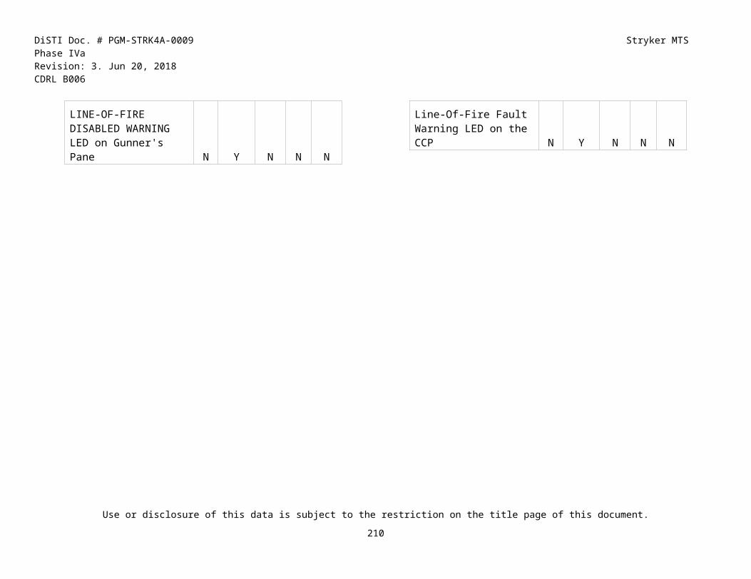
DiSTI Doc. # PGM-STRK4A-0009 Stryker MTS Phase IVaRevision: 3. Jun 20, 2018 CDRL B006
ID IETM Navigation System Symptom Fault Description Faulty Component
Troubleshooting Path
F011
Troubleshooting Procedures --> Field - Troubleshooting Procedure --> REMOTE WEAPON SYSTEM TROUBLESHOOTING
Remote Weapon System
THERMAL IMAGING MODULE INFORMATION NOT PRESENT OR TIM: FCU: VIDEO UNDERLAY CARD REPORTS CAMERA VIDEO MISSING OR TIM: SSA: THERMAL IMAGING MODULE REPORTS INTERNAL FAILURE OR TIM: SSA: THERMAL IMAGING MODULE: COMMUNICATION FAILURE OR SYSTEM STATUS MESSAGE: THERMAL IMAGING MODULE - ERROR OR TIM: FCU: VIDEO PROCESSOR UNIT REPORTS CAMERA VIDEO MISSING
Thermal imaging module information not present
Replace Wiring Harness W16 (Message 1)
TIM Video is Not Functional Using FCU and CG, Yes, Replace Wiring Harness W16, No
F012
Troubleshooting Procedures --> Field - Troubleshooting Procedure --> REMOTE WEAPON SYSTEM TROUBLESHOOTING
Remote Weapon System
UNABLE TO CHANGE VISUAL IMAGING MODULE VIDEO POLARITY OR UNABLE TO CHANGE THERMAL IMAGING MODULE VIDEO POLARITY
Unable to change Thermal Imaging Module Video Polarity
Replace FCU No, Replace FCU, Yes
F013
Troubleshooting Procedures --> Field - Troubleshooting Procedure --> REMOTE WEAPON SYSTEM TROUBLESHOOTING
Remote Weapon System
UNABLE TO CHANGE VISUAL IMAGING MODULE FOCUS OR VIM: SSA: VISIBLE IMAGING MODULE: INVALID FOCUS
Unable to change Visual Imaging Module Focus
Replace VIM Option #4, Replace VIM, Replace VIM, No
F014
Troubleshooting Procedures --> Field - Troubleshooting Procedure --> REMOTE WEAPON SYSTEM TROUBLESHOOTING
Remote Weapon System
UNABLE TO CHANGE VISUAL IMAGING MODULE FOCUS OR VIM: SSA: VISIBLE IMAGING MODULE: INVALID FOCUS
Unable to change Visual Imaging Module Focus
Replace FCU Option #2, Replace FCU, Replace FCU, No
Use or disclosure of this data is subject to the restriction on the title page of this document.
211

DiSTI Doc. # PGM-STRK4A-0009 Stryker MTS Phase IVaRevision: 3. Jun 20, 2018 CDRL B006
ID IETM Navigation System Symptom Fault Description Faulty Component
Troubleshooting Path
F015
Remote Weapon System
UNABLE TO CHANGE ZOOM FACTOR ON VISUAL IMAGING MODULE
Unable to change zoom factor on Visual Imaging Module
Replace FCU
F016
Remote Weapon System
UNABLE TO CONTROL THERMAL IMAGING MODULE GAIN
Unable to control Thermal Imaging Module Gain
Replace FCU
F017
Troubleshooting Procedures --> Field - Troubleshooting Procedure --> REMOTE WEAPON SYSTEM TROUBLESHOOTING
Remote Weapon System
VEHICLE IDENTIFICATION IS NOT CORRECT OR SYSTEM STATUS MESSAGE: VEHICLE ID - UNKNOWN VEHICLE TYPE
Vehicle Identification is not Correct
Replace FCU No, No, Perform Offset, Pass, Test 91, Pass, Replace FCU, Yes
F018
Remote Weapon System
VISUAL IMAGING MODULE INFORMATION NOT PRESENT
Visual Imaging Module Information not present
Replace FCU
F019
Troubleshooting Procedures --> Field - Troubleshooting Procedure --> REMOTE WEAPON SYSTEM TROUBLESHOOTING
Remote Weapon System
VISUAL IMAGING MODULE INFORMATION NOT PRESENT OR SYSTEM STATUS MESSAGE: VISIBLE IMAGING MODULE - ERROR OR VIM: FCU: VIDEO UNDERLAY CARD REPORTS CAMERA VIDEO MISSING OR VIM: SSA: VISIBLE IMAGING MODULE: COMMUNICATION FAILURE OR VIM: FCU: VIDEO PROCESSOR UNIT REPORTS CAMERA VIDEO MISSING
Visual Imaging Module Information not present
Replace VIM (No Message)
Option #3, Option #3, Replace VIM, No
Use or disclosure of this data is subject to the restriction on the title page of this document.
212

DiSTI Doc. # PGM-STRK4A-0009 Stryker MTS Phase IVaRevision: 3. Jun 20, 2018 CDRL B006
ID IETM Navigation System Symptom Fault Description Faulty Component
Troubleshooting Path
F020
Troubleshooting Procedures --> Field - Troubleshooting Procedure --> REMOTE WEAPON SYSTEM TROUBLESHOOTING
Remote Weapon System
VISUAL IMAGING MODULE INFORMATION NOT PRESENT OR SYSTEM STATUS MESSAGE: VISIBLE IMAGING MODULE - ERROR OR VIM: FCU: VIDEO UNDERLAY CARD REPORTS CAMERA VIDEO MISSING OR VIM: SSA: VISIBLE IMAGING MODULE: COMMUNICATION FAILURE OR VIM: FCU: VIDEO PROCESSOR UNIT REPORTS CAMERA VIDEO MISSING
Visual Imaging Module Information not present
Replace VIM and SSA
Option #3, Option #1, Replace VIM, Yes, Replace SSA, No
F021
Remote Weapon System
VISUAL IMAGING MODULE INFORMATION NOT PRESENT
Visual Imaging Module Information not present
Replace VIM (Message 2)
F022
Remote Weapon System
VISUAL IMAGING MODULE INFORMATION NOT PRESENT
Visual Imaging Module Information not present
Replace VIM (Message 3)
F023
Troubleshooting Procedures --> Field - Troubleshooting Procedure --> REMOTE WEAPON SYSTEM TROUBLESHOOTING
Remote Weapon System
WEAPON DOES NOT COCK ELECTRICALLY OR SM: CALIBRATION FAILED. PUSH COCKING ACTUATOR TO FORWARD POSITION OR SM: COCKING ACTUATOR FAILURE
Weapon does not cock Electronically
Replace Cocking Actuator
Option #4, Replace Cocking Actuator, Replace Cocking Actuator, Yes
F024
Remote Weapon System
LRF: SSA: LASER RANGE FINDER REPORTS POWER ERROR
Laser Range Finder Reports Power Error
Laser Range Finder(LRF)
F025
Remote Weapon System
LRF: SSA: LASER RANGE FINDER COMMUNICATION FAILURE
Laser Range Finder Communication Failure
Laser Range Finder(LRF)
Use or disclosure of this data is subject to the restriction on the title page of this document.
213

DiSTI Doc. # PGM-STRK4A-0009 Stryker MTS Phase IVaRevision: 3. Jun 20, 2018 CDRL B006
ID IETM Navigation System Symptom Fault Description Faulty Component
Troubleshooting Path
F026
Troubleshooting Procedures --> Field - Troubleshooting Procedure --> REMOTE WEAPON SYSTEM TROUBLESHOOTING
Remote Weapon System
LOW AMMO SENSOR MALFUNCTION Low Ammo Sensor Malfunction
Low Ammo Sensor
NO, NO, NO, Perform Offset-Pass, Pass, Pass, Fail, Perform Offset-Pass, Fail, Fail, Replace Low Ammo Sensor, Yes
Use or disclosure of this data is subject to the restriction on the title page of this document.
214

DiSTI Doc. # PGM-STRK4A-0009 Stryker MTS Phase IVaRevision: 3. Jun 20, 2018 CDRL B006
APPENDIX G RWS MAINTENANCEProcedures supported in the Phase IVa DTT have data in the IETM Navigation column and correspond to the IAV TM dated 10 Dec 2015. Other procedures are included for reference only but have not been updated and are not supported in the Phase IVa DTT.
ID IETM Navigation System Symptom Faulty ComponentG00
1 Remote
Weapon System
MAIN FRAME CLUTCH ARM ASSEMBLY ADJUSTMENT
Adjust Azimuth on Clutch
G002
Maintenance Procedures --> Field - Maintenance Procedures --> 34 Armament and Sighting and Fire Control (Electric/Electronic) Material --> 3401 REMOTE WEAPONS SYSTEM
Remote Weapon System
SOFT MOUNT ASSEMBLY REPLACEMENT
Replace Soft Mount
G003
Maintenance Procedures --> Field - Maintenance Procedures --> 34 Armament and Sighting and Fire Control (Electric/Electronic) Material --> 3401 REMOTE WEAPONS SYSTEM
Remote Weapon System
LEFT SIDE SUPPORT ASSEMBLY REPLACEMENT
Replace Left Frame Assy
G004
Maintenance Procedures --> Field - Maintenance Procedures --> 34 Armament and Sighting and Fire Control (Electric/Electronic) Material --> 3401 REMOTE WEAPONS SYSTEM
Remote Weapon System
RIGHT SIDE SUPPORT ASSEMBLY REPLACEMENT
Replace Right Frame Assy
G005
Maintenance Procedures --> Field - Maintenance Procedures --> 34 Armament and Sighting and Fire Control (Electric/Electronic) Material --> 3401 REMOTE WEAPONS SYSTEM
Remote Weapon System
MAIN FRAME ASSEMBLY REPLACEMENT
Replace Main Frame Assy
G006
Maintenance Procedures --> Field - Maintenance Procedures --> 34 Armament and Sighting and Fire Control (Electric/Electronic) Material --> 3401 REMOTE WEAPONS SYSTEM
Remote Weapon System
THERMAL IMAGING MODULE REPLACEMENT
Replace TIM
G007
Maintenance Procedures --> Field - Maintenance Procedures --> 34 Armament and Sighting and Fire Control (Electric/Electronic) Material --> 3401 REMOTE WEAPONS SYSTEM
Remote Weapon System
VISUAL IMAGING MODULE REPLACEMENT (041)
Replace VIM
G008
Maintenance Procedures --> Field - Maintenance Procedures --> 34 Armament and Sighting and Fire Control (Electric/Electronic) Material --> 3401 REMOTE WEAPONS SYSTEM
Remote Weapon System
FIRE CONTROL UNIT REPLACEMENT
Replace FCU
Use or disclosure of this data is subject to the restriction on the title page of this document.
215

DiSTI Doc. # PGM-STRK4A-0009 Stryker MTS Phase IVaRevision: 3. Jun 20, 2018 CDRL B006
ID IETM Navigation System Symptom Faulty ComponentG00
9Maintenance Procedures --> Field - Maintenance Procedures --> 34 Armament and Sighting and Fire Control (Electric/Electronic) Material --> 3401 REMOTE WEAPONS SYSTEM
Remote Weapon System
SIGHT SERVO ASSEMBLY REPLACEMENT
Replace SSA
G010
Remote Weapon System
REMOTE WEAPON STATION REPLACEMENT
Replace RWS
G011
Maintenance Procedures --> Field - Maintenance Procedures --> 34 Armament and Sighting and Fire Control (Electric/Electronic) Material --> 3401 REMOTE WEAPONS SYSTEM
Remote Weapon System
COCKING ACTUATOR REPLACEMENT
Replace Cocking Actuator
G012
Maintenance Procedures --> Field - Maintenance Procedures --> 34 Armament and Sighting and Fire Control (Electric/Electronic) Material --> 3401 REMOTE WEAPONS SYSTEM
Remote Weapon System
CONTROL GRIP REPLACEMENT
Replace Control Grip
G013
Remote Weapon System
STORM LASER RANGE FINDER ADJUSTMENT (RWS-I)
Adjust STORM LASER Range Finder
G014
Remote Weapon System
STORM LASER RANGE FINDER REPLACEMENT (RWS-I)
Replace STORM LASER Range Finder
G015
Remote Weapon System
LOW AMMO SENSOR REPLACEMENT (RWS-I)
Replace Low Ammo Sensor
Use or disclosure of this data is subject to the restriction on the title page of this document.
216

DiSTI Doc. # PGM-STRK4A-0009 Stryker MTS Phase IVaRevision: 3. Jun 20, 2018 CDRL B006
APPENDIX H ATGM TROUBLESHOOTINGProcedures supported in the Phase IVa DTT have data in the IETM Navigation and Troubleshooting Path column and correspond to the IAV TM dated 10 Dec 2015. Other procedures are included for reference only but have not been updated and are not supported in the Phase IVa DTT.
ID IETM Navigation System Symptom Fault Description Faulty Component
Troubleshooting Path
H001
Troubleshooting Procedures --> Field Troubleshooting Procedure --> TURRET INTERFACE TROUBLESHOOTING
Turret Interface
AZIMUTH DRIVE TRAVERSES WITHOUT COMMAND
Azimuth Drive Traverses Without Command
Replace CRA Yes, Perform Offset, Pass, Test 91, Fail, Test 91, Fail, Replace CRA.
H002
Troubleshooting Procedures --> Field Troubleshooting Procedure --> TURRET INTERFACE TROUBLESHOOTING
Turret Interface
BATTERY POWER SOURCE (BPS) FAILS TO POWER ON
BPS Fails to Power On Replace BPS No, Option 2, No, Yes, No, Test 89, Pass, Test 89, Pass, Test 89, Pass, Test 89, Pass, Test 89, Pass, Test 89, Pass, Test 89, Pass, Test 89, Pass, Replace BPS.
H003
Troubleshooting Procedures --> Field Troubleshooting Procedure --> -FAULT CODE INDEX
Turret Interface
FAULT CODE INDEX - CHASSIS --> 0000 7F70
CRA Aux Master Power Low
Replace PDA No, No, Yes, Test 89, Fail, Test 89, Fail, Test 89, Fail, Test 89, Pass, Replace PDA, No
H004
Troubleshooting Procedures --> Field Troubleshooting Procedure --> -FAULT CODE INDEX
Turret Interface
FAULT CODE INDEX - CHASSIS --> 0000 7504
CRA MITAS Power Pack Relay Failure
Replace GPA No, No, Perform Offset, Pass, Test 91, Pass, Test 91, Pass, Test 91, Fail, Perform Offset, Pass, Test 91, Fail, Test 91, Fail, Test 91, Pass, Test 91, Pass, Test 91, Fail, Test 91, Fail, Perform Offset, Pass, Test 91, Pass, Replace GPA.
Use or disclosure of this data is subject to the restriction on the title page of this document.
217

DiSTI Doc. # PGM-STRK4A-0009 Stryker MTS Phase IVaRevision: 3. Jun 20, 2018 CDRL B006
ID IETM Navigation System Symptom Fault Description Faulty Component
Troubleshooting Path
H005
Troubleshooting Procedures --> Field - Troubleshooting Procedure --> TURRET INTERFACE TROUBLESHOOTING
Turret Interface
COMMANDER'S PANEL ASSEMBLY LAMP TEST FAILED
CPA Lamp Test Failed Replace CPA No, No, Perform Offset, Pass, Test 91, Pass, Test 91, Fail, Replace CPA, Yes
H006
Turret Interface
COMMANDER'S PANEL ASSEMBLY (CPA) OVERRIDE CONTROLS FAILED
CPA Override Controls Failed
Replace CRA Option 3, No, Perform Offset, Pass, Test 91, Pass, Test 91, Pass, Replace CRA
H007
Troubleshooting Procedures --> Field Troubleshooting Procedure --> -FAULT CODE INDEX
Turret Interface
-FAULT CODE INDEX - CHASSIS --> 0000 7F06
Elevation Motor Controller Failure
Replace CRA No, Perform Offset, Pass, Test 91, Pass, Test 91, Fail, Replace CRA, No
H008
Troubleshooting Procedures --> Field Troubleshooting Procedure --> -FAULT CODE INDEX
Turret Interface
FAULT CODE INDEX - CHASSIS --> 0000 7F60
Elevation Resolver Failure
Replace Resolver
No, No, Perform Offset, Pass, Test 91, Pass, Test 91, Pass, Test 91, Fail, Perform Offset, Pass, Test 91, Fail, Test 91, Fail, Test 91, Fail, Perform Offset, Pass, Test 91, Pass, Test 91, Pass, Test 91, Fail, Perform Offset, Pass, Test 91, Fail, Test 91, Fail, Test 91, Fail, Perform Offset, Pass, Test 91, Pass, Test 91, Pass, Test 91, Fail, Perform Offset, Pass, Test 91, Fail, Test 91, Fail, Test 91, Fail, Perform Offset, Test 91, Pass, Test 91, Pass, Test 91, Fail, Perform Offset, Pass, Test 91, Fail, Test 91, Fail, Test 91, Fail, Replace Resolver, No
Use or disclosure of this data is subject to the restriction on the title page of this document.
218

DiSTI Doc. # PGM-STRK4A-0009 Stryker MTS Phase IVaRevision: 3. Jun 20, 2018 CDRL B006
ID IETM Navigation System Symptom Fault Description Faulty Component
Troubleshooting Path
H009
Turret Interface
ERROR MESSAGE: FCS OVERHEAT- ATTEMPTS FCS COOLDOWN
Error Message: FCS Overheat- Attempts FCS Cooldown
Replace FCS Yes, Yes, Replace FCS
H010
Troubleshooting Procedures --> Field Troubleshooting Procedure --> TURRET INTERFACE TROUBLESHOOTING
Turret Interface
FIRE CONTROL SUBSYSTEM (FCS) MALFUNCTION ICON DISPLAYED
FCS Malfunction Icon Displayed
Replace FCS No, No, No, Yes, Replace FCS, No
H011
Troubleshooting Procedures --> Field - Troubleshooting Procedure --> TURRET INTERFACE TROUBLESHOOTING
Turret Interface
GUNNER CANNOT SET PLATFORM TO LOAD
Gunner Cannot set Platform to Load
Replace CRA No, Perform Offset, Pass, Test 91, Pass, No, Test 91, Pass, Test 91, Fail, Perform Offset, Pass, Test 91, Fail, Replace CRA, Yes
H012
Troubleshooting Procedures --> Field Troubleshooting Procedure --> -FAULT CODE INDEX
Turret Interface
-FAULT CODE INDEX - CHASSIS --> 0000 77B1
Gunner Gyro Switch Failure
Replace GPA No, Perform Offset, Pass, Test 91, Pass, Test 91, Pass, Test 91, Fail, Perform Offset, Pass, Test 91, Fail, Test 91, Fail, Test 91, Pass, Perform Offset, Pass, Test 91, Pass, Test 91, Fail, Test 91, Fail, Perform Offset, Pass, Test 91, Pass, Replace GPA, No
H013
Turret Interface
GUNNER'S HANDLE GRIPS TEST FAILED
Gunner's Handle Grips Test Failed
Replace CRA
H014
Troubleshooting Procedures --> Field Troubleshooting Procedure --> -FAULT CODE INDEX
Turret Interface
FAULT CODE INDEX - CHASSIS --> 0000 7D01
Gunner's Handle's palm Switch Fail on Continuously
Replace CRA No, Perform Offset, Pass, Test 91, Fail, Test 91, Fail, Test 91, Fail, Perform Offset, Pass, Test 91, Fail, Test 91, Fail, Test 91, Fail, Perform Offset, Pass, Test 91, Fail, Test 91, Fail, Replace CRA, No
Use or disclosure of this data is subject to the restriction on the title page of this document.
219

DiSTI Doc. # PGM-STRK4A-0009 Stryker MTS Phase IVaRevision: 3. Jun 20, 2018 CDRL B006
ID IETM Navigation System Symptom Fault Description Faulty Component
Troubleshooting Path
H015
Turret Interface
GUNNER'S PANEL ASSEMBLY (GPA) LAMP TEST FAILED
GPA Lamp Test Failed Replace CRA
H016
Turret Interface
GUNNER'S PANEL ASSEMBLY (GPA) LAMP TEST FAILED
GPA Lamp Test Failed Replace GPA
H017
Turret Interface
INCORRECT OR NO AZIMUTH INDICATION
Incorrect or no Azimuth Indication
Replace APA
H018
Turret Interface
LASER RANGE FINDER RANGE (LRF) NOT DISPLAYED
LRF Range not Displayed
Replace TAS
H019
Turret Interface
LASER RANGE FINDER RANGE (LRF) NOT DISPLAYED
LRF Range not Displayed
Replace FCS
H020
Troubleshooting Procedures --> Field Troubleshooting Procedure --> TURRET INTERFACE TROUBLESHOOTING
Turret Interface
LOADER CANNOT CONTROL PLATFORM
Loader Cannot Control Platform
Replace LPA Option 6, Perform Offset, Pass, Test 91, Fail, Test 91, Pass, Replace LPA.
H021
Troubleshooting Procedures --> Field Troubleshooting Procedure --> TURRET INTERFACE TROUBLESHOOTING
Turret Interface
LOADER CANNOT CONTROL PLATFORM
Loader Cannot Control Platform
Replace CRA Option 6, Perform Offset, Pass, Test 91, Fail, Test 91, Fail, Replace CRA.
H022
Turret Interface
LOADER'S CONTROL PANEL LAMP TEST FAILED
Loader's Control Panel Lamp Test Failed
Replace CRA
Use or disclosure of this data is subject to the restriction on the title page of this document.
220

DiSTI Doc. # PGM-STRK4A-0009 Stryker MTS Phase IVaRevision: 3. Jun 20, 2018 CDRL B006
ID IETM Navigation System Symptom Fault Description Faulty Component
Troubleshooting Path
H023
Turret Interface
LOADER'S CONTROL PANEL LAMP TEST FAILED
Loader's Control Panel Lamp Test Failed
Replace LPA
H024
Troubleshooting Procedures --> Field Troubleshooting Procedure --> TURRET INTERFACE TROUBLESHOOTING
Turret Interface
LOSS OF POWER AT GUNNER'S DISPLAY ASSEMBLY
Loss of Power at Gunner's Display Assembly
Replace PDA No, Yes, No, No, Perform Offset, Pass, Test 91, Pass, Test 91, Pass, Test 91, Fail, Perform Offset, Pass, Test 91, Fail Yes, Replace PDA.
H025
Turret Interface
MAST LIMIT SWITCH FAILURE 1, FAULT CODE 0000 7740
Mast Limit Switch Failure 1
Replace Lower Limit Switch
H026
Turret Interface
MAST LIMIT SWITCH FAILURE 2, FAULT CODE 0000 7F40
Mast Limit Switch Failure 2
Replace CRA
H027
Turret Interface
MAST MOTOR CONTROLLER FAILURE, FAULT CODE 0000 7F0A
Mast Motor Controller Failure
Replace CRA
H028
Turret Interface
MOTOR CONTROLLER DIRECT CURRENT CONVERTER FAILURE, FAULT CODE 0000 7F00
Motor Controller DC Converter Failure
Replace CRA
H029
Turret Interface
MOTOR CONTROLLER DIRECT CURRENT CONVERTER TEMPERATURE HIGH, FAULT CODE 0000 7F01
Motor Controller DC Converter Temperature High
Replace CRA No, Test 89, Fail, Replace CRA
Use or disclosure of this data is subject to the restriction on the title page of this document.
221

DiSTI Doc. # PGM-STRK4A-0009 Stryker MTS Phase IVaRevision: 3. Jun 20, 2018 CDRL B006
ID IETM Navigation System Symptom Fault Description Faulty Component
Troubleshooting Path
H030
Troubleshooting Procedures --> Field Troubleshooting Procedure --> TURRET INTERFACE TROUBLESHOOTING
Turret Interface
MOTOR TEMP LED ILLUMINATED
Motor Temp LED Illuminated
Replace CRA Option 2, No, Perform Offset, Pass, Test 91, Pass, Test 89, Pass, Perform Offset, Pass, Test 91, Pass, Test 91, Pass, Replace CRA.
H031
Troubleshooting Procedures --> Field - Troubleshooting Procedure --> TURRET INTERFACE TROUBLESHOOTING
Turret Interface
NIGHT VISION SYSTEM NOT COOL ICON DISPLAYED
Night Vision System NOT COOL Icon Displayed
Replace TAS Yes, Yes, No, Replace TAS, Yes
H032
Troubleshooting Procedures --> Field Troubleshooting Procedure --> TURRET INTERFACE TROUBLESHOOTING
Turret Interface
NO POWER AT PRIMARY WEAPON STATION
No Power at Primary Weapon Station
Replace PDA No, Yes, Yes, No, Perform Offset, Pass, Test 91, Pass, Test 91, Fail, Test 91, Pass, Perform Offset, Pass, Test 91, Pass, Test 91, Fail, Test 91, Fail, Replace PDA.
H033
Turret Interface
PLATFORM DEPRESSES/ELEVATES WITHOUT COMMAND
Platform Depresses/Elevates Without Command
Replace Gunner's Handles
Yes, No, Perform Offset, Pass, Test 91, Fail, Test 91, Fail, Replace Gunner’s Handles
H034
Turret Interface
PLATFORM MODE SWITCH FAILURE 1, FAULT CODE 0000 77B0
Platform Mode Switch Failure 1
Replace GPA No, Perform Offset, Pass, Test 91, Pass, Test 91, Pass, Test 91, Fail, Perform Offset, Pass, Test 91, Fail, Test 91, Fail, Test 91, Fail, Perform Offset, Pass, Test 91, Pass, Test 91, Pass, Test 91, Pass, Perform Offset, Pass, Test 91, Pass, Test 91, Fail, Test 91, Fail, Perform Offset, Pass, Test 91, Fail, Test 91, Pass, Replace GPA
Use or disclosure of this data is subject to the restriction on the title page of this document.
222

DiSTI Doc. # PGM-STRK4A-0009 Stryker MTS Phase IVaRevision: 3. Jun 20, 2018 CDRL B006
ID IETM Navigation System Symptom Fault Description Faulty Component
Troubleshooting Path
H035
Troubleshooting Procedures --> Field Troubleshooting Procedure --> -FAULT CODE INDEX
Turret Interface
-FAULT CODE INDEX - CHASSIS --> 0000 7FB0
Platform Mode Switch Failure 2
Replace GPA No, Perform Offset, Pass, Test 91, Fail, Test 91, Fail, Test 91, Fail, Perform Offset, Pass, Test 91, Pass, Replace GPA, No
H036
Troubleshooting Procedures --> Field Troubleshooting Procedure --> TURRET INTERFACE TROUBLESHOOTING
Turret Interface
PLATFORM WILL NOT STABILIZE
Platform will not Stabilize
Replace CRA No, Option 1, No, No, Perform Offset, Pass, Test 91, Pass, Test 91, Pass, No, Test 91, Pass, Perform Offset, Pass, Test 91, Pass, Test 91, Pass, Test 91, Pass, Test 91, Pass, Test 91, Pass, No, Perform Offset, Pass, Test 91, Pass, Test 91, Pass, Test 91, Pass, Replace CRA.
H037
Troubleshooting Procedures --> Field Troubleshooting Procedure --> -FAULT CODE INDEX
Turret Interface
-FAULT CODE INDEX - CHASSIS --> 0000 7F05
PEU Azimuth Tachometer Offset Failure
Replace CRA No, No, Perform Offset, Pass, Test 91, Fail, Test 91, Fail, Test 91, Fail, Perform Offset, Pass, Test 91, Fail, Test 91, Fail, Test 91, Fail, Perform Offset, Pass, Test 91, Fail, Test 91, Fail, Replace CRA, No
H038
Troubleshooting Procedures --> Field Troubleshooting Procedure --> -FAULT CODE INDEX
Turret Interface
-FAULT CODE INDEX - CHASSIS --> 0000 7FE3
Power Transfer Assembly Elevation Relay Disable Failure
Replace CRA No, Perform Offset, Pass, Test 91, Pass, Test 91, Pass, Test 91, Fail, Perform Offset, Pass, Test 91, Fail, Replace CRA, No
H039
Troubleshooting Procedures --> Field Troubleshooting Procedure --> -FAULT CODE INDEX
Turret Interface
-FAULT CODE INDEX - CHASSIS --> 0000 7FE2
Power Transfer Assembly Mast Relay Disable Failure
Replace CRA No, Perform Offset, Pass, Test 91, Pass, Test 91, Pass, Test 91, Fail, Perform Offset, Pass, Test 91, Fail, Replace CRA, No
H040
Turret Interface
SIGHT DOOR FAILS TO OPEN, FAULT CODE 0000 77E1
Sight Door Fails to Open
Replace CRA No, Yes, No, No, No, Perform Offset, Pass, Test 91, Pass, Test 91, Pass, Test 91, Pass, Perform Offset, Pass, Test 91, Pass, Test 91, Pass, Replace CRA
Use or disclosure of this data is subject to the restriction on the title page of this document.
223

DiSTI Doc. # PGM-STRK4A-0009 Stryker MTS Phase IVaRevision: 3. Jun 20, 2018 CDRL B006
ID IETM Navigation System Symptom Fault Description Faulty Component
Troubleshooting Path
H041
Turret Interface
TARGET ACQUISITION SYSTEM (TAS) COOLING FAN FAILURE, FAULT CODE 0000 7780
TAS Cooling Fan Failure
Replace W224
No, No, No, No, No, Test 89, Fail, Test 89, Pass, Test 89, Pass, Test 89, Pass, Test 89, Pass, Test 89, Pass, Test 89, Pass, Replace W224
H042
Turret Interface
TARGET ACQUISITION SYSTEM (TAS) COOLING FAN FAILURE, FAULT CODE 0000 7780
TAS Cooling Fan Failure
Replace TAS Cooling Fan
No, Yes, No, No, Perform Offset, Pass, Test 91, Pass, Test 91, Fail, Test 91, Fail, Perform Offset, Pass, Test 91, Pass, Test 91, Fail, Test 91, Pass, Perform Offset, Pass, Test 91, Fail, Test 91, Pass, Test 91, Fail, Replace TAS Cooling Fan
H043
Troubleshooting Procedures --> Field - Troubleshooting Procedure --> TURRET INTERFACE TROUBLESHOOTING
Turret Interface
TARGET ACQUISITION SYSTEM MALFUNCTION ICON DISPLAYED
TAS Malfunction Icon Displayed
Replace TAS No, No, No, Replace TAS, Yes
H044
Troubleshooting Procedures --> Field Troubleshooting Procedure --> -FAULT CODE INDEX
Turret Interface
FAULT CODE INDEX - CHASSIS --> 0000 7729
TOW Extend Umbilical Failure
Replace CRA No, No, No, No, Perform Offset, Pass, Test 91, Pass, Test 91, Pass, Test 91, Fail, Perform Offset, Pass, Test 91, Fail, Test 91, Fail, Test 91, Pass, Perform Offset, Pass, Test 91, Pass, Test 91, Fail, Test 91, Fail, Perform Offset, Pass, Test 91, Fail, Test 91, Pass, Test 91, Pass, Perform Offset, Pass, Test 91, Fail, Test 91, Fail, Test 91, Fail, Perform Offset, Pass, Test 91, Pass, Test 91, Pass, Test 91, Fail, Perform Offset, Pass, Test 91, Fail, Test 91, Fail, Test 91, Pass, Perform Offset, Pass, Test 91, Fail, Test 91, Fail, Replace CRA, Continue, Continue, Continue, Continue, No
Use or disclosure of this data is subject to the restriction on the title page of this document.
224

DiSTI Doc. # PGM-STRK4A-0009 Stryker MTS Phase IVaRevision: 3. Jun 20, 2018 CDRL B006
ID IETM Navigation System Symptom Fault Description Faulty Component
Troubleshooting Path
H045
Turret Interface
TOW MISSILE 1 SELECT FAILURE, FAULT CODE 0000 7713
TOW Missile 1 Select Failure
Replace CRA No, No, No, No, Perform Offset, Pass, Test 91, Pass, Test 91, Fail, Test 91, Pass, Perform Offset, Pass, Test 91, Fail, Test 91, Pass, Test 91, Pass, Perform Offset, Pass, Test 91, Fail, Test 91, Fail, Test 91, Fail, Perform Offset, Pass, Test 91, Pass, Test 91, Pass, Test 91, Fail, Perform Offset, Pass, Test 91, Fail, Test 91, Fail, Test 91, Pass, Perform Offset, Pass, Test 91, Pass, Test 91, Fail, Test 91, Fail, Perform Offset, Pass, Test 91, Fail, Test 91, Pass, Test 91, Pass, Perform Offset, Pass, Test 91, Fail, Test 91, Fail, Test 91, Fail, Replace CRA
H046
Turret Interface
TOW MISSILE 2 ARMAMENT CONTROL UNIT ARMING RELAY FAILURE, FAULT CODE 0000 7726
TOW Missile 2 Armament Control Unit Arming Relay Failure
Replace CRA No, No, No, No, Perform Offset, Pass, Test 91, Pass, Test 91, Fail, Test 91, Fail, Perform Offset, Pass, Test 91, Pass, Test 91, Fail, Test 91, Fail, Perform Offset, Pass, Test 91, Pass, Test 91, Fail, Test 91, Fail, Perform Offset, Pass, Test 91, Pass, Test 91, Fail, Test 91, Fail, Perform Offset, Pass, Test 91, Pass, Test 91, Fail, Replace CRA
H047
Turret Interface
TOW MISSILE 2 PRESENT FALSE INDICATION, FAULT CODE 0000 772C
TOW Missile 2 Present False Indication
Replace CRA No, No, No, No, Perform Offset, Pass, Test 91, Pass, Test 91, Fail, Test 91, Fail, Perform Offset, Pass, Test 91, Pass, Test 91, Fail, Test 91, Fail, Perform Offset, Pass, Test 91, Pass, Test 91, Fail, Test 91, Fail, Perform Offset, Pass, Test 91, Pass, Test 91, Fail, Test 91, Fail, Perform Offset, Pass, Test 91, Pass, Test 91, Fail, Test 91, Fail, Replace CRA
Use or disclosure of this data is subject to the restriction on the title page of this document.
225

DiSTI Doc. # PGM-STRK4A-0009 Stryker MTS Phase IVaRevision: 3. Jun 20, 2018 CDRL B006
ID IETM Navigation System Symptom Fault Description Faulty Component
Troubleshooting Path
H048
Turret Interface
TOW MISSILE 2 SQUIB FIRING RELAY FAILURE, FAULT CODE 0000 7728
TOW Missile 2 Squib Firing Relay Failure
Replace TIA No, No, No, No, Perform Offset, Pass, Test 91, Pass, Test 91, Fail, Test 91, Pass, Perform Offset, Pass, Test 91, Fail, Test 91, Pass, Test 91, Fail, Perform Offset, Pass, Test 91, Pass, Test 91, Fail, Perform Offset, Pass, Test 91, Pass, Test 91, Fail, Test 91, Pass, Perform Offset, Pass, Test 91, Pass, Replace TIA
H049
Turret Interface
TOW WIRE CUT FAILURE, FAULT CODE 0000 7723
TOW Wire Cut Failure Replace CRA No, No, No, Perform Offset, Pass, Test 91, Pass, Test 91, Fail, Test 91, Fail, Perform Offset, Pass, Test 91, Pass, Test 91, Fail, Test 91, Fail, Perform Offset, Pass, Test 91, Pass, Test 91, Fail, Test 91, Fail, Perform Offset, Pass, Test 91, Pass, Test 91, Fail, Test 91, Fail, Replace CRA
H050
Turret Interface
TRACK GATE NOT SELECTABLE
Track Gate not Selectable
Replace FCS Yes, No, Replace FCS
H051
Troubleshooting Procedures --> Field Troubleshooting Procedure --> TURRET INTERFACE TROUBLESHOOTING
Turret Interface
UNABLE TO SELECT MENU FUNCTIONS
Unable to Select Menu Function
Replace FCS Yes, No, Replace FCS.
H052
Troubleshooting Procedures --> Field Troubleshooting Procedure --> -FAULT CODE INDEX
Turret Interface
FAULT CODE INDEX - CHASSIS --> 0000 7F07
Elevation Motor Temperature High
Replace CRA Replace CRA No, Perform Offset, Pass, Test 91, Pass, Test 91, Fail, Replace CRA.
Use or disclosure of this data is subject to the restriction on the title page of this document.
226

DiSTI Doc. # PGM-STRK4A-0009 Stryker MTS Phase IVaRevision: 3. Jun 20, 2018 CDRL B006
ID IETM Navigation System Symptom Fault Description Faulty Component
Troubleshooting Path
H053
Turret Interface
TARGET ACQUISITION SYSTEM (TAS) COOLING FAN FAILED
TAS Cooling Fan Failed
Replace CRA No, No, No, No, No, No, No Perform Offset, Pass, Test 91, Pass, Test 91, Fail, Test 91, Fail, Perform Offset, Pass, Test 91, Pass, Test 91, Fail, Test 91, Fail, Yes, Perform Offset, Pass, Test 91, Pass, Test 89, Fail, Perform Offset, Pass, Test 91, Pass, Test 91, Pass, Test 91, Pass, Perform Offset, Pass, Test 91, Fail, Test 91, Fail, Test 91, Fail, Perform Offset, Pass, Test 91, Fail, Test 91, Fail, Test 91, Fail, Test 89, Pass, Perform Offset, Pass, Test 91, Pass, Test 91, Pass, Test 91, Fail, Perform Offset, Pass, Test 91, Fail, Test 91, Pass, Test 91, Pass, Perform Offset, Pass, Test 91, Pass, Test 91, Fail, Test 91, Fail, Perform Offset, Pass, Test 91, Fail, Test 91, Fail, Test 91, Fail, Perform Offset, Pass, Test 91, Fail, Test 91, Fail, Test 91, Pass, Perform Offset, Pass, Test 91, Pass, Test 91, Fail, Test 91, Fail, Perform Offset, Pass, Test 91, Pass, Test 91, Fail, Test 91, Fail, Replace CRA
Use or disclosure of this data is subject to the restriction on the title page of this document.
227

DiSTI Doc. # PGM-STRK4A-0009 Stryker MTS Phase IVaRevision: 3. Jun 20, 2018 CDRL B006
APPENDIX I ATGM MAINTENANCEProcedures supported in the Phase IVa DTT have data in the IETM Navigation column and correspond to the IAV TM dated 10 Dec 2015. Other procedures are included for reference only but have not been updated and are not supported in the Phase IVa DTT.
ID IETM Navigation System Symptom Faulty ComponentI001 Maintenance Procedures --> Field - Maintenance Procedures --> 34
Armament and Sighting and Fire Control (Electric/Electronic) Material --> 3406 TOW WEAPONS SYSTEM
Turret Interface
AZIMUTH POSITION ASSEMBLY REPLACEMENT
Replace Azimuth Position Assembly (APA)
I002 Maintenance Procedures --> Field - Maintenance Procedures --> 34 Armament and Sighting and Fire Control (Electric/Electronic) Material --> 3406 TOW WEAPONS SYSTEM
Turret Interface
BATTERY POWER SUPPLY REPLACEMENT
Replace Battery Power Supply (BPS)
I003 Maintenance Procedures --> Field - Maintenance Procedures --> 34 Armament and Sighting and Fire Control (Electric/Electronic) Material --> 3406 TOW WEAPONS SYSTEM
Turret Interface
CARD RACK ASSEMBLY REPLACEMENT
Replace Card Rack Assembly (CRA)
I004 Maintenance Procedures --> Field - Maintenance Procedures --> 34 Armament and Sighting and Fire Control (Electric/Electronic) Material --> 3406 TOW WEAPONS SYSTEM
Turret Interface
COMMANDER'S PANEL ASSEMBLY REPLACEMENT
Replace Commander’s Panel Assembly (CPA)
I005 Maintenance Procedures --> Field - Maintenance Procedures --> 34 Armament and Sighting and Fire Control (Electric/Electronic) Material --> 3406 TOW WEAPONS SYSTEM
Turret Interface
FIRE CONTROL SYSTEM REPLACEMENT
Replace Fire Control System (FCS)
I006 Maintenance Procedures --> Field - Maintenance Procedures --> 34 Armament and Sighting and Fire Control (Electric/Electronic) Material --> 3406 TOW WEAPONS SYSTEM
Turret Interface
GUNNER'S DISPLAY ASSEMBLY REPLACEMENT
Replace Gunner’s Display Assembly (GDA)
I007 Maintenance Procedures --> Field - Maintenance Procedures --> 34 Armament and Sighting and Fire Control (Electric/Electronic) Material --> 3406 TOW WEAPONS SYSTEM
Turret Interface
GUNNER'S HANDLE REPLACEMENT Replace Gunner’s Handle
I008 Maintenance Procedures --> Field - Maintenance Procedures --> 34 Armament and Sighting and Fire Control (Electric/Electronic) Material --> 3406 TOW WEAPONS SYSTEM
Turret Interface
GUNNER'S PANEL ASSEMBLY REPLACEMENT
Replace Gunner’s Panel Assembly (GPA)
I009 Maintenance Procedures --> Field - Maintenance Procedures --> 34 Armament and Sighting and Fire Control (Electric/Electronic) Material --> 3406 TOW WEAPONS SYSTEM
Turret Interface
GYRO ASSEMBLY REPLACEMENT Replace Gyro
Use or disclosure of this data is subject to the restriction on the title page of this document.
228

DiSTI Doc. # PGM-STRK4A-0009 Stryker MTS Phase IVaRevision: 3. Jun 20, 2018 CDRL B006
ID IETM Navigation System Symptom Faulty ComponentI010 Maintenance Procedures --> Field - Maintenance Procedures --> 34
Armament and Sighting and Fire Control (Electric/Electronic) Material --> 3406 TOW WEAPONS SYSTEM
Turret Interface
LOADER'S PANEL REPLACEMENT Replace Loader’s Panel (LPA)
I011 Maintenance Procedures --> Field - Maintenance Procedures --> 34 Armament and Sighting and Fire Control (Electric/Electronic) Material --> 3406 TOW WEAPONS SYSTEM
Turret Interface
Mast Limit Switch Replacement Replace Lower Limit Switch
I012 Maintenance Procedures --> Field - Maintenance Procedures --> 34 Armament and Sighting and Fire Control (Electric/Electronic) Material --> 3406 TOW WEAPONS SYSTEM
Turret Interface
POWER DISTRIBUTION ASSEMBLY REPLACEMENT
Replace Power Distribution Assembly (PDA)
I013 Maintenance Procedures --> Field - Maintenance Procedures --> 34 Armament and Sighting and Fire Control (Electric/Electronic) Material --> 3406 TOW WEAPONS SYSTEM
Turret Interface
RESOLVER REPLACEMENT Replace Resolver
I014 Maintenance Procedures --> Field - Maintenance Procedures --> 34 Armament and Sighting and Fire Control (Electric/Electronic) Material --> 3406 TOW WEAPONS SYSTEM
Turret Interface
TARGET ACQUISITION SYSTEM REPLACEMENT
Replace Target Acquisition System (TAS)
I015 Maintenance Procedures --> Field - Maintenance Procedures --> 34 Armament and Sighting and Fire Control (Electric/Electronic) Material --> 3406 TOW WEAPONS SYSTEM
Turret Interface
TAS COOLING FAN REPLACEMENT Replace TAS Cooling Fan
I016 Maintenance Procedures --> Field - Maintenance Procedures --> 34 Armament and Sighting and Fire Control (Electric/Electronic) Material --> 3406 TOW WEAPONS SYSTEM
Turret Interface
TOW INTERFACE ASSEMBLY REPLACEMENT
Replace TOW Interface Assembly (TIA)
I017 Turret Interface
WIRING HARNESS W224 REPLACEMENT: CONNECTOR PLATE TO TOW PLATFORM
Replace Wiring Harness W224
I018 Maintenance Procedures --> Field - Maintenance Procedures --> 34 Armament and Sighting and Fire Control (Electric/Electronic) Material --> 3406 TOW WEAPONS SYSTEM
Turret Interface
Power Transfer Assembly (PTA) Replacement
Power Transfer Assembly (PTA)
I019 Maintenance Procedures --> Field - Maintenance Procedures --> 34 Armament and Sighting and Fire Control (Electric/Electronic) Material --> 3406 TOW WEAPONS SYSTEM
Turret Interface
Power Electronics Unit (PEU) Replacement
Power Electronics Unit (PEU)
Use or disclosure of this data is subject to the restriction on the title page of this document.
229

DiSTI Doc. # PGM-STRK4A-0009 Stryker MTS Phase IVaRevision: 3. Jun 20, 2018 CDRL B006
APPENDIX J FSV TROUBLESHOOTINGNo FSV procedures are supported in the Phase IVa DTT. A 3D model of the FSV is included in the DTT for basic familiarization only. Legacy FSV procedures listed here are included for reference only but have not been updated and are not supported.
ID IETM Navigation
System Symptom Fault Description Faulty Component
Troubleshooting Path
J001 Fire Support Sensor
LOSS OF AUDIO ALERT FOR FS3 MISSION EQUIPMENT PACKAGE (MEP)
Loss of Audio Alert for FS3 MEP
Replace TSCP
J002 Fire Support Sensor
LOSS OF POWER TO DRIVER'S DISPLAY UNIT
Loss of Power to Driver's Display Unit
Replace PDU
J003 Fire Support Sensor
DELETED - LOSS OF POWER TO FIRE SUPPORT SENSOR SYSTEM (FS3) MEP PLGR
Loss of Power to FS3 MEP PLGR
Replace PDU
J004 Fire Support Sensor
LOSS OF POWER TO FIRE SUPPORT SENSOR SYSTEM (FS3) MEP
Loss of Power to FS3 MEP
Replace PDP
J005 Fire Support Sensor
LOSS OF POWER TO FIRE SUPPORT SENSOR SYSTEM (FS3) MEP
Loss of Power to FS3 MEP
Replace Inline Power Box
No, No, No, Test 89, Fail, Test 89, Fail, Test 89, Fail, Test 89, Fail, Test 89, Pass, Replace Inline Power Box
J006 Fire Support Sensor
LOSS OF POWER TO FIRE SUPPORT SENSOR SYSTEM (FS3)
Loss of Power to FS3 Replace VPC No, No, No, No, No, Perform Offset, Pass, Test 91, Pass, Test 91, Pass, Test 91, Pass, Perform Offset, Pass, Test 91, Pass, Test 91, Pass, Test 91, Pass, Perform Offset, Pass, Test 91, Pass, Test 91, Pass, Test 91, Pass, Perform Offset, Pass, Test 91, Pass, Test 91, Pass, Test 91, Pass, Test 91, Pass, Perform Offset, Pass, Test 91, Pass, Test 91, Pass, Test 91, Pass, Perform Offset, Pass, Test 91, Pass, Test 91, Pass, Test 91, Pass, Perform Offset, Pass, Test 91, Pass, Test 91, Pass, Replace VPC
Use or disclosure of this data is subject to the restriction on the title page of this document.
230

DiSTI Doc. # PGM-STRK4A-0009 Stryker MTS Phase IVaRevision: 3. Jun 20, 2018 CDRL B006
ID IETM Navigation
System Symptom Fault Description Faulty Component
Troubleshooting Path
J007 Fire Support Sensor
LOSS OF POWER TO REMOTE DISPLAY UNIT
Loss of Power to RDU Replace PDU No, No, Test 89, Fail, Test 89, Fail, Test 89, Fail, Replace RDU
J008 Fire Support Sensor
DELETED - LOSS OF POWER TO SINCGARS RADIOS
Loss of Power to SINCGARS Radios
Replace PDU
J009 Fire Support Sensor
LOSS OF POWER TO STANDALONE COMPUTER UNIT (SCU)
Loss of Power to SCU Replace PDU
J010 Fire Support Sensor
LOSS OF POWER TO TARGETING STATION CONTROL PANEL (TSCP)
Loss of Power to TSCP
Replace PDU
J011 Fire Support Sensor
OUT OF TRAVEL LOCK DISPLAYED ON TARGETING STATION CONTROL PANEL (TSCP), WHEN CUPOLA LOCK IS IN LOCKED POSITION
Out of Travel Lock Displayed on TSCP, When Cupola Lock is in Locked Position
Replace TSCP
J012 Fire Support Sensor
POWER LED ON POWER ASSIST ASSEMBLY IS NOT ILLUMINATED WHEN POWER SWITCH IS SET TO ON
Power LED on Power Assist Assembly is not Illuminated When Power Switch is set to ON
Replace PDP
J013 Fire Support Sensor
TARGETING STATION CONTROL PANEL (TSCP) DISPLAYS SYSTEM FAILS INS OR SHOW FAULTS DISPLAYS INS 1553 COMM
TSCP Displays System Fails INS or Show Faults Displays INS 1553 COMM
Replace MPU Yes, No, No, No, No, No, No, Test 89, Pass, Perform Offset, Pass, Test 91, Pass, Test 91, Pass, Test 91, Fail, Perform Offset, Pass, test 91, Fail, Test 91, Fail, Test 91, Fail, Perform Offset, Pass, Test 91, Pass, Test 91, Pass, Test 91, Fail, Perform Offset, Pass, Test 91, Fail, Test 91, Fail, Test 91, Fail, Replace MPU
Use or disclosure of this data is subject to the restriction on the title page of this document.
231

DiSTI Doc. # PGM-STRK4A-0009 Stryker MTS Phase IVaRevision: 3. Jun 20, 2018 CDRL B006
ID IETM Navigation
System Symptom Fault Description Faulty Component
Troubleshooting Path
J014 Fire Support Sensor
TARGETING STATION CONTROL PANEL (TSCP) DISPLAYS SYSTEM FAILS INS OR SHOW FAULTS DISPLAYS INS 1553 COMM
TSCP Displays System Fails INS or Show Faults Displays INS 1553 COMM
Replace PDU
J015 Fire Support Sensor
TARGETING STATION CONTROL PANEL (TSCP) DISPLAYS SYSTEM FAILS VEHICLE NAVIGATION SYSTEM (VNS) ADAPTER BOX
TSCP Displays System Fails VNS Adapter Box
Replace PDU
J016 Fire Support Sensor
TROUBLESHOOT CUPOLA INSTALLATION
Troubleshoot Cupola Installation
Replace PAA No, No, No, No, No, No, Yes, Perform Offset, Pass, Test 91, Pass, Test 91, Pass, Test 91, Pass, Replace PAA
J017 Fire Support Sensor
VIDEO DISPLAY TERMINAL (VDT) NOT DISPLAYING FIRE SUPPORT SENSOR SYSTEM (FS3) VIDEO
VDT not Displaying FS3 Video
Replace VDT
Use or disclosure of this data is subject to the restriction on the title page of this document.
232

DiSTI Doc. # PGM-STRK4A-0009 Stryker MTS Phase IVaRevision: 3. Jun 20, 2018 CDRL B006
APPENDIX K FSV MAINTENANCENo FSV maintenance procedures are supported in the Training Task List for the Phase IVa DTT. Legacy FSV procedures listed here are included for reference only but have not been updated and are not supported. However, procedures indicated by an asterisk ‘*’ in the IETM Navigation column may be performed in free run mode for vehicle overview and familiarity.
ID IETM Navigation
System Symptom Faulty Component
K001
Mission Equipment Package Maintenance
INLINE POWER BOX (IPB) REPLACEMENT Replace Inline Power Box
K002
* Fire Support Sensor MISSION PROCESSOR UNIT REPLACEMENT Replace Mission Processor Unit (MPU)
K003
* Fire Support Sensor POWER ASSIST ASSEMBLY REPLACEMENT Replace Power Assist Assembly (PAA)
K004
* Fire Support Sensor POWER CONDITIONER REPLACEMENT Replace Power Conditioner (VPC)
K006
Fire Support Sensor POWER DISTRIBUTION UNIT (PDU) REPLACEMENT
Replace Power Distribution Unit (PDU)
K007
* Fire Support Sensor REMOTE DISPLAY UNIT REPLACEMENT Replace Remote Display Unit (RDU)
K008
Fire Support Sensor SQUAD LEADER'S VIDEO DISPLAY TERMINAL REPLACEMENT
Replace Squad Leader's Video Display Terminal (VDT)
K009
Fire Support Sensor TARGETING STATION CONTROL PANEL REPLACEMENT
Replace Targeting Station Control Panel (TSCP)
Use or disclosure of this data is subject to the restriction on the title page of this document.
233

DiSTI Doc. # PGM-STRK4A-0009 Stryker MTS Phase IVaRevision: 3. Jun 20, 2018 CDRL B006
APPENDIX L MCV TROUBLESHOOTINGA single troubleshooting procedure is supported in the Phase IVa DTT, indicated by data in the IETM Navigation and Troubleshooting Path column and corresponding to the IAV TM dated 10 Dec 2015. Other procedures are included for reference only but have not been updated and are not supported in the Phase IVa DTT.
ID IETM Navigation System Symptom Fault Description Faulty Component
Troubleshooting Path
L001 Mortar Fire Control
MORTAR FIRE CONTROL SYSTEM (MFCS) DOES NOT OPERATE PROPERLY
Mortar Fire Control System (MFCS) does not operate properly
Replace Wiring Harness W710
Yes, Yes, No, No, No, No, Perform Offset, Pass, Test 91, Pass, Test 91, Pass, Test 91, Pass, Perform Offset, Pass, Test 91, Pass, Test 91, Pass, Replace Wiring Harness W710
L002 Mortar Fire Control
WIRING HARNESS W480-9-B CHECK OUT
Wiring Harness W480-9-B Check Out
Replace W480-9-B
No, Perform Offset, Pass, Test 91, Fail, Test 91, Fail, Test 91, Fail, Perform Offset, Pass, Test 91, Fail, Test 91, Fail, Test 91, Pass, Perform Offset, Pass, Test 91, Pass, Test 91, Pass, Test 91, Pass, Perform Offset, Pass, Test 91, Fail, Replace W480-9-B
L003 Troubleshooting Procedures --> Field - Troubleshooting Procedure --> ARMAMENT, SIGHTING, AND FIRE CONTROL TROUBLESHOOTING
Mortar Fire Control
120MM MORTAR SYSTEM RECUPERATOR HYDRAULIC GAUGE LEVEL LOW
Replace Recuperator Assembly
No, No, No, No, No, No, Replace Recuperator Assembly, Yes
Use or disclosure of this data is subject to the restriction on the title page of this document.
234

DiSTI Doc. # PGM-STRK4A-0009 Stryker MTS Phase IVaRevision: 3. Jun 20, 2018 CDRL B006
APPENDIX M MCV MAINTENANCENo MCV maintenance procedures are supported in the Training Task List for the Phase IVa DTT. Legacy MCV procedures listed here are included for reference only but have not been updated and are not supported. However, procedures indicated by an asterisk ‘*’ in the IETM Navigation column may be performed in free run mode for vehicle overview and familiarization.
ID IETM Navigation
System Symptom Faulty Component
M001
Armament, Sighting, and Fire Control ACCESS DOOR, PLATFORM BASE (LEFT) REPLACEMENT Replace Access Door, Platform Base (Left)
M002
Armament, Sighting, and Fire Control ACCESS DOOR, PLATFORM BASE (RIGHT) REPLACEMENT Replace Access Door, Platform Base (Right)
M003
* Armament, Sighting, and Fire Control BASE AND PINTLE MOUNT ASSEMBLY REPLACEMENT Replace Base & Pintle Mount Assembly
M004
Armament, Sighting, and Fire Control COMMANDER'S INTERFACE (MFCS) REPLACEMENT Replace Commander's Interface (MFCS)
M005
Armament, Sighting, and Fire Control CRADLE ASSEMBLY REPLACEMENT Replace Cradle Assembly
M006
Armament, Sighting, and Fire Control DRIVER'S DISPLAY, PLATES, AND ISOLATORS Replace Driver's Display, Plates, and Isolators
M007
* Armament, Sighting, and Fire Control ELEVATION GEAR ASSEMBLY REPLACEMENT Replace Elevating Gear Assembly
M008
Armament, Sighting, and Fire Control HARNESS W480-9-B REPLACEMENT: TERMINATES AT VMSC, CABLE W710, CABLE W415-9, PPI
Replace Harness W480-9-B
M009
Armament, Sighting, and Fire Control GUNNER'S DISPLAY REPLACEMENT Replace Gunner's Display
M010
Armament, Sighting, and Fire Control POINTING DEVICE REPLACEMENT Replace Pointing Device
M011
Armament, Sighting, and Fire Control POWER DISTRIBUTION ASSEMBLY (PDA) REPLACEMENT Replace PDA
M012
* Armament, Sighting, and Fire Control TRAVERSING GEAR ASSEMBLY REPLACEMENT Replace Traversing Gear Assembly
M013
Armament, Sighting, and Fire Control VEHICLE MOTION SIGNAL CONDITIONER (VMSC) REPLACEMENT
Replace VMSC
Use or disclosure of this data is subject to the restriction on the title page of this document.
235

DiSTI Doc. # PGM-STRK4A-0009 Stryker MTS Phase IVaRevision: 3. Jun 20, 2018 CDRL B006
ID IETM Navigation
System Symptom Faulty Component
M014
Armament, Sighting, and Fire Control WIRING HARNESS W710 WITH HALL EFFECT SENSOR REPLACEMENT
Replace Wiring Harness W710 with Hall Effect
Use or disclosure of this data is subject to the restriction on the title page of this document.
236

DiSTI Doc. # PGM-STRK4A-0009 Stryker MTS Phase IVaRevision: 3. Jun 20, 2018 CDRL B006
APPENDIX N MGS TROUBLESHOOTINGAll procedures in this appendix are supported in the Phase IVa DTT, and correspond to the MGS TM dated 31 Oct 2013.
Note: 32 of the 84 MGS Troubleshooting procedures require performing a prerequisite troubleshooting procedure; those appear immediately following the procedure and have the same ID with the suffix "A", for example, N002 has a prerequisite procedure N002A.
ID IETM Navigation System Symptom Fault Description Faulty Component Troubleshooting Path
N001 Troubleshooting Procedures --> Field Troubleshooting Procedure --> AMMO SELECT INDICATORS TROUBLESHOOTING
Ammo Select Indicators
AMMO SELECT LED DOES NOT ILLUMINATE WHEN APDS, HEAT, HEP OR APERS PUSH-BUTTONS ARE PRESSED
Ammo select LED does not illuminate when APDS, HEAT, HEP or APERS push-buttons are pressed
Replace Central Control Panel (CCP)
No, Replace Central Control Panel (CCP), Yes
N002 Troubleshooting Procedures --> Field Troubleshooting Procedure --> AMMO SELECT INDICATORS TROUBLESHOOTING
Ammo Select Indicators
ARMED LED DOES NOT EXTINGUISH WHEN ARMED/SAFE SWITCH IS SET TO SAFE
Armed LED does not extinguish when armed/safe Switch is set to safe
Replace Wiring Harness 1W202A-7
No, No, Perform Offset 91, Pass, Perform Test 91, Pass, Perform Test 91, Pass, Replace Wiring Harness 1W202A-7, Yes
N002A
COMMANDER'S AND GUNNER'S DISPLAYS TROUBLESHOOTING
Central Control Panel Display or Display Pushbutton Does Not Operate Properly
Per parent TTL Yes, Yes, Yes, No, Yes, No, Yes, Yes, Yes, Yes, Yes, Yes, Yes, Yes, Yes, Yes, Yes, Yes, Yes, Yes, Yes, Yes, Armed/safe switch or Armed LED, Submit, Yes, No-Troubleshoot for symptom
N003 Troubleshooting Procedures --> Field Troubleshooting Procedure --> AMMO SELECT INDICATORS TROUBLESHOOTING
Ammo Select Indicators
ARMED LED DOES NOT EXTINGUISH WHEN ARMED/SAFE SWITCH IS SET TO SAFE
Armed LED does not extinguish when armed/safe Switch is set to safe
Replace Central Control Panel (CCP)
No, No, Perform Offset 91, Pass, Perform Test 91, Fail, Perform Test 89, Fail, Replace Central Control Panel (CCP), Yes
N003A
COMMANDER'S AND GUNNER'S DISPLAYS TROUBLESHOOTING
Central Control Panel Display or Display Pushbutton Does Not Operate Properly
Per parent TTL Yes, Yes, Yes, No, Yes, No, Yes, Yes, Yes, Yes, Yes, Yes, Yes, Yes, Yes, Yes, Yes, Yes, Yes, Yes, Yes, Yes, Armed/safe switch or Armed LED, Submit, Yes, No-Troubleshoot for symptom
Use or disclosure of this data is subject to the restriction on the title page of this document.
237

DiSTI Doc. # PGM-STRK4A-0009 Stryker MTS Phase IVaRevision: 3. Jun 20, 2018 CDRL B006
ID IETM Navigation System Symptom Fault Description Faulty Component Troubleshooting Path
N004 Troubleshooting Procedures --> Field Troubleshooting Procedure --> AMMO SELECT INDICATORS TROUBLESHOOTING
Ammo Select Indicators
ARMED LED DOES NOT EXTINGUISH WHEN ARMED/SAFE SWITCH IS SET TO SAFE
Armed LED does not extinguish when armed/safe Switch is set to safe
Replace Turret System Electronic Unit (TSEU) Assembly, Brackets and Resilient Mounts
No, No, Perform Offset 91, Pass, Perform Test 91, Fail, Perform Test 89, Pass, Replace Turret System Electronic Unit (TSEU) Assembly, Brackets, and Resilient Mounts, Yes
N004A
COMMANDER'S AND GUNNER'S DISPLAYS TROUBLESHOOTING
Central Control Panel Display or Display Pushbutton Does Not Operate Properly
Per parent TTL Yes, Yes, Yes, No, Yes, No, Yes, Yes, Yes, Yes, Yes, Yes, Yes, Yes, Yes, Yes, Yes, Yes, Yes, Yes, Yes, Yes, Armed/safe switch or Armed LED, Submit, Yes, No-Troubleshoot for symptom
N005 Troubleshooting Procedures --> Field Troubleshooting Procedure --> AMMO SELECT INDICATORS TROUBLESHOOTING
Ammo Select Indicators
ARMED LED DOES NOT ILLUMINATE WHEN ARMED SAFE SWITCH IS SET TO ARMED
Armed led does not illuminate when armed safe Switch is set to armed
Replace Central Control Panel (CCP)
No, Replace Central Control Panel (CCP), Yes
N005A
FIRING CIRCUITS TROUBLESHOOTING
Main Gun Firing Does Not Operate Properly
Per parent TTL Yes, Yes, No, Troubleshoot for symptom: ARMED LED Does Not illuminate When ARMED/SAFE Switch is Set to ARMED
N006 Troubleshooting Procedures --> Field Troubleshooting Procedure --> AMMO SELECT INDICATORS TROUBLESHOOTING
Ammo Select Indicators
ARMED LED DOES NOT ILLUMINATE WHEN ARMED SAFE SWITCH IS SET TO ARMED
Armed led does not illuminate when armed safe Switch is set to armed
Replace Wiring Harness 1W202A-7
Yes, No, No, Perform Offset 91, Pass, Perform Test 91, Pass, Perform Test 91, Pass, Perform Test 91, Pass, Replace Wiring Harness 1W202A-7, Yes
N006A
FIRING CIRCUITS TROUBLESHOOTING
Main Gun Firing Does Not Operate Properly
Per parent TTL Yes, Yes, No, Troubleshoot for symptom: ARMED LED Does Not illuminate When ARMED/SAFE Switch is Set to ARMED
N007 Troubleshooting Procedures --> Field Troubleshooting Procedure --> AMMO SELECT INDICATORS TROUBLESHOOTING
Ammo Select Indicators
ARMED LED DOES NOT ILLUMINATE WHEN ARMED SAFE SWITCH IS SET TO ARMED
Armed led does not illuminate when armed safe Switch is set to armed
Replace Wiring Harness 1W202-7
Yes, No, No, Perform Offset 91, Pass, Perform Test 91, Pass, Perform Test 91, Pass, Perform Test 91, Fail, Replace Wiring Harness 1W202-7, Yes
Use or disclosure of this data is subject to the restriction on the title page of this document.
238

DiSTI Doc. # PGM-STRK4A-0009 Stryker MTS Phase IVaRevision: 3. Jun 20, 2018 CDRL B006
ID IETM Navigation System Symptom Fault Description Faulty Component Troubleshooting Path
N007A
FIRING CIRCUITS TROUBLESHOOTING
Main Gun Firing Does Not Operate Properly
Per parent TTL Yes, Yes, No, Troubleshoot for symptom: ARMED LED Does Not illuminate When ARMED/SAFE Switch is Set to ARMED
N008 Troubleshooting Procedures --> Field Troubleshooting Procedure --> AMMO SELECT INDICATORS TROUBLESHOOTING
Ammo Select Indicators
COAX LED DOES NOT COME ON WHEN MAIN/COAX SWITCH IS SET TO COAX
Coax led does not come on when main/coax Switch is set to coax
Replace Central Control Panel (CCP)
No, Replace Central Control Panel (CCP), Yes
N008A
FIRING CIRCUITS TROUBLESHOOTING
Coaxial Machine Gun Does Not Operate Properly
Per parent TTL Yes, Yes, Yes, Yes, Yes, No
N009 Troubleshooting Procedures --> Field Troubleshooting Procedure --> AMMO SELECT INDICATORS TROUBLESHOOTING
Ammo Select Indicators
COAX LED DOES NOT COME ON WHEN MAIN/COAX SWITCH IS SET TO COAX
Coax led does not come on when main/coax Switch is set to coax
Replace Wiring Harness 1W202A-7
Yes, No, No, Perform Offset 91, Pass, Perform Test 91, Pass, Perform Test 91, Pass, Perform Test 91, Pass, Replace Wiring Harness 1W202A-7, Yes
N009A
FIRING CIRCUITS TROUBLESHOOTING
Coaxial Machine Gun Does Not Operate Properly
Per parent TTL Yes, Yes, Yes, Yes, Yes, No
N010 Troubleshooting Procedures --> Field Troubleshooting Procedure --> AMMO SELECT INDICATORS TROUBLESHOOTING
Ammo Select Indicators
MAIN LED DOES NOT ILLUMINATE WHEN MAIN/COAX SWITCH IS SET TO MAIN
Main LED does not illuminate when main/coax Switch is set to MAIN
Replace Central Control Panel (CCP)
No, Replace Central Control Panel (CCP), Yes
N010A
FIRING CIRCUITS TROUBLESHOOTING
Main Gun Firing Does Not Operate Properly
Per parent TTL Yes, Yes, Yes, No, Troubleshoot for Symptom
N011 Troubleshooting Procedures --> Field Troubleshooting Procedure --> AMMO SELECT INDICATORS TROUBLESHOOTING
Ammo Select Indicators
MAIN LED DOES NOT ILLUMINATE WHEN MAIN/COAX SWITCH IS SET TO MAIN
Main LED does not illuminate when main/coax Switch is set to MAIN
Replace Turret System Electronic Unit (TSEU) Assembly, T-Brackets and Shock Resilient Mounts Bracket
Yes, No, No, Perform Offset 91, Pass, Perform Test 91, Pass, Perform Test 91, Fail, Perform Test 89, Pass, Replace Turret System Electronic Unit (TSEU) Assembly, Brackets and Resilient Mounts, Yes
N011A
FIRING CIRCUITS TROUBLESHOOTING
Main Gun Firing Does Not Operate Properly
Per parent TTL Yes, Yes, Yes, No, Troubleshoot for Symptom
Use or disclosure of this data is subject to the restriction on the title page of this document.
239

DiSTI Doc. # PGM-STRK4A-0009 Stryker MTS Phase IVaRevision: 3. Jun 20, 2018 CDRL B006
ID IETM Navigation System Symptom Fault Description Faulty Component Troubleshooting Path
N012 Troubleshooting Procedures --> Field Troubleshooting Procedure --> AMMUNITION HANDLING SYSTEM TROUBLESHOOTING
Ammunition Handling System
CAROUSEL WILL NOT ROTATE WHEN AUTOLOADER SELECTOR KNOB IS SET TO MANUAL AND CLOCKWISE AND OR COUNTER CLOCKWISE PUSH BUTTONS ARE PRESSED
Carousel will not rotate when autoloader selector knob is set to manual and clockwise and or counter clockwise push buttons are pressed
Replace Central Control Panel (CCP)
Yes, No, No, Yes, No, Troubleshoot for Symptoms, No, No, Perform Offset 91, Pass, Perform Test 91, Pass, Perform Test 91, Fail, Replace Central Control Panel (CCP), Yes
N013 Troubleshooting Procedures --> Field Troubleshooting Procedure --> AMMUNITION HANDLING SYSTEM TROUBLESHOOTING
Ammunition Handling System
CAROUSEL WILL NOT ROTATE WHEN AUTOLOADER SELECTOR KNOB IS SET TO MANUAL AND CLOCKWISE AND OR COUNTER CLOCKWISE PUSH BUTTONS ARE PRESSED
Carousel will not rotate when autoloader selector knob is set to manual and clockwise and or counter clockwise push buttons are pressed
Replace Turret System Electronic Unit (TSEU) Assembly, T-Brackets and Shock Resilient Mounts Bracket
Yes, Yes, No, No, Troubleshoot for Symptoms, No, No, Perform Offset 91, Pass, Perform Test 91, Fail, Perform Test 91, Fail, Replace Turret System Electronic Unit (TSEU) Assembly, Brackets and Resilient Mounts, Yes
N014 Troubleshooting Procedures --> Field Troubleshooting Procedure --> AMMUNITION HANDLING SYSTEM TROUBLESHOOTING
Ammunition Handling System
LOAD, RESTOW, AND OR EJECT OPERATIONS DO NOT START WHEN PALM SWITCH AND LOAD PUSH BUTTON ARE PRESSED FROM COMMANDERS CONTROL HANDLE AND OR GUNNERS CONTROL HANDLES
Load, Restow, and or eject operations do not start when palm Switch and load push button are pressed from commanders control handle and or gunners con
Replace Central Control Panel (CCP)
Yes, No, Replace Central Control Panel (CCP), Yes
N015 Troubleshooting Procedures --> Field Troubleshooting Procedure --> AMMUNITION HANDLING SYSTEM TROUBLESHOOTING
Ammunition Handling System
LOAD, RESTOW, AND OR EJECT OPERATIONS DO NOT START WHEN PALM SWITCH AND LOAD PUSH BUTTON ARE PRESSED FROM COMMANDERS CONTROL HANDLE AND OR GUNNERS CONTROL HANDLES
Load, Restow, and or eject operations do not start when palm Switch and load push button are pressed from commanders control handle and or gunners con
Replace Turret Power Distribution Panel (TPDP) and Bracket
Yes, Yes, Yes, No, Continue, Yes, Yes, Troubleshoot for Symptom, No, No, Perform Offset 91, Pass, Perform Test 91, Pass, Perform Test 91, Pass, Perform Test 91, Fail, Replace Turret Power Distribution Panel (TPDP) and Bracket, No
Use or disclosure of this data is subject to the restriction on the title page of this document.
240

DiSTI Doc. # PGM-STRK4A-0009 Stryker MTS Phase IVaRevision: 3. Jun 20, 2018 CDRL B006
ID IETM Navigation System Symptom Fault Description Faulty Component Troubleshooting Path
N016 Troubleshooting Procedures --> Field Troubleshooting Procedure --> AMMUNITION HANDLING SYSTEM TROUBLESHOOTING
Ammunition Handling System
LOAD, RESTOW, AND OR EJECT OPERATIONS DO NOT START WHEN PALM SWITCH AND LOAD PUSH BUTTON ARE PRESSED FROM COMMANDERS CONTROL HANDLE AND OR GUNNERS CONTROL HANDLES
Load, Restow, and or eject operations do not start when palm Switch and load push button are pressed from commanders control handle and or gunners con
Replace Wiring Harness 1W202A-7
Yes, Yes, Yes, Yes, Yes, No, No, Troubleshoot for Symptom, No, No, Perform Offset 91, Pass, Perform Test 91, Pass, Perform Test 91, Pass, Replace Wiring Harness 1W202A-7, Yes
N017 Troubleshooting Procedures --> Field Troubleshooting Procedure --> AMMUNITION HANDLING SYSTEM TROUBLESHOOTING
Ammunition Handling System
LOAD, RESTOW, AND OR EJECT OPERATIONS DO NOT START WHEN PALM SWITCH AND LOAD PUSH BUTTON ARE PRESSED FROM COMMANDERS CONTROL HANDLE AND OR GUNNERS CONTROL HANDLES
Load, Restow, and or eject operations do not start when palm Switch and load push button are pressed from commanders control handle and or gunners con
Replace Commanders Control Handle
Yes, Yes, Yes, Yes, No, No, Troubleshoot for Symptoms, No, No, Perform Offset 91, Pass, Perform Offset 91, Fail, Perform Offset 91, Fail, Perform Offset 91, Fail, No, Replace Commanders Control Handle, Yes
N018 Troubleshooting Procedures --> Field Troubleshooting Procedure --> AMMUNITION HANDLING SYSTEM TROUBLESHOOTING
Ammunition Handling System
REPLENISHER WILL NOT ROTATE WHEN AUTOLOADER SELECTOR KNOB IS SET TO RESTOCK AND REPLENISHER CONTROLLER INDEX PUSH-BUTTON IS PRESSED
Replenisher will not rotate when Autoloader Selector Knob is set to Restock and Replenisher Controller Index Push-button is Pressed
Replace Central Control Panel (CCP)
No, Replace Central Control Panel (CCP), Yes
Use or disclosure of this data is subject to the restriction on the title page of this document.
241

DiSTI Doc. # PGM-STRK4A-0009 Stryker MTS Phase IVaRevision: 3. Jun 20, 2018 CDRL B006
ID IETM Navigation System Symptom Fault Description Faulty Component Troubleshooting Path
N019 Troubleshooting Procedures --> Field Troubleshooting Procedure --> AMMUNITION HANDLING SYSTEM TROUBLESHOOTING
Ammunition Handling System
REPLENISHER WILL NOT ROTATE WHEN AUTOLOADER SELECTOR KNOB IS SET TO RESTOCK AND REPLENISHER CONTROLLER INDEX PUSH-BUTTON IS PRESSED
Replenisher will not rotate when Autoloader Selector Knob is set to Restock and Replenisher Controller Index Push-button is Pressed
Replace Replenisher Controller
Yes, No, Replace Replenisher Controller, Yes
N020 Troubleshooting Procedures --> Field Troubleshooting Procedure --> AMMUNITION HANDLING/WEAPON/TURRET CIRCUIT BREAKER TROUBLESHOOTING
Ammunition Handling/Weapon/Turret Circuit Breaker
AUTOLOADER SOLENOID RELAY BOX CIRCUIT BREAKER IN OPEN POSITION (TRIPS)
Autoloader Solenoid Relay Box circuit breaker in open position (Trips)
Replace Autoloader Solenoid (Main Modular Manifold)
No, No, No, Yes, Replace Autoloader Solenoid (Main Module Manifold), Yes
N021 Troubleshooting Procedures --> Field Troubleshooting Procedure --> AMMUNITION HANDLING/WEAPON/TURRET CIRCUIT BREAKER TROUBLESHOOTING
Ammunition Handling/Weapon/Turret Circuit Breaker
AUTOLOADER SOLENOID RELAY BOX CIRCUIT BREAKER IN OPEN POSITION (TRIPS)
Autoloader Solenoid Relay Box circuit breaker in open position (Trips)
Replace Pressure Compensated Solenoid
No, No, No, No, Yes, Replace Pressure Compensated Solenoid, Yes
N022 Troubleshooting Procedures --> Field Troubleshooting Procedure --> AMMUNITION HANDLING/WEAPON/TURRET CIRCUIT BREAKER TROUBLESHOOTING
Ammunition Handling/Weapon/Turret Circuit Breaker
AUTOLOADER SOLENOID RELAY BOX CIRCUIT BREAKER IN OPEN POSITION (TRIPS)
Autoloader Solenoid Relay Box circuit breaker in open position (Trips)
Replace Autoloader Solenoid Relay Box
No, No, No, No, No, Perform Offset 91, Pass, Perform Test 91, Fail, Replace Autoloader Solenoid Relay Box, Yes
N023 Troubleshooting Procedures --> Field Troubleshooting Procedure --> AMMUNITION HANDLING/WEAPON/TURRET CIRCUIT BREAKER TROUBLESHOOTING
Ammunition Handling/Weapon/Turret Circuit Breaker
AUTOLOADER SOLENOID RELAY BOX CIRCUIT BREAKER IN OPEN POSITION (TRIPS)
Autoloader Solenoid Relay Box circuit breaker in open position (Trips)
Replace Wiring Harness W215A-7
No, No, No, No, No, Perform Offset 91, Pass, Perform Test 91, Pass, Perform Test 91, Fail, Replace Wiring Harness W215A-7, Yes
Use or disclosure of this data is subject to the restriction on the title page of this document.
242

DiSTI Doc. # PGM-STRK4A-0009 Stryker MTS Phase IVaRevision: 3. Jun 20, 2018 CDRL B006
ID IETM Navigation System Symptom Fault Description Faulty Component Troubleshooting Path
N024 Troubleshooting Procedures --> Field Troubleshooting Procedure --> AMMUNITION HANDLING/WEAPON/TURRET CIRCUIT BREAKER TROUBLESHOOTING
Ammunition Handling/Weapon/Turret Circuit Breaker
TURRET POWER DISTRIBUTION PANEL CIRCUIT BREAKER AL IN OPEN POSITION (TRIPS)
Turret Power Distribution Panel Circuit Breaker AL in open Position (Trips)
Replace Carousel Left Canister Empty Proximity Switch Sensor and Bracket Replacement (Left Canister Sensor)
Yes, No, Yes, No, No, No, No, No, No, No, No, No, No, No, No, No, No, No, No, No, No, No, No, No, Perform Offset 91, Pass, Perform Test 91, Fail, Perform Test 91, Fail, Perform Test 91, Fail, Perform Offset 91, Pass, Perform Test 91, Pass, Perform Test 91, Fail, Perform Test 91, Fail, Replace Carousel Left Canister Empty Proximity Switch Sensor and Bracket Replacement (Left Canister Sensor), Yes
N025 Troubleshooting Procedures --> Field Troubleshooting Procedure --> AMMUNITION HANDLING/WEAPON/TURRET CIRCUIT BREAKER TROUBLESHOOTING
Ammunition Handling/Weapon/Turret Circuit Breaker
TURRET POWER DISTRIBUTION PANEL CIRCUIT BREAKER AL IN OPEN POSITION (TRIPS)
Turret Power Distribution Panel Circuit Breaker AL in open Position (Trips)
Replace Central Control Panel (CCP)
Yes, No, No, Continue, No, Perform Offset 91, Pass, Perform Test 91, Fail, Perform Test 91, Fail, Replace Central Control Panel (CCP), Yes
N026 Troubleshooting Procedures --> Field Troubleshooting Procedure --> AMMUNITION HANDLING/WEAPON/TURRET CIRCUIT BREAKER TROUBLESHOOTING
Ammunition Handling/Weapon/Turret Circuit Breaker
TURRET POWER DISTRIBUTION PANEL CIRCUIT BREAKER AL IN OPEN POSITION (TRIPS)
Turret Power Distribution Panel Circuit Breaker AL in open Position (Trips)
Replace Turret Power Distribution Panel
No, Continue, No, Perform Offset 91, Pass, Perform Test 91, Fail, Replace Turret Power Distribution Panel (TPDP), Yes
N027 Troubleshooting Procedures --> Field Troubleshooting Procedure --> AMMUNITION HANDLING/WEAPON/TURRET CIRCUIT BREAKER TROUBLESHOOTING
Ammunition Handling/Weapon/Turret Circuit Breaker
TURRET POWER DISTRIBUTION PANEL CIRCUIT BREAKER CPV EU IN OPEN POSITION (TRIPS)
Turret Power Distribution Panel circuit breaker CPV EU in open position (Trips)
Replace Turret Auxiliary Switch panel
Yes, No, No, Yes, Replace Turret Auxiliary Switch Panel (TASP), Yes
Use or disclosure of this data is subject to the restriction on the title page of this document.
243

DiSTI Doc. # PGM-STRK4A-0009 Stryker MTS Phase IVaRevision: 3. Jun 20, 2018 CDRL B006
ID IETM Navigation System Symptom Fault Description Faulty Component Troubleshooting Path
N028 Troubleshooting Procedures --> Field Troubleshooting Procedure --> AMMUNITION HANDLING/WEAPON/TURRET CIRCUIT BREAKER TROUBLESHOOTING
Ammunition Handling/Weapon/Turret Circuit Breaker
TURRET POWER DISTRIBUTION PANEL CIRCUIT BREAKER CPV EU IN OPEN POSITION (TRIPS)
Turret Power Distribution Panel circuit breaker CPV EU in open position (Trips)
Replace Turret Power Distribution Panel and Bracket
Yes, No, No, No, Perform Offset 91, Pass, Perform Test 91, Fail, Replace Turret Power Distribution Panel (TPDP) and Bracket, Yes
N029 Troubleshooting Procedures --> Field Troubleshooting Procedure --> AMMUNITION HANDLING/WEAPON/TURRET CIRCUIT BREAKER TROUBLESHOOTING
Ammunition Handling/Weapon/Turret Circuit Breaker
TURRET POWER DISTRIBUTION PANEL CIRCUIT BREAKER CPV EU IN OPEN POSITION (TRIPS)
Turret Power Distribution Panel circuit breaker CPV EU in open position (Trips)
Replace Wiring Harness 1W109-7
Yes, No, No, No, Perform Offset, Pass, Perform Test 91, Pass, Replace Wiring Harness 1W109-7, Yes
N030 Troubleshooting Procedures --> Field Troubleshooting Procedure --> CENTRAL CONTROL PANEL WARNING CAUTION ADVISORY MESSAGE TROUBLESHOOTING
Central Control Panel Warning Caution Advisory Message
AL ELEVATOR CAUTION MESSAGE APPEARS ON CENTRAL CONTROL PANEL
AL elevator caution message appears on central control panel
Replace Wiring Harness 1W106B-7
Yes, Yes, Yes, Yes, Yes, Troubleshoot for Symptoms, TP0020, No, No, No, Perform Offset 91, Pass, Perform Test 91, Pass, Replace Wiring Harness 1W106B-7, No
N031 Troubleshooting Procedures --> Field Troubleshooting Procedure --> CENTRAL CONTROL PANEL WARNING CAUTION ADVISORY MESSAGE TROUBLESHOOTING
Central Control Panel Warning Caution Advisory Message
BREACH FAILED TO OPEN CAUTION MESSAGE APPEARS ON CENTRAL CONTROL PANEL
Breach Failed to open caution message appears on central control panel
Replace Wiring Harness 1W401A-7
Yes, Continue, Yes, Yes, Yes, Yes, Yes, Troubleshoot for Displayed TP, TP2000, No, No, No, No, No, No, Yes, Perform Offset 91, Pass, Perform Test 91, Pass, Perform Test 91, Pass, Perform Test 91, Pass, Replace Wiring Harness 1W401A-7, No
N032 Troubleshooting Procedures --> Field Troubleshooting Procedure --> CENTRAL CONTROL PANEL WARNING CAUTION ADVISORY MESSAGE TROUBLESHOOTING
Central Control Panel Warning Caution Advisory Message
GPSA WARNING MESSAGE APPEARS ON CENTRAL CONTROL PANEL
GPSA Warning message appears on central control panel
Replace Upper Right Light Receiver
Yes, Troubleshoot for Displayed TP. See WEAPON FAULTS TABLE, TP10120, Proceed, , No, No, No, No, Perform Offset 91 , Pass, Perform Test 91, Pass, Perform Test 91, Fail, Replace Upper Right Light Receiver, No
Use or disclosure of this data is subject to the restriction on the title page of this document.
244

DiSTI Doc. # PGM-STRK4A-0009 Stryker MTS Phase IVaRevision: 3. Jun 20, 2018 CDRL B006
ID IETM Navigation System Symptom Fault Description Faulty Component Troubleshooting Path
N033 Troubleshooting Procedures --> Field Troubleshooting Procedure --> CENTRAL CONTROL PANEL WARNING CAUTION ADVISORY MESSAGE TROUBLESHOOTING
Central Control Panel Warning Caution Advisory Message
BREECH OBSTRUCTION MESSAGE FLASHES ON CENTRAL CONTROL PANEL
Breech obstruction message flashes on central control panel
Service Breechblock (left and right extractors faulty)
No, No, Yes, Continue, Service Breechblock (left and right extractors faulty), No
N034 Troubleshooting Procedures --> Field Troubleshooting Procedure --> CENTRAL CONTROL PANEL WARNING CAUTION ADVISORY MESSAGE TROUBLESHOOTING
Central Control Panel Warning Caution Advisory Message
CABLE DISCONNECT CAUTION MESSAGE APPEARS ON CENTRAL CONTROL PANEL.
Cable Disconnect caution message appears on central control panel.
Replace Mobil Gun Computer (MGC) Assembly, T-Bracket, and Shock Mount Bracket.
Yes, Continue, TP1210, No, Perform Offset 91, Pass, Perform Test 91, Pass, Perform Test 91, Fail, Perform Test 91, Pass, Perform Offset 91, Pass, Perform Test 91, Fail, Replace Mobil Gun Computer (MGC) Assembly, T-Bracket, and Shock Mount Bracket, No
N035 Troubleshooting Procedures --> Field Troubleshooting Procedure --> CENTRAL CONTROL PANEL WARNING CAUTION ADVISORY MESSAGE TROUBLESHOOTING
Central Control Panel Warning Caution Advisory Message
CANISTER SENSOR CAUTION MESSAGE APPEARS ON CENTRAL CONTROL PANEL
Canister sensor caution message appears on central control panel
Replace Autoloader Controller (ALC)
Yes, Troubleshoot for Displayed TP, TP3020, No, No, No, No, No, Yes, Perform Offset 91, Pass, Perform Test 91, Pass, Perform Test 91, Fail, Perform Test 91, Fail, Replace Autoloader Controller (ALC), No
N036 Troubleshooting Procedures --> Field Troubleshooting Procedure --> CENTRAL CONTROL PANEL WARNING CAUTION ADVISORY MESSAGE TROUBLESHOOTING
Central Control Panel Warning Caution Advisory Message
TDA CAUTION MESSAGE APPEARS ON CENTRAL CONTROL PANEL
TDA Caution Message Appears on Central Control Panel
Replace Hull/Turret Position Sensor (HTPS)
Yes, Troubleshoot for Symptom, TP0046 Encoder Dropout Fault, No, No, No, No, Replace Hull/Turret Position Sensor (HTPS), No
Use or disclosure of this data is subject to the restriction on the title page of this document.
245

DiSTI Doc. # PGM-STRK4A-0009 Stryker MTS Phase IVaRevision: 3. Jun 20, 2018 CDRL B006
ID IETM Navigation System Symptom Fault Description Faulty Component Troubleshooting Path
N037 Troubleshooting Procedures --> Field Troubleshooting Procedure --> COMMANDERS PANORAMIC VIEWER SYSTEM TROUBLESHOOTING
Commanders Panoramic Viewer System
COMMANDERS PANORAMIC VIEWER DOES NOT DEPLOY OR STOW
Commanders panoramic viewer does not deploy or stow
Replace Wiring Harness 1W215A-7
No, No, No, No, No, Yes, No, Perform Test 89, Pass, Perform Test 89, Pass, Troubleshoot for Symptom, Perform Offset 91, Pass, Perform Test 91, Pass, Perform Test 91, Pass, Perform Test 91 , Fail, Replace Wiring Harness 1W215A-7, Yes
N037A
COMMANDER'S PANORAMIC VIEWER SYSTEM TROUBLESHOOTING
Commander's Panoramic Viewer Does Not Operate Properly
Per parent TTL Yes, Yes, Yes, Yes, No, Troubleshoot for symptom
N038 Troubleshooting Procedures --> Field Troubleshooting Procedure --> COMMANDERS PANORAMIC VIEWER SYSTEM TROUBLESHOOTING
Commanders Panoramic Viewer System
COMMANDERS PANORAMIC VIEWER DOES NOT DEPLOY OR STOW
Commanders panoramic viewer does not deploy or stow
Replace Turret Auxiliary Switch Panel (TASP)
No, No, No, No, No, Yes, No, Perform Test 89, Fail, Perform Test 89, Fail, Perform Offset 91, Pass, Perform Test 91, Pass, Perform Test 91, Pass, Replace Turret Auxiliary Switch Panel (TASP), Yes
N038A
COMMANDER'S PANORAMIC VIEWER SYSTEM TROUBLESHOOTING
Commander's Panoramic Viewer Does Not Operate Properly
Per parent TTL Yes, Yes, Yes, Yes, No, Troubleshoot for symptom
N039 Troubleshooting Procedures --> Field Troubleshooting Procedure --> COMMANDERS PANORAMIC VIEWER SYSTEM TROUBLESHOOTING
Commanders Panoramic Viewer System
COMMANDERS PANORAMIC VIEWER DOES NOT OPERATE PROPERLY
Commanders Panoramic viewer does not operate properly
Replace Turret Auxiliary Switch Panel
Yes, No, Yes, Troubleshoot for Symptom, No, No, No, No, No, No, Perform Test 89, Pass, Replace Turret Auxiliary Switch Panel (TASP), Yes
N040 Troubleshooting Procedures --> Field Troubleshooting Procedure --> COMMANDERS PANORAMIC VIEWER SYSTEM TROUBLESHOOTING
Commanders Panoramic Viewer System
COMMANDERS PANORAMIC VIEWER DOES NOT TRAVERSE LEFT/RIGHT OR ELEVATE/DEPRESS
Commanders Panoramic Viewer does not traverse left/right or elevate/depress
Replace Commanders Pan Viewer Electronic Unit (CPV-EU)
No, No, No, No, No, No, No, Perform Test 89, Pass, Replace Commanders Pan Viewer Electronic Unit (CPV-EU), Yes
N040A
COMMANDER'S PANORAMIC VIEWER SYSTEM TROUBLESHOOTING
Commander's Panoramic Viewer Does Not Operate Properly
Per parent TTL Yes, Yes, Yes, Yes, Yes, Yes, No, Yes, Yes, No, Yes, Troubleshoot for symptom
Use or disclosure of this data is subject to the restriction on the title page of this document.
246

DiSTI Doc. # PGM-STRK4A-0009 Stryker MTS Phase IVaRevision: 3. Jun 20, 2018 CDRL B006
ID IETM Navigation System Symptom Fault Description Faulty Component Troubleshooting Path
N041 Troubleshooting Procedures --> Field Troubleshooting Procedure --> COMMANDERS PANORAMIC VIEWER SYSTEM TROUBLESHOOTING
Commanders Panoramic Viewer System
COMMANDERS PANORAMIC VIEWER DOES NOT TRAVERSE LEFT/RIGHT OR ELEVATE/DEPRESS
Commanders Panoramic Viewer does not traverse left/right or elevate/depress
Replace Turret System Electronic Unit (TSEU) Assembly, brackets, and Resilient Mounts
No, No, No, No, No, No, No, Perform Test 89, Fail, Perform Offset 91, Pass, Perform Test 91, Pass, Perform Test 91, Fail, Replace Turret System Electronic Unit (TSEU) Assembly, Bracket, and Resilient Mounts, Yes
N041A
COMMANDER'S PANORAMIC VIEWER SYSTEM TROUBLESHOOTING
Commander's Panoramic Viewer Does Not Operate Properly
Per parent TTL Yes, Yes, Yes, Yes, Yes, Yes, No, Yes, Yes, No, Yes, Troubleshoot for symptom
N042 Troubleshooting Procedures --> Field Troubleshooting Procedure --> COMMANDERS PANORAMIC VIEWER SYSTEM TROUBLESHOOTING
Commanders Panoramic Viewer System
COMMANDER PANORAMIC VIEWER SPINS UNCONTROLLABLY
Commander panoramic viewer spins uncontrollably
Replace Commanders Pan Viewer Electronic Unit (CPVEU) and Brackets
No, No, No, Perform Test 89, Fail, Perform Offset 91, Pass, Perform Test 91, Pass, Perform Test 91, Fail, Perform Test 91, Fail, Replace Commanders Pan Viewer Electronic Unit (CPVEU) and Brackets, No
N042A
COMMANDER'S PANORAMIC VIEWER SYSTEM TROUBLESHOOTING
Commander's Panoramic Viewer Does Not Operate Properly
Per parent TTL Yes, Yes, Yes, Yes, Yes, Yes, Yes, Troubleshoot for symptom
N043 Troubleshooting Procedures --> Field Troubleshooting Procedure --> FIRING CIRCUITS TROUBLESHOOTING
Firing Circuits
FIRING CIRCUIT TESTER LIGHT ILLUMINATES WHEN DRIVERS HATCH IS OPEN
Firing circuit tester light illuminates when drivers hatch is open
Replace Hatch Interrupt Unit
No, No, No, No, No, No, Perform Offset 91, Pass, Perform Test 91, Pass, Perform Test 91, Fail, Perform Test 91, Fail, Perform Offset 91, Pass, Perform Test 91, Fail, Replace Hatch Interrupt Unit, No
N043A
FIRING CIRCUITS TROUBLESHOOTING
Main Gun Firing Does Not Operate Properly
Per parent TTL Yes, Yes, Yes, Yes, Yes, Yes, Yes, Yes, No, No, Yes, Troubleshoot for symptom: Firing Circuit Tester Light Illuminates when Driver's Hatch is Open
Use or disclosure of this data is subject to the restriction on the title page of this document.
247

DiSTI Doc. # PGM-STRK4A-0009 Stryker MTS Phase IVaRevision: 3. Jun 20, 2018 CDRL B006
ID IETM Navigation System Symptom Fault Description Faulty Component Troubleshooting Path
N044 Troubleshooting Procedures --> Field Troubleshooting Procedure --> FIRING CIRCUITS TROUBLESHOOTING
Firing Circuits
FIRING CIRCUIT TESTER LIGHT ILLUMINATES WHEN DRIVERS HATCH IS OPEN
Firing circuit tester light illuminates when drivers hatch is open
Replace Turret System Electronic Unit (TSEU) assembly, brackets and resilient mounts
No, No, No, No, No, No, Perform Offset 91, Pass, Perform Test 91, Fail, Perform Test 91, Fail, Perform Test 91, Fail, Replace Turret System Electronic Unit (TSEU) Assembly, Brackets and Resilient Mounts, No
N044A
FIRING CIRCUITS TROUBLESHOOTING
Main Gun Firing Does Not Operate Properly
Per parent TTL Yes, Yes, Yes, Yes, Yes, Yes, Yes, Yes, No, No, Yes, Troubleshoot for symptom: Firing Circuit Tester Light Illuminates when Driver's Hatch is Open
N045 Troubleshooting Procedures --> Field Troubleshooting Procedure --> FIRING CIRCUITS TROUBLESHOOTING
Firing Circuits
MAIN GUN FIRING DOES NOT OPERATE PROPERLY
Main gun firing does not operate properly
Replace Digital Control Assembly (DCA)
No, Troubleshoot for symptoms, Yes, Yes, Troubleshoot for symptoms, No, No, Perform Offset 91, Pass, Perform Test 91, Pass, Perform Test 91, Pass, Perform Test 91, Pass, Replace Digital Control Assembly (DCA), No
N046 Troubleshooting Procedures --> Field Troubleshooting Procedure --> FIRING CIRCUITS TROUBLESHOOTING
Firing Circuits
MAIN GUN WILL NOT FIRE FROM COMMANDER'S AND GUNNER'S CONTROL HANDLE, MANUAL FIRING MECHANISM OPERATIONAL
Main Gun will not fire from Commander's and Gunner's Control Handle, Manual Firing Mechanism Operational
Replace Turret System Electronic Unit (TSEU) Assembly, T-Brackets and Shock Resilient Mounts Bracket
No, No, Perform Offset 91, Pass, Perform Test 91, Fail, Perform Test 91, Pass, Perform Test 91, Pass, Perform Offset 91, Pass, Perform Test 91, Fail, Perform Test 91, Fail, Perform Test 91, Pass, Replace Turret System Electronic Unit (TSEU) Assembly, Brackets and Resilient Mounts, Yes
N046A
FIRING CIRCUITS TROUBLESHOOTING
Main Gun Firing Does Not Operate Properly
Per parent TTL Yes, Yes, Yes, Yes, Yes, No, No, Troubleshoot for symptom: Main gun Will not Fire From Commander's and gunner's Control Handle, Manual Firing Mechanism Operational
Use or disclosure of this data is subject to the restriction on the title page of this document.
248

DiSTI Doc. # PGM-STRK4A-0009 Stryker MTS Phase IVaRevision: 3. Jun 20, 2018 CDRL B006
ID IETM Navigation System Symptom Fault Description Faulty Component Troubleshooting Path
N047 Troubleshooting Procedures --> Field Troubleshooting Procedure --> FIRING CIRCUITS TROUBLESHOOTING
Firing Circuits
MAIN GUN WILL NOT FIRE FROM COMMANDER'S CONTROL HANDLE, GUNNERS CONTROL HANDLES OPERATIONAL
Main gun will not fire from commander's control handle, gunners control handles operational
Replace commanders Joystick
No, No, No, Perform Offset 91, Pass, Perform Test 91, Pass, No, Replace Commanders Control Handle, Yes
N047A
FIRING CIRCUITS TROUBLESHOOTING
Main Gun Firing Does Not Operate Properly
Per parent TTL Yes, Yes, Yes, Yes, Yes, No, Yes, Troubleshoot for symptom: Main Gun will Not Fire From Commander's Control Handle, Gunner's Control Handles Operational
N048 Troubleshooting Procedures --> Field Troubleshooting Procedure --> FIRING CIRCUITS TROUBLESHOOTING
Firing Circuits
MAIN GUN WILL NOT FIRE FROM COMMANDER'S CONTROL HANDLE, GUNNERS CONTROL HANDLES OPERATIONAL
Main gun will not fire from commander's control handle, gunners control handles operational
Replace Turret System Electronic Unit (TSEU) Assembly, Brackets and Resilient Mounts
No, No, No, Perform Offset 91, Pass, Perform Test 91, Pass, Yes, Replace Turret System Electronic Unit (TSEU) Assembly, Brackets and Resilient Mounts, Yes
N048A
FIRING CIRCUITS TROUBLESHOOTING
Main Gun Firing Does Not Operate Properly
Per parent TTL Yes, Yes, Yes, Yes, Yes, No, Yes, Troubleshoot for symptom: Main Gun will Not Fire From Commander's Control Handle, Gunner's Control Handles Operational
N049 Troubleshooting Procedures --> Field Troubleshooting Procedure --> FIRING CIRCUITS TROUBLESHOOTING
Firing Circuits
MAIN GUN WILL NOT FIRE FROM MANUAL FIRING MECHANISM COMMANDERS AND GUNNERS CONTROL HANDLES OPERATIONAL
Main gun will not fire from manual firing mechanism commanders and gunners control handles operational
Replace Manual Firing Mechanism
No, No, Perform Offset 91, Pass, Perform Test 91, Pass, Replace Manual Firing Mechanism, Yes
N049A
FIRING CIRCUITS TROUBLESHOOTING
Main Gun Firing Does Not Operate Properly
Per parent TTL Yes, Yes, Yes, Yes, No, Yes, Troubleshoot for symptom: Main Gun Will Not Fire From Manual Firing Mechanism, Commander's and Gunner's Control Handle Operational
Use or disclosure of this data is subject to the restriction on the title page of this document.
249

DiSTI Doc. # PGM-STRK4A-0009 Stryker MTS Phase IVaRevision: 3. Jun 20, 2018 CDRL B006
ID IETM Navigation System Symptom Fault Description Faulty Component Troubleshooting Path
N050 Troubleshooting Procedures --> Field Troubleshooting Procedure --> FIRING CIRCUITS TROUBLESHOOTING
Firing Circuits
MAIN GUN WILL NOT FIRE FROM MANUAL FIRING MECHANISM COMMANDERS AND GUNNERS CONTROL HANDLES OPERATIONAL
Main gun will not fire from manual firing mechanism commanders and gunners control handles operational
Replace Wiring Harness 1W107-7
No, No, Perform Offset 91, Pass, Perform Test 91, Fail, Replace Wiring Harness 1W107-7, Yes
N050A
FIRING CIRCUITS TROUBLESHOOTING
Main Gun Firing Does Not Operate Properly
Per parent TTL Yes, Yes, Yes, Yes, No, Yes, Troubleshoot for symptom: Main Gun Will Not Fire From Manual Firing Mechanism, Commander's and Gunner's Control Handle Operational
N051 Troubleshooting Procedures --> Field Troubleshooting Procedure --> FIRE CONTROL SYSTEM TROUBLESHOOTING
Fire Control System
CANNOT LASE FROM COMMANDERS AND GUNNERS CONTROL HANDLES
Cannot Lase from commanders and gunners control handles
Replace Compact Modular Sight (CMS) Sight Integrated Rangefinder (SIRE) and Interface Plate
No, No, No, Perform Offset 91, Pass, Perform Test 91, Fail, Perform Test 91, Fail, Perform Test 91, Pass, Perform Offset 91, Pass, Perform Test 91, Pass, Perform Test 91, Fail, Perform Test 91, Fail, Perform Offset 91, Pass, Perform Test 91, Fail, Perform Test 89, Pass, Perform Test 89, Pass, Replace Compact Modular Sight (CMS) Sight Integrated Rangefinder (SIRE) and Interface Plate, Yes
N051A
FIRE CONTROL SYSTEM TROUBLESHOOTING
Laser Range Finder Does Not Operate Properly
Per parent TTL Yes, Yes, Yes, No, No, No, No
N052 Troubleshooting Procedures --> Field Troubleshooting Procedure --> FIRE CONTROL SYSTEM TROUBLESHOOTING
Fire Control System
CANNOT LASE FROM COMMANDERS AND GUNNERS CONTROL HANDLES
Cannot Lase from commanders and gunners control handles
Replace Wiring Harness 1W202A-7
No, No, No, Perform Offset 91, Pass, Perform Test 91, Pass, Perform Test 91, Pass, Perform Test 91, Pass, Perform Offset 91, Pass, Perform Test 91, Fail, Replace Wiring Harness 1W202A-7, Yes
Use or disclosure of this data is subject to the restriction on the title page of this document.
250

DiSTI Doc. # PGM-STRK4A-0009 Stryker MTS Phase IVaRevision: 3. Jun 20, 2018 CDRL B006
ID IETM Navigation System Symptom Fault Description Faulty Component Troubleshooting Path
N052A
FIRE CONTROL SYSTEM TROUBLESHOOTING
Laser Range Finder Does Not Operate Properly
Per parent TTL Yes, Yes, Yes, No, No, No, No
N053 Troubleshooting Procedures --> Field Troubleshooting Procedure --> FIRE CONTROL SYSTEM TROUBLESHOOTING
Fire Control System
COMPACT MODULAR SIGHT THERMAL SIGHT DOES NOT OPERATE PROPERLY
Compact modular sight thermal sight does not operate properly
Replace Compact Modular Sight, Sight body and Modular Control Panel
Yes, Yes, Yes, Yes, No, Perform Offset 91, Pass, Perform Test 91, Pass, Perform Test 91, Fail, Perform Test 91 Fail, Replace Compact Modular Sight, Sight body and Modular Control Panel, Yes
N054 Troubleshooting Procedures --> Field Troubleshooting Procedure --> FIRE CONTROL SYSTEM TROUBLESHOOTING
Fire Control System
COMPACT MODULAR SIGHT THERMAL SIGHT DOES NOT OPERATE PROPERLY
Compact modular sight thermal sight does not operate properly
Replace Wiring Harness 1W206-7
No, No, Perform Offset 91, Pass, Perform Test 91, Pass, Perform Test 91, Pass, Perform Test 91, Pass, Perform Offset 91, Pass, Perform Test 91, Pass, Perform Test 91, Pass, Replace Wiring Harness 1W206-7, Yes
N055 Troubleshooting Procedures --> Field Troubleshooting Procedure --> FIRE CONTROL SYSTEM TROUBLESHOOTING
Fire Control System
COMPACT MODULAR SIGHT DAY SIGHT DOES NOT OPERATE PROPERLY
Compact modular sight day sight does not operate properly
Replace CMS SIRE and Interface Plate
Yes, No, Replace Compact Modular Sight (CMS) Sight Integrated Rangefinder (SIRE) and Interface Plate, Yes
N056 Troubleshooting Procedures --> Field Troubleshooting Procedure --> FIRE CONTROL SYSTEM TROUBLESHOOTING
Fire Control System
COMPACT MODULAR SIGHT DAY SIGHT DOES NOT OPERATE PROPERLY
Compact modular sight day sight does not operate properly
Replace Compact Modular Sight, Sight Body and Modular Control Panel.
Yes, Yes, Yes, Yes, No, Replace Compact Modular Sight, Sight Body and Modular Control Panel, Yes
N057 Troubleshooting Procedures --> Field Troubleshooting Procedure --> FIRE CONTROL SYSTEM TROUBLESHOOTING
Fire Control System
ERRATIC TRACKING OF MAIN GUN/TURRET IN STAB ON AND/OR OFF MODE
Erratic Tracking of Main Gun/Turret in STAB On and/or Off Mode
Replace Traverse Drive Motor (with TDS)
Yes, Yes, Yes, No, No, No, Yes, No, No, Perform Offset 91, Pass, Perform Test 91, Pass, Replace Traverse Drive Motor (with TDS), No
N058 Troubleshooting Procedures --> Field Troubleshooting Procedure --> FIRE CONTROL SYSTEM TROUBLESHOOTING
Fire Control System
LASER RANGE FINDER DOES NOT OPERATE PROPERLY
Laser range finder does not operate properly
Replace Compact Modular Sight (CMS) SIRE and Interface Plate
Yes, Yes, No, Replace Compact Modular Sight (CMS) SIRE and Interface Plate, Yes
Use or disclosure of this data is subject to the restriction on the title page of this document.
251

DiSTI Doc. # PGM-STRK4A-0009 Stryker MTS Phase IVaRevision: 3. Jun 20, 2018 CDRL B006
ID IETM Navigation System Symptom Fault Description Faulty Component Troubleshooting Path
N059 Troubleshooting Procedures --> Field Troubleshooting Procedure --> FIRE CONTROL SYSTEM TROUBLESHOOTING
Fire Control System
LASER RANGE FINDER DOES NOT OPERATE PROPERLY
Laser range finder does not operate properly
Replace TPDP and Bracket
Yes, Yes, Yes, No, Yes, Continue, Fault Table TP 1452, No, No, Perform Test 89, Fail, Yes, Perform Offset 91, Pass, Perform Test 91, Pass, Replace Turret Power Distribution Panel (TPDP) and Bracket, No
N060 Troubleshooting Procedures --> Field Troubleshooting Procedure --> FIRE CONTROL SYSTEM TROUBLESHOOTING
Fire Control System
MAIN GUN, TURRET OR COMPACT MODULAR SIGHT RETICLE DRIFTS
Main gun, Turret or compact modular sight reticle drifts
Replace Wiring Harness 1W202A-7
Yes, No, No, No, Perform Offset 91, Pass, Perform Test 91, Fail, Replace Wiring Harness 1W202A-7, No
N061 Troubleshooting Procedures --> Field Troubleshooting Procedure --> FIRE CONTROL SYSTEM TROUBLESHOOTING
Fire Control System
MAIN GUN, TURRET OR COMPACT MODULAR SIGHT RETICLE DRIFTS
Main gun, Turret or compact modular sight reticle drifts
Replace MGC assembly, T-Bracket, and Shock Mount Bracket
Yes, No, No, No, Perform Offset 91, Pass, Perform Test 91, Pass, Replace MGC assembly, T-Bracket, and Shock Mount Bracket, No
N062 Troubleshooting Procedures --> Field Troubleshooting Procedure --> FIRE CONTROL SYSTEM TROUBLESHOOTING
Fire Control System
MRS COLLIMATOR CAN BE SEEN BUT COLLIMATOR RETICLE CANNOT WHEN MRS UPDATE IS PERFORMED
MRS Collimator can be seen but collimator reticle cannot when MRS update is performed
Replace Collimator Battery
No, No, No, Replace Collimator Battery, Yes
N063 Troubleshooting Procedures --> Field Troubleshooting Procedure --> FIRE CONTROL SYSTEM TROUBLESHOOTING
Fire Control System
READY TO FIRE SYMBOL DOES NOT APPEAR IN COMMANDERS DISPLAY UNIT AND COMPACT MODULAR SIGHT (DAY OR THERMAL SIGHT)
Ready to fire symbol does not appear in commanders display unit and compact modular sight (day or thermal sight)
Replace Wiring Harness 1W202C-7
No, No, No, No, Perform Offset 91, Pass, Perform Test 91, Pass, Perform Test 91, Pass, Perform Test 91, Pass, Perform Offset 91, Pass, Perform Test 91, Pass, Replace Wiring Harness 1W202C-7, Yes
N064 Troubleshooting Procedures --> Field Troubleshooting Procedure --> FIRE CONTROL SYSTEM TROUBLESHOOTING
Fire Control System
READY TO FIRE SYMBOL DOES NOT APPEAR IN COMMANDERS DISPLAY UNIT AND COMPACT MODULAR SIGHT (DAY OR THERMAL SIGHT)
Ready to fire symbol does not appear in commanders display unit and compact modular sight (day or thermal sight)
Replace Turret System Electronic Unit (TSEU) Assembly, Brackets, and Resilient Mounts
No, No, No, No, Perform Offset 91, Pass, Perform Test 91, Pass, Perform Test 91, Fail, Perform Test 91, Fail, Replace Turret System Electronic Unit (TSEU) Assembly, Brackets, and Resilient Mounts, Yes
Use or disclosure of this data is subject to the restriction on the title page of this document.
252

DiSTI Doc. # PGM-STRK4A-0009 Stryker MTS Phase IVaRevision: 3. Jun 20, 2018 CDRL B006
ID IETM Navigation System Symptom Fault Description Faulty Component Troubleshooting Path
N065 Troubleshooting Procedures --> Field Troubleshooting Procedure --> REAR DOOR TROUBLESHOOTING
Rear Door REAR DOOR REMOTE COMBAT LOCK DOES NOT OPERATE PROPERLY
Rear Door remote combat lock does not operate properly
Replace Remote Combat Lock, Front Cable Assembly
No, No, No, No, No, No, No, No, No, No, No, No, No, Yes, Replace Remote Combat Lock, Front Cable Assembly, Yes
N066 Troubleshooting Procedures --> Field Troubleshooting Procedure --> TURRET DRIVE SYSTEM TROUBLESHOOTING
Turret Drive System
MAIN GUN AND OR TURRET HAS UNCONTROLLED MOVEMENT
Main gun and or Turret has uncontrolled movement
Replace Turret System Electronic Unit (TSEU) Assembly, Brackets and Resilient Mounts
Yes, Yes, Yes, Yes, No, Perform Offset 91, Pass, Perform Test 91, Fail, Perform Test 91, Fail, Perform Test 91, Fail, Replace Turret System Electronic Unit (TSEU) Assembly, Brackets and Resilient Mounts, No
N067 Troubleshooting Procedures --> Field Troubleshooting Procedure --> TURRET DRIVE SYSTEM TROUBLESHOOTING
Turret Drive System
MAIN GUN WILL NOT ELEVATE DEPRESS WITH MANUAL HANDLE
Main Gun will not elevate depress with manual handle
Replace elevation drive Flex Shaft
No, No, No, No, Yes, Replace Elevation Drive Flex Shaft, Yes
N067A
TURRET DRIVE SYSTEM TROUBLESHOOTING
Turret Drive System Does Not Operate Properly
Elevation Drive Brake Clutch
Yes, No, Yes, Yes, No, No, No, Yes, No, Yes, No, No, No, Yes, Yes, No, No, No, No, Yes, Elevation Drive Brake Clutch Replacement
N068 Troubleshooting Procedures --> Field Troubleshooting Procedure --> TURRET DRIVE SYSTEM TROUBLESHOOTING
Turret Drive System
MAIN GUN WILL NOT ELEVATE DEPRESS WITH MANUAL HANDLE
Main Gun will not elevate depress with manual handle
Replace Manual Handstation
No, No, No, No, No, Replace Manual Hand station, Yes
N068A
TURRET DRIVE SYSTEM TROUBLESHOOTING
Turret Drive System Does Not Operate Properly
Elevation Drive Flex Shaft
Yes, No, Yes, Yes, No, No, No, Yes, No, Yes, No, No, No, Yes, Yes, No, No, No, Yes, Elevation Drive Flex Shaft Replacement
N069 Troubleshooting Procedures --> Field Troubleshooting Procedure --> TURRET DRIVE SYSTEM TROUBLESHOOTING
Turret Drive System
TURRET DOES NOT TRAVERSE AND OR MAIN GUN DOES NOT ELEVATE DEPRESS USING COMMANDERS AND GUNNERS CONTROL HANDLES
Turret does not Traverse and or main gun does not elevate depress using commanders and gunners control handles
Replace Turret System Electronic Unit (TSEU) Assembly, T-Brackets and Shock Resilient Mounts Bracket
No, No, No, No, No, No, No, Perform Test 89, Fail, Perform Test 89, Fail, Perform Offset 91, Pass, Perform Test 91, Pass, Replace Turret System Electronic Unit (TSEU) Assembly, Brackets and Resilient Mounts, Yes
Use or disclosure of this data is subject to the restriction on the title page of this document.
253

DiSTI Doc. # PGM-STRK4A-0009 Stryker MTS Phase IVaRevision: 3. Jun 20, 2018 CDRL B006
ID IETM Navigation System Symptom Fault Description Faulty Component Troubleshooting Path
N070 Troubleshooting Procedures --> Field Troubleshooting Procedure --> TURRET DRIVE SYSTEM TROUBLESHOOTING
Turret Drive System
TURRET DOES NOT TRAVERSE AND OR MAIN GUN DOES NOT ELEVATE DEPRESS USING COMMANDERS CONTROL HANDLE GUNNERS CONTROL HANDLE OPERATIONAL
Turret does not traverse and or main gun does not elevate depress using commanders control handle gunners control handle operational
Replace TPDP and bracket
No, Continue, Yes, Yes, Troubleshoot for Symptoms, No, No, Perform Offset 91, Pass, Perform Test 91, Pass, Perform Test 91, Pass, Perform Test 91, Fail, Replace Turret Power Distribution Panel (TPDP) and bracket, No
N071 Troubleshooting Procedures --> Field Troubleshooting Procedure --> ELECTRICAL (TURRET POWER) TROUBLESHOOTING
Electrical (Turret Power)
AUTOLOADER ON LED DOES NOT ILLUMINATE WHEN AUTOLOADER ON OFF SWITCH IS SET TO ON
Autoloader on LED does not illuminate when autoloader on off Switch is set to on
Replace Central Control Panel (CCP)
No, No, Replace Central Control Panel (CCP), Yes
N071A
CENTRAL CONTROL PANEL WARNING/CAUTION/ADVISORY MESSAGE TROUBLESHOOTING
ALC CAUTION Message Not Displayed on Central Control Panel
Per parent TTL Yes, No, Yes, No
N072 Troubleshooting Procedures --> Field Troubleshooting Procedure --> ELECTRICAL (TURRET POWER) TROUBLESHOOTING
Electrical (Turret Power)
AUTOLOADER ON LED DOES NOT ILLUMINATE WHEN AUTOLOADER ON OFF SWITCH IS SET TO ON
Autoloader on LED does not illuminate when autoloader on off Switch is set to on
Replace Turret System Electronic Unit (TSEU) Assembly, T-Brackets and Shock Resilient Mounts Bracket
No, Yes, Replace Turret System Electronic Unit (TSEU) Assembly, Brackets and Resilient Mounts, Yes
N072A
CENTRAL CONTROL PANEL WARNING/CAUTION/ADVISORY MESSAGE TROUBLESHOOTING
ALC CAUTION Message Not Displayed on Central Control Panel
Per parent TTL Yes, No, Yes, No
N073 Troubleshooting Procedures --> Field Troubleshooting Procedure --> ELECTRICAL (TURRET POWER) TROUBLESHOOTING
Electrical (Turret Power)
FCS ON LED DOES NOT ILLUMINATE WHEN FCS ON OFF SWITCH IS SET TO ON
FCS on LED does not illuminate when FCS on off Switch is set to on
Replace Central Control Panel (CCP)
No, No, Replace Central Control Panel (CCP), Yes
N073A
CENTRAL CONTROL PANEL WARNING/CAUTION/ADVISORY MESSAGE TROUBLESHOOTING
USEU CAUTION Message Not Displayed on Central Control Panel
Per parent TTL Yes, Yes, No, No
Use or disclosure of this data is subject to the restriction on the title page of this document.
254

DiSTI Doc. # PGM-STRK4A-0009 Stryker MTS Phase IVaRevision: 3. Jun 20, 2018 CDRL B006
ID IETM Navigation System Symptom Fault Description Faulty Component Troubleshooting Path
N074 Troubleshooting Procedures --> Field Troubleshooting Procedure --> ELECTRICAL (TURRET POWER) TROUBLESHOOTING
Electrical (Turret Power)
FCS ON LED DOES NOT ILLUMINATE WHEN FCS ON OFF SWITCH IS SET TO ON
FCS on LED does not illuminate when FCS on off Switch is set to on
Replace Turret System Electronic Unit Assembly, Brackets and Resilient Mounts
No, Yes, Replace Turret System Electronic Unit (TSEU) Assembly, Brackets and Resilient Mounts, Yes
N074A
CENTRAL CONTROL PANEL WARNING/CAUTION/ADVISORY MESSAGE TROUBLESHOOTING
USEU CAUTION Message Not Displayed on Central Control Panel
Per parent TTL Yes, Yes, No, No
N075 Troubleshooting Procedures --> Field Troubleshooting Procedure --> ELECTRICAL (TURRET POWER) TROUBLESHOOTING
Electrical (Turret Power)
GTD ON LED ILLUMINATES WHEN TDS ON SWITCH IS SET TO OFF
GTD on LED illuminates when TDS on Switch is set to off
Replace Digital Control Assembly (DCA)
No, No, Perform Offset 91, Pass, Perform Test 91, Pass, Perform Test 91, Pass, Perform Test 91, Pass, Replace Digital Control Assembly (DCA), No
N075A
TURRET DRIVE SYSTEM TROUBLESHOOTING
Turret Drive System Does Not Operate Properly
Per parent TTL Yes, Yes, Troubleshoot for symptom
N076 Troubleshooting Procedures --> Field Troubleshooting Procedure --> ELECTRICAL (TURRET POWER) TROUBLESHOOTING
Electrical (Turret Power)
GUN TURRET DRIVE POWER DOES NOT COME ON AND/OR GTD ON LED DOES NOT ILLUMINATE WHEN GTD ON/OFF AND TDS ON SWITCHES ARE SET TO ON
Gun Turret drive Power does not come on and or GTD on LED does not illuminate when GTD on off and TDS on Switches are set to on
Replace Central Control Panel (CCP)
No, No, Replace Central Control Panel (CCP), Yes
N077 Troubleshooting Procedures --> Field Troubleshooting Procedure --> ELECTRICAL (TURRET POWER) TROUBLESHOOTING
Electrical (Turret Power)
GTD ON LED ILLUMINATES WHEN TDS ON SWITCH IS SET TO OFF
GTD on LED illuminates when TDS on Switch is set to off
Replace Wiring Harness 1W106B-7
No, No, Perform Offset 91, Pass, Perform Test 91, Fail, Replace Wiring Harness 1W106B-7, No
N077A
TURRET DRIVE SYSTEM TROUBLESHOOTING
Turret Drive System Does Not Operate Properly
Per parent TTL Yes, Yes, Troubleshoot for symptom
Use or disclosure of this data is subject to the restriction on the title page of this document.
255

DiSTI Doc. # PGM-STRK4A-0009 Stryker MTS Phase IVaRevision: 3. Jun 20, 2018 CDRL B006
ID IETM Navigation System Symptom Fault Description Faulty Component Troubleshooting Path
N078 Troubleshooting Procedures --> Field Troubleshooting Procedure --> ELECTRICAL (TURRET POWER) TROUBLESHOOTING
Electrical (Turret Power)
GUN TURRET DRIVE POWER DOES NOT COME ON AND/OR GTD ON LED DOES NOT ILLUMINATE WHEN GTD ON/OFF AND TDS ON SWITCHES ARE SET TO ON
Gun Turret Drive Power does not come on and or GTD on LED does not illuminate when GTD on/off and TDS on Switches are set to on
Replace Digital Control Assembly (DCA)
No, Yes, No, No, Perform Offset 91, Pass, Perform Test 91, Fail, Replace Digital Control Assembly (DCA), Yes
N079 Troubleshooting Procedures --> Field Troubleshooting Procedure --> ELECTRICAL (TURRET POWER) TROUBLESHOOTING
Electrical (Turret Power)
GUN TURRET DRIVE POWER DOES NOT COME ON AND/OR GTD ON LED DOES NOT ILLUMINATE WHEN GTD ON/OFF AND TDS ON SWITCHES ARE SET TO ON
Gun Turret Drive Power does not come on and or GTD on LED does not illuminate when GTD on/off and TDS on Switches are set to on
Replace Turret Power Distribution Panel (TPDP) and Bracket
No, Yes, No, No, Perform Offset 91, Pass, Perform Test 91, Pass, Perform Test 91, Fail, Perform Test 91, Fail, Replace Turret Power Distribution Panel (TPDP) and Bracket, Yes
N080 Troubleshooting Procedures --> Field Troubleshooting Procedure --> ELECTRICAL (TURRET POWER) TROUBLESHOOTING
Electrical (Turret Power)
GUN TURRET DRIVE POWER DOES NOT COME ON AND/OR GTD ON LED DOES NOT ILLUMINATE WHEN GTD ON/OFF AND TDS ON SWITCHES ARE SET TO ON
Gun Turret Drive Power does not come on and or GTD on LED does not illuminate when GTD on/off and TDS on Switches are set to on
Replace Wiring Harness 1W106B-7
No, Yes, No, No, Perform Offset 91, Pass, Perform Test 91, Pass, Perform Test 91, Pass, Replace Wiring Harness 1W106B-7, Yes
N081 Troubleshooting Procedures --> Field Troubleshooting Procedure --> ELECTRICAL (TURRET POWER) TROUBLESHOOTING
Electrical (Turret Power)
TURRET POWER DOES NOT COME ON AND/OR TURRET ON LED DOES NOT ILLUMINATE WHEN TURRET ON/OFF SWITCH IS SET TO ON.
Turret Power does not come on and or Turret on LED does not illuminate when Turret on off Switch is set to on.
Replace Wiring Harness 1W202-7
No, No, Yes, Yes, No, No, No, Perform Test 89, Pass, Perform Test 89, Pass, Perform Offset 91, Pass, Perform Test 91, Pass, Perform Test 91, Pass, Perform Test 91, Fail, Replace Wiring Harness 1W202-7, Yes
Use or disclosure of this data is subject to the restriction on the title page of this document.
256

DiSTI Doc. # PGM-STRK4A-0009 Stryker MTS Phase IVaRevision: 3. Jun 20, 2018 CDRL B006
ID IETM Navigation System Symptom Fault Description Faulty Component Troubleshooting Path
N082 Troubleshooting Procedures --> Field Troubleshooting Procedure --> ELECTRICAL (TURRET POWER) TROUBLESHOOTING
Electrical (Turret Power)
TURRET AUXILIARY SWITCH PANEL LEDS DO NOT OPERATE PROPERLY
Turret Auxiliary Switch Panel LEDs do not Operate Properly
Replace Turret Auxiliary Switch Panel
No, Yes, Yes, Yes, No, Yes, Troubleshoot, No, No, No, No, No, No, Perform Test 89, Pass, Replace Turret Auxiliary Switch Panel (TASP), Yes
N083 Troubleshooting Procedures --> Field Troubleshooting Procedure --> ELECTRICAL (TURRET POWER) TROUBLESHOOTING
Electrical (Turret Power)
TURRET POWER DOES NOT COME ON AND/OR TURRET ON LED DOES NOT ILLUMINATE WHEN TURRET ON/OFF SWITCH IS SET TO ON.
Turret Power does not come on and or Turret on LED does not illuminate when Turret on off Switch is set to on.
Replace Central Control Panel (CCP)
No, Yes, No, Replace Central Control Panel (CCP), Yes
N084 Troubleshooting Procedures --> Field Troubleshooting Procedure --> ELECTRICAL (TURRET POWER) TROUBLESHOOTING
Electrical (Turret Power)
TURRET POWER DOES NOT COME ON AND/OR TURRET ON LED DOES NOT ILLUMINATE WHEN TURRET ON/OFF SWITCH IS SET TO ON.
Turret Power does not come on and or Turret on LED does not illuminate when Turret on off Switch is set to on.
Replace Turret System Electronic Unit (TSEU), brackets and resilient mounts
No, Yes, Yes, Replace Turret System Electronic Unit (TSEU), Brackets and Resilient Mounts, Yes
Use or disclosure of this data is subject to the restriction on the title page of this document.
257

DiSTI Doc. # PGM-STRK4A-0009 Stryker MTS Phase IVaRevision: 3. Jun 20, 2018 CDRL B006
APPENDIX O MGS MAINTENANCEAll procedures in this appendix are supported in the Phase IVa DTT, and correspond to the MGS TM dated 31 Oct 2013.
App/ TTL ID
IETM Navigation System Symptom Faulty Component
O001 Maintenance Procedures --> Field - Maintenance Procedures --> PRIMARY ARMAMENT MAINTENANCE
Primary Armament GUN POD EJECTION CAM REPLACEMENT Gun Pod Ejection Cam
O002 Maintenance Procedures --> Field - Maintenance Procedures --> PRIMARY ARMAMENT MAINTENANCE
Primary Armament BREECH OPENING CYLINDER REPLACEMENT Breech Opening Cylinder
O003 Maintenance Procedures --> Field - Maintenance Procedures --> PRIMARY ARMAMENT MAINTENANCE
Primary Armament 105MM CANNON AND RECOIL MECHANISM REPLACEMENT
105MM Cannon and Recoil Mechanism
O004 Maintenance Procedures --> Field - Maintenance Procedures --> PRIMARY ARMAMENT MAINTENANCE
Primary Armament BREECH MECHANISM REPLACEMENT Breech Mechanism
O005 Maintenance Procedures --> Field - Maintenance Procedures --> PRIMARY ARMAMENT MAINTENANCE
Primary Armament RECOIL MECHANISM PURGING/CHARGING PROCEDURE
Recoil Mechanism
O006 Maintenance Procedures --> Field - Maintenance Procedures --> FIGHTING COMPARTMENT MAINTENANCE
Fighting Compartment TURRET REMOVAL/INSTALLATION Turret
O007 Maintenance Procedures --> Field - Maintenance Procedures --> TURRET ELECTRONICS MAINTENANCE
Turret Electronics SLIP RING REPLACEMENT Slip Ring
O008 Maintenance Procedures --> Field - Maintenance Procedures --> TURRET DRIVE SYSTEM MAINTENANCE
Turret Drive System ELEVATION EQUILIBRATOR CYLINDER REPLACEMENT
Elevation Equilibrator Cylinder
O009 Maintenance Procedures --> Field - Maintenance Procedures --> TURRET DRIVE SYSTEM MAINTENANCE
Turret Drive System TRAVERSE DRIVE D.C. MOTOR REPLACEMENT Traverse Drive D.C. Motor
Use or disclosure of this data is subject to the restriction on the title page of this document.
258

DiSTI Doc. # PGM-STRK4A-0009 Stryker MTS Phase IVaRevision: 3. Jun 20, 2018 CDRL B006
App/ TTL ID
IETM Navigation System Symptom Faulty Component
O010 Maintenance Procedures --> Field - Maintenance Procedures --> TURRET DRIVE SYSTEM MAINTENANCE
Turret Drive System TRAVERSE DRIVE GEARBOX ASSEMBLY REPLACEMENT
Traverse Drive Gearbox Assembly
O011 Maintenance Procedures --> Field - Maintenance Procedures --> TURRET DRIVE SYSTEM MAINTENANCE
Turret Drive System ELEVATION DRIVE D.C. MOTOR REPLACEMENT Elevation Drive D.C. Motor
O012 Maintenance Procedures --> Field - Maintenance Procedures --> TURRET DRIVE SYSTEM MAINTENANCE
Turret Drive System DIGITAL CONTROL ASSEMBLY REPLACEMENT Digital Control Assembly
O013 Maintenance Procedures --> Field - Maintenance Procedures --> TARGET ACQUISITION/FIRE CONTROL MAINTENANCE
Target Acquisition/Fire Control
COLLIMATOR REAR CELL REPLACEMENT Collimator Rear Cell
O014 Maintenance Procedures --> Field - Maintenance Procedures --> TARGET ACQUISITION/FIRE CONTROL MAINTENANCE
Target Acquisition/Fire Control
COMMANDER'S PANORAMIC VIEWER REPLACEMENT
Commander's Panoramic Viewer
O015 Maintenance Procedures --> Field - Maintenance Procedures --> TURRET DRIVE SYSTEM MAINTENANCE
Ammo Handling System MANUAL REPLENISHER ALIGNMENT PROCEDURE
Manual Replenisher Alignment Procedure
O016 Maintenance Procedures --> Field - Maintenance Procedures --> TURRET ELECTRONICS MAINTENANCE
Turret Electronics TURRET POWER DISTRIBUTION PANEL AND BRACKET REPLACEMENT
Turret Power Distribution Panel and Bracket
O017 Maintenance Procedures --> Field - Maintenance Procedures --> TARGET ACQUISITION/FIRE CONTROL MAINTENANCE
Target Acquisition/Fire Control
COMPACT MODULAR SIGHT HUGHES INFRARED EQUIPMENT DISPLAY REPLACEMENT
Compact Modular Sight Hughes Infrared Equipment Display
O018 Maintenance Procedures --> Field - Maintenance Procedures --> TARGET ACQUISITION/FIRE CONTROL MAINTENANCE
Target Acquisition/Fire Control
COMPACT MODULAR SIGHT DRIFT CONTROL ASSEMBLY REPLACEMENT
Compact Modular Sight Drift Control Assembly
O019 Maintenance Procedures --> Field - Maintenance Procedures --> TARGET ACQUISITION/FIRE CONTROL MAINTENANCE
Target Acquisition/Fire Control
COMPACT MODULAR SIGHT: SIGHT BODY AND MODULAR CONTROL PANEL REPLACEMENT
Compact Modular Sight: Sight Body and Modular Control Panel
Use or disclosure of this data is subject to the restriction on the title page of this document.
259
DiSTI Doc. # PGM-STRK4A-0009 Stryker MTS Phase IVaRevision: 3. Jun 20, 2018 CDRL B006
App/ TTL ID
IETM Navigation System Symptom Faulty Component
O020 Maintenance Procedures --> Field - Maintenance Procedures --> TARGET ACQUISITION/FIRE CONTROL MAINTENANCE
Target Acquisition/Fire Control
COMPACT MODULAR SIGHT: SIRE AND INTERFACE PLATE ASSEMBLY REPLACEMENT
Compact Modular Sight: SIRE and Interface Plate Assembly
O021 Maintenance Procedures --> Field - Maintenance Procedures --> TARGET ACQUISITION/FIRE CONTROL MAINTENANCE
Target Acquisition/Fire Control
HULL/TURRET POSITION SENSOR REPLACEMENT Hull/Turret Position Sensor
O022 Maintenance Procedures --> Field - Maintenance Procedures --> TURRET ELECTRONICS MAINTENANCE
Turret Electronics TURRET SYSTEM ELECTRONIC UNIT ASSEMBLY, BRACKET AND RESILIENT MOUNTS REPLACEMENT
Turret System Electronic Unit Assembly, Bracket and Resilient Mounts
O023 Maintenance Procedures --> Field - Maintenance Procedures --> TARGET ACQUISITION/FIRE CONTROL MAINTENANCE
Target Acquisition/Fire Control
COMPACT MODULAR SIGHT HUGHES INFRARED SENSOR REPLACEMENT
Compact Modular Sight Hughes Infrared Sensor
O024 Maintenance Procedures --> Field - Maintenance Procedures --> FIGHTING COMPARTMENT MAINTENANCE
Fighting Compartment GUN TRUNNION RESOLVER REPLACEMENT Gun Trunnion Resolver
O025 Maintenance Procedures --> Field - Maintenance Procedures --> MAN MACHINE INTERFACE MAINTENANCE
Man Machine Interface CENTRAL CONTROL PANEL (CCP) REPLACEMENT Central Control Panel (CCP)
O026 Maintenance Procedures --> Field - Maintenance Procedures --> MAN MACHINE INTERFACE MAINTENANCE
Man Machine Interface COMMANDER’S DISPLAY UNIT (CDU) REPLACEMENT
Commander’s Display Unit (CDU)
O027 Maintenance Procedures --> Field - Maintenance Procedures --> MAN MACHINE INTERFACE MAINTENANCE
Man Machine Interface MANUAL FIRING MECHANISM REPLACEMENT Manual Firing Mechanism
Use or disclosure of this data is subject to the restriction on the title page of this document.
260

DiSTI Doc. # PGM-STRK4A-0009 Stryker MTS Phase IVaRevision: 2. Apr 9, 2018 CDRL B006
APPENDIX P IETM FILTER OPTIONSThe Mobile Gun System (MGS) and Interim Armored Vehicle (IAV) IETM require additional information about the particular equipment being worked on. The default setting for "Tools, Troubleshooting" setting in the IETM Viewer will be "Troubleshooting Hardware Disabled" and the default Filter Options for the MGS and IAV are defined in Sections P.1 and P.2, respectively.
P.1 MGS IETM Selection Filter Options
Use or disclosure of this data is subject to the restriction on the title page of this document.
261

DiSTI Doc. # PGM-STRK4A-0009 Stryker MTS Phase IVaRevision: 2. Apr 9, 2018 CDRL B006
P.2 IAV IETM Selection Filter Options
Use or disclosure of this data is subject to the restriction on the title page of this document.
262