b. tech. (mechanical engineering)ethesis.nitrkl.ac.in/4632/1/109me0420.pdf · degree of b. tech....
TRANSCRIPT
A Study on Effective Thermal Conductivity
of Copper Slag Particle Filled Epoxy
Composites
A Project Report Submitted in Partial Fulfillment of the Requirements for the
Degree of
B. Tech. (Mechanical Engineering)
By
AAMIR SHAMS
Roll No. 109ME0420
Department of Mechanical Engineering
NATIONAL INSTITUTE OF
TECHNOLOGY ROURKELA MAY, 2013
A Study on Effective Thermal Conductivity
of Copper Slag Particle Filled Epoxy
Composites
A Project Report Submitted in Partial Fulfillment of the Requirements for the Degree of
B. Tech. (Mechanical Engineering)
By
AAMIR SHAMS
Roll No. 109ME0420
Under the supervision of
Dr. Alok Satapathy Associate professor, Mechanical Department,
NIT Rourkela, Orissa
Department of Mechanical Engineering
NATIONAL INSTITUTE OF
TECHNOLOGY ROURKELA MAY, 2013
National Institute of Technology
Rourkela
C E R T I F I C A T E
This is to certify that the work in this thesis entitled A Study on Effective
Thermal Conductivity of Copper Slag Particle Filled Epoxy Composites by Aamir
Shams, has been carried out under my supervision in partial Fulfillment of the
requirements for the degree of Bachelor of Technology in Mechanical Engineering
during session 2012 - 2013 in the Department of Mechanical Engineering,
National Institute of Technology, Rourkela. To the best of my knowledge, this work
has not been submitted to any other university/Institute for the award of any degree or
diploma.
Dr. Alok Satapathy (Supervisor)
Associate Professor, Dept. of Mechanical Engineering, National Institute of Technology,
Rourkela, Orissa 769008

A c k n o w l e d g m e n t
It is with immense gratitude that I acknowledge the support and help of my
supervisor Dr. Alok Satapathy for his guidance and suggestions throughout the
project. I feel blessed that I got a chance to work under a personality like him.
Without his guidance and persistent help, this dissertation would not have been
possible.
I would sincerely like to thank Miss Debasmita Mishra, Ph.D Scholar, for all
her suggestions and advices which proved to be very helpful at all stages.
Last but not the least, I would like to thank all of my faculty members, senior
scholars and fellow mates of Mechanical Engineering Department of NIT
Rourkela for their constant support which led to the successful completion of
this project.
Date : Aamir Shams
Place: NIT Rourkela, Orissa Roll no.: 109ME0420
(769008) Mechanical Engineering
C O N T E N TS
ABSTRACT
LIST OF TABLES AND FIGURES Page no. 1
Chapter 1 Introduction P 3-P 8
Chapter
2
Literature Review
P 9-P 11
Chapter
3
Materials and Methods
P 12-P 22
Chapter
4
Results and Discussion
P 22-P 29
Chapter
5
Conclusions and Future Scope
P 30-P 31
REFERENCES P 32- P 33
ABSTRACT
To measure the thermal conductivity of Copper slag filled epoxy composites,
guarded heat flow meter test method is used using an instrument UnithermTM
Model 2022 in accordance with ASTM-E1530. In the numerical study, the finite-
element package ANSYS is used to calculate the conductivity of the composites.
Three- dimensional spheres-in-cube lattice array models are used to simulate the
microstructure of composite materials for various filler concentrations. This study
reveals that the incorporation of copper slag particulates results in enhancement of
thermal conductivity of epoxy resin and thereby improves its heat transfer
capability. The experimentally measured conductivity values are compared with
the numerically calculated ones and it is found that the values obtained for various
composite models using finite element method (FEM) are in reasonable agreement
with the experimental values.
Key Words: Polymer Composite, Ceramic Powder Reinforcement, Thermal
Conductivity
National Institute of Technology, Rourkela B.Tech Project | 2013
P a g e 1 | 33
LIST OF FIGURES AND TABLES
Figures:
Figure 1.1: Classification of composites according to matrix material
Figure 3.1: Determination of Thermal Conductivity Using Unitherm™ Figure 3.2: Sphere-in-cube Analytical Model
Figure 3.3: Cube-in-cube Analytical Model
Figure 4.1: Boundary conditions Figure 4.2.1: Temperature profile for copper slag filled epoxy composite of 1.4 % filler
concentration
Figure 4.2.2: Temperature profile for copper slag filled epoxy composite of 3.35 % filler
concentration
Figure 4.2.3: Temperature profile for copper slag filled epoxy composite of 5.23% filler
concentration
Figure 4.2.4: Temperature profile for copper slag filled epoxy composite of 7.85 % filler
concentration
Figure 4.2.5: Temperature profile for copper slag filled epoxy composite of 9.4% filler
concentration
Figure 4.3: Comparison between conductivities of both analytical results (SiC vc CiC)
Figure 4.4: Comparison between Experimental results Analytical values and FEM
Analysis
Tables:
Table 4.1: Thermal conductivity for composites obtained from FEM and Experiment
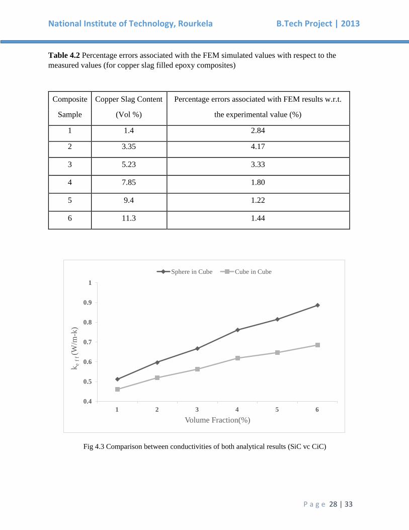
Table 4.2: Percentage errors associated with the FEM simulated values with respect to the
measured values (for copper slag filled epoxy composites)

National Institute of Technology, Rourkela B.Tech Project | 2013
P a g e 2 | 33
Chapter 1
Introduction
National Institute of Technology, Rourkela B.Tech Project | 2013
P a g e 3 | 33
Introduction:
Composite materials are materials that re made from two or more constituent materials with
different physical or chemical properties which when combined, produce a material with
characteristics different from the individual components. The discrete components remain separate
and distinct within the finished structure. One of the materials which is known as the reinforcing
phase, is in the form of fiber sheets or particles and they are embedded in other material which is
called the matrix phase. The prime functions of the matrix are to transfer stresses between the
reinforcing fibers/particles and to protect them from mechanical and/or environmental damage
whereas the presence of fibers/particles in a composite improves its mechanical properties such as
strength, stiffness etc. A composite is therefore a synergistic combination of two or more micro-
constituents that differ in physical form and chemical composition and which are insoluble in each
other. The main objective is to take advantage of the superior properties of both materials without
compromising on the weakness of either. Several light weight and high strength applications have
successfully substituted the traditional materials by composite materials. High toughness, high
strength-to-weight ratio, high creep resistance, and high tensile strength at elevated temperatures
are the reasons why composites are selected for such applications. In a composite, a matrix is
usually a ductile or tough material while the reinforcing materials are strong with low densities. If
the composite is designed and fabricated correctly it combines the strength of the
reinforcement with the toughness of the matrix to achieve a combination of desirable properties
not available in any single conventional material. The strength of the composites depends
primarily on the amount, arrangement and type of fiber and /or particle reinforcement in the
resin. [1]
Types of composites, mainly are divided into:
1. Polymer Matrix Composites
2. Metal Matrix Composites
3. Ceramic Matrix Composited
Other forms include:
1. Carbon Matrix Composites
2. Glass Matrices
3. Elastomers
National Institute of Technology, Rourkela B.Tech Project | 2013
P a g e 4 | 33
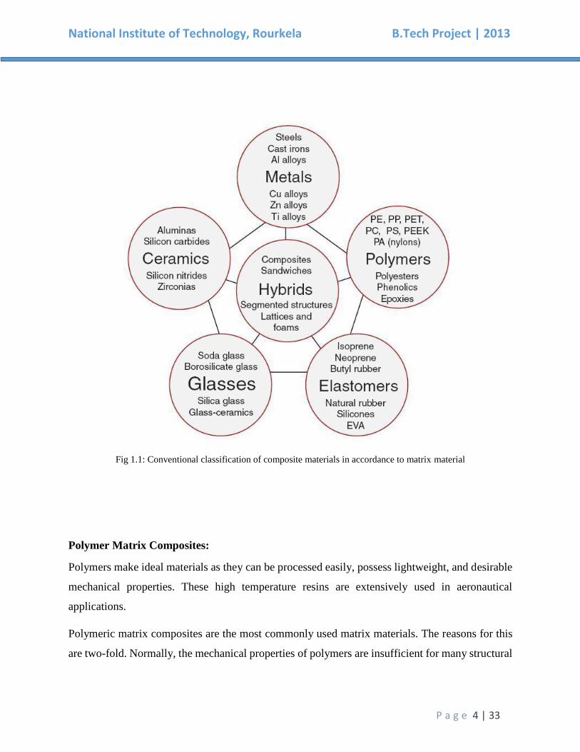
Fig 1.1: Conventional classification of composite materials in accordance to matrix material
Polymer Matrix Composites:
Polymers make ideal materials as they can be processed easily, possess lightweight, and desirable
mechanical properties. These high temperature resins are extensively used in aeronautical
applications.
Polymeric matrix composites are the most commonly used matrix materials. The reasons for this
are two-fold. Normally, the mechanical properties of polymers are insufficient for many structural
National Institute of Technology, Rourkela B.Tech Project | 2013
P a g e 5 | 33
purposes. In particular their strength and stiffness are low compared to metals and ceramics. By
reinforcing other materials with polymers these difficulties can be overcome.
Secondly high pressure and high temperature are not required in the processing of polymer matrix
composites. Also simpler equipment is required for manufacturing polymer matrix composites.
For this reason polymer composites developed rapidly and became popular for structural
applications within no time. Since, overall properties of the composites are superior to those of the
individual polymers, they find their uses in various places. They have a greater elastic modulus
than the neat polymer but are not as brittle as ceramics.
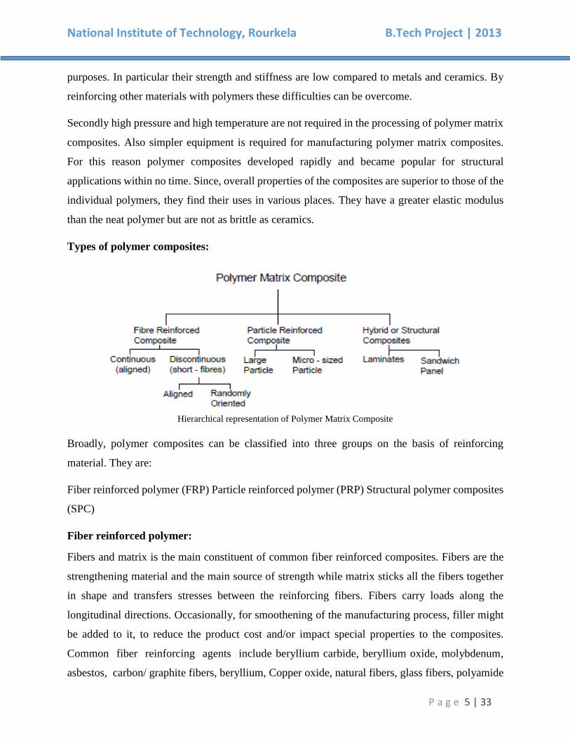
Types of polymer composites:
Hierarchical representation of Polymer Matrix Composite
Broadly, polymer composites can be classified into three groups on the basis of reinforcing
material. They are:
Fiber reinforced polymer (FRP) Particle reinforced polymer (PRP) Structural polymer composites
(SPC)
Fiber reinforced polymer:
Fibers and matrix is the main constituent of common fiber reinforced composites. Fibers are the
strengthening material and the main source of strength while matrix sticks all the fibers together
in shape and transfers stresses between the reinforcing fibers. Fibers carry loads along the
longitudinal directions. Occasionally, for smoothening of the manufacturing process, filler might
be added to it, to reduce the product cost and/or impact special properties to the composites.
Common fiber reinforcing agents include beryllium carbide, beryllium oxide, molybdenum,
asbestos, carbon/ graphite fibers, beryllium, Copper oxide, natural fibers, glass fibers, polyamide
National Institute of Technology, Rourkela B.Tech Project | 2013
P a g e 6 | 33
etc. Similarly epoxy, phenolic resin, polyester, polyurethane, vinyl ester etc. are the common
matrix materials. Polyester is most widely used among these resin materials,. Epoxy, which has
higher adhesion and less shrinkage than polyesters, comes in second for its high cost.
Particle reinforced polymer:
Ceramics and glasses such as small mineral particles, metal particles such as Copper and
amorphous materials, including polymers and carbon black Particles used for reinforcing.
Particles are used for increasing the modulus and to decreasing the ductility of the matrix. Particles
are also used for reducing the cost of the composites. Matrices and reinforcements can be common,
inexpensive materials and are easily handled. High strength, stiffness, high melting temp., low
density, corrosion resistance, and wear resistance are some of the useful properties of ceramics
and glasses. Many ceramics are good thermal and electrical insulators. Some ceramics have special
properties, some are piezoelectric materials, some ceramics are magnetic materials, and a few
special ceramics are also superconductors at very low temperatures. However, glass and ceramics
have one major drawback: they are brittle. An example of particle – reinforced composites is an
automobile tire, which has carbon black particles in a matrix of poly-isobutylene elastomeric
polymer.
Structural Polymer Composites:
These are laminar composites composed of layers of materials held together by matrix. Sandwich
structures also fall under this category. Over the past few decades, it has been found that polymers
have replaced many of the conventional metals/materials in various applications. Because of the
advantages polymers offer over conventional materials, this has been possible. The ease of
processing, productivity and cost reduction are the most important advantages of using polymers.
They have generated wide interest in various engineering fields, particularly in aerospace
applications. New researches are underway worldwide to develop newer composites with varied
combinations of fillers and fibers so that they can be usable under all operational conditions. In
most of these applications, the properties of polymers are modified using fillers and fibers to suit
the high strength/high modulus requirements. Fiber-reinforced polymers offer advantages over
National Institute of Technology, Rourkela B.Tech Project | 2013
P a g e 7 | 33
other conventional materials when specific properties are compared. That’s the reason for these
composites finding applications in diverse fields from appliances to spacecraft’s.
A lot of work has been carried out on various aspects of polymer composites, but a not so many
researchers have reported on the thermal conductivity modification of particulate filled polymers.
In view of this, the present work is undertaken to estimate and measure the effective thermal
conductivity of epoxy filled with metal powders.
2. Metal Matrix Composites:
Metal Matrix Composites have several advantages over monolithic metals, such as higher specific
modulus, higher specific strength, better properties at elevated temperatures and lower
coefficient of thermal expansion. These characteristics of metal matrix composites have led to
consideration for various applications viz. combustion chamber nozzle (in rocket, space shuttle),
housings, tubing, cables, heat exchangers, structural members etc.
3. Ceramic matrix Composites:
One of the main objectives in producing ceramic matrix composites is to increase the toughness.
Naturally it is hoped and indeed often found that there is a concomitant improvement in strength
and stiffness of ceramic matrix composites. High compressive strength, good corrosion resistance,
stability at elevated temperatures and high melting points render ceramic matrix composites, a
preferred method for applications requiring a structural material that can withstand temperatures
above 1500ºC. Naturally, ceramic matrices are the obvious choice for high temperature
applications.
4. Carbon Matrices
Carbon and graphite have a special place in composite materials options, both being highly
superior, high temperature materials with strengths and rigidity that are not affected by temperature
up to 2300ºC. This carbon-carbon composite is fabricated through compaction of carbon or
multiple impregnations of porous frames with liquid carbonizer precursors and subsequent
pyrolization. They can also be manufactured through chemical vapour deposition of pyrolytic
carbon.
National Institute of Technology, Rourkela B.Tech Project | 2013
P a g e 8 | 33
About Copper slag:
Copper slag is produced during pyro-metallurgical production of copper from copper ores contains
materials like iron, alumina, calcium oxide, silica etc. For every ton of metal production about 2.2
ton of slag is generated. Dumping or disposal of such huge quantities of slag cause environmental
and space problems. During the past two decades attempts have been made by several investigators
and copper producing units all over the world to explore the possible utilization of copper slag.
The favorable physico-mechanical characteristics of copper slag can be utilized to make the
products like cement, fill, ballast, abrasive, aggregate, roofing granules, glass, tiles etc. apart from
recovering the valuable metals by various extractive metallurgical routes. [2]
Favorable physico-mechanical and chemical characteristics of copper slag lead to its utilization to
prepare various value added products such as cement, fill, ballast, abrasive, cutting tools,
aggregate, roofing granules, glass, tiles etc. These materials have been found to be possessing
superior mechanical properties and they may be of cheaper varieties than the similar conventional
materials. The utilization of copper slag in such manners may reduce the cost of disposal. This
may also leads to less environmental problems. Improvement in plant economics may also be
expected. Metals and alloys can also be produced from the copper slag by various pyro, hydro and
pyro-hydrometallurgical routes. Therefore, it is evident that judicial utilization of different types
of copper slag is of prime importance in the present days. [2]

National Institute of Technology, Rourkela B.Tech Project | 2013
P a g e 9 | 33
Chapter 2
Literature Review
National Institute of Technology, Rourkela B.Tech Project | 2013
P a g e 10 | 33
LITERATURE REVIEW
This literature review serves as a medium to provide a background information on the issues to be
dealt in this thesis and to articulate the relevance of the present study. This review encircles some
of the related aspects of polymer composites with special reference to their thermal conductivity
characteristics.
From the beginning of the era of industries, slags that are left over when metals are pyro-
metallurgically extracted from ores, have been considered waste. One of them is copper slag which
is produced during the matte smelting and steps of pyro-metallurgical production of copper. In the
process of matte smelting, two phases of liquid: copper-rich matte (sulphides) and slag (oxides)
are formed. Slags containing <0.8% copper are either discarded as waste or sold as products with
properties similar to those of natural basalt (crystalline) or obsidian (amorphous). Utilization and
recovery of these metal depends on the types of slag. Current methods of management of this slag
are recovering of metal, recycling, production of value added products and disposal in stockpiles
or slag dumps. Processed air-cooled and granulated copper slag have number of favorable
mechanical properties for collective use, including excellent soundness characteristics, good
abrasion resistance and good stability.[2]
A lot of work is being done in this area to maximize the output by using slags as composites in
materials such as concrete. For this, knowing the physical and chemical properties of these slags
is very important. One such property is its thermal conductivity.
F C Chen, C L Choy and K Young calculated the thermal conductivity of composite materials
containing thinly dispersed spheroidal inclusions by solving the associated problem of heat flow
across one such inclusion embedded in an infinite matrix in the presence of thermal boundary
resistance. The theory showed good agreement with experimental data for different composites
containing inclusions of various substances, geometry and size, at temperatures from 2K to 300K.
By considering the thermal boundary resistance in a treatment closely paralleling that of Meredith
and Tobias , they also extended the calculation to composites with densely packed spherical
inclusions, which was yet again found to be in close agreement with experiment.[3]
Hansen and Ho [4], Peng et. al [5], Tavman [6] and others have also contributed in this subject of
finding and studying the characteristics of composites.
National Institute of Technology, Rourkela B.Tech Project | 2013
P a g e 11 | 33
While copper slag is generated of the granulated slag of copper refineries, red mud is the solid
waste product of the Bayer process, the means to refine bauxite in generating alumina. These
smelting processes produce large volume of non-metallic dust and soot with red mud bearing the
ability to be a major environmental hazard among the three varieties of slags. However waste
elimination techniques have been the savior to an extent as evident from the various solid waste
reusable applications. Red mud for instance has been used in aluminium metal matrix composites
for wear resistance applications, along with studies of tribological properties [7, 8] that have
successfully cut part of the wastage. Red mud composite coatings [9] have improved wear
resistance. Similarly synergistic effect of copper slag and red mud happen to improve physical and
mechanical properties of bamboo fiber reinforced composites [10]. Again Biswas and Satpathy
[11] justified the possible utilization of copper slag as filler material for the preparation of
composite materials and value added products such as abrasive and cutting tools and railroad
ballast. Also as copper slag is highly stable and non-leachable, it is boasted of as an alternative
material for concrete applications which is evident from Sterlite Industries India’s recent stake in
waste management. Various copper matrix composite materials strengthened with alumina
particulates are engineered by means of pressure molding and sintering. The compactness of
composites increased with the sintering temperature and increase in pressure, and decreased with
the alumina content increasing. The hardness of composite materials increased with the increase
of sintering temperature, pressure and alumina particulates [12]. Among all slags discussed in this
paper, blast furnace (BF) slag is quite the most consumed solid waste which is apparent from its
numerous numbers of usages. Jian Zhou, Shunzhi Qian et al [13] studied cementitious composites
from blast furnace slag and limestone powder which have high compressive strength and improved
tensile strain capacity. For usage in construction purposes, Cheng and Chiu [14] researched the
usage of granulated BF slag as a filler material in making of geo-polymers. Of diversified research
work, remediation of chromium contaminated soils studied by O.A.B Hassan [15] claims of
stabilizing chromium contaminated soils by presence of iron slag in the resulting leachate. In the
present work focus has been in studying the ability of BF slag as a filler material. As this is a
relatively new area of study, groundbreaking work by Padhi and Satpathy [17] and again Padhi
et.al. [16] has emphasized on the erosion study of epoxy resins and hybrid epoxy composites
respectively filled with blast furnace slag.

National Institute of Technology, Rourkela B.Tech Project | 2013
P a g e 12 | 33
Chapter 3
Materials & Methods
National Institute of Technology, Rourkela B.Tech Project | 2013
P a g e 13 | 33
MATERIALS AND METHODS:
This chapter describes the materials and methods used for processing of the selected composites
under this research. It presents the details of the characterization and thermal conductivity tests
which the composite samples are subjected to. The numerical methodology related to the
determination of thermal conductivity based on finite element method is also presented in this
chapter of the thesis.
MATERIALS
Matrix Material:
Epoxy LY 556 resin, chemically belonging to the “epoxide‟ family is used as the matrix material.
Common name of this resin is Bisphenol-A-Diglycidyl-Ether. The low temperature curing epoxy
resin (Araldite LY 556) and the corresponding hardener (HY 951) are mixed in a ratio of 10:1 by
weight as recommended. Both, the hardener and the epoxy resin are supplied by Ciba Geigy India
Ltd. Epoxy is chosen primarily because it is the most commonly used polymer and because of its
insulating behavior (a low value of thermal conductivity, which is about 0.363 W/m-K).
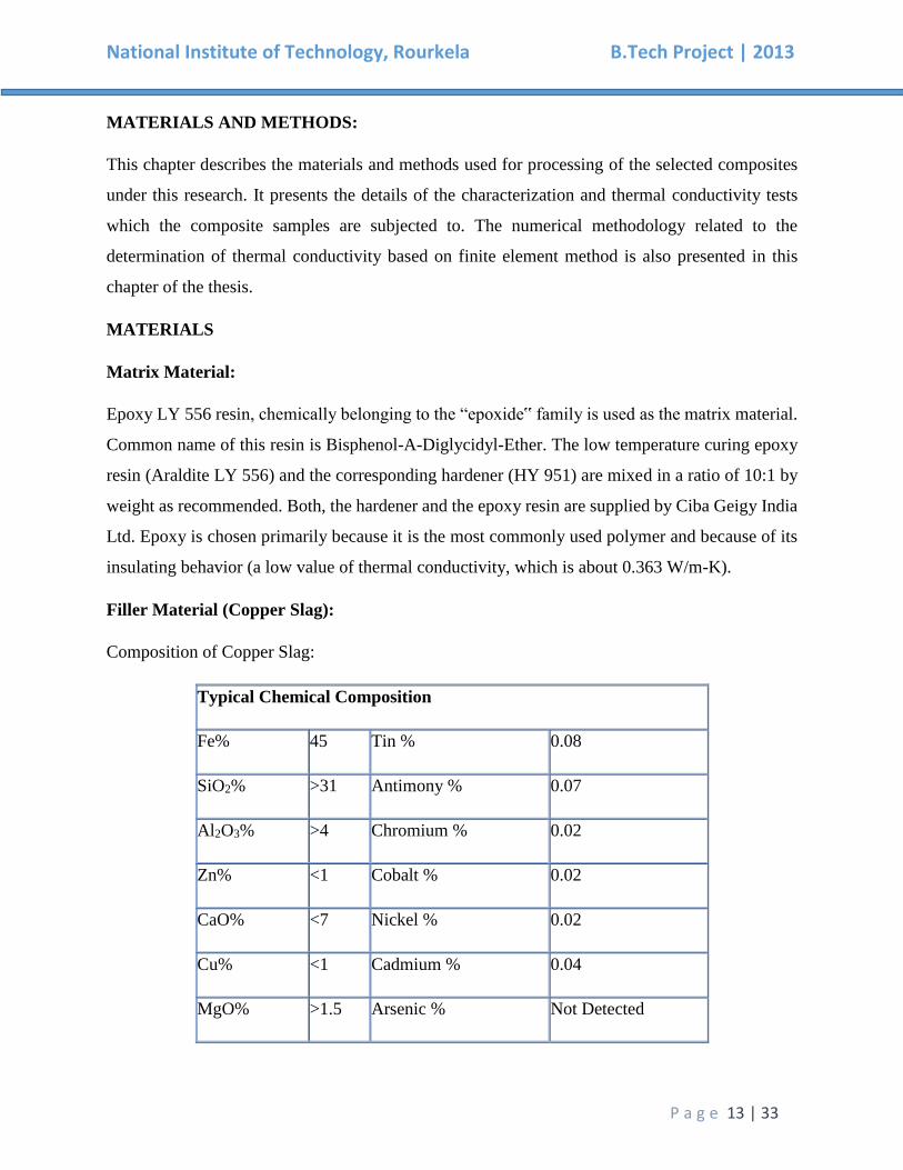
Filler Material (Copper Slag):
Composition of Copper Slag:
Typical Chemical Composition
Fe% 45 Tin % 0.08
SiO2% >31 Antimony % 0.07
Al2O3% >4 Chromium % 0.02
Zn% <1 Cobalt % 0.02
CaO% <7 Nickel % 0.02
Cu% <1 Cadmium % 0.04
MgO% >1.5 Arsenic % Not Detected
National Institute of Technology, Rourkela B.Tech Project | 2013
P a g e 14 | 33
TiO2% <2 Beryllium % Not Detected
Free Silica <1 Trace elements % <0.5
Lead% 0.1 Moisture % <1
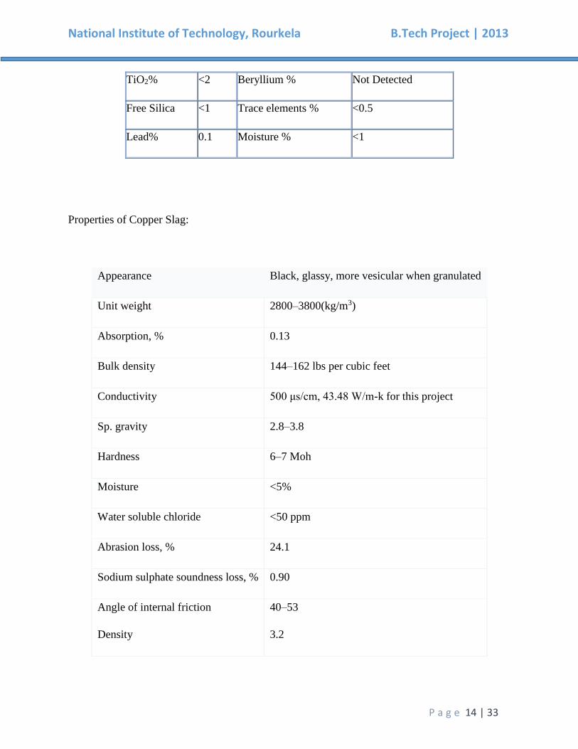
Properties of Copper Slag:
Appearance Black, glassy, more vesicular when granulated
Unit weight 2800–3800(kg/m3)
Absorption, % 0.13
Bulk density 144–162 lbs per cubic feet
Conductivity 500 μs/cm, 43.48 W/m-k for this project
Sp. gravity 2.8–3.8
Hardness 6–7 Moh
Moisture <5%
Water soluble chloride <50 ppm
Abrasion loss, % 24.1
Sodium sulphate soundness loss, % 0.90
Angle of internal friction
Density
40–53
3.2
National Institute of Technology, Rourkela B.Tech Project | 2013
P a g e 15 | 33
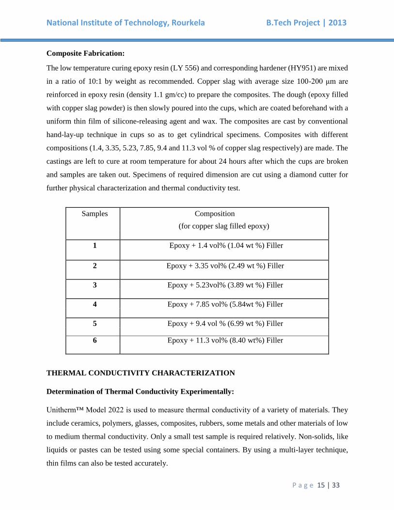
Composite Fabrication:
The low temperature curing epoxy resin (LY 556) and corresponding hardener (HY951) are mixed
in a ratio of 10:1 by weight as recommended. Copper slag with average size 100-200 μm are
reinforced in epoxy resin (density 1.1 gm/cc) to prepare the composites. The dough (epoxy filled
with copper slag powder) is then slowly poured into the cups, which are coated beforehand with a
uniform thin film of silicone-releasing agent and wax. The composites are cast by conventional
hand-lay-up technique in cups so as to get cylindrical specimens. Composites with different
compositions (1.4, 3.35, 5.23, 7.85, 9.4 and 11.3 vol % of copper slag respectively) are made. The
castings are left to cure at room temperature for about 24 hours after which the cups are broken
and samples are taken out. Specimens of required dimension are cut using a diamond cutter for
further physical characterization and thermal conductivity test.
THERMAL CONDUCTIVITY CHARACTERIZATION
Determination of Thermal Conductivity Experimentally:
Unitherm™ Model 2022 is used to measure thermal conductivity of a variety of materials. They
include ceramics, polymers, glasses, composites, rubbers, some metals and other materials of low
to medium thermal conductivity. Only a small test sample is required relatively. Non-solids, like
liquids or pastes can be tested using some special containers. By using a multi-layer technique,
thin films can also be tested accurately.
Samples Composition
(for copper slag filled epoxy)
1 Epoxy + 1.4 vol% (1.04 wt %) Filler
2 Epoxy + 3.35 vol% (2.49 wt %) Filler
3 Epoxy + 5.23vol% (3.89 wt %) Filler
4 Epoxy + 7.85 vol% (5.84wt %) Filler
5 Epoxy + 9.4 vol % (6.99 wt %) Filler 6 Epoxy + 11.3 vol% (8.40 wt%) Filler
National Institute of Technology, Rourkela B.Tech Project | 2013
P a g e 16 | 33
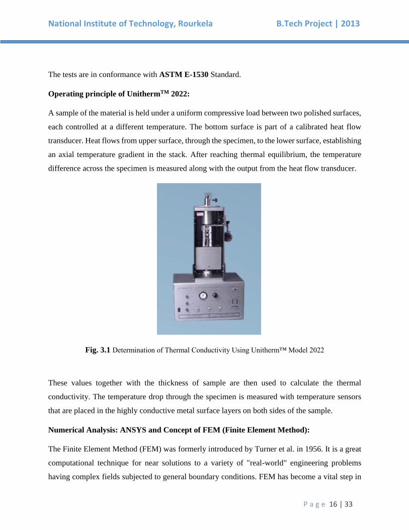
The tests are in conformance with ASTM E-1530 Standard.
Operating principle of UnithermTM 2022:
A sample of the material is held under a uniform compressive load between two polished surfaces,
each controlled at a different temperature. The bottom surface is part of a calibrated heat flow
transducer. Heat flows from upper surface, through the specimen, to the lower surface, establishing
an axial temperature gradient in the stack. After reaching thermal equilibrium, the temperature
difference across the specimen is measured along with the output from the heat flow transducer.
Fig. 3.1 Determination of Thermal Conductivity Using Unitherm™ Model 2022
These values together with the thickness of sample are then used to calculate the thermal
conductivity. The temperature drop through the specimen is measured with temperature sensors
that are placed in the highly conductive metal surface layers on both sides of the sample.
Numerical Analysis: ANSYS and Concept of FEM (Finite Element Method):
The Finite Element Method (FEM) was formerly introduced by Turner et al. in 1956. It is a great
computational technique for near solutions to a variety of "real-world" engineering problems
having complex fields subjected to general boundary conditions. FEM has become a vital step in
National Institute of Technology, Rourkela B.Tech Project | 2013
P a g e 17 | 33
the modeling or design of a physical phenomenon in various fields of engineering. A physical
phenomenon usually occurs in a continuum of matter (solid, liquid, or gas) involving some field
variables. They vary from point to point, thus having an infinite number of solutions in the domain.
FEM relies on the fragmentation of the domain into a predetermined number of subdomains or
elements for which the systematic approximate solution is constructed by applying variational or
weighted residual methods. The problem is reduced to that of a finite number of unknowns by
FEM. This is done by dividing the domain into elements and by articulating the unknown field
variable in terms of the assumed approximating functions within each element. These functions
(which are also known as interpolation functions) are defined in terms of the values of the field
variables at specific points, referred to as nodes. Nodes are usually located along the element
boundaries and they connect adjacent elements. Its ability to discretize the irregular domains
with finite elements makes this method a valuable and practical analysis tool for the solution of
boundary, initial and Eigen value problems arising in various engineering disciplines.
Hence, FEM is a numerical procedure that can be used to obtain solutions to a large class of
engineering fields involving heat transfer, fluid flow, stress analysis, etc. ANSYS is a general
purpose finite element modeling software for numerically solving a wide range of mechanical
problems such as structural analysis (both linear and nonlinear), heat transfer, static/dynamic and
fluid problems. Acoustic and electromagnetic problems can also be solved using ANSYS.
Basic Steps in FEM:
The finite element method involves:
The governing differential equation of the problem is converted into an integral form at first. There
are two techniques to accomplish this:
(i) Variational Technique
(ii) Weighted Residual Technique.
In variational technique, the calculus of variation is used to obtain the integral form
corresponding to the given differential equation. This integral needs to be minimalized to
obtain the solution. For structural mechanics problems, the integral form turns out to be the
expression for the total potential energy of the structure.
National Institute of Technology, Rourkela B.Tech Project | 2013
P a g e 18 | 33
In weighted residual technique, the integral form is made as a weighted integral of the governing
differential equation where the weight functions are known and arbitrary, except that they satisfy
certain boundary conditions. To reduce the continuity, this integral form is often modified using
the divergence theorem. This integral form is set to zero to obtain the solution. For structural
mechanics problems, if the weight function is considered as the virtual displacement, then the
integral form becomes the expression of the virtual work of the structure.
The second step involves dividing the domain of the problem into a number of parts, called as
elements. For one-dimensional or 1-D problems, these elements are nothing but line segments
having only length but no shape. For problems of higher dimensions, the elements have both size
and shape. For two-dimensional (2D) or axi-symmetric problems, the elements used are triangles,
rectangles etc. having straight or curved boundaries. Curved sided element is a better choice when
the domain boundary is curved. For three-dimensional or 3D problems, the shapes used are
tetrahedron and parallelepiped (prism whose faces are all parallelograms) having straight or curved
surfaces.
The division of the domain into elements is called a mesh. In this step, a suitable estimate is chosen
for the primary variable of the problem, over a typical element, using interpolation functions (also
called shape functions) and the unknown values of the primary variable at some pre-selected points
of the element, called as nodes. Usually polynomials are chosen as the shape functions. For 1-D
elements, there are at least 2 nodes placed at the endpoints. Additional nodes are placed in the
interior of the element. Whereas in the case of 2-D and 3-D elements, the nodes are placed at the
vertices (atleast 3 nodes for triangles, and atleast 4 nodes for rectangles, quadrilaterals as well as
tetrahedral and a minimum of 8 nodes for parallelepiped shaped elements). Further, additional
nodes are placed either on the boundaries or in the interior. The values of the primary variable at
the nodes are called as the degrees of freedom.
To get the exact solution, the expression for the primary variable must contain a complete set of
polynomials (i.e., infinite terms) or if it contains only finite number of terms, then the number of
elements has to be infinite. In either case, it results into an infinite set of algebraic equations. To
make the problem amenable, only a finite number of elements and an expression with only finite
number of terms are used. Hence, we get only an approximate solution. (Therefore, the expression
for the primary variable chosen to obtain an approximate solution is called an approximation).
National Institute of Technology, Rourkela B.Tech Project | 2013
P a g e 19 | 33
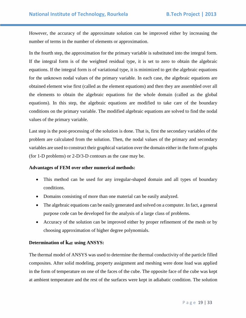
However, the accuracy of the approximate solution can be improved either by increasing the
number of terms in the number of elements or approximation.
In the fourth step, the approximation for the primary variable is substituted into the integral form.
If the integral form is of the weighted residual type, it is set to zero to obtain the algebraic
equations. If the integral form is of variational type, it is minimized to get the algebraic equations
for the unknown nodal values of the primary variable. In each case, the algebraic equations are
obtained element wise first (called as the element equations) and then they are assembled over all
the elements to obtain the algebraic equations for the whole domain (called as the global
equations). In this step, the algebraic equations are modified to take care of the boundary
conditions on the primary variable. The modified algebraic equations are solved to find the nodal
values of the primary variable.
Last step is the post-processing of the solution is done. That is, first the secondary variables of the
problem are calculated from the solution. Then, the nodal values of the primary and secondary
variables are used to construct their graphical variation over the domain either in the form of graphs
(for 1-D problems) or 2-D/3-D contours as the case may be.
Advantages of FEM over other numerical methods:
This method can be used for any irregular-shaped domain and all types of boundary
conditions.
Domains consisting of more than one material can be easily analyzed.
The algebraic equations can be easily generated and solved on a computer. In fact, a general
purpose code can be developed for the analysis of a large class of problems.
Accuracy of the solution can be improved either by proper refinement of the mesh or by
choosing approximation of higher degree polynomials.
Determination of keff using ANSYS:
The thermal model of ANSYS was used to determine the thermal conductivity of the particle filled
composites. After solid modeling, property assignment and meshing were done load was applied
in the form of temperature on one of the faces of the cube. The opposite face of the cube was kept
at ambient temperature and the rest of the surfaces were kept in adiabatic condition. The solution
National Institute of Technology, Rourkela B.Tech Project | 2013
P a g e 20 | 33
to the model along with the post processing results helped us to obtain the effective thermal
conductivity of the composite.
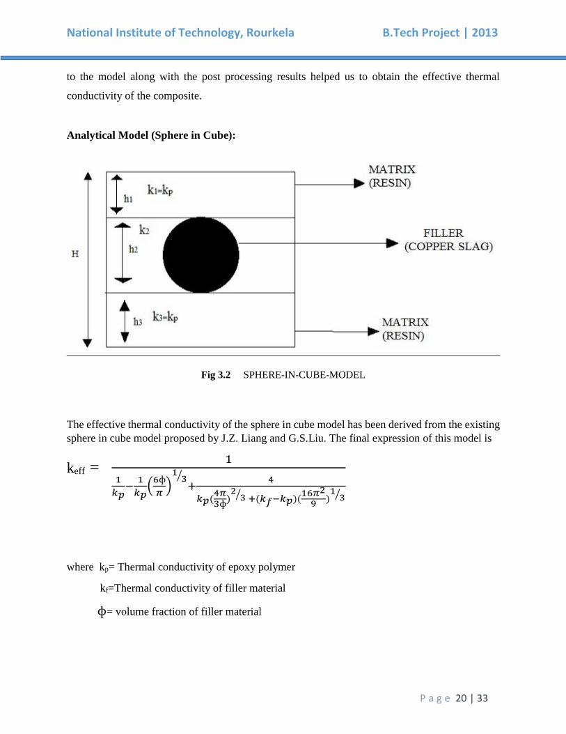
Analytical Model (Sphere in Cube):
Fig 3.2 SPHERE-IN-CUBE-MODEL
The effective thermal conductivity of the sphere in cube model has been derived from the existing
sphere in cube model proposed by J.Z. Liang and G.S.Liu. The final expression of this model is
keff = 1
1
𝑘𝑝−
1
𝑘𝑝(
6ɸ
𝜋)
13⁄
+4
𝑘𝑝(4𝜋3ɸ
)2
3⁄ +(𝑘𝑓−𝑘𝑝)(16𝜋2
9 )1
3⁄
where kp= Thermal conductivity of epoxy polymer
kf=Thermal conductivity of filler material
ɸ= volume fraction of filler material
National Institute of Technology, Rourkela B.Tech Project | 2013
P a g e 21 | 33
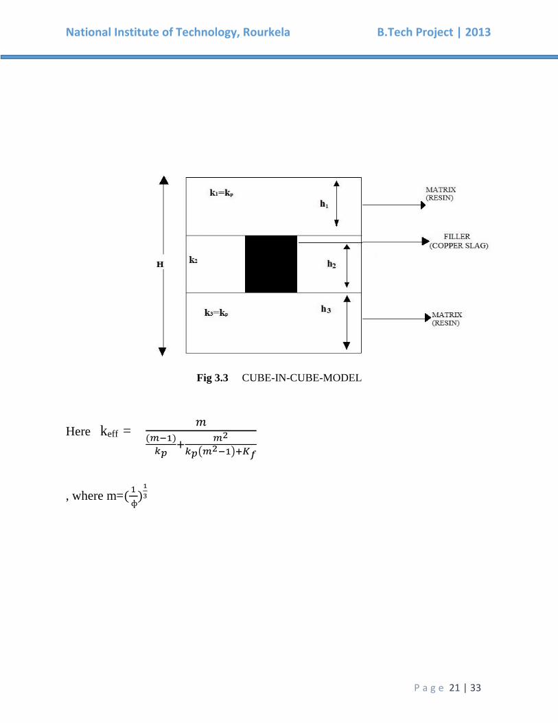
Fig 3.3 CUBE-IN-CUBE-MODEL
Here keff = 𝑚
(𝑚−1)
𝑘𝑝+
𝑚2
𝑘𝑝(𝑚2−1)+𝐾𝑓
, where m=(1
ɸ)
1
3

National Institute of Technology, Rourkela B.Tech Project | 2013
P a g e 22 | 33
Chapter 4
Results & Discussion
National Institute of Technology, Rourkela B.Tech Project | 2013
P a g e 23 | 33
RESULTS AND DISCUSSION
Description of the problem:
For functional design and application of composite materials the most important parameter is the
effective properties of composite. The important factors that regulate the effective properties is the
microstructure of the composite and it can be controlled to an appreciable level. Microstructure of
composite includes the size, shape, spatial distribution and orientation of the reinforcing inclusion
in the matrix. Although most inclusions have random distributions, periodic structure can provide
the details of the effect of microstructure on the effective properties can be. System with periodic
structures is easy to analyze because of the high degree of symmetry.
Thermal analysis is carried out for the conductive heat transfer through the composite body using
the finite-element program ANSYS. For the thermal analysis purpose, three-dimensional physical
models with spheres-in-a-cube and cube in cube lattice array have been used to simulate the
microstructure of composite materials for six different filler concentrations. Further the effective
thermal conductivities of these composites filled with copper slag powder up to about 11.3% by
volume is numerically determined by using ANSYS.
Assumptions:
For the ideal case thermal analysis it will be assumed that:
1. The composites are considered to be macroscopically homogeneous.
2. Both the matrix and filler are homogeneous and isotropic.
3. The thermal contact resistance between the matrix and the filler is assumed to be negligible.
4. Voids are not present in the composite lamina.
5. The problem considered is based on 3D physical model.
6. The filler are arranged in a square periodic array/uniformly distributed in matrix.
National Institute of Technology, Rourkela B.Tech Project | 2013
P a g e 24 | 33
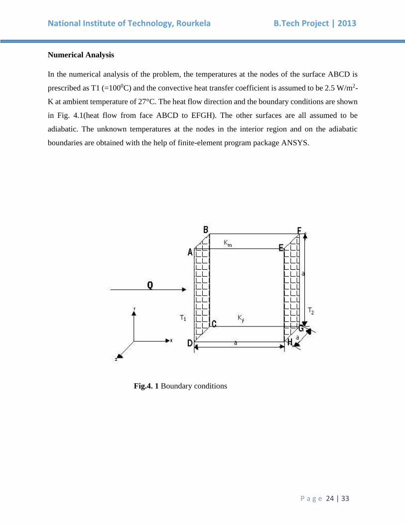
Numerical Analysis
In the numerical analysis of the problem, the temperatures at the nodes of the surface ABCD is
prescribed as T1 (=1000C) and the convective heat transfer coefficient is assumed to be 2.5 W/m2-
K at ambient temperature of 27°C. The heat flow direction and the boundary conditions are shown
in Fig. 4.1(heat flow from face ABCD to EFGH). The other surfaces are all assumed to be
adiabatic. The unknown temperatures at the nodes in the interior region and on the adiabatic
boundaries are obtained with the help of finite-element program package ANSYS.
Fig.4. 1 Boundary conditions
National Institute of Technology, Rourkela B.Tech Project | 2013
P a g e 25 | 33
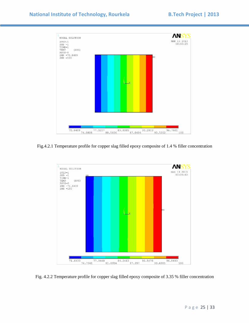
Fig.4.2.1 Temperature profile for copper slag filled epoxy composite of 1.4 % filler concentration
Fig. 4.2.2 Temperature profile for copper slag filled epoxy composite of 3.35 % filler concentration
National Institute of Technology, Rourkela B.Tech Project | 2013
P a g e 26 | 33
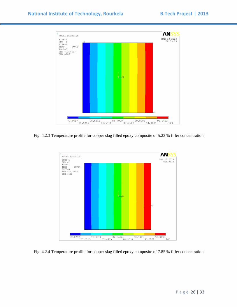
Fig. 4.2.3 Temperature profile for copper slag filled epoxy composite of 5.23 % filler concentration
Fig. 4.2.4 Temperature profile for copper slag filled epoxy composite of 7.85 % filler concentration
National Institute of Technology, Rourkela B.Tech Project | 2013
P a g e 27 | 33
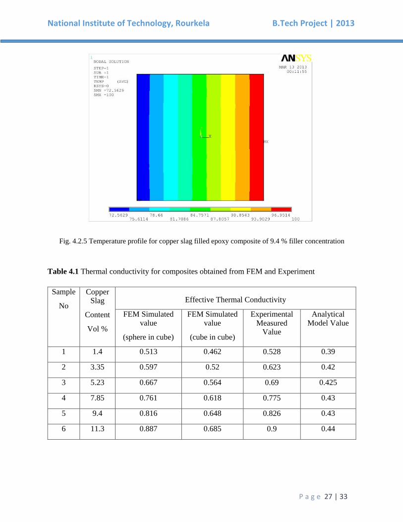
Fig. 4.2.5 Temperature profile for copper slag filled epoxy composite of 9.4 % filler concentration
Table 4.1 Thermal conductivity for composites obtained from FEM and Experiment
Sample
No
Copper Slag
Content
Vol %
Effective Thermal Conductivity
FEM Simulated value
(sphere in cube)
FEM Simulated value
(cube in cube)
Experimental Measured
Value
Analytical Model Value
1 1.4 0.513 0.462 0.528 0.39
2 3.35 0.597 0.52 0.623 0.42
3 5.23 0.667 0.564 0.69 0.425
4 7.85 0.761 0.618 0.775 0.43
5 9.4 0.816 0.648 0.826 0.43
6 11.3 0.887 0.685 0.9 0.44
National Institute of Technology, Rourkela B.Tech Project | 2013
P a g e 28 | 33
Table 4.2 Percentage errors associated with the FEM simulated values with respect to the
measured values (for copper slag filled epoxy composites)
Composite Copper Slag Content Percentage errors associated with FEM results w.r.t.
Sample (Vol %) the experimental value (%)
1 1.4 2.84
2 3.35 4.17
3 5.23 3.33
4 7.85 1.80
5 9.4 1.22
6 11.3 1.44
Fig 4.3 Comparison between conductivities of both analytical results (SiC vc CiC)
0.4
0.5
0.6
0.7
0.8
0.9
1
1 2 3 4 5 6
ke
f f (W
/m-k
)
Volume Fraction(%)
Sphere in Cube Cube in Cube
National Institute of Technology, Rourkela B.Tech Project | 2013
P a g e 29 | 33
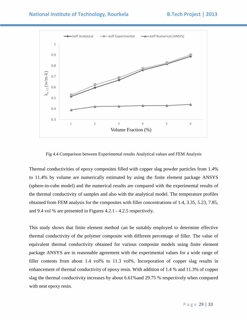
Fig 4.4 Comparison between Experimental results Analytical values and FEM Analysis
Thermal conductivities of epoxy composites filled with copper slag powder particles from 1.4%
to 11.4% by volume are numerically estimated by using the finite element package ANSYS
(sphere-in-cube model) and the numerical results are compared with the experimental results of
the thermal conductivity of samples and also with the analytical model. The temperature profiles
obtained from FEM analysis for the composites with filler concentrations of 1.4, 3.35, 5.23, 7.85,
and 9.4 vol % are presented in Figures 4.2.1 - 4.2.5 respectively.
This study shows that finite element method can be suitably employed to determine effective
thermal conductivity of the polymer composite with different percentage of filler. The value of
equivalent thermal conductivity obtained for various composite models using finite element
package ANSYS are in reasonable agreement with the experimental values for a wide range of
filler contents from about 1.4 vol% to 11.3 vol%. Incorporation of copper slag results in
enhancement of thermal conductivity of epoxy resin. With addition of 1.4 % and 11.3% of copper
slag the thermal conductivity increases by about 6.61%and 29.75 % respectively when compared
with neat epoxy resin.
0.3
0.4
0.5
0.6
0.7
0.8
0.9
1
1 2 3 4 5 6
ke
f f (w
/m-k
)
Volume Fraction (%)
keff Analytical keff Experimental keff Numerical (ANSYS)

National Institute of Technology, Rourkela B.Tech Project | 2013
P a g e 30 | 33
Chapter 5
Conclusions &
Future Scope
National Institute of Technology, Rourkela B.Tech Project | 2013
P a g e 31 | 33
CONCLUSIONS:
Successful fabrication of copper slag powder filled epoxy composites is carried out by
Hand-lay-up technique.
The values of the effective thermal conductivity (keff) obtained for various composite
models from FEM are in reasonable agreement with the experimental values for a wide
range of filler content from 1.4 vol% to 11.3 vol%.
Finite Element Method (FEM) can be suitably employed to determine the effective thermal
conductivity (keff) of these particulate filled polymer composites for different volume
fractions of copper slag.
Inclusion of copper slag results in improvement of thermal conductivity of epoxy resin.
With addition of 11.3 vol. % of copper slag, the thermal conductivity improves by about
31.25 % with respect to neat epoxy resin.
FUTURE SCOPE:
Copper slag is one of the materials that is considered as a waste material that could have a
promising future in construction industry as partial substitute of either cement or aggregates.
Studies are already being carried out to increase the output by using copper slags and other
materials as composites. From this project, it is evident that copper slag can be used to enhance
the characteristics when used with other materials. Hence, it has a huge potential to be used for
industrial applications.
National Institute of Technology, Rourkela B.Tech Project | 2013
P a g e 32 | 33
REFERANCES:
1. Rajlakshmi Nayak, Dr. Alok satapathy (2010). A study on thermal conductivity of particulate
reinforced epoxy composites.
2. Bipra Gorai, R.K. Jana, Premchand, Characteristics and utilisation of copper slag—a review,
Resources, Conservation and Recycling, 2003, 299–313
3. C.L. Choy, and K. Young, Thermal Conductivity of Semicrystalline Polymers– A Model, J.
Polymer, 18(8) (1977) 769–776.
4. D. Hansen and C. Ho, Thermal Conductivity of High Polymers, J. of Poly. Sci. Part A, 3(2)
(1965) 659–670.
5. S. Peng and R. Landel, Induced Anisotropy of Thermal Conductivity of Polymer Solids under
Large Strains, J. Appl. Poly. Sci., 19(1) (1975) 49–68.
6. I. Tavman, Thermal Anisotropy of Polymers as a Function of their Molecular Orientation,
Experimental Heat Transfer, Fluid Mechanics, and Thermodynamics, Elsevier (1991) 1562–1568,
7. Prasad Naresh & Acharya S.K; “Development of Metal Matrix Composite Using Red mud an
Industrial Waste for Wear Resistant Applications.” Proceedings of the International Conference
on Industrial Tribology, Mumbai, Dec.15-18, 2004, pp.164-170
8. Prasad Naresh & Acharya S.K; “Tribological Behaviour of Aluminium Red Mud Composite.”
Presented at the 12th International Conference on Solid Waste Technology and Management,
Philadelphia, USA, April 3-6, 2005.
9. Sutar, H., Mishra, S. , Sahoo, S. , Satapathy, A. and Kumar, V. (2012) Morphology and solid
particle erosion wear behavior of red mud composite coatings. Natural Science, 4, 832-838. doi:
10.4236/ns.2012.411111.
10. Sandhyarani Biswas, Amar Patnaik, and Ritesh Kaundal, “Effect of Red Mud and Copper Slag
Particles on Physical and Mechanical Properties of Bamboo-Fiber-Reinforced Epoxy
Composites,” Advances in Mechanical Engineering, vol. 2012, Article ID 141248, 6 pages, 2012.
doi:10.1155/2012/141248
11. Biswas S, Satapathy A “Use of copper slag in glass-epoxy composites for improved wear
resistance”. Waste Manag Res. 2010 Jul;28(7):615-25. doi: 10.1177/0734242X09352260. Epub
2009 Nov 26.
12. Wei Ping Liu, 2011, “Use Copper Slag to Prepare Copper Matrix Composites” Advanced
Materials Research, 183-185, 1586.
13. Jian Zhou, Shunzhi Qian, M. Guadalupe Sierra Beltran, Guang Ye, Klaas van Breugel, Victor
C. Li “Development of engineered cementitious composites with limestone powder and blast
furnace slag”. Materials and Structures, Springer Link July 2010, Volume 43, Issue 6, pp 803-
814.
14. T W Cheng, J P Chiu “Fire-resistant geo polymer produced by granulated blast furnace slag”.
National Institute of Technology, Rourkela B.Tech Project | 2013
P a g e 33 | 33
Minerals Engineering 16 (2003) 205–210, Pergamon.
15. O A B Hassan, “Remediation of Chromium contaminated soil using blast furnace slag”. Int. J.
Sus. Dev. Plann. Vol. 6, No. 1 (2011) 81–90.
16. Prasanta Kumar Padhi, Alok Satpathy, “Parametric Evaluation of Erosion Response of Epoxy
Resin filled with blast furnace slag using Taguchi technique”. International Conference on
"Advancements in Polymeric Materials", APM 2012, February 10 -12, 2012, CIPET Ahmedabad.
17. Prasanta Kumar Padhi, Alok Satpathy, Srimant Kumar Mishra, Sisir Mantry, “Erosive wear
behavior of Glass-Epoxy hybrid composites reinforced with blast furnace slag”. International
Conference on "Advancements in Polymeric Materials", APM 2012, February 10 -12, 2012,
CIPET Ahmedabad.
OTHER REFERANCES:
I. Google
II. Wikipedia
III. How Stuff Works