b-pfs-b-ps-b-pfs-b-pmma pentablock...
TRANSCRIPT

Synthesis and Self-Assembly of Organometallic
Semiconducting PMMA-b-PFS-b-PS-b-PFS-b-PMMA
Pentablock Copolymers
Dem Fachbereich Chemie
der Technische Universität Darmstadt
zur Erlangung des akademischen Grades eines
Doctor rerum naturalium (Dr. rer. nat.)
genehmigte
DISSERTATION
eingereicht von
M. Tech. Chem. Uttam Datta
aus New Delhi (India)
Berichterstatter: Prof. Dr. M. Rehahn
Mitberichterstatter: Prof. Dr. E. Gruber
Tag der Einreichung: Mai 9, 2005
Tag der Mündlichen Prüfung: Juni 27, 2005
Darmstadt 2005
D17

In the loving memory of my papa

ACKNOWLEDGEMENT
As I sit here in front of my ThinkPad I realize that writing an acknowledgement is
perhaps the most difficult part of a Ph.D. dissertation. How can you mention all of the
people you have interacted with in a page or two? Therefore, the first thing I would like
to say is THANK YOU to all the people with whom I have worked with over the past
three years.
First and foremost I would like to express my deepest gratitude to my supervisor
Prof. Dr. Matthias Rehahn (Dekanat, Fachbereich Chemie, TUD) whose sincere and
invaluable guidance helped me in bringing this thesis work to a successful completion.
Thanks for all the discussions and the ideas.
This work could not have been carried out without the help and support of Dr.
Christian Kloninger (presently scientist in 3M, Neuse) who introduced me to the concept
of anionic polymerization and got me started in the lab with the high vacuum line and the
schlenk techniques. My sincere thanks to Dr. Roland Klein for the SAXS measurements
at DESY and frequent little snags regarding the local area network, computers, printers
etc.
I also thank my colleagues including Michael Roth, Stefan Tockner and Dr.
Bellas for making the work atmosphere lively.
My heartfelt warm thanks to Frau Cornelia Gräfing (Conny) for everyday trouble
shooting small and big problems associated with the formalities of TUD and my stay as a
foreigner in Darmstadt.
My special thanks to Dr. Jianjan Xu for all the efforts with regard to the DRS
conductivity measurements. I would also like to acknowledge the discussions with Prof.
Dr. Volker Abetz regarding microphase separation and SAXS data interpretation. Thanks
to Herr Christoph Brinkmann for the GPC analyses, Dr. Tilmann Ruhl for training me on
TEM and Dr. Birgit Staben for TGA/DSC measurements.
At this moment I wish to acknowledge the blessings and good wishes of my
family members. A special thanks to papa’s grandson ‘Hercules’. Last but not the least, I
have no words to acknowledge the contribution of my better half Dr. Anupama Datta
whose constant emotional support and encouragement made all the difference and
without whom I am sure I would not have made it.

Diese Arbeit wurde am Ernst-Berl-Institut für Technische und Makromolekulare
Chemie der Technische Universität Darmstadt und am Deutschen Kunststoff Institut
Darmstadt, unter der Leitung von Prof. Dr. M. Rehahn in der Zeit von Juni 2002 bis Juni
2005 durchgeführt.

TABLE OF CONTENTS
Contents Page No.
Chapter 1 Introduction
1 Block Copolymers 1
1.1 Types of Block Copolymers 1
1.2 General Methods for Synthesis of Block Copolymers 2
1.2.1 Cationic Polymerization 2
1.2.2 Living Free Radical Polymerization 3
1.2.3 Group Transfer Polymerization 3
1.2.4 Ring Opening Metathesis Polymerization 4
1.2.5 Living Anionic Polymerization 4
1.2.5a Experimental Criteria for Living Anionic Polymerization 4
1.2.5b Suitable Monomers 5
1.2.5c Initiators 5
1.2.5d Kinetics and Mechanism of Living Anionic Polymerization 6
1.3 Anionic Polymerization of Styrene 9
1.4 Anionic Polymerization of Methyl Methacrylate 11
1.5 Ferrocene Containing Polymers 14
1.5.1 Polymers Containing Ferrocene in the Main Chain 14
1.5.2 Polymers Containing Ferrocene as Side Chains 17
1.5.3 Polyferrocenylsilanes 18
1.5.4 Pentablock Copolymers containing PFS, PS and PMMA
Segments
21
1.6 Self-Assembly by Means of Microphase Separation in Block
Copolymers
23
1.6.1 Phase Transitions in Block Copolymer Melts 23
1.6.2 Flory-Huggins Theory 24
1.6.3 Strong Segregation Limit Theory 27
1.6.4 Weak Segregation Limit Theory 28
1.6.5 Self-Consistent Field Theory (SCFT) 29
1.6.6 Integral Equation Theories 30
1.6.7 Nanoscale Morphologies generated by Self-Assembly of
Diblock Copolymers
31
1.6.8 Complex Phases in Block Copolymers 31
1.6.9 Microphase Separation in Multiblock Copolymers 33
1.6.10 Microphase Separation and Nanolithography 35
1.7 Conducting Polymers 36
1.7.1 Band Theory of Conductivity 38
1.8 Scope/Motivation of the Work 39
1.9 Strategy 39
Chapter 2 Synthesis and Polymerization of [1]Dimethylsilaferrocenophane
2.1
Synthesis of Monomer (FS) 40
2.2 Purification of Monomer (FS) 41
2.3 Living Anionic Polymerization of
[1]Dimethylsilaferrocenophane
44
2.3.1 Anionic Ring Opening Polymerization Initiated by n-BuLi 44
2.3.2 Influence of Impurities on FS Polymerization 45
2.3.3 Investigation of the ‘Living Character’ of Polymerization 45
Chapter 3 Synthesis and Characterization of PMMA-b-PFS-b-PS-b-PFS-b-PMMA
Pentablock Copolymers
3.1 Difunctional Initiator ‘Lithium Naphthalide’ 49
3.1.1 Radical Anion 49
3.1.2 Analysis of the Initiator Solution 49
3.2 DMSB as “Carbanion Pump” for Efficient End-
Capping/Trapping of Living PFS Chain Ends during MMA
Polymerization
50
3.3 Pentablock Copolymer Synthesis 51
3.4 Purification of Pentablock Copolymers by Means of Selective
Precipitation
55
3.5 Molecular Characterization of the Pentablock Copolymers 56

Chapter 4 Self-Assembly of PMMA-b-PFS-b-PS-b-PFS-b-PMMA Pentablock
Copolymers
4.1 Determination of Solubility Parameters 60
4.2 Thermal Characterization of the Pentablock Copolymer
63
4.2.1 Thermogravimetry and Thermal Stability 63
4.2.2 Differential Calorimetry 64
4.3 Phase Behavior of the Pentablock Copolymers 66
4.4 Phase Behavior of the Pentablock Copolymer Blends with PS,
PFS and PMMA Homopolymers
80
4.5 Conclusion 85
Chapter 5 Semiconducting Properties of Block Copolymers from PFS, PS and PMMA
Segments
5.1 Principle of Dielectric Relaxation Spectroscopy (DRS) 86
5.1.1 Measurement Principle
86
5.1.2 Measurement Techniques 87
5.1.3 Polarization Mechanisms 87
5.2 Doping of Homo and Block Copolymers 88
5.3 Mechanism of Conductivity in PFS containing Polymers 89
5.4 Conductivity Measurements by DRS 89
5.4.1 DRS Measurements of 24000PFS100 91
5.4.2 DRS Measurements of Diblock Copolymer AB Type, 35000
PFS102-b-PMMA103
92
5.4.3 DRS Measurements of Triblock Copolymer BAB Type, 35000
PFS50-b-PS101-b-PFS52
93
5.4.4 DRS Measurements of Triblock Copolymer ABC Type, 45000
PS103-b-PFS101-b-PMMA99
94
5.4.5 DRS Measurements of Pentablock Copolymer CBABC Type, 45000
PMMA51-b-PFS48-b-PS99-b-PFS53-b-PMMA49
95
5.5 Conclusion 97

Chapter 6 Abstract and Zusammenfassung
6.1 Abstract 98
6.2 Zusammenfassung
100
Chapter 7 Experimental
7.1 Reagents and Chemicals 102
7.1.1 Solvents 102
7.1.2 Monomers, Initiators and other Reagents 103
7.2 Synthesis of [1]Dimethylsilaferrocenophane (FS) 105
7.3 Polymerization 106
7.4 Film Preparation for TEM and SAXS 111
7.5 Instrumentation 112
7.6 Dielectric Relaxation Spectroscopy (DRS) and Conductivity
Measurements
115
7.6.1 Oxidative Doping of Polymers by Iodine 116
7.6.2 Oxidative Doping of Polymers by Tetracyanoethylene (TCNE) 116
7.6.3 Film Preparation and Conductivity Measurements 116
8 References 120

Chapter 1
Introduction

1
1. Block Copolymers
Block copolymers are a fascinating class of polymeric materials belonging to a
big family known as “soft materials”. This class of polymer is made by the covalent
bonding of two or more polymeric chains that, in most cases, are thermodynamically
incompatible giving rise to a rich variety of microstructures in bulk and solution. The
length scale of these microstructures is comparable to the size of the block copolymer
molecules (ca. 5-50 nm) and therefore the microstructures are highly coupled to the
physical and chemical characteristics of the molecules. The variety of microstructures
results in materials with applications ranging from thermoplastic elastomers and high
impact resistant plastics to pressure sensitive adhesives, additives, foams etc. Further,
block copolymers are very strong candidates for potential applications in advanced
technologies such as information storage, nanolithography, drug delivery and photonic
crystals.
1.1 Types of Block Copolymers
The architecture1-4
of copolymers can be controlled by the synthetic strategies and it
is possible to prepare diblock, triblock, multiblock, starblock and graft copolymers (Fig.
1.1).
Diblock Copolymer (AB) Triblock Copolymer (BAB)
Four Arm Star Block Graft Copolymer
Introduction

2
Random Multicomponent Multiblock
Linear AB2C2 Pentablock
A3BA3 Super H-shaped Block Copolymer
Fig. 1.1 Different possible architectures of block copolymers.
1.2 General Methods for Synthesis of Block Copolymers
1.2.1 Cationic Polymerization
In the middle eighties with the discovery of true living cationic polymerization of
vinyl ethers, Higashimura et al.5 have shown their real potential for the synthesis of
tailor-made macromolecules. In this type of polymerization chain propagation is achieved
through a carbocation, which can be generated by a cationic initiator and a vinyl
monomer.6 Carbocations in general are very reactive and unstable, consequently they can
Introduction

3
participate in a number of side reactions like termination, chain transfer and carbocation
rearrangements. However, they can be stabilized by using an appropriate counterion or a
carefully selected Lewis base.7 The most common monomers used for cationic
polymerization are isobutylene, vinyl ethers, styrene and its derivatives with electron
donating groups, N-vinyl carbazole, furan and some other heterocyclic monomers.8-10
1.2.2 Living Free Radical Polymerization
Free radical polymerization is widely used for the industrial preparation of a large
number of polymeric materials like LDPE, PVC etc.11
This polymerization process is
tolerant of protic and aqueous solvent media. However the disadvantage of the free
radical mechanism is that the polymers produced are polydisperse in nature due to
termination and chain transfer processes leading to little control over their molecular
characteristics. Recent advances in free radical polymerization have led to the
development of synthetic methods that suppress the undesired termination and chain
transfer reactions12
by using persistent free radicals like nitroxides as reversible
terminating agents13, 14
and transition metal complexes such as CuX/ bipyridine (X =
halogen). Metal complexes with Ru, Fe, Ni, Rh and Pd are also employed which involve
atom transfer in a reversible reaction, thereby lowering the equilibrium concentration of
the radical intermediates tremendously [ATRP]. 15-18
1.2.3 Group Transfer Polymerization
Group transfer polymerization (GTP) is a Michael type catalyzed addition
reaction.19 A silyl ketene acetal is usually used as the initiator. The silane group is
transferred to the growing chain end after the addition of each monomer. Thus, the chain
end remains active till the complete consumption of monomer. This type of
polymerization has been widely applied for the polymerization of methacrylic monomers
at room temperature, in the presence of various side groups, sensitive to ionic or radical
polymerization reactions.20
Introduction

4
1.2.4 Ring Opening Metathesis Polymerization
Ring opening metathesis polymerization (ROMP) has recently emerged as a
valuable tool for the polymerization of a wide variety of strained cyclic alkene
monomers.21
ROMP is a transition-metal-mediated polymerization technique and can
proceed in a living manner if the transition metal initiator and other experimental
conditions are properly chosen. A typical characteristic example is the polymerization of
norbornene with titanacyclobutane complexes.22, 23
1.2.5 Living Anionic Polymerization
Living anionic polymerization has been known for almost fifty years now.24-26
The first insightful description of the “living” nature of anionic polymerization of styrene
and diene monomers was given by Szwarc and co-workers. A living anionic
polymerization is a chain polymerization that proceeds in the absence of the kinetic steps
of termination or chain transfer.27
It has emerged as the most powerful synthetic tool for
the preparation of well-defined block copolymers with narrow molecular weight
distribution and controlled molecular characteristics like composition, microstructure and
architecture. Polydispersity index (PDI) as a function of the degree of polymerization, Xw
and Xn, for a living polymerization is given by28, 29 eq. 1.2a
PDI = Xw/Xn 1.2a
where Xw is the weight average degree of polymerization and Xn is the number average
degree of polymerization.
1.2.5a Experimental Criteria for Living Anionic Polymerizations
The following experimental criteria have been proposed for living anionic
polymerizations:
(i) The rate of initiation (Ri) must be comparable (slightly more) to the rate of
propagation (Rp) making it possible to prepare a polymer with a narrow molecular weight
distribution. This ensures that all of the chains grow essentially at the same period of
time.
Introduction

5
(ii) The number average molecular weight Mn is a linear function of conversion.
(iii) No chain termination or chain transfer caused by side reactions of the monomers,
impurities, water, oxygen etc.
(iv) There should only be one propagating carbanion active species. If there are more
than one species then they must be in an open equilibrium so that on the time-average all
the chains grow uniformly.
1.2.5b Suitable Monomers
Monomers suitable for anionic polymerization can be classified into two broad
categories namely (i) vinyl, diene and carbonyl type monomers with bifunctionality
provided by the double bonds and (ii) cyclic (e.g. heterocyclic) monomers where
difunctionality is provided by a ring that can open by reaction with nucleophiles.
Monomers based on styrene, dienes, vinyl pyridines and alkyl methacrylates represent the
former categories30-41
while epoxides, cyclic sulfides and lactones etc. represent the
latter.42-47
1.2.5c Initiators
Generally the initiators employed are low molecular weight organometallic
compounds e.g. alkyl lithiums. The main reason behind the employment of an
organometallic compound as an anionic initiator is its rapid reaction with the monomer at
the initiation step of the polymerization reaction particularly with a rate larger than that of
propagation step. This leads to the formation of polymers with narrow molecular weight
distributions as all active sites start to polymerize the monomer almost at the same time.
The different kinds of initiators used in anionic polymerization are as follows:
(i) Alkali Metals: The direct use of alkali metals as initiators for polymerization of
diene monomers is primarily of historical interest.48
Initiation is a heterogeneous process
on the surface of the metal (Mt) by transfer of an electron to adsorbed monomer.
(ii) Radical Anions: Many aromatic hydrocarbons react with alkali metals in polar
aprotic solvents to form stable solutions of the corresponding radical anions e.g.
Introduction

6
Mt + Ar ⇋ Ar.¯ Mt
+ , Mt = Li, Na, K, Rb, Cs
Subsequent initiation of chain propagation again proceeds via electron transfer followed
by recombination of two intermediate radical anions. Monomers that can be polymerized
with aromatic radical anions include styrenes, dienes, epoxides and cyclosiloxanes.49
Difunctional initiators are of considerable interest for the preparation of triblock
copolymers, pentablock and macrocyclic polymers. Aromatic radical anions, such as
lithium naphthalide or sodium naphthalide are efficient difunctional initiators.51-54
(iii) Alkyllithium Compounds: A variety of simple alkyllithium compounds are
commercially available in hydrocarbon solvents such as hexane and cyclohexane. The
important differences between the various alkyllithium compounds are their degree of
aggregation in solution and their relative reactivity as initiators for anionic
polymerization of styrene and diene monomers. n-Butyllithium and sec-butyllithium are
used commercially to initiate anionic homopolymerization and copolymerization of
butadiene, isoprene and styrene with linear and branched structures.50
1.2.5d Kinetics and Mechanism of Living Anionic Polymerization
The term living polymers is often used to describe systems in which propagating
chain ends remain active after polymerization, so that a new batch of monomer
subsequently added would be incorporated to the existing chains and increase their
degree of polymerization.
(i) Initiation: Initiation step is a reaction that generates reactive reaction
intermediates, which then participate in a chain reaction.
I (Initiator) I* (Initiating Species) 1.2b
I* + M ki
I—M* 1.2c
[* Represents an active reaction center]
Introduction

7
(ii) Propagation: Propagation proceeds through nucleophilic attack of a carbanionic
site onto a monomer molecule with reformation of the first anionic active center.
Propagation step is the continuous regeneration of reactive intermediates as shown where
‘i’ is an index indicating the degree of polymerization of the growing polymer chain, Pi*
Pi* + M kp
Pi—M* ≡ Pi+1* 1.2d
(iii) Termination: This is the step in a chain reaction in which the reactive reaction
intermediates are destroyed or rendered inactive thus ending the chain. Here ‘P’ is dead
or inactive polymer with respect to chain growth.
P* P 1.2e
(iv) Chain Transfer: This involves the transfer by the reactive intermediate end of a
growing chain polymer, of an atom (or group) to or from another molecule (or polymer).
Chain transfer reaction is illustrated below where A-X is the chain transfer agent and A*
is a new reactive intermediate capable of continuing the chain growth reaction by
reinitiating chain growth at a rate comparable to the normal chain propagation rate.
P* + AX P—X + A* 1.2f
A* + M A—M* 1.2g
The kinetics for a living polymerization follows relatively simple pseudo 1st order
behaviour as shown eq. 1.2h
Rp= -d[M]/dt = kp[P*][M] = kobs[M] 1.2h
If the concentration of active propagating species is constant (i.e. no chain termination)
integration of the above equation yields
ln[M]0/[M] = kobst 1.2i
Introduction
8
The diagnostic test for chain transfer is conducted by calculating the number average
degree of polymerization that is defined as eq. 1.2j
Xn = ([M]0-[M]t)/[P*] = ([M]0-[M]t)/[I]0 1.2j
Similarly, the diagnostic test for chain termination is given by
-d[M]/dt = -kp[P*][M]t = -kp[I0][M]t 1.2k
Finally, combining the above two equations namely 1.2j and 1.2k a relationship is
obtained which provides a useful criterion for living polymerizations eq. 1.2l
ln{1-[I0][Xn]/[M0]} = -kp [I0]t 1.2l
Thus a linear plot of Xn vs. time indicates absence of chain termination and chain
transfer.55
The role of ion pairs has been carefully and clearly elucidated for delocalized
carbanionic systems (such as the allylic and benzylic species) involved as propagating
species in anionic polymerization.56
In addition to the aggregated (1) and unassociated (2)
species that can exist in hydrocarbon solution, in polar solvents it is necessary to consider
the intervention of free ions (5), the contact-intimate ion pair (3) and solvent separated
(4) ion-paired carbanionic species as shown in Scheme 1 where ‘Mt’ represents a metallic
counter ion such as an alkali metal cation. In principle each of these types of
intermediates can participate as reactive propagating species in anionic polymerization
under certain experimental conditions. Thus the kinetics of propagation can be
complicated by participation of more than one type of these carbanionic intermediates
because each carbanionic species would be expected to react with monomer with its own
unique rate constant as mentioned in Scheme 1.
Introduction

9
[RMt]n (1) ⇋ nRMt (2) ⇋ R-, Mt
+ (3) ⇋ R
-//Mt
+ (4) ⇋ R
- + Mt
+ (5)
Scheme 1
1.3 Anionic Polymerization of Styrene
The anionic polymerization of styrene is very important from the industrial point
of view. The methodology of living anionic polymerization, especially the alkyllithium
initiated polymerization of styrene, is particularly suitable for the synthesis of
functionalized polymers with well-defined structures. Since these living polymerizations
generate stable anionic polymer chain ends when all the monomer has been consumed,
post polymerization reactions with a variety of electrophilic species can be used to
generate a diverse array of functional groups and copolymers. When present as one of the
blocks in a block copolymer it makes the material transparent resinous thermoplastic.
Thermoplastic elastomers (TPE) combine the flexibility and impact resistance of rubbers
with the easy processability of thermoplastics. In addition they have frictional properties
and hardness that are generally intermediate between those of conventional rubbers and
thermoplastics. The TPE can be repeatedly processed and molded retaining their
elastomeric properties all the while.
Styrene has been polymerized anionically by using various kinds of initiators
among which alkyl lithium initiators are extensively used. The reactivity order of these
initiators is as follows:
methyllithium > sec-BuLi > i-PrLi > i-BuLi > n-BuLi > t-BuLi
The kinetics of the alkyllithium initiation reactions for styrene polymerization in
hydrocarbon solution has been investigated extensively.57
n-Butyllithium is used
commercially to initiate polymerization of styrene. Due to the high degree of association
k1 [M] k2 [M] k3 [M] k4 [M] k5 [M]
Introduction

10
(hexameric), n-butyllithium50
initiated polymerizations are often carried out at elevated
temperatures (> 50 °C) to increase the rate of initiation relative to propagation and thus to
obtain polymers with narrower molecular weight distribution. Generally an excess of
butyllithium (i.e. more than the stoichiometric amounts required to generate the
molecular weight) is employed to destroy the impurities. The kinetics of the initiation
reaction of n-butyllithium with styrene in benzene exhibits a first order dependence on
styrene concentration and a one-sixth order dependence on n-butyllithium concentration
as shown in eq. 1.3a
Ri = ki Kd [BuLi]1/6
[M] 1.3a
Since n-butyllithium is aggregated predominantly into hexamers in hydrocarbon solution,
the fractional kinetic order dependency of the initiation process on the total concentration
was rationalized on the basis that the species that reacts with styrene monomer must be
the unassociated form of the initiator and this is formed by the equilibrium dissociation of
the hexamer eq. 1.3b
(RLi)6 ⇋ 6RLi (Kd, the dissociation constant) 1.3b
Further sec-butyllithium58
is the second most important organolithium initiator, which is
used to prepare polystyrene blocks with relatively low molecular weight (10,000-15,000
g⋅mol-1
) having stoichiometric control and narrow molecular weight distributions. The
kinetic order for sec-butyllithium initiated polymerization of styrene is close to 0.25 in
benzene solution. This reaction is also consistent with reaction of the unassociated
alkyllithium form since sec-butyllithium is associated predominantly into tetramers in
benzene solution.8
The use of aliphatic solvents causes profound changes in the observed kinetic
behaviour for the alkyllithium initiation reaction with styrene. The rates of initiation in
aliphatic solvents59
were found to be in the range of (0.5-1.0, w.r.t. Reaction order)
whereas in aromatic solvents60
the reaction orders are in the range of 0.16 - 0.33. This
difference in the reaction order can be attributed to the ability of aromatic solvents to
promote dissociation of organolithium aggregates. Lewis bases and alkali metal alkoxides
Introduction

11
have been used as additives to modify the initiation reactions with alkyllithium
compounds.61
Worsfold and Bywater have reported that in the presence of THF the
initiation reaction of styrene with sec-butyllithium is first order. It has been discovered in
a number of studies that Lewis bases such as ethers and amines when present in amounts
comparable to the initiator concentration, dramatically increase the rate of initiation of
styrene polymerization relative to propagation.62, 63
The polymerization of styrene in
benzene with n-butyllithium as initiator in the presence of 0.15 M THF, the initiation step
is completed instantaneously on mixing of the reagents. Using small amounts of THF
{[THF]/[Li]= 2-30} narrow molecular weight distribution polystyrenes (Mw/Mn< 1.1)
have been prepared even with n-butyllithium in benzene.62
1.4 Anionic Polymerization of Methyl Methacrylate
The anionic polymerization of polar vinyl monomers such as acrylates is often
complicated by side reactions between an existing chain and growing anionic chain ends
(Fig. 1.2) along with chain termination59
and chain transfer reactions.64
Fig. 1.2 Proton abstraction/transfer process from the living chain end to an already
existing chain.
However synthesis of polymers with well-defined structures can be performed under
carefully controlled conditions, often requiring the use of low polymerization
temperatures to minimize or eliminate chain termination and transfer reactions. The
acrylate monomers are more reactive than methyl methacrylate (MMA) because the
polymer backbone has enolizable hydrogens that can react with the initiator to form chain
ester enolate anions.
P PHH2C CH
OMeO
CH2
C
OMeO
+ +
Introduction

12
This will correspond to either termination or chain transfer reactions, depending on
whether the resulting ester enolate anion reacts with monomer to initiate polymerization
or branching. Further in addition to the desired Michael type addition reaction of the
initiator with methyl methacrylate monomer, the initiator can react with the ester
carbonyl group to form the corresponding ketone derivative (Fig 1.3).
Fig. 1.3 Side reaction of the initiator with the ester carbonyl group.
The competition between these two modes of addition depends on the general reactivity
of the initiator and also on the steric requirements of the initiator. As a general rule an
initiator should have approximately the same reactivity/stability as that of the propagating
chain end carbanionic species. The reaction of MMA with n-butyllithium in toluene at -
78 °C produces approximately 51% of lithium methoxide by attack at the carbonyl
carbon. The consumption of 50% of initiator by reaction at the ester carbonyl group is not
acceptable generally. The most useful initiator for anionic polymerization of MMA43
and
other related acrylates is 1,1-diphenylhexyllithium, which is formed by the quantitative
addition of butyllithium to 1,1-diphenylethylene (DPE).65 The usefulness of 1,1-
diphenylhexyllithium initiators to polymerize MMA efficiently with minimal attack at the
ester carbonyl group is in accordance with the pKa of diphenylmethane (32), the
conjugate acid of this carbanion, which is approximately the same as that of the
Introduction
R CH2
CH3
O
O CH3
CH2
CH3
O
R
CH3
O
CH2
CH3
O
O CH3
R
Mt+ +
+ Mt+
Mt+

13
propagating ester enolate anion (30-31).66
Further the increased steric requirements
reduce the rate of addition to the ester carbonyl group. Alkoxide salts have been reported
to initiate polymerization of methyl methacrylate with varying degrees of efficiency,
which seems to depend on the counterion and solvent.67
The potassium salt of the ω-
alkoxide from poly(ethylene oxide) was reported to polymerize methyl methacrylate with
high efficiency (> 92% yield) at room temperature in tetrahydrofuran.68
The backbiting
reactions during the propagation as shown below (Fig. 1.4) can be avoided by carrying
out the polymerization at -78°C.
CH
2
C
CH3
C O
O
CH2
CCH3
COOCH
CH2
C CH3
COOCH
CH3
CH
2
C
CH3
C
O
CH2
CCH3
COOCH
CH2
C CH3
COOCH
OCH3
3
+
3
3
Mt+
3
Mt+
Fig. 1.4 Backbiting reactions during polymerization of MMA.
Organomagnesium compounds as initiators for polymerization of methyl methacrylate
and related compounds have been investigated47
in considerable detail as well.69
Unfortunately, although it is possible to control stereochemistry and obtain either highly
isotactic or highly syndiotactic PMMA using organomagnesium initiators, the
mechanisms of these polymerizations are very complex. Part of the complexity arises
from the schlenk equilibrium between various species in a typical grignard reagent as
shown in eq. 1.4a
R2Mg + MgX2 ⇋ 2RMgX 1.4a
Thus, as these systems have multiple active species with different reactivities and
stereospecifities, the molecular weight is often not controllable and the molecular weight
distribution tends to be broad or multimodal.
Introduction

14
1.5 Ferrocene Containing Polymers
The incorporation of transition metals into a polymer chain offers unique potential
for the preparation of processable materials with properties that differ significantly from
those of conventional organic polymers. Over the past thirty years it has been well
established that transition-metal complexes and metal containing solid-state polymeric
materials possess a variety of interesting and useful redox, magnetic, optical, electrical
and catalytic properties. Well-characterized, high molecular weight transition metal-
based polymers are attractive materials because of their possible applications like
antistatic coatings, polymeric semiconductors, electrochromic, magnetic ceramics and
nanolithography. In addition, the diverse range of coordination numbers and geometries
that exist for transition elements helps the polymer to access unusual conformational,
mechanical and morphological characteristics.70
The thermal stability and interesting
physical properties associated with the ferrocene nucleus encouraged chemists to make
extensive studies leading to the introduction of this organometallic unit into polymers.71
1.5.1 Polymers Containing Ferrocene in the Main Chain
As mentioned above the incorporation of inorganic elements into the main chain
of high polymers provide access to some of the interesting (physical, electrical, magnetic
and catalytic) properties characteristic of small molecule metal complexes and solid-state
metal containing compounds.72
This is especially the case if the metal atoms are in close
proximity so as to allow metal-metal interactions. One of the good reasons for the
synthesis of polymers with skeletal ferrocenyl units was provided by the observation that
in molecular species where two ferrocene units are linked together in close proximity the
iron atoms can often interact to yield delocalized, mixed-valent species on one-electron
oxidation. For e.g., the mixed valence cations derived from biferrocenylene (1), the
acetylene-bridged species (2) and the biferrocenes such as (3) had been shown to be
delocalized on the IR and/or Mössbauer time scale.73-75
These results suggested that
macromolecules with skeletal ferrocene units might provide access to materials with
interesting electronic and magnetic properties.
Introduction

15
The first attempt to polymerize ferrocene so as to give polyferrocenylene was made by
Rosenberg and Neuse76
where soluble oligomeric compounds were prepared at 200 °C
using tert-butyl peroxide as the free radical initiator by polyrecombination (Scheme 2).
Unfortunately materials obtained by this method could not attain molecular weight of
more than 7000 g⋅mol-1
and the products were constitutionally highly inhomogeneous.
Similarly, a wide variety of [2]ferrocenophanes with different elements in the bridge
structure have also been reported in the late sixties and early seventies.77-79
Scheme 2
Fe
H
H
n
Fen
[(CH3)3CO]
2
-(2n-2)H
Ferrocene Polyferrocenylene
Fe Fe
(1)
C C
C C
Fe Fe
(2)
Fe Fe
X X
X = Br, I
(3)
Introduction

16
The reduced ability of such species to polymerize has been attributed to the low ring
strain present, which is reflected by the very small cyclopentadienyl ring tilt angle of only
about 4°. Poly(ferrocenylmethylene) (4) was reportedly prepared via the ZnCl2/HCl-
catalyzed polymerization of (dimethylamino)methylferrocene.80
However all the
methods used yielded mainly low molecular weight (Mn << 10000 g·mol-1
) and often
poorly defined materials.
Subsequently, a set of new strategies was developed for polycondensation to obtain
more defined materials. For example, poly(ferrocenylenes) prepared via the condensation
reaction of 1,1'-dilithioferrocene were structurally well defined but materials with
molecular weights higher than 4000 g·mol-1
could not be obtained. Similarly, reaction of
equimolar amount of 1,1'-dilithioferrocene and 1,1'-dihaloferrocene in the presence of
TMEDA gave well defined polyferrocenylenes. Another method of synthesis involved
reaction of 1,1'-dihaloferrocene with Mg, leading to low molecular weight
quasicrystalline material with Mn = 4600 g⋅mol-1
(Scheme 3). 81
Fe
X
X
Fe
Li
Li
LiX
Mg
MgX2
Fe
n
X = Br, I
Scheme 3
Introduction
CH2
H
H
Fe
n
(4)

17
In summary, up to very recently all methods developed failed to yield polymeric
materials containing ferrocene in the main chain with well-defined structure and high
molecular weight. Further efforts on the synthesis of polymers containing ferrocene in the
skeleton produced a large number of well-defined ferrocene containing block copolymers
with high molecular weight. Manners et al. have reported many structurally defined high
molecular weight PFS (Polyferrocenyldimethylsilane) containing diblock and multiblock
copolymers (see below).107
Similarly, structurally characterized poly(1,1'-ferrocenylene-
p-oligophenylenes) have been synthesized by following a different strategy which
involved Pd catalyzed polycondensation of 1,1'-bis(p-bromophenyl)ferrocene with
arylboronic acid derivatives using conditions required for Suzuki reactions.82
1.5.2 Polymers Containing Ferrocene as Side Chains
For the preparation of polymers with ferrocene units as side chain one of the most
appropriate strategy would be the usage of ferrocenes substituted with functional groups
that can be easily polymerized as monomers (Fig. 1.5). These kind of ferrocene
derivatives are polymerized by conventional methods of polymerization.
Fe Fe FeFe Fe
O
O
MeO2C
Fig. 1.5 Polymerizable Ferrocene Derivatives.
One simple example of such derivatives is vinylferrocene which can be polymerized by
radical, cationic as well as Ziegler Natta polymerization technique.83 Similarly,
disubstituted ferrocenes like 1,1'-divinylferrocene84, 85
is another good example for this
purpose. Other monomers include isopropenylferrocene and ferrocenylmethacrylate.86
Ferrocene containing norbornene derivatives synthesized by Diels-Alder reaction
polymerize by ring opening metathesis to give high molecular weight polymers.87, 88
Introduction

18
Further polyphosphazenes, polysilanes and polysiloxanes with ferrocenyl side groups
have been synthesized via the incorporation of this organometallic moiety into the side
group structure.89-91 As a consequence of their electroactive properties, polymers with
ferrocenyl side groups have attracted significant interest as electrode mediators and as
materials for the construction of electronic devices.92, 93
1.5.3 Polyferrocenylsilanes
Another well known class of ferrocene containing polymers is that of
polyferrocenylsilanes which contain substituted silane units apart from ferrocene. Initial
attempts of synthesis based on polycondensation routes involved reaction of 1,1'-
dilithioferrocene and organosilanes. The materials obtained (Scheme 4) were of low
molecular weight (Mn = 1400-7000 g⋅mol-1
) which is characteristic of condensation
processes where exact reaction stoichiometries were virtually impossible as one of the
reactants namely dilithioferrocene could not be prepared in pure form (90-95 %). 94, 95
Scheme 4
In 1992, Manners et al. demonstrated that the strained silicon bridged
[1]ferrocenophane undergo thermal ROP to afford the corresponding high molecular
poly(ferrocenylsilane) (Mn > 105 g·mol
-1). The ferrocenophane monomers as shown
(Scheme 5) possesses strained ring-tilted structures, in which the planes of the
cyclopentadienyl ligands are tilted with respect to one another by 16-21 degrees.96-98
The
relief of strain is believed to provide the driving force for the ROP reactions.99 Estimates
of the strain energy of 1,1-dimethylsilaferrocenophane have been obtained by measuring
Introduction
Li
Li Hn
H
Fe Fe. TMEDA + Cl(SiR2)
xCl
(SiR2)
x

19
the enthalpy of polymerization thermochemically by differential scanning calorimetry
(DSC), which is in the range of 70-80 KJ/mol.100
Scheme 5
Since this initial report, the ROP of ferrocenophanes under more convenient and mild
conditions have been extensively explored through the use of anionic initiators101-103
(Scheme 6) as well as transition metal catalysts104, 105
and has allowed the synthesis
of well-defined homopolymers with interesting electronic and preceramic
properties.106-108
Scheme 6
Living anionic ROP allows the preparation of polyferrocenylsilanes with controlled
molecular weights and end-group structures. It also permits access to novel block
Si
CH3
CH3
Fe
Si
CH3
CH3
H
n
H
Fe
1,1-Dimethylsilaferrocenophane Polyferrocenyldimethylsilane
heat
(n = 1200 - 3000)
Introduction
Si
CH3
CH3
Fe
Si
CH3
CH3
R
n
Li
Si
CH3
CH3
R
H
n
Fe Fe
1,1-Dimethylsilaferrocenophane
RLi
RT
CH3OH
or H2O
R = Fc, Ph, n-Bu, sec-Bu Polyferrocenyldimethylsilane

20
copolymers with other monomers such as styrene, methyl methacrylate,
hexamethylcyclotrisiloxane etc. The mechanism for the anionic polymerization reactions
of silicon-bridged ferrocenophanes is believed to involve nucleophilic attack at silicon
with the generation of a cyclopentadienyl-based anion, which can subsequently
participate in chain propagation. This mechanism is consistent with the products isolated
after the addition of end-capping agents such as SiMe3Cl and also previous studies of the
stoichiometric ring-opening reactions with methanol.109, 110
Transition metal (PtII, Pt0, RhI and PdII) catalyzed ROP of silicon-bridged
[1]ferrocenophanes (Scheme 7) provides convenient control of the molecular weight and
architecture of polyferrocenes to give graft and star copolymers.111
Scheme 7
Furthermore, a variety of p-block elements such as B, Ge, Sn, P, S have been
incorporated into [1]ferrocenophane framework and in most cases ROP has led to the
corresponding soluble materials.112-115
The polyferrocenylsilanes have quite low Tg (Glass Transition Temperature). The
ability of the iron atom in ferrocene to act as a nearby freely rotating “molecular ball-
bearing” probably plays a key role in generating materials with surprisingly low glass
transition temperatures.
Si
CH3
CH3
Me
Me
Me
Me
H
Si
MeMe
Si
Me
Me
H
Fe FeFePtCl
2 (1mol%)
Toluene
n
Introduction

21
1.5.4 Pentablock Copolymers containing PFS, PS and PMMA segments
In principle the synthesis of block copolymers with a number of blocks ca. four or
more is quite possible. For instance the synthesis of a linear ABCD tetrablock
quaterpolymer having four different chemical blocks can be accomplished by sequential
monomer addition. Though this route involves a four-step addition process, it can be
made successful if special care is taken during the purification of reagents employed. An
alternate method would be the preparation of the two diblocks AB and CD and their
subsequent connection using an appropriate coupling agent.
Similarly linear pentablock terpolymers of the ABCBA type have been
synthesized by anionic polymerization using a difunctional initiator.116, 117
The
preparation of these polymers with A = PMMA, B = PS, and C = PB (PMMA =
polymethyl methacrylate, PS = polystyrene and PB = polybutadiene) started with the
formation of the difunctional PB inner center block with two living ends, followed by the
addition of S units to form the PS block and finally the synthesis of the terminal blocks.
Intermediate products were isolated by sampling before the addition of the next monomer
and characterized by SEC.
The synthesis of PEO-b-PS-b-PI-b-PS-b-PEO (PEO = polyethyleneoxide and PI =
polyisoprene) pentablock terpolymers has been accomplished by the use of a difunctional
initiator.118
Pentablock copolymers of the type PtBuS-b-PS-b-PB-b-PS-b-PtBuS [PtBuS =
poly(t-butylstyrene)] were synthesized by sequential addition of monomers and by
coupling preformed living PtBuS-b-PS-b-PtBuS using Me2SiCl2 as the coupling agent.119
Copolymers prepared in both ways had shown narrow molecular weight distribution and
were evaluated as thermoplastic elastomers showing good phase separation and
mechanical properties. Synthesis of pentablock copolymers namely, n-Bu-PS-b-PFS-b-
PDMS-b-PFS-b-PS-n-Bu [PDMS: poly(dimethoxysilane)] has been carried out by
Manners et al. by a coupling process using a three stage strategy so as to prepare a living
triblock copolymer which was then coupled with Me2SiCl2 to form the pentablock
structure (Scheme 8). The material was fully characterized and exhibited broad molecular
weight distribution with a low molecular weight shoulder suggesting the presence of
Introduction

22
uncoupled impurities of triblock copolymer. Similarly, PDMS-b-PFS-b-PS-b-PFS-b-
PDMS pentablock copolymer prepared by difunctional initiator too was contaminated by
triblock copolymer.107
CHCH2n-Bu Si
CH3
CH3Fe
Lix
y
CHCH2n-Bu Si
CH3
CH3Fe
Si
x y
CH3
CH3
O Li
3z
CHCH2n-Bu Si
CH3
CH3Fe
Si
x y
CH3
CH3
O
3z
Si
CH3
CH33z
O Si
H3C
H3C
Fe
Si
H3C
H3C
CH
x
CH2 n-Bu
y
Me2SiCl2
x =100, y = 38, z = 20
[Me2SiO]3
Scheme 8
Introduction

23
1.6 Self-Assembly by means of Microphase Separation in Block Copolymers
The spontaneous formation of nanostructured materials via molecular self-
assembly has attracted increasing interest throughout the last decade, driven both by its
inherent beauty and a wealth of potential technological applications. Incompatible block
copolymers are a prominent example of this class of materials as they form a large
variety of well-ordered microdomain structures of molecular dimensions.120-125
In block copolymers the different blocks are frequently incompatible and demix
into A-rich, B-rich and C-rich domains. The tendency of the block copolymers to
segregate is referred to as microphase separation that leads to separation of the
components in nanoscale domains. As the blocks are covalently linked to each other the
domain size cannot grow larger than a typical block length. Due to this molecular size
limit, the process is referred to as microphase separation and the A-rich, B-rich, C-rich
regions are called microdomains. The microphase morphologies developed by block
copolymers depend on a number of microscopic and macroscopic parameters such as
overall copolymer chain length, lengths of the individual blocks, distribution of the block
lengths, distribution of the overall molecular weights, chain architecture, compatibility of
the different blocks, quality of the solvent for the respective blocks, temperature and the
method used for sample preparation like film casting or annealing.126 All these
parameters are very important as they can be used to tailor the microphase morphology
and thus optimize the properties of materials for a specific purpose.127
1.6.1 Phase Transitions in Block Copolymer Melts
The diverse spectrum of phase transitions that have been identified or postulated
to exist in physical systems are mostly classified as being either first order or second
order. Such transitions are referred to as fluctuation-induced transitions.128, 129
It was first
pointed out by Leibler130
that block copolymer melts belong to the Brazovskii class
which undergo transitions from a high-temperature disordered phase to a non-uniform,
spatially periodic ordered phase. In general, contacts between unlike monomers will be
energetically less favorable than A-A, B-B, C-C contacts, hence the ground state of a
block copolymer melt is characterized by microphases of pure A, pure B and pure C in
order to reduce these unfavorable contacts. Under various experimental conditions the
Introduction

24
microphases are arranged in a spatially periodic array.131
As the temperature of the block
copolymer melt is raised from T = 0, it can no longer possess true long-ranged order
because of the sensitivity of one-dimensional structures to thermal fluctuations.132
However, quasi one-dimensional order still persists and if temperature is further raised
without decomposition of the copolymer, the enthalpic barriers maintaining the
quasiperiodic structure can be overcome and the sample melts into a compositionally
homogeneous disordered phase. This phase transition is referred to as the microphase
separation transition (MST). In other words MST occurs when a compositionally
homogeneous disordered melt of copolymers transforms to a spatially periodic,
compositionally inhomogeneous phase on lowering the temperature.133
During MST,
nucleation processes takes place and the bulk phase transitions have a very weak,
fluctuation induced first order character. These order-disorder transitions (ODT) in block
copolymers have been studied by SAXS, SANS and rheology.134 One important
conclusion obtained is that the nature of the ODT is a first-order phase transition135
,
showing sharp discontinuous changes of various physical quantities such as the principal
scattering peak intensity Im136, 137
, the width of the first-order scattering maximum138
, low
frequency rheological properties139
and birefringence.140
1.6.2 Flory-Huggins Theory
Different polymers can be combined into a single material in many ways, which
can lead to a wide range of phase behaviors that directly influence the associated physical
properties and ultimate applications. Four factors control polymer-polymer phase
behaviour: choice of monomers, molecular architecture, composition and degree of
polymerization. In this regard the most basic molecular architecture i.e. linear
homopolymers and diblock copolymers have been studied most extensively.
Macrophase separation results when thermodynamically incompatible linear
homopolymers are mixed. In contrast the covalent bond between blocks in a
di/tri/pentablock copolymers leads to microphase segregation. Formation of block
copolymers is an alternative method of mixing chemically different polymers. Phase state
behavior is governed by a balance between enthalpic (H = U + PV, where U, P and V
Introduction

25
represent the system energy, pressure and volume respectively) and entropic (S) factors
that together constitute the system (Gibbs) free energy.141-143
G = H - TS 1.6.2a
Flory and Huggins estimated the change in free energy per segment ∆Gm associated with
mixing random polymer chains on an incompressible (ΦA + ΦB =1) lattice as represented
by eq. 1.6.2b
∆Gm/kBT = (ΦA/NA) lnΦA + (ΦB/NB) lnΦB + ΦA ΦB χ 1.6.2b
The first two terms in eq. 1.6.2b represent the entropy of mixing (∆Sm, mix), the last term
represents the enthalpy of mixing (∆Hm, mix) and χ being the Flory-Huggins parameter.
With mixing the randomness in the system increases and therefore ∆Sm increases. Further
with increasing N (degree of polymerization), ∆Sm decreases because
large chains can assume fewer mixed configurations. The enthalpy of mixing ∆Hm can
increase or decrease ∆Gm depending on the sign of χ. The Flory-Huggins segment -
segment interaction parameter is given by eq. 1.6.2c as above
where Єij represents the contact energy between i and j segments and kB is the boltzman
constant. A negative value of χ results from a favorable energy of mixing i.e. A-B
segment - segment interaction produces lower system energy than the sum of A-A and B-
B contact.
Further we also have
Є χ Є Є =1
kB
T
[AB
1
2(
AA + BB )] 1.6.2c
χ α
β = T
+ 1.6.2d
Introduction

26
where α and β are the experimentally determined enthalpy and entropy coefficients for a
particular composition. In general α and β may depend on Φ, N, T and molecular
architecture. The phase diagrams can often be tailored to accommodate experimental
constraints such as glass-transition and thermal decomposition temperature. For e.g. in
the eq. 1.6.2d if α is positive and β is negative, decreasing temperature always increases
χ and an upper critical solution temperature results (i.e. two-phase envelope is concave
down in the coordinates Φ vs. T). Further if α is negative and β is positive then a lower
critical solution temperature (LCST) may result (i.e. two phase envelope is concave up in
Φ vs. T). Boltzman pointed out that the connection between mechanics and
thermodynamics is most clearly established through the entropy. In the light of this when
a system approaches equilibrium at constant E and V there is an increase in randomness
which may be measured by the increase in the number of ways of distributing molecules
among energy levels. This suggests that the entropy S is proportional to the logarithm of
the number ω of distinguishable stationary states available to the system. The basic
postulate is eq. 1.6.2e
S = k lnω 1.6.2e
where k = 1.38 x 10⁻²³ J/K and the number ω is the number of the possible quantum states
of the whole system with the energy E. On a per molecule basis we have
S = R lnω 1.6.2f
The thermodynamic weight or partition function (ω) represents the indistinguishable
energy (stationary states available to a system or available quantum states to system with
total energy E). Now for a two-component system144, 145
A and B with total energy E we
have
nA + nB = N 1.6.2g
and nAEA + nBEB = E 1.6.2h
Introduction

27
Equation 1.6.2i can be rearranged by using the volume fractions for the individual
components (xA = nA/N, and xB = nB/N) and the entropy of mixing is given by
∆Smix = k [nA lnxA + nB lnxB] 1.6.2j
For ∆Smix/molecule we have,
wherein ΦA and ΦB represent the volume fractions for components A and B respectively
and NA and NB the degree of polymerization respectively as well.
The product χN represents the degree of incompatibility and in this regard several
regimes have been identified namely; weak segregation limit (WSL, χN < 10),
intermediate segregation limit (ISL, 10 < χN < 100), strong segregation limit (SSL, χN >
100).
1.6.3 Strong Segregation Limit Theory
The first theories for block copolymers were developed for the strong segregation
limit (SSL) in the early 1970s.146-149 In this regime of strong segregation Helfand and co-
workers developed a specific self-consistent field theory from a general theory of
inhomogeneous polymers that allowed calculation of free energies, composition profiles
and chain conformations.150-152
In this method, the external mean fields acting on a
S = n
A! n
B!
k lnN!1.6.2i
Φ Φ
Φ Φ
1.6.2kSmix = R A
NA
ln A +N
B
Bln
B
Introduction

28
polymer chain were calculated self-consistently with the composition profile. The theory
was simplified by the introduction of the narrow interphase approximation, which
assumed that the boundary between A and B domains was narrow compared to the
domain width. The interfacial layer thickness was predicted to be a·χ -1/2, where a
represented the statistical segment length. Phase boundaries were dependant only on the
copolymer composition Φ. Experimental work on strongly segregated block copolymers
supported this.153 This theory does not extend to the weak segregation limit, therefore
phase boundaries are terminated at χN= 100.
1.6.4 Weak Segregation Limit Theory
(i) Mean Field Theory
The composition profile of ordered microstructures is approximately sinusoidal
near the Order-Disorder Transition (ODT). The phase behavior in this regime, where the
blocks are weakly segregated can then be modeled using Landau-Ginzburg theory where
the mean field free energy is expanded with reference to the average composition profile.
The order parameter for A/B block copolymers may be defined as154
eq. 1.6.4a where
QA(r) is the local number density of monomer A and f is
the average composition. The average over the system is denoted by [ ].
(ii) Composition Fluctuation Theory
Leibler154
noted that allowance for composition fluctuations changes the mean
field prediction of a second-order phase transition for a symmetric diblock to a first-order
transition. Fredrickson and Helfand studied this effect for block copolymers and showed
that composition fluctuations incorporated via the method of Brazovski lead to a finite
size effect, where the phase diagram depends on chain size i.e. the degree of
polymerization. In Landau-Brazovski theory, the density modulation (or composition for
block copolymers) is written as eq. 1.6.4b
ψ (r)= [QA(r)-f] 1.6.4a
Introduction

29
Ψ’(r) = ψ(r) + η(r) 1.6.4b
where ψ(r) is the component possessing the symmetry of the ordered lattice and η(r) is
the fluctuating component, with a thermodynamic average equal to zero.
1.6.5 Self -Consistent Field Theory (SCFT)
Matsen and co-workers have recently unified the strong and weak segregation
limit theories for block copolymer melts.155, 156
This approach involves numerical
solution of self-consistent field equations, without approximations such as the narrow
interphase approximation. The SCFT reduces the problem of calculating the interactions
in an ensemble of polymer chains to that of a single non-interacting polymer in external
fields that are obtained self-consistently with the composition profiles. By comparing the
free energies for different phases the phase diagram (Fig. 1.6) is obtained. This phase
diagram is obtained for conformationally symmetric diblocks where the statistical
segment lengths of A and B blocks are equal. The SCFT accounts for a stable gyroid
phase in the weak segregation regime, between the classical lamellar and hexagonal
phases predicted by Leibler.154
Fig. 1.6 Phase diagram for a symmetric diblock copolymer, calculated using self-
consistent mean field theory. Regions of stability of disordered (D), lamellar (L),
gyroid (G), hexagonal (H), BCC (C) and close-packed spherical (CPS) phases are
indicated.157
All phase transitions are first order, except for the critical point, which
is marked by a dot.
f
0 0.2 0.4 0.80.6 1.0
0
10
20
30
40
C H
G
CH
G
D
L
0 0.2 0.4 0.80.6 1.0
0
10
20
30
40
C H
G
CH
G
D
L
χN χN
f
0 0.2 0.4 0.80.6 1.0
0
10
20
30
40
C H
G
CH
G
D
L
0 0.2 0.4 0.80.6 1.0
0
10
20
30
40
C H
G
CH
G
D
L
χN χN χN χN
Introduction
30
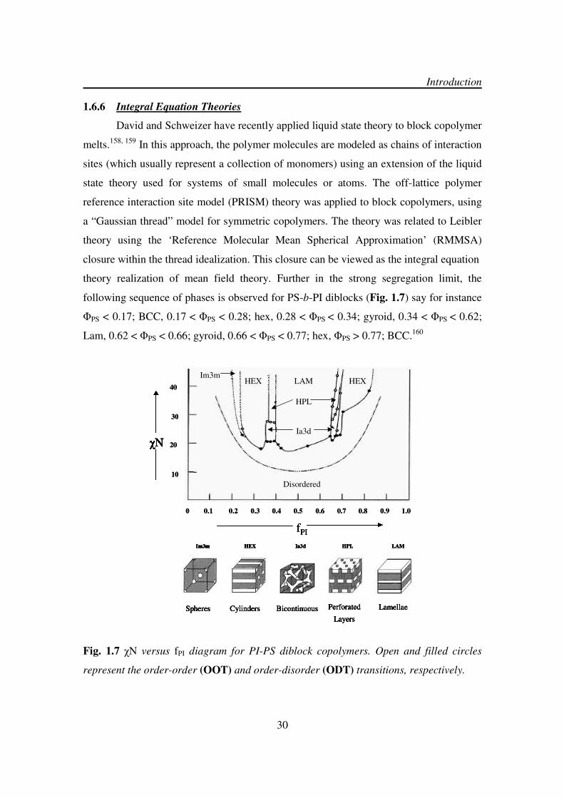
1.6.6 Integral Equation Theories
David and Schweizer have recently applied liquid state theory to block copolymer
melts.158, 159 In this approach, the polymer molecules are modeled as chains of interaction
sites (which usually represent a collection of monomers) using an extension of the liquid
state theory used for systems of small molecules or atoms. The off-lattice polymer
reference interaction site model (PRISM) theory was applied to block copolymers, using
a “Gaussian thread” model for symmetric copolymers. The theory was related to Leibler
theory using the ‘Reference Molecular Mean Spherical Approximation’ (RMMSA)
closure within the thread idealization. This closure can be viewed as the integral equation
theory realization of mean field theory. Further in the strong segregation limit, the
following sequence of phases is observed for PS-b-PI diblocks (Fig. 1.7) say for instance
ΦPS < 0.17; BCC, 0.17 < ΦPS < 0.28; hex, 0.28 < ΦPS < 0.34; gyroid, 0.34 < ΦPS < 0.62;
Lam, 0.62 < ΦPS < 0.66; gyroid, 0.66 < ΦPS < 0.77; hex, ΦPS > 0.77; BCC.160
Fig. 1.7 χN versus fPI diagram for PI-PS diblock copolymers. Open and filled circles
represent the order-order (OOT) and order-disorder (ODT) transitions, respectively.
0 0.1 0.2 0.3 0.4 0.5 0.6 0.7 0.8 0.9 1.0
fPI
χN χN
10
20
30
40
Disordered
Im3mHEX LAM HEX
HPL
Ia3d
Im3m HEX Ia3d HPL LAM
Spheres Cylinders Bicontinuous Perforated
Layers
Lamellae
Im3m HEX Ia3d HPL LAM
Spheres Cylinders Bicontinuous Perforated
Layers
Lamellae
0 0.1 0.2 0.3 0.4 0.5 0.6 0.7 0.8 0.9 1.0
fPIfPI
χN χN χN χN χN χN
10
20
30
40
Disordered
Im3mHEX LAM HEX
HPL
Ia3d
Im3m HEX Ia3d HPL LAM
Spheres Cylinders Bicontinuous Perforated
Layers
Lamellae
Im3m HEX Ia3d HPL LAM
Spheres Cylinders Bicontinuous Perforated
Layers
Lamellae
Introduction

31
1.6.7 Nanoscale Morphologies generated by Self-Assembly of Diblock Copolymers
In diblock copolymers two polymer segments are covalently joined to one
another. Self-assembly or phase segregation on nm length scales is governed mainly by
three parameters viz. total polymer length N, interaction parameter χ and relative block
length or volume fraction f. In general four stable morphologies (Fig. 1.8) have been
observed in a wide variety of diblock copolymers depending upon the block length f
namely short/long: spheres in matrix, ~20%: cylinders, ~33%: gyroid and equal lengths:
lamellar.
Fig. 1.8 Some morphologies for linear AB diblock copolymers.
1.6.8 Complex Phases in Block Copolymers
Recently, a number of so-called complex phases, such as the bicontinuous gyroid
(Fig. 1.9) and perforated layer structures have been identified. The former is an
equilibrium structure, whereas the latter seems to be a metastable structure observed
during transformation to and from the gyroid structure (a term coined by Seddon).161 The
gyroid phase (Ia3d symmetry) was discovered independently by two groups in 1994.162
SPHERES
(diameter ~ 150Å)
CYLINDERS GYROID (DD) LAMELLAE
(spacing ~ 500Å)
f = 0.1 f = 0.2 f = 0.3 f = 0.5
POLYMER A
(NA units)
POLYMER B
(NB units)
BLOCK JUNCTION
f = NA
NA + NB
SPHERES
(diameter ~ 150Å)
CYLINDERS GYROID (DD) LAMELLAE
(spacing ~ 500Å)
f = 0.1 f = 0.2 f = 0.3 f = 0.5
POLYMER A
(NA units)
POLYMER B
(NB units)
BLOCK JUNCTION
f = NA
NA + NB
Introduction

32
Schulz et al. using SANS, observed this phase on heating a mixture of polystyrene-b-
poly(2-vinylpyridine) diblocks shear-oriented in the hexagonal phase. The gyroid phase
developed epitaxially from the hexagonal phase. Further Hajduk et al. used TEM and
SAXS to determine the morphology of a PS-b-PI diblock with ΦPS = 0.33 and found the
SAXS data to be consistent with an Ia3d space group.163
There have been many
misassignments of structures as being ordered bicontinuous double diamond (OBDD,
space group Pn3m) that is based on a tetrahedral arrangement of channels when in fact
they were gyroid that has a Ia3d symmetry and is based on a tripod arrangement of
channels.
Fig. 1.9 Structures belonging to space group Ia3d (gyroid) and space group Pn3m
(‘double diamond’).
Further, Bates and coworkers had largely explored the existence of second class of
complex phases namely the modulated and perforated layer structures (Fig. 1.10). 164, 165
Hexagonal modulated lamellar (HML) and hexagonal perforated layer (HPL) structures
were observed on heating PEP-b-PEE, PE-b-PEP and PE-b-PEE diblock copolymers,
where PEP is poly(ethylene-propylene), PEE is poly(ethyl ethylene) and PE is
poly(ethylene).
Gyroid OBDDGyroid OBDD
Introduction

33
Fig. 1.10 Representation of the hexagonal-perforated lamellar (HPL) and the
hexagonal-modulated lamellar (HML) phases.
1.6.9 Microphase Separation in Multiblock Copolymers such as ABC-Triblock
Copolymers, CBAB-Tetrablock Copolymers and CBABC-Pentablock
Copolymers etc.
The phase behavior of multiblock copolymers is even more rich and complex in
contrast to two component diblock and triblock copolymers. An important driving force
for the structure formation in these polymers is the relative strength of incompatibilities
between the components.166 A combination of block sequence (ABC, ACB, BAC),
composition and block molecular weights provides enormous parameter space for new
morphologies (Fig. 1.11).
Fig. 1.11 Some morphologies for linear ABC triblock copolymers.171, 167
HPL HML
A B C
a b c d
e f g h
i j k l
A B C
a b c d
e f g h
i j k l
Introduction

34
One can tailor the properties of each phase with polymer block selection leading
to precise control of feature size with block lengths (1-100 nm). Stadler et al. have
recently discovered a number of remarkable new morphologies in PS-b-PB-b-PMMA
triblock copolymers and their hydrogenated analogues such as PS-b-PEB-b-PMMA (Fig.
1.12).168-171
The common features of the polymers exhibiting this complex phase
behaviour are that the midblock is the minority component and that the incompatibility
between the outer blocks is much weaker than the incompatibility of each of these blocks
with respect to the midblock. The morphologies were investigated by TEM using a
selective staining agent such as OsO4 for the PB domains in PS-b-PB-b-PMMA and RuO4
for PS-b-PEB-b-PMMA as it stains both the PS and PB domains.
Fig. 1.12 Microphase separated morphologies of ABC triblock copolymer
(Polystyrene-b-Polybutadiene-b-Polymethyl methacrylate). 172
Introduction

35
1.6.10 Microphase Separation and Nanolithography
Nanoscale chemical patterns written on a substrate can direct the self-assembly of
polymer overlayers with remarkable precision. These polymer films, in turn, can be used
as templates for nanofabrication. Nanolithography/nanopatterning exploits the
microphase separation behavior of block copolymers (Fig. 1.13) in the design and
fabrication of semiconductors, chips, integrated circuits, microprocessors and memory
storage devices.222, 223
Fig. 1.13 Self-Assembly of block copolymers on substrates. PS-b-PMMA (diblock
copolymer) - it contains two polymer chains, of PS (blue) and PMMA (red). The polar
PMMA block adsorbs to a uniformly polar substrate (a) driving the PS and PMMA
lamellae, with a period of about 50 nm, to lie parallel to the substrate (b) if instead, the
substrate is patterned with alternating polar and nonpolar stripes (c) with a period that
is similar to that of the PS-b-PMMA, the block copolymer self-assembles epitaxially, with
lamellae forming perpendicular to the surface and in precise register with the underlying
pattern (d) further chemical modification of the block copolymer film, such as
depolymerization of the PMMA block (e) can translate the original chemical pattern on
the substrate into a template for patterned functional materials.
Introduction

36
1.7 Conducting Polymers
Conducting polymers are conjugated polymers having an extended delocalized π-
electron system through which the electrons can move from one end of the polymer to the
other. All conjugated polymers (Fig. 1.14) have a σ-bond backbone of overlapping sp2
hybrid orbitals. The remaining out-of-plane pz orbitals on the carbon (or nitrogen) atoms
overlap with neighboring pz orbitals to give π-bonds. Polyaniline (PAN) and poly(N-
vinylcarbazole) (PVCZ) etc are well known conjugated polymer systems, with the
nitrogen pz orbital assisting the delocalisation of the π-electrons. In polymers such as
polyacetylene (PA) and polyaniline (PAN) the delocalization results in a single
(degenerate) ground state, whereas in other polymers the alternating single and double
bonds lead to electronic structures of varying energy levels. In this regard three classes of
conjugated polymers have shown potential applications for example in photovoltaic
devices and optoelectronic materials in recent years namely, poly(p-
phenylenevinylenes)173, 174
, polyanilines175-178
and polythiophenes.179-181
Fig. 1.14 Typical conjugated polymeric systems having an extended π-electron
system.
n
n
N
H n
Sn
N
H n
Fe
n
Polyferrocenylene Poly( p-phenylene vinylene)PPV
Poly( p-phenylene)
Polythiophene (PT) Polypyrrole (PPy) Polyaniline (PAN)
Introduction

37
In the year 1977 it was shown for the first time by MacDiarmid et al. that
chemical doping182
of these materials resulted in increased electron conductivities over
several orders of magnitude. Treatment with halogen was called “doping” by analogy
with the doping of semiconductors. The “doped” form of polyacetylene had a
conductivity of 105 S/m, which was higher than any previously known polymer.
183-185
This discovery captured the thoughts for developing materials with important
optoelectronic properties of metals and desirable mechanical properties, with processing
advantages of polymers and their low cost. Today conducting plastics are being
developed for many uses, such as in corrosion inhibitors, compact capacitors, antistatic
coating, electromagnetic shielding of computers and in “smart” windows that can vary
the amount of light they allow to pass etc. A second generation of electric polymers has
also appeared such as in transistors, light-emitting diodes and lasers.
Conjugated polymers exhibit electron-hole conduction similar to conventional
semiconductors and this effect is enhanced by chemical doping. A dopant is required to
introduce charge carriers in the form of extra electrons or “holes” in the material. A hole
is a position, where an electron is missing. When an electron jumps in from a neighbor
and fills such a hole, a new hole is created and so on allowing charge to migrate a long
distance. Separating the electron-hole pairs produces electrical currents. Both n-type
(electron donating - e.g. Na, K, Li, Ca, tetrabutylaluminium) and p-type (electron
accepting - e.g. I2, PF6, BF6, AsF6) dopants have been utilized to induce an insulator-to-
conductor transition in electronic polymers.
[CH]n + 3x/2 I2 → [CH]nx+ + xI3¯ Oxidative Doping
[CH]n + xNa → [CH]nx¯
+ xNa
+ Reductive Doping
The doping procedures involve exposing the polymer films or powders to vapors or
solutions of the dopant, or by electrochemical means. The polymer backbone and dopant
ions form new three-dimensional structures. The doped polymer is thus a salt. However,
it is not the counterions, I3¯ or Na+, but the charges on the polymer that are the mobile
charge carriers. By applying an electric field perpendicular to the film, the counter ions
Introduction

38
can be made to diffuse from or into the structure, causing the doping reaction to proceed
backwards or forwards. In this way the conductivity can be switched off or on. Different
conductivity ranges have been used so as to classify materials such as conductors (104 to
106 S/cm), semiconductors (10
2 to 10
-12 S/cm) and insulators (10
-12 to 10
-20 S/cm).
186
1.7.1 Band Theory of Conductivity
The quantum mechanical overlap of pz orbitals actually produces two orbitals, a
bonding (π) orbital and an antibonding (π*) orbital. The lower energy π orbital produces
the valence band and the higher energy π* orbital forms the conduction band. The
difference in the energy between the two levels produces the band gap that determines the
optical properties of the material. Most semiconducting polymers appear to have a band
gap that lies in the range 1.5-3.0 eV, which makes them ideally suited as optoelectronic
devices working in the optical light range. The charge conduction mechanism appears to
be more complex for the conducting polymers than for inorganic semiconductors. After
the excitation of an electron from the valence band to the conduction band, the resulting
electron and hole are bound together and their motion through the material is coupled.
These coupled moieties are known as excitons and are responsible for the unusual
electronic properties of polymeric systems. One needs to split the exciton so that the
holes and electrons can move freely towards opposite electrodes. The use of electron
acceptors dopants such as I2, TCNE (tetracyanoethylene), TCNQ (tetracyanoquinoline)
etc provides interfaces along the polymer network wherein the splitting of excitons can
take place and hence the probability of electron transfer between the polymeric units gets
increased. For instance in polyferrocenylenes after partial oxidation the presence of
ferrocene and ferrocenium units splits the exciton and has conductivity (10-5
S/cm)187-189
in comparison to the undoped polyferrocenylene.
Introduction

39
1.8 Scope/Motivation of the Work
The increasing interest in functional block copolymers having electrically
conducting substructure190-192 has led to many developments in this field particularly with
respect to PFS containing block copolymers.193-195
Recently the work conducted by
Rehahn et al. demonstrated196
an efficient method for the synthesis of diblock copolymers
PFS-b-PMMA using FS and MMA monomers wherein PMMA plays the thermoplastic’s
part with potential further benefit as a photoresist in lithographic processes. The blocks
were found to be rather incompatible leading to microphase separation. The phase
behaviour in the medium segregation limit yielded three classic micromorphologies
namely spheres, cylinders and lamellae.197
The bicontinuous gyroidic morphology was
observed for low molecular weight materials and high annealing temperatures.198
These
bicontinuous phases combined the PMMA’s mechanical properties with the benefits of
the functional PFS block in an ideal manner. But the main problem and drawback of this
bicontinuous phase was the high content of PFS (ΦPFS ~ 0.4), which is very expensive to
synthesize both with respect to time and resources. So the important goal of this research
work was to lower the volume fraction of PFS block without losing its well-defined
micromorphology and to investigate the influence of morphology on the conductivity of
these functional materials both in the undoped/doped state.
1.9 Strategy
A strategy that might allow the realization of low volume fraction functional PFS
blocks without losing its well-defined micromorphology consisted of the preparation of
CBABC type pentablock copolymers, having long thermoplastic A and C blocks together
with two short functional B blocks formed by PFS. In combination with polystyrene PS
(hard, brittle) forming nonpolar domains and polymethyl methacrylate PMMA (excellent
mechanical, thermal and chemical properties) forming polar domains, well defined
pentablock copolymers of CBABC type (PMMA-b-PFS-b-PS-b-PFS-b-PMMA) had to
be synthesized.199 With the dilution of functional PFS subunits upon their implementation
into pentablock copolymers, a variety of fascinating morphologies can be expected.172
Introduction

Chapter 2
Synthesis and Polymerization of
[1]Dimethylsilaferrocenophane

40
2.1 Synthesis of Monomer (FS)
The synthesis of [1]dimethylsilaferrocenophane (FS) is a two-step reaction
involving50 dilithiation of ferrocene followed by cyclization with
dichlorodimethylsilane109
as shown in the Scheme 9.201-204
The first step involves
lithiation of ferrocene (5) in hexane at room temperature using two equivalents of n-BuLi
in the presence of tetramethylethylenediamine (TMEDA) to obtain dilithioferrocene (6).
TMEDA functions as a catalyst by breaking up the less reactive aggregated structures of
butyllithium (hexamer) by coordinating to lithium. With the addition of TMEDA in the
reaction mixture the ferrocene dissolved completely turning the reaction mixture amber
in color.
After the addition of n-BuLi the change of color of the reaction mixture from amber to
red indicated the beginning of lithiation. In about an hour a yellow-orange precipitate of
dilithiated ferrocene was observed. Reaction of (6) with dichlorodimethylsilane in dry
diethylether at -80 ºC yielded the red crystalline [1]dimethylsilaferrocenophane (7). A
slight excess (ca. 4.5 mol% over the exact stoichiometric amount) of
dichlorodimethylsilane was preferred to avoid formation of oligomers. This ensured that
both the lithiated sites of ferrocene react with the same molecule of
dichlorodimethylsilane leading to cyclization and thereby minimizing oligomerization.
However it still contained some oligomers and was not pure enough for living anionic
polymerization.
Fe Fe
Li
Li
Si
CH3
CH3
Fe
Scheme 9
(5) (6)
[1]Dimethylsilaferrocenophane
(7)
* TMEDA
n-BuLi/TMEDA
n-hexane, RT
16-18h
diethylether, -80
SiMe2Cl
2
°C
16-18h
Synthesis and Polymerization of [1]Dimethylsilaferrocenophane
41
2.2 Purification of Monomer (FS)
In living anionic polymerizations, the high reactivity of anionic centers towards
atmospheric moisture, oxygen, carbon dioxide and other contaminants demands highly
pure monomeric materials in order to avoid premature living chain termination.26
If full
use of the living character of the anionic systems is desired then all the possible
impurities capable of deactivating the initiator and the propagating chain ends must be
removed from the polymerization mixture. The monomer purity determines the
polydispersity index of the polymer formed and its compositional homogeneity, which in
turn is a further crucial parameter for microphase separation and phase behaviour of the
domains. Manners et al. had suggested a purification procedure involving three cycles of
successive high vacuum sublimation (0.005 mmHg, 40 °C) and recrystallizations from
hexanes (-15 °C). However the purification procedure was revisited196
and various
drying agents were tried out (Fig. 2a). When fluorenyllithium (pKa = 19), which is only
slightly reactive206
as compared to other organolithium compounds, was used for cleaning
the protic impurities present in crude FS monomer, formation of a large amount of
oligomer was observed. In the case of triphenylmethyllithium, the formation of
triphenylmethane took place, which sublimed along with the FS monomer thereby
preventing efficient purification. Further, triphenylmethane reacted with the initiator n-
BuLi during the FS polymerization. Triethylaluminium and dibutylmagnesium, which are
very common drying agents for monomers such as styrene and methacrylates could not
be used as they also sublimed with the FS monomer at 40 ºC. Finally, out of LiAlH4 and
CaH2, the latter turned out to be the best reactive drying agent in THF as a solvent. The
FS monomer was dissolved in THF and CaH2 (~1 g) was added to the same. The solution
was stirred overnight in the glove box at room temperature.
Synthesis and Polymerization of [1]Dimethylsilaferrocenophane
42
Fig. 2a Various drying agents used for FS monomer purification (7).
Tetrahydrofuran was removed under reduced pressure on a high vacuum line. Finally, the
FS monomer was separated from CaH2 by means of sublimation at 40 ºC. This step of
stirring the monomer over CaH2 in THF was coupled with the Manners et al. purification
steps. Thus the crude FS monomer after lithium chloride separation was subjected to the
following sequence of purification steps:
(i) Sublimation at 50 ºC under reduced pressure on to a cold probe at 3 ºC.
(ii) Recrystallization from n-hexane at -60 ºC.
(iii) Dissolution in 20 mL freshly distilled THF and stirring over CaH2 (24 h).
(iv) Removal of THF and drying (4 h) under vacuum.
(v) Sublimation at 40 ºC under reduced pressure on to a cold probe at 3 ºC.
(vi) Recrystallization from n-hexane at -60 ºC.
(vii) Dissolution in 20 mL freshly distilled THF and stirring over CaH2 (24 h).
(viii) Removal of THF and drying (4 h) under vacuum.
(ix) Last sublimation at 40 °C under reduced pressure on to a cold probe at 3 °C.
Li+
C
Li+
Fluorenyllithium
AlEt3 Bu2Mg LiAlH4CaH
2
Triphenylmethyllithium
Synthesis and Polymerization of [1]Dimethylsilaferrocenophane

43
The complete sequence of purification yielded about 60-65% of the pure
[1]ferrocenophane that was good enough for anionic polymerization. Further a 20 times
expansion of the vertical scale of the 1H-NMR spectrum (Fig. 2b) of a solution
containing 15 mg of (7) in 0.5 mL of C6D6 showed no extra signals apart from those for
the [1]dimethylsilaferrocenophane and benzene.
Fig. 2b 500 MHz 1H-NMR spectrum of FS monomer (7).
Synthesis and Polymerization of [1]Dimethylsilaferrocenophane
7.5 7.0 6.5 6.0 5.5 5.0 4.5 4.0 3.5 3.0 2.5 2.0 1.5 1.0 0.5 0Chemical Shift (ppm)
0
0.05
0.10
0.15
0.20
0.25
Inte
nsity
-Si(CH3)2
CpCp
Benzene-d6
0.3
7
3.9
5
4.4
2
7.1
6
Si
CH3
CH3
Fe
(7)
[1]Dimethylsilaferrocenophane
7.5 7.0 6.5 6.0 5.5 5.0 4.5 4.0 3.5 3.0 2.5 2.0 1.5 1.0 0.5 0Chemical Shift (ppm)
0
0.05
0.10
0.15
0.20
0.25
Inte
nsity
-Si(CH3)2
CpCp
Benzene-d6
0.3
7
3.9
5
4.4
2
7.1
6
Si
CH3
CH3
Fe
(7)
[1]Dimethylsilaferrocenophane

44
2.3 Living Anionic Polymerization of [1]Dimethylsilaferrocenophane
2.3.1 Anionic Ring Opening Polymerization Initiated by n-BuLi
The polymerization reaction was performed by the addition of n-BuLi in a THF
solution of [1]dimethylsilaferrocenophane inside the glove box (Scheme 10). The color
of the solution changed from red to amber in about 10 min indicating the start of
polymerization. The PFS polymer obtained after precipitation into n-hexane and drying
was analyzed by SEC for its molecular weight distribution. An SEC elugram shown in
Fig. 2c represents a PFS polymer (8) having a narrow molecular weight distribution with
PDI and Mn of 1.02 and 25,000 g·mol-1
respectively.
Fig. 2c A typical SEC trace of polymer PFS (8).
Detector Response
Retention Time (min)
2000
4000
6000
8000
18 20 22 24 2826 30
10000
12000
Detector Response
Retention Time (min)
2000
4000
6000
8000
18 20 22 24 2826 30
10000
12000
n
H
Si
CH3
CH3
FeSi
CH3
CH3
Fe
Scheme 10
Polyferrocenyldimethylsilane
Bu
(8) [1]Dimethylsilaferrocenophane
(7)
FSPFS
n-BuLi/ THF
RT
Synthesis and Polymerization of [1]Dimethylsilaferrocenophane

45
2.3.2 Influence of Impurities on FS Polymerization Initiated by n-BuLi
To demonstrate the influence of impurities on FS polymerization by n-BuLi the
FS monomers obtained by two different purification procedures were employed. A
sample of crude FS was sublimed, recrystallized at -60 ºC and again sublimed after
stirring over CaH2 in THF (A). Further another sample was subjected to complete nine-
step purification procedure as explained in section 2.2. Equal amounts of each of them
were polymerized by the usual procedure. The experimental data obtained from these two
experiments are summarized and compared in Table 2a. Comparison of the calculated
and observed Mn values showed that in sample (A) there were significant amounts of
impurities that killed most of the initiator molecules, which resulted in quite high
molecular weight of PFS polymer (8) in comparison to calculated. While in case of
sample (B) the complete cycle of purification led to the significant removal of impurities
thereby minimizing chain termination and giving a polymer PFS with Mn close to the
calculated value.
Table 2a Polymerization of FS (7) obtained by two different purification procedures
Sample* FS
(mg)
Initiator
(µL)
Reaction
Time
(min)
Mn (g/mol)
Calculated
Mn (g/mol)
Observed PDI
A 550 20 40 17200 35250 1.12
B 552 20 40 17250 19500 1.04
* Sample A was purified by one sublimation, one recrystallization and one stirring over CaH2 in THF whereas
sample B was purified by three sublimations, two recrystallizations and two stirrings over CaH2 in THF
(complete series of purification steps).
2.3.3 Investigation of the ‘Living Character’ of Polymerization
The synthesis of a multiblock copolymer like PMMA-b-PFS-b-PS-b-PFS-b-
PMMA containing two functional PFS blocks is very sensitive to the ‘Living Character’
of FS polymerization. The living FS ends initiate the polymerization of the two terminal
PMMA blocks. Therefore a good understanding of the living character of FS
polymerization is quite important in this context. This is with respect to the pentablock
Synthesis and Polymerization of [1]Dimethylsilaferrocenophane

46
copolymer syntheses as the presence of a living system allows one to achieve different
molecular weights while ensuring all the time a narrow distribution, which on the other
hand is an essential requirement for microphase separation of the individual domains. To
investigate the ‘Livingness’ of FS polymerization with regard to the monomer obtained
by series of modified new purification steps, the monomer:initiator ratio was varied from
10:1 to 250:1 in ten different n-BuLi initiated polymerization experiments. All these
experiments yielded monodisperse PFS homopolymers (PDI = 1.02-1.08) having
molecular weights ranging from Mn = 1950-62750 g·mol-1 (Table 2b). A linear plot of
Mn (g·mol-1
) vs. mole ratio of monomer:initiator (Fig. 2d) clearly suggested the existence
of a living system under experimental conditions. The observed molecular weights in
Table 2b are in close agreement to the calculated values for all the experiments that
support the ‘living’ character of FS polymerization.
Table 2b Anionic ROP of FS (7) initiated by 1.6 M n-BuLi in hexanes
Exp M:I Monomer
(mg)
Initiator
(µL)
Reaction
Time
(min)
Mn
(g·mol-1
)
Calculated
Mn
(g·mol-1
)
Observed
PDI
1. 10:1 213 55 40 2420 1950 1.08
2. 20:1 387 50 40 4838 4200 1.07
3. 40:1 620 40 40 9688 10100 1.05
4. 60:1 697 30 40 14520 15500 1.04
5. 80:1 620 20 40 19375 21500 1.02
6. 100:1 775 20 40 24200 25600 1.03
7. 140:1 542 10 40 33875 35500 1.04
8. 170:1 658 10 40 41125 43000 1.06
9. 200:1 775 10 40 48438 50550 1.07
10. 250:1 968 10 40 60500 62750 1.07
Synthesis and Polymerization of [1]Dimethylsilaferrocenophane

47
Fig. 2d A plot of the mole ratio of monomer: initiator vs. Mn (g/mol) for the n-BuLi (1.6
M in hexane) initiated synthesis of PFS (8).
In separate experiments, addition of another small lot of monomer FS (7) to the
living polymer system and termination by few drops of methanol yielded PFS polymers
(8), which also showed the expected increase in molecular weight characteristic of a
living process (Table 2c).
Table 2c Further addition of FS (7) to the polymerization solution
Exp Monomer
(mg)
Initiator
(µL)
Reaction
Time
(min)
Mn
(g·mol-1
)
Calculated
Mn
(g·mol-1
)
Observed
PDI
1. 620 40 40 9688 10100 1.05
2. Monomer
added 200 12800 13200 1.05
Thus all these polymerization experiments clearly show that the FS polymerization is
‘living’ in character under the chosen conditions.
0 50 100 150 200 250 300
0
10000
20000
30000
40000
50000
60000
70000
Mn (g/mol)
Ratio of Monomer : Initiator
Synthesis and Polymerization of [1]Dimethylsilaferrocenophane

Chapter 3
Synthesis and Characterization of
PMMA-b-PFS-b-PS-b-PFS-b-PMMA
Pentablock Copolymers

48
2+ 2 Li C10H8
- 2 C10H8
+CH2 CH2CH CH
- -Li+
Li+
+ 2 (x-1) S
S
CH2 CH2CH CHCH2 CH2CH CH- -Li
+ Li+
x-1 x-1
+ 2y FS
CH2 CH2CH CHSi Si
CH3
CH3
CH3
CH3
-Li
+
x xSi
CH3
CH3
Fe
Si
CH3
CH3
FeFe Fe
-Li
+
y-1y-1
1) + 2 DMSB, + 4 DPE
2) + 2 z MMA
3) + methanol
CH2 CH2CH CHSi Si
CH3
CH3
CH3
CH3
x xSi(CH2)3CH2
CCH2CH
C
CH3
O
OCH3
CH3
CH3
Fe
Si (CH2)3 CH2
C CH2 C H
CH3
C
OCH3
OCH3
CH3
Fe
yyz zmm
1
2
3
The nucleophilicity of the living chain ends estimated on the basis of pKa values
determines the order and sequence of the blocks. The pKa for living polystyryl anions is
43 (in DMSO), 66 39 for polyferrocenyl209 and 27-28 for polymethyl methacrylate chain
ends (pKa of ethyl acetate as a model substance: approx. 27-28).210
The pKa values
clearly explain that with these above mentioned three monomers one has to polymerize
styrene (S) first followed by [1]dimethylsilaferrocenophane (FS) and finally methyl
methacrylate (MMA) by means of sequential anionic polymerization steps (Scheme 11).
This chapter deals with the synthesis and characterization of well-defined
pentablock copolymers from styrene as the medium-size central A block, 207
PFS as the
small functional B block, and using the 1,1-dimethylsilacyclobutane (DMSB)-mediated
1,1-diphenylethylene (DPE) end-capping technique, PMMA as the long final C block.199
Lithium naphthalide was selected as a difunctional initiator for styrene polymerization
first.25, 208, 49 The employed preparative strategy should lead to an efficient synthesis of
three component pentablock copolymers meeting the criteria of high block efficiency and
narrow molecular weight distribution.
Scheme 11
Synthesis and Characterization of PMMA-b-PFS-b-PS-b-PFS-b-PMMA Pentablock Copolymers

49
3.1 Difunctional Initiator ‘Lithium Naphthalide’
3.1.1 Radical Anion
Naphthalene reacts with alkali metals such as lithium and sodium in THF as a
solvent to form stable solutions of the corresponding radical anion (Fig. 3a). These
solutions when stored at –20 ºC remain active for about 3-4 weeks.
Fig. 3a Naphthalene radical initiator system, M= Li or Na.
Lithium was chosen over sodium because of its small size and covalent nature of bonding
with alkyl groups. With lithium as the counterion one has a good balance between the
kinetics of initiation and propagation that is crucial for living anionic polymerization.206
3.1.2 Analysis of the Initiator Solution
The concentration of the lithium naphthalide initiator solution used for the
synthesis of pentablock copolymers was back calculated from the polymerization of
styrene at -50 ºC. SEC analysis (Fig. 3b) gave Mn = 19,850 g·mol-1
and PDI = 1.02, from
which the concentration of the lithium naphthalide initiator solution was calculated to be
0.504 M.
Fig. 3b SEC chromatogram of polystyrene polymerized by lithium naphthalide initiator.
Synthesis and Characterization of PMMA-b-PFS-b-PS-b-PFS-b-PMMA Pentablock Copolymers
+ M M+
.
0 5 10 15 20 25 30 35
0.00
0.02
0.04
0.06
0.08
0.10
0.12
0.14
Polystyrene
Mn = 19850 gmol
-1
Mw = 20250 gmol
-1
PDI = 1.02
Detector
Response
Retention Time (min)

50
3.2 DMSB as “Carbanion Pump” for Efficient End-Capping/Trapping of Living
PFS Chain Ends during MMA Polymerization
Attempts to polymerize MMA by the living PFS chain ends failed due to their
high nucleophilicity causing predominant attack on the carbonyl group and thereby
leading to limited monomer conversion and metal methoxide formation.211, 116, 196
In order
to make a selective attack on the double bond of MMA possible, the living precursor PFS
chain ends must therefore be modified in such a way that its nucleophilicity is reduced
and the steric requirements are also increased. This secondary reaction involving the
nucleophilic attack on the carbonyl group can be limited when a sterically hindered
initiator system45
like diphenylhexyllithium, formed by the reaction of n- or sec-
butyllithium with (one unit of) 1,1-diphenylethylene, is used in a polar solvent (THF)
below -70 ºC. MMA polymerization then becomes a living process. This end-capping
reaction in THF is quite fast at room temperature and takes place quantitatively as
employed by Jérôme et al. in the synthesis of MSBSM pentablock copolymers from
butadiene (B), styrene (S) and methyl methacrylate (M) monomers.212
With the usage of DPE, the living chain ends prior to MMA polymerization are
less reactive (pKa of diphenylmethane: approx. 32) 206
than the PFS chain ends (pKa:
39).209 The applicability of this method to the synthesis of PFS-b-PMMA was examined
and it was found that the reaction between PFS living chain ends and DPE was very slow
at room temperature in the glove box and even after 2 days only 80 % conversion took
place. These observations were supported by the determination of unreacted DPE by GC
against decane as internal standard and MALDI TOF mass spectrometry of the
terminated reaction product by methanol.213
In order to increase the efficiency of the end-capping/trapping reaction with
respect to both conversion and time, one needs to activate the living PFS chain ends in
relation to the reaction with DPE. In the year 2001, a Japanese research group of
Kawakami proposed216
the concept of a carbanion pump wherein a silacyclobutane
having high ring distortional energy214 was used to convert an oxyanion into a carbanion,
which was efficiently trapped by DPE and used to polymerize methyl methacrylate in a
controlled manner at -78 ºC (Fig. 3c).
Synthesis and Characterization of PMMA-b-PFS-b-PS-b-PFS-b-PMMA Pentablock Copolymers

51
Fig. 3c Schematic representation of the DMSB based Carbanion Pump.
The use of DMSB, which besides increasing the nucleophilicity of the PFS chain ends,
also shifts the active reaction center from the ferrocene ring to one silicon and three
carbon units in sequence. Thus some steric hindrances existing in the reaction of living
PFS with DPE earlier are reduced appreciably. A mole ratio of 1:4:2 for Initiator:DPE:
DMSB was employed along their addition to the reaction mixture in a sequence wherein
DPE was added first followed by DMSB so as to avoid unwanted homopolymerisation of
silacyclobutane.215
DPE reacts slowly with the living PFS chain ends. The actual end-
capping starts with the addition of DMSB where the alkyl lithium chain ends formed
instantaneously and immediately react with DPE present in excess in the reaction
mixture.
3.3 Pentablock Copolymer Synthesis
At first, an appropriate quantity of styrene was added to the solution of lithium
naphthalide in tetrahydrofuran at -50 ºC. The color of the reaction mixture turned yellow
due to the living polystyryl anions. When the polymerization was complete, the reaction
mixture was allowed to come to room temperature. A small test sample of 1 was taken
Synthesis and Characterization of PMMA-b-PFS-b-PS-b-PFS-b-PMMA Pentablock Copolymers
O Li+
Si
O Si CH2
Li+ DPE
O Si
C Li+
n MMA
PMMA
n MMA
Nucleophilicity
Increasing

52
from the reaction flask and quenched with degassed methanol for subsequent analysis. A
solution of FS in THF was then added to the reaction mixture thereby changing the color
of the reaction mixture to red and gradually to amber. After complete conversion and
withdrawl of a further small sample of 2 for analysis, the living chain termini of the PFS-
b-PS-b-PFS triblock copolymer 2 were end capped by adding a mixture of 1,1-
diphenylethylene and 1,1-dimethylsilacyclobutane in sequence.216, 196
Subsequently,
MMA was added at -80 ºC to grow onto the formed bifunctional macroinitiator 2 in a
controlled way and the reaction mixture turned yellow immediately. Finally, the whole
reaction mixture was deactivated by degassed methanol. The final products 3, as well as
samples 1 and 2 taken during the synthesis, were analyzed using (SEC) Size Exclusion
Chromatography (Fig. 3d).
One can clearly see from the elution curves of the PS as well as that of the PFS-b-
PS-b-PFS triblock copolymer 2 that they are very narrow and do not show any evidence
of a bimodal or trimodal molecular weight distribution. Thus on the basis of the elugrams
we can say that there is almost no termination when FS is grafted onto the difunctional
polystyrene chains 1. Only during DPE/DMSB end-capping and subsequent addition of
MMA to the bifunctional PFS-b-PS-b-PFS macroinitiator, approx. one quarter of the
living chain ends terminate. The content of terminated species was roughly estimated by
graphic separation of the coincident SEC peaks, assuming Gaussian distribution of the
length of the individual block species and comparison of the peak areas. Based on this
analysis, approx. 20 % of PFS-b-PS-b-PFS-b-PMMA tetrablock copolymer and 5 % of
PFS-b-PS-b-PFS triblock copolymer are formed in addition to 75 % of the desired
PMMA-b-PFS-b-PS-b-PFS-b-PMMA pentablock system during the final grafting step.
This result reflects a higher degree of termination when MMA grows onto living PFS
chain termini in a triblock copolymer such as 2 compared with the growth onto pure PFS
macroinitiators as described recently.196
This might be caused by traces of impurities in
the solvent or in the FS monomer, which play a more significant role here because of the
very low concentration of living centers present during the pentablock copolymer
synthesis.
Synthesis and Characterization of PMMA-b-PFS-b-PS-b-PFS-b-PMMA Pentablock Copolymers

53
Fig. 3d Characteristic SEC traces of PS 1 (Trace 1, Red), the PFS-b-PS-b-PFS
intermediate 2 (Trace 2, Green), and the final PMMA-b-PFS-b-PS-b-PFS-b-PMMA
pentablock copolymer 3 (Trace 3, Blue). Samples are taken during a typical
polymerization experiment according to Scheme 11.
Nevertheless, difference in reactivity of the living PFS chain ends associated with
the macroinitiator’s block copolymer architecture might be responsible as well for the
more significant chain termination observed here. Therefore, the influence of the time
provided for the DPE/DMSB end-capping on the degree of chain termination was
studied. In parallel entries, MMA was added to the reaction mixture after the interval of
15, 30, 45 and 75 min after the addition of DPE and DMSB. Multimodal distributions
such as trimodal (Fig. 3e) were obtained for 15 and 30 min time periods before the
addition of MMA indicating that the end capping was not complete and there may be
more than one kind of living species in the system such as *DPE-PFS-b-PS-b-PFS-DPE*,
*DPE-PFS-b- PS-b -PFS* and *PFS-b-PS-b-PFS* where * indicates a living chain end.
15 20 25 30
0.0
0.2
0.4
0.6
0.8
1.0
Detector
Response
Retention Time (Mins)
Trace 1 Trace 1
Trace 2 Trace 2 Trace 3 Trace 3
15 20 25 30
0.0
0.2
0.4
0.6
0.8
1.0
Detector
Response
Retention Time (Mins)
Trace 1 Trace 1 Trace 1 Trace 1
Trace 2 Trace 2 Trace 2 Trace 2 Trace 3 Trace 3 Trace 3 Trace 3
Synthesis and Characterization of PMMA-b-PFS-b-PS-b-PFS-b-PMMA Pentablock Copolymers

54
Fig. 3e Characteristic SEC traces obtained after 30 min time period for end capping
reaction leading to a trimodal distribution. (Tetrablock Major, Pentablock Minor and
Triblock about ~5%)
The best results, that is, the smallest portion of terminated chains were obtained
for 45 and 75 minute periods for end capping. This is clearly longer than during the
synthesis of PFS-b-PMMA diblock copolymers where end-capping was already complete
after 5 min.196
This result points towards some influence of the macroinitiators chain
architecture on the reactivity of the chain termini, may be through a changed aggregation
behavior of the living chain ends. Moreover, the pentablock copolymer architecture
makes efficient purification of the products difficult: the removal of tri- and tetrablock
copolymer contaminations from pentablock systems is a well-known problem associated
with multiblock copolymer syntheses.217, 218
Nevertheless an efficient procedure (section
3.4) of repeated precipitation was developed that allowed the removal of all impurities
except approximately 15% of the tetrablock species. The latter amount of tetrablock
copolymer might also be removable either by multiple repetition of the precipitation
procedure or using preparative SEC. But, the material’s micro morphologies are not
18 24 30
0.0
0.4
0.8
Detector
Response
Retention Time (min)
Pentablock
Minor portion
Pentablock
Minor portion
Trace 3Trace 3
Major portion
TetrablockTetrablock
Major portion
Trace 2Trace 2
Trace 1Trace 1
TriblockTriblock
18 24 30
0.0
0.4
0.8
Detector
Response
Retention Time (min)
Pentablock
Minor portion
Pentablock
Minor portion
Pentablock
Minor portion
Pentablock
Minor portion
Trace 3Trace 3Trace 3Trace 3
Major portion
TetrablockTetrablock
Major portionMajor portion
TetrablockTetrablock
Major portion
Trace 2Trace 2Trace 2Trace 2
Trace 1Trace 1Trace 1Trace 1
TriblockTriblockTriblockTriblock
Synthesis and Characterization of PMMA-b-PFS-b-PS-b-PFS-b-PMMA Pentablock Copolymers

55
influenced in an irreproducible way by that minor amount of tetrablock copolymers
which has the same polarity as the pentablock. Hence it was decided to continue the
investigations with respect to the bulk properties in some more detail.
3.4 Purification of Pentablock Copolymer by Means of Selective Precipitation
Attempts for the purification of the pentablock copolymer by precipitation were
made with various solvents. Three solvents namely hexane, cyclohexane and toluene
were employed for the experiments. The best results were found for cyclohexane and the
pentablock was purified by three cycles of repetitive precipitation in cyclohexane. The
crude pentablock was dissolved in THF and to this solution cyclohexane was added
dropwise. This addition of cyclohexane changes the polarity of the solvent mixture and
Fig. 3f Characteristic SEC traces of PS 1 (Trace 1, Red), the PFS-b-PS-b-PFS
intermediate 2 (Trace 2, Green), and the PMMA-b-PFS-b-PS-b-PFS-b-PMMA
pentablock copolymer 3 (Trace 3, Blue) after threefold precipitation according to the
above purification procedure.
the pentablock precipitates out along with the small quantity of tetrablock copolymer.
The triblock remains in the solution and is separated off from the precipitate by means of
20 25 30
0.0
0.4
0.8
Detector
Response
Retention Time (min)
Trace 1 Trace 1 Trace 1 Trace 1 Trace 1 Trace 1
Trace 2 Trace 2 Trace 2 Trace 2 Trace 2 Trace 2 Trace 3 Trace 3 Trace 3
20 25 30
0.0
0.4
0.8
Detector
Response
Retention Time (min)
Trace 1 Trace 1 Trace 1 Trace 1 Trace 1 Trace 1 Trace 1 Trace 1 Trace 1 Trace 1 Trace 1 Trace 1 Trace 1 Trace 1
Trace 2 Trace 2 Trace 2 Trace 2 Trace 2 Trace 2 Trace 2 Trace 2 Trace 2 Trace 2 Trace 2 Trace 2 Trace 2 Trace 2 Trace 3 Trace 3 Trace 3 Trace 3 Trace 3 Trace 3
Synthesis and Characterization of PMMA-b-PFS-b-PS-b-PFS-b-PMMA Pentablock Copolymers

56
a centrifuge (Fig. 3f). The procedure can be repeated several times, depending on the
required purity of the materials.
3.5 Molecular Characterization of the Pentablock Copolymers
A series of pentablock copolymers were synthesized by the sequential addition of the
monomers (quantities mentioned in Table 1).
Table 1 Quantities of monomers (S, FS and MMA) and initiator (I) used
for the synthesis of pentablock copolymers
Sample S
(g, mmol)
FS
(g, mmol)
MMA
(g, mmol)
I
(µmol)
A 0.28, 2.688 0.2, 0.8261 0.9, 8.989 25.2
B 0.25, 2.4 0.2, 0.8261 0.8, 7.9904 25.2
C 0.85, 8.16 0.4, 1.6522 1.2, 11.985 50.4
D 0.45, 4.32 0.2, 0.8261 0.65, 6.4919 25.2
E 0.6, 5.76 0.2, 0.8261 0.6, 5.9925 25.2
F 0.7, 6.72 0.2, 0.8261 0.5, 4.9938 25.2
G 0.75, 7.2 0.2, 0.8261 0.35, 3.4958 25.2
After synthesis, a careful molecular characterization of the materials by various
spectroscopic and chromatographic techniques was carried out. The molecular weights of
the pentablock copolymers as well as of all intermediates were determined through size
exclusion chromatography by the evaluation of the SEC elution curves vs. commercially
available polystyrene (PS) standards (see Chapter 7 Experimental). The experimentally
determined values of Mn were found to be in good agreement with the calculated Mns.
The polydispersity indices were clearly below 1.2 in all cases (Table 2).
Synthesis and Characterization of PMMA-b-PFS-b-PS-b-PFS-b-PMMA Pentablock Copolymers

57
The block lengths in the pentablock copolymers are the values expected from the
amounts of monomers and initiators used in the respective entry.
Table 2 Characterization of the PMMA-b-PFS-b-PS-b-PFS-b-PMMA pentablock
copolymers, synthesized in THF using lithium naphthalide as a difunctional initiator
Fig. 3g 1H NMR spectrum (500MHz) of a PMMA-b-PFS-b-PS-b-PFS-b-PMMA
pentablock copolymer in CD2Cl2.
φ (NMR) Block Length N
Sample Mn
(g/mol)
Pentablock
Mw
(g/mol)
Pentablock
Mn
(g/mol)
Triblock
Mn
(g/mol)
PS
PDI MMA FS S MMA FS S
A 50 000 56 000 19 500 12 000 1.12 60 13 27 300 35 104
B 51 000 57 000 20 000 11 000 1.12 59 15 26 294 35 100
C 49 000 56 000 29 000 16 500 1.14 47 16 37 248 39 150
D 50 000 57 000 27 000 18 000 1.14 45 16 39 240 39 160
E 50 000 57 500 30 000 22 000 1.15 37 13 50 207 33 208
F 51 000 58 000 34 500 27 000 1.13 29 13 58 168 33 249
G 52 000 59 000 36 500 29 000 1.13 21 15 64 125 39 285
Synthesis and Characterization of PMMA-b-PFS-b-PS-b-PFS-b-PMMA Pentablock Copolymers
7.5 7.0 6.5 6.0 5.5 5.0 4.5 4.0 3.5 3.0 2.5 2.0 1.5 1.0 0.5 0Chemical Shift (ppm)
0
0.05
0.10
0.15
0.20
0.25
0.30
0.35
0.40
0.45
Inte
nsity
3.001.69 0.470.47
[(Cp)2FeSiMe2]
(-CH3, MMA iso)
(-CH3,MMA Syn)
(br, -CH2,Ph)
(br, CHPh)
(-CH2, MMA)
(-COOCH3)
CpCp
Dichloromethane-d2(br,Ph)
(br,Ph)
(br,Ph)
0.4
8
0.8
4
1.0
0
1.2
0
1.4
7
1.8
11
.90
3.5
9
4.0
3
4.2
4
6.5
26
.60
7.0
6
Fe
C
OCH3
O
H
CH3
z
CHSi
CH3
CH3
CH
Si
CH3
CH3
y
x
x
C
OCH3
O
CH3
H
z
y
Fe

58
The pentablock copolymer was further analyzed by NMR spectroscopy. Integration of the
characteristic proton resonances (Fig. 3g) namely for the eight protons of mono
substituted cyclopentadienyl ring (δ = 4.24, 4.03 ppm), the three protons of the methyl
ester in MMA (δ = 3.59 ppm) and the five aromatic protons from the benzene ring in
styrene appearing as broad signals (δ = 6.5-7.02 ppm) along with the absorption
intensities allowed determination of the molar composition of the materials. Broad
signals typical for PMMA tacticity219, 220
were also observed viz. (δ = 1.20 ppm, PMMA
Isotactic) and (δ = 1.00 ppm, PMMA Syndiotactic). Furthermore, the degree of
polymerization of each block was estimated by combining the overall values of Mn with
the ratios of the 1H NMR integrals. The bulk densities taken for the calculation of volume
fraction φ are 1.26 g.cm-3 for PFS207, 0.906 g.cm-3 for PS and 1.15 g.cm-3 for PMMA.221
Finally detailed analysis and peak assignment was also done for the 13
C NMR spectrum
so as to complete the spectral characterization (Fig. 3h).
Fig. 3h 13
C NMR spectrum (125MHz) of a PMMA-b-PFS-b-PS-b-PFS-b-PMMA
pentablock copolymer in CD2Cl2.
Synthesis and Characterization of PMMA-b-PFS-b-PS-b-PFS-b-PMMA Pentablock Copolymers
184 176 168 160 152 144 136 128 120 112 104 96 88 80 72 64 56 48 40 32 24 16 8 0Chemical Shift (ppm)
0.1
0.2
0.3
0.4
0.5
0.6
0.7
0.8
Inte
nsity
(-SiMe2)
(-CH3,syn MMA)
(-CH3,iso MMA)
(CHPh)
(Quat C,MMA)
(CH2,Ph)
(-COOCH3,MMA)
(-CH2, MMA)
(Cp)
(Cp, ipso-C)
(Cp)
(Ph,p)
(Ph,o)
(Ph,m)
Ph,ipso C
(Ph,ipso-C)
(-COO-, PMMA)
-0.9
3
16
.95
19
.00
40
.77
44
.90
45
.23
51
.97
52
.78
71
.63
73
.47
12
6.0
21
27
.98
12
8.3
9
14
5.3
81
46
.18
17
8.0
7
Fe
C
OCH3
O
H
CH3
z
CHSi
CH3
CH3
CH
Si
CH3
CH3
y
x
x
C
OCH3
O
CH3
H
z
y
Fe

59
Thus, the strategy for the synthesis of CBABC type pentablock copolymers was
effectively realized. The block copolymers were well defined and synthesized in good
yield (75%) using lithium naphthalide as a difunctional initiator and DMSB as an
accelerator for more efficient DPE end-capping. Molecular characterization of the
materials was done by NMR spectroscopy and Size Exclusion Chromatography (SEC)
with respect to their narrow molecular weight distributions (PDI< 1.2).
Synthesis and Characterization of PMMA-b-PFS-b-PS-b-PFS-b-PMMA Pentablock Copolymers
Chapter 4
Self-Assembly of
PMMA-b-PFS-b-PS-b-PFS-b-PMMA
Pentablock Copolymers

60
This chapter describes in detail the self-assembly of PMMA-b-PFS-b-PS-b-PFS-
b-PMMA pentablock copolymers including the sample preparation and characterization
by TEM and SAXS. The huge multitude of possible microphases is determined by
composition variables, the volume fractions (φA, φB, φC) and the three Flory-Huggins
interaction parameters (χAB, χAC and χBC). In general suitable samples were prepared by
slow evaporation of a solution of the block copolymers in an appropriate solvent. The
solvent has a large influence on the formation of equilibrium morphology 224-229
of
interest. The solubility of polymers in low molecular weight solvent is described by
means of Hildebrand’s solubility parameter, which provides a guide for the solvent
selection.
4.1 Determination of Solubility Parameters
The solubility of polymers in different solvents is determined by Hildebrand
solubility parameters, which is a fundamental thermodynamic property of polymers and
is used extensively for the discussion of the miscibility of polymers in solvent and blends.
The process of dissolving an amorphous polymer in a solvent is governed by the free
energy of mixing given by
∆Gm = ∆Hm – T∆Sm 4.1a
Where, ∆Gm is the Gibbs free energy change of mixing, ∆Hm is the enthalpy change of
mixing, T is the absolute temperature, and ∆Sm is the entropy change of mixing.
Hildebrand, Scott and Scatchard230
proposed that the enthalpy change of mixing (∆Hm)
can be related to the energy of vaporization (∆Ev) by
∆Hm = V [(∆Ev1/ V1)
1/2 – (∆Ev2/ V2)
1/2] 2 Φ1Φ2 4.1b
where V is the volume of mixture (V1 + V2), ∆Evi is the energy of vaporization of species
i and Φi is the volume fraction of species i.
The solubility parameter, δi, of a liquid is defined as the square root of the cohesive
energy density (∆Evi /Vi) that describes the attraction between molecules of the material
Self-Assembly of PMMA-b-PFS-b-PS-b-PFS-b-PMMA Pentablock Copolymers

61
δi = (∆Ev
i /Vi) 1/2
4.1c
where Vi is the molar volume of species i. Thus materials with similar cohesive energy
density have quite similar intermolecular attractive forces, which explain their
miscibility. Equation 4.1b can be rewritten to give the heat of mixing per unit volume for
a binary mixture:
∆Hm/V = (δ1 – δ2) 2 Φ1Φ2 4.1d
For the Gibbs free energy of mixing (∆Gm) to be favorable i.e. negative, the heat of
mixing must be smaller than the entropic term (T∆Sm). In general (δ1 – δ2) 2 must be
small for the components to be miscible. Therefore a good knowledge of the solubility
parameter of a polymer is of fundamental significance.
The solubility parameter determination for solvents and other volatile substances
is done by calorimetric measurements of the enthalpy of evaporation (∆Hvap). Since
polymers are non-volatile and they decompose before the heat of vaporization can be
measured, their solubility parameters are determined indirectly by methods such as
refractive index231
, intrinsic viscosity232
, turbidimetric titrations233
, gas
chromatography234
and swelling measurements.235
The solubility parameter of PFS was
determined by swelling studies of a crosslinked poly(ferrocenyldimethylsilane)-
poly(carbosilane) network in various solvents (Fig. 4b).236
The solubility parameter range for the poly(ferrocenyldimethylsilane)
homopolymer was estimated by swelling studies of the weakly crosslinked gel in fourteen
different solvents with δ values ranging from 14.4 to 24.3 MPa1/2
. The best solvents for
poly(ferrocenyldimethylsilane) turned out to be tetrahydrofuran, chloroform and
dichloromethane with a solubility parameter of 18.7 MPa1/2
. Further the solubility
parameter for PS and PMMA are 18.2 MPa1/2 and 18.6 MPa1/2 respectively.221
Self-Assembly of PMMA-b-PFS-b-PS-b-PFS-b-PMMA Pentablock Copolymers

62
Fig. 4b Synthesis of a crosslinked poly(ferrocenyldimethylsilane)-poly(carbosilane)
network.236
Table 1 Hildebrand’s Solubility Parameters for various solvents221
Solvent n-Hexane Cyclohexane Ethyl acetate Toluene THF CH2Cl2 CHCl3 MEK
∆ MPa1/2
14.9 16.8 18.2 18.3 18.5 18.6 18.7 19.3
Table 2 (δ1 – δ2) 2
for Homopolymer-Solvent Pairs
Polymer n-Hexane Cyclohexane Ethyl acetate Toluene THF CH2Cl2 CHCl3 MEK
PS 10.89 1.96 0.00 0.01 0.09 0.16 0.25 1.21
PFS 14.44 3.61 0.25 0.16 0.04 0.01 0.00 0.36
PMMA 13.69 3.24 0.16 0.09 0.01 0.00 0.01 0.49
It is quite clear and evident from the above two tables that toluene, THF and
dichloromethane are the best solvents for PS, PFS and PMMA blocks in the pentablock
copolymer i.e. when no selectivity is observed. Ethyl acetate is good for both PS and
PMMA but PFS has a very low solubility in it. Further n-hexane, cyclohexane and methyl
Self-Assembly of PMMA-b-PFS-b-PS-b-PFS-b-PMMA Pentablock Copolymers
Si
CH3
CH3
Fe SiFe
Si
m
y
x
Si
MeMe
Fe
Si
Me Me
Fe
Fe
n m+
n = x+y >> m

63
ethyl ketone were also ruled out because of large differences in the solubility parameters
between them and the blocks of the pentablock copolymer.
4.2 Thermal Characterization of the Pentablock Copolymer
Thermal stability of pentablock copolymer samples was investigated so as to have
a fair idea about the appropriate/possible annealing temperatures under vacuum for film
preparation. One should avoid working very close to the decomposition temperature
while forcing microphase separation in the block copolymer melt. Thermal
characterization was therefore required to decide the safe temperature range without
causing decomposition.
4.2.1 Thermogravimetry and Thermal Stability
Thermogravimetric analysis (TGA) of the pentablock copolymer (Fig. 4c) showed
Fig. 4c TGA trace of pentablock copolymer sample A (heating rate of 10 °C min-1
).
that the decomposition started at around 300 °C. This observation is consistent with the
stability of anionically polymerized PMMA237
, which is stable up to approximately 300
°C and PFS wherein decomposition starts only at around 350 °C.238, 239
PFS
homopolymer undergoes Fe-Si-C ceramic formation when heated in the range of 450-500
°C. Polystyrene is also thermally stable upto 400 °C.145 Thus a narrow temperature range
0 100 200 300 400 500 600 700
0
2
4
6
8
10
12
Weight (%)
Temperature (°C)
Self-Assembly of PMMA-b-PFS-b-PS-b-PFS-b-PMMA Pentablock Copolymers

64
of weight loss (300-500 °C) accompanied by cross-linking and depolymerization
reactions is observed for the pentablock copolymer.
The influence of high temperature on the block copolymer films was also
investigated by means of size exclusion chromatography. Samples after annealing at
various temperatures for 24 h in vacuum were analyzed for their molecular weight
distribution. An overlay of various SEC elugrams (Fig. 4d) clearly shows that broadening
of the peak shape starts somewhere around 260 °C wherein a shoulder appears to the
right of the peak. This can be explained due to the low molecular weight portions formed
by depolymerization of PMMA.
Fig. 4d Comparison of GPC elugrams from films of pentablock copolymer D (from
CH2Cl2) after annealing in the vacuum at temperatures 160 °C to 260 °C for 24 h. (Mn =
50,000 g·mol-1
) [Volume fraction φ; MMA: 45, FS: 16, S: 39]
4.2.2 Differential Calorimetry
It has been reported203 by Manners et al. that the glass transition temperatures
(measured by DSC) of monodisperse PFS increase from 8 °C to 33 °C as the Mn value
20 30
0.0
0.2
0.4
0.6
0.8
1.0
Detector
Response
Retention Time (min)
24h at 260°C
24h at 160°C
24h at 230°C
24h at 200°C
20 30
0.0
0.2
0.4
0.6
0.8
1.0
Detector
Response
Retention Time (min)
24h at 260°C
24h at 160°C
24h at 230°C
24h at 200°C
Self-Assembly of PMMA-b-PFS-b-PS-b-PFS-b-PMMA Pentablock Copolymers

65
increases from 1800 g⋅mol-1 to 22000 g⋅mol-1 and then it remains the same for very high
molecular weight (Mn > 105). In contrast to PFS that is semi-crystalline PMMA is
amorphous and depending on the tacticity it has different glass transition temperatures.
Anionic polymerization of MMA at –78 °C yields 80 % syndiotactic PMMA having a Tg
of 128 °C.240
Further for PS the Tg ranges from 88 °C to 110 °C depending on the
molecular weight.241
The thermal transition behavior of the pentablock copolymers was investigated by DSC
(Fig. 4e). The glass transition for PFS was not observed primarily because of its low
volume fraction in the pentablock copolymer (φ = 0.13 – 0.16). The two glass transitions
for PS and PMMA were at 90 °C and 130 °C respectively which were found to be in a
similar range to those of the corresponding homopolymers thereby strongly suggesting
that the blocks are incompatible.211, 242
Thus in the solid state, the formation of
microscopic heterogeneities in composition would be expected.
Fig. 4e DSC trace of pentablock copolymer sample A (heating rate of 10 °C min-1
).
Glasumwandlung Onset 91,43 °C Mittel. 98,71 °C
Glasumwandlung Onset 124,72 °C Mittel. 130,97 °C
mW
1
°C 40 60 80 100 120 140 160 180
^exo
Self-Assembly of PMMA-b-PFS-b-PS-b-PFS-b-PMMA Pentablock Copolymers

66
4.3 Phase Behavior of the Pentablock Copolymers
The phase behavior was studied in the bulk block copolymer melt. The
pentablock copolymer films were initially cast onto glass plates from solutions (5 % w/v)
in dichloromethane, tetrahydrofuran and toluene.197
Freshly cast films were then stored in
the saturated atmosphere of the corresponding solvent for 3-4 weeks so as to induce and
drive the formation of thermodynamically stable morphologies. The micromorphologies
formed by these materials have a PFS volume fraction of φPFS = 0.13 to 0.16. All the
relevant data of the samples under further investigation are listed in Table 3.
Table 3 Molecular weight and volume fraction of the pentablock copolymer samples
investigated by TEM and SAXS.
φ (NMR) Block Length N
Sample Mn (g/mol)
Pentablock
Mw (g/mol)
Pentablock PDI
MMA FS S MMA FS S
A 50 000 56 000 1.12 60 13 27 300 35 104
B 51 000 57 000 1.12 59 15 26 294 35 100
C 49 000 56 000 1.14 47 16 37 248 39 150
D 50 000 57 000 1.14 45 16 39 240 39 160
E 50 000 57 500 1.15 37 13 50 207 33 208
F 51 000 58 000 1.13 29 13 58 168 33 249
G 52 000 59 000 1.13 21 15 64 125 39 285
When the annealing procedure was carried out at temperatures above 200 °C followed by
direct quenching of the films in ice water, apparently biphasic morphologies were
observed by TEM, which was further supported by SAXS scattering pattern. They were
either lamellar or cylindrical, depending on the PMMA’s volume fraction. Under these
annealing conditions there is rather high compatibility between PS and PFS207
and hence
low segregation tendency, which results in a homogeneous mixture of these segments
(dark grey phase in the TEM pictures). Only PMMA, which is incompatible with both
PFS and PS, creates its own phase (white phase in the TEM pictures). Consequently a
biphasic morphology is formed which assumes a lamellar structure when both φPMMA and
φPS+PFS are between 0.4 and 0.6 and is in full agreement with expected results. As an
example (Fig. 4f) shows the TEM picture of a film of sample B treated in this way.
Similar pictures were obtained for samples A, C and D under analogous conditions.
Self-Assembly of PMMA-b-PFS-b-PS-b-PFS-b-PMMA Pentablock Copolymers
67
Fig. 4f Bright field transmission electron micrographs for sample B (LAMELLAR
Morphology). Black regions represent the blend domains of PS and PFS while the
PMMA phases appear in white. Samples were prepared from CH2Cl2 and annealed for
24 h at 200 °C.
500nm
500nm500nm
Self-Assembly of PMMA-b-PFS-b-PS-b-PFS-b-PMMA Pentablock Copolymers

68
Fig. 4g SAXS-pattern of sample B annealed at 200 °C for 24 h. (Scattering vector q =
4π/λ sinθ; with λ= 0.1542 nm and 2θ the scattering angle)
The SAXS scattering profile (Fig. 4g) shows three strong peaks, which agree with a
lamellar structure with qn/q1 ratios which equal 1.0, 2.0 and 3.0. Similar SAXS patterns
were observed for samples A, C and D under analogous conditions. The d-spacing for the
lamellar repeating unit is calculated as 45 nm from both the first peak and from a plot of
dn00 versus 1/n (Fig. 4h). 243
(Refer Chapter 7: Analysis of the X-ray data)
Fig. 4h A plot of dhkl vs. 1/n for the SAXS scattering profile of sample B (d-spacing =
slope of the plot).
0.0 0.2 0.4 0.6 0.8 1.0
0
10000
20000
30000
40000
50000
60000
70000
dhkl
spacing = 45nm
q1/q* = 2.0902 = 2
q2/q* = 3.0959 = 3
q maximas for Lamellar
Sample B (Bipahsic Lamellar)
q2= 0.4325
q1= 0.2920
q*= 0.1397
Intensity
q (scattering vector nm-1)
d-spacing y = 43.462x + 1.2564
R2 = 0.9969
0
10
20
30
40
50
0 0.2 0.4 0.6 0.8 1 1.2
1/n
dhkl
Self-Assembly of PMMA-b-PFS-b-PS-b-PFS-b-PMMA Pentablock Copolymers

69
On the other hand, when φPMMA< 0.4, the PMMA segments form cylinders in a
continuous homogeneous blend matrix of PS and PFS (Fig. 4i).
Fig. 4i Bright field transmission electron micrograph for sample E (CYLINDER
Morphology). Black regions represent the blend domains of PS and PFS while the
PMMA phases appear in white. Samples were prepared from CH2Cl2 and annealed for
24 h at 200 °C.
500nm500nm500nm500nm500nm500nm500nm500nm500nm
Self-Assembly of PMMA-b-PFS-b-PS-b-PFS-b-PMMA Pentablock Copolymers

70
Fig. 4j SAXS-pattern of sample E annealed at 200 °C for 24 h. (Scattering vector q =
4π/λ sinθ; with λ= 0.1542 nm and 2θ the scattering angle)
The SAXS scattering profile (Fig. 4j) shows four discernible peaks in the q dependence
of the scattered intensity, centered at q/q* ratios of 1: √3: √4: √7, where q* is the
principal peak position. This is consistent with the allowed reflections for cylinder
orientation of microdomains.244 The d-spacing is 52 nm as calculated from the first
reflection peak. Thus there is a close agreement between the TEM micrographs and the
SAXS profiles.
A completely different picture was found when annealing was carried out at
slightly lower temperatures. This lowering of temperature is equivalent to a higher value
of the Flory-Huggins interaction parameter ‘χ’. This is related to the temperature given
by the following equation,
χ Є Є Є =1
kBT
[AB
1
2(
AA + BB)] 4.3a
Self-Assembly of PMMA-b-PFS-b-PS-b-PFS-b-PMMA Pentablock Copolymers
0.0 0.2 0.4 0.6 0.8
0
10000
20000
30000
40000
50000
dhkl
spacing= 52nm
q maximas for Cylinder Morphology
q1/q* = 1.7236 = 3
1/2
q2/q*= 2.0008 = 4
1/2
q3/q*= 2.6465 = 7
1/2
Sample E
PMMA as cylinders in PS-PFS matrix
q3 = 0.3189
q2 = 0.2411
q1 = 0.2077
q* = 0.1205
Intensity
q(scattering vector) nm-1

71
From eq. 4.3a it is clear that decreasing the temperature increases the interaction
parameter as χ is inversely related to temperature T. Hence phase separation of PFS and
PS was also expected at lower temperature condition.207
The best TEM pictures were
obtained for samples annealed at 180 °C and then immediately quenched in ice water.
Stepwise cooling to 100 °C did not improve the microphase separation significantly.
Thus in the samples prepared, three distinct morphologies could be identified by
TEM. On one hand, a spheres-in-spheres (“ball in the box”; sis) morphology245, 246
was
observed for samples A and B (Fig. 4k): Larger spheres or ellipsoids are formed by the
PS (grey) wherein, next to the surface, small PFS spheres are integrated. The latter appear
as black dots in the TEM picture. The PMMA majority component, on the other hand
represents the continuous (white) matrix.
Fig. 4k Bright field transmission electron micrograph of sample A (spheres-in-spheres
morphology); the film was cast from dichloromethane solution and annealed for 1 day at
180°C. Grey, black and white regions in the picture as well as in the schematic drawing
represent the domains of PS, PFS and PMMA, respectively.
500nm500nm500nm500nm500nm500nm500nm500nm500nm
Self-Assembly of PMMA-b-PFS-b-PS-b-PFS-b-PMMA Pentablock Copolymers

72
The sis morphology was found whenever φPMMA was approximately 0.60 while φPS was ≈
0.25 and φPFS ≈ 0.15 (samples A and B). It is the favored morphology here because of the
lower interfacial tension, γAB, between the rather compatible PS and PFS phases in
comparison to the interfacial tensions γAC and γBC of these two phases with that of
PMMA.
Fig. 4l SAXS-pattern of sample A annealed at 180 °C for 24 h. (Scattering vector q =
4π/λ sinθ; with λ= 0.1542 nm and 2θ the scattering angle)
In the SAXS intensity pattern (Fig. 4l) of sample A besides the primary peak which
occurs at the scattering vector (q* = 0.1641 nm-1
), maxima at higher q-values are located
at q1 = 0.2323 nm-1
≈ √2q* and at q2 = 0.3409 nm-1
≈ √4q* as it would be expected for a
body centered cubic lattice (bcc) or a simple cubic (sc) lattice. A similar scattering
pattern was also observed for sample B under analogous conditions. The broad maximum
at q ≈ 0.3409 relates to the structure factor of the spherical domains. Using Bragg’s law
the dhkl spacing (distance between the two inner spheres) of 38 nm is obtained from the
first peak, which relates well with the TEM in Fig. 4k.
Self-Assembly of PMMA-b-PFS-b-PS-b-PFS-b-PMMA Pentablock Copolymers
0.0 0.1 0.2 0.3 0.4 0.5 0.6
0
10000
20000
30000
40000
50000
60000
70000
80000
dhkl
spacing = 38nm
q1/q* = 1.4156 = 2
1/2
q2/q* = 2.0773 = 4
1/2
q2 = 0.3409
q1 = 0.2323
q* = 0.1641
q maximas for SIS
Sample A (Spheres in Spheres), SIS
Intensity
q (scattering vector) nm-1

73
When the PS volume fraction is increased at the expense of PMMA then PMMA and PS
form a lamellar morphology. At their interphase small PFS spheres are observed, which
seem to be integrated mainly into the PS lamellae, again because of the interfacial tension
(Fig. 4m). 243, 166, 247, 248
This morphology was found for samples C, D and E. Here, the
volume fractions of the majority components, that is, PMMA and PS, are quite similar
(φPMMA, φPS ≈ 0.4), leading to the lamellar arrangement. The minority component, PFS,
forms its own microphase at the boundaries of the lamellar phase and appears as droplets
because of its low volume fraction (φPFS < 0.2). In some TEM pictures, moreover, the
PFS spheres seem to merge into cylinders. This observation might be attributed to an
incomplete phase separation between PS and PFS in these samples, leading to a some
what higher volume fraction of the “PS-dilute” PFS domains and thus to the cylinder
shape.
Fig. 4m Bright field transmission electron micrograph of sample C (lamellar morphology
of PS and PMMA with PFS droplets at the interphase); right side: zoomed section of the
picture shown left; thin films were cast from dichloromethane and annealed for 24 h at
180 °C. Grey, black and white regions in the picture as well as in the schematic drawing
represent the domains of PS, PFS and PMMA, respectively.
500nm500nm500nm
PFS
PMMAPS
500nm500nm500nm
PFS
PMMAPS
Self-Assembly of PMMA-b-PFS-b-PS-b-PFS-b-PMMA Pentablock Copolymers

74
Fig. 4n SAXS-pattern of sample C annealed at 180 °C for 24 h. (Scattering vector q =
4π/λ sinθ; with λ= 0.1542 nm and 2θ the scattering angle) {SOL: Spheres on Lamellar
interphase}
The SAXS scattering profile (Fig. 4n) shows three strong peaks, which agree with a
lamellar structure243
with qn/q1 ratios, which equal 1.0, 2.0 and 3.0. The d-spacing for the
lamellar repeating unit is calculated as 24 nm from both the first peak and from a plot of
dn00 versus 1/n (Fig. 4o). However the scattering pattern does not reveal any information
about the presence of spheres on the lamellar interface. Similar SAXS patterns were also
observed for samples D and E under analogous conditions.
Fig. 4o A plot of dhkl vs. 1/n for sample C (d-spacing = slope of the plot).
d-spacing SOLy = 23.462x + 0.2564
R2 = 0.9893
0
10
20
30
0 0.2 0.4 0.6 0.8 1 1.2
1/n
dhkl
Self-Assembly of PMMA-b-PFS-b-PS-b-PFS-b-PMMA Pentablock Copolymers
0.0 0.2 0.4 0.6 0.8 1.0
0
10000
20000
30000
40000
50000
60000
70000
Sample C (Spheres on Lamellar)
dhkl
spacing= 24nm
q2= 0.8402
q1= 0.5562
q*= 0.2633
q1/q* = 2.1124 = 2
q2/q* = 3.1910 = 3
q maximas for Lamellar
Intensity
q (scattering vector) nm-1

75
Further for samples F and G, where PS is the majority constituent (φPS ≈ 0.6) and where
the volume fraction of PMMA is only φPMMA = 0.2 – 0.3 (φPFS ≈ 0.15), the TEM
micrographs allow assumption of the occurrence of a spheres-on-spheres (SOS)
morphology.246
Here, the PS represents the continuous phase and PMMA is the material
that forms the larger spheres while PFS gives the small droplets sitting on the surface of
the PMMA spheres (Fig. 4p).
Fig. 4p Bright field transmission electron micrograph of sample F (spheres-on-spheres
morphology, SOS); right side: zoomed section of the picture shown left; the film was cast
from dichloromethane solution and annealed for 1 day at 180 °C. Grey, black and white
regions in the picture as well as in the schematic drawing represent the domains of PS,
PFS and PMMA, respectively.
500nm
200nm
500nm
200nm
Self-Assembly of PMMA-b-PFS-b-PS-b-PFS-b-PMMA Pentablock Copolymers

76
Fig. 4q SAXS-pattern of sample F annealed at 180 °C for 24 h. (Scattering vector q=
4π/λ sinθ; with λ= 0.1542 nm and 2θ the scattering angle)
In the SAXS intensity pattern (Fig. 4q) of sample F, besides the primary peak which
occurs at the scattering vector (q* = 0.1446 nm-1
) maxima at higher q-values are located
at q1 = 0.2048 nm-1 ≈ √2q* and q2 = 0.2901 nm-1 ≈ √4q* as it would be expected for a
body centered cubic lattice (bcc) or a simple cubic (sc) lattice. The broad maximum at q
≈ 0.2901 relates to the structure factor of the spherical domains. A similar scattering
profile was observed for sample G as well under the same experimental conditions. Using
Bragg’s law the dhkl spacing (distance between the two inner spheres) of 43 nm is
obtained from the first peak and this relates well with the TEM picture in (Fig. 4p).
Next with high molecular weight samples (~ 70000 g⋅mol-1
, Table 4) a spheres on
cylinder (soc) morphology169
is observed for sample H (Fig. 4r) and a spheres on spheres
(sos) morphology245 for sample I (Fig. 4u) with the same method of sample preparation
and annealing conditions for both of them.
Self-Assembly of PMMA-b-PFS-b-PS-b-PFS-b-PMMA Pentablock Copolymers
0.0 0.2 0.4 0.6
0
10000
20000
30000
40000
50000
60000
70000
dhkl
spacing = 43nm
q1/q* = 1.4163 = 2
1/2
q2/q* = 2.0058 = 4
1/2
q maximas for Spheres on Spheres
Sample F (Spheres on Spheres, SOS)
q2 = 0.29005
q1 = 0.2048
q* = 0.1446
Intensity
q (scattering vector) nm-1

77
Table 4 Characterization data for high molecular weight pentablock
copolymer samples investigated by TEM and SAXS
Fig. 4r Bright field transmission electron micrograph of sample H (spheres on cylinder
morphology, SOC) (a) PS cylinders perpendicular to the plane of paper (sample cut
perpendicular to the cylinder axis) and (b) PS cylinders parallel to the plane of paper
(sample cut parallel to the cylinder axis). The film was cast from dichloromethane
solution and annealed for 24 h at 180 °C. Grey, black and white regions in the picture as
well as in the schematic drawing represent the domains of PS, PFS and PMMA,
respectively.
φ (NMR)
Sample Mn (g/mol)
Pentablock
Mw (g/mol)
Pentablock PDI
MMA FS S
H 72000 81000 1.13 65 13 22
I 75000 84500 1.13 57 13 30
Self-Assembly of PMMA-b-PFS-b-PS-b-PFS-b-PMMA Pentablock Copolymers
SoCS
oC
200nm 200nm
(a)(b)
SoCS
oC
200nm200nm 200nm200nm
(a)(b)

78
In sample H, PFS being the minority component forms small spheres on the PS cylinders
in a matrix of PMMA. This is consistent with the cylinder morphologies observed by
Breiner et al.169 with different arrangement of the central block in SBM and SEBM ABC
terblockcoplymers as a function of the composition within the range φA + φB = 0.26-
0.41. The different possible structures are represented below (Fig. 4s).
Fig. 4s Cylinder structures in SBM triblock copolymers as observed by Breiner et al.169
Grey, black and white regions in the schematic drawing represent the domains of PS, PB
and PMMA, respectively.
Fig. 4t SAXS-pattern of sample H annealed at 180 °C for 24 h. (Scattering vector q =
4π/λ sinθ; with λ= 0.1542 nm and 2θ the scattering angle).
cic cac hel soccic cac hel soc
Self-Assembly of PMMA-b-PFS-b-PS-b-PFS-b-PMMA Pentablock Copolymers
0.0 0.2 0.4 0.6 0.8
0
10000
20000
30000
40000
50000
q4 = 0.4042
broad maxima for PFS spheres
dhkl
spacing = 46nm
q maximas for Spheres on Cylinder Morphology
q1/q* = 1.7269 = 3
1/2
q2/q*= 2.0109 = 4
1/2
q3/q*= 2.6398 = 7
1/2
Sample H
PFS as small spheres on PS cylinders in a
PMMA matrix
q3 = 0.3635
q2 = 0.2769
q1 = 0.2378
q* = 0.1377
Intensity
q(scattering vector) nm-1

79
Another evidence of this morphology is obtained from the SAXS scattering
pattern (Fig. 4t). Besides the four discernible peaks in the q dependence of the scattered
intensity, centered at q/q* ratios of 1: √3: √4: √7, where q* is the principal peak position,
there is a broad maximum observed at q = 0.4042 nm-1
which relates to the structure
factor of spherical domains formed by PFS as the minority component.245
This also holds
good with the principle of X-ray scattering wherein the scattering angle is inversely
related to the domain size.249
The d-spacing is 46 nm as calculated from the first
reflection peak.
Finally in sample I which has the same PFS volume fraction of φ = 0.13 as
sample F, but nearly opposite volume fractions for MMA (φ = 0.57) and S (φ = 0.30) a
similar spheres on spheres (sos) morphology is observed with PFS forming small spheres
over large spheres of PS in a matrix of PMMA (Fig. 4u).
Fig. 4u Bright field transmission electron micrograph of sample I (spheres-on-spheres
morphology, SOS). The film was cast from dichloromethane solution and annealed for 24
h at 180 °C. Grey, black and white regions in the picture as well as in the schematic
drawing represent the domains of PS, PFS and PMMA, respectively.
500nm500nm500nm
Self-Assembly of PMMA-b-PFS-b-PS-b-PFS-b-PMMA Pentablock Copolymers

80
The X-ray scattering profile (Fig. 4v) was found to be very similar to the one obtained for
sample F with a broad maximum at q = 0.3219 nm-1
which is related to the spherical
domains245 of PFS.
Fig. 4v SAXS-pattern of sample I annealed at 180 °C for 24 h. (Scattering vector q =
4π/λ sinθ; with λ= 0.1542 nm and 2θ the scattering angle)
4.4 Phase Behavior of the Pentablock Copolymer Blends with PS, PFS and
PMMA Homopolymers
Investigation of the stability range of the ordered bicontinuous phase between the
cylindrical and lamellar regions is the main motivation for most of the work on blends of
diblock copolymers with a homopolymer being chemically identical to one of the
blocks.250, 198
For e.g. Winey et al. investigated polystyrene-b-polyisoprene (SI) and
polystyrene-b-polybutadiene (SB) diblock copolymers which were blended with the
corresponding homopolymers. The stability window of the bicontinuous morphology was
found to be comparable to that of the diblock copolymers with a corresponding overall
composition. The advantage of blend preparation is in the number of samples with
different compositions that can be easily prepared by the simple addition of a
0.0 0.2 0.4 0.6
0
10000
20000
30000
40000
50000
60000
70000
dhkl
spacing = 39nm
q1/q* = 1.4108 = 2
1/2
q2/q* = 2.0069 = 4
1/2
q maximas for Spheres on Spheres
Sample I (Spheres on Spheres)
q2 = 0.3219
q1 = 0.2263
q* = 0.1604
Intensity
q (scattering vector) nm-1
Self-Assembly of PMMA-b-PFS-b-PS-b-PFS-b-PMMA Pentablock Copolymers

81
homopolymer to a given block copolymer rather than the tedious alternative of
synthesizing additional block copolymers with different volume fractions.
When a block copolymer is blended with the constituent homopolymers there
can be two different situations depending on its length. There is a favorable mixing
between a block copolymer and a homopolymer when the homopolymer is shorter than
the corresponding block of the block copolymer. This corresponds to the ‘wet brush’
situation251-253
(Fig. 4w) wherein the microphase separation is preserved. On the other
hand if the homopolymer has a larger degree of polymerization than the corresponding
block, the mixing is not favorable and macrophase separation occurs. This corresponds to
the dry brush situation wherein the free chains cannot diffuse into the domains of shorter
chains grafted to a surface, since the loss of conformational entropy is more than the gain
in translational or mixing entropy.254, 255
Table 5 Molecular characterization of the blends from pentablock copolymers with PS,
PFS and PMMA homopolymers
φ φ (Blend)
Sample∗ Mn (g/mol)
Pentablock
Mw (g/mol)
Pentablock
Mn (g/mol)
Homopolymer PDI
MMA FS S MMA FS S
B + 20%
hPS 50 000 56 000 10 000 1.12 59 15 26 50 11 39
B + 5%
hPFS 50 000 56 000 8 000 1.12 59 15 26 56 19 25
G + 35%
hPMMA 52 000 59 000 15 000 1.13 21 15 64 42 11 47
∗The amount of homopolymer in the blend samples is expressed in terms of (vol %)
The blend samples were prepared by dissolving the pentablock copolymer (Samples B
and G) together with the homopolymers namely PS, PFS and PMMA (Table 5) in
dichloromethane (5% w/v) followed by stirring for 1 day in order to ensure complete
dissolution and homogeneous mixing. Films were prepared in the usual manner by slow
solvent evaporation to dryness from Petri dishes (4 cm in diameter) over a period of 3-4
weeks. The films were annealed for 24 h in vacuum at 180 °C followed by quenching in
ice water. Thin sections of the order of 50 nm were cut by means of ultramicrotome at
room temperature.199
Self-Assembly of PMMA-b-PFS-b-PS-b-PFS-b-PMMA Pentablock Copolymers

82
Fig. 4w Schematic representation of the favorable mixing of a homopolymer having low
molecular weight in comparison to the corresponding block on the configuration of the
block copolymer chain ends. The addition of homopolymer A causes the swelling of block
A chains and contraction of the B-block chains, leading to an increase in the
conformational entropy.
The blended samples did not provide any insight into some complex morphologies such
as the bicontinuous gyroid phases. When the pentablock copolymer was blended with PS
and PMMA a spheres on lamellar interface pattern was observed very similar to the pure
pentablock copolymers (see Fig. 4m). However when PFS was blended with block
copolymer B, a cic (cylinder in cylinder) morphological pattern (Fig. 4x) seems to be
formed quite similar to one observed by Manners et al. in PFS-b-PDMS.256
B
A
C
B
A
C
Linear ABC Triblock copolymer ABC/A Blend (wet-brush)
B
A
C
B
A
C
B
A
C
Linear ABC Triblock copolymer ABC/A Blend (wet-brush)
Self-Assembly of PMMA-b-PFS-b-PS-b-PFS-b-PMMA Pentablock Copolymers

83
The minority component PFS (φ = 0.19) is forming cylinders inside bigger cylinders of
PS (φ = 0.25) in a matrix formed by the majority component PMMA (φ = 0.56).
Fig. 4x Bright field transmission electron micrograph of sample B + 5 % PFS
(Cylinders-in-Cylinders morphology, CiC). The film was cast from dichloromethane
solution and annealed for 24 h at 180 °C. Grey, black and white regions in the picture as
well as in the schematic drawing represent the domains of PS, PFS and PMMA,
respectively.
500nm500nmCiC
Cylinders in Cylinders
500nm500nmCiC
Cylinders in Cylinders
Self-Assembly of PMMA-b-PFS-b-PS-b-PFS-b-PMMA Pentablock Copolymers

84
The SAXS pattern of the film cast from dichloromethane and annealed at 180 °C for 24 h
shows broad peaks with relative positions of 31/2
, 41/2
and 71/2
(Fig. 4y). This is consistent
with a cylindrical arrangement of the PFS and PS domains. The dhkl spacing was found to
be 47 nm.
Fig. 4y SAXS-pattern of blend sample B + 5% PFS annealed at 180 °C for 24 h.
(Scattering vector q = 4π/λ sinθ; with λ= 0.1542 nm and 2θ the scattering angle)
0.0 0.2 0.4 0.6 0.8
0
10000
20000
30000
40000
50000
dhkl
spacing= 47nm
q maximas for Cylinder Morphology
q1/q* = 1.7240 = 3
1/2
q2/q*= 2.0059 = 4
1/2
q3/q*= 2.6914 = 7
1/2
Sample B + 5% PFS
PFS as cylinders inside PS cylinders
in PMMA matrix
q3 = 0.3628
q2 = 0.2704
q1 = 0.2324
q* = 0.1348
Intensity
q(scattering vector) nm-1
Self-Assembly of PMMA-b-PFS-b-PS-b-PFS-b-PMMA Pentablock Copolymers

85
4.5 Conclusion
The pentablock copolymers form ordered microstructures. Annealing under
various conditions followed by analysis with TEM and SAXS revealed good phase
separation showing different micromorphologies such as lamellar, cylinders, spheres-
on/in-spheres and spheres-on/in-lamellae. The figure below (Fig. 4z) summarizes all the
observed morphologies with respect to volume fraction of each component as discussed
in this chapter.
Fig. 4z Pictorial representation of different morphologies as observed in pentablock
copolymers PMMA-b-PFS-b-PS-b-PFS-b-PMMA.
S
FS MMA
Biphasic
lamellar
sis
SoC
sos
sos
Spheres on
lamellar interface
(gray)
(black) (white)
Cylinders
S
FS MMA
Biphasic
lamellar
Biphasic
lamellar
sissis
SoCSoCSoC
sossos
sossos
Spheres on
lamellar interface
Spheres on
lamellar interface
(gray)
(black) (white)
CylindersCylinders
Self-Assembly of PMMA-b-PFS-b-PS-b-PFS-b-PMMA Pentablock Copolymers
Chapter 5
Semiconducting Properties of Block
Copolymers from PFS, PS and PMMA
Segments

86
As to date with respect to ferrocene containing polymers most of the conductivity
studies have been done on doped polyferrocenylenes and its derivatives that are π-
electron delocalized systems.187, 189 Conductivity studies on block copolymers containing
PFS have not been done so far. This chapter deals with the doping of homo and block
copolymers such as AB, BAB, ABC, CBABC types containing PFS, PS and PMMA
segments by oxidants such as iodine and tetracyanoethylene. The influence of “diluting”
the functional PFS subunits upon their implementation into various types of block
copolymers on the conductivity both in the undoped and doped state was investigated by
Dielectric Relaxation Spectroscopy (DRS). The observed conductivities were mainly due
to the oxidized PFS block domains.
5.1 Principle of Dielectric Relaxation Spectroscopy (DRS)
Dielectric properties relate to the ability of a material to polarize under the
influence of an electromagnetic field. The technique for measuring dielectric properties
is known as Dielectric Spectroscopy. It has many advantages over other physicochemical
measurements such as the following:
(i) Sample preparation is relatively simple.
(ii) Varieties of sample size and shapes can be measured.
(iii) Measurement conditions can be varied under a wide range of temperatures,
humidities, pressures etc.
(iv) The technique is extremely broadband (mHz – GHz) thus enabling the
investigation of diverse process over wide ranges of time and scale.
5.1.1 Measurement Principle
Dielectric measurements are based on the application of an electrical perturbation
(i.e. voltage or current) to a sample of material, and the measurement of a response (i.e.
the amplitude and the phase shift of the resultant signal). The ratio of the current to the
voltage gives the impedance ‘Z’ and the ratio of voltage to current gives the admittance
‘Y’. From the impedance or admittance, a number of parameters can be derived which
reflect the dielectric properties of the sample, e.g. permittivity (ε), susceptibility ( χ ) and
conductivity ( σ ).
Semiconducting Properties of Block Copolymers from PFS, PS and PMMA Segments

87
5.1.2 Measurement Techniques
There are two approaches to the measurement of dielectric properties namely,
(i) Frequency Domain Spectroscopy: The electrical perturbation is a sinusoidal
voltage (or frequency spanning many decades) and the response is a sinusoidal
current.
(ii) Time Domain Spectroscopy: The electrical perturbation is a step voltage and the
response is a reflected voltage from the sample/sample holder interface.
5.1.3 Polarization Mechanisms
The main polarization mechanisms that occur in a material under the influence of
an electromagnetic field are as follows:
(i) Orientation Polarization: This results from the alignment of permanent dipoles
(e.g. water) in the direction of an electric field.
(ii) Electronic and Atomic Polarization: This is due to the shift of positive and
negative charges in the atoms of materials.
(iii) Maxwell-Wagner Polarization: This results from the build-up of charges at the
interfaces of heterogeneous systems. It is observed when more than one material
component is present or when segregation occurs in a material containing
incompatible chemical sequences.
(iv) Charge Migration Polarization: This is due to the ionic migration, or hopping of
charge carriers (e.g. electrons, holes) between localized sites.
Polarization is measured in terms of the permittivity (ε). This permittivity is
determined by performing several isothermal scans as a function of frequency. An
alternating current (Vrms = 0.005 to 1.1 volts) external electric field is applied across the
test material in a capacitor plate configuration. The applied alternating electric field
interacts with the electric dipole moments of the material under test. The polarization (P)
of the material is related to the applied electric field (E) by the equation 5.1.3a
P = χ E 5.1.3a
Semiconducting Properties of Block Copolymers from PFS, PS and PMMA Segments

88
where χ is the susceptibility. Further the susceptibility is related to the permittivity (ε) by
the relation expressed by 5.1.3b
χ = (ε-1)/4π 5.1.3b
This global polarization consists of four different mechanisms (electronic, atomic,
orientation or dipolar and ionic polarization). Each dielectric mechanism has a
characteristic relaxation frequency. As the frequency becomes larger, the slower
mechanisms drop off. At low frequencies ionic conduction is the most prevalent
mechanism. Dielectric relaxation is the result of a movement of dipoles or electric
charges due to a changing electric field in the frequency range of 102 –10
10 Hz. This
mechanism is a relatively slow process when compared with electronic transitions or
molecular vibrations that have frequencies above 1012
Hz. In this regard, only when
sufficient time is allowed after the application of an electric field for the orientation to
attain equilibrium, the maximum polarization corresponding to the highest observable
dielectric constant will be realized in a material.257
5.2 Doping of Homo and Block Copolymers
The homo and block copolymers were oxidatively doped with iodine and
tetracyanoethylene (TCNE) by the addition of the polymer solutions in CH2Cl2 into the
corresponding solution of oxidant in CH2Cl2 (Fig. 5a). An excess of the oxidant was
added in each case and removed by sublimation. Mass balance estimates calculated from
the elemental analysis were used to determine the composition and degree of doping.258
Fig. 5a Oxidative doping of homo and block copolymers containing PFS as one of the
blocks by oxidants such as iodine and tetracyanoethylene.
Semiconducting Properties of Block Copolymers from PFS, PS and PMMA Segments
Si
CH3
CH3 n
1) I2 in CH
2Cl
2 or
2) TCNE in CH2Cl
2
Fe2+
Si
CH3
CH3 n
Fe3+
X X = I3 or TCNE

89
5.3 Mechanism of Conductivity in PFS containing Polymers
The electrical properties of a material are determined by its electronic structure.
The nature of conductivity in doped polymers is quite different from that in metals. In a
metal there is a high density of electronic states containing electrons with relatively low
binding energy, and ‘free electrons’ move easily from atom to atom under an applied
electric field. The phenomenon of conductivity in metals is explained on the basis of a
simple free-electron molecular orbital model, which provides the elements to describe
quantitatively a conductor, semiconductor or insulator built up of a linear chain of atoms.
In materials such as PFS, the role of the dopant is either to remove or add
electrons to the polymer. During oxidative doping with iodine an electron is abstracted
leading to the formation of I3−
ions. This removal of an electron locally from one iron
atom leads to the formation of a cation called ‘polaron’. The polaron is localized, partly
because of coulomb attraction to its counterion [ I3− ] and partly due to a local change in
the equilibrium geometry of the cation relative to the neutral molecule. Since the
counterion to the positive charge is not very mobile, a high concentration of counterions
is required so that the polaron can move in a field of close counterions. This explains why
so much doping is necessary. The conductivity in PFS doped polymers seems to arise
from hopping mechanism of polarons.
5.4 Conductivity measurements by DRS
The polymers employed for conductivity measurements are designated as aXb
where the superscript ‘a’ is the number average molecular weight (Mn, g·mol-1
) and ‘b’ is
the degree of polymerization (N).
The influence of the doping/oxidation extent on the conductivity was investigated
for the homopolymer 24000
PFS100. The homopolymer was treated with varying amounts of
the oxidant iodine (Table 5a). It was found that the conductivity increased with
increasing extent of doping but reached a limiting value of 10-7
S/cm for 80-85%
oxidation (Fig. 5b).
Semiconducting Properties of Block Copolymers from PFS, PS and PMMA Segments

90
Table 5a Quantities of 24000
PFS100 homopolymer and iodine employed along
with the observed conductivities as determined by DRS.
Fig. 5b Conductivity vs. frequency plots for 24000
PFS100 doped samples with varying
degrees of oxidation by iodine. (10 -3
to 10 0 Hz represents the static conductivity region).
~10-7
~10-7
~10-7
~10-8
~10-9
~10-10
Conductivity (S/cm)
82251
83301
80201
58151
42101
2051
% Oxidation/dopingIodine (moles)Polymer (moles)
~10-7
~10-7
~10-7
~10-8
~10-9
~10-10
Conductivity (S/cm)
82251
83301
80201
58151
42101
2051
% Oxidation/dopingIodine (moles)Polymer (moles)
10-4
10-3
10-2
10-1
100
101
102
103
104
105
106
107
108
1E-12
1E-11
1E-10
1E-9
1E-8
1E-7
1E-6
1E-5
1E-4
1E-3
0.01
0.1
σσσσ (S/cm))
Frequency (Hz))
20% doping
42% doping
58% doping
80% doping
82% doping
PFS Undoped
10-4
10-3
10-2
10-1
100
101
102
103
104
105
106
107
108
1E-12
1E-11
1E-10
1E-9
1E-8
1E-7
1E-6
1E-5
1E-4
1E-3
0.01
0.1
σσσσ (S/cm))
Frequency (Hz))
20% doping
42% doping
58% doping
80% doping
82% doping
PFS Undoped
20% doping
42% doping
58% doping
80% doping
82% doping
PFS Undoped
Semiconducting Properties of Block Copolymers from PFS, PS and PMMA Segments

91
As evident from (Fig. 5b) in the frequency range of 10-2
to 100 Hz the conductivity is
more or less independent of the applied frequency. This is the region of interest regarding
the conducting properties of doped polymers, representing the ‘Static Conductivity’
range. Beyond this i.e. 101 to 10
8 Hz the conductivity increases linearly with the
frequency of perturbation called the ‘Dynamic Conductivity’ range. At low frequencies
the slow ionic polarization mechanisms contribute to the susceptibility and permittivity of
the material, which in turn are related to the conductivity. With increase in frequency of
the applied sinusoidal potential the slower mechanisms subside and only the faster ones
such as electronic and atomic contribute to the total rise in conductivity of the material. A
similar behavior was observed for the samples doped by TCNE (95% oxidation) with a
conductivity of 10-7
S/cm.
5.4.1 DRS Measurements of 24000
PFS100
The conductivity values for the PFS homopolymer samples (Table 5b) and (Fig.
5c) show that the film of the original material is almost on the border of semiconductors
and insulators. However on oxidation both with iodine and TCNE there is a 104 fold
increase in conductivity. In contrast to this the polyferrocenylenes have a conductivity of
10-5 S/cm when doped with iodine and TCNE.187 This high conductivity is attributed to
the extended conjugation, which is absent in polyferrocenylsilanes.
Table 5b Conductivity values of PFS homopolymer as determined by DRS
Conductivity ‘σ’ (S/cm) Polymer
Undoped Iodine Doped (82%) TCNE Doped (95%)
24000PFS100 ~10
-11 ~10
-7 ~10
-7
Semiconducting Properties of Block Copolymers from PFS, PS and PMMA Segments

92
Fig. 5c Conductivity vs. frequency plots for PFS doped samples.
5.4.2 DRS Measurements of Diblock Copolymer AB type, 35000
PFS102-b-PMMA103
In case of block copolymers the influence of morphology on conductivity was
also studied. A non-annealed film of the sample was compared with an annealed sample
at 180 °C having a lamellar orientation of the domains formed by PFS and PMMA. The
conductivity of both the samples was very low in the range of an insulator (~10-14
S/cm).
With doping the conductivity increased and reached up to the order of ~10-9
S/cm. (Table
5c) and (Fig. 5d)
Table 5c Conductivity values of PFS-b-PMMA diblock copolymer as determined by DRS
Conductivity ‘σ’ (S/cm) Polymer
Undoped* Undoped, Lamellar I2 Doped (80%) TCNE Doped (93%)
PFS-b-PMMA ~10-14
~10-14
~10-9
~10-9
* non-annealed
10-4
10-3
10-2
10-1
100
101
102
103
104
105
106
107
108
1E-12
1E-11
1E-10
1E-9
1E-8
1E-7
1E-6
1E-5
1E-4
1E-3
0.01
0.1
PFS (Undoped) (~10-11
S/cm)
PFS (I2, 82%) (~10
-7S/cm)
PFS(TCNE, 95%) (~10-7S/cm)
σσσσ (S/cm)
Frequency (Hz)
Semiconducting Properties of Block Copolymers from PFS, PS and PMMA Segments

93
Fig. 5d Conductivity vs. frequency plots for PFS-b-PMMA samples.
5.4.3 DRS Measurements of Triblock Copolymer BAB type, 35000
PFS50-b-PS101-b-
PFS52
A similar influence of morphology on the conductivity of the triblock copolymer
film was investigated here. A non-annealed film of the sample without any microphase
separation was compared with an annealed sample at 200 °C having a lamellar
morphology of the PFS and PS domains. The conductivity of both the samples was again
very low in the range of an insulator (~10-14
S/cm). With doping the conductivity
increased and reached up to the order of ~10-9
S/cm. (Table 5d) and (Fig. 5e). The low
conductivity seems to result from the dilution of the charge carriers (oxidized PFS units)
by the domains of PS.
10-4
10-3
10-2
10-1
100
101
102
103
104
105
106
107
108
1E-15
1E-14
1E-13
1E-12
1E-11
1E-10
1E-9
1E-8
1E-7
1E-6
1E-5
1E-4
1E-3
0.01
AB (TCNE, 93%) (~10-9 S/cm)
AB (I2, 80%) (~10
-9 S/cm)
AB (Undoped) (~10-14
S/cm)
AB (Undoped, Lamellar) (~10-14
S/cm)
σσσσ (S/cm)
Frequency (Hz)
Static
Static
10-4
10-3
10-2
10-1
100
101
102
103
104
105
106
107
108
1E-15
1E-14
1E-13
1E-12
1E-11
1E-10
1E-9
1E-8
1E-7
1E-6
1E-5
1E-4
1E-3
0.01
AB (TCNE, 93%) (~10-9 S/cm)
AB (I2, 80%) (~10
-9 S/cm)
AB (Undoped) (~10-14
S/cm)
AB (Undoped, Lamellar) (~10-14
S/cm)
σσσσ (S/cm)
Frequency (Hz)
Static
Static
Semiconducting Properties of Block Copolymers from PFS, PS and PMMA Segments

94
Table 5d Conductivity values of PFS-b-PS-b-PFS triblock copolymer as determined by
DRS
Conductivity ‘σ’ (S/cm) Polymer
Undoped* Undoped, Lamellar I2 (83%) TCNE (95%)
PFS-b-PS-b-PFS ~10-14
~10-14
~10-10
~10-9
* non-annealed
Fig. 5e Conductivity vs. frequency plots for PFS-b-PS-b-PFS samples.
5.4.4 DRS Measurements of Triblock Copolymer ABC type, 45000
PS103-b-PFS101-b-
PMMA99
Morphology vs. conductivity relation was investigated by comparing the DRS
curves of a non-annealed triblock copolymer film with an annealed sample at 200 °C for
24 h, having a biphasic lamellar orientation of the domains. The conductivity of both the
samples was again very low in the range of an insulator (~10-15
S/cm). With doping the
conductivity increased and reached up to the order of ~10-9 S/cm. (Table 5e) and (Fig.
5f). The low conductivity again suggests dilution of the charge carriers (oxidized PFS
units) by the domains of PS and PMMA which are both non-conducting.
Semiconducting Properties of Block Copolymers from PFS, PS and PMMA Segments
10-4
10-3
10-2
10-1
100
101
102
103
104
105
106
107
108
1E-15
1E-14
1E-13
1E-12
1E-11
1E-10
1E-9
1E-8
1E-7
1E-6
1E-5
1E-4
1E-3
0.01
BAB (TCNE, 95%) (~10-9 S/cm)
BAB (I2, 83%) (~10
-10 S/cm)
BAB (Undoped) (~10-14
S/cm)
BAB (Undoped,lamellar) (~10-14
S/cm)
σσσσ (S/cm)
Frequency (Hz)
Static
Static
10-4
10-3
10-2
10-1
100
101
102
103
104
105
106
107
108
1E-15
1E-14
1E-13
1E-12
1E-11
1E-10
1E-9
1E-8
1E-7
1E-6
1E-5
1E-4
1E-3
0.01
BAB (TCNE, 95%) (~10-9 S/cm)
BAB (I2, 83%) (~10
-10 S/cm)
BAB (Undoped) (~10-14
S/cm)
BAB (Undoped,lamellar) (~10-14
S/cm)
σσσσ (S/cm)
Frequency (Hz)
Static
Static

95
Table 5e Conductivity values of PS-b-PFS-b-PMMA triblock copolymer as determined
by DRS
Conductivity ‘σ’ (S/cm) Polymer
Undoped* Undoped, Lamellar I2 (81%) TCNE (91%)
PS-b-PFS-b-PMMA ~10-15
~10-15
~10-10
~10-10
* non-annealed
Fig. 5f Conductivity vs. frequency plots for PS-b-PFS-b-PMMA samples.
5.4.5 DRS Measurements of Pentablock Copolymer CBABC type, 45000
PMMA51-b-
PFS48-b-PS99-b-PFS53-b-PMMA49
Two block copolymer sample films, with one annealed at 180 °C for 24 h and the
other non-annealed were used for DRS measurements. The annealed sample had a
biphasic lamellar morphology and showed same conductivity as the non-annealed sample
without any microphase separation i.e. ~10-15
S/cm. With doping the conductivity
increased and reached up to the order of ~10-10
S/cm (Table 5f) and (Fig. 5g).
10-4
10-3
10-2
10-1
100
101
102
103
104
105
106
107
108
1E-17
1E-16
1E-15
1E-14
1E-13
1E-12
1E-11
1E-10
1E-9
1E-8
1E-7
1E-6
1E-5
1E-4
1E-3
0.01
ABC (I2, 81%) (~10
-10 S/cm)
ABC (TCNE, 91%) (~10-10
S/cm)
ABC (Undoped) (~10-15
S/cm)
ABC (Undoped, Lamellar) (~10-15
S/cm)
σσσσ (S/cm)
Frequency (Hz)
Static
Static
Semiconducting Properties of Block Copolymers from PFS, PS and PMMA Segments
96
Table 5f Conductivity values of PMMA-b-PFS-b-PS-b-PFS-b-PMMA pentablock
copolymer as determined by DRS
Conductivity ‘σ’ (S/cm) Polymer
Undoped* Undoped, Lamellar I2 (80%) TCNE (95%)
PMMA-b-PFS-b-PS-
b-PFS-b-PMMA ~10
-15 ~10
-15 ~10
-10 ~10
-10
* non-annealed
Fig. 5g Conductivity vs. frequency plots for PMMA-b-PFS-b-PS-b-PFS-b-PMMA
samples.
10-4
10-3
10-2
10-1
100
101
102
103
104
105
106
107
108
1E-17
1E-16
1E-15
1E-14
1E-13
1E-12
1E-11
1E-10
1E-9
1E-8
1E-7
1E-6
1E-5
1E-4
1E-3
0.01
AB2C
2 (I
2, 80%) (~10
-10 S/cm)
AB2C
2 (TCNE, 95%) (~10
-10 S/cm)
AB2C
2 (Undoped) (~10
-15 S/cm)
AB2C
2 (Undoped, Lamellar) (~10
-15 S/cm)
σσσσ (S/cm)
Frequency (Hz)
Static
Static
Semiconducting Properties of Block Copolymers from PFS, PS and PMMA Segments

97
5.5 Conclusion
Conductivity measurements on original and oxidatively doped samples of PFS
containing homo and block copolymers were carried out by Dielectric Relaxation
Spectroscopy (DRS). The influence of morphology on conducting properties of block
copolymers was also investigated. The maximum observed conductivity for the doped
PFS sample (10-7
S/cm) decreased on dilution by domains of PS and PMMA in the block
copolymers with various architectures such as AB (10-9
S/cm), BAB (10-10
S/cm), ABC
(10-10 S/cm) and CBABC (10-10 S/cm) types. A plausible explanation for this behavior
could be the poor extended delocalization/conjugation of charge carriers due to the
segregation of blocks in the copolymers. The translating charge carriers get trapped at the
interfaces of these heterogeneous systems containing incompatible chemical sequences.
Semiconducting Properties of Block Copolymers from PFS, PS and PMMA Segments

Chapter 6
Abstract and
Zusammenfassung

98
6.1 Abstract
It was the goal of the present work to synthesize a series of well-defined
pentablock copolymers of styrene (S), [1]dimethylsilaferrocenophane (FS) and methyl
methacrylate (MMA) by sequential addition of monomers. Lithium naphthalide was used
as difunctional initiator and a 1,1-dimethylsilacyclobutane (DMSB) mediated 1,1-
diphenylethylene (DPE) end-capping technique was applied to ensure high block
efficiency. The PMMA-b-PFS-b-PS-b-PFS-b-PMMA systems have molecular weights of
Mn = 50,000 g·mol-1, polydispersity indices of PDI ≤ 1.12 and PFS volume fractions of
around φPFS ≈ 0.15.
First, the difunctional middle block of PS was formed, followed by triblock PFS-
b-PS-b-PFS, which then – after appropriate end-capping – was employed as a
macroinitiator to polymerize MMA, leading to the final pentablock copolymer. The block
copolymers were characterized by SEC & NMR. Under optimum reaction conditions –
i.e. when chain termination during DPE/DMSB end-capping is minimized – the
pentablock copolymer was obtained in approximately 75 % purity: the crude product
contained – in addition to the pentablock – some tetrablock (20%) and triblock (5%)
copolymers. This raw material, however, could be purified by selective precipitation
procedures which addressed the differences in polarity of the constituents. By that
method, almost quantitative removal of the triblock was possible whereas a small amount
of the tetrablock remained in the pentablock fraction. Fortunately the presence of such
small amounts of tetrablock copolymers did not influence the pentablock copolymer
micromorphologies in an irreproducible way. Thus, profound investigations were
possible to analyze the bulk properties of the materials.
The pentablock copolymers were examined with the help of TEM and SAXS for their
microphase behavior. The self-assembly was studied starting from dichloromethane,
tetrahydrofuran and toluene solutions, after taking into consideration the solubility
parameters. The formation of thermodynamically stable micromorphologies was forced
by storing the solvent cast films in the saturated atmosphere of the corresponding solvent
for 3-4 weeks followed by annealing at elevated temperatures 180 °C – 220 °C. Prior to
this, it was ensured by TGA and DSC analysis that the pentablock copolymers are of
Abstract

99
sufficient thermal stability for this treatment. Annealing under various conditions
followed by TEM analysis revealed good phase separation and the formation of highly
ordered microstructures, such as spheres-on/in-spheres, spheres on lamellar interface,
biphasic lamellar, cylinders and spheres on cylinders micromorphologies. These
morphologies were further verified and supported by SAXS scattering profiles.
Conductivity measurements on original and doped samples (I2 and TCNE) of PFS
containing homo and block copolymers with/without microphase separation were carried
out by dielectric spectroscopy (DRS). The maximum conductivity observed for the doped
PFS sample (10-7
S/cm) decreased to 10-10
S/cm on dilution by domains of PS and
PMMA in the block copolymers of various architectures.
Abstract

100
6.2 Zusammenfassung
Ziel der vorliegenden Arbeit war die Synthese einer Serie wohldefinierter
Pentablockcopolymerer aus Styrol (S), [1]Dimethylsilaferrocenophan (FS) und
Methylmethacrylat (MMA) durch sequentielle anionische Polymerisation. Als
bifunktioneller Initiator wurde Lithiumnaphthalid verwendet. Um hohe Blockausbeuten
zu gewährleisten, wurden Endcapping-Reaktionen mit 1,1-Diphenylethylen (DPE) in
Anwesenheit von 1,1-Dimethylsilacyclobutan (DMSB) durchgeführt. Die zahlenmittleren
Molekulargewichte (Mn) der so erhaltenen PMMA-b-PFS-b-PS-b-PFS-b-PMMA-
Pentablockcopolymeren betrugen etwa 50.000 g/mol. Die Polydispersitäts-Indices (PDI)
lagen unterhalb von 1,12, der Volumenbruch des PFS (φPFS) um 0,15.
Im Zuge der Synthese wurde zuerst der Polystyrolblock als mittlerer Block hergestellt,
woraus dann die PFS-b-PS-b-PFS Dreiblockcopolymere gebildet wurden. Nach
geeigneter Endcapping-Reaktion dienten diese dann als bifunktionelle Makroinitiatoren
für das MMA. So wurden schließlich die gewünschten Pentablockcopolymeren erhalten.
Die Blockcopolymeren wurden mit Größenausschlusschromatographie (SEC) und
Kernresonanzspekroskopie (NMR) charakterisiert. Bei optimalem Reaktionsverlauf, d.h.
bei minimalem Abbruch während der DPE/DMSB-Endcappingreaktion, konnte das
Pentablockcopolymere aus der Synthese in einer Reinheit von etwa 75 % erhalten
werden.
Das so erhaltene Rohprodukt enthielt weiterhin ca. 20 % Tetrablock- und ca. 5 %
Triblock-Copolymeres. Im Anschluß an die Synthese gelang durch fraktionierte Fällung
eine Aufreinigung. Dabei wurden die unterschiedlichen Polaritäten der Blöcke genutzt.
So war die vollständige Abtrennung der Dreiblockcopolymeren möglich, während eine
kleine Menge des Tetrablocks mit vertretbarem Aufwand nicht aus dem
Pentablockcopolymeren zu entfernen war. Die Anwesenheit dieser geringen Mengen an
Tetrablock-Copolymerer hatte jedoch keinen unreproduzierbaren Einfluss auf die
Mikrophasenmorphologie des Pentablockcopolymeren. Deshalb konnten hiermit
detaillierte Untersuchungen zu den Eigenschaften im Festkörper durchgeführt werden.
Das Mikrophasen-Separationsverhalten der Pentablockcopolymeren wurde mit Hilfe der
Transmissionselektronenmikroskopie (TEM) und der Röntgenkleinwinkelstreuung
Zusammenfassung

101
(SAXS) untersucht. Konkret wurde die Selbstorganisation in Filmen studiert, die aus
Polymerlösungen in Dichlormethan, Tetrahydrofuran und Toluol gebildet wurden. Die
Auswahl dieser Lösungsmittel war unter Berücksichtigung der Löslichkeitsparameter
erfolgt. Um thermodynamisch stabile Mikrophasenmorphologien zu erhalten, wurden die
gegossenen Filme unter gesättigter Atmosphäre des entsprechenden Lösungsmittels drei
bis vier Wochen gelagert und anschließend bei 180 °C – 220 °C getempert. Zuvor war
die thermische Stabilität der Proben mittels TGA und DSC sichergestellt worden. Die
unter verschiedenen Bedingungen getemperten Copolymere zeigen im
Transmissionselektronenmikroskop gut separierte Phasen und unterschiedlich geordnete
Mikrostrukturen wie beispielsweise Kugeln in/auf Kugeln, Kugeln in lamellaren
Grenzflächen, zweiphasige Lamellen, Zylinder und Kugeln auf Zylindern. Diese
Mikrostrukturen wurden zusätzlich mit Hilfe von Röntgenkleinwinkelstreukurven
verifiziert. Leitfähigkeitsmessungen an unveränderten sowie an oxidativ dotierten (mit I2
und TCNE) PFS-haltigen Homo- und Blockcopolymeren, die sowohl phasensepariert als
auch einphasig vorlagen, wurden mit Hilfe der dielektrischen Spektroskopie (DRS)
durchgeführt. Hierbei zeigte sich, dass die höchste beobachtete Leitfähigkeit von 10-7
S/cm bei einem dotierten Homo-PFS bei Verdünnung durch PMMA- und PS-Domänen
in Blockcopolymeren bis auf 10-10 S/cm abnahm.
Zusammenfassung

Chapter 7
Experimental

102
7.1 Reagents and Chemicals
7.1.1 Solvents
(a) Tetrahydrofuran: THF (Technical Grade) was dried by refluxing over sodium
under N2 atmosphere in the presence of benzophenone until a bright deep purple color
was obtained. It was distilled and stored over red 1,1-diphenylhexyl lithium (DPHLi) in
the high vacuum line reservoir generated in situ by the reaction of DPE and n-BuLi. The
permanent red color indicated the purity. It was distilled fresh from the high vacuum line
on the day of use.
(b) n-Hexane: Hexane (Technical Grade) was stirred over sodium and benzophenone
for 18 h and distilled from a blue colored solution. This was then stored over red DPHLi
in the high vacuum line reservoir and distilled freshly from the vacuum line before use.
(c) Diethyl ether: Technical grade diethyl ether was purified by distillation from deep
purple sodium benzophenone.
(d) Cyclohexane: Cyclohexane (Technical Grade) was dried by stirring overnight on
sodium with little amount of benzophenone till the solution turned blue and later on
distilled from the blue solution. This was then stored over red DPHLi in a schlenk flask
(500 mL) and distilled prior to use.
(e) Methanol: Methanol (HPLC Grade) used for termination reaction was dried by
refluxing over magnesium turnings in an atmosphere of N2, distilled and carefully
degassed by repeated freeze-pump-thaw cycles. The precipitation of the block
copolymers was done in technical grade methanol and used as received.
(f) Dichloromethane: Methylene chloride (HPLC grade) was used as such in film
preparation for TEM, SAXS and DRS.
Experimental

103
7.1.2 Monomers, Initiators and other Reagents
(a) Styrene: Styrene (Aldrich 99%) was dried overnight by stirring over calcium
hydride and distilled into a 50 mL vacuum line ampoule. This ampoule was stored in the
glove box refrigerator at –20 °C and distilled one more time just prior to use.
(b) Methyl Methacrylate (MMA): MMA (Aldrich 99%) was first dried by stirring
over CaH2. After distillation it was titrated further with a small amount of
triethylaluminium (Aldrich, 1.0 M solution in hexane) until a slight yellowish green color
appeared and then stored in the glove-box refrigerator at –20 °C. Just prior to use it was
condensed in vacuo and kept in liquid nitrogen in order to avoid autopolymerization.
(c) n-Butyl lithium: n-BuLi (Aldrich, 2.5 M solution in hexane) was used as received.
(d) sec-Butyl lithium: sec-BuLi (Aldrich, 1.4 M solution in cyclohexane) was taken
as received.
(e) Preparation of the Difunctional Initiator Lithium Naphthalide: Naphthalene (3.2
g, 25.3 mmol) was dissolved in freshly distilled and degassed THF (15 mL). To this
solution lithium metal granules (175 mg, 25.3 mmol) were added and the solution was
stirred at room temperature in the glove box. In 5-10 min the solution turned pale yellow
and then deep green, indicating the formation of lithium naphthalide.259
After stirring for
further 2 h the solution was stored in the glove box fridge at -20 ºC.
The concentration of the lithium naphthalide initiator solution used for the
synthesis of pentablock copolymers was back calculated from the model polymerization
of styrene at -50 ºC: a solution containing 100 µL of green colored lithium naphthalide in
20 mL of THF was cooled to -50 ºC in the polymerization reactor. To this styrene (1 g,
9.6 mmol) was added quickly with stirring upon which the solution turned yellow
immediately. After stirring for 35 min the living polystyrene was terminated by addition
of few drops of CH3OH and isolated by precipitation in CH3OH (100 mL). SEC analysis
gave Mn = 19,850 g.mol-1
and PDI = 1.02, from which the concentration of the lithium
naphthalide initiator solution was calculated to be 0.504 M.
Experimental

104
(f) Dichlorodimethylsilane (SiMe2Cl2): Dichlorodimethylsilane (Aldrich, 99 %) was
distilled and carefully degassed in order to remove dissolved HCl.
(g) Ferrocene: Ferrocene (Aldrich, 98%) was purified by recrystallization from
hexane.
(h) TMEDA: N,N,N´,N´-Tetramethylethylenediamine (TMEDA) (Aldrich, 99.5 %)
was distilled over CaH2 (Fluka, ≥ 95 %).
(i) DPE: For the purification of 1,1-diphenylethylene (DPE) (Acros, 99 %), a small
amount of n-BuLi was added until a deep red color appeared and distilled via a short-path
distillation apparatus under high vacuum. The DPE purified and degassed in this manner
was divided into small portions in 2 mL screw cap vials and stored in the glove-box
refrigerator until used.
(j) DMSB: 1,1-Dimethylsilacyclobutane (DMSB) (Fluka) was stirred over CaH2,
degassed, distilled and stored in the glove box. It was freshly distilled on the day of use.
(k) Drying of N,N,N',N'-Tetramethylethylenediamine (TMEDA)
TMEDA (99.5%) was further dried by stirring over CaH2 for 18 h in a vacuum
line schlenk ampoule. It was freshly distilled under vacuum at the time of usage.
(l) Drying of Dimethyldichlorosilane (DMDCS)
Dimethyldichlorosilane was dried over CaH2 in a vacuum line ampoule for 24 h
and distilled fresh before use.
Experimental

105
7.2 Synthesis of [1]Dimethylsilaferrocenophane (FS)
7.2.1 Synthesis of 1, 1'- Dilithioferrocene
(a) Purification of Ferrocene by Recrystallization
Ferrocene (~30 g) was dissolved in 1L of n-hexane and stirred for 2 h to obtain a
saturated solution at room temperature. The flask was then cooled down to -4 ºC
overnight and shining orange crystals were obtained which were separated by filtration
under vacuum.
(b) Reaction Procedure
Recrystallized and dried ferrocene (13 g, 70 mmol) was placed in a 500 mL
schlenk flask and capped with a turn over rubber flange stopper. After three cycles of
evacuating and purging with nitrogen the flask was filled with n-hexane (250 mL, freshly
distilled) via a double tipped needle. The contents of the flask were stirred for 30 min till
most of the ferrocene dissolved. To this 22.6 mL of TMEDA (freshly distilled taken in a
disposable plastic syringe in the glove box) was slowly added through the rubber septum
with constant stirring. Then n-BuLi (62 mL, 2 M solution in hexanes) was added
dropwise by syringes filled in the glove box. After 1 h a yellow-orange precipitate of
dilithiated ferrocene was observed. The mixture was allowed to stir overnight at room
temperature. The reaction work up involved the filtration of the reaction suspension by
means of a transfer needle into a set up consisting of a septum-capped sintered glass
crucible connected to a 500 mL schlenk flask. The product collected on the crucible (13.5
g, 98% yield) was further dried under vacuum for about 3 h and stored in the glove box
fridge at -20 ºC in a single neck 100 mL flask. Due to the extreme air sensitivity no
analytical or spectroscopic data could be obtained for 1,1'-dilithioferrocene.
7.2.2 [1]Dimethylsilaferrocenophane
In the glove box a 1L 3-necked, round bottom flask with an appropriate stirring
bar was filled with the 1,1'-dilithioferrocene (10 g, 51 mmol). The middle neck was
capped with a turn over flange stopper, while the other two necks were plugged with
stopcocks. The whole arrangement was then transferred outside the glove box. Freshly
distilled diethylether (450 mL) was added by using a double tipped needle. The whole set
Experimental

106
up was connected to nitrogen gas (purity > 99%) and slowly lowered into an isopropanol-
liquid N2 bath at -80 ºC. Dimethyldichlorosilane (5.0 mL) was added dropwise by means
of a syringe over a period of 15-20 mins. The reaction set up was covered with an
aluminium foil and allowed to stir overnight. The reaction work up involved the
replacement of the flange stopper by a moderately greased glass one under nitrogen flow.
A 1L schlenk flask immersed in liquid N2 was connected to the set up and was used as a
cooling trap to remove the diethylether from the reaction contents under vacuum. The
complete removal of ether yielded the red to orange colored (due to LiCl) product, which
was further dried under high vacuum for 7- 8 h. The LiCl was removed by dissolving the
crude reaction product in freshly distilled n-hexane (50 mL) and filtered through a
sintered glass crucible under N2 atmosphere. The evaporation of hexane under reduced
pressure yielded a deep red colored material. This crude product was then sublimed at
room temperature onto a cold probe (3 ºC). Thus 7.5 g (yield: 85 %) of red crystalline
[1]dimethylsilaferrocenophane was obtained which contained some oligomers and
therefore was not pure enough for living anionic polymerization. Further purifications to
obtain a product of “high purity” suitable for living anionic polymerization consisted of
alternating high vacuum sublimations (three times, 0.005 mm Hg, 40 ºC) and
recrystallizations from n-hexane (two times, -60 ºC) coupled with two stirrings over CaH2
in dry THF for 24 h. This yielded about 4.5 – 5.0 g of the pure
[1]dimethylsilaferrocenophane.
1H-NMR (500 MHz, C6D6): 0.37 (s, 6H, CH3), 3.95(t, JH-H = 1.6 Hz, 4H,
cyclopentadienyl-H), 4.42 (t, JH-H = 1.6 Hz, 4H, cyclopentadienyl-H) ppm.
7.3 Polymerization
7.3.1 Synthesis of Polyferrocenyldimethylsilane
The reaction was performed inside the glove box. A solution of FS (760 mg, 3
mmol) was prepared in 15 mL of freshly distilled THF. The polymerization reaction was
initiated by the addition of n-BuLi (30 µL, 1.6 M in hexanes). The color of the solution
changed from red to amber in a period of 10 min indicating the start of polymerization.
The reaction was terminated by the addition of a few drops of degassed methanol after 40
Experimental

107
min. The homopolymer product was isolated in ~98% yield by precipitation into n-
hexane and was dried under high vacuum for 10 h.
1H-NMR (500 MHz, CD2Cl2): 0.47 (s, 6H, CH3), 4.02 (m, 4H, cyclopentadienyl-H), 4.52
(m, 4H, cyclopentadienyl-H) ppm.
13C-NMR (125 MHz, CD2Cl2): −0.96 ppm [(η-C5H4)2FeSiMe2]y, 71.67 (C, Cp), 72.00
(ipso-C, Cp), 73.52 (C, Cp) ppm.
7.3.2 Synthesis of PFS-b-PMMA
The monomer FS (1.5 g, 6.19 mmol) was polymerized196
in 20 mL of THF by
addition of n-BuLi (38 µL, 0.06 mmol, 1.6 M in hexane) to give a living PFS precursor
with Mn = 25000 g·mol-1 and PDI = 1.04. After complete conversion of the monomer (30
min), DPE (32 µL, 0.24 mmol) was added immediately followed by DMSB (16 µL, 0.12
mmol) in a ratio of 1:4:2 for [n-BuLi]/[DPE]/[DMSB]. A change in color from amber to
deep red within 5 min indicated a fast carbanion trapping reaction. This ampoule was
then connected to the polymerization reactor and slowly the whole set up was lowered
into a liquid nitrogen/2-propanol bath at -78° C. For the introduction of the second block,
MMA (0.61g, 18 mmol) was rapidly introduced from a syringe into the reactor through a
Teflon-coated silicon septum under vigorous stirring. The deep red color of the living
end-capped PFS precursor disappeared immediately, indicating a fast initiation of the
MMA block polymerization. The polymerization was finally terminated after stirring the
solution for 75 min at -78° C by adding degassed methanol. After precipitating in
methanol and drying under vacuum, 2.0 g (95%) of crude PFS-b-PMMA was isolated.
The crude polymer contained about 5-10% of PFS homopolymer, the pure diblock
copolymer was selectively precipitated from PFS: the crude product was dissolved in
THF (20 mL) and after complete dissolution, n-hexane (200 mL) was added dropwise
until the pure diblock copolymer started to precipitate. The precipitate was isolated by
means of an ultracentrifuge for 7 min at 4000 revolutions/min. This procedure allowed
almost complete quantitative separation of the pure diblock copolymer from the PFS
homopolymer. SEC (RI detection, PS calibrants): Mn = 35000 g·mol-1
; PDI = 1.08
Experimental

108
1H-NMR (500 MHz, CD2Cl2): 0.47 (s, 6H, CH3, PFS), 0.7-1.02 (m, 3H, CH3, PMMA),
1.7-1.9 (m, 3H, CH2 and CH, PMMA), 3.58 (s, 3H, OCH3, PMMA), 4.02 (m, 4H,
cyclopentadienyl-H), 4.24 (m, 4H, cyclopentadienyl-H) ppm.
13C-NMR (125 MHz, CD2Cl2): −0.91 ppm [(η-C5H4)2FeSiMe2]y, 16.97 (-CH3, PMMA
syndiotactic), 19.05 (-CH3, PMMA isotactic), 44.93 (Quat C, PMMA), 51.95 (-COOCH3,
PMMA), 52.82 (CH2-, PMMA), 71.68 (C, Cp), 72.05 (ipso-C, Cp), 73.51 (C, Cp), 178.12
(-COO-, PMMA) ppm.
7.3.3 Synthesis of PFS-b-PS-b-PFS
Freshly double distilled styrene (0.28 g, 2.688 mmol) was instantaneously
injected into a green solution of lithium naphthalide in 20 mL of THF (0.0252 mmol, 50
µL, 0.504 M) at -50 ºC. The solution became yellow immediately and styrene was
allowed to polymerize at the same temperature. After 35 min the reaction mixture was
allowed to warm up to the room temperature. Silaferrocenophane (0.2 g, 0.8261 mmol)
dissolved in 10 mL of THF, was added to the reaction flask with stirring. The resulting
red solution gradually changed to amber over 20 min. The polymerization was finally
terminated after stirring the solution for 45 min at room temperature by adding few drops
of degassed methanol. The polymer was isolated by precipitation into methanol, filtered
and dried under high vacuum for 3-4 h. Thus 0.43 g (90 %) of the orange-yellow
powdery triblock copolymer was obtained. SEC (RI detection, PS calibrants): Mn =
20000 g·mol-1
; PDI = 1.07
1H-NMR (500 MHz, CD2Cl2): 0.48 (s, 6H, CH3, PFS), 1.52 (br, CH2), 1.82 (br, CHPh),
4.02 (m, 4H, Cyclopentadienyl-H), 4.24 (m, 4H, Cyclopentadienyl-H), 7.10, 6.70 (br,
C6H5) ppm.
13C-NMR (125 MHz, CD2Cl2): −0.95 ppm [(η-C5H4)2FeSiMe2]y, 40.78 (-CH, Ph), 45.26
(-CH2, Ph), 71.64 (C, Cp), 72.04 (ipso-C, Cp), 73.49 (C, Cp), 126.06 ( p-C, Ph), 127.95
(o-C, Ph), 128.36 (m-C, Ph), 146.1-145.2 (ipso-C, Ph) ppm.
Experimental

109
7.3.4 Synthesis of PS-b-PFS-b-PMMA
The triblock copolymer was synthesized by the sequential addition of the
monomers namely styrene, silaferrocenophane and methyl methacrylate. Styrene (0.75 g,
7.2 mmol) was polymerized in 15 mL of cyclohexane by addition of sec-BuLi (50 µL,
0.07 mmol, 1.4 M in hexane) for 90 min at 40 °C which yielded a yellow colored solution
of living PS precursor with Mn = 10000 g·mol-1
and PDI = 1.02. The reactor contents
were allowed to come to the room temperature. A solution of FS (1.75 g, 7.22 mmol) in
20 mL THF was rapidly added by means of a syringe. The color of the solution
immediately changed from yellow to red, which indicated the initiation of the second PFS
block. After complete consumption of the monomer in 30 min the color changed from red
to amber. DPE (37 µL, 0.28 mmol) was added immediately followed by DMSB (19 µL,
0.14 mmol) in a ratio of 1:4:2 for [n-BuLi]/[DPE]/[DMSB]. A change in color from
amber to deep red within 5 min indicated a fast carbanion trapping reaction. This
ampoule was then connected to the polymerization reactor and slowly the whole set up
was lowered into a liquid nitrogen/2-propanol bath at –78 °C. For the second block,
MMA (0.7 g, 21 mmol) was rapidly introduced from a syringe into the reactor through a
Teflon-coated silicon septum under vigorous stirring. The deep red color of the living
end-capped PFS precursor disappeared immediately and the polymerization was finally
terminated after stirring the solution for 75 min at –78 °C by adding degassed methanol.
After precipitating in methanol and drying under vacuum, 3.0 g (94%) of crude PS-b-
PFS-b-PMMA was isolated.
As this material still contained about 10-15 % of PS-b-PFS diblock copolymer,
the pure triblock copolymer was selectively precipitated by dissolving the crude product
(0.8 g) in THF (10 mL). After complete dissolution, cyclohexane (100 mL) was added
dropwise until the pure triblock copolymer started to precipitate. The precipitate was
isolated by means of an ultracentrifuge for 10 min at a speed of 4000 revolutions/min.
This procedure allowed almost quantitative separation of the pure triblock copolymer
from the PS-b-PFS diblock copolymer. SEC (RI detection, PS calibrants): Mn = 45000
g·mol-1
; PDI = 1.09
Experimental

110
1H-NMR (500 MHz, CD2Cl2): 0.48 (s, 6H, CH3, PFS), 1.00 (br, -CH3, PMMA
syndiotactic), 1.20 (br, -CH3, PMMA isotactic), 1.47 (br, CH2Ph), 1.81 (br, CHPh), 1.90
(br, -CH2 of PMMA), 3.59 (s, 3H, COOCH3), 4.02 (m, 4H, cyclopentadienyl-H), 4.24
(m, 4H, cyclopentadienyl-H), 7.01, 6.60, 6.52 (br, 5H, Ph) ppm.
13C-NMR (125 MHz, CD2Cl2): −0.91 ppm [(η-C5H4)2FeSiMe2]y, 17.12 (-CH3, PMMA
syndiotactic), 19.09 (-CH3, PMMA isotactic), 40.75 (-CH, Ph), 44.92 (Quat C, PMMA),
45.21 (-CH2, Ph), 51.95 (-COOCH3, PMMA), 52.77 (CH2-, PMMA), 71.61 (C, Cp),
72.04 (ipso-C, Cp), 73.45 (C, Cp), 126.05 ( p-C, Ph), 127.95 (o-C, Ph), 128.37 (m-C, Ph),
146.0-145.2 (ipso-C, Ph), 178.06 (-COO-, PMMA) ppm.
7.3.5 Synthesis of PMMA-b-PFS-b-PS-b-PFS-b-PMMA
The synthesis of the pentablock copolymer PMMA-b-PFS-b-PS-b-PFS-b-PMMA
was carried out by sequential monomer addition.199
Freshly double distilled styrene was
instantaneously injected into a green solution of lithium naphthalide in 20 mL of THF
(0.0252 mmol, 50 µL, 0.504 M) at -50 ºC. The solution was polymerized at the same
temperature. After 35 min then the reaction mixture was allowed to warm up to the room
temperature. Silaferrocenophane, dissolved in 10 mL of THF, was added to the reaction
flask with stirring. After 45 min the living polymer was trapped by means of
dimethylsilacyclobutane-mediated end-capping with 1,1-diphenylethylene so as to yield
the living macroinitiator. A molar ratio of 1:4:2 for initiator:DPE:DMSB, respectively,
was employed for the trapping reaction in all the block polymerizations. DPE (0.101
mmol, 18 µL) and DMSB (0.05 mmol, 6µL) were added in succession immediately. The
solution changed its color from amber to red in 10-15 min and was allowed to stir for 30
min during which the color deepened further. Next, the reaction flask was cooled to -80
ºC and methyl methacrylate was added. MMA block polymerization was carried out for
75 min after which the living copolymer was terminated by addition of few drops of
methanol. The block copolymer was then isolated by precipitation in methanol (150 mL)
and dried under high vacuum (4 h). Thus an orange-yellow powdery pentablock
copolymer was isolated in 90-95 % yield.
Experimental

111
The pentablock was purified by three cycles of repetitive precipitation in
cyclohexane. About 0.7 g of the crude pentablock was dissolved in 10 mL of THF and to
this solution cyclohexane was added drop wise, initially fast but later slowly. After
addition of 150 mL (total amount 190 mL) the solution turned turbid and the first grains
of precipitate appeared. After addition of all the cyclohexane, the precipitate was
separated off by means of an ultracentrifuge for 10 min at a speed of 4000 rpm. By this
method, around 0.66 g of the pentablock (containing some tetrablock) copolymer was
obtained, and the triblock copolymer was efficiently removed. The procedure can be
repeated several times, depending on the required purity of the materials.
1H-NMR (500 MHz, CD2Cl2): 0.48 (s, 6H, CH3, PFS), 1.02(br, -CH3, PMMA
syndiotactic), 1.20 (br, -CH3, PMMA isotactic), 1.47 (br, CH2Ph), 1.81 (br, CHPh), 1.90
(br, -CH2 of PMMA), 3.59 (s, 3H, COOCH3), 4.02 (m, 4H, cyclopentadienyl-H), 4.24
(m, 4H, cyclopentadienyl-H), 7.01, 6.60, 6.52 (br, 5H, Ph) ppm.
13C-NMR (125 MHz, CD2Cl2): −0.93 ppm [(η-C5H4)2FeSiMe2]y, 16.95 (-CH3, PMMA
syndiotactic), 19.00 (-CH3, PMMA isotactic), 40.77 (-CH, Ph), 44.90 (Quat C, PMMA),
45.23 (-CH2, Ph), 51.97 (-COOCH3, PMMA), 52.78 (CH2-, PMMA), 71.63 (C, Cp),
72.00 (ipso-C, Cp), 73.47 (C, Cp), 126.02 ( p-C, Ph), 127.98 (o-C, Ph), 128.39 (m-C, Ph),
146.0-145.0 (ipso-C, Ph), 178.07 (-COO-, PMMA) ppm.
7.4 Film Preparation for TEM and SAXS
In order to get the required samples, polymer films were initially casted onto glass
plates from solutions (5 % w/v) in dichloromethane, tetrahydrofuran and toluene. The
formation of thermodynamically stable morphologies was forced by storing the freshly
cast films in the saturated atmosphere of the corresponding solvent for 4-6 weeks
depending upon the rate of evaporation of the corresponding solvent. The films were then
stored for 2 days under vacuum at room temperature. Subsequently, they were annealed
for 24 h at elevated temperatures (160, 180, 200, 220 and 230 °C) under vacuum,
followed by sudden quenching in ice water or by cooling down slowly (10 °C · h-1
) to
100 °C and then quenching in ice water. The annealing temperatures were selected above
Experimental

112
the glass transition temperature of each of the three blocks so as to ensure that there is
sufficient molecular chain mobility and viscosity required for microphase separation.
Quenching in ice water was done to prevent the recrystallization of the PFS block, which
can adversely affect the morphology as PFS being semi-crystalline in nature. Finally the
films were cut into slices of approx. 50 nm thick using an ultramicrotome. The slices
were placed on a copper grid and examined with Transmission Electron Microscopy. The
SAXS measurements were done on films with 1cm in diameter and ~1mm in thickness.
7.5 Instrumentation
7.5.1 Nuclear Magnetic Resonance Spectroscopy (NMR)
NMR spectra were recorded at room temperature on a Bruker ARX-500
spectrometer at 500 MHz (1H) and 125 MHz (13C). The NMR sample solutions in CD2Cl2
(Deutero-GmBH, Kastellaun) and C6D6 (Aldrich) were prepared by dissolving an
appropriate quantity of the polymer in the respective deuterated solvent.
7.5.2 Size Exclusion Chromatography (SEC)
Molecular weights were determined by SEC using a Waters Associates Liquid
Chromatograph equipped with a 515 HPLC pump, U6K injector , PSS ultrastyragel
columns with pore sizes of 103; 105; 106 Ǻ, a Waters 410 differential refractometer and a
Waters 486 UV-detector. A flow rate of 1.0 mL/min was used. Samples were dissolved in
THF (HPLC Grade) containing toluene as a flow rate marker. Calculation of the
molecular weights was carried out with respect to twelve monodisperse PS standards
[elution volume (mL)/Mw (g·mol-1
): 16.39/2.57 * 106, 17.74/1.04 * 10
6, 18.48/6.59 * 10
5,
20.30/2.46 * 105, 21.69/1.28 * 10
5, 23.18/6.75 * 10
4, 24.85/3.25 * 10
4, 26.12/1.81 * 10
4,
28.78/4.29 * 103, 30.49/1.62 * 10
3, 33.01/3.76 * 10
2, 34.30/1.02 * 10
2]. The software
Win-GPC, Version 6.1 was used for the data analysis. (The PS standards and the software
were purchased from PSS Polymer Standards Service GmbH, Mainz, Germany). The
polymer samples were prepared by dissolving 2 mg in a HPLC autosampler vial
containing 2 mL of THF. This yielded a solution of 0.1 % w/v or 1000 ppm sufficient for
analysis by the differential refractometer and UV-detector.
Experimental

113
7.5.3 Thermogravimetric Analysis (TGA)
With the help of thermogravimetry the thermal stability of the pentablock
copolymers was examined. The measurements were carried out under N2-atmosphere in
the temperature range from 25 °C to 700 °C in a TGA-50 equipment (Shimadzu) with a
heating rate of 10 K/min.
7.5.4 Differential Scanning Calorimetry (DSC)
The DSC measurements were accomplished on a DSC822e (Mettler Toledo). The
instrument was equipped with a TSO801R0 autosampler (Mettler Toldeo). The samples
were heated in a closed aluminium pan with a heating rate of 10 K/min from 0 °C to 180
°C and then cooled down with the same rate again followed by reheating. The glass
transition temperatures were determined from the turning point of the glass stages in the
second heating curve.
7.5.5 Transmission Electron Microscopy (TEM) and Ultramicrotomy
Bright field TEM was performed using a Zeiss CEM902 transmission electron
microscope (Fig. 7a) operated at 80 kV and 50 µA beam current. The pictures were
captured in the TIF format with a Slow Scan Digital camera (Proscan GmbH), which was
equipped with a frame transfer CCD sensor (THX7888). The camera was controlled with
the help of the software Vario Visionpro Version 3.2 (LEO). Ultra thin sections of
solvent cast films of the block copolymers were cut to ca. 50 nm by means of LEICA
Ultra Cut microtome at room temperature.
The acceleration voltage generally is between 50 and 150 kV. The higher it is, the
shorter are the electron waves and higher is the power of resolution. However the
resolution power of electron microscopy is usually restrained by the quality of the lens
system and especially by the technique with which the preparation has been achieved.
The accelerated beam of electrons passes a drill-hole at the bottom of the anode. The lens
system consists of electronic coils generating an electromagnetic field. The ray is focused
by a condenser. It then passes through the object, where it is partially deflected. The
degree of deflection depends on the electron density of the object. The greater the mass of
the atoms, the greater is the degree of deflection. Block copolymer samples containing
Experimental

114
low atomic number atoms namely C, H, N and O have weak contrast. Therefore
sometimes it is necessary to treat the thin films with special contrast enhancing staining
agents. For example, the polystyrene phases are stained by RuO4 260, 261 and
polybutadiene phases by OsO4. 262
Fig. 7a Schematic representation of a Transmission Electron Microscope (TEM).
7.5.6 Small Angle X-ray Scattering (SAXS)
SAXS measurements were performed on Beamline A2 of the Hamburger
Synchrotronstrahlungslabor (HASYLAB) at the Deutsches Elektronen-Synchrotron
(DESY) in Hamburg, where charged positrons accelerated perpendicular to their
trajectory delivered monochromatic X-rays (0.1542 nm) on to the sample. A bent,
cylindrical mirror focused the X-rays at the detector plane. A two-dimensional charge-
coupled device (MarCCD) camera used to collect the scattered X-rays.
The primary experimental ingredient in SAXS is the need for a well-collimated x-
ray beam with a small cross-section. Synchrotron radiation sources with their intense
Electron Gun
Cathode
Anode
Cathode Screen
Lighting Installation
Imaging System
Condenser Lens
Condenser Lens Aperture
Condenser Lens
Condenser Lens Aperture
Sample
Objective Lens
Objective Lens Aperture
Intermediate Lens
Range Screen
Projection Lens
Fluorescence screen
Electron Gun
Cathode
Anode
Cathode Screen
Lighting Installation
Imaging System
Condenser Lens
Condenser Lens Aperture
Condenser Lens
Condenser Lens Aperture
Sample
Objective Lens
Objective Lens Aperture
Intermediate Lens
Range Screen
Projection Lens
Fluorescence screen
Experimental

115
brightness and natural collimation are ideal when we consider the fact that most polymer
materials are poor scatterers. The SAXS technique is performed in the transmission
mode. In this mode, polymer samples are typically 1-2 mm thick, offering about 63-65 %
absorption of the incident X-ray beam. The general relationship between the scattering
angle and the size of the object is given by eq. 7.5.6a
Angle of scattering ≈ 1/object size 7.5.6a
Intense scattering over a range of angles means the structure is ordered on that length
scale. Scattering data are represented in the form of intensity measurements as a function
of the scattering vector q defined by
q = 4π sin θ 7.5.6b
λ
where λ is the wavelength of the X-ray and θ is half of the scattering angle defined as 2θ.
Using Bragg’s equation
λ = 2dhkl sin θ 7.5.6c
and eq. 7.5.6b the d-spacing of the reflection hkl is given by
dhkl = 2π/ qhkl 7.5.6d
7.5.7 Elemental Analysis
Elemental analyses were perfomed on a Universal C H N O S Elemental Analyzer
(Vario EL III).
7.6 Dielectric Relaxation Spectroscopy (DRS) and Conductivity Measurements
The conductivity measurements were performed by means of Dielectric
Relaxation Spectroscopy in a frequency range from 10-4
to 107 Hz using a frequency
response analysis system. This consisted of a computer-controlled Solatron SI 1260
Experimental

116
Impedance/ Gain-Phase Analyzer and a Novocontrol broadband dielectric converter at
room temperature.
7.6.1 Oxidative Doping of Polymers by Iodine
A doping molar stoichiometry of 1:20 for polymer: iodine (oxidant) was
employed in all the homo and block copolymers under investigation. Solution of iodine
(0.6 g, 4 mmol) in CH2Cl2 (5 mL) was added dropwise to the polymer solution (5 g, 0.2
mmol) in CH2Cl2 (50 mL) under aerobic conditions. The mixture was stirred for 24 h and
CH2Cl2 was removed under reduced pressure. Next the unreacted iodine was removed by
sublimation under reduced pressure while heating gently (60 °C) over a period of 24 h
that yielded a black powder with around 80 % of all the Fe2+
oxidized to Fe3+
. Elemental
Analysis (PFS), Calculated: ([Fe(η5-C5H4)2 Si(CH3)2]1.0[I3]0.82): C = 26.01; H = 2.55.
Found: C = 26.04; H = 2.57.
7.6.2 Oxidative Doping of Polymers by Tetracyanoethylene (TCNE)
A similar methodology with a few modifications as in section 7.6.1 was employed
for the doping of polymers with TCNE. The polymers were oxidized under an inert
atmosphere using 3 equivalents of the oxidant. After using a similar workup, a black
powder was isolated, with a composition having nearly all of the Fe2+
sites oxidized to
Fe3+
. Elemental Analysis (PFS), Calculated: ([Fe(η5-C5H4)2 Si(CH3)2]1.0[TCNE]0.95): C =
58.43; H = 3.88; N = 14.63 . Found: C = 58.45; H = 3.91; N = 14.66.
7.6.3 Film Preparation and Conductivity Measurements
The thin-doped polymer film was prepared by solvent evaporation of a (2 % w/v)
solution in CH2Cl2 in a small flat bottom petridish. This yielded films having thickness of
1mm and diameter of 1-2 cm. The film was carefully removed with the help of tweezers
or forceps and sandwiched between two masks. The mask had a circular-shaped hole.
Thus, the sample can be sputtered with a gold layer having a round shape (Fig. 7b).
The mask ensures that there is no contact between two sides of the sample by
gold. The film was sputtered with gold under vacuum (pressure < 0.1 mbar). The film
was then transferred to DRS instrument between the two circular copper plates. The size
Experimental

117
of the copper plates fit the size of the gold sputtered area of the sample. Then a sinusoidal
potential was applied across them and the resultant signal was measured.
Fig. 7b Parallel plate sample test cells for dielectric measurement.
All manipulations regarding the syntheses and solvent degassing/distillation were
carried out using either a (Mbraun UNILab) glove box (Fig. 7c) equipped with a
refrigerator or an all-glass high-vacuum line (Fig. 7d) equipped with Teflon valves and a
removable five inlet glass reactor (Fig. 7e). 26 Both were operated with purified nitrogen
(> 99 %). The preparation of polymeric precursors and other reagents/solutions involved
the use of ampoules, also equipped with Teflon valves, which can be directly attached to
the reactor. The ampoules, schlenk flasks and other glassware were cleaned with dilute
HCl followed by THF and preheated in the oven at 150 ºC prior to use. All the reactions
including living anionic polymerizations were performed under an inert atmosphere
(ultrahigh pure nitrogen), using either high vacuum/schlenk techniques or a vacuum
atmosphere glove box.
i (ω)
Polymer FilmV (ω)
Copper Electrodes
i (ω)
Polymer FilmV (ω)
Copper Electrodes
Experimental

118
Fig. 7c Glove box (Mbraun) with an ultrahigh pure nitrogen atmosphere and a
refrigerator maintaining a temperature of –20 °C.
Fig. 7d High vacuum line equipped with teflon (red) valves and an ultra high pure
nitrogen supply for solvent distillation, monomer and block copolymer syntheses.
Solvent Reservoirs
THF, Hexane
Pfeifer Vacuum Gauge
High Vacuum N2
Distillation Bridge
N2 Bubblers
Solvent Reservoirs
THF, Hexane
Pfeifer Vacuum Gauge
High Vacuum N2
Distillation Bridge
N2 Bubblers
Experimental

119
Fig. 7e Five-inlet glass reactor (250 mL) used for the synthesis of block copolymers.
N2
High
Vacuum
Teflon Valve
Ampoules
Connection to
Vacuum line
Septum
Reactor
N2
High
Vacuum
Teflon Valve
Ampoules
Connection to
Vacuum line
Septum
Reactor
Experimental

120
8. References
(1) The Physics of Block Copolymers, Ikan. W. Hamley, Oxford University Press, 1998.
(2) N. Hadjichristidis, Y. Paulos, A. Avgeropoulos, Macromol. Symposia. 1998, 132, 207.
(3) M. Pitsikalis, S. Pispas, J. W. Mays, N. Hadjichristidis, Adv. Polym. Sci. 1998, 135, 1.
(4) N. Hadjichristidis, M. Pitsikalis, S. Pispus, H. Iatrou, Chem. Rev. 2001, 101, 3747.
(5) M. Miyamoto, M. Sawamoto, T. Higashimura, Macromolecules, 1984, 17, 265.
(6) J. P. Kennedy, N. Meguriya, B. Keszler, Macromolecules, 1991, 24, 6572.
(7) T. Higashimura, S. Aoshima, M. Sawamoto, Makromol. Chem. Macromol. Symp. 1998,
13/14, 457.
(8) R. Faust, T. D. Shaffer, Cationic Polymerization: Fundamentals and Applications, ACS
Symposium Series, 1997, Vol. 665, Washington D.C.
(9) K. Matyjaszewski, Cationic Polymerization: Mechanism, Synthesis and Application,
Marcel & Dekker, 1996, New York.
(10) M. Sawamoto, Prog. Polym. Sci. 1991, 16, 111.
(11) G. Odian, Principles of Polymerization, 1981, J. Wiley & Sons, New York.
(12) K. Matyjaszewski, J. L. Wang, T. Grimaud, D. Shipp, Macromolecules, 1998, 31, 1527.
(13) G. Moad, E. Rizzardo, D. H. Solomon, Macromolecules, 1982, 15, 909.
(14) M. K. Georges, R. P. N. Veregin, P. M. Kazmaier, G. K. Hamer, Macromolecules, 1993,
26, 2987.
(15) J. S. Wang, K. Matyjaszewski, J. Am. Chem. Soc. 1995, 117, 5614.
(16) J. S. Wang, K. Matyjazewski, Macromolecules, 1995, 28, 7901.
(17) B. B. Wayland, G. Poszmik, S. L. Mukerjee, M. Fryd, J. Am. Chem. Soc. 1994, 116,
7943.
(18) M. Kato, M. Kamigaito, M. Sawamoto, T. Higashimura, Macromolecules, 1995, 28,
1721.
(19) O. W. Webster, W. R. Hirtler, D. Y. Sogah, W. B. Farnham, T. V. Rajan Babu, J. Am
Chem. Soc. 1983, 105, 5706.
(20) O. W. Webster, Makromol. Chem. Symp. 1990, 33, 133.
(21) W. J. Feast, E. Khasravi, New Methods in Polymer Synthesis: Chapman & Hall, 1995,
Vol. 2, Chapter 3.
(22) L. R. Gilliom, R. H. Grubbs, J. Am. Chem. Soc. 1986, 108, 733.
(23) R. H. Grubbs, W. Tumas, Science, 1989, 243, 907.
(24) M. Szwarc, Nature, 1956, 178, 1168.
(25) M. Szwarc, M. Levy, R. Milkovich, J. Am. Chem. Soc. 1956, 78, 2656.
References
121
(26) N. Hadjichristidis, H. Iatrou, S. Pispas, M. Pitsikalis, J. Polym. Sci. Part A: Polym. Chem.
2000, 38, 3211.
(27) M. Szwarc, Carbanions: Living Polymers and Electron Transfer Processes, Interscience,
New York, 1968.
(28) P. J. Flory, J. Am. Chem. Soc. 1940, 62, 1561.
(29) J. F. Henderson and M. Szwarc, J. Polym. Sci., Macromol Rev. 1968, 3, 317.
(30) J. W. Mays and Hadjichristidis, Polym. Bull. 1989, 22, 471.
(31) J. C. Chen and L. J. Fetters, Polym. Eng. Sci. 1987, 27, 1300.
(32) D. A. Conlon, J. V. Crivello, J. L. Lee and M. J. O’ Brien, Macromolecules, 1989, 22,
509.
(33) I. Konigsberg and J. Jagur-Grodzinski, J. Polym. Sci. Polym. Chem. Ed. 1983, 21, 2649.
(34) P. Chaumont, G. Beinert, J. E. Herz and P. Rempp, Makromol. Chem. 1982, 183, 1181.
(35) O. Okay and W. Funke, Macromolecules, 1990, 23, 2623.
(36) Y. Nagasaki, H. Ito and T. Tsuruta, Makromol. Chem, 1986, 187, 23.
(37) D. H. Richards, Chem. Soc. Rev. 1977, 6, 235.
(38) K. F. Elgert and W. Ritter, Makromol. Chem. 1976, 177, 2021.
(39) D. Blondin, J. Regis and J. Prudhomme, Macromolecules, 1974, 7, 187.
(40) T. Suzuki, Y. Tsuji, Y. Takegami and H. J. Harwood, Macromolecules, 1979, 12, 234.
(41) S. K. Varshney, X. F. Zhong and A. Eisenberg, Macromolecules, 1993, 26, 701.
(42) D. Freyrs, P. Rempp and H. Benoit, Polym. Lett. 1964, 2, 217.
(43) D. M. Wiles and S. Bywater, Polym. Lett. 1964, 2, 1175.
(44) B. C. Anderson, G. D. Andrews, P. Arthur, H. W. Jacobson, L. R. Melby, A. J. Playtis
and W. H. Sharkey, Macromolecules, 1981, 14, 1599.
(45) S. K. Varshney, J. P. Hautekeer, R. Fayt, R. Jerome, Macromolecules, 1990, 23, 2618.
(46) D. Kunkel, A. H. E. Muller, M. Janata, Makromol. Chem., Macromol. Symp. 1992, 60,
315.
(47) K. Hatada. T. Kitayama and K. Ute, Prog. Polym. Sci. 1988, 13, 189.
(48) F. W. Stanely and coworkers, Ind. Eng. Chem. 1956, 778.
(49) M. Szwarc, Adv. Polym. Sci, 1983, 49, 1.
(50) H. L. Hsieh and O. F. Mc Kinney, Polym. Lett. 1966, 4, 843.
(51) M. Szwarc, Carbanions, Living Polymers and Electron Transfer Processes, Wiley
Interscience, New York, 1968.
(52) G. Beinert, P. Lutz, E. Franta and P. Rempp, Makromol. Chem. 1978, 179, 551.
(53) P. Lutz, E. Franta and P. Rempp, Polymer, 1982, 23, 1953.
References

122
(54) F. Bandermann, H. D. Speikamp and L. Weigel, Makromol. Chem. 1985, 186, 2017.
(55) S. Penczek, P. Kulusa and R. Szymanski, Makromol. Chem., Rapid Commun. 1991, 12,
77.
(56) M. Szwarc, Adv. Polym. Sci. 1983, 49, 1.
(57) H. L. Hsieh and W. H. Glaze, Rubber Chem. Technol. 1970, 43, 22.
(58) H. L. Hsieh and C. F. Wofford, J. Polym. Sci., Part A, 1969, 7, 449.
(59) M. Van Beylen, S. Bywater, G. Smets, M. Szwarc and D. J. Worsfold, Adv. Polym. Sci.
1988, 86, 87.
(60) M. Y. Darensbourg, B. Y. Kimura, G. E. Hartwell and T. L. Brown, J. Am. Chem. Soc.
1970, 92, 1236.
(61) I. A. Alexander and S. Bywater, J. Polym. Sci. Part A, 1968, 6, 3407.
(62) T. Altares, D. P. Wyman and V. R. Allen, J. Polym. Sci. Part A, 1964, 2, 4533.
(63) L. J. Fetters and M. Morton, Macromol. Syn. 1972, 4, 77.
(64) Ph. Teyssie, R. Fayt, J. P. Hautekeer, C. Jacobs, R. Jerome, Makromol. Chem.,
Macromol. Symp. 1990, 32, 61.
(65) D. M. Wiles and S. Bywater, Trans. Faraday Soc. 1965, 61, 150.
(66) F. G. Bordwell, Acc. Chem. Res. 1988, 21, 456.
(67) L. Lochmann, M. Rodova and J. Trekoval, J. Polym. Sci., Polym. Chem. Ed. 1974, 12,
2091.
(68) D. Garg, S. Höring and J. Ulbricht, Makromol. Chem., Rapid Commun. 1984, 5, 615.
(69) P. E. M. Allen and D. R. G. Williams, Ind. Eng. Chem. 1985, 24, 334.
(70) Ian Manners, Can. J. Chem., 1998, 76, 371.
(71) Ian Manners, Advances in Organometallic Chemistry, 1995, 37, 131.
(72) I. Manners, Chem. Br. 1996, 32, 46.
(73) U. T. Mueller-Westerhoff, Angew. Chem. Int. Ed. 1986, 25, 702.
(74) W. H. Morrison, D. N. Hendrickson, Inorg. Chem. 1975, 14, 2331.
(75) J. A. Kramer, D. N. Hendrickson, Inorg. Chem. 1980, 19, 3330.
(76) H. Rosenberg and E. W. Neuse, J. Organometal. Chem. 1966, 6, 76.
(77) M. Burkelaing, K. N. Trueblood, Acta Crystallogr. 1965, 19, 373.
(78) H. L. Lentzner, W. E. Watts, Tetrahedron, 1971, 27, 4343.
(79) K. Yasufuku, K. Aoki, H. Yamzaki, Inorg. Chem. 1977, 16, 624.
(80) E. W. Neuse, F. B. D. Khan, Macromolecules, 1986, 19, 269.
(81) E. W. Neuse, L. Bednarik, Macromolecules, 1979, 12, 187.
(82) R. Knapp, U. Velten, M. Rehahn, Polymer, 1998, 39, 5827.
References

123
(83) C. U. Pittman, J. C. Lai, D. P. Vanderpool, M. Good, R. Prado, Macromolecules, 1970, 3,
746.
(84) J. C. Lai, T. Rounsfell, C. U. Pittman, J. Polym. Sci. A-1, 1971, 9, 651.
(85) C. Aso, T. Kunitake, T. Nakashima, Makromol. Chem.1969, 124, 234.
(86) A. Togni, T. Hayashi, Ferrocenes, Weinheim, New York, Basel, Cambridge, Tokyo,
1995.
(87) D. Albagli, G. Bazan, M. S. Wrighton, R. R. Schrock, J. Am. Chem. Soc. 1992, 114,
4150.
(88) K. J. Watson, J. Zhu, S. B. Nguyen, C. A. Mirkin, J. Am. Chem. Soc. 1999, 121, 462.
(89) H. R. Allcock, A. J. Dodge, I. Manners, G. H. Riding, J. Am. Chem. Soc. 1991, 113,
9596.
(90) K. H. Pannell, J. M. Rozell, J. M. Ziegler, Macromolecules, 1988, 21, 276.
(91) T. Inagaki, H. S. Lee, T. A.Skotheim, Y. J. Okamoto, J. Am. Chem. Soc. Chem. Commun.
1989, 1181.
(92) P. D. Hale, T. Inagaki, H. I. Karan, Y. Okamaoto, T. A. Skotheim, J. Am. Chem. Soc.
1989, 111, 3482.
(93) G. P. Kittlesen, H. S.White, M. S. Wrighton, J. Am. Chem. Soc. 1985, 107, 7373.
(94) J. J. Bishop, A. Davidson, M. L. Katcher, D. W. Lichtenberg, R. E. Merrill, J. C. Smart,
J. Organomet. Chem. 1971, 27, 241.
(95) I. R. Butler, W. R. Cullen, Organometallics, 1986, 5, 2537.
(96) A. G. Osborne and R. H. Whiteley, J. Organomet. Chem. 1975, 101, C27.
(97) H. Stoeckli-Evans, A. G. Osborne and R. H. Whiteley, Helv. Chim. Acta. 1976, 59, 2402.
(98) A. G. Osborne, R. H. Whiteley and R. E.Meads, J. Organomet. Chem. 1980, 193, 345.
(99) I. Manners, Adv. Organomet. Chem. 1995, 37, 131.
(100) D. A. Foucher, B. Z. Tang and I. Manners, J. Am. Chem. Soc. 1992, 114, 6246.
(101) M. Cypryk, Y. Gupta and K. Matyjaszewski, J. Am. Chem. Soc. 1991, 113, 1046.
(102) E. Fossum and K. Matyjaszewski, Macromolecules, 1995, 28, 1618.
(103) L. Wang, Y. Ko, G. Manuel and W. P. Weber, Macromolecules, 1992, 25, 2828.
(104) N. Yizeng, R. Rulkens, J. K. Pudelski and I. Manners, Macromol. Rapid. Commun. 1995,
16, 637.
(105) N. P. Reddy, H. Yamashita and M. Tanaka, Chem. Soc. Chem. Commun. 1995, 2263.
(106) M. MacLachlan, M. Ginzberg, N. Coombs, T. W. Coyle, N. P. Raju, J. E. Greedan, G. A.
Ozin, I. Manners, Science, 2000, 287, 1460.
(107) J. Massey, K. N. Power, I. Manners, M. A. Winnik , J. Am. Chem. Soc. 1998, 120, 9533.
References

124
(108) J. Massey, K. N. Power, I. Manners, M. A. Winnik, Adv. Mater. 1998, 10, 1559.
(109) A. B. Fischer, J. B. Kinney, R. H. Staley and M. S. Wrighton, J. Am. Chem. Soc. 1979,
101, 6501.
(110) R. Rulkens, A. J. Lough and I. Manners, J. Am. Chem. Soc. 1994, 116, 797.
(111) P. Gomez-Elipe, P. M. Macdonald and I. Manners, Angew. Chem. Int. Ed. Engl. 1997,
36, 762.
(112) P. F. Brandt and T. B. Rauchfuss, J. Am. Chem. Soc. 1992, 114, 1926.
(113) D. L. Compton, P. F. Brandt, T. B. Rauchfuss, D. F. Rosenbaum and C. F. Zukoski,
Chem. Mater. 1995, 7, 2342.
(114) D. A. Foucher, I. Manners, Makromol. Chem., Rapid Commun. 1993, 14, 63.
(115) H. P. Withers, D. Seywerth, J. D. Fellmann, P. E. Garrou, S. Martin, Organometallics,
1982, 1, 1283.
(116) J. M. Yu, P. Dubois, P. Teyssié, R. Jérôme, Macromolecules, 1996, 29, 6090.
(117) J. M. Yu, P. Dubois, P. Teyssié, R. Jérôme, Polymer, 1997, 38, 3091.
(118) R. S. Benson, Q. Wu, A. R. Ray, D. J. Lyman, J. Polym. Sci. Polym. Chem. Ed. 1985, 23,
399.
(119) J. C. Chen, L. J. Fetters, J. Vinyl Technol. 1987, 9, 1300.
(120) F. S. Bates, G. H. Fredrickson, Annu. Rev. Phys. Chem. 1990, 41, 525.
(121) H. A. Klok, S. Lecommandoux, Adv. Mater. 2001, 13, 1217.
(122) A. C. Edrington, A. M. Urbas, N. Hadjichristidis, Adv. Mater. 2001, 13, 421.
(123) I. W. Hamley, The Physics of Block Copolymers, Oxford University Press, Oxford 1999.
(124) P. Mansky, P. Chaikin, E. L. Thomas, J. Mater. Sci. 1995, 30, 1987.
(125) M. Park, C. Harrison, D. H. Adamson, Science, 1997, 276, 1401.
(126) J. Raez, I. Manners, M. A. Winnik, J. Am. Chem. Soc. 2002, 124, 10381.
(127) N. Hadjichristidis, S. Pispas, G. Floudas, “Block Copolymers, Synthetic Strategies,
Physical Properties and Applications”, Wiley, New Jersey 2003.
(128) S. Patel, J. W. Goodby, P. L. Finn, Phys. Rev. Lett. 1989, 62, 1764.
(129) D. D. Ling, B. Friman, G. Grinstein, Phys. Rev. B, 1981, 24, 2718.
(130) L. Leibler, Macromolecules, 1980, 13, 1602.
(131) E. L. Thomas, D. B. Alward, D. J. Kinning, D. C. Martin, L. J. Fetters, Macromolecules,
1986, 19, 2197.
(132) J. D. Litster, R. J. Birgeneau, M. Kaplan, S. Mathiesen, Phys. Rev. B, 1980, 22, 312.
(133) G. H. Fredrickson and K. Binder, J. Chem. Phys. 1989, 91 (11), 7265.
(134) G. Floudas, G. Fytas, N. Hadjichristidis, M. Pitsikalis, Macromolecules, 1995, 28, 2359.
References

125
(135) G. H. Fredrickson, E. Helfand, J. Chem. Phys. 1987, 87, 697.
(136) F. S. Bates, J. H. Rosedale, G. H. Fredrickson, J. Chem. Phys. 1990, 92, 6255.
(137) T. Wolff, C. Burger, W. Ruland, Macromolecules, 1993, 26, 1707.
(138) G. Floudas, T. Pakula, E. W. Fischer, N. Hadjihristidis, S. Pispas, Acta. Polym. 1994, 45,
176.
(139) C. D. Han, J. K. Kim, Macromolecules, 1989, 22, 383.
(140) K. R. Amundson, E. Helfand, S. S. Patel, Z. Quan, S. D. Smith, Macromolecules, 1992,
25, 1935.
(141) P. J. Flory, J. Chem. Phys. 1942, 10, 51.
(142) Flory and Huggins, J. Phys. Chem. 1942, 46, 151.
(143) Flory and Huggins, J. Am. Chem. Soc. 1942, 64, 1712.
(144) S. Strobel, The Physics of Polymers, Springer: Berlin, Heidelberg, New York, 1997.
(145) R. J. Young, P. A. Lovell: Introduction to Polymers, Chapman and Hall: London,
Weinheim, New York, 1991.
(146) D. Leary and M. Williams, Journal of Polymer Science Part B, 1970, 8, 335.
(147) D. Leary and M. Williams, Journal of Polymer Science: Polymer Physics, 1973, 11, 345.
(148) D. Leary and M. Williams, Journal of Polymer Science: Polymer Physics, 1974, 12, 265.
(149) D. J. Meier, Journal of Polymer Science C, 1969, 26, 81.
(150) E. Helfand and Z. R. Wasserman, Macromolecules, 1976, 9, 879.
(151) E. Helfand, Macromolecules, 1975, 8, 552.
(152) E. Helfand, Journal of Chemical Physics, 1975, 62, 999.
(153) H. Hasegawa, H. Tanaka, K. Yamasaki and T. Hashimoto, Macromolecules, 1987, 20,
1651.
(154) L. Leibler, Macromolecules, 1980, 13, 1602.
(155) M. W. Matsen and F. S. Bates, Macromolecules, 1969, 29, 1091.
(156) M. W. Matsen and M. Schick, Macromolecules, 1994, 27, 6761.
(157) M. W. Matsen and M. Schick, Physical Review Letters, 1994, 72, 2660.
(158) E. F. David and K. S. Schweizer, Journal of Chemical Physics, 1994, 100, 7767.
(159) E. F. David and K. S. Schweizer, Journal of Chemical Physics, 1994, 100, 7784.
(160) F. S. Bates and G. H. Fredrickson, Annual Reviews of Physical Chemistry, 1990, 41, 525.
(161) J. M. Seddon, Biochimica et Biophysica Acta, 1990, 1, 1031.
(162) M. F. Schulz, F. S. Bates, and K. Mortensen, Physical Review Letters, 1994, 73, 86.
(163) D. A. Hajduk, S. M. Gruner, C. C. Honeker, E. L. Thomas, L. J. Fetters,
Macromolecules, 1995, 28, 2570.
References

126
(164) S. Förster, A K. Khandpur, F. S. Bates, I. W. Hamley, Macromolecules, 1994, 27, 6922.
(165) I. W. Hamley, K. A. Koppi, J. H. Rosedale, F. S. Bates, K. Mortensen, Macromolecules,
1993, 26, 5959.
(166) C. Auschra, R. Stadler, Macromolecules, 1993, 26, 2171.
(167) W. Zheng, Z. G. Wang, Macromolecules, 1995, 28, 7215.
(168) U. Breiner, U. Krappe, R. Stadler, Macromolecular Rapid Communications, 1996, 17,
567.
(169) U. Breiner, U. Krappe, V. Abetz, R. Stadler, Macromolecular Chemistry and Physics,
1997, 198, 1051.
(170) U. Krappe, R. Stadler, I. Voigt-Martin, Macromolecules, 1995, 28, 4558.
(171) R. Stadler, C. Auschra, J. Beckmann, U. Krappe, I. Voigt-Martin, Macromolecules, 1995,
28, 3080.
(172) V. Abetz in Comprehensive Polymer Science, Vol. 3, G. Allen, J. C. Bevington (Hrsg.),
Pergamon: Oxford, 2003, 3, 482 .
(173) J. M. Halls, C. A. Walsh, A. B. Holmes, Nature, 1995, 376, 498.
(174) M. Grandstrom, K. Petritsch, R. H. Friend, Nature, 1998, 395, 257.
(175) S. A. Chen, Y. Fang, Synth. Met. 1993, 60, 215.
(176) E. M. Genies, M. Lapkowski, Synth. Met. 1988, 24, 69.
(177) P. K. Shen, Z. Q. Tian, Electrochim. Acta, 1989, 34, 1611.
(178) P. A. Kilmartin, G. A. Wright, Electrochim. Acta, 1998, 43, 3091.
(179) Y. Greenwald, J. Poplawski, S. Speiser, Synth. Met. 1997, 85, 1353.
(180) O. A. Semenikhin, Z. A. Rotenberg, E. V. Kazarinov, J. Electroanal. Chem. 1999, 463,
190.
(181) S. Jin, G. Xue, Appl. Phys. A. 1996, 63, 397.
(182) C. K. Chiang, A. J. Heeger, A. G. MacDiarmid, Phys. Rev. Lett. 1977, 39, 1098.
(183) Ito, H. Shirakawa, S. Ikeda, J. Polym. Sci. Polym. Chem. Ed. 1974, 12, 11.
(184) C. K. Chiang, C. R. Fischer, H. Shirakawa, A. G. MacDiarmid, Phys. Rev. Letters, 1977,
39, 1098.
(185) M. A. Druy, S. C. Gau, A. J. Heeger, Y. W. Park, H. Shirakawa, J. Am. Chem. Soc. 1978,
100, 1013.
(186) Y. M. Paushkin, T. P. Vishnyakova, A. F. Lunin, S. A. Nizova, Organic Polymeric
Semiconductors (Translated from Russian by R. Kondor), John Wiley & Sons, 1974, p 10
(187) T. Yamamoto, K. Sanechika, A. Yamamoto, Inorganica Chimica Acta, 1983, 73, 75.
(188) K. Sanechika, T. Yamamoto, A. Yamamoto, Polym. J. 1981, 13, 225.
References

127
(189) J. C. W. Chien, R. D. Gooding, C. P. Lillya, Polym. Mater. Sci. Eng. 1993, 49, 107.
(190) T. Yamamoto, K. Sanechika, A. Yamamoto, M. Katada, Inorg. Chim. Acta. 1983, 73, 75.
(191) C. LeVanda, D. O. Cowan, C. Leitch, K. Bechgaard, J. Am. Chem. Soc. 1974, 96, 6788.
(192) T. Hirao, K. Mamoru, K. Aramaki, H. Nishihara, J. Chem. Soc., Dalton Trans, 1996, 14,
2929.
(193) J. Chien, R. Gooding, C. Lillya, Polym. Mater. Sci. Eng. 1993, 49, 107.
(194) B. C. Crandall, J. Lewis, Nanotechnology: Research and Perspectives, The MIT Press:
Cambridge, MA, 1992.
(195) D. Gatteschi, O. Kahn, J. S. Miller, Magnetic Molecular Materials, Series E: Applied
Sciences; Kluwer Academic Press: Dordrecht, The Netherlands, 1991; Vol. 198.
(196) C. Kloninger, M. Rehahn, Macromolecules, 2004, 37(5), 1720.
(197) C. Kloninger, D. Knecht, M. Rehahn, Polymer, 2004, 45(25), 8323.
(198) C. Kloninger, M. Rehahn, Macromolecules, 2004, 37(22), 8319.
(199) U. Datta, M. Rehahn, Macromol. Rapid Commun. 2004, 25, 1615.
(200) Y. M. Paushkin, T. P. Vishnyakova, A. F. Lunin, S. A. Nizova, Organic Polymeric
Semiconductors (Translated from Russian by R. Kondor). John Wiley & Sons Ltd.,
Chichester, 1974, p 30
(201) M. S. Wrighton, M. C. Palazzotto, A. B. Bocarsly, J. M. Bolts, A. F. Fischer, L. Nadjo, J.
Am. Chem. Soc. 1978, 11, 7264.
(202) K. H. Ahn, C. W. Cho, H. H. Baek, J. Park, S. Lee, J. Org. Chem. 1996, 61, 4937.
(203) N. Yizeng, R. Rulkens, I. Manners, J. Am. Chem. Soc. 1996, 118, 4102.
(204) B. Bildstein, M. Malaun, H. Kopacka, K. Wurst, M. Mitterbock, Organometallics, 1999,
18, 4325.
(205) G. Osborne and R. H. Whiteley, J. Organomet. Chem. 1975, 101, C27.
(206) H. L. Hsieh, R. P. Quirk: Anionic Polymerization: Principles, Practice and Applications,
Marcel Dekker: New York, 1996.
(207) R. G. H. Lammertink, M. A. Hempenius, E. L. Thomas, G. J. Vancso, J. Polym. Sci.,
Part B: Polym. Phys. 1999, 37, 1009.
(208) H. C. Wang, C. Levin, M. Szwarc, J. Am. Chem. Soc. 1978, 100, 3969.
(209) L. I. Denisovich, S. P. Gubin, J. Organomet. Chem. 1973, 75, 109.
(210) F. G. Bordwell, H. E. Fried, J. Org. Chem. 1981, 46, 4327.
(211) D. M. Wiles, S. Bywater, J. Phys. Chem. 1964, 68, 1983.
(212) J. M. Yu, P. Dubois, R. Jérôme, Macromolecules, 1997, 30, 4984.
References

128
(213) Christian Kloninger, Ph.D. Dissertation, Dem Fachbereich Chemie der Technischen
Universität Darmstadt, 2004.
(214) M. S. Gordon, J. A. Boatz, R. Walsh, J. Phys. Chem. 1989, 39, 1584.
(215) K. Matsumoto, H. Yamaoka, Macromolecules, 1995, 28, 7029.
(216) R. K. Sheikh, K. Tharanikkarasu, I. Imae, Y. Kawakami, Macromolecules, 2001, 34,
4384.
(217) F. S. Bates, Science, 1991, 251, 898.
(218) M. Morton, “Anionic Polymerisation: Principles and Practice”, Academic Press, New
York 1983, p.21.
(219) U. Johnsen, Kolloid-Zeitschrift and zeitschrift fur polymere, 1961, 178.
(220) J. Wang, R. Jérôme, R. Warin, P. Teyssié, Macromolecules, 1993, 26, 5984.
(221) J. Brandrup, E. H. Immergut, Polymer Handbook, 3rd edition, Wiley, New York 1989.
(222) R. A. Register, Nature, 2003, Vol 424, 378.
(223) S. O. Kim, H. H. Solak, M. P. Stoykovich, P. F. Nealey, Nature, 2003, Vol 424, 411.
(224) T. Inuoe, T. Soen, T. Hashimoto, H. Kawai, J. Polym. Sci. A2, 1969, 7, 1283.
(225) T. Inoue, T. Soen, H. Kawai, M. Fukatsu, M. Kurata, J. Polym. Sci. B, 1968, 6, 75.
(226) M. Shibayama, T. Hashimoto, H. Kawai, Macromolecules, 1982, 15, 16.
(227) Y. Isono, H. Tanisugi, K. Endo, T. Fujimoto, H. Hasegawa, T. Hashimoto, H. Kawai,
Macromolecules, 1983, 16, 5.
(228) Y. Miyaki, M. Iwata, Y. Fujita, H. Tanisugi, Y. Isono, T. Fujimoto, Macromolecules,
1984, 17, 1907.
(229) S. Takahashi, K. Matsumura, M. Toda, T. Fujimoto, H. Hasegawa, Y. Miyaki, Polym. J.,
1986, 18, 41 .
(230) G. Scatchard, Chem. Rev. 1931, 8, 321.
(231) D. M. Koenhen, C. A. Smolders, J. Appl. Polym. Sci. 1975, 19, 1163.
(232) U. Siemann, Eur. Polym. J. 1992, 28, 293.
(233) C. Marco, A. Bello, J. Garza, Makromol. Chem. 1986, 187, 177.
(234) A. J. Ashworth, G. J. Price, Macromolecules, 1986, 19, 362.
(235) Y. Yagi, H. Inomata, S. Saito, Macromolecules, 1992, 25, 2997.
(236) K. Kulbaba, E. B. Evans, I. Manners, Macromol. Chem. Phys. 2001, 202, 1768.
(237) I. C. McNeill, Comprehensive Polymer Science, Pergamon: Oxford, 1988, S. 387.
(238) B. Z. Tang, R. Peterson, D. A. Foucher, A. Lough, R. Sodhi, I. Manners, J. Chem. Soc.
Chem. Commun. 1993, 523.
References

129
(239) R. Peterson, D. A. Foucher, B. Z. Tang, A. Lough, N. P. Raju, J. E. Greedan, I. Manners,
Chem. Mater. 1995, 7, 2045.
(240) S. Varshney, C. Jacobs, J. P. Hautekeer, P. Bayard, R. Jérôme, Macromolecules, 1991,
24, 4997.
(241) Encyclopedia of Polymer Science and Engineering, 2nd
ed. John Wiley & Sons, Inc. New
York, 1987, Vol. 16, p 1.
(242) A. Noshay, J. E. McGrath, Block Copolymers, Overview and Critical Survey, Academic
Press: New York, 1977, p 187.
(243) U. Breiner, U. Krappe, E. L. Thomas, R. Stadler, Macromolecules, 1998, 31, 135.
(244) K. J. Hanley and T. P. Lodge, Macromolecules, 2000, 33, 5918.
(245) U. Breiner, U. Krappe, T. Jakob, V. Abetz, R. Stadler, Polym. Bull. 1998, 40, 219.
(246) G. Reiss, M. Schlienger, S. J. Marti, J. Macromol. Sci. Phys. 1989, B17, 355.
(247) R. Stadler, C. Auschra, J. Beckmann, U. Krappe, I. Voigt-Martin, L. Leibler,
Macromolecules, 1995, 28, 3080.
(248) W. Stocker, J. Beckmann, R. Stadler, J. P. Rabe, Macromolecules, 1996, 29, 7502.
(249) O. Glatter, O. Kratky, Small Angle X-ray Scattering, New York: Academic Press, 1982.
(250) K. I. Winney, E. L. Thomas, L. J. Fetters, Macromolecules, 1992, 25, 422.
(251) T. Hashimoto, H. Tanaka, H. Hasegawa, Macromolecules, 1990, 23, 4378.
(252) H. Tanaka, H. Hasegawa, T. Hashimoto, Macromolecules, 1991, 24, 240.
(253) H. Tanaka, T. Hashimoto, Macromolecules, 1991, 24, 5713.
(254) T. A. Witten, L. Leibler, P. A. Pincus, Macromolecules, 1992, 25, 422.
(255) S. Koizumi, H. Hasegawa, T. Hashimoto, Makromol. Chem. Macromol. Symp. 1992, 62,
75.
(256) J. Raez, Y. Zhang, L. Cao, S. Petrov, K. Erlacher, I. Manners, M. A. Winnik, J. Am.
Chem. Soc. 2003, 125, 6010.
(257) A. R. Blythe, Electrical Properties of Polymers, Cambridge University Press, 1979.
(258) P. Park, A. J. Lough, D. A. Foucher, Macromolecules, 2002, 35, 3810.
(259) Y. H. Kang, K. Kim, Tetrahedron, 1999, 55, 4271.
(260) J. S. Trent, J. I. Scheinbein, P. R. Couchman, Macromolecules, 1983, 16, 589.
(261) R. Vitali, E. Montani, Polymer, 1980, 21, 1220.
(262) K. Kato, Polym. Lett. 1966, 4, 35.
References

CURRICULUM VITAE
Name UTTAM DATTA
Date and Place of Birth 11th
November 1973 (New Delhi)
Nationality Indian
Educational Profile
1997 - 1999 M.Tech- Chemical Analysis and Control.
I. I. T- Delhi, New Delhi (India)
1995 - 1997 M.Sc. Chemistry.
I. I. T- Delhi, New Delhi (India)
1992 - 1995 B.Sc. (Hons) Chemistry.
University of Delhi, Delhi (India)
Awards and Scholarships
Received a D.A.A.D research fellowship from the GERMAN ACADEMIC
EXCHANGE SERVICE to carry out thesis cum research work required for the
degree (Master of Technology) in collaboration with UNIVERSITY OF
STUTTGART (INSTITUTE FÜR ORGANISCHE CHEMIE UND
ISOTOPANFORSCHUNG) as a part of networking between the I.I.T’s and the
German universities for a period of nine months ie. June 1998 – February 1999.
Graduate Aptitude Test for Engineering (GATE-1997) Scholarship awarded by
Indian Institute of Technology, Delhi with the percentile of 99.05. All India Rank
13 out of 10,000 candidates.

Industrial Research Experience
• Ranbaxy Research Laboratories, Delhi (India)
(Research Associate, March 1999 –October 2000)
(India’s number one Pharmaceutical Company in New Drug Formulations)
• GE (General Electric) – JFWTC, Bangalore (India)
(Research Scientist, November 2000 – May 2002)
(GE’s First Corporate R & D other than New York, Schenectady, USA)
Publications
• Synthesis and Self-Assembly of Styrene–[1]Dimethylsilaferrocenophane–
Methyl Methacrylate Pentablock Copolymers. Uttam Datta, Matthias Rehahn,
Macromol. Rapid Commun. 2004, 25, 1615.
• Synthesis and Bulk Morphology of Styrene-Ferrocenylsilane-Methyl
Methacrylate Tri- and Pentablock Copolymers. Christian Kloninger, Uttam
Datta and Matthias Rehahn. ACS Symposium Series 2005 (Submitted).

Eidesstattliche Erklärung
Ich erkläre hiermit an Eides statt, dass ich meine Dissertation selbstständig und nur mit
den angegebenen Hilfsmitteln angefertigt habe.
Datum: Uttam Datta,
Ort: Darmstadt In Der Kirchtanne 27, WG312,
Eberstadt, Darmstadt- 64297

Erklärung
Ich erkläre hiermit, noch keinen Promotionversuch unternommen zu haben.
Datum: Uttam Datta,
Ort: Darmstadt In Der Kirchtanne 27, WG312,
Eberstadt, Darmstadt- 64297