b c1102 pages 4 - scms group
TRANSCRIPT
B C1102 Pages 4
Page 1 of 4
Reg No.:_______________ Name:__________________________
APJ ABDUL KALAM TECHNOLOGICAL UNIVERSITY
THIRD SEMESTER B.TECH DEGREE EXAMINATION(S), MAY 2019
Course Code: ME201
Course Name: MECHANICS OF SOLIDS (ME,MP,MA,MT,AU,PE,SF)
Max. Marks: 100 Duration: 3 Hours
PART A Answer any three full questions, each carries 10marks Marks
1 a) Explain the salient points of a typical stress-strain curve for a mild steel rod
subjected to tension test.
(5)
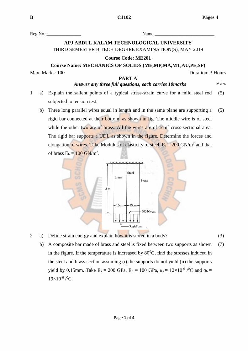
b) Three long parallel wires equal in length and in the same plane are supporting a
rigid bar connected at their bottom, as shown in fig. The middle wire is of steel
while the other two are of brass. All the wires are of 1cm2 cross-sectional area.
The rigid bar supports a UDL as shown in the figure. Determine the forces and
elongation of wires. Take Modulus of elasticity of steel, Es = 200 GN/m2 and that
of brass Eb = 100 GN/m2.
(5)
2 a) Define strain energy and explain how it is stored in a body? (3)
b) A composite bar made of brass and steel is fixed between two supports as shown
in the figure. If the temperature is increased by 800C, find the stresses induced in
the steel and brass section assuming (i) the supports do not yield (ii) the supports
yield by 0.15mm. Take Es = 200 GPa, Eb = 100 GPa, αs = 12×10-6 /0C and αb =
19×10-6 /0C.
(7)

B C1102 Pages 4
Page 2 of 4
3 A rectangular block of metal of 50mm×25mm cross-section and 125mm length
carries a tensile load of 100kN along its length, a compressive load of 1MN on
its 50mm×125mm faces and a tensile load of 400kN on its 25mm×125mm faces.
If E = 208GN/m2 and υ = 0.3, find (a) change in volume of bar (b) increase
required in 1MN load to produce no change in volume.
(10)
4 a) Define Torsional rigidity. (2)
b) A 3m long solid shaft transmits 15kW at 1200rpm. Find the required diameter of
the shaft, assuming that maximum shear stress in the shaft is limited to 25MPa
and angle of twist is not to exceed 50. Take G=80GPa.
(8)
PART B
Answer any three full questions, each carries 10marks
5 Draw the shear force and bending moment diagrams for a beam shown in the
figure given below. Also determine the value of maximum bending moment.
(10)
6 a) Define point of contraflexure. (2)
b) Draw the shear force and bending moment diagrams for a beam shown in the
figure given below. Locate the point of contraflexure.
(8)

B C1102 Pages 4
Page 3 of 4
7 a) Derive the equation of theory of pure bending. (6)
b) A rectangular section is to be cut from a circular log of wood of diameter
500mm. Find the dimensions of strongest section in bending
(4)
8 a) Derive an expression for determining shear stress distribution in a rectangular
cross-section of width ‘b’ and depth‘d’ and determine the maximum shear stress.
(4)
b) An I-section beam shown in the figure given below is subjected to a shear force
of 50kN. Draw the shear stress distribution diagram.
(6)
PART C
Answer any four full questions, each carries 10marks.
9 Two point loads of 5kN and 15kN are acting on a 5m simply supported beam at
1m and 2m respectively from the left end. Find the defections under the applied
loads. Also find the position and magnitude of maximum deflection.
(10)
10 a) Obtain an expression for maximum slope and deflection of a simply supported
beam subjected to a concentrated load ‘W’ at mid-span.
(6)
b) Differentiate plane stress and plane strain conditions giving examples. (4)
11 At a point in an elastic material under strain, there are normal stresses of 60MPa
(tensile) and 35MPa (compressive) respectively at right angles to each other with
a shearing stress of 25MPa. Find the principal stresses and position of principal
planes. Also find the maximum shear stress and its plane.
(10)
12 A member is subjected to stresses on two mutually perpendicular planes which
are 120MPa (tensile) and 60MPa (tensile). Shear stress across these planes is
30MPa. Find the principal stresses and maximum shear stress at a point by using
Mohr’s circle.
(10)
13 a) Derive expressions for equivalent bending moment and equivalent torque for a
shaft subjected to a bending moment ‘M’ and torque ‘T’.
(8)
B C1102 Pages 4
Page 4 of 4
b) What is meant by slenderness ratio? (2)
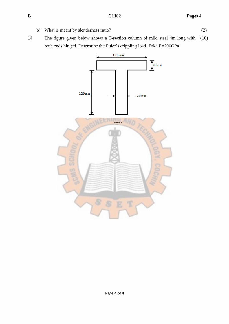
14 The figure given below shows a T-section column of mild steel 4m long with
both ends hinged. Determine the Euler’s crippling load. Take E=200GPa
(10)
****
B R3905 Pages: 2
Page 1 of 2
Reg No.:_______________ Name:__________________________
APJ ABDUL KALAM TECHNOLOGICAL UNIVERSITY
THIRD SEMESTER B.TECH DEGREE EXAMINATION, DECEMBER 2018
Course Code: ME201
Course Name: MECHANICS OF SOLIDS (ME,MP,MA,MT,AU,PE,SF)
Max. Marks: 100 Duration: 3 Hours PART A
Answer any three full questions, each carries 10 marks Marks
1 a) Derive an equation for deformation of a uniformly tapering circular rod
subjected to an axial load
( 5)
b) A rod of length 1.5 m and diameter 30 mm is centrally bored for 500 mm
length, the bore diameter being 10 mm. Under a load of 30 kN, if the extension
of rod is 0.2 mm, find the modulus of elasticity
( 5)
2 A brass rod 25 mm diameter is enclosed in a steel tube of 50 mm external
diameter and 25 mm internal diameter. The rod and tube are both initially 1.5 m
long and are rigidly fastened at both ends. Find the stress in two materials when
temperature rises from 300C to 1000C. Modulus of elasticity for steel and brass
are 200 kN/mm2 and 100 kN/mm2 respectively. Coefficient of thermal
expansion for steel =11.6 x 10⁻⁶/0C Coefficient of thermal expansion for brass =
18.7 x 10⁻⁶/0C
(10)
3 a) Find the modulus of rigidity & Bulk modulus of a circular rod of diameter
20 mm and length 2 m, if the longitudinal strain in the rod during a tensile
stress is four times the lateral strain. Take Modulus of Elas ticity = 2.1 x 10⁵
N/mm2
(5)
b) Draw the true stress-strain curve for a ductile material (5)
4 A composite shaft has an aluminium tube of external diameter 50 mm and
internal diameter 40 mm closely fitted to a steel rod of 40 mm. If the
permissible stress is 50 N/mm2 in aluminium and 120 N/mm2 in steel , find the
maximum torque carrying capacity of the compound bar.. Take Modulus of
rigidity for aluminium and steel as 27 x 103 N/mm2 and 80 x 103 N/mm2
respectively
(10)
PART B Answer any three full questions, each carries 10 marks
5 A simply supported beam of total span 10 m carries point loads of 20 kN & 40
kN at a distance of 1.5 m and 2.5 m respectively from left support. Also a
uniformly distributed load of 10 kN/m is acting over a length of 2 m starting
from left end. Draw the Shear Force and Bending moment Diagram
10)
6 a) Derive the relation between load, shear force and bending moment (5)
b) Draw the SF and BM diagram for a simply supported beam of total span 6 m
subjected to a clockwise bending moment of 24 kN-m at a point 4 m from left
support.
(5)
7 A simply supported beam of total span 8 m carries a central concentrated load (10)
B R3905 Pages: 2
Page 2 of 2
of 10 kN. The beam is of I-Section. The dimensions of I section are: top flange
200 mm x 50 mm, Web 200 mm x 50 mm, Bottom flange 130 mm x 50 mm.
Determine the maximum bending stress.
8 Draw the shear stress distribution diagram for an symmetrical I-section
subjected to shear force of 40 kN.The dimensions of I-section are : Top flange :
80 mm x 20 mm, web 200 mm x 20 mm , bottom flange 80 mm x 20 mm
(10)
PART C Answer any four full questions, each carries 10 marks.
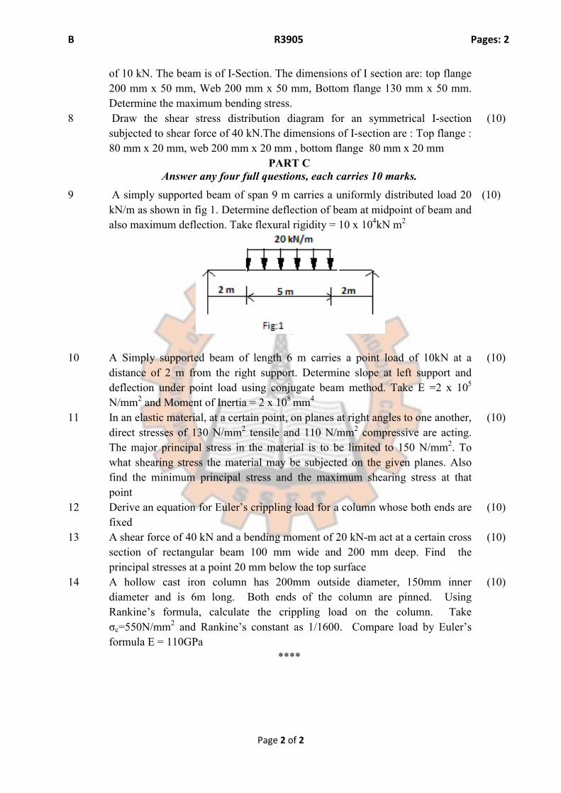
9 A simply supported beam of span 9 m carries a uniformly distributed load 20
kN/m as shown in fig 1. Determine deflection of beam at midpoint of beam and
also maximum deflection. Take flexural rigidity = 10 x 104kN m2
(10)
10 A Simply supported beam of length 6 m carries a point load of 10kN at a
distance of 2 m from the right support. Determine slope at left support and
deflection under point load using conjugate beam method. Take E =2 x 10⁵
N/mm2 and Moment of Inertia = 2 x 108 mm4
(10)
11 In an elastic material, at a certain point, on planes at right angles to one another,
direct stresses of 130 N/mm2 tensile and 110 N/mm2 compressive are acting.
The major principal stress in the material is to be limited to 150 N/mm2. To
what shearing stress the material may be subjected on the given planes. Also
find the minimum principal stress and the maximum shearing stress at that
point
(10)
12 Derive an equation for Euler’s crippling load for a column whose both ends are
fixed
(10)
13 A shear force of 40 kN and a bending moment of 20 kN-m act at a certain cross
section of rectangular beam 100 mm wide and 200 mm deep. Find the
principal stresses at a point 20 mm below the top surface
(10)
14 A hollow cast iron column has 200mm outside diameter, 150mm inner
diameter and is 6m long. Both ends of the column are pinned. Using
Rankine’s formula, calculate the crippling load on the column. Take
σc=550N/mm2 and Rankine’s constant as 1/1600. Compare load by Euler’s
formula E = 110GPa
(10)
****
B B3803 Pages: 2
Page 1 of 2
Reg No.:_______________ Name:__________________________
APJ ABDUL KALAM TECHNOLOGICAL UNIVERSITY
THIRD SEMESTER B.TECH DEGREE EXAMINATION, APRIL 2018
Course Code: ME201
Course Name: MECHANICS OF SOLIDS (ME,MP,MA,MT,AU,PE,SF)
Max. Marks: 100 Duration: 3 Hours
PART A
Answer any three full questions, each carries 10 marks Marks
1 a) A metallic bar 30mm diameter is subjected to an axial tensile load of 60kN. The
measured extension on gauge length of 150mm is 0.075mm and change in diameter is
0.00375mm. Calculate Poisson’s ratio, Young’s modulus and modulus of rigidity.
(6)
b) A rod which tapers uniformly from 50mm diameter to 30mm diameter in a length of
1.5m is subjected to an axial force of 150kN. Determine the elongation of the rod.
Take E = 200GPa.
(4)
2 a) State the principle of superposition. (2)
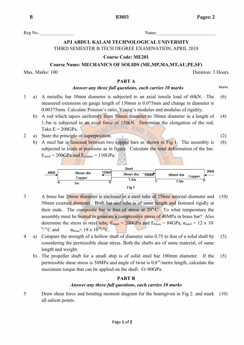
b) A steel bar is fastened between two copper bars as shown in Fig 1. The assembly is
subjected to loads at positions as in figure. Calculate the total deformation of the bar.
Esteel = 200GPa and Ecopper = 110GPa.
(8)
3 A brass bar 20mm diameter is enclosed in a steel tube of 25mm internal diameter and
50mm external diameter. Both bar and tube is of same length and fastened rigidly at
their ends. The composite bar is free of stress at 20°C. To what temperature the
assembly must be heated to generate a compressive stress of 48MPa in brass bar? Also
determine the stress in steel tube. Esteel = 200GPa and Ebrass = 84GPa, αsteel = 12 x 10-
6/°C and αbrass= 18 x 10-6/°C.
(10)
4 a) Compare the strength of a hollow shaft of diameter ratio 0.75 to that of a solid shaft by
considering the permissible shear stress. Both the shafts are of same material, of same
length and weight.
(5)
b) The propeller shaft for a small ship is of solid steel bar 100mm diameter. If the
permissible shear stress is 50MPa and angle of twist is 0.8°/metre length, calculate the
maximum torque that can be applied on the shaft. G=80GPa.
(5)
PART B
Answer any three full questions, each carries 10 marks
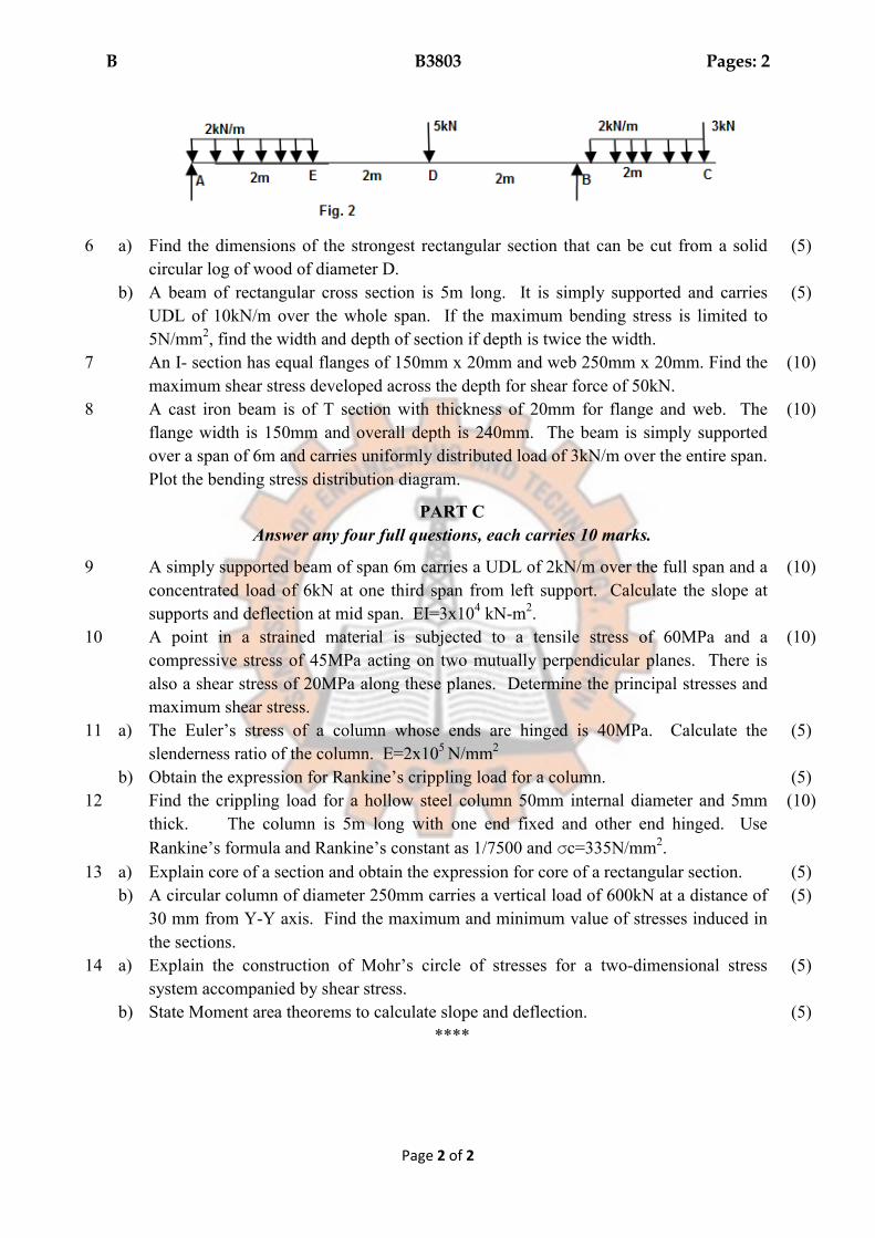
5 Draw shear force and bending moment diagram for the beamgiven in Fig 2. and mark
all salient points.
(10)
B B3803 Pages: 2
Page 2 of 2
6 a) Find the dimensions of the strongest rectangular section that can be cut from a solid
circular log of wood of diameter D.
(5)
b) A beam of rectangular cross section is 5m long. It is simply supported and carries
UDL of 10kN/m over the whole span. If the maximum bending stress is limited to
5N/mm2, find the width and depth of section if depth is twice the width.
(5)
7 An I- section has equal flanges of 150mm x 20mm and web 250mm x 20mm. Find the
maximum shear stress developed across the depth for shear force of 50kN.
(10)
8 A cast iron beam is of T section with thickness of 20mm for flange and web. The
flange width is 150mm and overall depth is 240mm. The beam is simply supported
over a span of 6m and carries uniformly distributed load of 3kN/m over the entire span.
Plot the bending stress distribution diagram.
(10)
PART C
Answer any four full questions, each carries 10 marks.
9 A simply supported beam of span 6m carries a UDL of 2kN/m over the full span and a
concentrated load of 6kN at one third span from left support. Calculate the slope at
supports and deflection at mid span. EI=3x10⁴ kN-m2.
(10)
10 A point in a strained material is subjected to a tensile stress of 60MPa and a
compressive stress of 45MPa acting on two mutually perpendicular planes. There is
also a shear stress of 20MPa along these planes. Determine the principal stresses and
maximum shear stress.
(10)
11 a) The Euler’s stress of a column whose ends are hinged is 40MPa. Calculate the
slenderness ratio of the column. E=2x10⁵ N/mm2
(5)
b) Obtain the expression for Rankine’s crippling load for a column. (5)
12 Find the crippling load for a hollow steel column 50mm internal diameter and 5mm
thick. The column is 5m long with one end fixed and other end hinged. Use
Rankine’s formula and Rankine’s constant as 1/7500 and σc=335N/mm2.
(10)
13 a) Explain core of a section and obtain the expression for core of a rectangular section. (5)
b) A circular column of diameter 250mm carries a vertical load of 600kN at a distance of
30 mm from Y-Y axis. Find the maximum and minimum value of stresses induced in
the sections.
(5)
14 a) Explain the construction of Mohr’s circle of stresses for a two-dimensional stress
system accompanied by shear stress.
(5)
b) State Moment area theorems to calculate slope and deflection. (5)
****
B B7075
Page 1 of 2
Total Pages: 2 Reg No.:_______________ Name:__________________________
APJ ABDUL KALAM TECHNOLOGICAL UNIVERSITY THIRD SEMESTER B.TECH DEGREE EXAMINATION, DECEMBER 2017
Course Code: ME201
Course Name: MECHANICS OF SOLIDS (ME,MP,MA,MT,AU,PE,SF)
Max. Marks: 100 Duration: 3 Hours PART A
Answer any three full questions, each carries 10marks. Marks
1 a) Explain Hooke’s law for linearly elastic isotropic material. (3) b) A steel tie rod 40 mm in diameter and 2 m long is subjected to a pull of 80kN. To
what length the bar should be bored centrally so that the total extension will increase by 20% for the same pull, the bore being 20 mm in diameter. Take E = 2 x 10⁵ N/mm2.
(7)
2 a) Define the terms resilience and proof resilience. (3) b) A copper strip 20 x 2.5 mm2 in section is held between two strips of steel each 20 x
2.5 mm2 in section. Find the stresses in steel and copper due to temperature rise of 6°C. Take αs = 1.2 x 10⁻⁵ / °C, αc = 1.85 x 10⁻⁵ / °C, Es = 2 x 10⁵ N/mm2 and Ec= 1.2 x 10⁵ N/mm2.
(7)
3 a) Define Poisson’s ratio. (2) b) A bar of circular cross section 20 mm diameter is subjected to an axial compressive
load of 100 kN. The increase in diameter is found to be 0.0082 mm. Calculate the values of Poisson’s ratio and modulus of elasticity. Take modulus of rigidity as 8 x 10⁴ N/mm2.
(8)
4 A solid aluminium shaft 1 m long and 50 mm diameter is to be replaced by a tubular steel shaft of the same length and the same outside diameter such that each of the two shafts could have the same angle of twist per unit torsional moment over the total length. What must the inner diameter of the tubular steel shaft be? Modulus of rigidity of the steel is three times that of aluminium.
(10)
PART B Answer any three full questions, each carries 10marks.
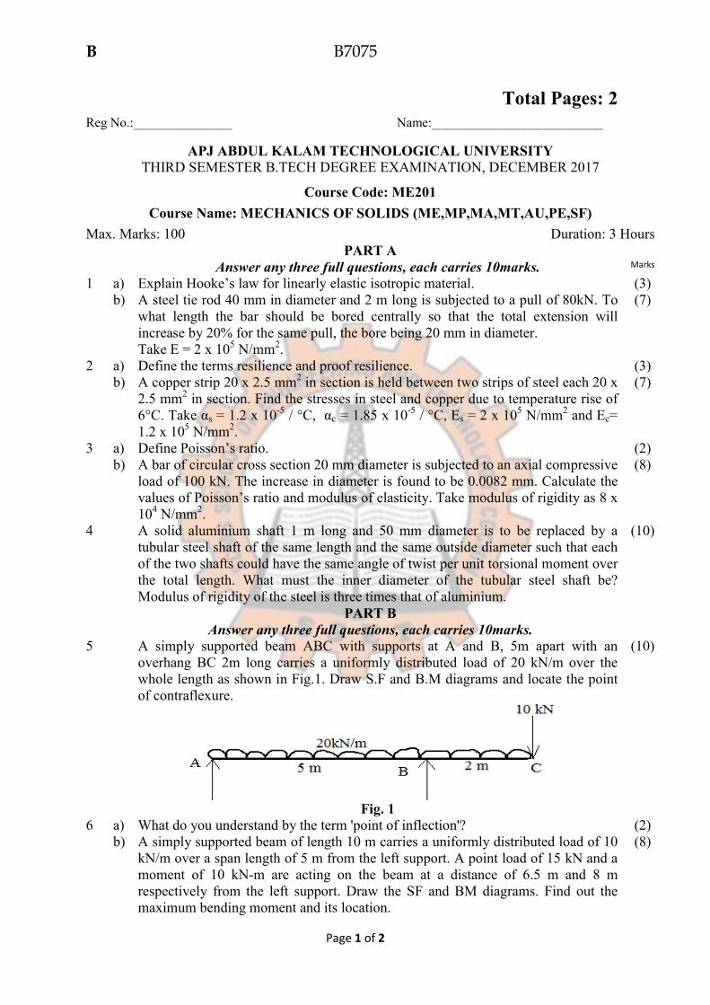
5 A simply supported beam ABC with supports at A and B, 5m apart with an overhang BC 2m long carries a uniformly distributed load of 20 kN/m over the whole length as shown in Fig.1. Draw S.F and B.M diagrams and locate the point of contraflexure.
Fig. 1
(10)
6 a) What do you understand by the term 'point of inflection'? (2) b) A simply supported beam of length 10 m carries a uniformly distributed load of 10
kN/m over a span length of 5 m from the left support. A point load of 15 kN and a moment of 10 kN-m are acting on the beam at a distance of 6.5 m and 8 m respectively from the left support. Draw the SF and BM diagrams. Find out the maximum bending moment and its location.
(8)
B B7075
Page 2 of 2
7 Derive from fundamentals pure bending equation
�
� =
�
� =
�
�. Also state the
important assumptions.
(10)
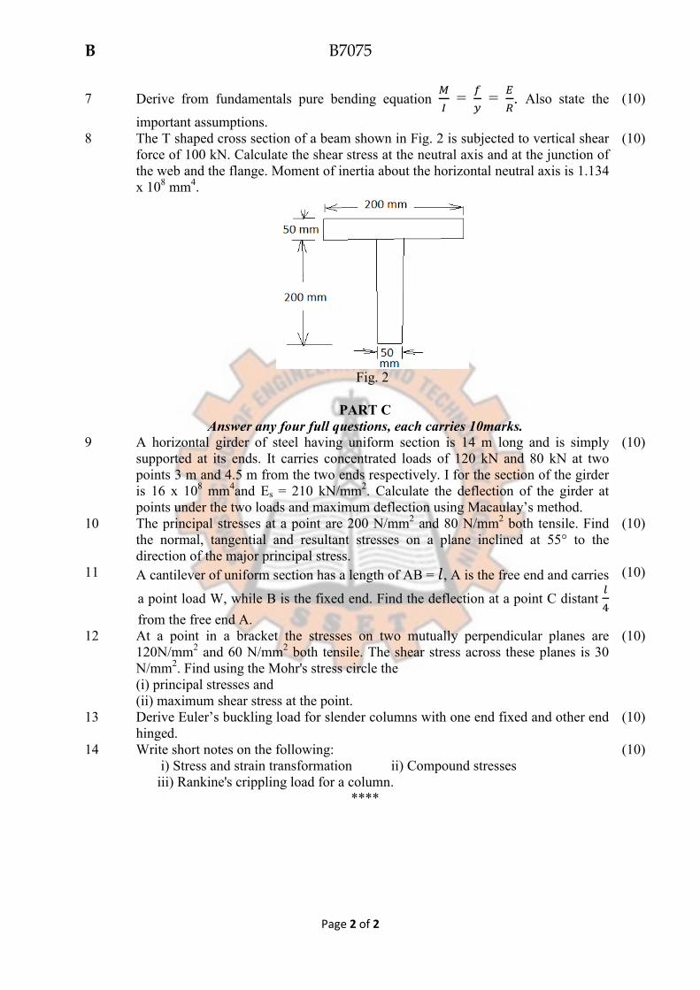
8 The T shaped cross section of a beam shown in Fig. 2 is subjected to vertical shear force of 100 kN. Calculate the shear stress at the neutral axis and at the junction of the web and the flange. Moment of inertia about the horizontal neutral axis is 1.134 x 108 mm4.
Fig. 2
(10)
PART C
Answer any four full questions, each carries 10marks. 9 A horizontal girder of steel having uniform section is 14 m long and is simply
supported at its ends. It carries concentrated loads of 120 kN and 80 kN at two points 3 m and 4.5 m from the two ends respectively. I for the section of the girder is 16 x 108 mm4and Es = 210 kN/mm2. Calculate the deflection of the girder at points under the two loads and maximum deflection using Macaulay’s method.
(10)
10 The principal stresses at a point are 200 N/mm2 and 80 N/mm2 both tensile. Find the normal, tangential and resultant stresses on a plane inclined at 55° to the direction of the major principal stress.
(10)
11 A cantilever of uniform section has a length of AB = �, A is the free end and carries
a point load W, while B is the fixed end. Find the deflection at a point C distant �
�
from the free end A.
(10)
12 At a point in a bracket the stresses on two mutually perpendicular planes are 120N/mm2 and 60 N/mm2 both tensile. The shear stress across these planes is 30 N/mm2. Find using the Mohr's stress circle the (i) principal stresses and (ii) maximum shear stress at the point.
(10)
13 Derive Euler’s buckling load for slender columns with one end fixed and other end hinged.
(10)
14 Write short notes on the following: i) Stress and strain transformation ii) Compound stresses iii) Rankine's crippling load for a column.
(10)
****
B B3B072S Pages: 3
Page 1 of 3
Reg. No._______________ Name:_______________________
APJ ABDUL KALAM TECHNOLOGICAL UNIVERSITY THIRD SEMESTER B.TECH DEGREE EXAMINATION JULY 2017
ME 201: MECHANICS OF SOLIDS
(AU, MA, MP, ME, MT, PE, SF)
Maximum Marks: 100 Duration: 3 Hours
PART A
Answer any three questions.
1. a. Write two points each on linear strain and shear strain? (4)
b. Two plates of thickness 2 mm each are joined using a single rivet. The plates are
subjected to a tensile load of 314 N. If the material of the rivet is having allowable shear
strength of 100 MPa, determine the diameter of the rivet pin? (6)
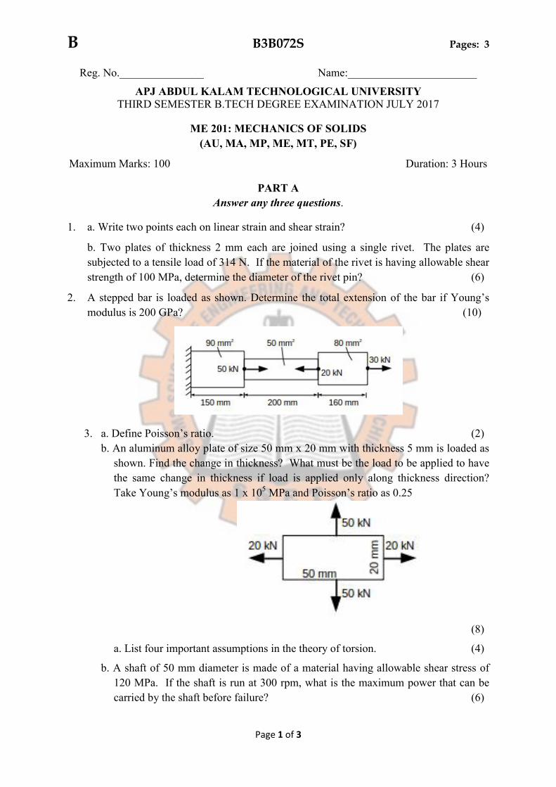
2. A stepped bar is loaded as shown. Determine the total extension of the bar if Young’s
modulus is 200 GPa? (10)
3. a. Define Poisson’s ratio. (2)
b. An aluminum alloy plate of size 50 mm x 20 mm with thickness 5 mm is loaded as
shown. Find the change in thickness? What must be the load to be applied to have
the same change in thickness if load is applied only along thickness direction?
Take Young’s modulus as 1 x 10⁵ MPa and Poisson’s ratio as 0.25
(8)
a. List four important assumptions in the theory of torsion. (4)
b. A shaft of 50 mm diameter is made of a material having allowable shear stress of
120 MPa. If the shaft is run at 300 rpm, what is the maximum power that can be
carried by the shaft before failure? (6)
B B3B072S Pages: 3
Page 2 of 3
PART B
Answer any three questions.
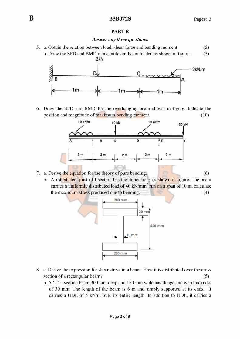
5. a. Obtain the relation between load, shear force and bending moment (5)
b. Draw the SFD and BMD of a cantilever beam loaded as shown in figure. (5)
6. Draw the SFD and BMD for the overhanging beam shown in figure. Indicate the
position and magnitude of maximum bending moment. (10)
7. a. Derive the equation for the theory of pure bending. (6)
b. A rolled steel joist of I section has the dimensions as shown in figure. The beam
carries a uniformly distributed load of 40 kN/mm2 run on a span of 10 m, calculate
the maximum stress produced due to bending. (4)
8. a. Derive the expression for shear stress in a beam. How it is distributed over the cross
section of a rectangular beam? (5)
b. A ‘T’ – section beam 300 mm deep and 150 mm wide has flange and web thickness
of 30 mm. The length of the beam is 6 m and simply supported at its ends. It
carries a UDL of 5 kN/m over its entire length. In addition to UDL, it carries a
B B3B072S Pages: 3
Page 3 of 3
concentrated load of 3 kN at its middle. Draw the shear stress distribution diagram
for the beam. (5)
PART – C
Answer any four full questions.
9. A horizontal girder of steel having uniform section is 14 m long and is simply
supported at its ends. It carries concentrated loads of 120 kN and 80 kN at two points
3 m and 4.5 m from the two ends respectively. I for the section of the girder is 16 x
108 mm4 and Es = 210 kN/mm2. Calculate the deflection of the girder at points under
the two loads. Find also the maximum deflection. (10)
10. A rectangular block of material is subjected to a tensile stress of 110 N/mm2 on one
plane and a tensile stress of 47 N/mm2 on a plane at right angles, together with shear
stresses of 63 N/mm2 on the same planes. Find:
(i) The direction of the principal planes. (3)
(ii) The magnitude of the principal stress (3)
(iii) The magnitude of the greatest shear stress. (4)
11. At a point in a bracket the stresses on two mutually perpendicular planes are 120
N/mm2 and 60 N/mm2 both tensile. The shear stress across these planes is 30 N/mm2.
Find using the Mohr's stress circle the
(i) Principal stresses and (5)
(ii) Maximum shear stress at the point. (5)
12. A round steel rod of diameter 15 mm and length 2 m is subjected to a gradually
increasing axial compressive load. Using Euler's formula find the buckling load. Find
also the maximum lateral deflection corresponding to the buckling condition. Both
ends of the rod may be taken as hinged. Take E = 2.1 x 10⁵ N/mm2 and the yield stress
of steel = 250 N/mm2. (10)
13. a. Derive Euler's formula for a column with one end is hinged and the other end fixed.
(5)
b. Derive the differential equation for deflection curve. (5)
14. a. What is the change in the support condition between actual beam and conjugate
beam? (3)
b. Define principal planes and principal stresses. (2)
c. Derive an expression for Rankine's crippling load for a column. (5)
*****
B B3B071 Total Pages:3
Page 1 of 3
Reg. No.___________ Name:______________________
APJ ABDUL KALAM TECHNOLOGICAL UNIVERSITY
THIRD SEMESTER B.TECH DEGREE EXAMINATION JANUARY 2017
ME 201: MECHANICS OF SOLIDS
(AU, MA, ME, MP, MT, PE, SF)
Maximum Marks: 100 Time : 3 Hours
PART – A
Answer any three questions.
1. a) Explain the stress-strain curve of a mild steel bar in tension test. (5)
b) A straight bar 450 mmlong is 40 mm in diameter for the first 250 mm length and 20
mm diameter for the remaining length. If the bar is subjected to an axial pull of 15 kN find
the maximum and minimum stresses produced in it and the total extension of the bar. Take E
= 2 × 10⁵ N/mm2. (5)
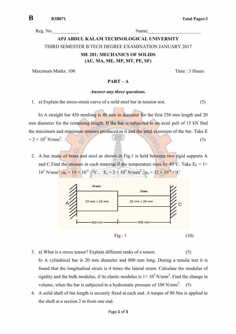
2. A bar made of brass and steel as shown in Fig.1 is held between two rigid supports A
and C.Find the stresses in each material if the temperature rises by 40°C. Take Eb = 1×
105 N/mm2 ;αb = 19 × 10-6 / °C , Es = 2 × 10⁵ N/mm2 ; αs = 12 × 10-6 / °C
Fig : 1 (10)
3. a) What is a stress tensor? Explain different ranks of a tensor. (5)
b) A cylindrical bar is 20 mm diameter and 800 mm long. During a tensile test it is
found that the longitudinal strain is 4 times the lateral strain. Calculate the modulus of
rigidity and the bulk modulus, if its elastic modulus is 1× 10⁵ N/mm2. Find the change in
volume, when the bar is subjected to a hydrostatic pressure of 100 N/mm2. (5)
4. A solid shaft of 6m length is securely fixed at each end. A torque of 80 Nm is applied to
the shaft at a section 2 m from one end.
B B3B071 Total Pages:3
Page 2 of 3
a) Find the fixing torques set up at the ends of the shaft. (4)
b) If the shaft is of 50 mm diameter, find the maximum shear stresses in the two
portions. (4)
c) Find the angle of twist for the section where the torque is applied. (2)
Take C = 105 N/mm2.
PART B
Answer any three questions
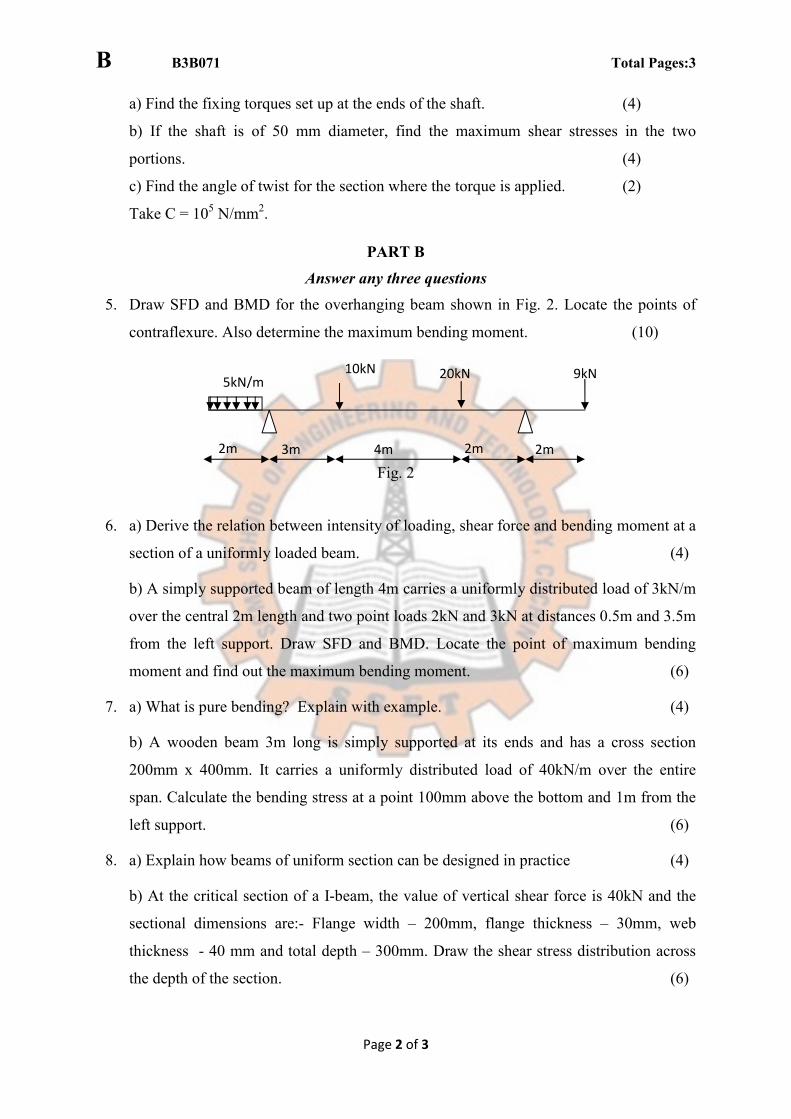
5. Draw SFD and BMD for the overhanging beam shown in Fig. 2. Locate the points of
contraflexure. Also determine the maximum bending moment. (10)
Fig. 2
6. a) Derive the relation between intensity of loading, shear force and bending moment at a
section of a uniformly loaded beam. (4)
b) A simply supported beam of length 4m carries a uniformly distributed load of 3kN/m
over the central 2m length and two point loads 2kN and 3kN at distances 0.5m and 3.5m
from the left support. Draw SFD and BMD. Locate the point of maximum bending
moment and find out the maximum bending moment. (6)
7. a) What is pure bending? Explain with example. (4)
b) A wooden beam 3m long is simply supported at its ends and has a cross section
200mm x 400mm. It carries a uniformly distributed load of 40kN/m over the entire
span. Calculate the bending stress at a point 100mm above the bottom and 1m from the
left support. (6)
8. a) Explain how beams of uniform section can be designed in practice (4)
b) At the critical section of a I-beam, the value of vertical shear force is 40kN and the
sectional dimensions are:- Flange width – 200mm, flange thickness – 30mm, web
thickness - 40 mm and total depth – 300mm. Draw the shear stress distribution across
the depth of the section. (6)
5kN/m 10kN 20kN 9kN
2m 3m 4m 2m 2m
B B3B071 Total Pages:3
Page 3 of 3
PART – C
Answer any four full questions.
9. A beam of length 6m is simply supported at its ends and carries two point loads of 48kN
and 40kN at a distance of 1m and 3m respectively from the left support. Find the
deflection under each load and the maximum deflection by Macaulay’s method. Given
E= 2x10⁵ N/mm2 and I= 85x106 mm4. (10)
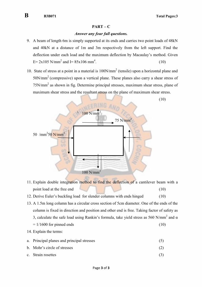
10. State of stress at a point in a material is 100N/mm2 (tensile) upon a horizontal plane and
50N/mm2 (compressive) upon a vertical plane. These planes also carry a shear stress of
75N/mm2 as shown in fig. Determine principal stresses, maximum shear stress, plane of
maximum shear stress and the resultant stress on the plane of maximum shear stress.
(10)
i. 100 N/mm2
75 N/mm2
50 /mm250 N/mm2
100 N/mm2
11. Explain double integration method to find the deflection of a cantilever beam with a
point load at the free end (10)
12. Derive Euler’s buckling load for slender columns with ends hinged (10)
13. A 1.5m long column has a circular cross section of 5cm diameter. One of the ends of the
column is fixed in direction and position and other end is free. Taking factor of safety as
3, calculate the safe load using Rankin’s formula, take yield stress as 560 N/mm2 and α
= 1/1600 for pinned ends (10)
14. Explain the terms:
a. Principal planes and principal stresses (5)
b. Mohr’s circle of stresses (2)
c. Strain rosettes (3)