b. as found tests - puc.hawaii.gov · 1.3 facilities and equipment for meter testing a. each gas...
TRANSCRIPT

b. As Found Tests
xl1 meters and/or associated metering devices shall be tested after they are removed from service. Such tests shall be rr,dde
before the meters and/or associated metering devices are adjuste repaired, or retired.
C. Leak Tests
Repaired meters, meters that have been removed from service,and nev meters shall be leak tested prior to installation. Each meter tested shall be subjected to an internal pressure of at Least 20“ ~J.C, and checked for the presence of leaks by one of the following tests:
1. Imeision test.
2. Soap test.
3. Pressure drop test of a type acceptable to the Commission.
d. tieter -Iesting on Request of'customer
1. Each gas utility shall at any time when requested by a customer upon not less than five (5) days' notice, test the accuracy of any meter in use by him.
No deposit or papent shall be required from the customer for such meter test except when a customer, whose average monthly bill for gas service is less than fifty (50) dollars requests a meter test within six months after date of the installation of said meter or six months after the last previous test, in which case he may be required by the utility to deposit with it, to cover the reasonable cost of such test, an amount not to exceed the following, unless specifically authorized by the Commission:
(a) For meters of rated capacities not exceeding 250 cubic feet per hour.................... $ 3.00
per meter (b) For meters of rated capacities exceeding
250 cubic feet per hour but not exceeding 400 cubic feet per hour.................... $ 5.00
per meter (c) For meters of rated capacities exceeding
400 cubic feet per hour but not exceeding 4,000 cubic feet per hour.................. $10.00
per meter
(d) Fees for tests of meters of greater rated capacity than 4,000 cubic feei per hour or for testing meters under extraordinary conditions will be furnished upon application to the Commission.
-21-

--
Tne amount depositied with the utility shall be refunded to the customer if the meter is found to register more than two (2) per cent over or under the prover registration.
2. A customer shall have the right to require the utility to conduct the test on his meter in his presence, or if he so desires, in the presence cf an expert or other representative appointed by him.
3. A report giving the name of the customer requesting the test, she date of the request, the lccation of the premises where she meter was installed, the meter reading at time of removal, the date tested, and the result of the test, the type, n2ke , size and number of the meter, the date of remcva! and deductions dr?wn therefrom shall be supplied to such custosl~!t~vrthin-a-rea'sbcabfe-tL~e.aft~r the-.completion of the test and a duplicate of such report shall be filed with the Cmission.
8. Periodic Tests
Unless cthervise authorized by the Commission each utility shall make periodic tests of meters, associated devices and instruments, to assure their accuracy. Such tests shall be scheduled within the caiendar year, or earlier, when the interval is stated in years; or within the calendar month, or earlier, when the interval is stated in mcnths. The basic periodic test interval shall not be lcnger than provided for in the following schedule: (Note: Eaiatenance programs suggested by manufacturers of the following me rer 3 and devices should be carefully followed.)
* t. fosttive displacement meters
(3) Up to 250 c.f./hr. (except meters on space heating installations)
(b) 250 to 1500 c.f./hr.
(c) Up to i500 c.f./hr. on space heating installations
(d) Over 1500 c.f./hr.
2. Orifice meters
3. Base pressure correcting devices
4. Base volume correcting devices
2. Secondary standards
<a> 12s~ bottles, one cubic fact
(5) Eead weight testers -22-
10 years
7 years
7 years
2 years
6 months
24 months
24 months
10 years
10 years

6. Working standards
(a) Bell provers 3 years
(b) Rotary displacement test meters 5 years
Cc> Fl ow provers 5 years
(d) Laboratory quality indicating pressure gauges 6 months
7. If found inaccurate, each such meter shall, at the time of each test, be readjusted to be correct within the prescribed limits before again being installed.
8. If, during an inspection or the servicing of appliances or equipment on a customer's premises, a meter is observed to be in such a condition or so operating as to cause doubt of its accuracy or establish as a certainty that it is not recording within the limits of accuracy prescribed by these rules, it should be removed immediately without alteration of its condition, and tested, provided that in cases where removal is not feasible, same should be tested in place.
6.2 Test Procedures and Accuracies
Meters and/or associated metering devices shall be tested at the points and adjusted to the tolerances prescribed below. The test of any unit of metering equipment shall consist of a comparison of its accuracy with the accuracy of a standard. The Commission will use the appLicable provisions of the standards listed in Rule 5.2 as criteria of accepted good practice in testing meters.
a. Positive Displacement Meters
1. Accuracy at test points
Flow Adjusted to within
Check flow + 1% or - 2%
Not less than full rated flow + '1% or - 2%
2. Overall accuracy
The accuracy at check flow and the accuracy at not less than full rated flow shall agree within one percent.
b. Orifice Heters
Accuracy at test points must be within f 2%.
-23-

C. Timing Devices
All recording type.meters or associated'instruments-which have a timing elemeqt that servei to record the t.ime at which the measurement occurs must be adjusted so that the thing element is not in error. by more than plus or.minus '4 minutes in 24 hours.
d. General
1. All meters,and/or associated metering devices, when tested, shall be adjusted as closely .as practicable to the condition of zero error.
2. All tolerances are to be interpreted as maximum permissible variations from the condition of zero error: In making adjustments no advantages of the prkcribed tolerance limits shall be taken.
1.3 Facilities and Equipment for Meter Testing
a. Each gas utility shall, unless otherwise specifically required by these rules, provide such laboratory equipment, meter testing equipinent, and other testing facilities for each gas manufacturing or. mixing plant, meter repair shop or testing station, as may be necessary to.make the tests required of it by.these rules or other orders of the Commis&ion. The apparatus and equipment so provided shall be of a type and form approved by the.Ccnmnission, and it shal be available at all times for the inspection or. use of any authorize representative of the Commission..
b. Each gas utility shall make such tests as are prescribed under these rules with such frequency and in such.manner, and at such places as herein provided, or as may be approved or ordered by the Commission.
C. Each gas utility shall file with the Commission a detailed state- .ment showing the location of each laboratory, meter testing shop
and testing station owned, controlled or operated by the utility, together with a full and complete description of each major testing or standardizing instrument- or apparatus maintained therein Any major change or addition to testing instruments and apparatus, or abandonment of testing instruments or apparatus shall be reported to the Commission within ten days after the change has become effective.
d. The area within the meter shT used for the testing of meters shall be designed so that the meters and meter testing equipment are protected from drafts and excessive changes of temperature.
1. The.meters to be tested shall be stored in such manner that the temperature of the meters is substanttally the same as the tanperature 'of the.prover.
-24-

e. W~rki~.g Standards
1. Each utility shall own and maintain, or have access to, at least cne approved bell type prover of 5 cubic foot capacit! and aL1 other equipment necessary to test meters, which shal be installed in the meter room.
(a) Pfeans shall be provided to maintain the temperature of the liquid in the meter prover at substantially the sami level as the ambient temperature in the prover room.
(I?) The meter prover shall be maintained in good condition 2 correct adjustment so that it shall be capable of deter- mining the accuracy of 3ny service meter to within one- haLE of one percent.
2. Each utility having meters which are too large for testing c a 5 cubic foot bell prover may CIS~ a properly calibrated tez meter or a properly designed flow prover for testing the large meters.
t. Workins standards must be checked pericdically (see Rule 6.le) * by comparison with a secondary standard.
I.. Eel1 provers must be checked with a I cubic foot bottle which has been calibrated by the sational Bureau of Standards.
7 -. Rotary displacement test meters must be checked with a btli prover of adequate capacity which has been calibrated by representatives of the National Bureau of Standards.
&* Extrne care must be exercised in the use and handling of standards to assure that their accuracy is net disturbed.
h . Each standard shall be accompanied at all times by a certificate or calibration card, duly signed and dated, on which are recordel the corrections required to compensate for errors found at the custorr.ary test points at the .tipe of the Last previous test.
1. Each utility must have properly calibrated orifices, as may be necessary, to achieve the rates of flow required to test the meters on its system.
Records of Ptetcrs and Associated Metering Devices
Each utility shall maintain records of the following data, where applicable, for each meter and/or associated metering device unti retirement:
a. The complete identification--manufacturer, nmber, type, capacit! miiltiplicr, constants, and pressure rating.
b. The da:es of purchase, installation and removal from service, toge t!-.cr with the Location.
-2J-
.d

k:eter Test Records
Each utility shall maintain records of at least the last two tests made of any meter. Tne record of the meter test made at the time of the meter’s re’tirement shall be maintained for a minimum of 3 years. Test records shall include the following:
a. Tne date and reason for the test.
I?. The reading of the meter before making any test.
C, The accuracy “as found” at check and full rated flow.
d. Tz.e accuracy “3s left” at check artd full rated flow.
e. In the event test of the meter is made by using a standard meter cr a flow prover, th.e utility sb.311 retain all data taicen at the time of the test in sufficiently complete form to permit the convenient checking of the test methods and the calculations.
FART VII STANlARDS OF QUALITY OF SERVICE
Purity Requirements
AL1 s-35 sapplied to custners shall be substantially free of impuriti which may cause corrcsicn oE mains or piping or form corrosive or h.armf*Jl. fumes when burned in a properly designed and adjusted burner.
3. Kydrc gen su Lphide
No gas supplied by any 83s utility for domestic or commercial purposes in this State shall contain mere than a trace of hydroge sulphide. The gas shall be considered not to contain more than a trace of hydrogen sulphide if 3 strip of white filter paper moistened with a solution containing S per cent by weight of lead acetate is not distin.ctly darker than a second paper freshly mcistened with the same solution after the first paper has been expcsed to the gas for one minute in an apparatus of approved fcrm through which the gas is flowing at rate oE approximately five cubic feet per hour, the gas not impinging directly from 3 jet upon the test p3per.
b. Total S*LL@xur and Amonia
iSo gas supplied by any ga s utility for domestic or commercial purposes shsll contain more than thirty (30) grains of total su Lphrr r , and more than five (5) grains of ammonia in each one hundred (100) c*lbic feet .
-25-

1
C. Test of Gas Purity
Each gas utility supplying manufactured gas for domestic, commercial or industrial purposes shall make daily tests of the gas leaving its manufacturing or purifying plants for the presence of hydrogen sulphide in the manner above specified. Each gas manufacturing or purifying plant having an annual output in excess of one hundred million (100,000,000) cubic feet of gas shall be equipped with, and shall maintain, such apparatus and facilities as are necessary for the determi- nation of total sulphur and ammonia in gas; and each utility operation such as a plant shall make tests weekly or oftener as may be found necessary, and keep a continuous chronological record of the amount of total sulphur and ammonia in the gas distributed by it. In Lieu of testing the sulphur content of the manufactured gas, Utilities supplying oil gas may make sulphur content tests of the oil stock by bomb calorimeter test. Sulphur content of the oil shall be determined when base stocks are known to be changed at two week intervals, provided the sulphur content of the oil does not exceed L.5%. For oil stock with sulphur content in excess of L.S% the manufac- tured gas shall be tested at least weekly as provided above. The records herein provided shall be kept at the station where made, provided, however, that such a utility suppLying only water gas or oiL gas shall not be required to provide apparatus for or make determinations of the amount of ammonia in gas.
d. In the case of those utilities supplyin g a mixed gas these standard sj of gas purity shall apply to the manufactured gas prior to mizttlre, excepting in emergencies or in special cases, by approval of the Commission.
Pressure Limits
a. Standard Gas Delivery Pressure
L. Each gas utility supplying gas for domestic or commerciaL purposes shall, subject tc the approval of the Commission, adopt and maintain a standard pressure of gas as measured at the outlet of any customerls meter. In adopting such a standard pressure, each utility may divide its distri- buting system into districts and establish a separate standard pressure for each district, or the utiLity may establish a single standard pressure for its distributing system as a whole.
2. The Standard Pressure adopted as herein provided shaLL be filed with the Comission 3s a part of each gas utility's schedule of rates, rules and regulations, and shall be
-2J-

.
i
i clearly set forth ir. the schedules of rates, rules ar?d 1
.r~gulatioas of the utility kept 3po-n to the pnblic i
itiS?ection at each office cr location where 3?plCcations x0, - =- service are received.
3. -. x0 ckang e shall be -,ade in the stacd3id pressure adopted by if for any diJ -trict or rystm without the approval cf the Corzzis - sim.
b . ?-5iin-kca and A,aximzz Gas Pressure
Ihe pressure of gas supplied at low pressure to daestic and cmercial custczers shall ilot vary S?sre than fifty per cent (50X above or belc-d th& standard pressure -&i.ch the utility has : adopted fer 3 district cr system, as herein provided, and CO such vaiiatio; in pressure sh311 be =oie than th3t equivalent to four is&es of water cc1um-t above cr below the stendard. sic v3riaticn in pressure from the stazd3rd pressure of two inches or Eoie of water ccl-mm shall occur iz a shorter tiiae th3;‘ fifteen (15) ninuies excepting ZZeRt3iy fluctuations 02
individual services caused by the oper'%iiocs of custmer's a;;pliacces or flcctcatiocs caused by i23scndbl2 regulator buildup
7.3 tiessure Surveys and Reccrds
a. Each utiity shall z3ke a sufficient nmber of pressure seas- urezents on its aains acd at the custozer's meter so that it will have a substantially accurate. kcowledge of the pressures in the low, intemediate and high pressure systms in each districi, division, or c-unity served by its distribution iraics.
be All. pressure records obtained under RJle 7.3 shall be retaiRed by the utility for at leas! 2 years azd shall be available for impection by the Cosziss-fcn's representatives. Xotations on each record sh3ll ir?dicate the followicg:
1. The location where the pressure check was zade.
2. The t&e and date cf the check.
-2<3-

I 7.G Standards For Pressure Measurements I
a. Secondary Standards
Each utility shall own or have access to a dead weight tester. This ins‘trument must be maintained in an accurate condition.
b. Working Standards I
Each utility must have water manometers, mercury manometers, laboratory quality indicating pressure gauges and field type dead weight pressure gauges as necessary for the proper testing of the indicating and recording pressure gauges used in determining the pressure on the utility's system.
C. Working standards must be checked periodically (see Rule 6.2 e) by comparison with a secondary standard.
d. Extreme care must be exercised in the handling of standards to assure that their accuracy is not disturbed.
e. Each standard shall be accompanied at all times by a cer- tificate or calibration card, duly signed and dated, on which are recorded the corrections required to compensate for errors found at the customary test points at the time of the last previous test.
f. Low-Pressure Distribution Systems I
1. Each gas utility shall own and maintain at least one recording pressure. gauge on each principal distribution main leaving each gas manufacturing plant, compressor, or holder station and no utility shall maintain less than two such gauges unless specifically relieved in writing by the Cv7mnission. Pressure charts taken from such gauges shall be preserved as a continuou record for a period of at least two years.
2. Each gas utility shall own and maintain at least one low pressu portable recording pressure gauge for each one hundred (100) miles or fraction thereof of low pressure main in any district as may be ruled a separate distributing system by the Commissio i
I 3. On Sow pressure distribution systems each gas utility shall
during the six months of the peak season of the year make at least one twenty-four-hour record of pressure each week at the outlet of customer's meters for each one hundred (100) miles or less of tiistr'ibution main in each district or separate distributing system. Such record shall bear the address of the customer where the pressure is taken and the dates, together with such other information as the Commission may from time to time direct and shall be filed and retained as a continuous
-29-
2,

r I
I
record for a period of at 123st two calendar years in the pil-c*;-L 'n--i;lrJ? office .cf each district or division. Is lieu of fifty per cent (507.) of the above reti_uirtJ number of recor2~ frm portable 2resSure gs~&- 7-g ar: custszEris pre~icss there may be Substituted an equal number cf %&23+y*ffLlr (24J _ , hour records from recorJLng pressure gauges t,;rm.inently located at crftical points on the distribctien sy~tsa.
g. fiigh-Fressure Distributicn Eystems
1. On hfgh'prersure distribution systems, gas'utilities shall maintain permanently located -pressure gauges at critical pckts to msesure the pressures on both aides of the -pressure regui2tor2. &ca&iag SiesSuie gaszges shall *De ~~e.~ ~~ h1g.h . 37% 2 en?.? I -%&.I-- distribution Systems with over SGO cuszcmers, In S-fS i2p.s of s?T?&r 500 fsstm:rs, 2 fq cf '3rc'ssuI'2 3"'<. i?ZldiZgS Jhtil ‘ES? ~aic+-si~ed with g"~~e% read WE2ki)' aed uoon dciivsry into 'I-KG holder stations. Charts from thsse gauges and the log of pressure geuge readings shall b+ QresE?rvfd in the district or division offices as a ccn- tinuous record for a period Gf at least tiJo (2) years.
Pressure conditions 01: the customer's premises on high pressure distribution Systems Shall be determined by water coluzlr test% made,dc~irg Service calls Ifi answer to ccnplairts. A i2QOrt LX Such tests Shall be nade on th;c- complaint aider, which report shall state the pressure observed when sp?liances were on and when all a?pii;nces (excepting silct lights) were I cff, and it Shall state whether the test tias made tit the out- let of the meter or at the customer's appliance. Fresjure tests shall be made on one hundred per cent (100X) 2f the pressure cmslaints received.
i-5 fieating Value
Heating Value Standard for Manufactured and Piked Gas
1. Each gas utility supplying manufactured cr nixed gas for domestic, commercial. or industrial pspses, either directly or through a second utility, Shall establish and mintain, with the approval of the Commission, a Standard heating value for its product. The monthly average heating value of the gas measured in the manner and place as hereinafter provided shall meet the requirements df the standard established.
2. Each gas utility Supplying manufactured oi nixed gas shall file with the Commission a3 a part of its schedule of rates, rules and regulations, a statement cf the Standard heating value cf the gas Supplied by it:

(a). At the outlet of its p1ar.t at low pressure delivery.
(b). TO its customers in each district as may be ruled a separate distribution system by the Coxrmission.
A similar statement shall be inserted in its schedule of rates, rules and regulations, kept open to public inspection at each, office or location where applications for service are received.
'0 . Daily Variation in Heating Value of Manufactured and Mixed Gas
The maximum variation of the heating value of manufactured or mixed gas leaving the plant shall be filed with the Commission.
C. iieating Value. of Hydrocarbon Gas
Each gas utility supplying hydrocarbon gas for domestic, commercial or industrial purposes shall file with the Conmission as a part of its schedule of rates, rules and regulations, the average total heating value of the hydrocarbon gas, together with the maximum fluctuation above and below the average total heating value which may be expected cf the gas supplied by it in each district, division or community served.
d. Monthly Average Heating Value
1. Ihe monthly average total heating value of manufactured or mixed gas at any given test station s.hall be an average of the daily determination as provided for in Rule 7.6.
2. The monthly average total heating value of hydrocarbon gas at any given test station shall be an average of all total heating value tests made during each month in fulfillment of the requirements of Rule 7.6.
7.6 Heating Value Determination and Reccrds
a. Heating value tests shall conform to Chapter II "STANDARDS OF CALORIMETRY FOR GASEOUS FUELS" adopted by this Commission con- tained herein.,
b: Calorimeter Equipment
1. Each gas utility supplying manufactured or mixed gas shall provide and maintain'testing stations equipped with a calori- meter complete with all necessary accessortes thereto, and of a type approved by the Commission, as follows:
(a) One testing station at each gas manufacturing or mixing plant supplying each district, division or community, provided that such testing station may be installed at a point near the center of distribution, subject to the approval cf the Commission. -. -
-3l-

ib) A gas xtility distributing in any district: division or community manufactured or mixed gas purchased from a second utility shall be conscdered a manufactured or mixed gas utility and shall install testing stations in accordance with these rules.
2. A gas utility supplying any district, divisicn or community with hydrocarbon gas, in which the annual sales exceed one hundred million (100,000,000) cubic feet, shall establish a testing station,' or take samples indicative of the supplied gas, and shall make at least one determination per week of the total heating value of the gas delivered to customers.
C. Heating Value Tests
1. Manufactured or Mixed Gas
(a> Each utility supplying manufactured or mixed gas and maintaining a testing.station at the manufacturing or mixing plant shall determine daily the heating value of the gas leaving the plant. .This determination shall be as near a weighted average quality of gas sent out each day as practical limitations will permit, obtained either by averaging a series of tests taken at intervals in a manner approved by the Commission or by a test made upon a continuous sample taken and held by a device approved by the Commission.
(b) Each utility supplying manufactured or mixed gas and maintaining a testing station near the center of the distribution sb211 determine the heating value of the gas being delivered on at least six days per week in the manner prescribed above.
(c) Each gas utility supplying manufactured or mixed gas and maintaining a testing station shall determine the heating value of the gas.in the mains at the,outlet of each manufacturing or mixing plant at least three times each day, at intervals of not less than three and one- half (s) hours, unless in the opinion of the Commission more frequent determination shall be made in which event determinations shall be made in the manner and at such times as may be approved by the Commission.
2. Hanufactured or Mixed Gas Affected by Compression or Other Processes.
Each utility supplying manufactured or mixed gas, the operations of which involve compression or other processes affecting the heat content of all or any portion of its gas after the gas has been delivered from the manufacturing or mixing plant, shall maintain such equipment and make such tests as may be prescribed by the Commission.
-32-

7
3. Hydrocarbon Gas
Each gas utility supplyin, 0 hydrocarbon gas for domestic, commer- cial or industrial purposes shall make tests of the gas delivere to its customers at such locations and with such frequency .as ma be prescribed by the Commission and shall keep a permanent chron logical record of all tests of total heating value received or delivered to it; provided, that if heating value determinations of the same gas are satisfactorily made by an approved testing Laboratory or another utility these determinations may be used for the purpose of the above record upon written approval of the Commission. In cases where unmixed hydrocarbon gas is served, the heating value may be calculated upon the basis of analysis of the shipment as received by the utility from the producer or manufacturer.
d. Heating Value Test Records
Each gas utility making heating value determinations as herein provided shall adopt, subject to the approval of the Commission, a standard form for recording the data and results of each such test.‘ Each determination of heating value shall be recorded upon the form adopted for that purpose and such forms shall be retained as a chronological record at the station where made for a period of not less than two years.
Interruptions of Service
Any gas utility contemplating an interruption to service on its entire system or in any major district thereof shall first submit its plan to the Commission for approval.
a. Each gas utility shall keep a record of all interruptions to service on its entire system, or in major divisions or operating districts thereof, including a statement of the time, duration and cause, if known, of the inerruption. Any such interruption of over one (1) hour shall be reported to the Commission as soon as possible after its occurrence. Such records should include the following information concerning the interruptior
1. Cause
2. Date and time
3. Duration
b. Planned interruptions shall be made at a time that will not cause unreasonable inconvenience to customers and shall be preceded by adequate notice to those who will be affected.
-33-
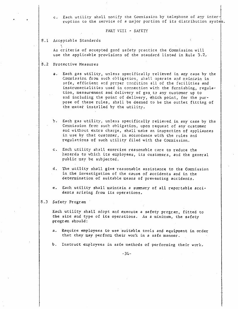
C. Each utility shall notify the Cmission by telephone of an_y inter-/ ruption to the service of a roajor portion of its dixribution systc
PART VIII - SXEE
Acceptable Standards t I
us criteria of accepted good safety practice the Comission will use the applicable provision s of the standard listed in Rule 5.2,
Frotective Pleasures
a. Each gas utility, unless specifically relieved in any case by the t~~i-isaic;, - -Lb:' f-T fiich c-2Ligatioz. s'I.3 11 oper3te a2d ;r.air.tain in safe, efficient acd prc?er cocdition aLL of the facilities and ip-strEe?Caiities cse$ irt cor?necticn with the furnishing, regula- tion, measurezeet and delivery of gas-to a2y custmer up to sod including the pain: of delivery, *hi&. point, for the pur- pose of these rules, shaLL be deeied to be the outlet fitting of the zeter installed by the utiiity.
5. Each ,531 utility, unless specifically relieved. in any ca6e by .the tozcissioh froic .s~ch obiigatioa, upon request of any custoicer 322 nithoct estra charge, shafi. 13ke an insgecticn of appliances in use by that cust=ei, in accordance with the rules and regulations of such utility fiLed with the Cmission.
C. Each uti?ity shall exercise reasonable care to reduce the ;?azards to wki.cY* -. __ its employees, its custmers, and the general pubLic nay be s..bjected.
d. The utility shall give reasonable assistance to the Coitzission in the investigation of the cause of accidents and in the determination of suitable ne3r.s of preventicg accidents.
e. Each utiLity shall tzaintain a summary of all reportable acci- dents arising fim its ooerations.
Safety Program
Each utility shail adopt and execute a safety prcgra, fitted to the size azd type of its operations. As a mink-m, the safety progzzx should:
a. Require ezpLcyees to use suitable tcols and equip-,ent in order that they zay perform their woi!< in a safe manner.
b. Icstruct espLcyees in safe methcd s of perforieing their work.
--Jr;-

C. Instruct employees who, in the course of their work are sub- ject to the hazard of electrical shock, asphyxiation or drown- ing, in accepted methods of artificial respiration.
8.4 Customers Piping
Each customer's piping system shall be tested for service is turned on.
a. Pressure Test
leaks before
If local authorities do not require a pressure test of customer's piping, as set forth in American Standard Installation of Gas Appliances and Gas Piping, ASA 221.30, the utility shall ad- vise the customer of the desirability of having his plumber conduct such a test.
b. Leakage Test
Before permitting the use of gas at any location, the piping system shall be tested for Leaks by a method at least equal to &hat described in Section "Leakage Check After Gas Turn On," in the latest edition of the American Standard Installa- tion of Gas Appliances and Gas Piping, ASA Z21.30.
.. c . Service Cocks
On and after the effective date of this order each and every gas service line installed or reconstructed shall include a suitable shut-off valve, or cock, properly housed or encased so as to be accessibLe at all times, located cutside of the structure served and between said structure and the gas main from which said service is supplied.
9.5 Gas Leaks
A report of a gas Leak shall be considered as an emergency re- quiring immediate attention.
3.6 Odorization
Any gas, distributed to customers through gas mains or gas services or used for domestic purposes in compressor plants, which does not naturally pos+ss a distinctive odor to the extent that its presence in the atmosphere is readily detectable at all gas concentrations of one-fifth of the lower explosive limit and above, shall have an odorant added to it to make it so detectable. Odorita- tion is not necessary, however, for such gas as is delivered for further processing or use where the odorant would serve no useful purpose as a warning agent. Suitable tests must be made to determine Ghether the odor meets the aforementioned standards.
-35-

c .
STXiDARDS OF CALORIMETRY FOR C-1ISEOV.S FtiELS -
L,L AFpLicabiLity cf Rules
men a change is desired in the type of czilcrixeter to be u& ar_ a 9.;" calorimeter station, a request shall be made to the Commission by the L&my, briefly stating the authorization sought, the type of.caLori- meter presently being used at the calorimeter smtion, the type of calo- rimeter desired to be used at the station in the future, and the major reas3r;. for makin tke change.
l,Z Ceviaticxs from Rules
In no case shall any public utility deviate from the methods herein set forth except with speciaL written authorization from the Commission. If hardship results from the application of any rule herein-prescribed because of special conditions, application may be made to the Ccmmissti for authorization to deviate therefrom. S~:c?~request for deviation authority shall set forth a complete justification of the proposed pro- cedure.
1.3 Definitions
a. Fuel Gas
Any conbustible gas or vapor, or combustible mixture of gaseous ccnstituents, used to produce heat by burning.
b. FueL Gas Calorimeter
An apparatus for determining the calorific (heating) values of fuel gases.
1. Recording Calorimeter
An automatic device that continuously makes a written record of the heating value of a fuel gas or mixture of fueL gases on a chart.
2. Water-Flow Calorimeter
A laboratory device for measuring the total and/or net heating value of a fuel gas or mixture of fuel gas&s in which the heat evolved by the complete combustion of a measured quantity of gas burning at a uniform rage is absorbed by a quantity of water aIS0 flowing at B-uniform rate. The tieight and increase in temperature of the water flowing during the interval that the measured quantity of gas is being b-rned furnish the prim&? data necessary for caLcuLating the heating value of the gas.
-36-

c. CaLorinet2r Station
The location at which a calorimeter is maintained for the purpose of in2 value of a fuel gas. determining the heat
S:andard Temperature
60 ’ F., based on the
Standard Pres6ure
international temperatura scale.
The absoluteopressure of a column of pure mercury 30 inches in height at .3 (980.665 cm se?) 3
and under standard gravity (32.174 f t ./sec2) or
Standard Cubic Foot of Gas
The quantity of gas which, when saturated with water vapor and at a temperature of 60’ F. and under a pressure of 30 inches in height of mercury at 32O F. (density 13.5951 grams/cc and acceleration of gravity 980.665 crds2c2) occupies one cubic foot.
Dry Cubic Fbot of Gas
Th2 quantity of gas which, when free of water vapor at standard temperature and under standard pressure will fill a spa,ce of one cubic foot. The total heating value of one dry ‘cubic foot of gas is equal to the product of the total calorific value per standard cubic foot and the constant 1.0177.
British Thermal. Unit (Btu)
The quantity of heat that must be added to on2 avoirdupois pound
of pure water to raise its tem?erat,ure from j8.5p F. to 59.5” F. under pressure.
Total Calorific Value
The nu_nber of British thermal units evolved by the complete combustion at constant press&e, of one standard ccibic Eoot of gas witti air, the temperature of the gas, air and products of combustion being 60° F. and all of the water formed by the combustion reaction being condensed to the liquid state.
Net Calorific Value
The number of British thermal units evolved by the complete combustion at cdns tant pressure, of one standard cubic foot of gas with air, the t2mperature of the gas, air and products of combustion being 60’ F. and all of the water formed by the combustion reac:ion remaining in
-37-

the vapcr state. The net calorific value of a gas is its total calorific value minus the latent heat of vaporization at standard temperature of the uater fcrmed by &he combustion react idn. La tent heat cf vaporization of water at 500 F. = 1057.8 Btu per lb. or 50.37 Btu per standard cubic foot.
Theoretica I Air
The vcl&Te of air that contains the quantity of oxygen, in addition to that in the gas itself, ccnsumcd the ccmplete combustion of a given qclantity of ga’s.
Escess Air
The qtiantity of air passing throu$? the cmbustion space in CXCCSS cf theoretical. air,
Combustion Air
Tnr; air passing into the combustion space of the ca retical air pivs’excess >ir).
lor ime ter . .
(theo-
Prodc9.c t s 0E Co,r;?Ga,,tioq
All. s~~bst?~~cc~ res:J.kcin..g frcm. the brrrniog cE ,535 with its theoretica 3ir) ir2c l:-!dal~.g tie inert ccn.stitrlen.ts of the gas and tht theoretical air, btrt exe Isd i-n.% excess a ir ,
Fuel C-a sr;s
Tb.c prcducts of combustion remaining in the ga~cous state, together with the excess 3i.r.
Certified Gas
A sampl.e of gas of certified heating value. The sample must be of constant ccmposition and heating value and contain no condensible that wiLL effect a change in its heating value with any temperature- pressure conditions to which the gas m.ay be subjected.
Stan.d.ard hydrogen G3.s
Hydrogen gas Generated by the reaction. of water on. hydronc, an alloy cf scdicnz; and lead. (Purity approximates 99.9& per cent h.ydrogen.1
-38-

1 l
s. .-_- F~fcrorce Gas
3cfcrence gas of cclnstant composition and heating 1~1~2, tk heating vafG;e cf which has bein accurately dztc-rmined by us4 of certified ,gas or standard hydrogen gas. SliCh g2S ShZj.1
c?=r,tain no ccxdensibles that wiii effect a change in‘its heati:lg v2iue l:ith any tenper;tcr2-prezsxr2 chang? to ;.;hi.Lh the gas aa ybc _ scab iezted.
t. Conder?aci te
The Katei that is condensed to the 1 body of the calcrineter.
.iquid state within the
1 TyFes c f Cs lorineters
It is the intent cf the Cxzxissioz that this g?neral or5lr be apglicabie to all types of calorimeczrs; hotle;rer: at the present time there are or;ly trro types of calorimeters i: use af xhich ch? Con;liss ion approves. These 2re the recordizg ar,d water-flos; types. Each type is being manufactured GCly by a linited nrizier of marx- facturors. In the car,e of the recording calorimeter there is orzly one QiiRciQa1 !iian:lfaCturer, Cutler-Hammer: IGC., atId in the ~2s~ cf the water-floT.1 type thzre are cjcljr a fe:; rzarwfacturers. Wder these circ~~~staaces standards are proviSed or specified that treat specifically r.:ith the equipment prodxced by these xanufacturers.
i Standards for Water-Flow Calorimeters
a. The "Standard Method of Test for Caiorific Vclus cf iasi.ou-; ~cel; by the bfater-Flow Calori,mecersI" published by the A;r:~rF~an Society of Testing Hateriais, AS'24 Oesigziations: DxTl-43> Adopted 1943, is hereby pzesciikd as the appz~~eu meth;d of the Coxiis sior. for cpr-rat: Or! MGter-floW calorjceters by 552 i;zs utilities in the State of Pa::aFL.
b. The humidity correction prcceri:jre and <kc h:,Tidicy ccxtrol pro- cedure of the "Standard Method of T~sc fer Cclxific Value of Gaseous Fuels by the Gater-Flax Calorizmetirs," are the arzrs-~ed . _ stand25 &lrocedures of the StandijrZ met!::-! and shzli be adkcrcd to in detail as each is de-~ abribed in pblicarim AS% Z)tsignscioz: D91JO-43, adopted 1948.
-39-

c-- I
3.2
3.3
3.t
C. i&eie a water-flew CZJlc~iZietei is employed fCr m3kir.g a heating value determin3tion of a fxel
1 53s nc less than one set of duplicate
heatin; valce tests shaL1 be r,ade cf th3t gas for eaclh determinatidn performed. The difference between the two heating value rzsc res&j fJ obtained shall not exceed 10 Etu per standard cubic foot. difference cf LO Stu per standard cubic foot is exceeded, heating value tests shall be run until two test results are c-brsine of a lesser difference than 10 Etu per standard cubic fact. average of the first two test resufts having a lesser difference than 10 Btu per standard cubic feet shall be the accepted heating valce test result for that determin3tion.
St3ndards for Reccrding CaLcrimeters
I?:e st3&.3rr! pet”--‘= _-. . . . ..a- fcr insr-3lLir.g and oper3tinz recording g3s calori- meters fcr determining the heatins value (caLorific vaLue) of fuel
/ gases applicable to the utiLities using the CfJtler-Rammer type of equip- ment 3re set fcrth in Rule 3.4.
Minimum Requirements
The reauirements ccntained herein should be ccnsidered as minimum and 3ny utility may adopt additional ruies and Fcactices provided thev are cot inccnsistent with the provisions of this ceder.
Standard tlethcd fcr TastaLLing, Operating, Testing and Plaintaining Recordin CaLcrimeters Manufactured by Cutler-Liarr;;er, Inc.
3. Lcc3ticn, &using and InstatLaticn
L. General Lccation
Calcrimeters shall be Locate2 in a place where the Fossibility cf contamination cf the combusticn air by heat producing ccnstit-uents is negligible. Wnere ccntamination of the air
in the room occurs unccntaminated air shalL be delivered to the calorimeter or calorimeter rcom at rcom pressure. The building or tcom fcr housing a recording caLcrimeter shall be constructed of such material and in such a manner as to eliminate the possibility of drafts and wide cr rapid changes in temperature. The calcrimeter room or encLosure shalL not be used for any purpose that may cause contamination of the atmcsphere cr interfere with the proper maintenance and opera- ticn of the calorimeter or calorimeters.
2. Housing
The minimum cle3rance sha1.L be 12 inches from the back and tb.2 sides cf the tank unit and the hinged side and back cf the reccrder unit, and 35 inches from the frcnt of both units. Tne minimum floor area suit3bLe fcr one recording calorimeter and 3usili3r.y equipment shall be apprcxim3tely 70 sq. feet. Addi- ticnal units may be installed in the carctiaeter room prcvided
-.

auxiliary equipment shall be approximately 70 sq. feet. Addtional units nay be installed in the calorimeter room provided the fcregoing specified clearances are maintained. The tank and recorder unit or units may be installed in separate rooms but should not be separated by more than, 100 feet. The room in which the calorimeter tank or recorder unit is loca.ted shall have a foundation reasonably free from vibration and floor shock and shall be capable of withstanding without deflection the weight of the tank unit and recorder unit, together with normal traffic and operations.
3. Installation
(a) Wiring
The calorimeter wiring to be installed shall be in accordance with the manufacturer's applicable instructions and applicable national and local cedes.
<b) Gas Connections
A suitable piping system for conveying line and calibrating gases to each recording calorimeter that will enable the shifting from one gas to another, without extinguishing the burner flame and prevent the contamination of one gas supply with another, shall be provided at each recording calorimeter station. One quarter-inch needle valves and iron pipe size (I.P.S.) piping are recommended. Such a system is outlined in 'Figure A attached. Ir making the connections to the gas supply, the small orifice in th end of the nipple connected to the l/4-inch union shall not be damaged or removed. A suitable pressure regulator shall be used with each calorimeter to provide proper pressure of the gas at the calorimeter when line pressures exist up to 30 inches of wate For line pressures above 30 inches of water, an additional or substitute pressure regulator must be used, The gas sampling or supply pipe to each recording calorimeter installed after the ef- fective date of this order shall follow a direct route and be of
the smallest practical internal diameter possible to enable the amount of gas required to properly operate the calorimeter to reach the instrument. Reduce to an absolute minimum the length of "dead" sample line connected at ‘any time to the pipeline . through which gas is conveyed to the &lorimeter. For all hydro- gen tests eliminate the passage of hydrogen through lines and regulators which have been in contact with other fuel gas.
-4l-

(c) Gas Condition
Tine gas supplied to’the calorimeter shall be practica from hydrogen.sulphide and other impurities which may with its operation.*
lly free interfere
(d) Installation of Tank and Recorder Units
Install the tank and recorder units and place them in readiness to operate as directed by the manufacturer’s applicable book of instructions.
(e) Installation Report
(I) Each gas utility shall file with the Commission at the time of the installation of each recording calorimeter or as soon thereafter as practical, a complete installation report, together with such other data or facts as may be pertinent to a suitable record of the equipment and facil- ities comprising a recording calorimeter station.
(2) To the “Installation Report” for each calorimeter shall be attached a “Ground Plan for the Recording Calorimeter Stations,” setting forth the outline of the building, the location of the calorimeter or calorimeterswithin the building, the site, length,gas pressure and general mte of the gas sample pipe from the supply main to each calorimetl and the relative location of all secondary equipment necessz for the operation of the recording calorimeter.
b. General Care, Operation, Maintenance and Testing
The provisions of this section shall apply to the practices to be followed by gas utilities for operating, maintaining and testing recording calorimeters,
‘Hydrogen sulphide concentrations in the order of 0.25 grains per 100 cubic feet may cause difficulty with the operation of a recording calorimeter. It is recommended that the hydrogen sulphide concentration of the gas supplied :o a calorimeter bB kept below a trace which approximates 0.25 grains per 100 cubic feet.
-42-
r Y

1. Calorimeter Station Records
Each gas utility shall keep a chronological record of weekly tests performed on each recordin, 0 calorimeter for a period of not less than two years. In the record shall be entered the dates and results oi operation to restore sensitivity and accuracy, includin results of air-gas ratio tests, baffle tube changes, gas meter level adjustments, reriewals of parts and'other pertinent operation not otherwise specified in this order but included in the manu- facturer's applicable book of instructions.
2. Gases Used For Testing 1
The calorimeters must be tested at pericdic intervals on a gas of known heating value as defined in Rule 1.3 p through s.
3. Placing Caiorimeter in Operation
Following the installation of a recording calorimeter as prescribed in Rule 3.4 a 3, it shall be run for a breaking- in period of not less than 24 hours and shall then be checked and adjusted for sensitivity and ever-all accllracy in accordance with the following "weekly routine tests,“ starting with Rule 3.4 b 5 (b). ("AS found test")
The Z&-hour breaking-in run shall be made with the gas meter operating with air-gas ratio gears as Specified in the manu- facturer.'s applicable book of instructions and the heat absorbing air meter operating at normal speed. This run shall be made under normal ambient room temperature conditions.
4. Temperature Control Facilities
5.
Suitable air conditioning facilities shall be provided at calorimeter stations existing as of the effective date of this General Order where tank water temperature has exceeded 90' Fahrenheit during more than 15 days of the year. Suitable air conditioning equipment shall be installed at new calorimeter stations or in connection with the relocation of existing air calorimeter stations subsequent to the effective da$e oE this order where tank water temperatures will exceed 90 Fahrenheit at any time. Suitable provisions shall be made at all calorimeter stations to insure a minimum tank water temperature of 70' Fahrenheit at any time.
Weekly Routine Tests
The fcllowing routine weekly operating accuracy tests shall be performed cp. each calorimeter.

(a) Selection of Test Days
One day of each week shall be selected for the performance of an "As Found" accuracy test, mechanical tests, adjustments, and an "As Left" accuracy test of each recording calorimeter, and thereafter the specified accuracy tests, adjustments and maintenance work shall be performed on the same day of each wesk insofar as practicable.
(b) "As Found" rest
Operate the calorimeter using reference (or certified) gas be- fore cleaning parts or making any adjustments to either the tank unit or the recorder mechanism. Make the . change from Line gas to the reference gas so as to have continuous chart reading by avoiding extinguishment of the calorimeter burner.
After the recorder pen has assumed its new position and has dr+n a line at constant value for at least 20 minutes, make an over-all sensitivity test as described in Section C. Record the Upper and Lower Sensitivity readings on the face of the chart using a stamp, the print of which is illustrated by Figure D attached hereto. Calculate the mean of the two sensitivity readings and record the result as the average chart reading. Complete the "As Found" record showing the Etu of the reference gas and the correction to chart readings.
(c) "As Left" Test
If the "As Found" correction to the chart readings is 1 per cent or less of the heating value of the reference
gas and the sensitivity difference is 2 Btu or less, no adjustment need be made and the instrument may be returned to service in which event fill in the "As Left" column of the form stamped on the recorder chart. The sensitivity difference of 2 Btu applies to a recording calorimeter of the split-scale type. For uniform scale instruments the sensitivity difference shall not exceed 0.5 per cent of full scale reading.
6. Naintenance and Recalibration Procedure
If the sensitivity or the correction to the chart reading is not within the limits specified in Rule 3.4 b 5 (c), follow the instructions set forth in Rules 3.4 d & e.to the extent necessary. If the sensitivity and accuracy have been restored, enter the final results in the “AS Left" column of the weekly test record.
If the accuracy still is not within the prescribed limits, perform to the extent necessary the operations prescribed in Rule 3.4 f.

C
7. Reading Charts and Applying Corrections
The average heating. value shall be determined from the chart for hourly periods and shall correspond to an imaginary line at the center of the inked line on the chart record.
When the chart record varies to such an extent that it is evident that an exact average heating value for an hourly period cannot be determined by one observation covering the chart record, the average for the hour shall be the average of four readings each covering a 15&ninute chart interval. The corrections to compensate for the total error in the chatt record, determined in Rule 3.4 b and recorded as "Correction to Chart Readings\ as Left," shall be applied to all subsequent chart read.ings until the correction has been again determined.
Sensitivity Tests
The sensitivity test of the recording mechanism shall be made by. one of the following methods with the instrument operating on a gas of constant heating value. .
1. Rheostat Method
Open the recorder door so as not to cause a deflection of the galvanometer. Rotate the rheostat from the operating setting in a countericlockwise direction to cause the recorder pen to move toward scale zero approximately 10 Btu. Then reset the rheostat to the operatfng setting. Close the recorder door. Observe and record the chart reading when it shows no further increase.
Again open the recorder door and rotate the rheostat from the operating setting in a clockwise direction to cause the recorder pen to move toward the upper end of the scale approximately 10 Btu. Then reset the rheostat to the operating setting. Close the recorder door. Observe and record the chart reading when. it shows no further decrease. .The numerdcal difference between the two readings is the sensitivity of the recorder,
2. Alternate.Method
Open the recorder door, slowly lower‘ and unlatch the chart assembly. Then pull forward. on the latch to awing the assembly out expoeing the slide wire. Grasp the metal shaft extension from the slide wire and rotate in a clockwise direction so that the scale indicator has moved toward scale zero approximately
-45-

10 Btu. Latch the chart assembly and carefully close the recorder dcor . ‘&en there is no further increase, cbserve and record she chart reading.
Repeat the procedure, except rotate the slide wire in a ccunter-clockwise direction so that the scale indicator moves toward the upper end of the scale approximately 10 Btu. When there is no further decrease, observe and record the chart reading. The numerical difference between the two readings is the sensitivity of the recorder.
d. Z2 atoration of Sensitivity
If the sensitivity difference of a recording caLorimeter of the Split-scale type is more than 2 Btu or the sensitivity difference zf a recording calorimeter having 3 uniform scale is greater than 0.5 per cent of the full scale reading of the instrument, take the following prccedure to restore the sensitivity of the calori- meter to acceptable limits.
1. Check all elec tr ica 1 connections of the recorder for corroded or loose ccntacts.
2. Check the clearance between the galvanometer pointer and the ypper and lower clamping bar.
3. Note the play between the slide wire and the pen tip to make certain that it is not excessive.