b-63434en/02 fl - net board operator's manualftp.ruigongye.com/200807/fanucnetboard02.pdf ·...
TRANSCRIPT

TECHNOLOGY AND MORETECHNOLOGY AND MORETECHNOLOGY AND MORETECHNOLOGY AND MORE
GE Fanuc Automation EuropeGE Fanuc Automation EuropeGE Fanuc Automation EuropeGE Fanuc Automation Europe
FL - Net BoardFL - Net BoardFL - Net BoardFL - Net Board
B-63434EN/02B-63434EN/02B-63434EN/02B-63434EN/02
Computer Numerical ControlsComputer Numerical ControlsComputer Numerical ControlsComputer Numerical Controls
Operator’s ManualOperator’s ManualOperator’s ManualOperator’s Manual


B-63434EN/02 SAFETY PRECAUTIONS
s-1
This section describes the safety precautions related to the use of CNC units, to ensure safe operationof machines fitted with FANUC CNC units. Read this section carefully before attempting to use anyfuncction described in this manaul.Users ahould also read the relevant descriptions in the Operator’s Manual to become fully familiarwith the functions to be used.
CONTENTS
1. DEFINITION OF WARNING, CAUTION, AND NOTE-----------------------------s-2
2. GENERAL WARNINGS AND NOTES--------------------------------------------------s-3
SAFETY PRECAUTIONS
SAFETY PRECAUTIONS B-63434EN/02
s-2
1 DEFINITION OF WARNING, CAUTION,AND NOTE
This manual includes safety precautions for protecting the user and preventing damage to the machine.Precautions are classified into Warning and Caution according to their bearing on safety. Also,supplementary information is described as a Note. Read the Warning, Caution, and Note thoroughlybefore attempting to use the machine.
WARNING
Applied when there is a danger of the user being injured or when there is a damage of both the userbeing injured and the equipment being damaged if the approved procedure is not observed.
CAUTION
Applied when there is a danger of the equipment being damaged, if the approvedprocedure is not observed.
NOTE
The Note is used to indicate supplementary information other than Warning andCaution.
- Read this manual carefully, and store it in a safe place.
B-63434EN/02 SAFETY PRECAUTIONS
s-3
2 GENERAL WARNINGS AND NOTES
WARNING
1. Before operating the machine, thoroughly check the entered data.Operating the machine with incorrect data may result in the machine behaving unexpectedly,possibly causing damage to the workpiece and/or machine itself, or injury to the user.
2. Never attempt to perform a production run, such as actually machining a workpiece, without firstchecking the operation of the machine. Before starting the machine for a production run, ensurethat the program command values, offsets, current position, external signals, and other settings aresuitable for the operation to be performed. Also check that the machine operates correctly byperforming a trial run using, for example, the single block, feedrate override, or machine lockfunction or by operating the machine with neither a tool nor workpiece mounted.
3. Ensure that the specified feedrate is appropriate for the intended operation. Generally, for eachmachine, there is a maximum allowable feedrate.The appropriate feedrate varies with the intended operation. Refer to the manual provided withthe machine to determine the maximum allowable feedrate.If a machine is run at other than the correct speed, it may behave unexpectedly, possibly causingdamage to the workpiece and/or machine itself, or injury to the user.
4. When using a tool compensation function, thoroughly check the direction and amount ofcompensation.Operating the machine with incorrectly specified data may result in the machine behavingunexpectedly, possibly causing damage to the workpiece and/or machine itself, or injury to theuser.
5. The parameters for the CNC and PMC are factory-set. Usually, there is not need to change them.When, however, there is not alternative other than to change a parameter, ensure that you fullyunderstand the function of the parameter before making any change.Failure to set a parameter correctly may result in the machine behaving unexpectedly, possiblycausing damage to the workpiece and/or machine itself, or injury to the user.
6. Immediately after switching on the power, do not touch any of the keys on the MDI panel until theposition display or alarm screen appears on the CNC unit.Some of the keys on the MDI panel are dedicated to maintenance or other special operations.Pressing any of these keys may place the CNC unit in other than its normal state. Starting themachine in this state may cause it to behave unexpectedly.

SAFETY PRECAUTIONS B-63434EN/02
s-4
WARNING
7. The operator’s manual and programming manual supplied with a CNC unit provide an overalldescription of the machine’s functions, including any optional functions. Note that the optionalfunctions will vary from one machine model to another. Therefore, some functions described inthe manuals may not actually be available for a particular model. Check the specification of themachine if in doubt.
8. Some functions may have been implemented at the request of the machine-tool builder. Whenusing such functions, refer to the manual supplied by the machine-tool builder for details of theiruse and any related cautions. Refer to the following two examples.<1> Some machines have a tool replacement device that operates when a tool feature isexecuted. When the user is working near the device, he or she may touch it. Execute toolfeatures in a place sufficiently away from the tool replacement device.<2> Many auxiliary features cause machine operation such as rotation of the spindle.Understand the operations of auxiliary features before using them.
NOTE
Command programs, parameters, and variables are stored in nonvolatile memory in the CNC unit.Usually, they are retained even if the power is turned off. Such data may be delated inadvertently,however, or it may prove necessary to delete all data from nonvolatile memory as part of errorrecovery.To guard against the occurrence of the above, and assure quick restoration of deleted data, backup allvital data, and keep the backup copy in a safe place.
B-63434EN/02 Table of Contents
c-1
Table of Contents
������������� ����������������������������������������������������������������������������������������������������������������������������
� �������� �� �������������� �������� �� �������������������������������������������������������������������
� �������������������� ��� ����������������������������������������������������������������������������������������������
�� ������
� ������������������������������������������������������������������������������������������������������������������������������������������������� �
��� ������� �
� ���������������� �� ����������������������������������������������������������������������������������������������������������������� �
��� �������������������������������������������������������������������������������������������������������������������������������������������� �
��� ������������������� ������������������������������������������������������������������������������������������������������������ ��
� ������������� � ��������������������������������������������������������������������������������������������������������������� ��
��� ���������� ��� ��������� �������� ������������������������������������������������������������������������� �
��� ���������� ��� ��������� �������� ������������������������������������������������������������������������� �!
����� ����������� �� ������������������������������������������������������������������������������������������������������������������� ��
����� ����������� �� �������������������������������������������������������������������������������������������������������������������� ��
������� �"�#$%&����'#�#�#(()&#�%)��)*�&)$$)��$�$)+"�#+�#�������������������������������������������������������������������
������� ��#�%&����'#�#�#(()&#�%)��)*�&)$$)��$�$)+"�#+�#�����������������������������������������������������������������������,
������� �)'�-�%�*)+$#�%)� ����������������������������������������������������������������������������������������������������������������������������
������� �%$%�.�)*�-/%�&0%�.�1��/����&)�'%�%)�-�)��'#�#��2&0#�.��/%�0�&)$$)��$�$)+"�#+�#������������
��� ���������������� �� ��������������������������������������������������������������������������������������������������������������� �!
����� ���� ��������������������������������������������������������������������������������������������������������������������� ��
����� ���� �������� �������� � �� ��������������������������������������������������������������������������������������� ��
��� 3�������������������������������������������������������������������������������������������������������������������������������� �4
��� �������� ��������������������������������������������������������������������������������������������������������������������������� �,
��� ���������������������������� �� ������������������������������������������������������������������������������������� ��
� ����������������� ������������������������������������������������������������������������������������������������������������ �!
��� ���������������� ����������� ��������������������������������������������������������������������������������������� �5
��� � ���� ������������������ ������������������������������������������������������������������������������ ��
��� � ���� ���� ���������� ��������� �� ���� ������������������������������������������������������������������ �
����� ������������������� ������ ����������� �� ���� ������� �� ������������������������������������� ��
����� ������������������� ���������������� ����������� �� ������� ����������������������������� ��

Table of Contents B-63434EN/02
c-2
��� ��������� ������������������������������������������������������������������������������������������������������� !
����� !"��#��$����� ������������������������������������������������������������������������������������������������������������������������ ��
����� !"��#��$�%� � ����������������������������������������������������������������������������������������������������������������������� ��
����� &����#��$����� ����������������������������������������������������������������������������������������������������������������������� �'
����� &����#��$�%� � ���������������������������������������������������������������������������������������������������������������������� ��
��� ��������� ����������� �� ������� ���������������������������������������������������������������������������������� !�
����� (���������� ���������������������������������������������������������������������������������������������������������������������������� ��
����� ) ���������������������� �� ��������������������������������������������������������������������������������������������� ��
��� � ����� ������������� ��������������� ����������������������������������������������������������������������� !!
����� *���������� ����������� �� ������������������������������������������������������������������������������������������ ��
����� *���������� ������������ ������������������������������������������������������������������������������������������������ ��
��� �� �� ������������ �������������������������� �������������������������������������������� !�
����� +���� �������� �������% ������ � � ������������������������������������������������������������������������������� ��
����� +�������� ����������� �� ����������������������������������������������������������������������������������������������� �,
����� ) ���������������������� �� ��������������������������������������������������������������������������������������������� ��
��� 3����������������������� ���������������������������������������������������������������������������������������������������������� 5�
���� ����� �
� ��������������� ������������������������������������������������������������������������������������������������������������������ 5!
��� �� �������������������������������������������������������������������������������������������������������������������������������������������� 55
��� ������������ ����� ������������������������������������������������������������������������������������������������������������������ 54
����� -�� �����i.��i.��i/� ������������������������������������������������������������������������������������������������������������������ �'
����� ��%���0���i/0��(1��.2 ����������������������������������������������������������������������������������������������������� ��
� ��������������� �������������������������������������������������������������������������������������������������������������� ��
��� �� ���������������������������� ����������������������������������������������������������������������������������� �
��� ����� ������������������ ������������������������������������������������������������������������������������������������������ ��
��� �������� �������������������������������������������������������������������������������������������������������������� �4
��� �)/�+��#���%�� �����67 ������������������������������������������������������������������������������������������������������������� 4�
� �8������ �� ����� � �������������������������������������������������������������������������������������������������������� 4�
��� ���������������� �������������������������������������������������������������������������������������������������������������� 44
��� ������������� ����� �������� ���������������������������������������������������������������������������������������������� �,,
��� ��������������������������������������������������������������������������������������������������������������������������������� �,�
�9� ����� �
� ���������� ������������������������������������������������������������������������������������������������������������������������������ �,�

B-63434EN/02 Table of Contents
c-3
��� ��������������������������������������������������������������������������������������������������������������������������������������� �,�
��� �������������������������������������������������������������������������������������������������������������������������������������������� �,4
� ����� �� ���7�� �������� ������� ���������������������������������������������������������� ��,
��� ��������������� ��� ����������������������������������������������������������������������������������������������������������� ���
��� ����������������� ������������������������������������������������������������������������������������������������������� ���
��� ��������������������,3������������ �:����;��������������������������������������������������������� ���
��� ��������� ��������������� ������������������������������������������������������������������������������������������ ��
����� 3�#�������� �� �������������������������������������������������������������������������������������������������������������������� ���
����� 3�#��% ��������������������������������������������������������������������������������������������������������������������������������� ���
����� 3��������-��� � �� ��� ������������������������������������������������������������������������������������������������������� ���
����� 2�# ����������������������������������������������������������������������������������������������������������������������������������������� ��'
��� ������ ������ ������������������������������������������������������������������������������������������������������������������������ ��,
����� - ���� ��������� �������������������������������������������������������������������������������������������������������������� ��,
����� 3�#���� � ��������� ���������� ������������������������������������������������������������������������������������ ��,
����� 4�%��$� ���� ���������������������������������������������������������������������������������������������������������������� ���
9� ����������
� 7����� ����������������������������������������������������������������������������������������������������������������������������������� ���
��� ���������������������������������������������������������������������������������������������������������������������������������� ���
��� ������������������������ ������������������������������������������������������������������������������������������������ ��4
��� ��������� ����������������������������������������������������������������������������������������������������������������������������������� ���

I. GENERAL

B-63434EN/02 GENERAL 1.GENERAL
- 3 -
1 GENERAL
This manual consists of the following parts:
About this manualSAFETY PRECAUTIONSDescribes the precautions to be observed in reading this manual.
I. GENERALDescribes the organization of this manual, applicable models,and related manuals.
II. DESCRIPTIONDescribes the general for using the FL-net function.
III. OPERATIONDescribes the setting and operation procedures for using the FL-net function.
IV. CONNECTIONDescribes the method of connecting each device and notes onusing the FL-net function.
V. MAINTENANCEDescribes the drawing number of the FL-net board, the meaningsof LED indications, and so forth.
Applicable modelsThis manual covers the models listed in the table below. In thismanual, the their abbreviations may be used.
Model AbbreviationStand-alone type FANUC Series 16i/160i-TA 16i-TAStand-alone type FANUC Series 16i/160i-MA 16i-MA
Series 16i-A
Stand-alone type FANUC Series 18i/180i-TA 18i-TAStand-alone type FANUC Series 18i/180i-MA 18i-MA
Series 18i-A
Stand-alone type FANUC Series 21i/210i-TA 21i-TAStand-alone type FANUC Series 21i/210i-MA 21i-MA
Series 21i-A
FANUC Power Mate i-MODEL D PowerMate i-D
FANUC Power Mate i-MODEL H PowerMate i-H
Power Mate i

1.GENERAL GENERAL B-63434EN/02
- 4 -
Related manualsThe tables below list the manuals related to each model. Whenreading this manual, refer to the related manuals as well.
Manuals related to Series 16i/18i-TA/MAManual name Specification number
Descriptions B-63002ENConnection Manual (Hardware) B-63003ENConnection Manual (Functions) B-63003EN-1Operator’s Manual (For Lathes) B-63004ENOperator’s Manual (For Machining Centers) B-63014ENMaintenance Manual B-63005ENParameter Manual B-63010EN
Manuals related to Series 21i-TA/MAManual name Specification number
Descriptions B-63002ENConnection Manual (Hardware) B-63003ENConnection Manual (Functions) B-63003EN-1Operator’s Manual (For Lathes) B-63084ENOperator’s Manual (For Machining Centers) B-63094ENMaintenance Manual B-63005ENParameter Manual B-63090EN
Manuals related to FANUC Power Mate i-MODEL D/HManual name Specification number
Descriptions B-63172ENConnection Manual (Hardware) B-63173ENConnection Manual (Functions) B-63173EN-1Operator’s Manual B-63174ENMaintenance Manual B-63175ENParameter Manual B-63180EN

II. DESCRIPTION


B-63434EN/02 DESCRIPTION 1.FL-net SPECIFICATIONS
- 7 -
1 FL-net SPECIFICATIONS
This section describes the specifications of the FL-net.

1.FL-net SPECIFICATIONS DESCRIPTION B-63434EN/02
- 8 -
1.1 What Is the FL-net?The FL-net is an open FA network standardized by the FA OpenPromotion Council (JOP) in the Manufacture, Science, andTechnology Center (MSTC) Incorporated Foundation, which is anextra-governmental organization of the Ministry of InternationalTrade and Industry.The FL-net can interconnect various types of FA controllers such asprogrammable controllers (PLCs) and computer numerical controllers(CNCs), and personal computers that are manufactured by manydifferent manufacturers to control and monitor them.
Features of the FL-netThe FL-net has the following features:
Multi-vendor environment using an open networkThe FL-net conforms not to the FANUC-specific communicationstandard, but to the open FA network standard so thatcommunication devices manufactured by different vendors(manufacturers) can communicate with each other.
Sensor actuator
Computers
Controllers
Upper LAN Ethernet (TCP/IP, UDP)
FL-net (Ethernet-based control network)
Company A PLC Company B PLC Company C PLCCompany Dpersonal CNC Company E RC
Devices
Field network
Large-scale networkUp to 249 communication devices (nodes) can be connected toshare data among them.
1 2 248 249 250 254
���������� !�"�#��$%&�'(������!��) ����� ����� !� $*+� #�
$*%�,-� ��(.�#��(�'�/
FL-net

B-63434EN/02 DESCRIPTION 1.FL-net SPECIFICATIONS
- 9 -
Two communication functions available according to the applicationThe FL-net supports both the common memory function andmessage communication function. The common memoryfunction uses cyclic data transmission to allow the nodes toalways share the same data. The message communicationfunction allows the nodes to exchange only required informationas required.
Large-capacity common memoryAs common memory, 8K bits + 8K words (a total of 17K bytes)of large-capacity common memory can be shared among allnodes.
Node=01� common memory� Node=02� Node=03� Node=04�
(Transmission)� (Reception)� (Reception)� (Reception)�
(Transmission)� (Reception)� (Reception)�
・�
・�
・�
・�
・�
・�
・�
・�
(Reception)� (Reception)� (Reception)� (Transmission)�
・�
・�
・�
・�
・�
・�
・�
・�
(Reception)� (Reception)� (Transmission)� (Reception)�
(Reception)�
Fast responseThe FL-net provides a fast response of 50 ms/32 nodes (at 2Kbits + 2K words/32 nodes).
NOTEThis value indicates the speed at which a token ispassed through nodes. It does not indicate thetime from when data is set in a node to when itseems to be data in a different node.
0'1.'� # (�!�.!!.��� 2� ��!!(3�# (�!�.!!.��
0'1.'�# (�!�.!!.��
��!!(3�
�(#(0'1.'��(#(
4.#5�(�#�6��

1.FL-net SPECIFICATIONS DESCRIPTION B-63434EN/02
- 10 -
High reliabilityEach node can participate in or be disconnected from the FL-netat any time. So, the power to each node can be turned on or offwithout restraint to provide high maintainability.The masterless token method allows communication to becontinued without stopping the network by the tokenmanagement if a failure occurs in a communication device.
�������
���
�������������
������� �������
������� ������� �������
���
�������
���
������� �������
������������������
������
Low costThe use of cables for Ethernet, which is now widespread in theOA field, can reduce the cost of communication devices such astransceivers and hubs.
High maintainabilityVarious types of management tables are available. Themanagement tables can be referenced to identify a faulty nodequickly.

B-63434EN/02 DESCRIPTION 1.FL-net SPECIFICATIONS
- 11 -
1.2 FANUC FL-net Functions
Cyclic transmissionWith the FANUC FL-net, part of large-capacity common memory canbe allocated in the PMC R area or D area to allow the user program toread and write data in the FL-net common memory.
The FL-net common memory contains two areas: an 8K-bit (= 0.5K-word) area called area 1 and an 8K-word area called area 2.Generally, common memory area 1 is used for treating bit data andcommon memory area 2 is used for treating numeric data.For how the PMC memory area corresponds to each common memoryarea and how to allocate common memory areas, see Sections 2.1,"Common Memory Area 1 Cyclic Transmission," and 2.2, "CommonMemory Area 2 Cyclic Transmission," in "Description."
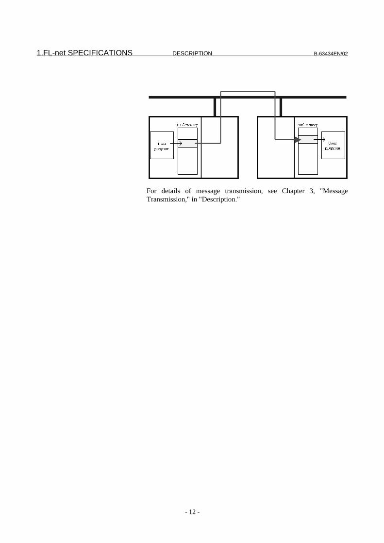
Message transmissionThe message transmission function is the other FL-net function.With this function, the user program also executes messagetransmission services via PMC memory areas.To perform message transmission, the user program writes thetransmission request code of message transmission in the PMCmemory area that has been set as an message transmission interface inadvance. The user program also reads received message data via aPMC memory area. Part of message transmission server (requestreceiver) processing may be performed in the FL-net board withoutuser-program intervention.
�������������������������� ���������
����������
����������������������������
�����������������
������������������
1.FL-net SPECIFICATIONS DESCRIPTION B-63434EN/02
- 12 -
For details of message transmission, see Chapter 3, "MessageTransmission," in "Description."
��������� ���������
����������
����������

B-63434EN/02 DESCRIPTION 2.CYCLIC TRANSMISSION
- 13 -
2 CYCLIC TRANSMISSION
This chapter details how to use the cyclic data transmission functionof the FL-net function with the Series 16i/18i/21i-A and with thePower Mate i.

2.CYCLIC TRANSMISSION DESCRIPTION B-63434EN/02
- 14 -
2.1 Common Memory Area 1 Cyclic Transmission
Those areas of common memory area 1 that are to be used for dataexchange can be allocated in the PMC R area in direct image.An area to be allocated needs to be set beforehand. If the setting ofan allocation area is changed, the power needs to be turned off thenback on.
Procedure
Set the following parameters beforehand:1) Pa11: Area 1 transmit data start address2) Pa12: Area 1 transmit data size (in words)3) Pa30: Allocation address4) Pa31: Area 1 address5) Pa32: Data size (in words)
If an allocated area includes a mixture of DI and DO areas as shownbelow, data exchange is performed by making a distinction between aDI area and a DO area, thus posing no problem. When 0 is set inPa32 (data size), the data of common memory area 1 is notexchanged.
����#+�# ���������� 0�( �(�"
� � � �� �
�+#�-$%��'#�#�*+)$
)�0�+��)'�-
�� �+#�-$%��'#�#�*+)$
)�0�+��)'�-
�
�+#�-$%��'#�#�)*��0�
()&#(��)'�
�+#�-$%��'#�#�*+)$
)�0�+��)'�-
�� �+#�-$%��'#�#�*+)$
)�0�+��)'�-
�+#�-$%��'#�#�*+)$
)�0�+��)'�-
�(7+�
�(7$�("$
�(7"�
�(""�

B-63434EN/02 DESCRIPTION 2.CYCLIC TRANSMISSION
- 15 -
2.2 Common Memory Area 2 Cyclic Transmission
When the data of common memory area 2 is exchanged, DI areasneed to be set separately from DO areas.In any case, a DI/DO area needs to be allocated in the PMC areabeforehand. If the setting of a DI/DO allocation area is changed, thepower needs to be turned off then back on. On the other hand, a partof common memory area 2 can be dynamically changed by the userprogram.There are two allocation methods for DI areas: ① method fordynamically changing DI data areas in node units and ② method forstatically fixing a DI data area independently of nodes.
2.2.1 DO data allocation
Procedure
Set the following parameters beforehand:1) Pa13: Area 2 transmit data start address2) Pa14: Area 2 transmit data size (in words)3) Pa40: Allocation address (for DO)4) Pa41: Data size (for DO) (in words)5) Pa43: Area 2 data exchange condition allocation address6) Pa44: Switch flag allocation address
Organization of area 2 data exchange condition allocation:
8 +
�2222<, �)'���=$1�+
�2222<� ���)**-���:%��/)+'-;
�2222< �#�#�-%>��:%��/)+'-;
�2222<5 � �)**-���:%��/)+'-;
Note) This function does not use the hatched portions.Procedure of dynamic change of common memory area 2 allocationby the user program:1) The user program specifies the following in the PMC D area
specified by Pa43 (area 2 data exchange condition allocationaddress):- DO offset
2) Then, the user program writes FFh to the area (switch flag) inthe PMC R area specified by Pa44 (switch flag allocationaddress).
3) The CNC monitors the switch flag at all times. When FFh iswritten, the node number, DI offset, data size, and DO offset setin the PMC D area are taken in as internal information, and theswitch flag is set to 00h.
�(%7�

2.CYCLIC TRANSMISSION DESCRIPTION B-63434EN/02
- 16 -
4) Until FFh is written to the switch flag, the CNC writes the DOdata in the PMC area specified by Pa40 (allocation address (forDO)) to common memory area 2, using the same DO offset.
�����( �(
�
�2222<, ����������
�2222<� ���--!�#
�2222< �(#(�!.9�
�2222<5 ����--!�#
��� �( �(
2222 �4.#'5�-1(3
���������� 0
( �(�$
� �
��� :��( �( � (�!�.#��(#(�- ��
�#5� �����!
� (�!�.#��(#(��-
#5��1�'(1�����
����(#(
� (�!�.#��(#(�- ��
�#5� �����!
NOTE1 When the offset is dynamically changed for DO data
allocation of common memory area 2, the nodenumber, DI offset, and data size are also changed.To change only the DO data offset, carefully changethe setting not to change other values.
2 There are the following restrictions on DO dataexchange:
- When 0 is set in Pa41 (data size), DO data exchangeis not performed.
- If a negative value is set in Pa43 (area 2 dataexchange condition allocation address), operationassumes that the DO offset is 0.
- If a negative value is set in Pa44 (switch flagallocation address), the DO offset cannot bedynamically changed.
- When (DO offset + Pa41) > Pa14, DO data exchangeis not performed.
�("%
�(%7�
�(%%�
�(%+�
�(%"
�("7�
B-63434EN/02 DESCRIPTION 2.CYCLIC TRANSMISSION
- 17 -
2.2.2 DI data allocation
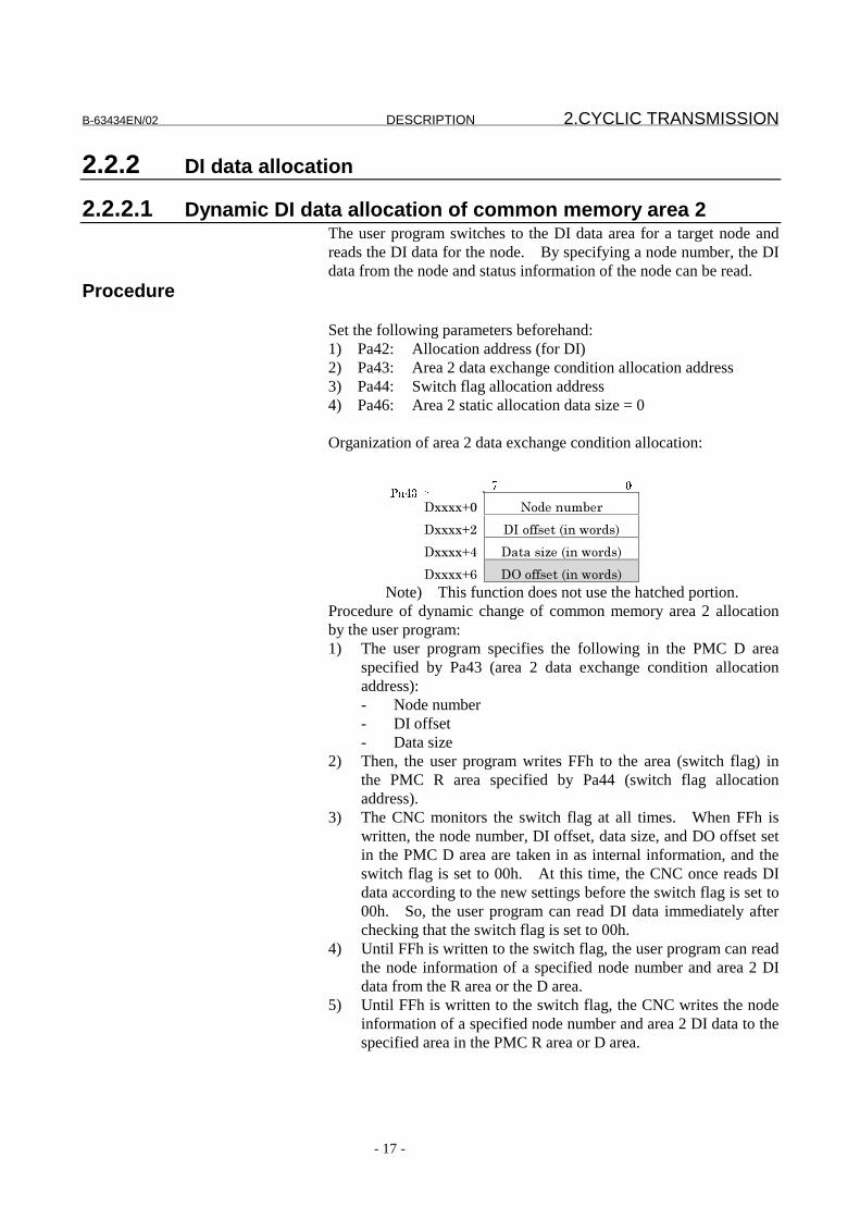
2.2.2.1 Dynamic DI data allocation of common memory area 2The user program switches to the DI data area for a target node andreads the DI data for the node. By specifying a node number, the DIdata from the node and status information of the node can be read.
Procedure
Set the following parameters beforehand:1) Pa42: Allocation address (for DI)2) Pa43: Area 2 data exchange condition allocation address3) Pa44: Switch flag allocation address4) Pa46: Area 2 static allocation data size = 0
Organization of area 2 data exchange condition allocation:
8 +
�2222<, �)'���=$1�+
�2222<� ���)**-���:%��/)+'-;
�2222< �#�#�-%>��:%��/)+'-;
�2222<5 � �)**-���:%��/)+'-;
Note) This function does not use the hatched portion.Procedure of dynamic change of common memory area 2 allocationby the user program:1) The user program specifies the following in the PMC D area
specified by Pa43 (area 2 data exchange condition allocationaddress):- Node number- DI offset- Data size
2) Then, the user program writes FFh to the area (switch flag) inthe PMC R area specified by Pa44 (switch flag allocationaddress).
3) The CNC monitors the switch flag at all times. When FFh iswritten, the node number, DI offset, data size, and DO offset setin the PMC D area are taken in as internal information, and theswitch flag is set to 00h. At this time, the CNC once reads DIdata according to the new settings before the switch flag is set to00h. So, the user program can read DI data immediately afterchecking that the switch flag is set to 00h.
4) Until FFh is written to the switch flag, the user program can readthe node information of a specified node number and area 2 DIdata from the R area or the D area.
5) Until FFh is written to the switch flag, the CNC writes the nodeinformation of a specified node number and area 2 DI data to thespecified area in the PMC R area or D area.
�(%7�

2.CYCLIC TRANSMISSION DESCRIPTION B-63434EN/02
- 18 -
�����( �(
�
�2222<, ����������
�2222<� ���--!�#
�2222< �(#(�!.9�
�2222<5 ����--!�#
��� �( �(
2222 �4.#'5�-1(3
���������� 0
( �(�$
� �
��� :��( �( � (�!�.#��(#(�- ��
�#5� �����!
� (�!�.#��(#(�- ��
������������������������� �#5� �����!
���(#( � (�!�.#��(#(�- ��
�#5� �����!
� (�!�.#��(#(�- ��
�#5� �����!
�(%7�
�(%%�
�(%$�
:��#�;

B-63434EN/02 DESCRIPTION 2.CYCLIC TRANSMISSION
- 19 -
NOTE1 When node information or DI data is dynamicallychanged for dynamic DI data allocation of commonmemory area 2, the DO offset is also changed. Tochange only the DI data, carefully change the settingnot to change another value.2 Information on other nodes is 4 bytes in size.So, for an area in the R area to be allocated for DI,allocate an area 4 bytes larger than the value set inDxxxx+4 (data size (in words).When the user program handles DI data in area 2, thedata at the address 4 bytes shifted from the addressset in Pa42 (allocation address (for DI)) is handled.
3 There are the following restrictions on dynamic DIdata exchange:
- Set a value of 0 in Pa46 (area 2 static allocation datasize).
- If a negative value is set in Pa42 (allocation address(for DI)), transfer of information on other nodes andDI data exchange are not performed.
- If a negative value is set in Pa43 (area 2 dataexchange condition allocation address), transfer ofinformation on other nodes and DI data exchangeare not performed.
- If 0 is specified in Dxxxx+4 (data size) specified byPa43 (area 2 data exchange condition allocationaddress), transfer of information on other nodes isperformed, but DI data exchange is not performed.
- If a negative value is set in Pa44 (switch flagallocation address), the DI data source cannot bedynamically changed.
- For reasons related to the specifications of theFANUC FL-net board, set Pa32 (data size), Pa41(data size), and Dxxxx+4 (data size) so that the totalsize of them is 1024 words or less.
4 When DI data exchange is performed with a sizespecification with which the local node transmit dataarea is contained, data transfer from the commonmemory area to the PMC area may overwrite thePMC area data with the common memory data.Carefully specify the data size so that the local nodetransmit data area is not contained.
-

2.CYCLIC TRANSMISSION DESCRIPTION B-63434EN/02
- 20 -
2.2.2.2 Static DI data allocation of common memory area 2This allocation method fixes the DI data area. With this method, anarea larger than that allocated with the dynamic allocation method canbe allocated in the PMC area.Only node status information can be read by dynamic change.
Procedure
Set the following parameters beforehand:1) Pa42: Allocation address (for DI)2) Pa43: Area 2 data exchange condition allocation address3) Pa44: Switch flag allocation address4) Pa45: Area 2 static allocation start address5) Pa46: Area 2 static allocation data size (in words)
Organization of area 2 data exchange condition allocation:
8 +
�2222<, �)'���=$1�+
�2222<� ���)**-���:%��/)+'-;
�2222< �#�#�-%>��:%��/)+'-;
�2222<5 � �)**-���:%��/)+'-;
Note) This function does not use the hatched portions.Procedure of node information change by the user program:The node information on the specified node can dynamically bechecked using the following procedure:1) The user program specifies the following in the PMC D area
specified by Pa43 (area 2 data exchange condition allocationaddress):- Node number
2) Then, the user program writes FFh to the area (switch flag) inthe PMC R area specified by Pa44 (switch flag allocationaddress).
3) The CNC monitors the switch flag at all times. When FFh iswritten, the node number, and DO offset set in the PMC D areaare taken in as internal information, and the switch flag is set to00h. At this time, the CNC once updates the specified nodestatus information according to the new settings before theswitch flag is set to 00h. So, the user program can read thestatus information immediately after checking that the switchflag is set to 00h.
4) Until FFh is written to the switch flag, the user program can readthe node information of a specified node number from the R areaor the D area.
5) Until FFh is written to the switch flag, the CNC writes the nodeinformation of a specified node number to the specified area inthe PMC R area or D area. The DI data can be read regardlessof whether the switch flag is set to 00h.
�(%7�

B-63434EN/02 DESCRIPTION 2.CYCLIC TRANSMISSION
- 21 -
�����( �(
�
�2222<, ����������
�2222<� ���--!�#
�2222< �(#(�!.9�
�2222<5 ����--!�#
��� �( �(
2222 �4.#'5�-1(3
���������� 0
( �(�$
� �
��� :��( �( � (�!�.#��(#(�- ��
�#5� �����!
� (�!�.#��(#(�- ��
������������������������� �#5� �����!
���(#( � (�!�.#��(#(��-
#5��1�'(1�����
� (�!�.#��(#(�- ��
�#5� �����!
�(%7�
�(%%�
�(%$�
:��#�;
�(%+�
�(%;
�(%"
2.CYCLIC TRANSMISSION DESCRIPTION B-63434EN/02
- 22 -
NOTE1 As shown in the above example, the area specified by
Pa46 (area 2 static allocation data size (in words))can contain the local node transmit data area. Inthis case, the corresponding PMC area can bespecified for Pa40 (allocation address (for DO)) toallocate no wasted PMC area.To make such a setting, however, carefully set Pa40(allocation address (for DO)) not to duplicate PMCarea setting.
2 Node information can also be changed dynamicallywith static DI data allocation of common memoryarea 2. When node information is changed,however, the DO offset is also changed. To changeonly the node information, carefully change thesetting not to change the DO offset.
3 Information on other nodes is 4 bytes in size.So, for an area in the R area to be allocated for DI,allocate an area 4 bytes larger than the value set inPa46 (area 2 static allocation data size (in words)).When the user program handles DI data in area 2,the data at the address 4 bytes shifted from theaddress set in Pa42 (allocation address (for DI)) ishandled.
4 There are the following restrictions on static DI dataexchange:
- When a value of 0 is specified for Pa46 (area 2 staticallocation data size (in words)), DI data exchangewith dynamic allocation is performed.
- If a negative value is set in Pa42 (allocation address(for DI)), transfer of information on other nodes andDI data exchange are not performed.
- If a negative value is set in Pa43 (area 2 dataexchange condition allocation address), transfer ofinformation on other nodes are not performed.
- If a negative value is set in Pa44 (switch flagallocation address), node information cannotdynamically be changed.
2.2.2.3 Nodes information
B-63434EN/02 DESCRIPTION 2.CYCLIC TRANSMISSION
- 23 -
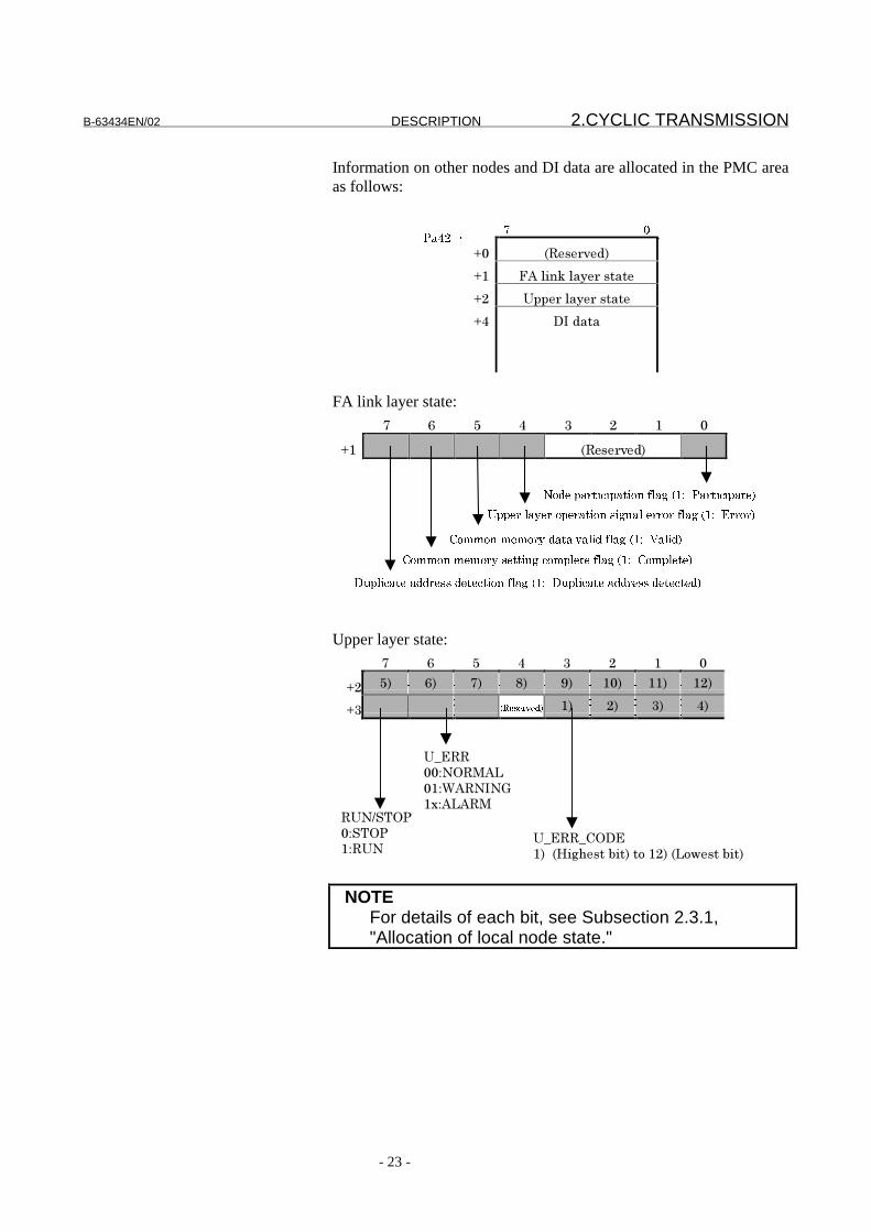
Information on other nodes and DI data are allocated in the PMC areaas follows:
8 +
<, :�-�+?�';
<� ���(%�@�(#"�+�-�#��
<� �AA�+�(#"�+�-�#��
< ���'#�#
FA link layer state:
� 5 ! � � � ,
<� :�-�+?�';
������������������� ��������������������������
�����������������������������������
����������� �����������������������������
�������������� �������������������������������� ��������
�������������������������������������
Upper layer state:
� 5 ! � � � ,
<� !; 5; �; �; 4; �,; ��; ��;
<� ���������� �; �; �; ;
�B�
,,C� ���
,�C������
�2C����
�B�B ��
�;��:7%.0�-��1%�;��)���;�:�)/�-��1%�;
��6�� �
,C�� �
�C��
NOTEFor details of each bit, see Subsection 2.3.1,"Allocation of local node state."
�(%$�
2.CYCLIC TRANSMISSION DESCRIPTION B-63434EN/02
- 24 -
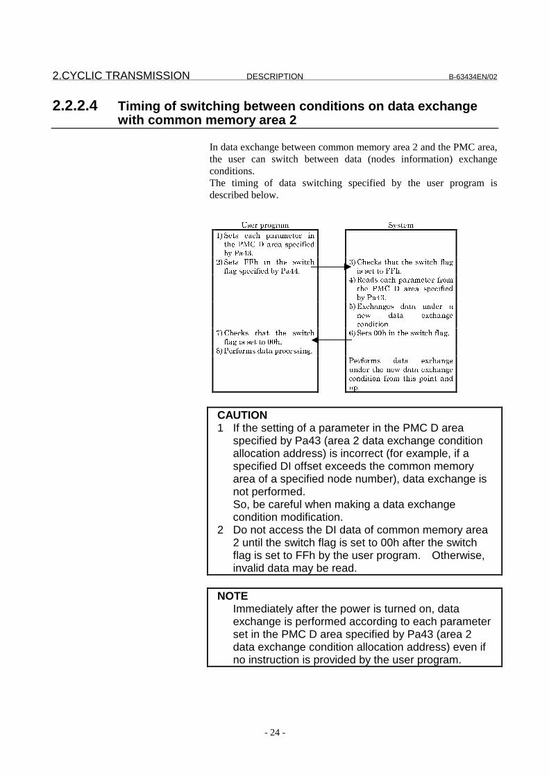
2.2.2.4 Timing of switching between conditions on data exchangewith common memory area 2
In data exchange between common memory area 2 and the PMC area,the user can switch between data (nodes information) exchangeconditions.The timing of data switching specified by the user program isdescribed below.
�!� �< �3 (� �0!#��
"/ ��#!� �('5� <( (��#� � .�#5�������( �(�!<�'.-.���0��(%7)
$/ ��#!� ��5� .�� #5�� !4.#'5-1(3�!<�'.-.����0��(%%)
7/ 5�'6!�#5(#�#5��!4.#'5�-1(3.!�!�#�#����5)
%/ �(�!��('5�<( (��#� �- ��#5�� ��� �� ( �(� !<�'.-.���0��(%7)
*/ �='5(�3�!� �(#(� ���� � (��4� �(#(� �='5(�3�'���.#.��)
8/ 5�'6!� #5(#� #5�� !4.#'5-1(3�.!�!�#�#��++5)
;/ ��#!�++5�.��#5��!4.#'5�-1(3)
>/ �� -� �!��(#(�< �'�!!.�3)
�� -� �!� �(#(� �='5(�3����� � #5����4��(#(��='5(�3�'���.#.��� - ��� #5.!� <�.�#� (���<)
CAUTION1 If the setting of a parameter in the PMC D area
specified by Pa43 (area 2 data exchange conditionallocation address) is incorrect (for example, if aspecified DI offset exceeds the common memoryarea of a specified node number), data exchange isnot performed.So, be careful when making a data exchangecondition modification.
2 Do not access the DI data of common memory area2 until the switch flag is set to 00h after the switchflag is set to FFh by the user program. Otherwise,invalid data may be read.
NOTEImmediately after the power is turned on, dataexchange is performed according to each parameterset in the PMC D area specified by Pa43 (area 2data exchange condition allocation address) even ifno instruction is provided by the user program.

B-63434EN/02 DESCRIPTION 2.CYCLIC TRANSMISSION
- 25 -
2.3 Node State Monitoring
2.3.1 Allocation of local node state
The state of the local node can be monitored by allocating the 6-bytestate code of the local node in the PMC R area.If a negative value is set in Pa20 (local node information address),local node information is not posted.
Procedure
Set the following parameter beforehand:1) Pa20: Local node information address
Local node information is allocated in the PMC R area as follows:
8 +
<, �)&#(��)'��-�#��
<� ���(%�@�-�#��
<� �AA�+�(#"�+�-�#��
< =++������?#(=�
Local node state:
� 5 ! � � � ,
<, :�-�+?�';
��������������������� ��������������
����������������������� ������������������
������������������� �������������������������
����������������� ������������������������
Table 2-1 Local Node State
Item DescriptionToken monitoring timeerror flag
Set when transmission does notterminate within the token monitoringtime (Pa15) set for the local node.
Initialization error flag Set when an initialization parameter ora parameter set again is invalid.
Reception wait stateflag
Set when the node enters the framereception wait state without receivingany frame during network initialization.
Duplicate node numberflag
Set when a node having the same nodenumber as for the local node is detectedin the network.
�($+�

2.CYCLIC TRANSMISSION DESCRIPTION B-63434EN/02
- 26 -
FA link state:
� 5 ! � � � ,
<� :�-�+?�';
������������������� ��������������������������
�����������������������������������
����������� �����������������������������
�������������� �������������������������������� ��������
�������������������������������������
Table 2-2 FA Link State
Item DescriptionNode participation flag Indicates whether the node participates
in the network (1) or is disconnectedfrom the network (0).
Upper layer operationsignal error flag
Currently, not supported.
Common memory datavalid flag
Set when cyclic data is valid, in otherwords, when PMC area allocation isnormal.
Common memorysetting complete flag
Set when node common memorysetting is complete, in other words,when the parameters related to thecommon memory setting (Pa11, Pa12,Pa13, and Pa14) are valid.
Duplicate addressdetection flag
Set when a common memory setting fora node connected to the network isduplicate, in other words, when thevalue specified for a parameter (Pa11,Pa12, Pa13, or Pa14) for another deviceis specified for a parameter related tothe common memory setting (Pa11,Pa12, Pa13, or Pa14).
Upper layer state:
� 5 ! � � � ,
<� !; 5; �; �; 4; �,; ��; ��;
<� ���������� �; �; �; ;
�B�
,,C� ���
,�C������
�2C���� �B�B ��
�;��:7%.0�-��1%�;��)���;�:�)/�-��1%�;
:�0%-�&)'��%-��)��=-�'�/%�0��0%-
'�?%&��;
��6�� �
,C�� �
�C��

B-63434EN/02 DESCRIPTION 2.CYCLIC TRANSMISSION
- 27 -
Table 2-3 Upper Layer State
Item DescriptionU_ERR_CODE Currently, not supported.U_ERR Currently, not supported.RUN/STOP The RUN/STOP state of the PMC
ladder program is set.
Current RCT value:
� 5 ! � � � ,
< 4; �,; ��; ��; ��; � ; �!; �5;
<! �; �; �; ; !; 5; �; �;
Current RCT value:1) (Highest bit) to 16) (Lowest bit)
RCT (Refresh Cycle Time):120% of the real time required for a token to pass throughall nodes (Unit: ms)
2.CYCLIC TRANSMISSION DESCRIPTION B-63434EN/02
- 28 -
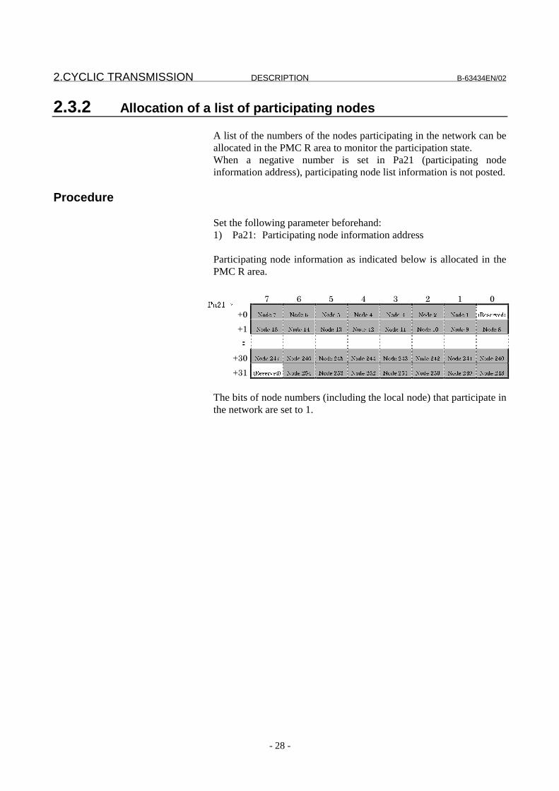
2.3.2 Allocation of a list of participating nodes
A list of the numbers of the nodes participating in the network can beallocated in the PMC R area to monitor the participation state.When a negative number is set in Pa21 (participating nodeinformation address), participating node list information is not posted.
Procedure
Set the following parameter beforehand:1) Pa21: Participating node information address
Participating node information as indicated below is allocated in thePMC R area.
� 5 ! � � � ,
<, ����� ������ ������ ������ ������ ������ ����� ����������
<� ����� � ����� � ����� � ����� � ����� ����� � ������ �����
:
<�, ������� �������� �������� �������� �������� �������� ������� ��������
<�� ���������� �������� �������� �������� ������� �������� �������� �������
The bits of node numbers (including the local node) that participate inthe network are set to 1.
�($"�

B-63434EN/02 DESCRIPTION 2.CYCLIC TRANSMISSION
- 29 -
2.4 Byte List of Cyclic Data
A byte list in a common memory area is related with a byte list in thePMC area as described below.
Common memory area 1 and the PMC area
���������� 0�( �(�" ���#+�#
"* + 8 +
<,,,, ��� 7 <,, � 7
<,,,� !5��7 <,� ��7
<,� ��7
<,� !57
Common memory area 2 and the PMC area
���������� 0�( �(�$ ���#+�#
"* + 8 +
<,,,, ��� 7 <,, � 7
<,,,� !5��7 <,� ��7
<,� ��7
<,� !57
NOTEThe data width of each address in a commonmemory area of the FL-net is 16 bits.On the other hand, the data width of each address inthe PMC area is 8 bits. So, data is exchangedbetween the common memory areas and the PMCarea according to the relationships shown above.
2.CYCLIC TRANSMISSION DESCRIPTION B-63434EN/02
- 30 -
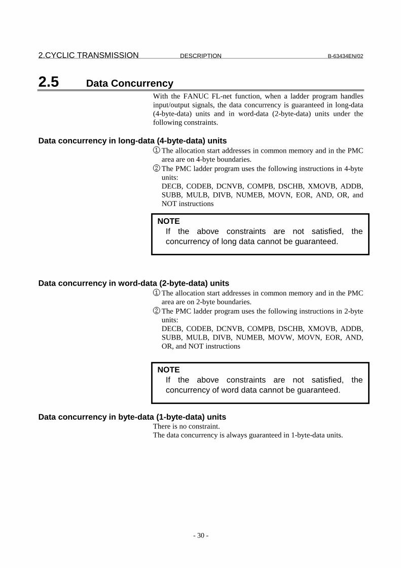
2.5 Data ConcurrencyWith the FANUC FL-net function, when a ladder program handlesinput/output signals, the data concurrency is guaranteed in long-data(4-byte-data) units and in word-data (2-byte-data) units under thefollowing constraints.
Data concurrency in long-data (4-byte-data) units① The allocation start addresses in common memory and in the PMC
area are on 4-byte boundaries.② The PMC ladder program uses the following instructions in 4-byte
units:DECB, CODEB, DCNVB, COMPB, DSCHB, XMOVB, ADDB,SUBB, MULB, DIVB, NUMEB, MOVN, EOR, AND, OR, andNOT instructions
Data concurrency in word-data (2-byte-data) units① The allocation start addresses in common memory and in the PMC
area are on 2-byte boundaries.② The PMC ladder program uses the following instructions in 2-byte
units:DECB, CODEB, DCNVB, COMPB, DSCHB, XMOVB, ADDB,SUBB, MULB, DIVB, NUMEB, MOVW, MOVN, EOR, AND,OR, and NOT instructions
Data concurrency in byte-data (1-byte-data) unitsThere is no constraint.The data concurrency is always guaranteed in 1-byte-data units.
NOTEIf the above constraints are not satisfied, theconcurrency of word data cannot be guaranteed.
NOTEIf the above constraints are not satisfied, theconcurrency of long data cannot be guaranteed.

B-63434EN/02 DESCRIPTION 2.CYCLIC TRANSMISSION
- 31 -
When handling data input from the FL-net, note the following points:
NOTE1 When the PMC R area or D area is used as the input
data area, the synchronous buffer in the PMC is notused. For this reason, input data may change duringladder 1 scan.In other words, the value updated via the FL-net maybe read, depending on the read timing, even when theladder program handles data in the same area.
2 The concurrency of data longer than long data (4-bytedata) is not guaranteed. To establish theconcurrency of such data, see "Measures to guaranteethe concurrency of multiple-byte data" following.

2.CYCLIC TRANSMISSION DESCRIPTION B-63434EN/02
- 32 -
Measures to guarantee the concurrency of multiple-byte data
An example of handling input data of multiple-byte on the secondladder level to guarantee its concurrency is given below. Toestablish the concurrency of data tens to hundreds of bytes long, it issimple to perform data transmission with transmission of a messagewith confirmation. For details of transmission of a message withconfirmation, see Section 3.7, "Server Function of Transmitting aMessage with Confirmation."
Example of measures: Control using a flag for synchronization
This control method provides a flag for synchronization before andafter multiple-byte data to synchronize the data. An example ofguaranteeing the concurrency of 6-byte data is described below.
1) Data structureA flag for synchronization is provided in the byte preceding the2-byte data and in the byte following the 2-byte data, thusextending the 2-byte data to 8-byte data.
R0099 Flag 1 forsynchronization
R0100 Data sectionR0105R0106 Flag 2 for
synchronization
2) Processing by the data writing sideThe data is updated according to the procedure below.(1) Flag 1 for synchronization is incremented.(2) The data section is updated.(3) The same value as flag 1 for synchronization is set in flag 2
for synchronization.
3) Processing by the data reading sideThe data is processed according to the procedure below.(1) The eight bytes starting with R0099 are copied to the area
for synchronization (R0199) at the start of the second level.(2) A check is made to see if R0199 = R0206.(3) If R0199 = R0202, R0200 is processed as 6-byte data.
CAUTIONIf the size of data to be synchronized is increased bycombining many bytes of data at a time, the datamay not be synchronized easily.In such a case, divide the data at each variable, forexample, and provides flags for synchronization.
B-63434EN/02 DESCRIPTION 2.CYCLIC TRANSMISSION
- 33 -
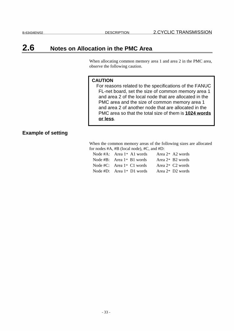
2.6 Notes on Allocation in the PMC Area
When allocating common memory area 1 and area 2 in the PMC area,observe the following caution.
Example of setting
When the common memory areas of the following sizes are allocatedfor nodes #A, #B (local node), #C, and #D:
Node #A: Area 1→A1 words Area 2→A2 wordsNode #B: Area 1→B1 words Area 2→B2 wordsNode #C: Area 1→C1 words Area 2→C2 wordsNode #D: Area 1→D1 words Area 2→D2 words
CAUTIONFor reasons related to the specifications of the FANUCFL-net board, set the size of common memory area 1and area 2 of the local node that are allocated in thePMC area and the size of common memory area 1and area 2 of another node that are allocated in thePMC area so that the total size of them is 1024 wordsor less.

2.CYCLIC TRANSMISSION DESCRIPTION B-63434EN/02
- 34 -
Example: Allocating DO data of local node B and DI data of node C in the PMC area
Assume that the size of allocation of area 1 in the PMC area is 512words (all of common memory area 1). Also assume that the size ofDO data in area 2 of the local node that is allocated in the PMC areais B2" words. In this case, allocation of DI data in area 2 of node #Cin the PMC area is performed as follows:When B1 + C1 + B2" + C2 <= 1024, all of C2 words can be allocated.When B1 + C1 + B2" + C2 > 1024, up to 1024 - B1 - C1 - B2" (=C2") words can be allocated.
���( �( !�������"������
� � � � � � � � � � � � � � � � � � � � � � � �� � � � � � � � � � � � � � � � � � � � � �
?�
?�
?�
?
?
?
?�
?�
?�
?�
!�������"�������
�� � � � � � � � � � � � � � � � � � � � � �
?�
?�
?�
?
?
?
?�
?�
?�
?�
��������
����#��������$���
%�&�#����
�������
��������
�������
�������
������
!�&�#����
NOTEWhen all of common memory area 1 is allocated in thePMC area, the value to be noted is also the sum of thesizes of allocation of the local node area and anothernode area in the PMC area.In other words, when DI data of node #D is read underthe same conditions as for the above example, DIdata in common memory area 2 that satisfies (1024 -B1 - D1 - B2”) can be read at a time.

B-63434EN/02 DESCRIPTION 3.MESSAGE TRANSMISSION
- 35 -
3 MESSAGE TRANSMISSION
This chapter details how to use the message transmission function ofthe FL-net function with the Series 16i/18i/21i-A with the PowerMate i.

3.MESSAGE TRANSMISSION DESCRIPTION B-63434EN/02
- 36 -
3.1 List of Message Transmission Services
The message transmission function of the FANUC FL-net functionsupports the services listed in Table 3-1.
Table 3-1 List of Services SupportedMessage service item Client function Server function
Byte block read � �
Byte block write � �
Word block read � �
Word block write � �
Network parameter read - �
Network parameter write - �
Stop command - -Start command - -Profile read - �
Log data read - �
Log data clear - �
Transparent message � (Note) � (Note)Echo back message (for test) - �
NOTEAmong the transaction codes assigned to transparentmessages, 50000 to 59999 are used for thistransparent message.

B-63434EN/02 DESCRIPTION 3.MESSAGE TRANSMISSION
- 37 -
3.2 Procedure of the Message Transmission Function
The function for transmitting messages other than transparentmessages involves a client function and server function. For amessage transmitted from the client, the server returns a responsemessage. In short, the client is a service requester, and the server isa service receiver.
With the server function for each type of message transmission of theFANUC FL-net function, a response message is automaticallyreturned to the client without involving the user program in responseto a received message. With the client function, the user programtransmits a message by using the interface area set by Pa50 (interfaceallocation address).
Client Server
User program User program
System System
FL-net
A transparent message can be handled freely by the user programwithout making a client/server distinction. So, two interface areasare required: one for transmission and the other for reception. Asthe transmit interface area, the interface area set by Pa50 (interfaceallocation address) used with a client message is used. As thereceive interface area, the interface area set by Pa52 (transparentreceive message allocation address) is used.
User program User program
System System
FL-net
�D=�-��$�--#.�
�-A)�-��$�--#.�
��--#.�
��--#.�

3.MESSAGE TRANSMISSION DESCRIPTION B-63434EN/02
- 38 -
The format of each interface area is described below.
Transmit interface for the client and transparent messages
The interface area specified by Pa50 (interface allocation address) hasthe format shown below.
7 0+0 Transmission
request/response flag+2 Request status (R_STS)+3 Response status
(M_RLT)+4 Cancel flag+5 Destination node
number+6 (Reserved)
+8 Message section
NOTEThe message section does not include a data bufferarea.
�(*+�
�(*"
B-63434EN/02 DESCRIPTION 3.MESSAGE TRANSMISSION
- 39 -
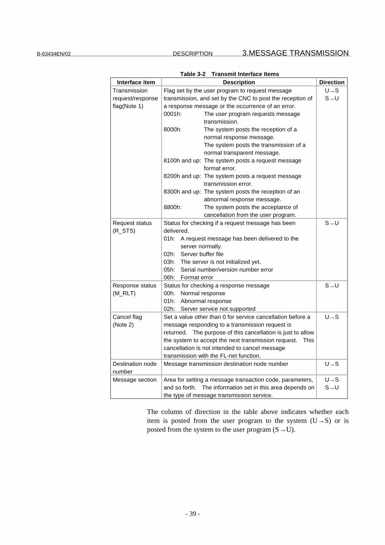
Table 3-2 Transmit Interface ItemsInterface item Description Direction
Transmissionrequest/responseflag(Note 1)
Flag set by the user program to request messagetransmission, and set by the CNC to post the reception ofa response message or the occurrence of an error.0001h: The user program requests message
transmission.8000h: The system posts the reception of a
normal response message.The system posts the transmission of anormal transparent message.
8100h and up: The system posts a request messageformat error.
8200h and up: The system posts a request messagetransmission error.
8300h and up: The system posts the reception of anabnormal response message.
8800h: The system posts the acceptance ofcancellation from the user program.
U→SS→U
Request status(R_STS)
Status for checking if a request message has beendelivered.01h: A request message has been delivered to the
server normally.02h: Server buffer file03h: The server is not initialized yet.05h: Serial number/version number error06h: Format error
S→U
Response status(M_RLT)
Status for checking a response message00h: Normal response01h: Abnormal response02h: Server service not supported
S→U
Cancel flag(Note 2)
Set a value other than 0 for service cancellation before amessage responding to a transmission request isreturned. The purpose of this cancellation is just to allowthe system to accept the next transmission request. Thiscancellation is not intended to cancel messagetransmission with the FL-net function.
U→S
Destination nodenumber
Message transmission destination node number U→S
Message section Area for setting a message transaction code, parameters,and so forth. The information set in this area depends onthe type of message transmission service.
U→SS→U
The column of direction in the table above indicates whether eachitem is posted from the user program to the system (U→S) or isposted from the system to the user program (S→U).

3.MESSAGE TRANSMISSION DESCRIPTION B-63434EN/02
- 40 -
CAUTIONEnsure that while the transmission request/responseflag is set to 0001h, the user program does not rewritethe data in this interface area. Otherwise, messagetransmission may not be terminated normally.
NOTE1 When a service is terminated normally, 8000h is
returned to this flag. If a value other than 8000h isreturned, check the value, and resolve the problem.See Table 3-3 for the error codes returned from thesystem.
2 After a message transmission request is made, thisinterface does not allow the next transmissionrequest to be made until a response message isreceived or an error occurs. So, if a responsemessage cannot be received for a cause on theserver, the next message transmission requestcannot be made until the power is turned off. Insuch a case, the cancel flag allows the system to exitfrom the response message wait state and wait forthe next message transmission request. Thepurpose of this cancellation is just to allow thesystem to accept the next message transmissionrequest. This cancellation is not intended to cancelmessage transmission with the FL-net function.(The FL-net function does not have a function forcanceling message transmission.) This means thatwhen this cancellation function is used, the responsemessage for the previous message request may betreated as a response to the next message requestby mistake.

B-63434EN/02 DESCRIPTION 3.MESSAGE TRANSMISSION
- 41 -
Table 3-3 Error Codes of the Transmit InterfaceError code Description
8101h A specified node number is incorrect.8102h A specified transaction code is incorrect.8103h An area specified as a transmit/receive buffer in the PMC R
area exceeds the allowable range.8104h In word block data, an odd address is specified as a
transmit/receive buffer area in the PMC R area.8105h Excessive data size8202h Server buffer file8203h The server is not initialized yet.8205h Server serial number/version number error8206h Server format error8210h Retry failure (no response from the server)8301h Abnormal response reception8302h Server service not supported

3.MESSAGE TRANSMISSION DESCRIPTION B-63434EN/02
- 42 -
Receive interface for transparent messages
The interface area specified by Pa52 (transparent receive messageallocation address) has the format shown below.
7 0+0 Receive flag
+2 Transmission source nodenumber
+3 (Reserved)+4 Transaction code
+6 Size
+8 Data
Table 3-4 Transparent Message Receive Interface ItemsInterface item Description Direction
Receive flag Flag used by the system to post the reception of atransparent message to the user program.0001h: The system posts the reception of a transparent
message.0000h: The user program posts the completion of
message receive processing.
S→UU→S
Transmissionsource nodenumber
Transparent message transmission source node number S→U
Transaction code Transaction code of a received transparent message S→USize Number of words of data contained in a received
transparent messageS→U
Data Data contained in a received transparent message S→U
�(*$�
�(*7
B-63434EN/02 DESCRIPTION 3.MESSAGE TRANSMISSION
- 43 -
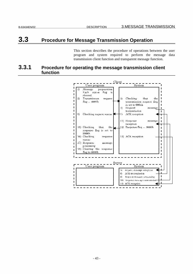
3.3 Procedure for Message Transmission Operation
This section describes the procedure of operations between the userprogram and system required to perform the message datatransmission client function and transparent message function.
3.3.1 Procedure for operating the message transmission clientfunction
(%���
�-�+�A+).+#$ �"-��$
"/ ��!!(3�� < �<( (#.���('5� !#(#�!� -1(3� .!'1�( ��)
$/ � (�!�.!!.��� �@��!#-1(3�←�+++"5
7/ 5�'6.�3� #5(#� #5�# (�!�.!!.��� �@��!#� -1(3.!�!�#�#��+++"5
%/ �@��!#� ��!!(3�# (�!�.!!.��
>/ 5�'6.�3� �@��!#�!#(#�! 8/ ��� �'�<#.��
""/ �!<��!�� ��!!(3� �'�<#.��
"*/ 5�'6.�3� #5(#� #5� �!<��!�� -1(3� .!� !�#� #�>+++5)
"$/ �!<��!��-1(3�←�>+++5
";/ 5�'6.�3� �!<��!�!#(#�!
"7/ ��� �'�<#.��
"8/ �!<��!�� ��!!(3�< �'�!!.�3
">/ 1�( .�3� #5�� �!<��!�-1(3�#��++++5
��+?�+
�-�+�A+).+#$ �"-��$
�� � �� ���� ���� �� � �����
�� ���������������
�� � �� ���� ���� ����� �����
��� �������������������� �� ��
��� ���� � �����

3.MESSAGE TRANSMISSION DESCRIPTION B-63434EN/02
- 44 -
3.3.2 Procedure for operating the transparent messagetransmission function
� (�!<( ��#���!!(3��# (�!�.!!.���!.��
�!� �< �3 (� �0!#��
"/ � (�!<( ��#� ��!!(3�< �<( (#.���('5� !#(#�!� -1(3� .!'1�( ��)
$/ � (�!�.!!.��� �@��!#-1(3�←�+++"5
7/ 5�'6.�3� #5(#� #5�# (�!�.!!.��� �@��!#� -1(3.!�!�#�#��+++"5
%/ � (�!<( ��#� ��!!(3�# (�!�.!!.��
"$/ 5�'6.�3� �@��!#�!#(#�! ""/ ��� �'�<#.��"%/ 5�'6.�3� #5(#� #5�
'��<1�#.��� -1(3� .!� !�#� #�>+++5
"7/ ��<1�#.���-1(3�←�>+++5
"*/ 1�( .�3� #5�� '��<1�#.��-1(3�#��++++5
� (�!<( ��#���!!(3�� �'�<#.���!.��
�!� �< �3 (� �0!#��
*/ � (�!<( ��#� ��!!(3� �'�<#.��
;/ ���# (�!�.!!.��>/ 5�'6.�3� #5(#� #5�
�'�.A�� -1(3� .!� !�#� #�+++"5
8/ �'�.A��-1(3�←�+++"5
&/ �'�.A�� ��!!(3�< �'�!!.�3
"+/ 1�( .�3�#5�� �'�.A��-1(3#��++++5

B-63434EN/02 DESCRIPTION 3.MESSAGE TRANSMISSION
- 45 -
3.4 Message Transmission Client Function
This section describes the detailed interface of each service of themessage transmission client function.
3.4.1 Byte block read
Request message Response message7 0 7 0
+0 Transmission requestflag
0001h
+0 Response flag
+2 +2 Request status+3 +3 Response status+4 Cancel flag +4+5 Destination node
number+5
+6 (Reserved) +6 (Reserved)+8 Transaction code
65003+8 Transaction code
65203+10 (Reserved) +10 (Reserved)
+12 Offset address onvirtual address space
+12 Offset address onvirtual address space
+16 Data size +16 Data size
+18 Read data buffer startaddress
+18 Read data buffer startaddress
(Reserved) Read data
�(*+�
�(*"

3.MESSAGE TRANSMISSION DESCRIPTION B-63434EN/02
- 46 -
Table 3-5 Byte Block Read Interface ItemsInterface item Description Direction
Transaction code Request message: 65003Response message: 65203
U→SS→U
Offset address onvirtual addressspace
Request message: Offset address on virtual addressspace of byte block data to be readfrom the server
Response message: Same as above
U→S
Data size Request message: Size of byte block data to be readfrom the server (in bytes)
Response message: Size of byte block data actuallyread from the server (in bytes)
U→SS→U
Read data bufferstart address
Request message: Start address of an area in thePMC R area used to store byteblock data read from the server
Response message: Same as above
U→S
Read data Request message: ReservedResponse message: Byte block data actually read from
the server. When an abnormalresponse is returned, an error codeis stored.
S→U
NOTEFor an error code stored when an abnormalresponse is returned, refer to the manual of theequipment of a message transmission destination.

B-63434EN/02 DESCRIPTION 3.MESSAGE TRANSMISSION
- 47 -
3.4.2 Byte block write
Request message Response message7 0 7 0
+0 Transmission requestflag
0001h
+0 Response flag
+2 +2 Request status+3 +3 Response status+4 Cancel flag +4+5 Destination node
number+5
+6 (Reserved) +6 (Reserved)+8 Transaction code
65004+8 Transaction code
65204+10 (Reserved) +10 (Reserved)
+12 Offset address onvirtual address space
+12 Offset address onvirtual address space
+16 Data size +16 Data size
+18 Write data buffer startaddress
+18 Write data buffer startaddress
Write data (Reserved)Error code when an
abnormal response isreturned
�(*+�
�(*"

3.MESSAGE TRANSMISSION DESCRIPTION B-63434EN/02
- 48 -
Table 3-6 Byte Block Write Interface ItemsInterface item Description Direction
Transaction code Request message: 65004Response message: 65204
U→SS→U
Offset address onvirtual addressspace
Request message: Offset address on virtual addressspace of byte block data to bewritten to the server
Response message: Same as above
U→S
Data size Request message: Size of byte block data to be writtento the server (in bytes)
Response message: Size of byte block data actuallywritten to the server (in bytes)
U→SS→U
Write data bufferstart address
Request message: Start address of an area in thePMC R area storing byte block datato be written to the server
Response message: Same as above
U→S
Write data Request message: Byte block data to be written to theserver
Response message: An error code is stored when anabnormal response is returned.
U→SS→U
NOTEFor an error code stored when an abnormalresponse is returned, refer to the manual of theequipment of a message transmission destination.

B-63434EN/02 DESCRIPTION 3.MESSAGE TRANSMISSION
- 49 -
3.4.3 Word block read
Request message Response message7 0 7 0
+0 Transmission requestflag
0001h
+0 Response flag
+2 +2 Request status+3 +3 Response status+4 Cancel flag +4+5 Destination node
number+5
+6 (Reserved) +6 (Reserved)+8 Transaction code
65005+8 Transaction code
65205+10 (Reserved) +10 (Reserved)
+12 Offset address onvirtual address space
+12 Offset address onvirtual address space
+16 Data size +16 Data size
+18 Read data buffer startaddress
+18 Read data buffer startaddress
(Reserved) Read data
�(*+�
�(*"
3.MESSAGE TRANSMISSION DESCRIPTION B-63434EN/02
- 50 -
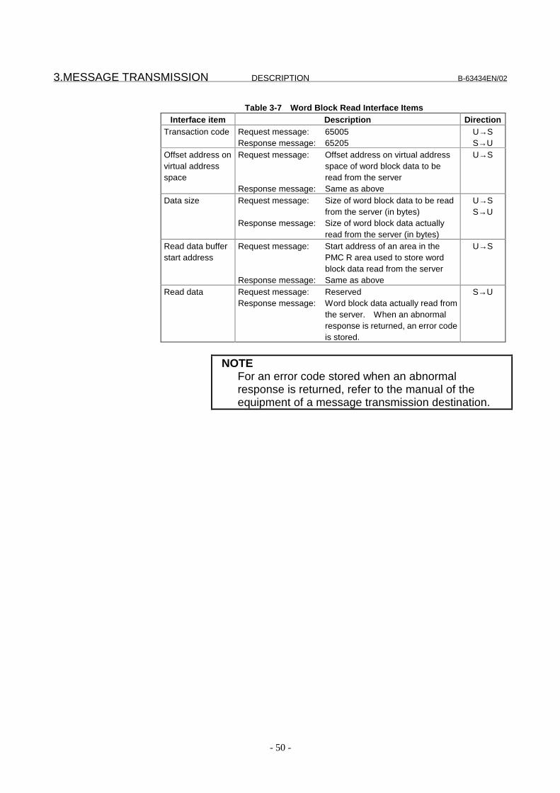
Table 3-7 Word Block Read Interface ItemsInterface item Description Direction
Transaction code Request message: 65005Response message: 65205
U→SS→U
Offset address onvirtual addressspace
Request message: Offset address on virtual addressspace of word block data to beread from the server
Response message: Same as above
U→S
Data size Request message: Size of word block data to be readfrom the server (in bytes)
Response message: Size of word block data actuallyread from the server (in bytes)
U→SS→U
Read data bufferstart address
Request message: Start address of an area in thePMC R area used to store wordblock data read from the server
Response message: Same as above
U→S
Read data Request message: ReservedResponse message: Word block data actually read from
the server. When an abnormalresponse is returned, an error codeis stored.
S→U
NOTEFor an error code stored when an abnormalresponse is returned, refer to the manual of theequipment of a message transmission destination.

B-63434EN/02 DESCRIPTION 3.MESSAGE TRANSMISSION
- 51 -
3.4.4 Word block write
Request message Response message7 0 7 0
+0 Transmission requestflag
0001h
+0 Response flag
+2 +2 Request status+3 +3 Response status+4 Cancel flag +4+5 Destination node
number+5
+6 (Reserved) +6 (Reserved)+8 Transaction code
65006+8 Transaction code
65206+10 (Reserved) +10 (Reserved)
+12 Offset address onvirtual address space
+12 Offset address onvirtual address space
+16 Data size +16 Data size
+18 Write data buffer startaddress
+18 Write data buffer startaddress
Write data (Reserved)Error code when an
abnormal response isreturned
�(*+�
�(*"
3.MESSAGE TRANSMISSION DESCRIPTION B-63434EN/02
- 52 -
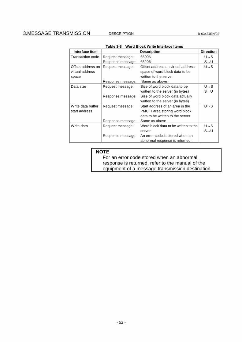
Table 3-8 Word Block Write Interface ItemsInterface item Description Direction
Transaction code Request message: 65006Response message: 65206
U→SS→U
Offset address onvirtual addressspace
Request message: Offset address on virtual addressspace of word block data to bewritten to the server
Response message: Same as above
U→S
Data size Request message: Size of word block data to bewritten to the server (in bytes)
Response message: Size of word block data actuallywritten to the server (in bytes)
U→SS→U
Write data bufferstart address
Request message: Start address of an area in thePMC R area storing word blockdata to be written to the server
Response message: Same as above
U→S
Write data Request message: Word block data to be written to theserver
Response message: An error code is stored when anabnormal response is returned.
U→SS→U
NOTEFor an error code stored when an abnormalresponse is returned, refer to the manual of theequipment of a message transmission destination.

B-63434EN/02 DESCRIPTION 3.MESSAGE TRANSMISSION
- 53 -
3.5 Message Transmission Server Function
3.5.1 Error code list
In response to a request from a client, the message data transmissionserver function automatically returns a response message withoutinvolving the user program. If the message transmission clientreceives an abnormal response, the FANUC FL-net function returns acode listed in Table 3-9.
Table 3-9 List of Server Function Error CodesError code Description
8001h An attempt was made to access a nonexistent PMC area.8002h A specified data size exceeded 1024 bytes.8003h An attempt to allocate a parameter storage area failed.8004h A request was made to write to a write-prohibited area.

3.MESSAGE TRANSMISSION DESCRIPTION B-63434EN/02
- 54 -
3.5.2 Virtual address space allocation
Virtual address space used to read/write byte block and read/writeword block is allocated in the PMC area as described below.
Virtual address space for byte block data
Table 3-10 Virtual Address Space for Byte Block DataAllocation in PMC
Symbol Type of signal Address(decimal)
Virtual addressspace
(hexadecimal)
Remarks
X Signal from machine toPMC
X0000 orlater
0000h or later Read only
Y Signal from PMC tomachine
Y0000 orlater
4000h or later Read only
F Signal from CNC to PMC F0000 orlater
8000h or later Read only
G Signal from PMC to CNC G0000 orlater
C000h or later Read only
R Internal relay R0000 orlater
10000h or later Read/write
D Data table D0000 orlater
14000h or later Read/write
Virtual address space for word block data
Table 3-11 Virtual Address Space for Word Block DataAllocation in PMC
Symbol Type of signal Address(decimal)
Virtual addressspace
(hexadecimal)
Remarks
X Signal from machine toPMC
X0000 orlater
0000h or later Read only
Y Signal from PMC tomachine
Y0000 orlater
2000h or later Read only
F Signal from CNC to PMC F0000 orlater
4000h or later Read only
G Signal from PMC to CNC G0000 orlater
6000h or later Read only
R Internal relay R0000 orlater
8000h or later Read/write
D Data table D0000 orlater
A000h or later Read/write
NOTEOnly installed address space in the PMC can beaccessed. Check PMC address space before use.

B-63434EN/02 DESCRIPTION 3.MESSAGE TRANSMISSION
- 55 -
3.6 Transparent Message Transmission Function
With the FANUC FL-net function, a transparent message of atransaction code (50000 to 59999) can be used as a transparentmessage for data transmission/reception by the user program. Thissection details the interface used for transmission and reception usingthe transparent message transmission function.
3.6.1 Transparent message transmission
Transmission requestmessage
Transmissioncompletion message
7 7
+0 Transmission requestflag
0001h
+0 Completion flag
+2 +2 Request status+3 (Reserved) +3+4 Cancel flag +4+5 Destination node
number+5
+6 (Reserved) +6 (Reserved)+8 Transaction code
50000 to 59999+8 Transaction code
50000 to 59999+10 (Reserved) +10 (Reserved)
+16 Data size +16 Data size
+18 Transmit data bufferstart address
+18 Transmit data bufferstart address
Transparent transmitdata
(Reserved)
�(*+�
�(*"
NOTENote that when the destination node number is set to255, the message is transmitted to all nodes.

3.MESSAGE TRANSMISSION DESCRIPTION B-63434EN/02
- 56 -
Table 3-12 Transparent Transmit Message Interface ItemsInterface item Description Direction
Transaction code !,,,,��)�!4444 U→SData size Size of transparent data to be transmitted (in words) U→STransmit databuffer startaddress
Start address of an area in the PMC R area storingtransparent data to be transmitted
U→S
Transparenttransmit data
Transparent data to be transmitted U→S
B-63434EN/02 DESCRIPTION 3.MESSAGE TRANSMISSION
- 57 -
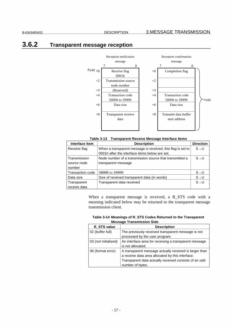
3.6.2 Transparent message reception
Reception notification
message
Reception confirmation
message
7 0 7 0
+0 Receive flag0001h
+0 Completion flag
+2 Transmission sourcenode number
+2
+3 (Reserved) +3+4 Transaction code
50000 to 59999+4 Transaction code
50000 to 59999+6 Data size +6 Data size
+8 Transparent receivedata
+8 Transmit data bufferstart address
Table 3-13 Transparent Receive Message Interface ItemsInterface item Description Direction
Receive flag When a transparent message is received, this flag is set to0001h after the interface items below are set.
S→U
Transmissionsource nodenumber
Node number of a transmission source that transmitted atransparent message
S→U
Transaction code !,,,,��)�!4444 S→UData size Size of received transparent data (in words) S→UTransparentreceive data
Transparent data received S→U
When a transparent message is received, a R_STS code with ameaning indicated below may be returned to the transparent messagetransmission client.
Table 3-14 Meanings of R_STS Codes Returned to the TransparentMessage Transmission Side
R_STS value Description02 (buffer full) The previously received transparent message is not
processed by the user program.03 (not initialized) An interface area for receiving a transparent message
is not allocated.06 (format error) A transparent message actually received is larger than
a receive data area allocated by this interface.Transparent data actually received consists of an oddnumber of bytes.
�(*$�
�(*7

3.MESSAGE TRANSMISSION DESCRIPTION B-63434EN/02
- 58 -
3.7 Server Function of Transmitting a Message withConfirmation
When an ordinary byte block read/write or word block read/writeservice of the message transmission server function is executed, datais exchanged with the client without user-program intervention.Data can also be exchanged with user-program intervention using aspecific virtual address space specification.This specification can be used to establish the concurrency of datatens to hundreds of bytes long easily. In this case, the user programmust transmit a response message, however.This section details the interfaces used for transmission and receptionusing the function of transmitting a message with confirmation.These interfaces use the transmission and reception areas fortransparent message transmission.To perform transmission of a message with confirmation, specify anaddress with an offset of 1000000h in the ordinary virtual addressspace.
3.7.1 Reception of a message with confirmation
�'�<#.�����#.-.'(#.��
��!!(3�
�'�<#.��
'��-. �(#.�����!!(3�
8� � � � � � � � � � � � � � � � � � � + 8� � � � � � � � � � � � � � � � � � � +
<, �&�%?��*(#.
,,,�0
<, )$A(��%)��*(#.
,,,,0
<�� (�!�.!!.���!�� '�
����������
<�
<� :�-�+?�'; <�
< �+#�-#&�%)��&)'�
5!,,���)�5!,,5
< �+#�-#&�%)��&)'�
5!,,���)�5!,,5
<5 �#�#�-%>� <5 �#�#�-%>�
<��--!�#�(�� �!!���
A. #�(1�(�� �!!�!<('�
<��--!�#�(�� �!!���
A. #�(1�(�� �!!�!<('�
<�� <��
�(*$�
�(*7

B-63434EN/02 DESCRIPTION 3.MESSAGE TRANSMISSION
- 59 -
Table 3-1 Receive Message Interface Items
Interface item Description DirectionReceive flag When a message is received, this flag is set
to 0001h after the interface items below areset.
S→U
Transmissionsource nodenumber
Number of the node which transmitted amessage
S→U
Transactioncode
65003 to 65006 S→U
Data size Size of received message data S→U
Virtual addressspace
Offset address on virtual address space S→U
Write data Received write request data S→U
When a message with confirmation is received, an R_STS code with ameaning indicated below may be returned to the message transmissionclient.
Table 3-2 Meanings of R_STS Codes Returned to the Transmission Side of
Transmission of a Message with Confirmation
R_STS value Description02 (buffer full) The previously received message is not processed by
the user program.03 (not initialized) An interface area for receiving a message is not
allocated.06 (format error) A message actually received is larger than a receive
data area allocated by this interface.Word block data actually received consists of an oddnumber of bytes.

3.MESSAGE TRANSMISSION DESCRIPTION B-63434EN/02
- 60 -
3.7.2 Response message transmission
� (�!�.!!.��� �@��!#
��!!(3�
� (�!�.!!.��
'��<1�#.�����!!(3�
8� � � � � � � � � � � � � � � � � � � + 8� � � � � � � � � � � � � � � � � � � +
<,�������������� �� ��� !��
,,,�0
<, )$A(��%)��*(#.
<� <� �D=�-��-�#�=-
<� <�
< #�&�(�*(#. <
<!" ������������� ����# �
<!
<5 :�-�+?�'; <5 :�-�+?�';
<� �+#�-#&�%)��&)'�
5!�,���)�5!�,5
<� �+#�-#&�%)��&)'�
5!�,���)�5!�,5
<�, :�-�+?�'; <�, :�-�+?�';
<���--!�#�(�� �!!���
A. #�(1�(�� �!!�!<('�
<���--!�#�(�� �!!���
A. #�(1�(�� �!!�!<('�
<�5 �#�#�-%>� <�5 �#�#�-%>�
<�� <��
Table 3-3 Response Message Interface Items
Interface item Description DirectionTransactioncode
65203 to 65206 U→S
Virtual addressspace
Offset address on virtual address space U→S
Data size Size of data to be transmitted U→S
Transmit databuffer startaddress
Start address of an area in the PMC R areacontaining data to be transmitted
U→S
Read data Read request data for response U→S
�(*+�
�(*"
NOTEThe procedure for transmission of a message withconfirmation is the same as for the transparentmessage transmission function.

B-63434EN/02 DESCRIPTION 3.MESSAGE TRANSMISSION
- 61 -
3.7.3 Virtual address space allocation
Virtual address space used for byte block read/write and word blockread/write with confirmation is allocated in the PMC area asdescribed below.
Virtual address space for byte block data with confirmation
Table 3-4 Virtual Address Space for Byte Block Data with Confirmation
Allocation in PMCSymbol Type of signal Address
(decimal)
Virtual addressspace
(hexadecimal)
Remarks
X Signal from machineto PMC
X0000 orhigher
01000000h orhigher
Read only
Y Signal from PMC tomachine
Y0000 orhigher
01004000h orhigher
Read only
F Signal from NC toPMC
F0000 orhigher
01008000h orhigher
Read only
G Signal from PMC toNC
G0000 orhigher
0100C000h orhigher
Read only
R Internal relay R0000 orhigher
01010000h orhigher
Read/write
D Data table D0000 orhigher
01014000h orhigher
Read/write
Virtual address space for word block data with confirmation
Table 3-5 Virtual Address Space for Word Block Data with Confirmation
Allocation in PMCSymbol Type of signal Address
(decimal)
Virtual addressspace
(hexadecimal)
Remarks
X Signal from machineto PMC
X0000 orhigher
01000000h orhigher
Read only
Y Signal from PMC tomachine
Y0000 orhigher
01002000h orhigher
Read only
F Signal from NC toPMC
F0000 orhigher
01004000h orhigher
Read only
G Signal from PMC toNC
G0000 orhigher
01006000h orhigher
Read only
R Internal relay R0000 orhigher
01008000h orhigher
Read/write
D Data table D0000 orhigher
0100A000h orhigher
Read/write
NOTEOnly installed address space in the PMC can beaccessed. Check PMC address space before use.

3.MESSAGE TRANSMISSION DESCRIPTION B-63434EN/02
- 62 -
3.8 Byte List of Message Data
The order of data transmission on the network in messagetransmission is related with the byte list in the PMC area as shownbelow.
Byte block data and the PMC area
3"���1()&@�'#�# ���#+�#
8 + 8 +
<,, ��7 <,, ��7
<,� � 7 <,� � 7
<,� !57 <,� !57
<,� ��7 <,� ��7
Word block data and the PMC area
�)+'�1()&@�'#�# ���#+�#
"* + 8 +
<,,,, ��� 7 <,, � 7
<,,,� !5��7 <,� ��7
<,� ��7
<,� !57
Transparent data and the PMC area
�+#�-A#+����'#�# ���#+�#
"* + 8 +
<,,,, ��� 7 <,, � 7
<,,,� !5��7 <,� ��7
<,� ��7
<,� !57
NOTEFL-net word block data and transparent messagedata are 16 bits wide. On the other hand, the datawidth of each address in the PMC area is 8 bits.So, the relationships indicated above apply whendata is exchanged between FL-net messages andthe PMC area.

III. OPERATION

B-63434EN/02 OPERATION 1.PARAMETER SETTING
- 65 -
1 PARAMETER SETTING
This chapter describes the parameters required to operate the FL-netfunction with the Series 16i/18i/21i-A,and with the Power Mate i andthe method of setting the parameters.

1.PARAMETER SETTING OPERATION B-63434EN/02
- 66 -
1.1 Overview
The parameters for the FL-net function are divided into five majorgroups:
(1) Basic parameters(2) State monitoring parameters(3) Area 1 allocation parameters(4) Area 2 allocation parameters(5) Message allocation parameters
Each parameter is detailed below.
(1) Basic parametersTable 1-1 Basic Parameters
Parameter name Description Index numberIP address IP address of the local node
(The host address section of this IP addressis the node number of the local node.)
Pa10
Start address of area1 transmit data
Start address of an area 1 area allocated asDO of the local node
Pa11
Area 1 transmit datasize
Data size of an area 1 area allocated as DOof the local node
Pa12
Start address of area2 transmit data
Start address of an area 2 area allocated asDO of the local node
Pa13
Area 2 transmit datasize
Data size of an area 2 area allocated as DOof the local node
Pa14
Token monitoringtime
Token hold time of the local node Pa15
Allowable minimumframe interval
Inter-frame time interval requested toanother node
Pa16
Node name Equipment name of the local node Pa17
(2) State monitoring parametersTable 1-2 State Monitoring Parameters
Parameter name Description Index numberLocal nodeinformation address
Start address of an area in the PMC R areaused as the output destination of statusinformation about the local node
Pa20
Participating nodeinformation address
Start address of an area in the PMC R areaused as the output destination of a list of allnodes participating in the network
Pa21

B-63434EN/02 OPERATION 1.PARAMETER SETTING
- 67 -
(3) Area 1 allocation parametersTable 1-3 Area 1 Allocation Parameters
Parameter name Description Index numberAllocation address(shared for DI/DO)
Start address of an area in the PMC R areaallocated to area 1
Pa30
Area 1 address(shared for DI/DO)
Start address of area 1 allocated to an areain the PMC R area
Pa31
Data size (shared forDI/DO)
Size of data to be exchanged Pa32
(4) Area 2 allocation parametersTable 1-4 Area 2 Allocation Parameters
Parameter name Description Index numberAllocation address(for DO)
Start address of an area in the PMC R areaor D area that serves as the source of data tobe written to area 2
Pa40
Data size (for DO) Size of data written to area 2 Pa41Allocation address(for DI)
Start address of an area in the PMC R areaor D area that serves as the read destinationof information about other nodes and datafrom area 2
Pa42
Area 2 dataexchange conditionallocation address
Address of an area in the PMC D area that isused to specify conditions on data exchangewith area 2
Pa43
Switch flagallocation address
Flag for switching between specifiedconditions at the area 2 data exchangecondition allocation address above
Pa44
Static area 2 address(for DI)
Start address of static area 2 to be allocatedin the PMC area
Pa45
Static data size(for DI)
Size of data statically exchanged Pa46
(5) Message allocation parametersTable 1-5 Message Allocation Parameters
Parameter name Description Index numberInterface allocationaddress
Start address of an area in the PMC R or Dthat serves as the start address of aninterface used for message transfer
Pa50
Interface allocationsize
Maximum allowable size of the interface areaused above
Pa51
Transparent receivemessage allocationaddress
Start address of an area in the PMC R areaor D area that serves as the start address ofan interface used to store transparentmessage receive data
Pa52
Transparent receivemessage allocationsize
Maximum allowable size of the interface areaused above
Pa53

1.PARAMETER SETTING OPERATION B-63434EN/02
- 68 -
For each FL-net function used, the parameters below need to be set.
A. Cyclic transmission of common memory area 1Basic parametersArea 1 allocation parameters
B. Cyclic transmission of common memory area 2Basic parametersArea 2 allocation parameters
C. Message transmissionBasic parametersMessage allocation parameters
For B (Cyclic transmission of common memory area 2) and C(message transmission) above, operation based on a user programneeds to be performed as required. For information about requiredoperation, see Chapter II DESCRIPTION Section 2.2 and Chapter 3,respectively.
When the state monitoring parameters are set, the user program canmonitor the state of the local node and the network participation stateof other nodes. Perform node state monitoring as required.
CAUTIONInput/output data in common memory area 1 andcommon memory area 2 is transferredasynchronously with ladder program execution. So,the concurrency of input/output data consisting ofmultiple bytes may not be guaranteed. When worddata is input or output, for example depends on thesetting condition, the higher byte may be updatedsome time after the lower byte is updated. Fordetails, see Chapter II DESCRIPTION Section 2.5.
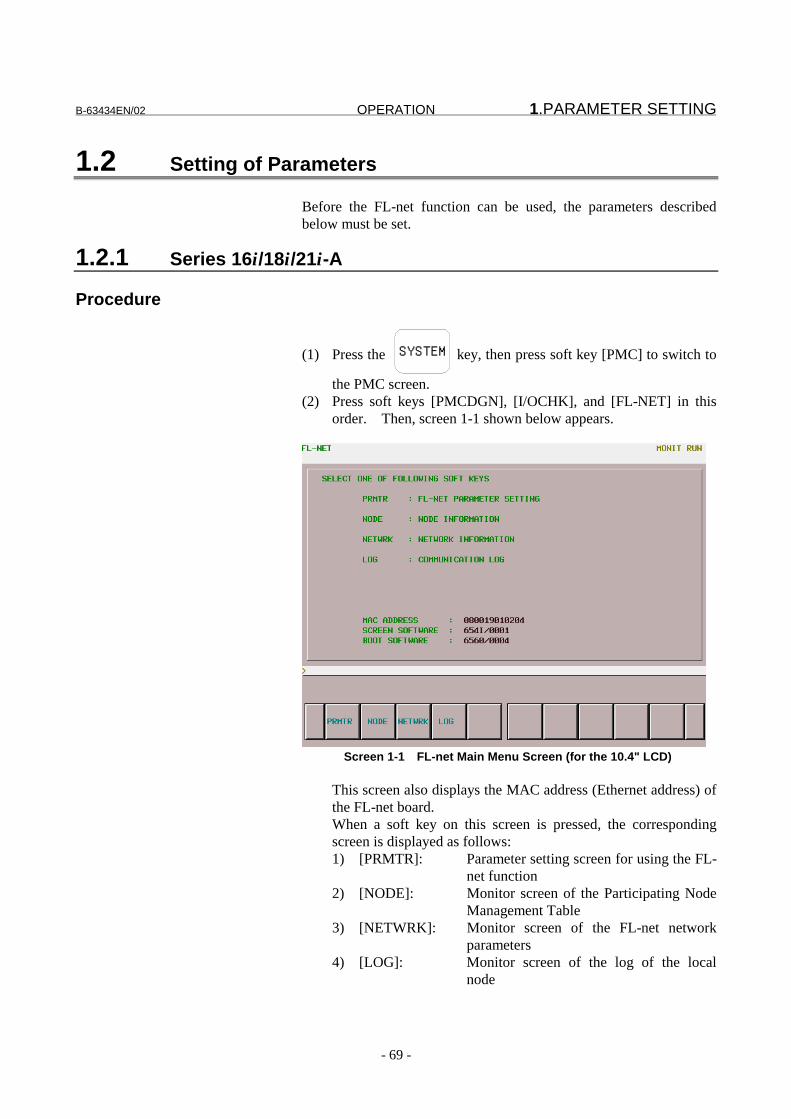
B-63434EN/02 OPERATION 1.PARAMETER SETTING
- 69 -
1.2 Setting of Parameters
Before the FL-net function can be used, the parameters describedbelow must be set.
1.2.1 Series 16i/18i/21i-A
Procedure
(1) Press the SYSTEM key, then press soft key [PMC] to switch to
the PMC screen.(2) Press soft keys [PMCDGN], [I/OCHK], and [FL-NET] in this
order. Then, screen 1-1 shown below appears.
Screen 1-1 FL-net Main Menu Screen (for the 10.4" LCD)
This screen also displays the MAC address (Ethernet address) ofthe FL-net board.When a soft key on this screen is pressed, the correspondingscreen is displayed as follows:1) [PRMTR]: Parameter setting screen for using the FL-
net function2) [NODE]: Monitor screen of the Participating Node
Management Table3) [NETWRK]: Monitor screen of the FL-net network
parameters4) [LOG]: Monitor screen of the log of the local
node

1.PARAMETER SETTING OPERATION B-63434EN/02
- 70 -
(3) Pressing soft key [PRMTR] displays screen 1-2.If data is already registered, the data is displayed.
(4) With the MDI keys and soft keys, enter/update data.
Screen 1-2 FL-net Parameter Setting Screen (for the 10.4" LCD)
(5) Only when a parameter for which "----" is displayed on thescreen above is set, soft key [DISABL] is displayed. Whensuch a parameter is not to be used, press soft key [DISABL].Then, "----" is displayed for the parameter to disable its use.When such a parameter is to be used, enter a desired value aswith other parameters.
CAUTIONWhen a parameter to be allocated to the PMC area isnot to be used, be sure to "disable" the parameter.For example, when 0 is set in OWN STATUS, R0000in the PMC area is assumed to be allocated, and theFL-net board may use an area starting at R0000. Insuch a case, press soft key DISABL so that thesetting becomes "R----."

B-63434EN/02 OPERATION 1.PARAMETER SETTING
- 71 -
Setting item
Each setting item is described below.
Basic parameters
The basic parameters are used to set the FL-net function itself.
Table 1-6 Basic ParametersItem Description
IP ADDRESS
Pa10
IP address of the local node.The host address section (last numeric value) of this IPaddress is the node number of the local node.Only an IP address in class C can be specified.
NODE NAME
Pa17
An arbitrary node name not longer than 10 characters can bespecified.Lowercase letters cannot be displayed and entered.
AREA1 ADDR(Note 1) Pa11
Start address of common memory area 1 of the local node.A value from 0 to 511 can be set.
AREA1 SIZE(Note 1) Pa12
Data size of common memory area 1 of the local node.A value from 0 to 512 can be set.
AREA2 ADDR(Note 1) Pa13
Start address of common memory area 2 of the local node.A value from 0 to 8191 can be set.
AREA2 SIZE(Note 1) Pa14
Data size of common memory area 2 of the local node.A value from 0 to 8192 can be set.
TOKEN WATCH(Note 2)
Pa15
Token monitoring time.Maximum duration of time for which the local node can holdthe token.A value from 1 to 255 can be set. (Unit: ms)
MIN FRAME
Pa16
Minimum allowable frame time interval.A value from 0 to 50 can be specified. (Unit: 100 µs)Set an inter-frame time interval so that the local node canreceive data frames in succession. Usually, set 10 (1 ms).
NOTE1 For common memory area 1, a value beyond 512
must not be specified. For common memory area2, a value beyond 8192 must not be specified.Otherwise, the FL-net function cannot participate inthe network.
2 A token monitoring time is set to reissue a token. Ifthe local node does not issue a token when the timespecified in this parameter has elapsed, the nextnode reissues a token. This means that anadequate value needs to be set in connection withthe amount of transmit data of the local node.Usually, set 50 (50 ms).

1.PARAMETER SETTING OPERATION B-63434EN/02
- 72 -
State monitoring parameters
The state monitoring parameters are used to allocate areas in the PMCarea to which the states of the local node and other nodes are posted.
Table 1-7 State Monitoring ParametersItem Description
OWN STATUS
Pa20
Specify the start address of an area in the PMC R area towhich the communication state of the local node is posted.When this area is not used, set -1, or press soft key [DISABL].This parameter allows only an even address to be set.
ENTRY NODE
Pa21
Specify the start address of an area in the PMC R area towhich the network participation state of other nodes is posted.When this area is not used, set -1, or press soft key [DISABL].This parameter allows only an even address to be set.
Area 1 allocation parameters
The area 1 allocation parameters are used for allocation-relatedsettings to enable data exchange between common memory area 1 andthe PMC R area.
Table 1-8 Area 1 Allocation ParametersItem Description
AREA1 DO/DI:ALLOCATION
Pa30
Start address of an area in the PMC R area used for dataexchange with common memory area 1.This parameter allows only an even address to be set.
AREA1 DO/DI:ADDRESS
Pa31
Start address of an area in common memory area 1 used fordata exchange with the PMC R area.
AREA1 DI/DO:SIZE(Note 1)
Pa32
Size of data exchanged between common memory area 1 andthe PMC R area (Unit: Words).When data exchange between common memory area 1 andthe PMC is not performed, set 0 in this parameter.
NOTE1 The unit of size set in this parameter is words. This
means that for an area used in the PMC R area, thenumber of bytes as many as the size set in thisparameter multiplied by 2 is required.

B-63434EN/02 OPERATION 1.PARAMETER SETTING
- 73 -
Area 2 allocation parameters
The area 2 allocation parameters are used for allocation-relatedsettings to enable data exchange between common memory area 2 andthe PMC R area.
Table 1-9 Area 2 Allocation ParametersItem Description
AREA2 DO:ALLOCATION
Pa40
Start address of an area in the PMC R area or D area used forDO data exchange with common memory area 2.This parameter allows only an even address to be set.
AREA2 DO:SIZE(Note 1)
Pa41
Size of DO data exchanged between common memory area 2and the PMC R area or D area (Unit: Words).When DO data exchange between common memory area 2and the PMC is not performed, set 0 in this parameter.
AREA2 DI:ALLOCATION
Pa42
Start address of an area in the PMC R area or D area used forDI data exchange with common memory area 2.When DI data exchange between common memory area 2and the PMC is not performed, set -1 in this parameter, orpress soft key [DISABL].This parameter allows only an even address to be set.
AREA2 DI:ALLOC PTR(Note 2)
Pa43
Set an area in the PMC R area used to specify a node fromwhich data is to be read as DI data.When DI data exchange between common memory area 2and the PMC is not performed, set -1 in this parameter, orpress soft key [DISABL].This parameter allows only an even address to be set.
AREA2 DI:CHANGE FLG(Note 2)
Pa44
The user can dynamically switch between nodes from whichdata is to be read as DI data.Specify an area in the PMC R area used to specify switchtiming.When dynamic switching is not performed for reading DI data,set -1 in this parameter, or press soft key [DISABL].
AREA2 DI:AREA2 ADDR(Note 2)
Pa45
Start address of common memory area 2 to be staticallyallocated in the PMC area as DI data
AREA2 DI:AREA2 SIZE(Note 1, Note2)
Pa46
Size of DI data statically exchanged between commonmemory area 2 and the PMC area (Unit: Words)
NOTE1 The unit of size set in this parameter is words. This
means that for an area used in the PMC R area, thenumber of bytes as many as the size set in thisparameter multiplied by 2 is required.
2 Parameters AREA2 ADDR and AREA2 SIZE can beused to set a large area for data exchange betweencommon memory area 2 and PMC areaindependently of node numbers.When a value of 0 is set for AREA2 SIZE, no staticallocation is performed and dynamic DI data change

1.PARAMETER SETTING OPERATION B-63434EN/02
- 74 -
is performed for each node.On the other hand, when a value other than 0 is setfor AREA2 SIZE, data starting at AREA2 ADDR incommon memory area 2 is expanded to an area inthe PMC area that is specified by ALLOCATION+4,and dynamic DI data change cannot be performed.In this case, ALLOC PTR and CHANGE FLG areused only for node status information switching.
3 For reasons related to the specifications of theFANUC FL-net board, set the sizes of commonmemory area 1 and area 2 of the local node that areallocated in the PMC area and the sizes of commonmemory area 1 and area 2 of another node that areallocated in the PMC area so that the total size ofthem is 1024 words or less.For example, when 1024 words of common memoryarea 1 and area 2 of the local node are allocated inthe PMC area, DI data of another node cannot beallocated in the PMC area to read it. Conversely,when 1024-word DI data of another node isallocated in the PMC area to read it, DO data of thelocal node cannot be allocated in the PMC area. Insuch a case, take a means such as dynamic changeof the allocated area so that the total size becomes1024 words or less. For details, see Chapter IIDESCRIPTION Section 2.6, "Notes on Allocation inthe PMC Area."
4 Data in the PMC D area is also retained after thepower is turned off, then on again. For this reason,be careful to use the PMC D area. Clear the PMCD area to 0 using the user program immediately afterpower-on as required.

B-63434EN/02 OPERATION 1.PARAMETER SETTING
- 75 -
Message allocation parameters
The message allocation parameters are used to allocate a messagetransmit interface area in the PMC R area.
Table 1-10 Message Allocation ParametersItem Description
MESSAGE:ADDRESS
Pa50
Start address of an interface area in the PMC R area or D areaused when the message transmission client function is used.This parameter allows only an even address to be set.
MESSAGE:SIZE
Pa51
Size of the interface area above (Unit: Bytes).When the message transmission client function is not used,set 0 in this parameter.
MESSAGE:RECV MSG
Pa52
Start address of an interface area in the PMC R area or D areaused for transparent message receive data.This parameter allows only an even address to be set.
MESSAGE:SIZE
Pa53
Size of the interface area above (Unit: Bytes).When transparent message receive data is not accepted, set0 in this parameter.

1.PARAMETER SETTING OPERATION B-63434EN/02
- 76 -
Basic method of parameter input
The basic method of parameter input is described below.
Procedure
(1) Set the CNC mode to the MDI mode.(2) Display the parameter setting screen of screen 1-2.(3) With the cursor keys, move the cursor to a desired item.(4) Enter a desired parameter value with the MDI keys.(5) Execute the input of the parameter by pressing soft key [INPUT]
or function key INPUT .
Example of input
Setting 192.168.250.10 in IP ADDRESSFor the sample screen below, the 9.5" LCD is used.
(A) Move the cursor to IP ADDRESS.
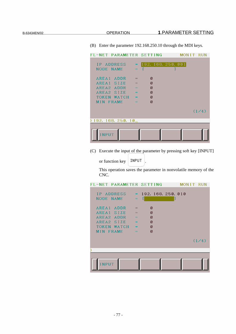
B-63434EN/02 OPERATION 1.PARAMETER SETTING
- 77 -
(B) Enter the parameter 192.168.250.10 through the MDI keys.
(C) Execute the input of the parameter by pressing soft key [INPUT]
or function key INPUT .
This operation saves the parameter in nonvolatile memory of theCNC.
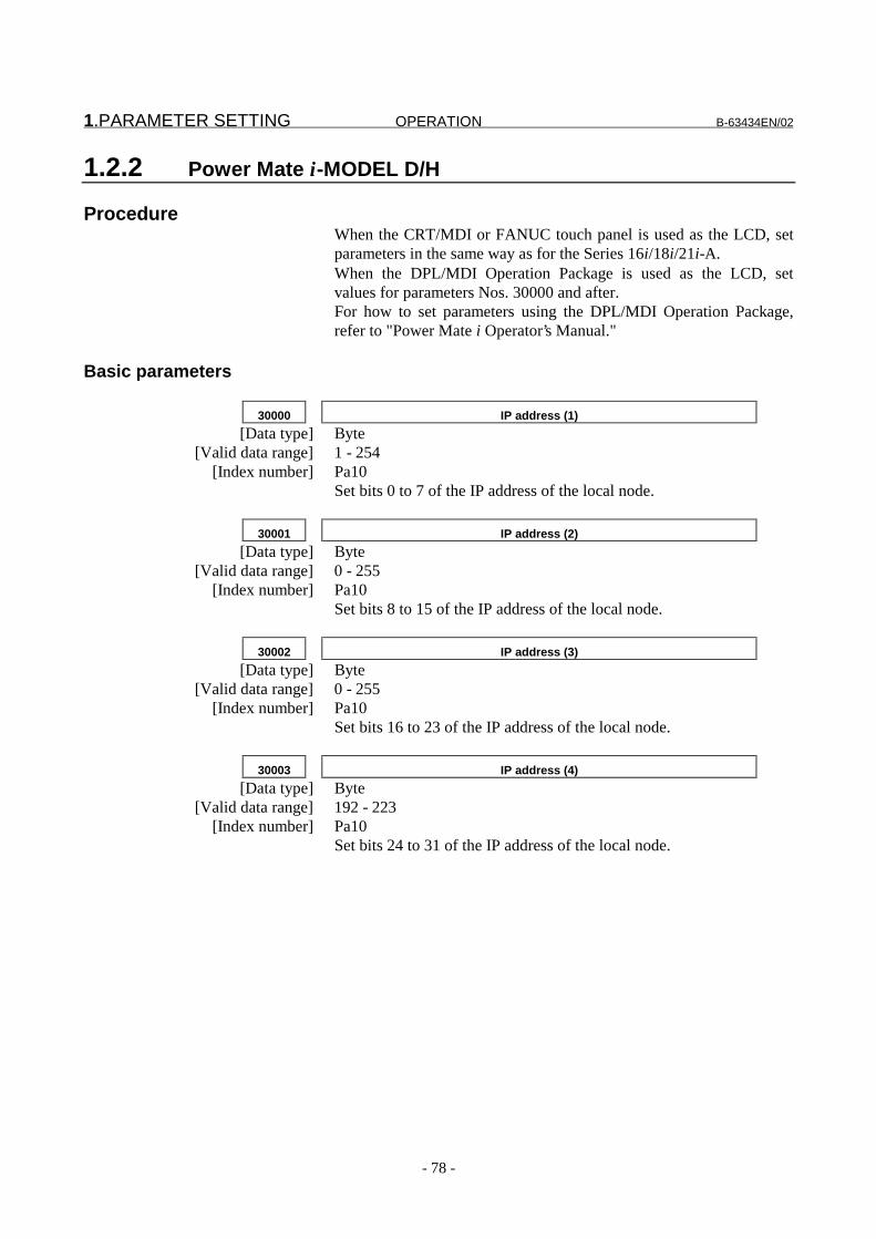
1.PARAMETER SETTING OPERATION B-63434EN/02
- 78 -
1.2.2 Power Mate i-MODEL D/H
ProcedureWhen the CRT/MDI or FANUC touch panel is used as the LCD, setparameters in the same way as for the Series 16i/18i/21i-A.When the DPL/MDI Operation Package is used as the LCD, setvalues for parameters Nos. 30000 and after.For how to set parameters using the DPL/MDI Operation Package,refer to "Power Mate i Operator’s Manual."
Basic parameters
30000 IP address (1)
[Data type] Byte[Valid data range] 1 - 254
[Index number] Pa10Set bits 0 to 7 of the IP address of the local node.
30001 IP address (2)
[Data type] Byte[Valid data range] 0 - 255
[Index number] Pa10Set bits 8 to 15 of the IP address of the local node.
30002 IP address (3)
[Data type] Byte[Valid data range] 0 - 255
[Index number] Pa10Set bits 16 to 23 of the IP address of the local node.
30003 IP address (4)
[Data type] Byte[Valid data range] 192 - 223
[Index number] Pa10Set bits 24 to 31 of the IP address of the local node.

B-63434EN/02 OPERATION 1.PARAMETER SETTING
- 79 -
30010 Node name: 1st character
30011 Node name: 2nd character
30012 Node name: 3rd character
30013 Node name: 4th character
30014 Node name: 5th character
30015 Node name: 6th character
30016 Node name: 7th character
30017 Node name: 8th character
30018 Node name: 9th character
30019 Node name: 10th character
[Data type] Byte[Index number] Pa17
Set the equipment name of the local node one character for eachparameter in ASCII code.
30020 Start address of area 1 transmit data
[Data type] Word[Valid data range] 0 - 511
[Index number] Pa11
30021 Area 1 transmit data size
[Data type] Word[Valid data range] 0 - 512
[Index number] Pa12
30022 Start address of area 2 transmit data
[Data type] Word[Valid data range] 0 - 8191
[Index number] Pa13
30023 Area 2 transmit data size
[Data type] Word[Valid data range] 0 - 8192
[Index number] Pa14
30024 Token monitoring time
[Data type] Byte[Unit of data] 1 msec
[Valid data range] 1 - 255[Index number] Pa15
30025 Minimum allowable frame interval
[Data type] Byte[Unit of data] 100 μsec

1.PARAMETER SETTING OPERATION B-63434EN/02
- 80 -
[Valid data range] 0 - 50[Index number] Pa16
State monitoring parameters
30026 Local node informatino address
[Data type] Word[Valid data range] 0 - (only an even address)
[Index number] Pa20
30027 Participating node information address
[Data type] Byte[Valid data range] 0 - (only an even address)
[Index number] Pa21
Area 1 allocation parameters
30030 Allocation address (shared for DI/DO)
[Data type] Word[Valid data range] 0 - (only an even address)
[Index number] Pa30
30031 Area 1 address (shared for DI/DO)
[Data type] Word[Valid data range] 0 - 511
[Index number] Pa31
30032 Data size (shared for DI/DO)
[Data type] Word[Valid data range] 0 - 512
[Index number] Pa32
Area 2 allocation parameters
30033 Allocation address (for DO)
[Data type] Word[Valid data range] 0 - (only an even address)
[Index number] Pa40
30034 Data size (for DO)
[Data type] Word[Valid data range] 0 - 8192
[Index number] Pa41
30035 Allocation address (for DI)
[Data type] Word[Valid data range] 0 - (only an even address)
[Index number] Pa42
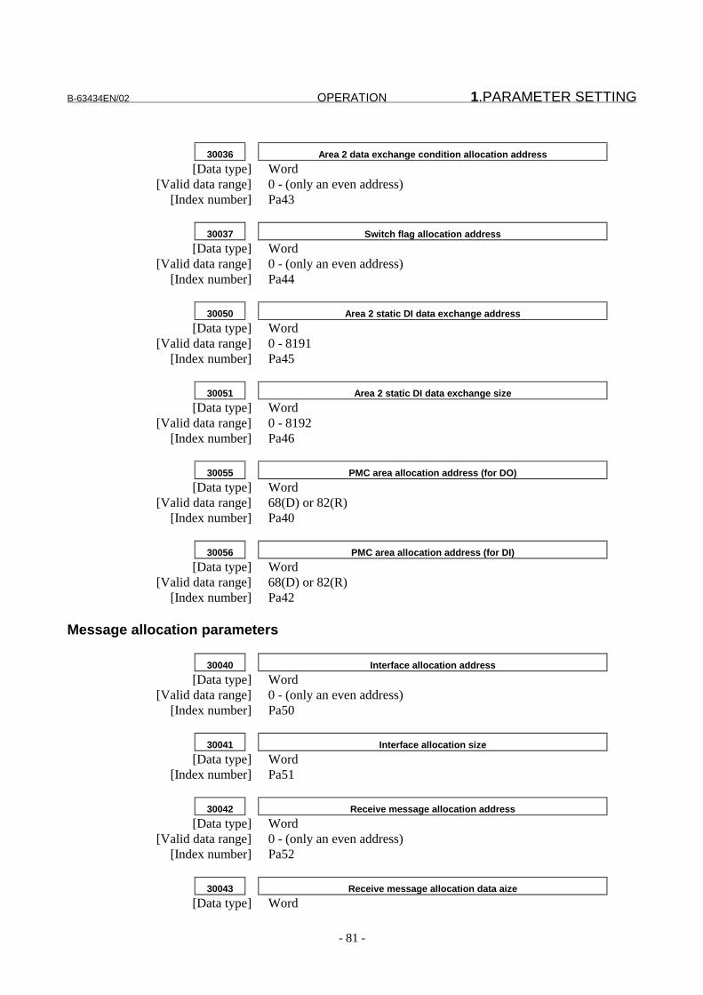
B-63434EN/02 OPERATION 1.PARAMETER SETTING
- 81 -
30036 Area 2 data exchange condition allocation address
[Data type] Word[Valid data range] 0 - (only an even address)
[Index number] Pa43
30037 Switch flag allocation address
[Data type] Word[Valid data range] 0 - (only an even address)
[Index number] Pa44
30050 Area 2 static DI data exchange address
[Data type] Word[Valid data range] 0 - 8191
[Index number] Pa45
30051 Area 2 static DI data exchange size
[Data type] Word[Valid data range] 0 - 8192
[Index number] Pa46
30055 PMC area allocation address (for DO)
[Data type] Word[Valid data range] 68(D) or 82(R)
[Index number] Pa40
30056 PMC area allocation address (for DI)
[Data type] Word[Valid data range] 68(D) or 82(R)
[Index number] Pa42
Message allocation parameters
30040 Interface allocation address
[Data type] Word[Valid data range] 0 - (only an even address)
[Index number] Pa50
30041 Interface allocation size
[Data type] Word[Index number] Pa51
30042 Receive message allocation address
[Data type] Word[Valid data range] 0 - (only an even address)
[Index number] Pa52
30043 Receive message allocation data aize
[Data type] Word
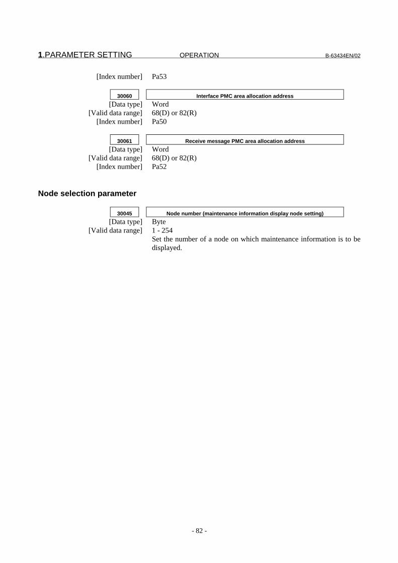
1.PARAMETER SETTING OPERATION B-63434EN/02
- 82 -
[Index number] Pa53
30060 Interface PMC area allocation address
[Data type] Word[Valid data range] 68(D) or 82(R)
[Index number] Pa50
30061 Receive message PMC area allocation address
[Data type] Word[Valid data range] 68(D) or 82(R)
[Index number] Pa52
Node selection parameter
30045 Node number (maintenance information display node setting)
[Data type] Byte[Valid data range] 1 - 254
Set the number of a node on which maintenance information is to bedisplayed.

B-63434EN/02 OPERATION 2.MAINTENANCE SCREEN
- 83 -
2 MAINTENANCE SCREEN
This chapter describes the screens used for maintenance of the FL-netfunction with the Series 16i/18i/21i-A and with the Power Mate i.

2.MAINTENANCE SCREEN OPERATION B-63434EN/02
- 84 -
2.1 Participating Node Management Table
The FL-net participating node monitor screen allows the user toreference the parameters of each node participating in the FL-netnetwork.
Procedure
(1) Press function key SYSTEM , then press soft key [PMC] to
switch to the PMC screen.(2) Press soft keys [PMCDGN], [I/OCHK], and [FL-NET] in this
order. Then, screen 1-1 appears.(3) On screen 1-1, press soft key [NODE]. Then, screen 2-1 shown
below appears.
Screen 2-1 FL-net Participating Node Monitor Screen (10.4" LCD)
(4) In the upper part of the screen, a list of nodes participating in thenetwork can be monitored. A node participating in the networkhas its node number marked with O. (An asterisk (*) isindicated for the local node.) On the screen above, nodes 10and nodes 85 are participating in the network, and the local nodeis node 10.
(5) When a soft key displayed on the screen is pressed, thecorresponding operation is performed as follows:1) [NODE]: Displays the parameters of a specified node.2) [P.NODE]: Displays the parameters of the node
immediately before the currently displayednode.

B-63434EN/02 OPERATION 2.MAINTENANCE SCREEN
- 85 -
3) [N.NODE]: Displays the parameters of the nodeimmediately after the currently displayednode.
(6) When this screen is displayed, the information about the localnode is first displayed.
(7) When the 9.5" LCD is used, all information cannot be displayedon one screen. So, two screens are used as shown below. Onescreen is used to monitor participating nodes, and the other isused to monitor the parameters of each node.
Screen 2-2 FL-net Participating Node Monitor Screen (9.5" LCD)
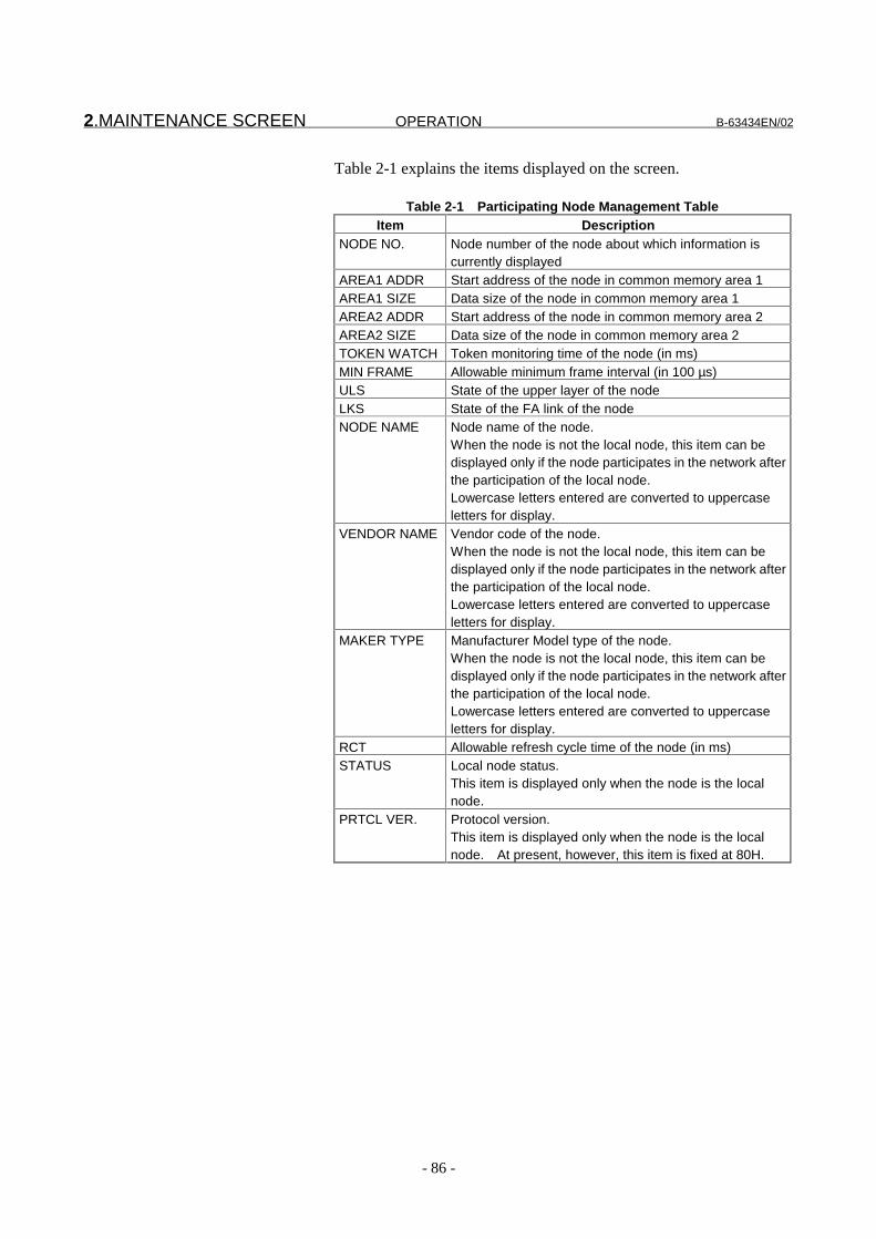
2.MAINTENANCE SCREEN OPERATION B-63434EN/02
- 86 -
Table 2-1 explains the items displayed on the screen.
Table 2-1 Participating Node Management TableItem Description
NODE NO. Node number of the node about which information iscurrently displayed
AREA1 ADDR Start address of the node in common memory area 1AREA1 SIZE Data size of the node in common memory area 1AREA2 ADDR Start address of the node in common memory area 2AREA2 SIZE Data size of the node in common memory area 2TOKEN WATCH Token monitoring time of the node (in ms)MIN FRAME Allowable minimum frame interval (in 100 µs)ULS State of the upper layer of the nodeLKS State of the FA link of the nodeNODE NAME Node name of the node.
When the node is not the local node, this item can bedisplayed only if the node participates in the network afterthe participation of the local node.Lowercase letters entered are converted to uppercaseletters for display.
VENDOR NAME Vendor code of the node.When the node is not the local node, this item can bedisplayed only if the node participates in the network afterthe participation of the local node.Lowercase letters entered are converted to uppercaseletters for display.
MAKER TYPE Manufacturer Model type of the node.When the node is not the local node, this item can bedisplayed only if the node participates in the network afterthe participation of the local node.Lowercase letters entered are converted to uppercaseletters for display.
RCT Allowable refresh cycle time of the node (in ms)STATUS Local node status.
This item is displayed only when the node is the localnode.
PRTCL VER. Protocol version.This item is displayed only when the node is the localnode. At present, however, this item is fixed at 80H.

B-63434EN/02 OPERATION 2.MAINTENANCE SCREEN
- 87 -
2.2 Network Management Table
The FL-net network management table screen allows the user toreference the parameters of each node in the FL-net networkmanagement table.
Procedure
(1) Press function key SYSTEM , then press soft key [PMC] to
switch to the PMC screen.(2) Press soft keys [PMCDGN], [I/OCHK], and [FL-NET] in this
order. Then, screen 1-1 appears.(3) On screen 1-1, press soft key [NETWRK]. Then, screen 2-3
shown below appears.
Screen 2-3 FL-net Network Management Table Screen (10.4" LCD)

2.MAINTENANCE SCREEN OPERATION B-63434EN/02
- 88 -
Table 2-2 explains the items displayed on the screen.
Table 2-2 Network Management TableItem Description
TOKEN NODE Node number of the node that currently holds the tokenMIN FRAME Maximum value of the allowable minimum frame intervals
of all nodes participating in the network (in 100 µs)RCT Allowable refresh cycle time of the local node (in ms)RCM Refresh cycle measurement time of the local node
(in ms)MAX RCM Maximum refresh cycle measurement time of the local
node (in ms)MIN RCM Minimum refresh cycle measurement time of the local
node (in ms)

B-63434EN/02 OPERATION 2.MAINTENANCE SCREEN
- 89 -
2.3 Log Information Management Table
The FL-net log information management table screen allows the userto reference the network log information of the local node.
Procedure
(1) Press function key SYSTEM , then press soft key [PMC] to
switch to the PMC screen.(2) Press soft keys [PMCDGN], [I/OCHK], and [FL-NET] in this
order. Then, screen 1-1 appears.(3) On screen 1-1, press soft key [LOG]. Then, screen 2-4 shown
below appears.
Screen 2-4 FL-net Log Information Management Table Screen(10.4" LCD)
(4) Pressing soft key [CLEAR] clears log information.

2.MAINTENANCE SCREEN OPERATION B-63434EN/02
- 90 -
Table 2-3 explains the items displayed on the screen.
Table 2-3 Log Information Management TableItem Description
TOTAL SEND COUNT SEND Number of transmitted framesSEND ERROR COUNT SERR Number of transmission errorsTOTAL RECEIVE COUNT RECV Number of received framesRECEIVE ERROR COUNT RERR Number of receive errors.
The reception of a packet other thanFL-net packets is also counted as areceive error.
CYCLIC DATA ERRORCOUNT
RCYC Number of errors in cyclictransmission
MESSAGE RETRY COUNT RMSG Number of retrials for messagetransmission
MESSAGE RETRY OVERCOUNT
MOVR Number of operations where retrialsfor message transmissionexceeded an allowable number ofretrials
MESSAGE RECEIVEERROR COUNT
MRCV Number of receive message errors
ACK ERROR COUNT ACKE Number of ACK errorsDUPLICATED TOKENCOUNT
TDUP Number of duplicate tokensdetected
DESTROYED TOKENCOUNT
TDES Number of token discard operations
TOKEN COUNT TKNC Number of token reissue operationsFRAME WAIT COUNT FRMW Number of frame wait states
entered because there are no othernodes in the network
ENTRY COUNT ENTR Number of network participationoperations performed by the localnode
OWN DISCONNECTCOUNT
DISC Number of disconnections of thelocal node due to token hold time-out
SKIP DISCONNECTCOUNT
SKIP Number of disconnections of thelocal node because the token is notpassed to the local node
OTHER NODEDISCONNECT COUNT
OTHE Number of recognitions that othernodes are disconnected

B-63434EN/02 OPERATION 2.MAINTENANCE SCREEN
- 91 -
When the 9.5" LCD is used, the name of each item is limited to fourcharacters as shown below.
Screen 2-5 FL-net Log Information Management Table Screen(9.5" LCD)
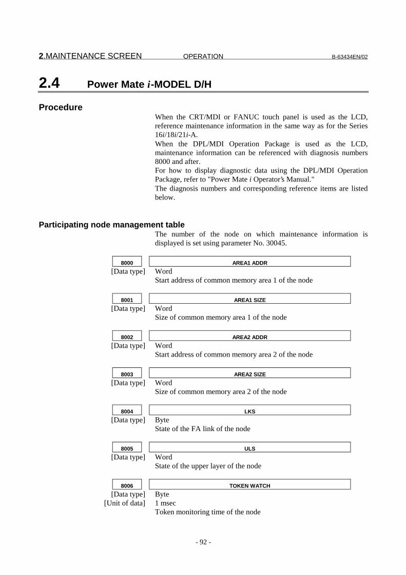
2.MAINTENANCE SCREEN OPERATION B-63434EN/02
- 92 -
2.4 Power Mate i-MODEL D/H
ProcedureWhen the CRT/MDI or FANUC touch panel is used as the LCD,reference maintenance information in the same way as for the Series16i/18i/21i-A.When the DPL/MDI Operation Package is used as the LCD,maintenance information can be referenced with diagnosis numbers8000 and after.For how to display diagnostic data using the DPL/MDI OperationPackage, refer to "Power Mate i Operator’s Manual."The diagnosis numbers and corresponding reference items are listedbelow.
Participating node management tableThe number of the node on which maintenance information isdisplayed is set using parameter No. 30045.
8000 AREA1 ADDR
[Data type] WordStart address of common memory area 1 of the node
8001 AREA1 SIZE
[Data type] WordSize of common memory area 1 of the node
8002 AREA2 ADDR
[Data type] WordStart address of common memory area 2 of the node
8003 AREA2 SIZE
[Data type] WordSize of common memory area 2 of the node
8004 LKS
[Data type] ByteState of the FA link of the node
8005 ULS
[Data type] WordState of the upper layer of the node
8006 TOKEN WATCH
[Data type] Byte[Unit of data] 1 msec
Token monitoring time of the node
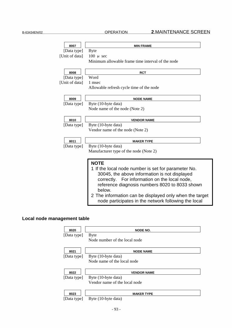
B-63434EN/02 OPERATION 2.MAINTENANCE SCREEN
- 93 -
8007 MIN FRAME
[Data type] Byte[Unit of data] 100 μsec
Minimum allowable frame time interval of the node
8008 RCT
[Data type] Word[Unit of data] 1 msec
Allowable refresh cycle time of the node
8009 NODE NAME
[Data type] Byte (10-byte data)Node name of the node (Note 2)
8010 VENDOR NAME
[Data type] Byte (10-byte data)Vendor name of the node (Note 2)
8011 MAKER TYPE
[Data type] Byte (10-byte data)Manufacturer type of the node (Note 2)
Local node management table
8020 NODE NO.
[Data type] ByteNode number of the local node
8021 NODE NAME
[Data type] Byte (10-byte data)Node name of the local node
8022 VENDOR NAME
[Data type] Byte (10-byte data)Vendor name of the local node
8023 MAKER TYPE
[Data type] Byte (10-byte data)
NOTE1 If the local node number is set for parameter No.
30045, the above information is not displayedcorrectly. For information on the local node,reference diagnosis numbers 8020 to 8033 shownbelow.
2 The information can be displayed only when the targetnode participates in the network following the local

2.MAINTENANCE SCREEN OPERATION B-63434EN/02
- 94 -
Manufacturer type of the local node
8024 STATUS
[Data type] ByteStatus of the local node
8025 LKS
[Data type] ByteState of the FA link of the local node
8026 ULS
[Data type] WordState of the upper layer of the local node
8027 AREA1 ADDR
[Data type] WordStart address of common memory area 1 of the local node
8028 AREA1 SIZE
[Data type] WordSize of common memory area 1 of the local node
8029 AREA2 ADDR
[Data type] WordStart address of common memory area 2 of the local node
8030 AREA2 SIZE
[Data type] WordSize of common memory area 2 of the local node
8031 TOKEN WATCH
[Data type] Byte[Unit of data] 1 msec
Token monitoring time of the local node
8032 MIN FRAME
[Data type] Byte[Unit of data] 100 μsec
Minimum allowable frame time interval of the local node
8033 PRTCL VER.
[Data type] ByteProtocol version
Network management table
8040 TOKEN NODE
[Data type] Byte
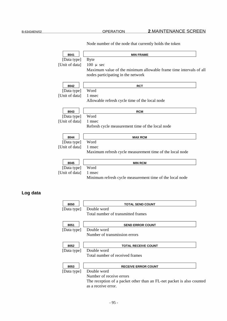
B-63434EN/02 OPERATION 2.MAINTENANCE SCREEN
- 95 -
Node number of the node that currently holds the token
8041 MIN FRAME
[Data type] Byte[Unit of data] 100 μsec
Maximum value of the minimum allowable frame time intervals of allnodes participating in the network
8042 RCT
[Data type] Word[Unit of data] 1 msec
Allowable refresh cycle time of the local node
8043 RCM
[Data type] Word[Unit of data] 1 msec
Refresh cycle measurement time of the local node
8044 MAX RCM
[Data type] Word[Unit of data] 1 msec
Maximum refresh cycle measurement time of the local node
8045 MIN RCM
[Data type] Word[Unit of data] 1 msec
Minimum refresh cycle measurement time of the local node
Log data
8050 TOTAL SEND COUNT
[Data type] Double wordTotal number of transmitted frames
8051 SEND ERROR COUNT
[Data type] Double wordNumber of transmission errors
8052 TOTAL RECEIVE COUNT
[Data type] Double wordTotal number of received frames
8053 RECEIVE ERROR COUNT
[Data type] Double wordNumber of receive errorsThe reception of a packet other than an FL-net packet is also countedas a receive error.

2.MAINTENANCE SCREEN OPERATION B-63434EN/02
- 96 -
8054 CYCLIC DATA ERROR COUNT
[Data type] Double wordNumber of errors in cyclic transmission
8055 MESSAGE RETRY COUNT
[Data type] Double wordNumber of retrials for message transmission
8056 MESSAGE RETRY OVER COUNT
[Data type] Double wordNumber of operations where retrials for message transmissionexceeded the maximum number
8057 MESSAGE RECEIVE ERROR COUNT
[Data type] Double wordNumber of receive message errors
8058 ACK ERROR COUNT
[Data type] Double wordNumber of ACK data errors
8059 DUPLICATED TOKEN COUNT
[Data type] Double wordNumber of duplicate tokens detected
8060 DESTROYED TOKEN COUNT
[Data type] Double wordNumber of token discard operations
8061 TOKEN COUNT
[Data type] Double wordNumber of token reissue operations
8062 FRAME WAIT COUNT
[Data type] Double wordNumber of frame wait states entered because there are no other nodesin the network
8063 ENTRY COUNT
[Data type] Double wordNumber of network participation operations performed by the localnode
8064 OWN DISCONNECT COUNT
[Data type] Double wordNumber of disconnections of the local node from the network due to atoken hold time-out
8065 SKIP DISCONNECT COUNT

B-63434EN/02 OPERATION 2.MAINTENANCE SCREEN
- 97 -
[Data type] Double wordNumber of disconnections of the local node from the network becausethe token is not passed to the local node
8066 OTHER NODE DISCONNECT COUNT
[Data type] Double wordNumber of recognitions that other nodes are disconnected from thenetwork

3.EXAMPLE OF CONNECTION OPERATION B-63434EN/02
- 98 -
3 EXAMPLE OF CONNECTION
This chapter describes an example of connection using the FL-netfunction with the Series 16i/18i/21i-A with the Power Mate i.

B-63434EN/02 OPERATION 3.EXAMPLE OF CONNECTION
- 99 -
3.1 Example of Configuration
Using the example of configuration shown below, this sectiondescribes the setting of each parameter.
Ethernet
Series 16i -A Series 18i -A Power Mate i -D
Node No.10 Node No.20 Node No.30
Fig. 3-1 Example of FL-net Configuration
The parameter settings and PMC area allocation state when 4-wordDO data in common memory area 1 and 64-word DO data in commonmemory area 2 are exchanged at all of the three nodes are describedbelow.
The common memory of each node is allocated as shown below.
Common memory area1
Common memory area2
0x0000 0x0000 Node No. 100x0010 Node No. 100x0014 Node No. 20 0x0040
0x0018 Node No. 30 0x0050 Node No. 200x001c
0x0090
0x00a0 Node No. 30
0x00d0
0x01ff
0x1fff
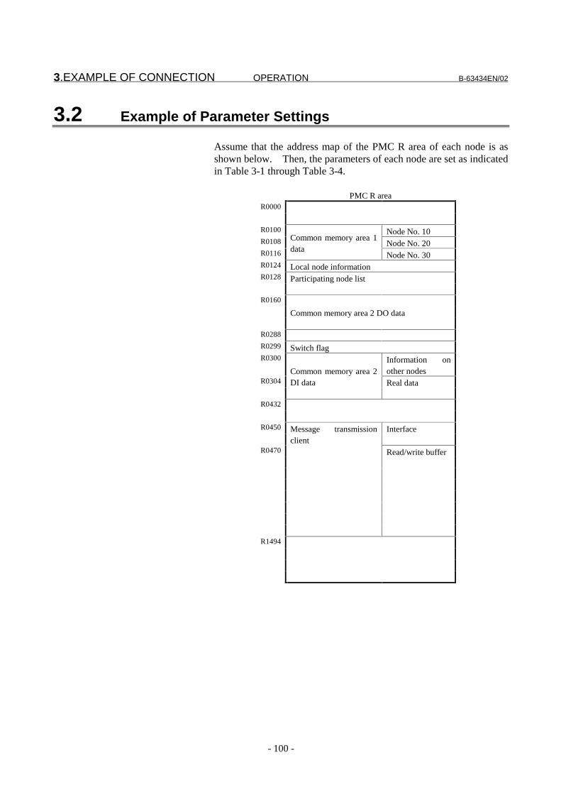
3.EXAMPLE OF CONNECTION OPERATION B-63434EN/02
- 100 -
3.2 Example of Parameter Settings
Assume that the address map of the PMC R area of each node is asshown below. Then, the parameters of each node are set as indicatedin Table 3-1 through Table 3-4.
PMC R areaR0000
R0100 Node No. 10R0108 Node No. 20R0116
Common memory area 1data
Node No. 30R0124 Local node informationR0128 Participating node list
R0160
Common memory area 2 DO data
R0288
R0299 Switch flagR0300 Information on
other nodesR0304 Real data
Common memory area 2DI data
R0432
R0450 InterfaceMessage transmissionclient
R0470 Read/write buffer
R1494

B-63434EN/02 OPERATION 3.EXAMPLE OF CONNECTION
- 101 -
Table 3-1 Parameters of Node No. 10Item Setting Item Setting
IP ADDRESS 192.168.250.10 AREA2 DI: -NODE NAME NODE#10 ALLOCATION R0300AREA1 ADDR 16 ALLOC PTR D0000AREA1 SIZE 4 CHANGE FLG R0299AREA2 ADDR 0 AREA2 ADDR 0AREA2 SIZE 64 AREA2 SIZE 0TOKEN WATCH 50 MESSAGE: -MIN FRAME 10 ADDRESS R0450OWN STATUS R0124 SIZE 20ENTRY NODE R0128 RECV MSG R0000AREA1 DO/DI: - SIZE 0ALLOCATION R0100ADDRESS 16SIZE 12 D0000 of PMC 20AREA2 DO: - D0002 of PMC 0ALLOCATION R0160 D0004 of PMC 64SIZE 64 D0006 of PMC 0
Table 3-2 Parameters of Node No. 20Item Setting Item Setting
IP ADDRESS 192.168.250.20 AREA2 DI: -NODE NAME NODE#20 ALLOCATION R0300AREA1 ADDR 20 ALLOC PTR D0000AREA1 SIZE 4 CHANGE FLG R0299AREA2 ADDR 80 AREA2 ADDR 0AREA2 SIZE 64 AREA2 SIZE 0TOKEN WATCH 50 MESSAGE: -MIN FRAME 10 ADDRESS R0450OWN STATUS R0124 SIZE 20ENTRY NODE R0128 RECV MSG R0000AREA1 DO/DI: - SIZE 0ALLOCATION R0100ADDRESS 16SIZE 12 D0000 of PMC 30AREA2 DO: - D0002 of PMC 0ALLOCATION R0160 D0004 of PMC 64SIZE 64 D0006 of PMC 0

3.EXAMPLE OF CONNECTION OPERATION B-63434EN/02
- 102 -
Table 3-3 Parameters of Node No. 30 (CRT/MDI)Item Setting Item Setting
IP ADDRESS 192.168.250.30 AREA2 DI: -NODE NAME NODE#30 ALLOCATION R0300AREA1 ADDR 24 ALLOC PTR D0000AREA1 SIZE 4 CHANGE FLG R0299AREA2 ADDR 160 AREA2 ADDR 0AREA2 SIZE 64 AREA2 SIZE 0TOKEN WATCH 50 MESSAGE: -MIN FRAME 10 ADDRESS R0450OWN STATUS R0124 SIZE 20ENTRY NODE R0128 RECV MSG R0000AREA1 DO/DI: - SIZE 0ALLOCATION R0100ADDRESS 16SIZE 12 D0000 of PMC 10AREA2 DO: - D0002 of PMC 0ALLOCATION R0160 D0004 of PMC 64SIZE 64 D0006 of PMC 0
Table 3-4 Parameters of Node No. 30 (DPL/MDI)Item Setting Item Setting
No.30000 30 No.30030 100No.30001 250 No.30031 16No.30002 168 No.30032 12No.30003 192 No.30033 160No.30010 78 No.30034 64No.30011 79 No.30035 300No.30012 68 No.30036 0No.30013 69 No.30037 299No.30014 35 No.30040 450No.30015 51 No.30041 20No.30016 48 No.30042 0No.30017 0 No.30043 0No.30018 0 No.30050 0No.30019 0 No.30051 0No.30020 24 No.30055 82No.30021 4 No.30056 82No.30022 160 No.30060 82No.30023 64 No.30061 82No.30024 50 D0000 of PMC 10No.30025 10 D0002 of PMC 0No.30026 124 D0004 of PMC 64No.30027 128 D0006 of PMC 0

B-63434EN/02 OPERATION 3.EXAMPLE OF CONNECTION
- 103 -
3.3 Image of Data Exchange
When data exchange is performed with the examples of configurationand parameter settings described earlier, the illustration below showshow the data of each node is viewed in the PMC R area of each node.
Node No. 10 Node No. 20 Node No. 30R0000 R0000 R0000
R0100#10
R0100#10
R0100#10
R0108Area 1 #20
R0108Area 1 #20
R0108Area 1 #20
R0116#30
R0116#30
R0116#30
R0160Area 2 DO
R0160Area 2 DO
R0160Area 2 DO
R0304Area 2 DI
R0304Area 2 DI
R0304Area 2 DI
Moreover, a message can be transmitted using a PMC area starting atR0450.


IV. CONNECTION


B-63434EN/02 CONNECTION 1.INSTALLATION
- 107 -
1 INSTALLATION
This chapter provides information required for installation of the FL-net board.
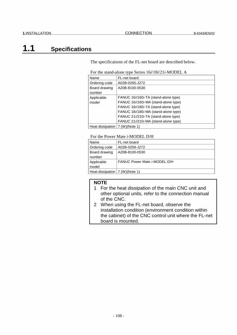
1.INSTALLATION CONNECTION B-63434EN/02
- 108 -
1.1 Specifications
The specifications of the FL-net board are described below.
For the stand-alone type Series 16i/18i/21i-MODEL AName FL-net boardOrdering code A02B-0265-J272Board drawingnumber
A20B-8100-0530
Applicablemodel
FANUC 16i/160i-TA (stand-alone type)FANUC 16i/160i-MA (stand-alone type)FANUC 18i/180i-TA (stand-alone type)FANUC 18i/180i-MA (stand-alone type)FANUC 21i/210i-TA (stand-alone type)FANUC 21i/210i-MA (stand-alone type)
Heat dissipation 7 (W)(Note 1)
For the Power Mate i-MODEL D/HName FL-net boardOrdering code A02B-0259-J272Board drawingnumber
A20B-8100-0530
Applicablemodel
FANUC Power Mate i-MODEL D/H
Heat dissipation 7 (W)(Note 1)
NOTE1 For the heat dissipation of the main CNC unit and
other optional units, refer to the connection manualof the CNC.
2 When using the FL-net board, observe theinstallation condition (environment condition withinthe cabinet) of the CNC control unit where the FL-netboard is mounted.

B-63434EN/02 CONNECTION 1.INSTALLATION
- 109 -
1.2 Installation
This section describes information about the installation of the FL-netboard.
The FL-net board can be installed in any mini-slot of a one-slot orthree-slot basic unit.
CD38N

2.CONNECTION OF THE COMMUNICATION FUNCTION CONNECTION B-63434EN/02
- 110 -
2 CONNECTION OF THECOMMUNICATION FUNCTION
This chapter provides information required for Ethernet connection ofthe FL-net board.
CAUTION1 Before attaching or detaching a cable to the FL-net
board, turn off the power to the CNC, and confirmthat the power is off.
2 For network building and the condition for usingdevices other than the FL-net board (such as mediaconverters, hubs, transceivers, and cables), contactthe supplier of each device. For networkinstallation, care must be taken to protect thenetwork from a noise source. Separate the networkwiring sufficiently away from a noise source such asa power line and motor from an electrical viewpoint,and ground each device as required. If grounding isinsufficient because of high impedance, acommunication error may occur. Before going intoactual operation after equipment installation, checkthe operation by conducting a communication test.FANUC cannot take responsibility for network troublearising from a device other than the FL-net board.
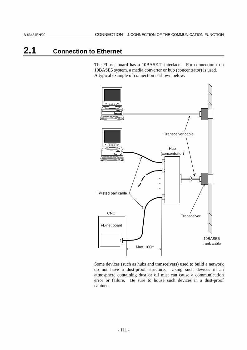
B-63434EN/02 CONNECTION 2.CONNECTION OF THE COMMUNICATION FUNCTION
- 111 -
2.1 Connection to Ethernet
The FL-net board has a 10BASE-T interface. For connection to a10BASE5 system, a media converter or hub (concentrator) is used.A typical example of connection is shown below.
・・・
Max. 100m
FL-net board
CNCTransceiver
10BASE5trunk cable
Transceiver cable
Hub(concentrator)
Twisted pair cable
Some devices (such as hubs and transceivers) used to build a networkdo not have a dust-proof structure. Using such devices in anatmosphere containing dust or oil mist can cause a communicationerror or failure. Be sure to house such devices in a dust-proofcabinet.

2.CONNECTION OF THE COMMUNICATION FUNCTION CONNECTION B-63434EN/02
- 112 -
2.2 Routing of the Ethernet Cable
The Ethernet cable can be routed only from the front of the controlunit. For connector location information, see the outside drawing ofeach board.
Radius of 70 mm or more
Clamp
10BASE-TEthernet cable
Ground plate
The Ethernet cable needs to be secured with a clamp so that notension is applied to the connector (RJ-45) installed at the end of thecable even if the cable is pulled. This clamping also serves as thegrounding of the cable shield.

B-63434EN/02 CONNECTION 2.CONNECTION OF THE COMMUNICATION FUNCTION
- 113 -
2.3 Pin Allocation of the 10BASE-T Connector (CD38N)
CD38NPin No. Signal Meaning
1 TX+ Transmission +2 TX- Transmission -3 RX+ Reception +4 Not used5 Not used6 RX- Reception -7 Not used8 Not used

2.CONNECTION OF THE COMMUNICATION FUNCTION CONNECTION B-63434EN/02
- 114 -
2.4 Twisted Pair Cable Specifications
2.4.1 Cable connection
Referring to the operator’s manual of a device used, select anappropriate cable. An example of straight cable connection betweenthe FL-net board 10BASE-T interface CD38N and a hub (or mediaconverter) is given below.
FL-net boardCD38N
TX+ (1)
TX- (2)
RX+ (3)
RX- (6)
(1) TX+
(2) TX-
(3) RX+
(6) RX-
MAX.100m
RJ-45modular connector
Media converteror hub
Shield
1 TX+2 TX-3 RX+456 RX-78
1 TX+2 TX-3 RX+456 RX-78
- The cable must not be longer than 100 m. Do not extend thecable unnecessarily.

B-63434EN/02 CONNECTION 2.CONNECTION OF THE COMMUNICATION FUNCTION
- 115 -
An example of cross cable connection between the FL-net board10BASE-T interface CD38N and a mediate converter (or hub) isgiven below.
FL-net boardCD38N
TX+ (1)
TX- (2)
RX+ (3)
RX- (6)
(3) TX+
(6) TX-
(1) RX+
(2) RX-
MAX.100m
RJ-45modular connector
Media converteror hub
Shield
1 TX+2 TX-3 RX+456 RX-78
1 TX+2 TX-3 RX+456 RX-78
- The cable must not be longer than 100 m. Do not extend thecable unnecessarily.
NOTEA straight cable is usually used for connectionbetween a communication device and hub. Thecable required for connection may differ dependingon the manufacturer of the hub or media converter,however. Check whether a straight or cross cableis required, then prepare a correct cable.When connection is correct, the LED marked with"LIL" on the FL-net board lights up.

2.CONNECTION OF THE COMMUNICATION FUNCTION CONNECTION B-63434EN/02
- 116 -
2.4.2 Cable wire
As twisted pair cables for 10BASE-T, unshielded cables (UTP cables)are available on the market. For improved protection against noisein an FA environment, however, use a common shielded category-5twisted pair cable (STP cable).
Recommended cables (For standard)Manufacturer name Specification Remarks
The Furukawa Electric Co., Ltd. DTS5087C-4P Twisted wireNissei Electric Co., Ltd. F-4PFWMF Solid wire
Contact pointManufacturer name Contact pointSales Division, theFurukawa ElectricCo., Ltd.
2-6-1 Marunouchi Chiyoda Ward, Tokyo, 100-8233TEL: 03-3286-3126 FAX: 03-3286-3979
Remarks
Tamachi Office,Nissei Electric Co.,Ltd.
MU Building 3F, 1-9-1 Minaminaruse, Machida City,Tokyo 194-0045TEL: 0427-29-2531 FAX: 0427-29-3375
Contact pointfor overseassales
IWATANI International CorporationTokyo Head Office
21-8 NISHI-SHINBASHI 3-CHOME, MINATO-KU,TOKYO, 105-8458, JAPANTEL:03-5405-5810 FAX:03-5405-5666Telex:2524256 IWATYO J
Remarks A processed cable with the both terminal connectoris provided.
NOTEThe recommended standard cables cannot be usedwith movable parts.
Recommended cable (For movable parts)Manufacturer name Specification Remarks
Oki Electric Cable Co.,Ltd.
AWG26 4P TPMC-C5-F(SB) FANUC-specificcable
#1(��-A�&%*%&#�%)�-�:�����-A�&%*%&�(�� � �)�&)���&�)+;
�+#/%�.��=$1�+C� � �55��,,,��, !�
�#�=*#&�=+�+C� � @%��(�&�+%&�#1(��)�����'�
Nagano Sales Office TEL: ,�55�����!4��A�&%*%&#�%)�-
・ �(�&�+%&�&0#+#&��+%-�%&-C� � )�*)+$��)����6����!5��
� &#��.)+%�-���#�'�!�
�)+�+�#-)�-�+�(#��'��)�#����=#�%)��A�+*)+$#�&����0�
'%-�#�&���)��0��0=1�$=-��1��!,�$�)+�-0)+��+�
・ ��+=&�=+�C� � )$$)��-0%�('�(��:1+#%'�'�-0%�(';�� � �+#%�
/%+��A+)?%'�'�

B-63434EN/02 CONNECTION 2.CONNECTION OF THE COMMUNICATION FUNCTION
- 117 -
�0��&)�'=&�)+�%-�����5�#���#(�'�&)AA�+�-�+#�'�'�/%+��
�0��-0�#�0��0%&@��--�%-�,���$$�� � �0��)=�-%'��'%#$���+�%-
5��±,���$$�
・�(#$��+�-%-�#�&�C� � ���!��� � 9���
・ %(�+�-%-�#�&�C� � 3#-�'�)���0�������-�#�'#+'�
:�D=%?#(���� �)� �0�� &)�?���%)�#(� )%(�+�-%-�#��� �(�&�+%&
(�-;
・ �(�2%�.�+�-%-�#�&�C� � ��$%((%)���%$�-�)+�$)+��/%�0�!,�$$�)*
#�1��'�+#'%=-�:��-0#A��*(�2%�.���-�;
・���-�"(���)�C� � �����,��5� � :�,℃6�,�969���;
�)��;� � �(/#"-� =-�� &)���&�)+� ���������:,�;
$#�=*#&�=+�'�1"�7%+)-���(�&�+%&�*)+��0%-�(��
#1(��#--�$1("
� � @%� �(�&�+%&� #1(�� )��� ��'�� #(-)� -=AA(%�-� (�
#--�$1(%�-� =-%�.� &)���&�)+� ���������:,�;
$#�=*#&�=+�'�1"�7%+)-���(�&�+%&�� ��#@��#++#�.�$���-
'%+�&�("� /%�0� �0�� $#�=*#&�=+�+� *)+� �0�� -A�&%*%&#�%)�-
:(��.�0�� )=�.)%�.� %�-A�&�%)��� A#&@%�.�� #�'� )�0�+-;� #�'
A=+&0#-��(��#--�$1(%�-�
)��#&��A)%��C� � @%��(�&�+%&�#1(��)�����'�
�#(�-� &)��#&�� A)%��;� � �#.#�)� �#(�-� **%&�
TEL: ,�55�����!4�

2.CONNECTION OF THE COMMUNICATION FUNCTION CONNECTION B-63434EN/02
- 118 -
2.4.3 Connector Specifications
As a connector used with a twisted pair cable for Ethernet, an 8-bitmodular connector called RJ-45 is used. Use the followingconnector or equivalent:
Specification Manufacturer RemarksFor solid wire 5-569530-3 AMP Japan, Ltd.For solid wire MS8-RSZT-EMC SK KOHKI Co.,
Ltd.Special tool
requiredFor twisted wire 5-569552-3 AMP Japan, Ltd.For twisted wire TM11AP-88P Hirose Electric Co.,
Ltd.Special tool
required
For movable parts Specification Manufacturer RemarksFor cable AWG264P TPMC-C5-F(SB)
���������:,�; Hirose ElectricCo., Ltd.
(Note)
NOTE���������:,�;
)���&�)+�:$#�=*#&�=+�+�-�#�'#+'�A#+�;
�+#/%�.��=$1�+C� � �5���,,,��,���E�
�#�=*#&�=+�+C� � 7%+)-���(�&�+%&�)�����'�
�#�=*#&�=+�+�&#�#().��=$1�+C� � ���������:,�;
)�*)+$-��)����6����!5���&#��.)+%�-���#�'�!�
�)+� 0)/� �)� #--�$1(�� �0�� &)���&�)+� #�'� (��� &)��#&�
7%+)-���(�&�+%&�
:7%+)-�� �(�&�+%&� ��&0�%&#(� ')&=$���� F���������:,�;
)���&�%)�� �+)&�'=+�� �A�&%*%&#�%)�-F� :��&0�%&#(
-A�&%*%&#�%)���).��������5�;�%-�#?#%(#1(��;
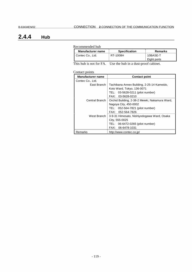
B-63434EN/02 CONNECTION 2.CONNECTION OF THE COMMUNICATION FUNCTION
- 119 -
2.4.4 Hub
Recommended hubManufacturer name Specification Remarks
Contec Co., Ltd. RT-1008H 10BASE-TEight ports
This hub is not for FA. Use the hub in a dust-proof cabinet.
Contact pointsManufacturer name Contact point
Contec Co., Ltd.East Branch Tachibana Annex Building, 2-25-14 Kameido,
Koto Ward, Tokyo, 136-0071TEL: 03-5628-0211 (pilot number)FAX: 03-5628-0210
Central Branch Orchid Building, 2-38-2 Meieki, Nakamura Ward,Nagoya City, 450-0002TEL: 052-564-7821 (pilot number)FAX: 052-564-7826
West Branch 3-9-31 Himesato, Nishiyodogawa Ward, OsakaCity, 555-0025TEL: 06-6472-0265 (pilot number)FAX: 06-6478-1031
Remarks http://www.contec.co.jp/

2.CONNECTION OF THE COMMUNICATION FUNCTION CONNECTION B-63434EN/02
- 120 -
2.5 Noise Protection
2.5.1 Signal line separation
The wiring of Ethernet cables belongs to group C. For the methodof separation from group A wiring and group B wiring, refer to"Connection Manual: Hardware (B-63003EN)" of each CNC.
2.5.2 Cable clamping and shield processing
Clamp those cables that are run into the CNC and require shieldprocessing, as shown below. Process the shield of a twisted paircable for Ethernet in the same way. This clamp processing secures acable, and also processes the shield of the cable. Be sure to performthis clamp processing because it is key to stable operation of thesystem.As shown below, peel off a part of the outer sheath to expose theshield, then press the exposed portion of the shield against the groundplate with a clamp. The machine tool builder is to prepare a groundplate and install it as shown below.
�+)=�'�A(#��
#1(�
#1(��&(#$A
�0%�('
#1(��-0�#�0
�+)=�'�A(#��

B-63434EN/02 CONNECTION 2.CONNECTION OF THE COMMUNICATION FUNCTION
- 121 -
Prepare the following ground plate:
�)=��%�.�-&+�/�0)(�
(#$A�$)=��%�.�0)(�
�+)=�'���+$%�#(
:*)+�.+)=�'%�.;
As a ground plate, use an iron plate as thick as 2 mm or more, andplate it with nickel.
�$$
��$$
�,$$
�+)=�'�A(#��

2.CONNECTION OF THE COMMUNICATION FUNCTION CONNECTION B-63434EN/02
- 122 -
!!�$$�$#2�
��$$
5$$
��$$
Outline Drawing of the Clamp
Ordering code of the clamp: A02B-0124-K001 (8 clamps)

B-63434EN/02 CONNECTION 2.CONNECTION OF THE COMMUNICATION FUNCTION
- 123 -
2.5.3 Network installation
Even when the grounding condition on the machine side is satisfied,noise generated by a machine may induce a communication error onthe communication line, depending on the installation condition andenvironment of the machine. To prevent such trouble, themachine(s) should be separated and insulated from the Ethernet trunkcable and personal computer. Examples of connections are givenbelow.
7�3
��+-)�#(�&)$A=��+
:�)����;
:�)����; :�)����; :�)����;
:�)����;
�,3���!
�+=�@�(�
��4� !�<<10�-�
5����+-)�#(�&)$A=��+6
�+=�@�-%'�
�1�'# .'(1�!�<( (#.���0�"+����B�'����'#.��
�('5.���!0!#���!.��
����(�����(�
�#&0%��
�#&0%�� �#&0%��������
Large network
7�3
������
��+-)�#(�&)$A=��+
:�)����;
��4� !�<<10�-�
5��
��+-)�#(�&)$A=��+6�+=�@�-%'�
�1�'# .'(1�!�<( (#.���0�"+����B�'����'#.��
�('5.���!0!#���!.��
����(�
�#&0%��
:�)����;
Small network
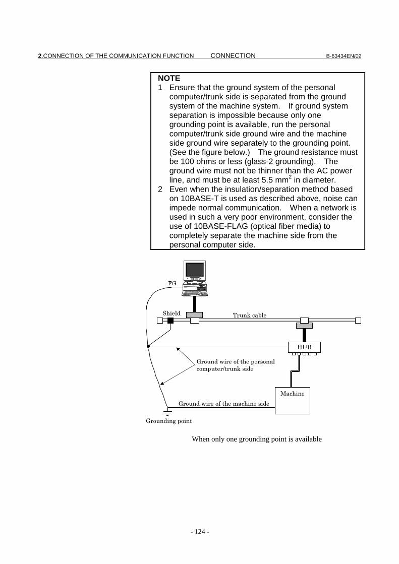
2.CONNECTION OF THE COMMUNICATION FUNCTION CONNECTION B-63434EN/02
- 124 -
NOTE1 Ensure that the ground system of the personal
computer/trunk side is separated from the groundsystem of the machine system. If ground systemseparation is impossible because only onegrounding point is available, run the personalcomputer/trunk side ground wire and the machineside ground wire separately to the grounding point.(See the figure below.) The ground resistance mustbe 100 ohms or less (glass-2 grounding). Theground wire must not be thinner than the AC powerline, and must be at least 5.5 mm2 in diameter.
2 Even when the insulation/separation method basedon 10BASE-T is used as described above, noise canimpede normal communication. When a network isused in such a very poor environment, consider theuse of 10BASE-FLAG (optical fiber media) tocompletely separate the machine side from thepersonal computer side.
7�3
��
�0%�(' �+=�@�(�
�+)=�'�/%+��)*��0��A�+-)�#(
&)$A=��+6�+=�@�-%'�
�+)=�'%�.�A)%��
�#&0%��
�+)=�'�/%+��)*��0��$#&0%���-%'�
When only one grounding point is available

V. MAINTENANCE

B-63434EN/02 MAINTENANCE 1.HARDWARE
- 127 -
1 HARDWARE
This chapter provides hardware information required for themaintenance of the FL-net board.

1.HARDWARE MAINTENANCE B-63434EN/02
- 128 -
1.1 Layout of Components
CD38N
MPU
TM1
CustomLSI
CustomLSI
Name PCB drawing number RemarksFL-net board A20B-8100-0530
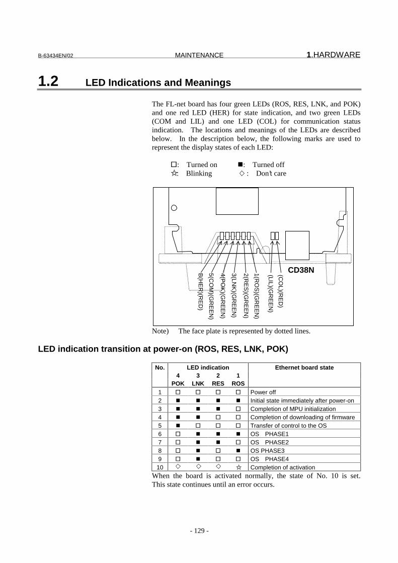
B-63434EN/02 MAINTENANCE 1.HARDWARE
- 129 -
1.2 LED Indications and Meanings
The FL-net board has four green LEDs (ROS, RES, LNK, and POK)and one red LED (HER) for state indication, and two green LEDs(COM and LIL) and one LED (COL) for communication statusindication. The locations and meanings of the LEDs are describedbelow. In the description below, the following marks are used torepresent the display states of each LED:
�: Turned on �: Turned off✩ : Blinking : Don’t care
CD38N4(PO
K)(G
RE
EN
)
3(LNK
)(GR
EE
N)
2(RE
S)(G
RE
EN
)
1(RO
S)(G
RE
EN
)
B(H
ER
)(RE
D)
(LIL)(GR
EE
N)
(CO
L)(RE
D)
5(CO
M)(G
RE
EN
)
Note) The face plate is represented by dotted lines.
LED indication transition at power-on (ROS, RES, LNK, POK)
No. LED indication Ethernet board state4 3 2 1
POK LNK RES ROS1 � � � � Power off2 � � � � Initial state immediately after power-on3 � � � � Completion of MPU initialization4 � � � � Completion of downloading of firmware5 � � � � Transfer of control to the OS6 � � � � OS PHASE17 � � � � OS PHASE28 � � � � OS PHASE39 � � � � OS PHASE4
10 ✩ Completion of activationWhen the board is activated normally, the state of No. 10 is set.This state continues until an error occurs.

1.HARDWARE MAINTENANCE B-63434EN/02
- 130 -
LED indication during normal operationNo. LED indication Communication status
1 ROS ☆ Blinks at 1-second intervals when thecommunication software on the FL-net boardoperates normally.
2 RES □ Normally, off3 LNK ■ Turned on when the node participates in the FL-
net network4 POK ■ Turned on when all FL-net parameters are valid.
LED indication for communication status
No. LED indication Communication status1 COM � Turned on when data is transmitted or received2 LIL � Turned on when the connection with the hub is
normal3 COL � Turned on when a data collision occurs
NOTECOL: The FL-net manages the token-based
transmission right so that no collision occurs. Ifthis LED is turned on frequently, acommunication error has occurred due to noise,or an Ethernet compliant product other than theFL-net is connected.

B-63434EN/02 MAINTENANCE 1.HARDWARE
- 131 -
LED indication when an error occurs (ROS, RES, LNK, POK)
The LEDs repeat the indications of the LONG pattern and SHORTpattern. In this case, the LONG pattern is turned on for a longertime, and the SHORT pattern is turned on for a shorter time.
LED indicationLONG SHORTNo.4 3 2 1 4 3 2 1
Board state
1 ���� ���� Reset exception2 ���� ���� General machine check exception3 ���� ���� Data Storage4 ���� ���� Instruction Storage5 ���� ���� Alignment6 ���� ���� Program7 ���� ���� Floating Point Unavailable8 ���� ���� Decrementer9 ���� ���� Trace
10 ���� ���� Floating Point Assist11 ���� ���� Implementation Dependent Software Emulation12 ���� ���� Implementation Dependent Instruction TLB Miss13 ���� ���� Implementation Dependent Data TLB Miss14 ���� ���� Implementation Dependent Instruction TLB Error15 ���� ���� Implementation Dependent Data TLB Error16 ���� ���� Implementation Dependent Data Breakpoint17 ���� ���� Implementation Dependent Instruction Breakpoint18 ���� ���� Implementation Dependent Peripheral Breakpoint19 ���� ���� Implementation Dependent Non Maskable Development20 ���� ���� DRAM Parity Alarm21 ���� ���� Other NMI22 ���� ���� Invalid interrupt
Note) If any of these errors occurs, contact FANUC.
LED indication when an error occurs (HER)
No. LED indication Board state1 HER � A parity error occurred in the main memory.

1.HARDWARE MAINTENANCE B-63434EN/02
- 132 -
1.3 Setting Pin
The FL-net board has a setting pin (TM1) installed. The B side isconnected with a jumper plug (factory setting). If the plug isremoved, or the setting is changed, the FL-net board does not operatenormally.
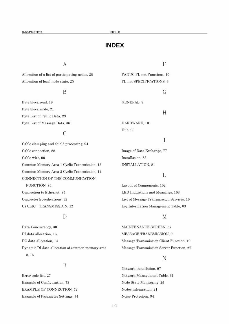
B-63434EN/02 INDEX
%��
INDEX
�
�(()&#�%)��)*�#�(%-��)*�A#+�%&%A#�%�.��)'�-����
�(()&#�%)��)*�()&#(��)'��-�#�����!
�
3"���1()&@�+�#'���4
3"���1()&@�/+%������
3"����%-��)*�"&(%&��#�#���4
3"����%-��)*���--#.���#�#���5
�
#1(��&(#$A%�.�#�'�-0%�('�A+)&�--%�.��4
#1(��&)���&�%)�����
#1(��/%+���4,
)$$)����$)+"��+�#���"&(%&��+#�-$%--%)�����
)$$)����$)+"��+�#���"&(%&��+#�-$%--%)����
����� �� ���7�� �������� �
����� ����
)���&�%)���)���0�+������!
)���&�)+��A�&%*%&#�%)�-��4�
���� � ��������� �����
�
�#�#�)�&=++��&"���,
���'#�#�#(()&#�%)����5
� �'#�#�#(()&#�%)����
�"�#$%&����'#�#�#(()&#�%)��)*�&)$$)��$�$)+"�#+�#
����5
�
�++)+�&)'��(%-�����
�2#$A(��)*�)�*%.=+#�%)�����
�8������ �� ����� �����
�2#$A(��)*��#+#$���+�����%�.-���
�
�������������=�&�%)�-���,
���������������� ����5
�
���������
�
7��������,�
7=1��4�
�$#.��)*��#�#��2&0#�.�����
��-�#((#�%)�����
���������� �����
�#")=��)*�)$A)����-���,�
������'%&#�%)�-�#�'���#�%�.-���,�
�%-��)*���--#.���+#�-$%--%)����+?%&�-���,
�).���*)+$#�%)���#�#.�$�����#1(���5�
�
�����������������!�
����������������� ���4
��--#.���+#�-$%--%)��(%�����=�&�%)����4
��--#.���+#�-$%--%)����+?�+��=�&�%)�����
�
���/)+@�%�-�#((#�%)���4�
���/)+@��#�#.�$�����#1(���5�
�)'����#����)�%�)+%�.���!
�)'�-�%�*)+$#�%)�����
�)%-���+)��&�%)���4

INDEX B-63434EN/02
%��
�)��-�)���(()&#�%)��%���0������+�#����
?�+?%�/�� ,
�
������������������4
�#+�%&%A#�%�.��)'���#�#.�$�����#1(���!�
�%���(()&#�%)��)*��0���,3������)���&�)+�:����;�
��
�)/�+��#���i�� �����67��!�
�)/�+��#���i�� �����67��55
�+)&�'=+��*)+���--#.���+#�-$%--%)�� A�+#�%)�����
�+)&�'=+��*)+�)A�+#�%�.��0��$�--#.���+#�-$%--%)�
&(%����*=�&�%)�����
�+)&�'=+��*)+�)A�+#�%�.��0���+#�-A#+����$�--#.�
�+#�-$%--%)��*=�&�%)�����
�+)&�'=+��)*��0����--#.���+#�-$%--%)���=�&�%)�����
�
�&�A�%)��)*�#�$�--#.��/%�0�&)�*%+$#�%)�����
�-A)�-��$�--#.���+#�-$%--%)����
)=�%�.�)*��0����0�+����#1(����5
�
��+%�-��5i6��i6��i���� �
��+?�+��=�&�%)��)*��+#�-$%��%�.�#���--#.��/%�0
)�*%+$#�%)�����
����%�.�)*��#+#$���+-�� �
����%�.��%����,5
�%.�#(�(%���-�A#+#�%)���4
�A�&%*%&#�%)�-����
��#�%&����'#�#�#(()&#�%)��)*�&)$$)��$�$)+"�#+�#���
�4
�
�%$%�.�)*�-/%�&0%�.�1��/����&)�'%�%)�-�)��'#�#
�2&0#�.��/%�0�&)$$)��$�$)+"�#+�#������
�+#�-A#+����$�--#.��+�&�A�%)�����
�+#�-A#+����$�--#.���+#�-$%--%)����4
�+#�-A#+������--#.���+#�-$%--%)���=�&�%)����4
�/%-��'��#%+�#1(���A�&%*%&#�%)�-����
�
9%+�=#(�#''+�--�-A#&��#(()&#�%)��������!
�
�0#���-��0������������
�)+'�1()&@�+�#'����
�)+'�1()&@�/+%�����!

EUROPEAN HEADQUARTERS –GRAND-DUCHÉ DE LUXEMBOURG
GE Fanuc Automation Europe S.A.Zone IndustrielleL-6468 Echternach (+352) 727979 - 1
(+352) 727979 – 214
www.gefanuceur.com
BELGIUM / NETHERLANDSGE Fanuc Automation Europe S.A.
- Netherlands Branch -Postbus 7230 - NL-4800 GE BredaMinervum 1603A - NL-4817 ZL Breda
(+31) 76-5783 201 (CNC) (+31) 76-5783 212 (PLC)
(+31) 76-5870 181
www.gefanuc.nl
CZECH REPUBLICGE Fanuc Automation CR s.r.o.
U studanky 3CZ-170 00 Praha 7
(+420) 2 333 72 502 (CNC) (+420) 2 333 72 503 (PLC)
(+420) 2 333 70 821
www.gefanuc.cz
FRANCEGE Fanuc Automation France S.A.39, rue du Saule Trapu, BP 219
F-91882 Massy Cedex (+33) 1 69 75 86 39 (CNC) (+33) 1 69 75 86 20 (PLC)
(+33) 1 69 75 86 49
www.gefanuc.fr
GERMANYGE Fanuc Automation GmbHBernhäuser Straße 22
D-73765 Neuhausen a.d.F (+49) 7158 187 400
(+49) 7158 187 455 (CNC) (+49) 7158 187 466 (PLC)
www.gefanuc.de
GERMANYGE Fanuc Eberle Automation GmbH
Ernst-Weyden-Str. 7D-51105 Köln (Cologne)
(+49) 221-83904-53 (+49) 221-83904-55
www.gefanuc.de
GERMANYGE Fanuc Automation GmbH
Elberfelderstr. 45D-40724 Hilden
(+49) 2103 247410 (Laser/CNC) (+49) 2103 247420 (Laser/CNC)
www.gefanuc.de
GERMANYGE Fanuc Automation GmbH
Obere Hauptstr. 72D-09244 Lichtenau
(+49) 37208 695 20(CNC) (+49) 37208 695 30 (PLC)
(+49) 37208 695 55
www.gefanuc.de
GERMANYGE Fanuc Automation Deutschland GmbH
Bensheimer Str. 61D-65428 Rüsselsheim (+49) 6142 357600 (+49) 6142 357611
www.gefanuc.de
GERMANYGE Fanuc Eberle Automation GmbH
Südwestpark 48D-90449 Nürnberg
(+49) 911 9672 100 (PLC) (+49) 911 9672 200 (PLC)
www.gefanuc.de
GERMANYGE Fanuc Eberle Automation GmbH
Reichenbergerstr. 6D-33605 Bielefeld
(+49) 521 92445 0 (PLC) (+49) 521 92445 30 (PLC)
www.gefanuc.de
SWEDENGE Fanuc Automation Nordic AB
Hammarbacken 4S-19149 Sollentuna (+46) 8 444 5520 (+46) 8 444 5521
www.gefanuc.se
ITALYGE Fanuc Automation Italia S.r.l.
Piazza Tirana 24/4BI-20147 Milano
(+39) 02 413 81 41 (CNC) (+39) 02 419 669 (CNC)
www.gefanuc.it
ITALYGE Power Controls Italia S.p.a
Via Tortona 27I-20144 Milano
(+39) 02 4242 280 (PLC) (+39) 02 4242 511 (PLC)
www.gefanuc.it
SPAINGE Fanuc Automation España S.A.
Polígono Industrial OlasoCalle Olaso, 57 - Locales 10 y 11
E-20870 Elgoibar (+34) 943 74 82 90 (CNC) (+34) 943 74 44 21 (CNC)
www.gefanuc.es
SPAINGE Power Controls Ibérica S.L.Calle Marqués de Comillas, 1E-08225 Terrassa (Barcelona)
(+34) 93 736 58 28 (PLC) (+34) 93 788 24 03 (PLC)
www.gefanuc.es
SWITZERLANDGE Fanuc Automation
Filiale Suisse/Niederlassung SchweizErlenstrasse 35a
CH-2555 Brügg b. Biel (+41) 32 366 63 63 (CNC) (+41) 32 366 63 33 (PLC) (+41) 32 366 63 64 (CNC) (+41) 32 366 63 34 (PLC)
www.gefanuc.ch
UNITED KINGDOMGE Fanuc Automation (UK) Ltd.
Unit 1 - Mill SquareFeatherstone Road
Wolverton Mill SouthMilton Keynes MK12 5BZ
(+44) 1908 84 4000 (+44) 1908 84 4001
www.gefanuceur.co.uk
02/01

Printed at GE Fanuc Automation S.A. , LuxembourgPrinted at GE Fanuc Automation S.A. , LuxembourgPrinted at GE Fanuc Automation S.A. , LuxembourgPrinted at GE Fanuc Automation S.A. , Luxembourg