b-2014-106-sc-3000 process feed study scope of work
DESCRIPTION
Process FEED Study Scope of Work Lake Kivu AntaresTRANSCRIPT

Lake Kivu Gas Extraction Project
PROCESS FEED STUDY SCOPE
Project No: B-2014-106 Document No: B-2014-106-SC-3000
B 11/14/2014 Issued for Review ARE KM JJ Client
A 11/12/2014 Issued for Internal Review ARE KM JJ Client
Rev. Date Description Originator Checked Approved
Revision Status
Approval

Document number: Client: Page:
B-2014-106-SC-3000 SYMBION POWER LLC 2 of 22
Revision No:
PROCESS FEED STUDY SCOPE Date:
B 11/14/2014
RECORD OF AMENDMENT
REVISION NO.
AMENDED SECTION
PARA. NO.
DESCRIPTION OF CHANGES
Document number: Client: Page:
B-2014-106-SC-3000 SYMBION POWER LLC 3 of 22
Revision No:
PROCESS FEED STUDY SCOPE Date:
B 11/14/2014
TABLE OF CONTENTS
PROCESS FEED STUDY SCOPE................................................................................ 1
1. Introduction .......................................................................................................... 4
2. Background .......................................................................................................... 4
3. Terms and Definitions ......................................................................................... 5
4. Facilities Description ........................................................................................... 7
5. Process FEED Study Scope of Work ................................................................ 10
6. Design Conditions ............................................................................................. 13
6.1 Local Conditions ................................................................................... 13 6.2 Feed Water Composition ...................................................................... 13 6.3 Export Pipeline ..................................................................................... 14 6.4 Fuel Gas Specifications ........................................................................ 14
7. Process Simulation ............................................................................................ 15
7.1 Gas Extraction and Treating Process ................................................... 16 7.1.1 Offshore Gas Extraction Facilities:........................................................ 16 7.1.2 Onshore Gas Treating Facilities: .......................................................... 16
8. PROCESS FLOW DIAGRAM (PFD) ................................................................... 18
9. OFFSHORE GAS EXTRACTION FACILITY SCHEMATICS............................... 20
Document number: Client: Page:
B-2014-106-SC-3000 SYMBION POWER LLC 4 of 22
Revision No:
PROCESS FEED STUDY SCOPE Date:
B 11/14/2014
1. Introduction
Antares Offshore has been awarded by Symbion Power LLC with the Engineering Project Management of a Methane Gas Extraction and Treating Plant in Lake Kivu, Rwanda; the methane gas produced will be used to power reciprocating gas engine generator sets producing electricity in 7MW increments up to 56MW. Current phase of the project consists of a FEED Study of the process for Offshore Gas Extraction Facilities and Onshore Gas Treatment Facilities. This document sets the Scope of Work for FEED Process Engineering.
2. Background
Lake Kivu is located on the border between the Republic of Rwanda and the Democratic Republic of Congo. The Lake is 485 meters depth with a surface area of 2400 km2 at an altitude of 1462 m. Lake Kivu contains 300 Km3 of dissolved carbon dioxide and 55 to 60 Km3 of methane gas accumulated and trapped at significant depth in the lake. The discovery of methane in the deep waters of the lake was made in 1935 while trying to understand why there were no fish in the lake. A number of studies of the lake and its potential resource have been done since the discovery. The most comprehensive is the work by Dr. Klaus Tietze in 1976. This work, along with other studies, forms the basis of the technical information being used by Symbion and Antares Offshore for the design of the gas extraction facilities. This project will use Lake Kivu’s methane resources for a commercial benefit for the people of Rwanda, but it will also reduce the risk of an environmental disaster. The scientific community, through the various studies, has predicted that without the production of methane and carbon dioxide, there is a significant risk of a sudden release of large quantities of these gases within the next 100-200 years. Such a release has the potential to kill many thousands of people living around the lake from asphyxiation. Rather than just vent the ± 2 trillion cubic feet (56.6 km3) of methane, this project will use the produced methane for power generation. The technology proposed by Symbion and Antares is similar in principle to that utilized by the KivuWatt facility but with noteworthy improvements and risk reducing measures. The extraction method is based upon a well-established technology in the oil and gas industry known as “gas lift”. Gas lift was used on Lake Kivu from the mid-1960s through 2004 to extract CH4 for use in the boilers at the Bralirwa Brewery on the northern Rwanda shores of Lake Kivu. Gas lift is also the principle behind the degassing of Lakes Nyos and

Document number: Client: Page:
B-2014-106-SC-3000 SYMBION POWER LLC 5 of 22
Revision No:
PROCESS FEED STUDY SCOPE Date:
B 11/14/2014
Monoun in Cameroon where CO2 of volcanic origin within these deep lakes causes
periodic eruptions. Additionally, KP1 pilot plant (Kibuye Stage 1 Power Limited) is currently producing 4MW of power and plans to increase production up to 10MW. In addition, KivuWatt by ContourGlobal is in the final stage of construction of a 26 MW facility.
Figure 1.0
Lake Kivu Map (from Google Earth)
3. Terms and Definitions
This section describes the terms and definitions employed in this document, including acronyms used in other sections of this document.
Term Definition
COMPANY Symbion Power LLC.
ANTARES OFFSHORE Contractor nominated by COMPANY to design the Gas Extraction Facilities.
VENDOR Responsible party selected by COMPANY and ANTARES OFFSHORE for develop FEED study in this specification.
FRSS Freestanding Riser and Separator System
MCC Motor Control Center

Document number: Client: Page:
B-2014-106-SC-3000 SYMBION POWER LLC 6 of 22
Revision No:
PROCESS FEED STUDY SCOPE Date:
B 11/14/2014
P&ID Piping and Instrumentation Diagrams
PFD Process Flow Diagrams
SCADA Supervisory Control And Data Acquisition
UPS Uninterruptible Power Supply
NRTL Non-Random Two-Liquid model
EOS Equation of State
BIP Binary Interaction Parameters
Document number: Client: Page:
B-2014-106-SC-3000 SYMBION POWER LLC 7 of 22
Revision No:
PROCESS FEED STUDY SCOPE Date:
B 11/14/2014
4. Facilities Description
Symbion’s gas extraction facilities will be design by Antares to lift, separate and process gas which is dissolved in the deep waters of Lake Kivu and deliver it to an onshore generating facility located at Cape of Busororo in Nyamyumba area. The proposed freestanding riser and separator system (FRSS) is based on the design principles and extensive engineering carried by Antares work on KivuWatt and Antares’ subsequent improvement of the system. The key element of the gas extraction facility is the gas separation process below the water level. The water is pulled from the lake through the inlet riser and then the dissolved gas is freed from the water in the separator. The wet gas is then sent from the separator to the process facility while the degassed water will be put back into the lake through the outlet riser. The pressure in the separator is the key to obtaining the optimum methane content for the gas engines. The proposed system is different to that employed by Kivuwatt in that the unique FRSS is decoupled from the barge. One FRSS module is capable of producing 1.5mmscfd of 85% methane; sufficient for a 7MW power plant. The 48” diameter inlet riser has been determined to be the ideal size for the volume of water lifted versus gas produced. This inlet riser will lift water from approximately 355 water depth and the 42” diameter outlet riser will discharge the degassed water at around 280m water depth in accordance with Lake Kivu’s Management Prescriptions. The FRSS will be deployed to a depth of 20m and the produced gas will be piped via a flexible pipeline/riser to the barge. Segregation of the riser separator away from the process facility provides better safety features, additionally providing greater spread in the area from which gas may be extracted. The method is a modular concept and Symbion proposes an incremental expansion of power output by building additional modules as outlined below.
1. Phase 1: The initial stage will consist of a single FRSS, offshore gas export facility and onshore process plant to generate 7 MW (see Figure 2). The offshore gas export facility will be minimal and limited to gas drying equipment (scrubbers), compressor, control room and export pipeline tethered at -20m. The raw gas will be washed and processed to achieve fuel gas quality gas. The main process items are the washing tower, the wash water inlet, the discharge over boarding lines, and other supporting equipment. The plant will be provided with flaring capability.
2. Phase 2: An additional FRSS will be added to the existing 7MW facility to increase
the gas production (see Figure 3). To onshore facility will be expanded to accommodate an additional wash tower and other equipment. With this additional FRSS, gas output will double and the plant will generate 14MW of power.

Document number: Client: Page:
B-2014-106-SC-3000 SYMBION POWER LLC 8 of 22
Revision No:
PROCESS FEED STUDY SCOPE Date:
B 11/14/2014
Figure 2. 7MW Gas Extraction Facility (Phase 1).
Figure 3. 14MW Gas Extraction Facility (Phase 2).

Document number: Client: Page:
B-2014-106-SC-3000 SYMBION POWER LLC 9 of 22
Revision No:
PROCESS FEED STUDY SCOPE Date:
B 11/14/2014
3. Phases 3 and 4: The system proposed to the end of Phase 2 will be doubled in
Phase 3 to take the power output to 28MW and then doubled again to take output to 56MW as part of Phase 4.
Figure 4. 28MW Gas Extraction Facility (Phase 3).
Symbion’s phased modular approach has the advantage of not building a single large barge with concentrated risk and facilities gathering gas from a larger area rather than a single concentrated area. In addition, FRSS can be relocated around the lake for re-use in different areas with minimal difficulty. The FRSS design will also enable the cost and schedule of future gas extraction facility developments to be significantly reduced. The offshore facilities will include barges containing minimal gas processing equipment, a pipeline from the barge to shore while the onshore gas processing facility will contain the bulk of the equipment for scrubbing/flaring, as well as an onshore section of the pipeline containing metering facilities with the boundary of the power plant.

Document number: Client: Page:
B-2014-106-SC-3000 SYMBION POWER LLC 10 of 22
Revision No:
PROCESS FEED STUDY SCOPE Date:
B 11/14/2014
Figure 5. 56MW Gas Extraction Facility (Phase 4).
5. Process FEED Study Scope of Work
Document number: Client: Page:
B-2014-106-SC-3000 SYMBION POWER LLC 11 of 22
Revision No:
PROCESS FEED STUDY SCOPE Date:
B 11/14/2014
This document describes the key functional and technical parameters to be used in the process design for the offshore gas extraction facility, and the onshore gas treating facility. As part of the process design, process simulations must to be perform in order to validate the viability of the process, process simulations must to be run by using industry recognized software, including OLGA, HYSYS and/or ASPEN PLUS or similar in order to confirm flow rates, two phase flows, flow compositions and establish design parameters to be used for equipment and piping systems design.
The onshore treatment facilities must to be design to produce fuel gas in compliance with the gas engines fuel requirements (Table 3). Based on process simulation data, Vendor must to size and develop specifications and data sheets for both offshore and onshore process equipment, including, but not limited to: 1. Underwater Gas Separator. 2. Auto-siphon pumping system. 3. Raw Gas Compression Skid, including suction and discharge scrubbers, and cooling system. 4. Close Drain System. 5. Flare System. 6. Refrigeration Package. 7. Cooling Media Skid. 8. Export Pig Launcher. 9. Onshore Slug Catcher (if required) 10. Onshore Raw/Sweet Gas Compression Skid, including suction and discharge scrubbers, and cooling system. 11. Wash Water Towers. Internals specification must to be included. 12. Wash Water Riser and Pumping and Filtering System. 13. Fuel Gas Dehydrator System. 14. Fuel Gas Metering System. 15. Interfaces with Gas engines 16. Close drain and sewage treatment unit. 17. Flare System including supplemental fuel system. Is Vendor scope:
1. To review and consolidate Process Flow Diagrams (PFDs). 2. To develop Process Heat and Material Balance Sheets. 3. To develop preliminary Utility Flow Diagrams. 4. To develop Piping and Instrumentation Diagrams (P&IDs). 5. Equipment, Line and Control and Relief Valves Sizing Calculations.

Document number: Client: Page:
B-2014-106-SC-3000 SYMBION POWER LLC 12 of 22
Revision No:
PROCESS FEED STUDY SCOPE Date:
B 11/14/2014
6. Equipment layout for Offshore Gas Extraction Facility. 7. Equipment layout for Onshore Treatment Facility.
Upon approval of P&ID and equipment layouts, is in Vendor Scope to develop the corresponding:
1. Piping size studies. 2. Process and utilities pipe specifications and datasheets. 3. Preliminary Piping Materials Take-Off.
Vendor Scope of work includes the specifications and data sheets for control, electrical and safety systems for both offshore and onshore facilities. Vendor must to develop specification and datasheets for:
1. SCADA system 2. Control and Monitoring equipment. 3. Determine parasitic power requirements and supply system for onshore and
offshore facilities, including data sheet and specification for black start generator.
4. Motor Control Center (MCC). 5. Battery System and UPS. 6. Transformers. 7. Firewall Design and Details (if required).
As part of the above systems, Vendor must to develop:
1. Preliminary Electrical Diagrams. 2. Preliminary Control System Diagrams. 3. SAFE Charts and Safety Flow Diagrams. 4. Hazardous Area Classification Plans. 5. MCC schematics 6. Cable Schedules. 7. Electrical Studies/Reports and Calculations. 8. Electrical Loads Lists. 9. Instrumentation Specifications/Datasheets. 10. Safety Equipment List 11. Gas Measurement Skid specification and date sheet 12. Instrument datasheets for off-skid instruments. 13. I/O Lists 14. Fire and Gas Detection System Design Philosophy. 15. Fire and Gas Detection System Specification. 16. Control and Shutdown System Philosophy. 17. Instrument Index.
Document number: Client: Page:
B-2014-106-SC-3000 SYMBION POWER LLC 13 of 22
Revision No:
PROCESS FEED STUDY SCOPE Date:
B 11/14/2014
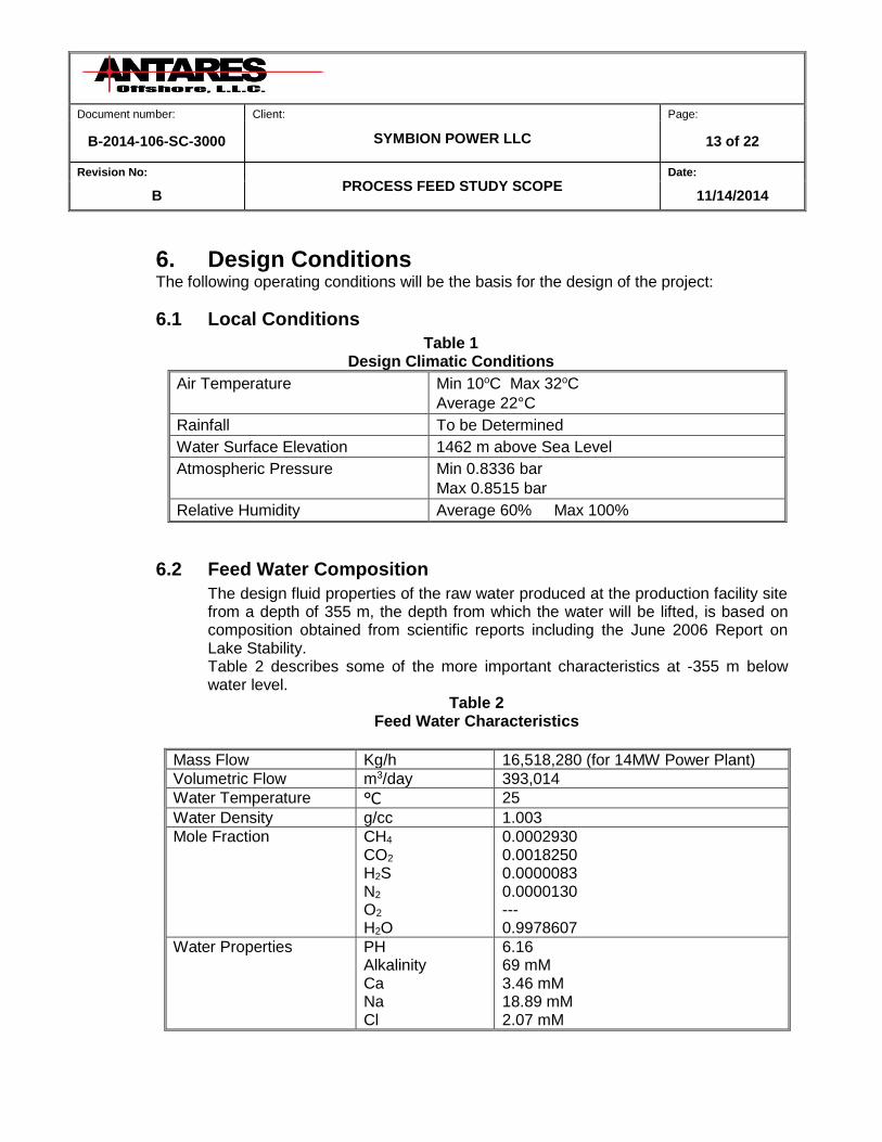
6. Design Conditions The following operating conditions will be the basis for the design of the project:
6.1 Local Conditions
Table 1 Design Climatic Conditions
Air Temperature Min 10oC Max 32oC
Average 22°C
Rainfall To be Determined
Water Surface Elevation 1462 m above Sea Level
Atmospheric Pressure Min 0.8336 bar
Max 0.8515 bar
Relative Humidity Average 60% Max 100%
6.2 Feed Water Composition
The design fluid properties of the raw water produced at the production facility site from a depth of 355 m, the depth from which the water will be lifted, is based on composition obtained from scientific reports including the June 2006 Report on Lake Stability. Table 2 describes some of the more important characteristics at -355 m below water level.
Table 2 Feed Water Characteristics
Mass Flow Kg/h 16,518,280 (for 14MW Power Plant)
Volumetric Flow m3/day 393,014
Water Temperature °C 25
Water Density g/cc 1.003
Mole Fraction CH4 CO2 H2S N2 O2 H2O
0.0002930 0.0018250 0.0000083 0.0000130 --- 0.9978607
Water Properties PH Alkalinity Ca Na Cl
6.16 69 mM 3.46 mM 18.89 mM 2.07 mM
Document number: Client: Page:
B-2014-106-SC-3000 SYMBION POWER LLC 14 of 22
Revision No:
PROCESS FEED STUDY SCOPE Date:
B 11/14/2014
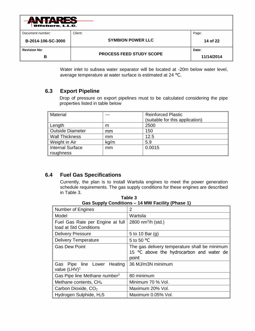
Water inlet to subsea water separator will be located at -20m below water level,
average temperature at water surface is estimated at 24 °C.
6.3 Export Pipeline
Drop of pressure on export pipelines must to be calculated considering the pipe properties listed in table below
Material --- Reinforced Plastic (suitable for this application)
Length m 2500
Outside Diameter mm 150
Wall Thickness mm 12.5
Weight in Air kg/m 5.9
Internal Surface roughness
mm 0.0015
6.4 Fuel Gas Specifications
Currently, the plan is to install Wartsila engines to meet the power generation schedule requirements. The gas supply conditions for these engines are described in Table 3.
Table 3 Gas Supply Conditions – 14 MW Facility (Phase 1)
Number of Engines 2
Model Wartsila
Fuel Gas Rate per Engine at full load at Std Conditions
2800 nm3/h (std.)
Delivery Pressure 5 to 10 Bar (g)
Delivery Temperature 5 to 50 °C
Gas Dew Point The gas delivery temperature shall be minimum
15 °C above the hydrocarbon and water de
point
Gas Pipe line Lower Heating value (LHV)1
36 MJ/m3N minimum
Gas Pipe line Methane number2 80 minimum
Methane contents, CH4 Minimum 70 % Vol.
Carbon Dioxide, CO2 Maximum 20% Vol.
Hydrogen Sulphide, H2S Maximum 0.05% Vol.

Document number: Client: Page:
B-2014-106-SC-3000 SYMBION POWER LLC 15 of 22
Revision No:
PROCESS FEED STUDY SCOPE Date:
B 11/14/2014
Total sulphur Maximum 5 mg/Kg
Hydrogen, H2 Maximum 3% Vol.
Water and Hydrocarbon condensates before the engine
Not Allowed
Ammonia Maximum 25 mg/m3N
Chlorine + Fluorine’s Maximum 50 mg/m3N
Particles or solids, content Maximum 50 mg/m3N
Particles or solids sizes Maximum 5µm 1Values given in m3
N are at 0 °C and 101.3 kPa. 2Methane number (MN) determined by the program AVL 3.2 with engine specific corrections, Minimum value dependent on receiver temperature. This is not CH4 content, Wartsila to calculate MN once final gas composition given.
7. Process Simulation
The gas extraction and removal process in the gas extraction facility is highly unique and is one that has not been studied in depth previously on a process simulation level. Earlier attempts at modeling the process have been misleading because ill-suited fluid packages have been employed.
The majority of the fluid system consists of polar components (see table 2), we can see that CH4 is the only hydrocarbon component and that the vast majority of the fluid consists of polar components. Consequently, we see the need to find a fluid package that accounts for an abundance of polar, non-ideal character. Activity models are dual-approach correlations which use empirical data to predict interactions in the liquid-phase non-ideal regions and apply a conventional EOS to the ideal portions of the solution. Some activity models include NRTL, Wilson, and UNIQUAC. Due to the large relative amounts of polar, non-ideal components (H2O and CO2), a proper Activity model must to be applied to the process simulation of gas extraction and treating facilities. Activity models work by invoking binary interaction parameters (BIPs). These BIPs are used by the activity model to calculate how one component will interact with another in the fluid mixture. Fluid Package to be used must to contain a well suited library of BIPs for gas extraction process and must to be suited to handle no-ideal fluid systems.

Document number: Client: Page:
B-2014-106-SC-3000 SYMBION POWER LLC 16 of 22
Revision No:
PROCESS FEED STUDY SCOPE Date:
B 11/14/2014
7.1 Gas Extraction and Treating Process
Attachments in section 5 include the proposed Process Flow Diagram for the Offshore Gas Extraction and Onshore Gas Treating Facilities.
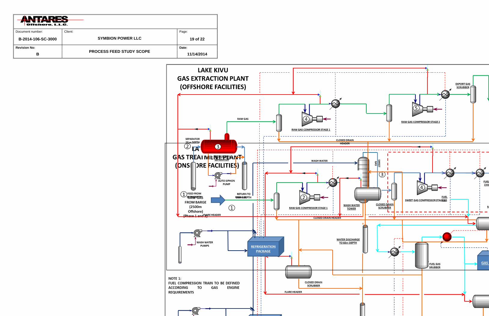
7.1.1 Offshore Gas Extraction Facilities:
1. The water inlet will be located at 355m below water level, water composition and properties as per Table 2. Feed water will be lifted to gas separator by an auto siphon process and gas lifting effects.
2. The gas separators will be located at 20m below water level; gas separator will operate at ambient temperature and hydrostatic pressure. Degassed water will be returned to the Lake at 280m below water level. Two separators operating in parallel are considered to produce the fuel gas required for a 14MW power plant. An efficiency of 75% is recommended for gas separators.
3. Raw gas produced in gas separator will be feed to a compression train located on a barge in the Lake.
4. A multistage compression train integrated by two compressor skids
working in parallel will raise the raw gas pressure in order to be delivered to the onshore gas treatment facilities.
5. The capacities of compressors, cooling requirements and water discharge
flows must to be establishing in order to provide enough information for the sizing and design of compression system.
6. Compression train must provide the raw gas with enough pressure to
account for the drop of pressure on the export gas pipeline, see section 3.3 for export gas pipeline characteristics.
7.1.2 Onshore Gas Treating Facilities:
1. Raw gas from offshore facilities will be recompressed in order to be feed into the wash water towers.
2. Raw gas pressure must to be establish in order optimize the CH4 recovering process.
Document number: Client: Page:
B-2014-106-SC-3000 SYMBION POWER LLC 17 of 22
Revision No:
PROCESS FEED STUDY SCOPE Date:
B 11/14/2014
3. No solvents or additives are considered to be added to wash water to be
feed into the wash water towers, wash water will be fresh water from Lake Kivu at ambient temperature. A sensitivity study must to be done in order to establish the optimal operation parameters and sizes of wash water towers (two wash water towers are considered to treat the gas required by a 14MW power plan).
4. A compression train will be required to deliver the fuel gas to the power generation facilities; gas engines are considered to be contiguous to gas treatment plant.
5. Gas treatment facilities must to deliver fuel gas according to the fuel gas requirements established in Table 3.
6. Process simulation must to provide enough data in order to perform detailed design of systems and equipment for Gas Extraction Facility and Gas Treatment Facility.
Document number: Client: Page:
B-2014-106-SC-3000 SYMBION POWER LLC 18 of 22
Revision No:
PROCESS FEED STUDY SCOPE Date:
B 11/14/2014
8. PROCESS FLOW DIAGRAM (PFD)
Document number: Client: Page:
B-2014-106-SC-3000 SYMBION POWER LLC 19 of 22
Revision No:
PROCESS FEED STUDY SCOPE Date:
B 11/14/2014

Document number: Client: Page:
B-2014-106-SC-3000 SYMBION POWER LLC 20 of 22
Revision No:
PROCESS FEED STUDY SCOPE Date:
B 11/14/2014
9. OFFSHORE GAS EXTRACTION FACILITY SCHEMATICS

Document number: Client: Page:
B-2014-106-SC-3000 SYMBION POWER LLC 21 of 22
Revision No:
PROCESS FEED STUDY SCOPE Date:
B 11/14/2014

Document number: Client: Page:
B-2014-106-SC-3000 SYMBION POWER LLC 22 of 22
Revision No:
PROCESS FEED STUDY SCOPE Date:
B 11/14/2014