b-1 adm740, appendix b, june 2007 copyright 2007 msc.software corporation appendix b four-post...
TRANSCRIPT

B-1ADM740, Appendix B, June 2007Copyright 2007 MSC.Software Corporation
APPENDIX B
FOUR-POST VERTICAL EXCITATION TEST

B-2ADM740, Appendix B, June 2007Copyright 2007 MSC.Software Corporation
B-3ADM740, Appendix B, June 2007Copyright 2007 MSC.Software Corporation
Four-Post Vertical Excitation Test
● This tutorial teaches you how to work with custom Adams/Car test rigs, custom simulation procedures, and how to create a private Adams/Car binary.
● You will work with an existing test rig created in Adams/Car Template Builder. This tutorial will overview the internal workings of the test rig, cover the steps used in making it, and then detail how to edit it and create a custom Adams/Car binary containing the test rig.
● Go through the following KB Article about using Fourpost testrig that comes with the Standard Adams Installation.
Using Four Post testrig in A/CarSolution#: 1-52860800
http://support.mscsoftware.com/kb/results_kb.cfm?S_ID=1-52860800
B-4ADM740, Appendix B, June 2007Copyright 2007 MSC.Software Corporation
Four-Post Vertical Excitation Test
● To go through this tutorial, you must have access to the seven four-post test rig model, macro, and interface files: acar_build.cmd, acme_3PostRig.cmd, acme_four_sim.cmd, macros_ana.cmd, mac_ana_ful_fou_sub.cmd, acme_4PostRig.cmd., and fourpost_header.txt. Ask your instructor for these files.
B-5ADM740, Appendix B, June 2007Copyright 2007 MSC.Software Corporation
Four-Post Vertical Excitation Test
● What’s in this appendix:● Introduction● Creating a test rig template in Adams/Car● Preparing to create a private binary● On UNIX:● Adding custom analysis procedures to Adams/Car
B-6ADM740, Appendix B, June 2007Copyright 2007 MSC.Software Corporation
Four-Post Vertical Excitation Test
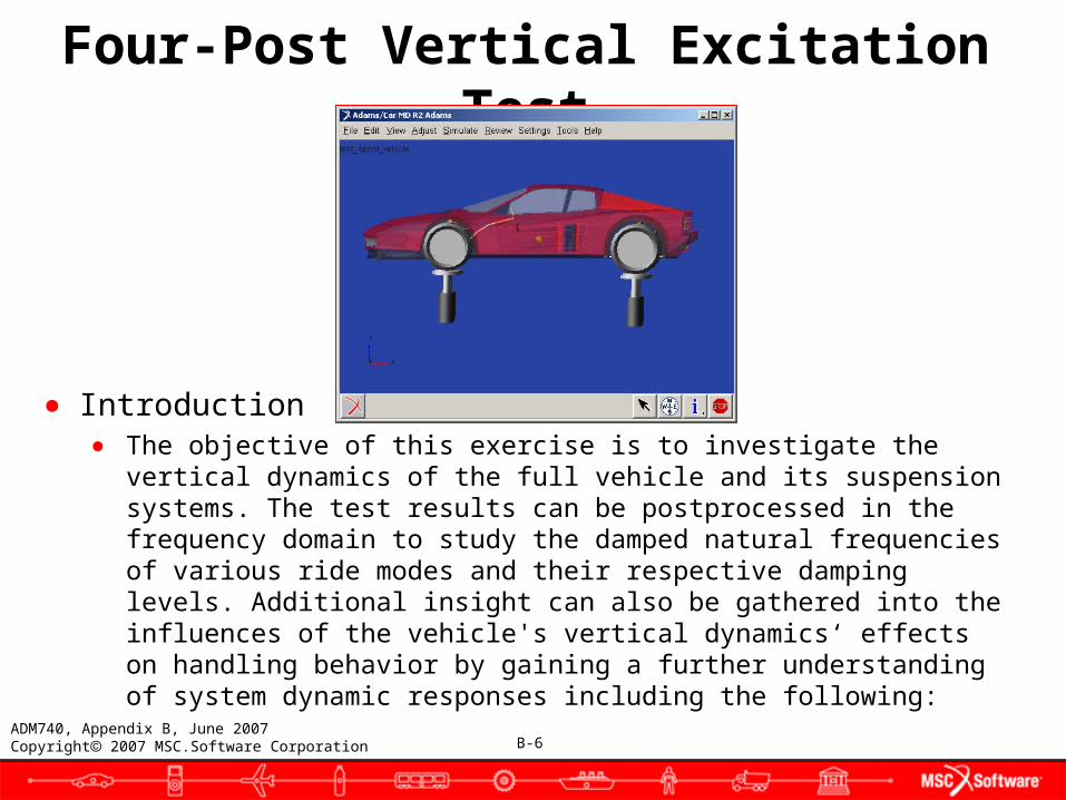
● Introduction● The objective of this exercise is to investigate the vertical
dynamics of the full vehicle and its suspension systems. The test results can be postprocessed in the frequency domain to study the damped natural frequencies of various ride modes and their respective damping levels. Additional insight can also be gathered into the influences of the vehicle's vertical dynamics‘ effects on handling behavior by gaining a further understanding of system dynamic responses including the following:

B-7ADM740, Appendix B, June 2007Copyright 2007 MSC.Software Corporation
Four-Post Vertical Excitation Test
● Front to rear modal balance● Suspension to body transfer function gain and phase● Suspension to tire transfer function gain and phase● Tire contact patch vertical load variation
● The test is conducted by assembling a standard full-vehicle model to a special four-post test rig. The test rig is simply defined by four parts representing the tire pads that support the vehicle. These tire pads are constrained to move in only the vertical direction and a displacement actuator (motion controller) controls their vertical motion. The only constraint between the pads and the vehicle's tires is the friction of the tire itself. Because the Delft tire model supports zero velocity tire friction, this is all that is required to constrain the vehicle during the dynamic portion of the simulation.
B-8ADM740, Appendix B, June 2007Copyright 2007 MSC.Software Corporation
Four-Post Vertical Excitation Test
● The vertical actuators are each controlled by an analytical function. The analytical functions are used to describe the displacement profile of the actuator in the time domain and they are limited to constant amplitude sinusoidal input that sweeps over a predetermined frequency range in a set amount of time. When using the analytical function control there exist four excitation modes described below:
● Heave: all tire pads move vertically in phase.● Pitch: the front tire pads move 180 degrees out of phase with the rear
tire pads.● Roll: the left tire pads move 180 degrees out of phase with the right
tire pads.● Warp: the left-front and right-rear tire pads move 180 degrees out of
phase with the right-front and left-rear pads.
B-9ADM740, Appendix B, June 2007Copyright 2007 MSC.Software Corporation
Four-Post Vertical Excitation Test
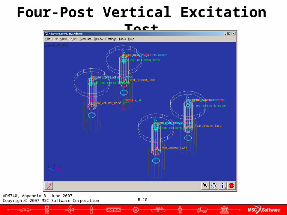
● Test rig description● The four-post test rig was created in Adams/Car Template Builder
and is named __acme_4PostRig.tpl. What follows is a brief description of how it works and how it relates to the standard Adams/Car simulation types. The major role of the four-post test rig template is analysis and it contains four general parts. There are four tire pads and four actuators for each of the vertical translation joints on each pad. The location of all of the pads and their respective constraints, actuators, and so on, are parameterized in the ground plane (X and Y) to a wheel center location communicator that comes from the suspension systems. The vertical location is parameterized to the Z location of the std_tire_ref marker. The std_tire_ref marker has its Z height set automatically during the assembly process so that it represents the vehicles average tire contact patch height.
B-10ADM740, Appendix B, June 2007Copyright 2007 MSC.Software Corporation
Four-Post Vertical Excitation Test
B-11ADM740, Appendix B, June 2007Copyright 2007 MSC.Software Corporation
Four-Post Vertical Excitation Test
● User input requirements: simulation description● The analysis input parameters are grouped in two categories: one
group of parameters is common to all analyses, while the other group consists of input specific to this four-post test. The four-post simulation input requirements are controlled by the user in order to define the boundary conditions of the desired vertical excitation test.
● Always required:● Output Prefix● End Time● Number of Steps● Type of Analysis (Interactive, Background)● Analysis Log File (Yes, No)
● Four-post simulation input requirements:● Peak Displacement● Displacement Units (m, mm, inch, and so on)● Frequency Range (Units hardcoded to Hz)● Excitation Mode (Heave, Pitch, Roll, Warp)
B-12ADM740, Appendix B, June 2007Copyright 2007 MSC.Software Corporation
Four-Post Vertical Excitation Test
● Assembly and simulation process requirements● The following steps outline what the test rig simulation process is
doing internally after a simulation has been requested. The vehicle/test rig assembly process is similar regardless of the user input parameters outlined in the previous section of the document. However, the modifications made to the assembled model will vary depending on these parameters.
● Assembly process:1. Same subsystem level check as in any full-vehicle maneuver with
possibly an extra check to ensure there are no more then four wheels and two suspensions.
2. Assemble vehicle with test rig. Location communicators will locate the pads in the X and Y plane.
3. Loop over the tires and reassign the GFORCE reference markers to the appropriate respective pad. The left front tire's reference marker needs to belong to the gel_front_pad part of the test rig, for example.
B-13ADM740, Appendix B, June 2007Copyright 2007 MSC.Software Corporation
Four-Post Vertical Excitation Test
4. Assign the Z location of the std_tire_ref marker based on the average contact patch location of all of the tires (the same as it is done in a full-vehicle simulation).
5. Set the tire property file to a hardcoded value of mdi_2d_flat.rdf for each of the tires without generating any road geometry.
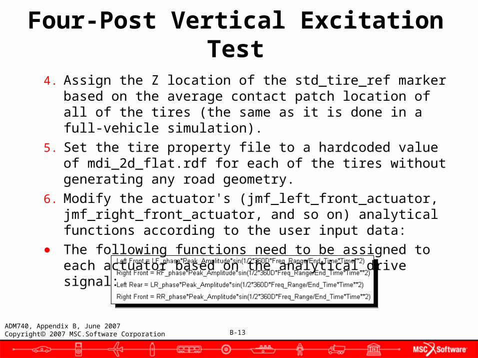
6. Modify the actuator's (jmf_left_front_actuator, jmf_right_front_actuator, and so on) analytical functions according to the user input data:
● The following functions need to be assigned to each actuator based on the analytical drive signal:
B-14ADM740, Appendix B, June 2007Copyright 2007 MSC.Software Corporation
Four-Post Vertical Excitation Test
● Where the following values are assigned to the phase variables:● Heave Mode: LF_Phase, RF_Phase, LR_Phase, RR_Phase = 1.0● Pitch Mode: LF_Phase, RF_Phase = 1.0 & LR_Phase, RR_Phase = -
1.0● Roll Mode: LF_Phase, LR_Phase = 1.0 & RF_Phase, RR_Phase = -1.0● Warp Mode: LF_Phase, RR_Phase = 1.0 & RF_Phase, LR_Phase = -
1.0
● The test rig then goes through the following simulation process:● Submit the simulation to the solver using a similar process as the full-
vehicle simulation. The simulation needs one static equilibrium, an initial velocity = 0.0, and then a dynamic simulation equal to the end. The hmax on the integrator should also be set to at least 1/10 of the maximum frequency range. For example, if the frequency range set by the user is 20Hz then the hmax should be 1/10*1/20 = 1/200 (0.005). This is necessary to avoid aliasing of the input during the simulation.

B-15ADM740, Appendix B, June 2007Copyright 2007 MSC.Software Corporation
Four-Post Vertical Excitation Test
● Creating a test rig template in Adams/Car● A minimum prerequisite for the task of adding a test rig to
Adams/Car is a thorough understanding of all aspects of Adams/Car Template Builder. It is very important that users attempting to create test rigs in Adams/Car have a firm understanding of the concepts of communicators and actuators. As you work through this section, you should reference the Templates tab in the Adams/Car online help. It might also be beneficial to examine the test rigs that are included in standard Adams/Car.
● A test rig in Adams/Car is almost completely comparable to a template in Adams/Car. Test rigs differ from templates mainly because test rigs contain actuator elements, such as motions and
forces, to excite the assembly.
B-16ADM740, Appendix B, June 2007Copyright 2007 MSC.Software Corporation
Four-Post Vertical Excitation Test
● The procedure for creating a test rig template in Adams/Car is just like the procedure of creating a normal template, with a few differences. The steps for creating a test rig template are:
● Creating a test rig template● Saving the test rig template● Modifying the test rig template
● Getting started● A test rig template is created in the template builder in Adams/Car.
Like a regular template, a test rig template can contain parts attached together via attachments and forces. Unlike most templates, the test rig template will also contain actuators to excite the system. The test rig template, like normal templates, will also contain communicators to enable the exchange of information with other templates.
B-17ADM740, Appendix B, June 2007Copyright 2007 MSC.Software Corporation
Four-Post Vertical Excitation Test
● Because templates and test rigs are so similar, it would be redundant to fully describe how to create test rigs. Instead, for specific information about building templates and communicators, see the Templates tab in the Adams/Car online help.
● Adams/Car works with test rigs as templates. However, in order to incorporate a test rig for use on an assembly, the test rig must be converted to a test rig model file (.cmd) and a private Adams/Car binary created. You can, of course, create a new test rig template from the Adams/Car interface very easily, but it is often best to work with existing templates in order to better understand the capabilities of MD R2 Adams.
● You start by modifying an existing test rig model file (.cmd) in the template builder. Start by locating the file acme_3PostRig.cmd. This is a test rig model file (.cmd) that contains a test rig currently equipped with three active posts.

B-18ADM740, Appendix B, June 2007Copyright 2007 MSC.Software Corporation
Four-Post Vertical Excitation Test
● Loading a test rig model file (.cmd) into the Adams/Car Template Builder● If you want to open an existing test rig model (.cmd) file and edit it
using Adams/Car Template Builder, follow the steps outlined in this section. Try these steps out on the acme_3postrig.cmd file. Note that you should be careful if using a private or site Adams/Car binary when editing a test rig template. If you already made a test rig and a private binary incorporating it, you cannot edit the test rig of the same name.
B-19ADM740, Appendix B, June 2007Copyright 2007 MSC.Software Corporation
Four-Post Vertical Excitation Test
● To load a test rig model file:1. Move the test rig model file, acme_3postrig.cmd file, to your
private car database under the templates table (for example, C:\private.cdb\templates.tbl\).
2. Rename the file from acme_3postrig.cmd to _acme_4PostRig.tpl. Make sure that you precede the template name with two underscores (__).
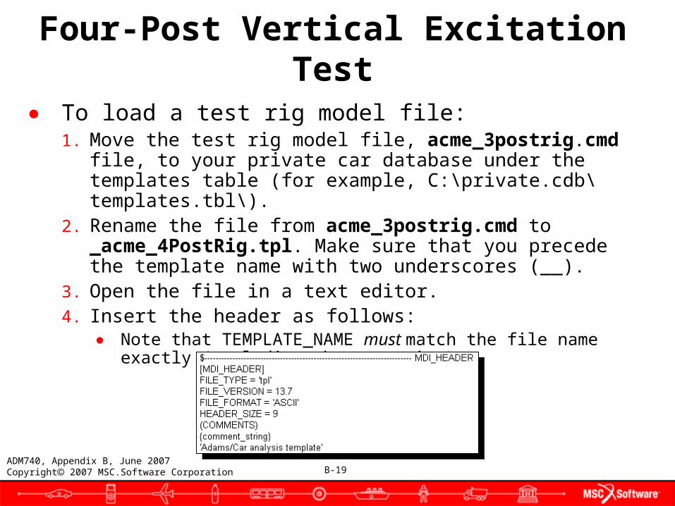
3. Open the file in a text editor.4. Insert the header as follows:
● Note that TEMPLATE_NAME must match the file name exactly (excluding the extension).
B-20ADM740, Appendix B, June 2007Copyright 2007 MSC.Software Corporation
● Tip: You can copy the text from the file four_post_header.txt, located in four_post_test_rig_files, and paste it into your file.
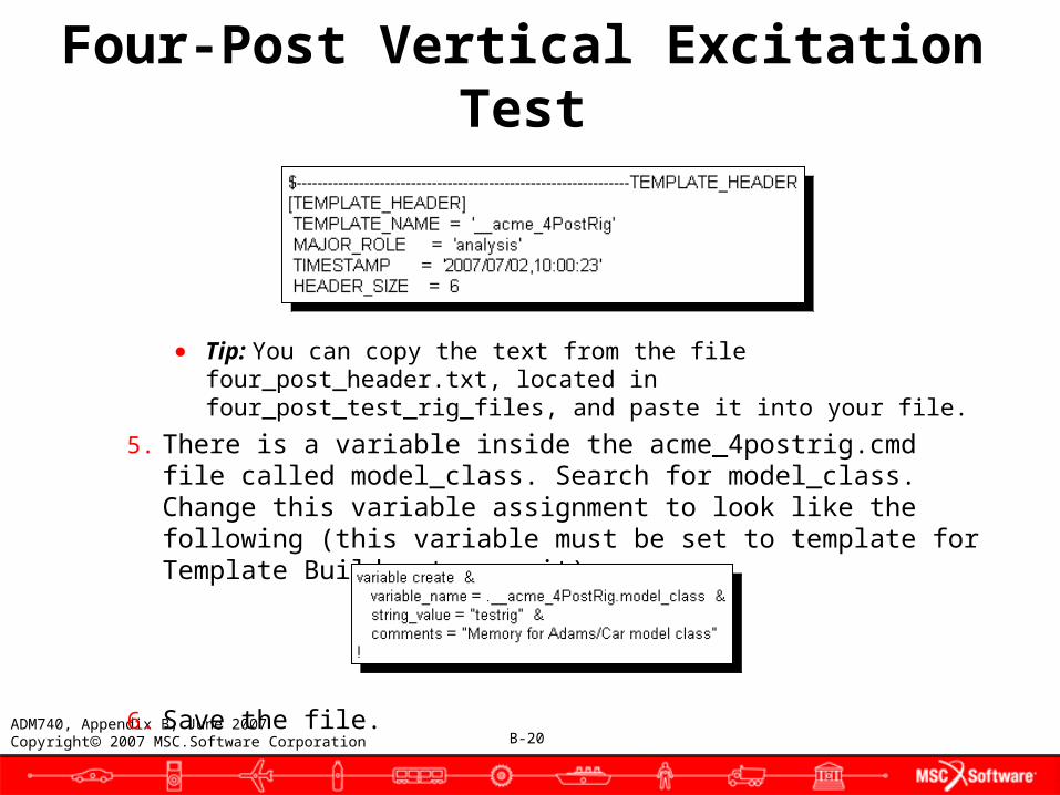
5. There is a variable inside the acme_4postrig.cmd file called model_class. Search for model_class. Change this variable assignment to look like the following (this variable must be set to template for Template Builder to use it):
6. Save the file.
Four-Post Vertical Excitation Test
B-21ADM740, Appendix B, June 2007Copyright 2007 MSC.Software Corporation
Four-Post Vertical Excitation Test
● Opening the test rig in Adams/Car Template Builder● The file that you just specified as an Adams/Car template contains a
model of a test rig with only three active posts. In this section, you activate the fourth (left-front) post.
● To open the test rig:1. Make sure that your .acar.cfg file specifies you as an expert user so
you can start the Adams/Car Template Builder.2. Start Adams/Car and select the template-builder mode at the prompt.3. From the File menu, select Open.4. Right-click the Template Name text box, point to Search, and then
select <private>/ templates.tbl.5. Select the __acme_4PostRig.tpl template file, and then select OK
twice.6. Make sure icon visibility is on, the view is set to Front Iso and the view
is zoomed to fit.

B-22ADM740, Appendix B, June 2007Copyright 2007 MSC.Software Corporation
Four-Post Vertical Excitation Test
● Modifying the test rig in Adams/Car Template Builder● To make the actuator active, you will add a variety of items to the
test rig: a bumpstop, a reboundstop, a joint attachment, a joint motion actuator, and a joint force actuator.
● To add a bumpstop:1. From the Build menu, point to Forces, point to Bumpstop, and
then select New.
2. In the Bumpstop Name text box, enter front_extension_stop.
3. Specify the I Part as gel_front_pad by typing it in or by right-clicking the text box, pointing to Part, selecting Pick, and then choosing the part gel_front_pad.
4. Specify the J Part as ground by right-clicking the text box, pointing to Guesses, and then selecting ground.

B-23ADM740, Appendix B, June 2007Copyright 2007 MSC.Software Corporation
Four-Post Vertical Excitation Test
5. Specify the I Coordinate Reference as cfl_Front_Actuator_Base.
6. Specify the J Coordinate Reference as cfl_Front_Pad.
7. Ensure that the Property File text box specifies <shared>\bumpstops.tbl\mdi_0001.bum as the property file.
8. In the Clearance text box, enter 127.
9. Select OK.
Note that because of symmetry relations, not only is a bumpstop immediately created on the left front actuator base, but one is also created on the right front.
B-24ADM740, Appendix B, June 2007Copyright 2007 MSC.Software Corporation
Four-Post Vertical Excitation Test
● To create a reboundstop:1. From the Build menu, point to Forces, point to Reboundstop, and
then select New.2. In the Reboundstop Name text box, enter front_retract_stop to
enforce a consistent naming convention.3. Set I Part to gel_front_pad.4. Set J Part to ground.5. Set I Coordinate Reference to cfl_Front_Actuator_Base.6. Set J Coordinate Reference to cfl_front_pad.7. Ensure that the Property File text box points to <shared>\
reboundstops.tbl\mdi_0001.reb.8. In the Clearance text box, enter 127.9. Select OK.
Note that because of symmetry relations, not only is a reboundstop immediately created on the left front actuator base, but one is also created on the right front.
B-25ADM740, Appendix B, June 2007Copyright 2007 MSC.Software Corporation
Four-Post Vertical Excitation Test
● To add an attachment between the actuator pad and actuator base:1. From the Build menu, point to Attachments, point to Joint, and
then select New.
2. Specify the Joint Name as left_front_pad.
3. Specify the I Part as ground.
4. Specify the J Part as gel_front_pad.
Note: The I and J part order is important to determine direction for the joint motion actuator defined next.
5. Set the Type to single.
6. Set Joint Type to translational.
B-26ADM740, Appendix B, June 2007Copyright 2007 MSC.Software Corporation
Four-Post Vertical Excitation Test
7. Set Location Dependency to Delta location from coordinate.
8. Set Location Coordinate Reference to cfl_front_pad.
9. Set Location to 0,0,0 in local.
10. Set Orientation Dependency to Delta orientation from coordinate.
11. Set Construction Frame to cfl_front_pad.
12. Set Orientation to 0,0,0.
13. Select OK.

B-27ADM740, Appendix B, June 2007Copyright 2007 MSC.Software Corporation
Four-Post Vertical Excitation Test
● To make the joint motion actuator:1. From the Build menu, point to Actuators, point to Joint Motion,
and then select New.
2. Specify the Actuator Name as left_front_actuator to enforce consistent naming.
3. Specify the joint as jostra_left_front_pad by picking the joint you just created.
4. In the Application text box, enter pad_excitation.
5. In the Identifier text box, enter left_front_actuator.
6. In the Function text box, enter 15*sin(720d*time). This is a dummy function that the analysis macro will overwrite.
7. Specify the Time Derivative as displacement.
B-28ADM740, Appendix B, June 2007Copyright 2007 MSC.Software Corporation
Four-Post Vertical Excitation Test
8. Set the Force Limits to -5e4,5e4.
9. Set the Displacement Limits to -1000,1000.
10. Set the Velocity Limits to -1e4,1e4.
11. Set the Acceleration Limits to -9.8e4,9.8e4.
12. In the Units text box, enter mm.
13. Select OK.
B-29ADM740, Appendix B, June 2007Copyright 2007 MSC.Software Corporation
Four-Post Vertical Excitation Test
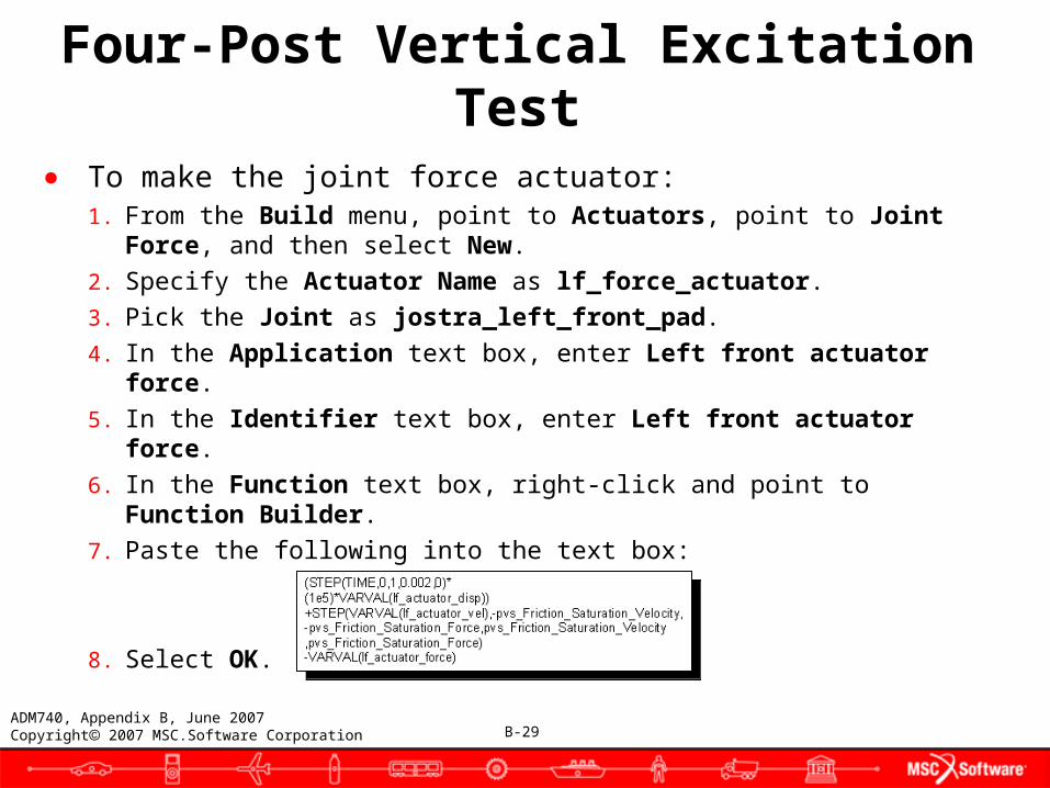
● To make the joint force actuator:1. From the Build menu, point to Actuators, point to Joint Force,
and then select New.
2. Specify the Actuator Name as lf_force_actuator.
3. Pick the Joint as jostra_left_front_pad.
4. In the Application text box, enter Left front actuator force.
5. In the Identifier text box, enter Left front actuator force.
6. In the Function text box, right-click and point to Function Builder.
7. Paste the following into the text box:
8. Select OK.
B-30ADM740, Appendix B, June 2007Copyright 2007 MSC.Software Corporation
Four-Post Vertical Excitation Test
● Saving the test rig template● The test rig template is saved to a file just like a regular template.
The test rig template should be saved in an ASCII format to facilitate the modifications that are required and described in the next section.
● To save the template:1. From the File menu, select Save As.
2. Make sure the file format is set to ASCII, and that Zero Adams Ids is selected.
3. Select Close Template.
4. Select OK, don't save a backup copy when prompted.
B-31ADM740, Appendix B, June 2007Copyright 2007 MSC.Software Corporation
Four-Post Vertical Excitation Test
● Making a test rig model file (.cmd) from an Adams/Car template● You must manually modify the file of the test rig template to make
it into a test rig model file (.cmd). There are two modifications that you must do to the ASCII template file generated from Adams/Car.
● If you want to take a test rig built in the template builder and then use it as a test rig, you should basically perform the steps in Loading a test rig model file (.cmd) into the Adams/Car Template Builder, on slide 18 in reverse order.
B-32ADM740, Appendix B, June 2007Copyright 2007 MSC.Software Corporation
Four-Post Vertical Excitation Test
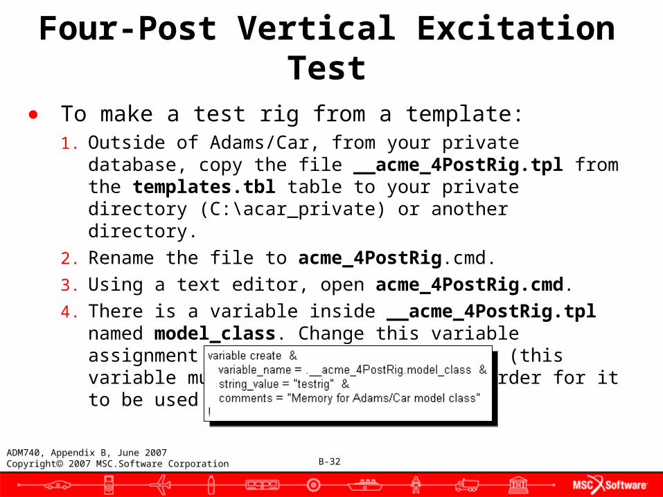
● To make a test rig from a template:1. Outside of Adams/Car, from your private database, copy the file
__acme_4PostRig.tpl from the templates.tbl table to your private directory (C:\acar_private) or another directory.
2. Rename the file to acme_4PostRig.cmd.
3. Using a text editor, open acme_4PostRig.cmd.
4. There is a variable inside __acme_4PostRig.tpl named model_class. Change this variable assignment to look like the following (this variable must be set to test rig in order for it to be used as one):
B-33ADM740, Appendix B, June 2007Copyright 2007 MSC.Software Corporation
5. Remove the header information that is added at the beginning of the ASCII template file. This header must be removed because the command file reader will not understand the information stored in this header and will output errors. A typical header from an ASCII was shown in Loading a test rig model file (.cmd) into the Adams/Car Template Builder, on slide 18.
6. Remove all the lines from the beginning of the file up to and including the line containing the HEADER_SIZE attribute.
7. Save the file.
Four-Post Vertical Excitation Test
B-34ADM740, Appendix B, June 2007Copyright 2007 MSC.Software Corporation
Four-Post Vertical Excitation Test
● Adams/View variables required in a test rig● Templates and test rigs in Adams/Car have information that is
stored in Adams/View variables to determine how the template is used. All templates, including test rigs have three required variables: major role, minor role, and model class. Test rigs have an additional Adams/View variable named assembly class.
● All the variables required in a test rig are described below. The first three variables: role, minor_role, and model_class are all created automatically when the test rig template is created. You must manually create the variable testrig_class, which is unique to test rigs, as described above.
B-35ADM740, Appendix B, June 2007Copyright 2007 MSC.Software Corporation
Four-Post Vertical Excitation Test
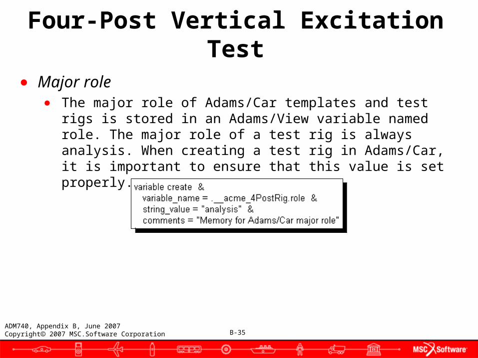
● Major role● The major role of Adams/Car templates and test rigs is stored in
an Adams/View variable named role. The major role of a test rig is always analysis. When creating a test rig in Adams/Car, it is important to ensure that this value is set properly.
B-36ADM740, Appendix B, June 2007Copyright 2007 MSC.Software Corporation
Four-Post Vertical Excitation Test
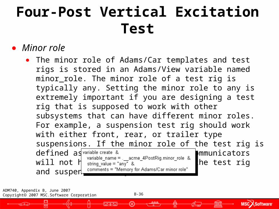
● Minor role● The minor role of Adams/Car templates and test rigs is stored in
an Adams/View variable named minor_role. The minor role of a test rig is typically any. Setting the minor role to any is extremely important if you are designing a test rig that is supposed to work with other subsystems that can have different minor roles. For example, a suspension test rig should work with either front, rear, or trailer type suspensions. If the minor role of the test rig is defined as any in this case, the communicators will not hook up properly between the test rig and suspension subsystem.
B-37ADM740, Appendix B, June 2007Copyright 2007 MSC.Software Corporation
Four-Post Vertical Excitation Test
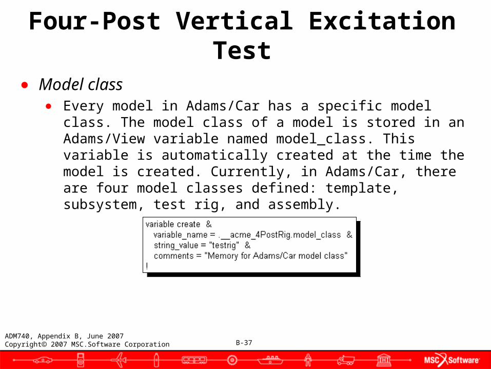
● Model class● Every model in Adams/Car has a specific model class. The model
class of a model is stored in an Adams/View variable named model_class. This variable is automatically created at the time the model is created. Currently, in Adams/Car, there are four model classes defined: template, subsystem, test rig, and assembly.

B-38ADM740, Appendix B, June 2007Copyright 2007 MSC.Software Corporation
Four-Post Vertical Excitation Test
● Test rig class● All test rigs in Adams/Car can be associated with a particular class
of assembly. For example, the __MDI_SUSPENSION_TESTRIG test rig is associated with suspension assemblies. The test rig class of a test rig is stored in an Adams/View variable called testrig_class.
● The testrig_class variable is used directly in the graphical user interface. For example, this variable is used in the new suspension assembly and new full-vehicle assembly dialog boxes. These two dialog boxes each contain an option menu from which you select the test rig to be included in the new assembly. This option menu will only contain test rigs that are compatible with that class of assembly. The option menu on the new suspension assembly dialog box, for example, will only list those test rigs that have a test rig class of suspension.
B-39ADM740, Appendix B, June 2007Copyright 2007 MSC.Software Corporation
Four-Post Vertical Excitation Test● Preparing to create a private binary
● You can now add both your new test rig model file acme_4PostRig.cmd) and the macro files attached to this tutorial to build a custom private Adams/Car binary which can implement this new test rig. The process of creating private and site binary files is outlined next:
1. If the directory does not exist, create a directory C:\acar_private (MD R2 Adams always looks for $HOME\acar_private when running a private binary, unless MDI_ACAR_PRIVATE explicity sets this otherwise).
2. In this directory, copy these five ASCII files into C:\acar_private:● acar_build.cmd● acme_4postrig.cmd● macros_ana.cmd● mac_ana_ful_fou_sub.cmd● acme_four_sim.cmd
● A description of each of these follows:acar_build.cmd
B-40ADM740, Appendix B, June 2007Copyright 2007 MSC.Software Corporation
Four-Post Vertical Excitation Test
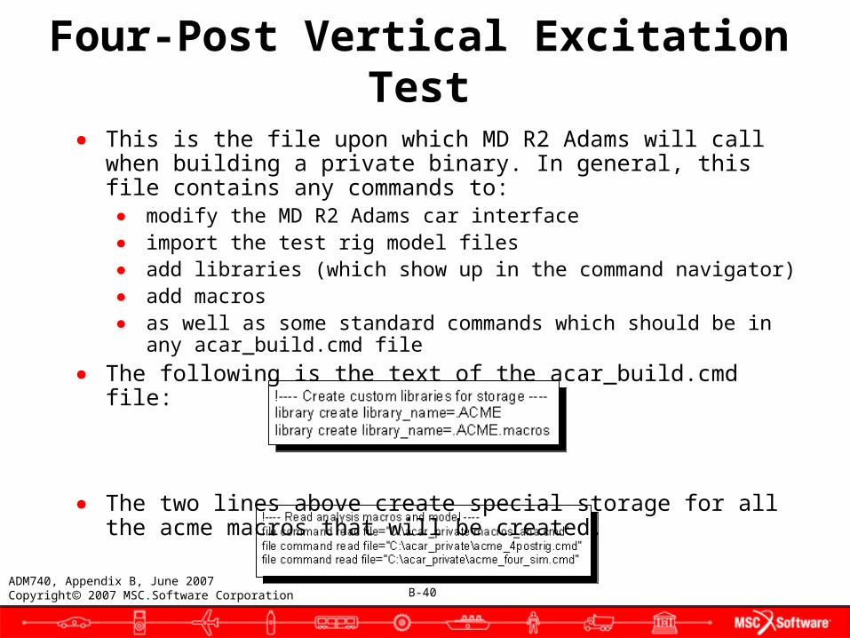
● This is the file upon which MD R2 Adams will call when building a private binary. In general, this file contains any commands to:
● modify the MD R2 Adams car interface● import the test rig model files● add libraries (which show up in the command navigator)● add macros● as well as some standard commands which should be in any
acar_build.cmd file● The following is the text of the acar_build.cmd file:
● The two lines above create special storage for all the acme macros that will be created.
B-41ADM740, Appendix B, June 2007Copyright 2007 MSC.Software Corporation
Four-Post Vertical Excitation Test
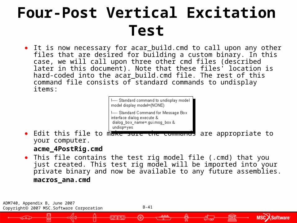
● It is now necessary for acar_build.cmd to call upon any other files that are desired for building a custom binary. In this case, we will call upon three other cmd files (described later in this document). Note that these files' location is hard-coded into the acar_build.cmd file. The rest of this command file consists of standard commands to undisplay items:
● Edit this file to make sure the commands are appropriate to your computer.
acme_4PostRig.cmd● This file contains the test rig model file (.cmd) that you just created.
This test rig model will be imported into your private binary and now be available to any future assemblies.
macros_ana.cmd
B-42ADM740, Appendix B, June 2007Copyright 2007 MSC.Software Corporation
Four-Post Vertical Excitation Test
● This file serves as a pointer to mac_ana_ful_fou_sub.cmd. It contains a hard-coded file location. It is good practice to use pointers like this rather than to import the simulation macros themselves. This allows for easy modification.
● Edit this file to make sure the commands are appropriate to your computer.
mac_ana_ful_fou_sub.cmd● This is a macro that instructs Adams/Car on how to simulate the
model. This file is discussed in depth in Adding custom analysis procedures to Adams/Car, on slide 58.
acme_four_sim.cmd● This is a custom dialog box modification, which also adds a special
Acme Four Post Simulation item under the Tools menu. This was built with a text editor, and is commented. The commands that make the menu items appear at the end of the file. It is easy to create your own dialog boxes and menus, but it is often helpful to have a file like this for reference.
B-43ADM740, Appendix B, June 2007Copyright 2007 MSC.Software Corporation
Four-Post Vertical Excitation Test
● Adding the four-post analysis to a private binary● To create the private binary:
1. Do one of the following:● Windows: From the Start menu, point to Programs, point to
MSC.Software, point to MD R2 Adams, point to ACar, and then select Advanced. At the prompt, enter cr-privatebin.
● UNIX: In a shell window, enter Adamsmdr2 -c acar cr-privatebin.
2. Check the acar.log file for information/errors on building the acar.bin file.
B-44ADM740, Appendix B, June 2007Copyright 2007 MSC.Software Corporation
Four-Post Vertical Excitation Test
● Running Adams/Car with a private binary
To run Adams/Car with your private binary:
● On Windows:● From the Start menu, point to Programs, point to MSC.Software,
point to MD R2 Adams, point to A/Car, and then select Advanced. At the prompt, enter ru-private.
● You could also create a shortcut to this containing the path:
C:\Program Files\Adams mdr2\common\mdi.bat acar ru-private.
Note: When you want to build a binary with a second test rig later, you will have to make sure that acar_build.cmd calls both your new files and these old files!
● On UNIX:● In a shell window, enter Adamsmdr2 -c acar ru-private.
B-45ADM740, Appendix B, June 2007Copyright 2007 MSC.Software Corporation
Four-Post Vertical Excitation Test
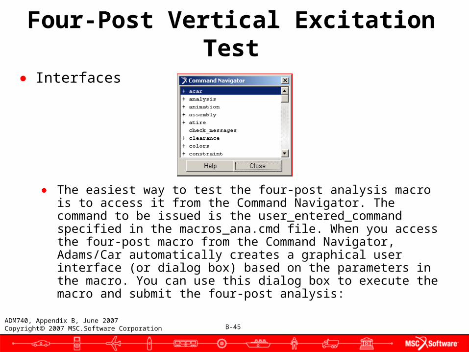
● Interfaces
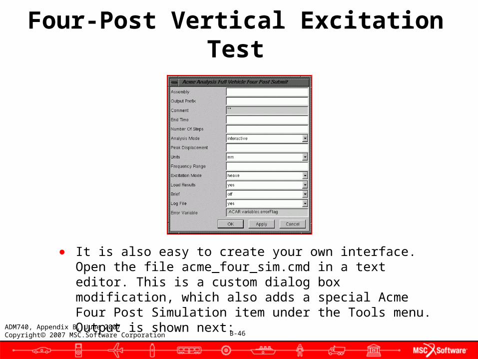
● The easiest way to test the four-post analysis macro is to access it from the Command Navigator. The command to be issued is the user_entered_command specified in the macros_ana.cmd file. When you access the four-post macro from the Command Navigator, Adams/Car automatically creates a graphical user interface (or dialog box) based on the parameters in the macro. You can use this dialog box to execute the macro and submit the four-post analysis:
B-46ADM740, Appendix B, June 2007Copyright 2007 MSC.Software Corporation
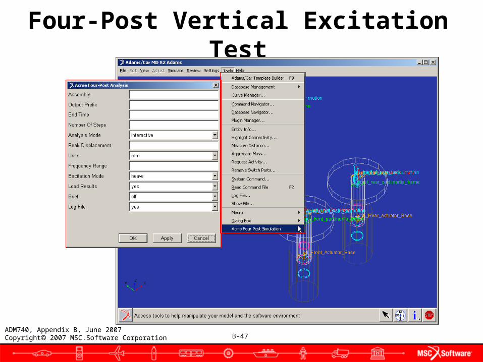
● It is also easy to create your own interface. Open the file acme_four_sim.cmd in a text editor. This is a custom dialog box modification, which also adds a special Acme Four Post Simulation item under the Tools menu. Output is shown next:
Four-Post Vertical Excitation Test
B-47ADM740, Appendix B, June 2007Copyright 2007 MSC.Software Corporation
Four-Post Vertical Excitation Test
B-48ADM740, Appendix B, June 2007Copyright 2007 MSC.Software Corporation
Four-Post Vertical Excitation Test
● Creating an assembly using the test rig● At this point you should have made a test rig template, test rig
model file (.cmd), analysis macro, private binary, and custom interface. You are now ready to run a four-post simulation on a full-vehicle assembly.
● To create an assembly:● On Windows:
1. Start Adams/Car with your private binary by selecting Start -> Programs -> MSC.Software -> MD R2 Adams -> ACar -> Advanced.
2. At the prompt, enter ru-private. Continue with step 4.
B-49ADM740, Appendix B, June 2007Copyright 2007 MSC.Software Corporation
Four-Post Vertical Excitation Test
● On UNIX:3. At the prompt, enter adamsmdr2 -c acar ru-private i. Continue with
step 4.4. Make sure you select Standard Interface if Adams/Car prompts you
about which interface you want to use.5. From the File menu, point to New, and then select Full-Vehicle
Assembly.6. In the Assembly Name text box, enter test_4post_vehicle.7. Right-click the Front Susp Subsystem text box, point to Search, point to
<shared>/subsystems.tbl and left-click to open a selection window with the various available vehicle subsystems displayed. Select TR_Front_Suspension.sub.
8. Right-click the Rear Susp Subsystem text box, and follow the instructions above to select TR_Rear_Suspension.sub.
9. In the Steering Subsystem text box, select TR_Steering.

B-50ADM740, Appendix B, June 2007Copyright 2007 MSC.Software Corporation
Four-Post Vertical Excitation Test
10. In the Front Wheel Subsystem text box, select TR_Front_Tires.sub.
11. In the Rear Wheel Subsystem text box, select TR_Rear_tires.sub.
12. In the Body Subsystem text box, select TR_Body.sub.
13. Make sure that Powertrain Subsystem is not selected.
14. Make sure that Brake Subsystem is not selected.
15. Set Vehicle Test Rig to __acme_4PostRig.
16. Select OK.
It will take some time for the assembly to complete.
B-51ADM740, Appendix B, June 2007Copyright 2007 MSC.Software Corporation
Four-Post Vertical Excitation Test
● To switch the tire model to Delft:1. Right-click the mouse on the vehicle's left-front wheel, point to
Wheel:whl_wheel, and then select Modify.
2. Change the Property File to <shared>\tires.tbl\mdi_delft01.tir.
3. Select OK.
4. Right-click the mouse on the vehicle's left-rear wheel, point to Wheel:whl_wheel, and then select Modify.
5. Change the Property File to <shared>\tires.tbl\mdi_delft01.tir.
6. Select OK.
B-52ADM740, Appendix B, June 2007Copyright 2007 MSC.Software Corporation
Four-Post Vertical Excitation Test
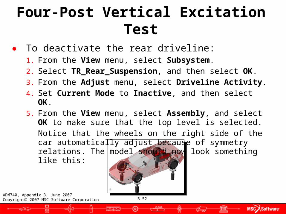
● To deactivate the rear driveline:1. From the View menu, select Subsystem.2. Select TR_Rear_Suspension, and then select OK.3. From the Adjust menu, select Driveline Activity.4. Set Current Mode to Inactive, and then select OK.5. From the View menu, select Assembly, and select OK to make
sure that the top level is selected.Notice that the wheels on the right side of the car automatically adjust because of symmetry relations. The model should now look something like this:
B-53ADM740, Appendix B, June 2007Copyright 2007 MSC.Software Corporation
Four-Post Vertical Excitation Test
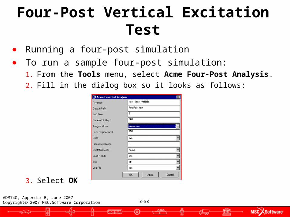
● Running a four-post simulation● To run a sample four-post simulation:
1. From the Tools menu, select Acme Four-Post Analysis.
2. Fill in the dialog box so it looks as follows:
3. Select OK
B-54ADM740, Appendix B, June 2007Copyright 2007 MSC.Software Corporation
Four-Post Vertical Excitation Test
● The simulation will take some time to run.● To review the animation:
1. From the Review menu, select Animation Controls.
2. Press the Play tool.
You can also review the plots of simulation results in Adams/PostProcessor. When done, return to Adams/Car by selecting Exit.
You should now save this assembly and exit.
● To save the assembly and exit:1. From the File menu, point to Save, and then select Assembly.
2. Select Close assembly after save.
3. Select OK.
Adams/Car saves this assembly in your private database.
B-55ADM740, Appendix B, June 2007Copyright 2007 MSC.Software Corporation
Four-Post Vertical Excitation Test
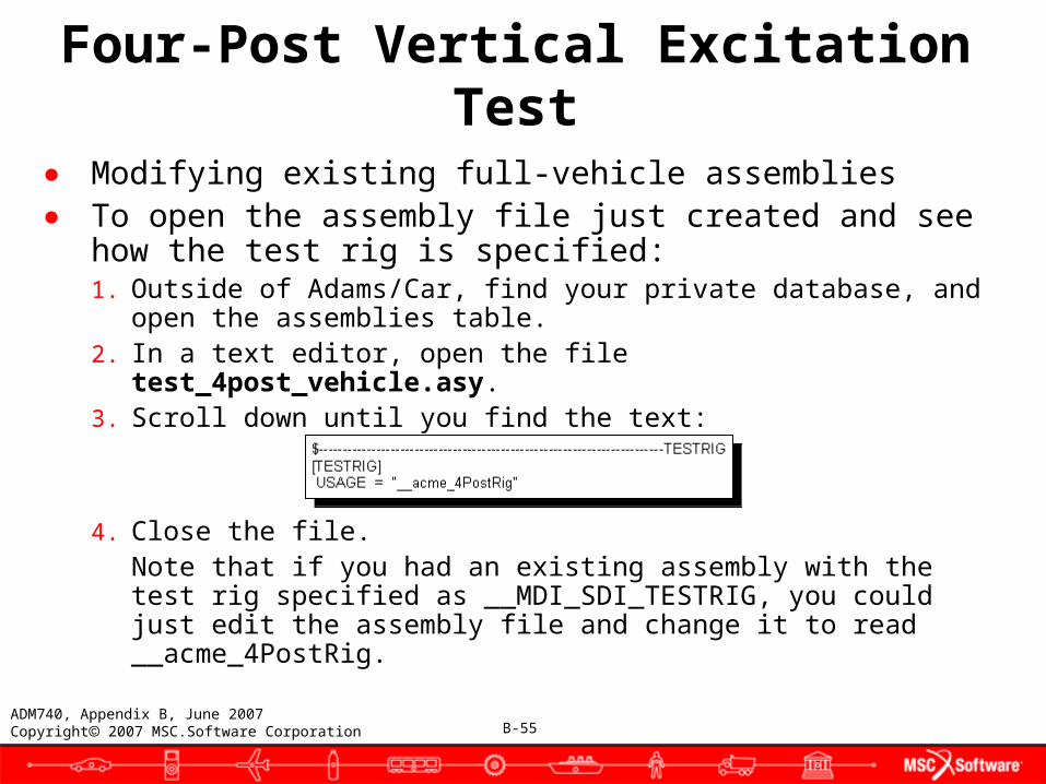
● Modifying existing full-vehicle assemblies● To open the assembly file just created and see how the
test rig is specified:1. Outside of Adams/Car, find your private database, and open the
assemblies table.2. In a text editor, open the file test_4post_vehicle.asy.3. Scroll down until you find the text:
4. Close the file.Note that if you had an existing assembly with the test rig specified as __MDI_SDI_TESTRIG, you could just edit the assembly file and change it to read __acme_4PostRig.
B-56ADM740, Appendix B, June 2007Copyright 2007 MSC.Software Corporation
Four-Post Vertical Excitation Test
● Adding custom analysis procedures to Adams/Car● A minimum prerequisite of adding an analysis to Adams/Car is a
thorough understanding of the Adams/View macro language. As you work through this section, you should reference the Customize tab in the Adams/Car online help.
● Adams/Car is designed with an open architecture to facilitate extensions based on customer requirements. Most often users desire to extend the analysis capabilities of Adams/Car to include an analysis type or maneuver that is typical within their company, but not included in the Adams/Car product. All analyses in Adams/Car are defined using macros. Therefore, adding a new analysis to Adams/Car can be as simple as adding a new macro. A custom graphical interface to the new macro may also be created to facilitate usage, but is not required.
● This example will provide you with step-by-step instructions to create your own macro from a given user scenario. The objective of the analysis is described in detail in the attached Four-Post Vertical Excitation Test document.
B-57ADM740, Appendix B, June 2007Copyright 2007 MSC.Software Corporation
Four-Post Vertical Excitation Test
● Getting started● The best way to get started creating a new analysis is not to start
from scratch. There is a broad range of analyses that are possible within the Adams/Car product as it is shipped. Examine the existing functionality to find an analysis that closely suites the analysis you want. Once you have selected an existing macro, simply modify it to suite your needs.
● You can view any of the standard macros using the macro editor inside Adams/Car. From the Adams/Car menu, choose Tools -> Macro -> Edit -> Modify to open the Database Navigator. Then, select the macro you want to display. Selecting mac_ana_ful_fou_sub from the Database Navigator, for example, will allow you to view the standard macro for submitting a full-vehicle four-post analysis.For more information on macros in Adams/Car, see the Customize tab in the Adams/Car online help.
B-58ADM740, Appendix B, June 2007Copyright 2007 MSC.Software Corporation
Four-Post Vertical Excitation Test
● Where possible, existing utility macros should be used in custom analysis macros. Using the existing utilities macros shipped within Adams/Car has a few benefits. First, these macros are already written and tested by MSC.Software. Second, using these macros reduces the amount of work required to add a custom analysis to Adams/Car. Third, these macros provide a common basis for customization, facilitating maintenance and debugging between different projects.
● Analysis macro structure● In general, all the analysis macros within Adams/Car are structured
the same. This is especially true if you are looking only at a particular class of analysis macros. For example, all the open-loop full-vehicle analysis macros are surprisingly similar. The same holds true for all the full-vehicle analysis macros based on the Driving Machine. Typically, a small section within a macro is what makes that macro and the resulting analysis unique. Every analysis macro in Adams/Car has the same basic structure.
B-59ADM740, Appendix B, June 2007Copyright 2007 MSC.Software Corporation
Four-Post Vertical Excitation Test
● Parameter definition● Parameters are the means by which the end user inputs values
into the macro. They are placeholders for information that the end user provides when the macro is executed.
Macro parameters are described in detail in the Adams/View online help.
● Two parameters that are common in all analysis macros within Adams/Car are the assembly and output_prefix parameters. The assembly parameter is used to specify which Adams/Car assembly within the session will be analyzed. The output_prefix parameter is used to specify the unique prefix to be added when creating output files specific to the analysis. These parameters are usually defined first in the analysis macro as seen in the example.
B-60ADM740, Appendix B, June 2007Copyright 2007 MSC.Software Corporation
Four-Post Vertical Excitation Test
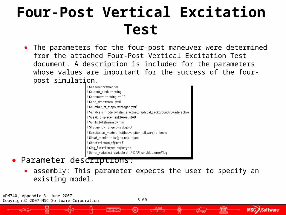
● The parameters for the four-post maneuver were determined from the attached Four-Post Vertical Excitation Test document. A description is included for the parameters whose values are important for the success of the four-post simulation.
● Parameter descriptions:● assembly: This parameter expects the user to specify an existing
model.
B-61ADM740, Appendix B, June 2007Copyright 2007 MSC.Software Corporation
Four-Post Vertical Excitation Test
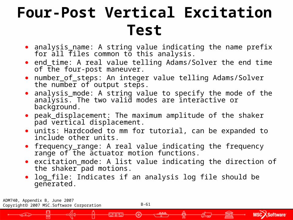
● analysis_name: A string value indicating the name prefix for all files common to this analysis.
● end_time: A real value telling Adams/Solver the end time of the four-post maneuver.
● number_of_steps: An integer value telling Adams/Solver the number of output steps.
● analysis_mode: A string value to specify the mode of the analysis. The two valid modes are interactive or background.
● peak_displacement: The maximum amplitude of the shaker pad vertical displacement.
● units: Hardcoded to mm for tutorial, can be expanded to include other units.
● frequency_range: A real value indicating the frequency range of the actuator motion functions.
● excitation_mode: A list value indicating the direction of the shaker pad motions.
● log_file: Indicates if an analysis log file should be generated.
B-62ADM740, Appendix B, June 2007Copyright 2007 MSC.Software Corporation
Four-Post Vertical Excitation Test
● Error handling● The error handling section of each analysis macro should contain
checks to identify inappropriate assemblies or invalid user-entered values. The error handling section should also contain checks to ensure the assembly contains subsystems that are required to perform a desired maneuver. For example, if you are creating an analysis macro to perform a full-vehicle, straight-line braking maneuver, a check should be performed to ensure that a brake subsystem exists within the assembly. The error handling section should also have checks to ensure that the values specified by the user for specific parameters are realistic.
● The four-post analysis must be performed with the __acme_4PostRig test rig described in the attached case study. The setup of the assembly and test rig, described in a later section, perform actions based on the elements known to exist in the __acme_4PostRig test rig. In addition to verifying that the correct test rig is used, the macro also determines if the analysis name is unique for this assembly.
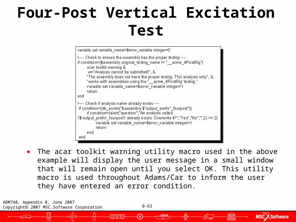
B-63ADM740, Appendix B, June 2007Copyright 2007 MSC.Software Corporation
● The acar toolkit warning utility macro used in the above example will display the user message in a small window that will remain open until you select OK. This utility macro is used throughout Adams/Car to inform the user they have entered an error condition.
Four-Post Vertical Excitation Test
B-64ADM740, Appendix B, June 2007Copyright 2007 MSC.Software Corporation
Four-Post Vertical Excitation Test
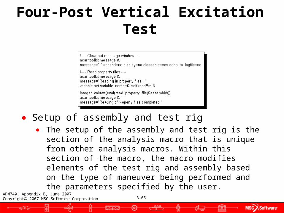
● Reading of property files● Many force elements within Adams/Car get their nonlinear
characteristics from property files. This information must be updated immediately before an analysis is performed. If the property files are not read, the force elements will typically contain inappropriate information that will directly affect the accuracy of the analysis results.
● After validation of the assembly, property file information must be read in and assigned. The following example can be used directly within a user's analysis macro. The $assembly parameter must be an Adams/Car assembly as described above. Property files are read in via a user function as described in the following example. This example also demonstrates how to use the acar toolkit message utility macro to descriptive text to the message window. It is very important that the property files are read before the analysis is submitted to Adams/Solver.
B-65ADM740, Appendix B, June 2007Copyright 2007 MSC.Software Corporation
● Setup of assembly and test rig● The setup of the assembly and test rig is the section of the
analysis macro that is unique from other analysis macros. Within this section of the macro, the macro modifies elements of the test rig and assembly based on the type of maneuver being performed and the parameters specified by the user.
Four-Post Vertical Excitation Test
B-66ADM740, Appendix B, June 2007Copyright 2007 MSC.Software Corporation
Four-Post Vertical Excitation Test
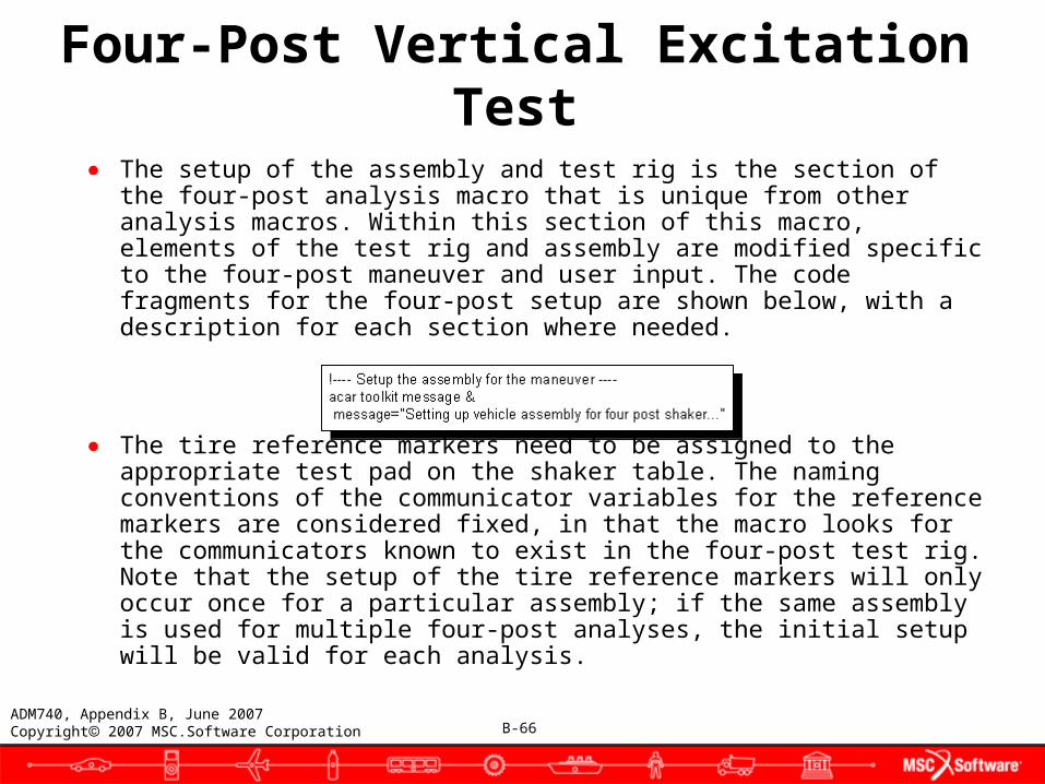
● The setup of the assembly and test rig is the section of the four-post analysis macro that is unique from other analysis macros. Within this section of this macro, elements of the test rig and assembly are modified specific to the four-post maneuver and user input. The code fragments for the four-post setup are shown below, with a description for each section where needed.
● The tire reference markers need to be assigned to the appropriate test pad on the shaker table. The naming conventions of the communicator variables for the reference markers are considered fixed, in that the macro looks for the communicators known to exist in the four-post test rig. Note that the setup of the tire reference markers will only occur once for a particular assembly; if the same assembly is used for multiple four-post analyses, the initial setup will be valid for each analysis.

B-67ADM740, Appendix B, June 2007Copyright 2007 MSC.Software Corporation
Four-Post Vertical Excitation Test
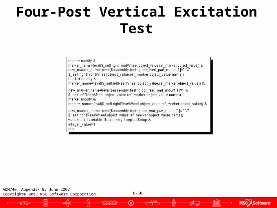
● For each wheel, the tire reference marker is assigned to a shaker pad. The first step is to find each tire in the full-vehicle assembly. The reassignment occurs via an output communicator in the test rig.
For more information on communicators, see the Templates tab in the Adams/Car online help.
● The communicator holds the name of the part on the shaker pad where the tire reference marker should be attached.
B-68ADM740, Appendix B, June 2007Copyright 2007 MSC.Software Corporation
Four-Post Vertical Excitation Test

B-69ADM740, Appendix B, June 2007Copyright 2007 MSC.Software Corporation
Four-Post Vertical Excitation Test
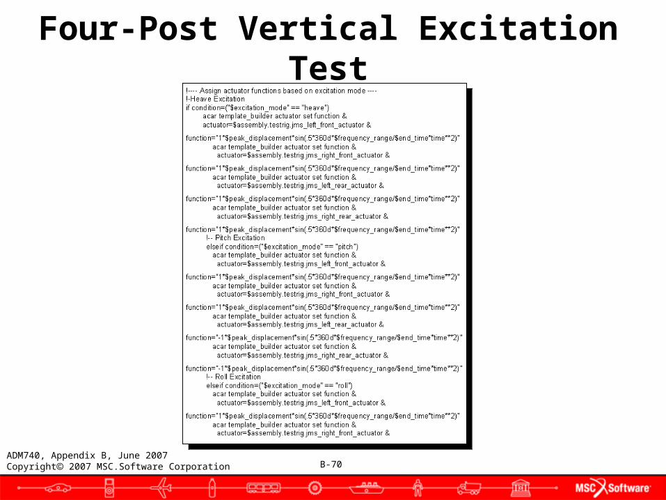
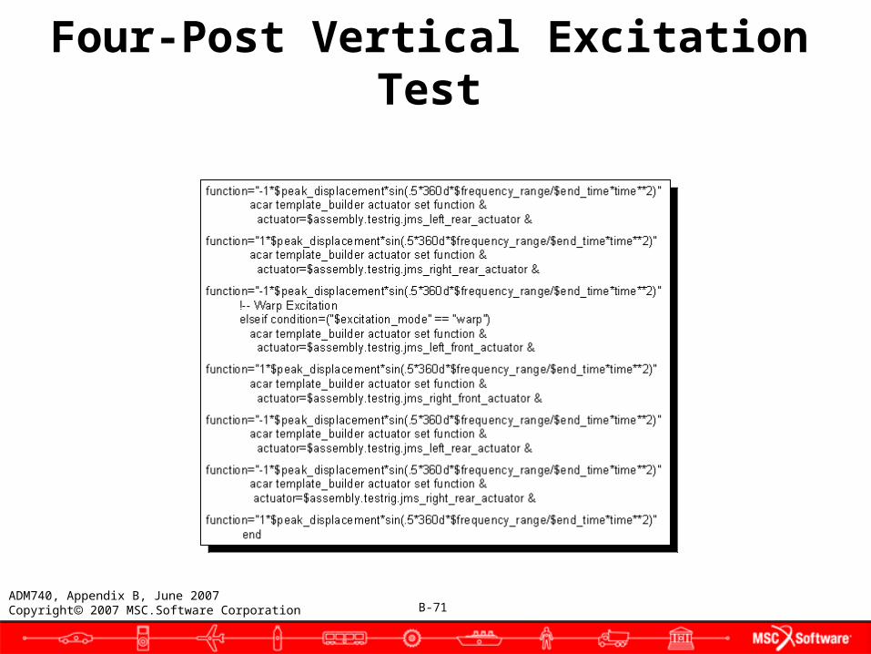
● The motion actuators driving the displacement of the shaker pads must be reset for each individual four-post analysis. This is in contrast to the tire reference marker setup described above, which needs to occur only once for a particular assembly, and remains valid for all successive four-post analyses. The four excitation modes are heave, pitch, roll, and warp. Each of the four shaker pads will have the same magnitude of motion, but a specific excitation mode will determine the direction of the motion. In heave mode, all four shaker pads will move in the same direction. In pitch mode, the front and rear tires will move in opposite directions. For roll mode, the left and right tires have motion in opposite directions. When warp mode is specified, the left front and right rear tires will move opposite to the direction traveled by the right front and left rear tires. The different excitation modes are achieved by specifying a "1" or "-1" multiplier at the beginning of the actuator function definition.
B-70ADM740, Appendix B, June 2007Copyright 2007 MSC.Software Corporation
Four-Post Vertical Excitation Test
B-71ADM740, Appendix B, June 2007Copyright 2007 MSC.Software Corporation
Four-Post Vertical Excitation Test
B-72ADM740, Appendix B, June 2007Copyright 2007 MSC.Software Corporation
Four-Post Vertical Excitation Test
● Submitting the analysis● A common requirement of submitting the analysis to Adams/Solver
is the existence of an MD R2 Adams dataset file (.adm) and an MD R2 Adams command file (.acf). The two basic types of analyses within Adams/Car are suspension and full-vehicle analyses. In both of these cases, a utility macro is used to generate the ADM and ACF files and submit the analysis to Adams/Solver. These utility macros are executed from within each of the suspension or full-vehicle analysis macros.
● After setting up the assembly, it is ready to be submitted for the four-post analysis. Since this is a full-vehicle assembly, the corresponding full-vehicle submission utility macro is used. In this case, two additional parameters are specified to have non-default values for the four-post simulation: generate_road_geometry and simulation_type.

B-73ADM740, Appendix B, June 2007Copyright 2007 MSC.Software Corporation
Four-Post Vertical Excitation Test
● The code fragment for calling the four-post full-vehicle submission macro is shown, with the important associated parameters described next.
● Parameter descriptions:● assembly: This parameter expects the user to specify an existing
model.● analysis_name: A string value indicating the name prefix for all files
common to this analysis.

B-74ADM740, Appendix B, June 2007Copyright 2007 MSC.Software Corporation
Four-Post Vertical Excitation Test
● end_time: A real value telling Adams/Solver the end time of the maneuver.
● number_of_steps: An integer value telling Adams/Solver the number of output steps.
● analysis_mode: A string value to specify the mode of the analysis. The two valid modes are interactive or background.
● load_results: A string value that specifies if the results of the analysis should be read in after the analysis is complete. Expected values are yes or no.
● road_data_file: Hardcoded to BEDPLATE to indicate that the car will not be driven across a road surface. Adams/Car will internally interpret and understand this hardcoded value.
● generate_road_geometry: Set to no to indicate that Adams/Car should not generate a geometric representation of the data found in the road_data_file.
● simulation_type: Hardcoded to fourpost to indicate that the full-vehicle will be attached to a four-post shaker table. Adams/Car will internally interpret and understand this hardcoded value to produce the correct .adm and .acf files.
B-75ADM740, Appendix B, June 2007Copyright 2007 MSC.Software Corporation
Four-Post Vertical Excitation Test
● Logging the analysis● Many users consider it very important to generate a log describing
the analysis that is performed. Generation of the log file is important because it provides historical data that can be stored along with the results of the analysis. The stored data can be useful and is sometimes required to allow a user to regenerate the results of a particular analysis. These utility macros are executed from within each of the suspension or full-vehicle analysis macros.
● Utility macros exist that can be used within your custom analysis macro to generate a log file. A utility macro exists for both suspension and full-vehicle analyses. With the analysis completed, the results may be logged to a file. In addition, final diagnostic messages may be displayed to the message window.

B-76ADM740, Appendix B, June 2007Copyright 2007 MSC.Software Corporation
● Finishing up● Finally, it is important to ensure all local variables created in
the macro using the $_self nomenclature are deleted.
Four-Post Vertical Excitation Test
B-77ADM740, Appendix B, June 2007Copyright 2007 MSC.Software Corporation