azpurua cristina 582759 finaljournal
DESCRIPTION
ÂTRANSCRIPT

1
ARCHITECTURE DESIGN STUDIO: AIRCRISTINA AZPURUA
582759DESIGN JOURNAL

2
3
CONTENT
About me
PART AA.1 Design Futuring A.2 Design Computation A.3 Composition/Generation A.4 ConclusionA.5 Learning Outcomes A.6 Algorithmic sketches
PART BB.1 Research FieldB.2 Case Study 1.0B.3 Case Study 2.0B.4 Technique: developmentB.5 Technique: prototypesB.6: Technique: ProposalB.7: Learning objectives and outcomesB.8 Appendix: Algorithmic sketches
PART CC.1 Design conceptC.2 Tectonic elements C.3 Final design and model C.4 Additional LAGI brief requirenments C.5 Learning outcomes
APPENDIX: algorithmic sketches
References
4
68
1420282930
323440526270828688
9092
104114118120
130
132

4
ABOUT ME
CRISTINA AZPURUA
Originally from Venezuela and moved to Australia about 4 years ago. I am a 3rd year architecture student at The University of Melbourne.
Architecture and design have always been present in my life. Both my parents are civil engineers and had their own company back in Venezuela. Whenever I had to be in the office, I spent my time with the architects of the firm watching what they were doing, and by observing them I developed an interest towards ar-chitecture.
I am lucky to have travelled to various places throughout my life, and witnessed different cities and architectural styles. The first thing that would catch my interest when arriving to a new city would be the architecture surrounding me. It is a great feeling to be able to learn architecture, knowing you have been to many of the places that wrote the history of it, and not just learn from what is being told, but by remembering your previous experiences in differernet places.

5

6

7
PART A

8
Land Art Generator Initiavive (LAGI)
A.1 DESIGN FUTURING
Design brief:
Create a design that must be an en-ergy generator system capable of capturing energy from nature, and transforming it into electricity to later be utilized by the city. Design must be pragmatic but at the same time constructible, and its height must not exceed 125m high. The sculp-ture must estimuate or challenge the mind, be innovative, parametric and original.
About LAGI
The strategic objective of LAGI is ‘to advance to the successful imple-mentation of sustainable design so-lutions by integrating art and interdis-ciplinary creative int the conception of renewable energy infrastructure’1

9
Site description
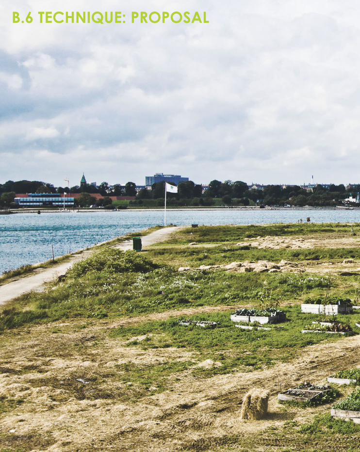
Site is located in Copenhagen, Den-mark. The site consists or a large open area constrained into a rect-angular boundary, surrounded by water on three of its sides, leaving the remaining one connected to the land. Depending on where the viewer is standing, one can feel to be either in an open area, or a se-cluded enclosed one; depending if the viewer is looking to the water with the city in the background, or into the mainland surrounded by di-verse edifications.
[1]
(1) Google Maps Aerial view of Refshaleøen, Copenhagen, Denmark https://maps.google.com.au/

10
PREVIOUS COMPETITION ENTRYWATER CIRCLE + LAND PATCH2
I find this design interesting because it pushes the boundaries. it does not restrict itself to the use of the given site, but reaches out into the water.
The design shows a close relationship between the landscape and the human body. It emphasizes on the human experience, but achieves it without resorting to conventional systems. Nature is present not only in the context, but also in the inspira-tion of the design.
The design consists of two ma-jor features, the water ‘cir-cle’ and the land ‘patch’.
Circle consists of a rotating wa-ter wheel that harnesses energy through motion. People get to walk on the rotating platform, which could be interpreted as visitors are experiencing the motion of energy harnessing. A strong sense of inter-atction is present, which makes the visitors engage with the design. An interesting fact is that eye level is at the level of the surface, creating the idea that bodies are being sum-erged in the water, but bodies stay dry. This is an interesting idea and way to approach the design. The rotating wheel is in constant motion, therefore, if visitors are on it, they would have to experience and wait for the wheel to reach a new posi-tion before they can make their way out the bridge.
Patch is located on the site. It is de-signed as well for human interaction and experience. Same as circle, it is constantly in motion, with the pres-ence of wind. Even though it is an artificial creation, it could be con-sidered to be an extension of the natural landscape as it ‘reconciles people to beautiful forms of nature’
[2]
[3]
Aerial view of ‘patch’
Aerial view of ‘circle’
(2) http://landartgenerator.org/LAGI-2012/WH181390/(3) http://landartgenerator.org/LAGI-2012/WH181390/

11
Design as a energy generator.
Both ‘circle’ and ‘patch’ caputure multiple renewable energy sources, crucial to adapt to daily dynamics of weather and climate. Energy is being taken by different ways and natural elements, such as:
1. solar energy that is dominant dur-ing the daylight. 2. winds that are stronger during dawn and late afternoon.3. water currents that are mostly sta-ble during the day.
It is interesting how it uses all the natural resources present in site to generate energy. Designers under-stand that not only one element could generate all the energy be-cause the weather conditions and climate vary during the days. they benefit from the dominant element present in the day. It strogly supports the idea that it is using the natural resources to their limit. the differnt renewable energy sources provide the required adaptability to differ-ent conditions.
Structure formed of mesh structure composed of lightweight thin film so-lar cells, ETFE sheets and fiber glass.
[4]
[5]
(4) http://landartgenerator.org/LAGI-2012/WH181390/(5) http://landartgenerator.org/LAGI-2012/WH181390/
section of ‘circle’, how ground level changes in the floating platform.
Perspective view of ‘circle’ in the fore-ground and ‘patch’ in the background

12
ENERGY GENERATORS HYDROELECTRYCITY-USING WATER TO CREATE ENERGYDAMMED RESERVOIR3
Generates approximately 20% of world’s electrical energy. I chose this method of energy generation because it uses the biggest natural resource. The water is already pres-ent to generate the energy. It is the most established form of renew-able energy; and accounts more than 80% of all renewable energy installed capacity.
It uses dam structures to limit the flow of exisiting rivers. It functions by selectively releasing water through turbines in the dam, the water pres-sure is then converted into electrical energy.
Although it is using the water to gen-erate energy, fauna and habitat in the water is being affected by the dam. It is successful but at the same time, if not thoguht through or well designed, could be very destructive to the natural elements in it. Dam could also experience a struc-tural failure, and whole structure could collapse.
[6]dammed reservoir
[6] http://landartgenerator.org/LAGI-FieldGuideRenewableEnergy-ed1.pdf

13
WIND GENERATED ENERGYHORIZONTAL AXIS WIND TURBINE (HAWT)4
The standing out feature of this en-ergy generator is the use of two dif-ferent elemenst; wind and water. It takes energy from the ocean, ad-vantaging from its large open area. In the middle of the ocean, wind currents are stronger than those found in land, which means it was designed to benefit from the best conditions possible.
[7] http://landartgenerator.org/LAGI-FieldGuideRenewableEnergy-ed1.pdf
two types of these turbines can be found. the first refers to turbines mounted on pylons in shallow wa-ters, and the second refers to tur-bines floating in deep waters. float-ing turbines have the ability to move and adjust towards winds currents in order to be able to collect as much wind as possible to create more en-ergy.
It must be taken into consideration what these turbines could do and how would they affect the econsys-tems surrounding them.
[7]horizontal axis wind turbine
14
A.2 DESIGN COMPUTATION
‘computation is redifining the practice of architecture’
AD Journals, Volume 83, Issue 2, p.10

15
Computation is making architects and designers become dependant to computer softwares to a certain extent. Computation allows the cre-ation of a design to be fully created with computer software; architects do not have a set idea of that the final project will look like until is gen-erated. It is affecting the design pro-cess in a way that designers do not need to have a set idea of the finish product when designing, because it is subject to change. This does not mean computation makes design processes easier, but it is a different approach to them.5
Computation allows the transfor-mation of abstract technologies into buildable concrete projects, it is up to designers to reach that point where the abstract idea and form becomes buildable; however, it does not have to be coherent or with a regular shape.
In computation, the computer is not used to generate a structure, but a process; meaning there is no limit in what can be added or applied. Computation is usually faster to gen-erate designs and solve problems, compared to traditional ways to ap-proach design processes.

16
Khan Shatyr Entertainment Centre,Astana, Kazakhstan, 2010, Foster + Partners,6
Design was created by using a ‘form finding Algorithm’, which allowed the design team to generate quick-ly design options for the cable-net structure.
The computational building consists of a giant transparent tent. It is 150m high, and a 200m eliptical base cov-ering 140 000m^2. Underneath the tent, a large covered area takes place; big enough to hold 10 foot-ball stadiums, where one can find a shopping center, mini golf and in-door beach resort, amongst others.
The transparency of the building al-lows natural light through it, optimiz-ing the climate conditions on the inside.
The building was created using a computer software. The design was created by experimenting with computer programs and chang-ing the values of the algorithm and components, in order to reach the desired shape, form and structure. Designers did not have a set idea of what they wanted to design, com-puter experimentation provided the freedom to try and experiemnt with different values until a desired formed derived.
A.2 PRECEDENT 1
[8]algorithmic sketches of the design
[8] AD Journals, Volume 83, Issue 2, p.9 http://onlinelibrary.wiley.com.ezp.lib.unimelb.edu.au/doi/10.1002/ad.1545/pdf

17
[9]perspective photo showing transparency of structure
[10]Photo taken during the night showing iluminated structure
[9] AD Journals, Volume 83, Issue 2, p.10http://onlinelibrary.wiley.com.ezp.lib.unimelb.edu.au/doi/10.1002/ad.1545/pdf[10] AD Journals, Volume 83, Issue 2, p.10http://onlinelibrary.wiley.com.ezp.lib.unimelb.edu.au/doi/10.1002/ad.1545/pdf
Understanding the concept of com-putation, one can understand that this is not a computation design, but a computerisation one. Designers could have intended to to a cone shape structure, but used the com-puter to further develop from such basic idea. However, the cablenet structure can be argued to be a computation design.
18
A.2 PRECEDENT 2
located in Central Seville, Metropol Parasol provides the city with new amenities such as museum, market space and viewing platform. it revit-alised a historic square, in a historic city, it provided the city with a mod-ern element, that although different, pictouresque.
Previously, the plaza where Metropol Parasol was located, was used as a car park. The communitiy decided that the city needed that space to create something else, so excava-tions started. with the excavations, they found a roman archeological site and had to stop the project. A competition took place to design something to reavitilize the square, and the Metropol Parasol design was triumphant in the competi-tion. It provides the city of Seville a different look, contrasting to its sur-roundings, controversial many might say, but engaging; it had nothing in common with the architecture of the city.
Metropol Parasol, Seville, Spain, Jurgen Mayer, Herman7
There is a clear interaction between design and users. Users get not only to walk underneath it and appreci-ate from below, but also get to walk above it thorugh the walk paths and experience it from above, as well as the city surrounding it. Users can also expereience the contrast of the design and the city, and make their own opininons about it.
It is a computational design that was created completely using co-puter softwares. Designers could have an abstract idea of what they wanted to achieve, but the com-puter finalised and gave a concrete form to the design. Designers had to go through a lot of experimentation in order to reach the intended and final design.
Many would argue this is an unprac-tical structure, expensive and point-less. Such simple form should not be taken into such large scale; it is ex-pensive and problematic to build.
[11] AD Journals, Volume 82, Issue 5, p.70http://onlinelibrary.wiley.com.ezp.lib.unimelb.edu.au/doi/10.1002/ad.1463/pdf[12] AD Journals, Volume 82, Issue 5, p.73http://onlinelibrary.wiley.com.ezp.lib.unimelb.edu.au/doi/10.1002/ad.1463/pdf

19
[11]aerial view of design
[12]view from below of the structure

20
A.3 COMPOSITION/GENERATION
‘Computational design pro-vides a technical means to develop new structural forms’.
‘The introduction of compu-tational design offers the po-tential to break through these barriers of model thinking in structural engineering’.
AD Journals, Volume 83, Issue 2, p.77
AD Journals, Volume 83, Issue 2, p.77

21
Most architects have been using the computer softwares to further de-velop their ideas of design, and to present them in a more clear way, referring to this as ‘computarisation’; computation challenges this notion of a set idea, it encourages design-ers to fully develop their design ideas and processes by using the comput-er, and create a not expected out-come from it.
Computation is defined as ‘the pro-cessing of information between el-ements which constitute a specific environent...with the capacity to generate complex order, form and structure8
In computation, the design process becomes part of the design itself; computation can also be fully inte-grated into the practice and the ac-tual design process. With this in mind, there is no difference between the design intent and computational technique, they both become part of one and another.9
An algorithm is a particular set of in-structions, and for these to be under-stood by the computer, they must be written in a language it understands, a code. Computational designers generate and modify ideas through algorithms. An algorithmic thought is the accumulation of ideas derived from tools and codes.
22
A.3 PRECEDENT 1Westfield London shopping centre, White City, London, 2008, Benoy and Knippers Helbig Ad-vanced Engineering10
The structure of the roof is a compu-tational design. It is made of thou-sands of plates of different geom-etry and different thicknesses; each one specific to a different type of load at a specific point. The creativity of the engineering and design is not in the construction of the physical structure, but into the parmetric generation and control of data.
For this specific design, a planar grid was mapped on the 3D surface.
The physica appearance of the design appears to be incomplete and fragmented; however, this is a design intent of the structure. figure [13] shows a photo taken on the in-side of the building. It shows that the roof structure appears incomplete, where the grid panel is the domi-nant feature. However, it could be argueed that the covered areas are to provide shading to the inside, and the open geometric shapes are present to allow natural light, serving as skylights.
Special care and consideration was put into the finished outcome, con-sidering where shaded was needed and where natural light should be allowed inside.
The design is interesting to look at, and provides a different look to what previous shopping centres look like.
[13] AD Journals, Volume 83, Issue 2, p.78http://onlinelibrary.wiley.com.ezp.lib.unimelb.edu.au/doi/10.1002/ad.v83.2/issuetoc[14] http://www.overseaspropertymall.com/wp-content/uploads/2008/10/westfield-shopping-centre-white-city-shepards-bush-london.jpg

23
[13]view of the roof from the inside during day time
[14]view of the roof from the inside during night time

24
A.3 PRECEDENT 2Architecture’s thematic Pavilion at Yeosu World Exposition, South Korea, 201211
The building consists of a computa-tional design with a kinetic fcade of fins which move in ocean-like pat-terns.
The project has 114 louvres that vary from 3 to 14 metres in length; made out of glass-fibre reinforced polymers, 8mm thick. Compression forces are applied both at the top and bottom to generate the move-ment, generating elastic deforma-tion. Engineers usually tend to avoid this type of deformation, but the close calculation and attention to detail made this interesting design possible.
Advanced computational mechan-ics were used to create this design, rather than 3D modelling or simple digital fabrication.
The structure serves as a tourist des-tination, as well as a permanent at-traction for residents. The design is welcoing and mysterious; vieweres are invited to understand and find out what the structure does, and what it has to offer.
The building is in constant move-ment; it is engaging and visitors do not know what to expect from it. It is an exhibition centre, but not only on the interior, the exterior is worthy to be admired by many.
Careful detail and thought had to be put into the design, because it is not only a static design. Design-ers had a lot of things to consider when designing it, but it was easier for them to rely on computer soft-wares that facilitatd the solution to any problem they might have had.
[15]http://www.designboom.com/architecture/soma-one-ocean-thematic-pavilion-for-yeosu-expo-2012-complete/[16]http://www.designboom.com/architecture/soma-one-ocean-thematic-pavilion-for-yeosu-expo-2012-complete/[17]http://www.designboom.com/architecture/soma-one-ocean-thematic-pavilion-for-yeosu-expo-2012-complete/

25
[15]longitudinal view of the design
[17]close up of the louvres that vary in size looking wave-like
close-up of opening detail[16]

26
A.3 PRECEDENT 3SBA International’s Expo at Shanghai World Expo,Shanghai, China, 201012
The design consists of a glass cone, with measurments of up to 45metres high; their diameter at the foot is ap-prox. 16 metres, and 80 metres on the upper edge.
It is present on this design the idea of grid generation. Large mega-tri-angles were mapped onto the dif-ferent glass cones. These triangles were subdivided into smaller trian-gles with the same geometry, with vertices connecting six members.
figure [18] shows the different stag-es the design had to go through before reaching its final form. first, the abstract shape created on the computer, then the mega triangle grid working as a decomposition of the original form; and at the end the various smaller triangles making the final form of the structure.
[18]digital process stages of the design
[18] AD Journals, Volume 83, Issue 2, p.78http://onlinelibrary.wiley.com.ezp.lib.unimelb.edu.au/doi/10.1002/ad.v83.2/issuetoc[19] AD Journals, Volume 83, Issue 2, p.78http://onlinelibrary.wiley.com.ezp.lib.unimelb.edu.au/doi/10.1002/ad.v83.2/issuetoc[20] http://www.superstock.com/stock-photos-images/1801-50112

27
[18]digital process stages of the design
digital process stages of the design digital process stages of the design [19] [20]

28
A.4 CONCLUSION
In the present day, computation is not only effective, but necessary in the production of the largest build-ings today.
It is arguable that computation is a design process that is taking over the design industry; many designers nowadays rely on computation to generate their ideas.
I have gained a vast amount of knowledge by exploring the differ-ent precedents, as well as new con-cepts. Before I started the semester, I did not know the difference be-tween computarisation and compu-tation; but now I understand there is a clear difference. It does not mean that one is easier than the other, it means that they are different ways to approaching the design process.
It is fascinating to see how most of the studied precedents use nature as influence. For instance, ‘water circle and land patch’ or the the-matic pavilion in South Korea. This is an idea I would like to develop and include in my future designs. I be-lieve it fits in the brief, and it is some-thing I am looking forward to further develop.

29
A.5 LEARNING OUTCOMES
Before the semester started, my knowledge about computation, both in theory and practice was not abundant. I have gained knowl-edge through many ways; lectures, tutorials, personal research and ex-plorations.
It is clear now what computation refers to; not the form, but the pro-cess behind. It is a concept that I struggled to get around to becasue it is different to the way I have ap-proached the design processes pre-viuosly.
I have learnt by looking at other proj-ects how computation and digital design can be achieved, and this is a knowledge I’m going to need for the rest of the semester when I have to put my knowledge into practice.
My understanding of the comput-er programs was not the best. But I have learnt new ideas and process-es I can include in my future designs. I have tried not to just learn the grass-hopper commands, but the theory behind it and how the designs are being generated. I believe it will be useful in the future, when I need to rely on my knowledge.
It was difficult to start, I had to change my mindset; but I believe I have learnt useful things that I will not only need in this subject, but in my future career.

30
A.6 ALGORITHMIC SKETCHES
As a result from the online tutorials provided, and personal experimen-tation, I have managed to create interesting designs and shapes using Rhino and the plugin Grasshopper. I have intended to not restrain myself with the given tutorials, but go be-yond and experiment with the soft-ware to create these results.
I have experiemented with several commands; but the most important thing is that I have tried to do every-thing on Grasshopper without rely-ing on Rhino.
I still have a lot to learn, but for the time being, I’m getting to know the program and how it works, rather than just learning the commands so I can use my knowledge in the fu-ture.
31

32

33
PART B
34
B.1 RESEARCH FIELD
BIOMIMICRY
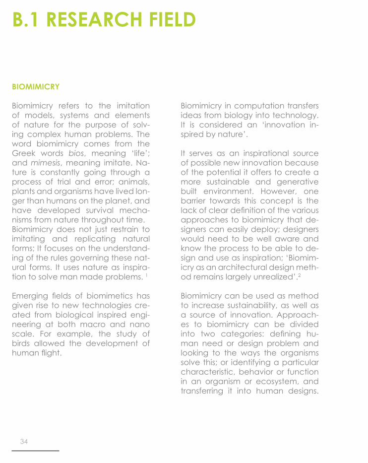
Biomimicry refers to the imitation of models, systems and elements of nature for the purpose of solv-ing complex human problems. The word biomimicry comes from the Greek words bios, meaning ‘life’; and mimesis, meaning imitate. Na-ture is constantly going through a process of trial and error; animals, plants and organisms have lived lon-ger than humans on the planet, and have developed survival mecha-nisms from nature throughout time. Biomimicry does not just restrain to imitating and replicating natural forms; It focuses on the understand-ing of the rules governing these nat-ural forms. It uses nature as inspira-tion to solve man made problems. 1
Emerging fields of biomimetics has given rise to new technologies cre-ated from biological inspired engi-neering at both macro and nano scale. For example, the study of birds allowed the development of human flight.
Biomimicry in computation transfers ideas from biology into technology. It is considered an ‘innovation in-spired by nature’.
It serves as an inspirational source of possible new innovation because of the potential it offers to create a more sustainable and generative built environment. However, one barrier towards this concept is the lack of clear definition of the various approaches to biomimicry that de-signers can easily deploy; designers would need to be well aware and know the process to be able to de-sign and use as inspiration; ‘Biomim-icry as an architectural design meth-od remains largely unrealized’.2
Biomimicry can be used as method to increase sustainability, as well as a source of innovation. Approach-es to biomimicry can be divided into two categories: defining hu-man need or design problem and looking to the ways the organisms solve this; or identifying a particular characteristic, behavior or function in an organism or ecosystem, and transferring it into human designs.

35
DaimlerCrysler bionic car inspired by the box fish and tree growth patterns.
[21]
The Bionic Car illustrates the point. It is more efficient in terms of fuel use because the body is moreaerodynamic due to the mimicking of the box fish. It is also more materi-als efficient due to the mimicking oftree growth patterns to identify the minimum amount of material need in the structure of the car.
The car itself is however not a new approach to transport. Instead, small improvements have been made to existingtechnology without a re-examina-tion of the idea of the car itself as an answer to personal transport.

36
B.1 PRECEDENT 1 The ICD/ITKE Research PavilionStuttgart, 2011
‘The ICD/ITKE Research Pavilion is a chance to explore architecture through computational design’3
In November 2012 the Institute for Computational Design (ICD) and the Institute of Building Structures and Structural Design (ITKE) at the University of Stuttgart have complet-ed a research pavilion that is entirely robotically fabricated from carbon and glass fibre composites.
This interdisciplinary project, con-ducted by architectural and engi-neering researchers of both institutes together with students of the faculty and in collaboration with biologists of the University of Tübingen, inves-tigates the possible interrelation be-tween biomimetic design strategies and novel processes of robotic pro-duction.
The research focused on the ma-terial and morphological principles of arthropods’ exoskeletons as a source of exploration for a new composite construction paradigm in architecture; it explored the sea
[22]
[23]

37
[24]

38
B.1 PRECEDENT 2
The Shadow Pavilion University of Michigan Matthaei Botanical Gardens, Ann Ar-bor, Michigan, USA, 2009Architects: PLY Architecture
The Shadow Pavilion is a structure that, as a result of the removal of material, the structure becomes lighter and weaker.4
The structure is made entirely of holes. It consists of the connection of around 100 aluminium cones that vary in size, and are located next to each other to create a pattern. The cones will allow light to funnel into the internal space of the pavilion.
The design strategy is based on Phyl-lotaxis, ‘the pattern which forms on many flowers and cacti as succes-sive layers of petals, leaves or nod-ules grow to form a spiral.
[25]

39
[27]
[26]
[28]

40
B.2 CASE STUDY 1.0
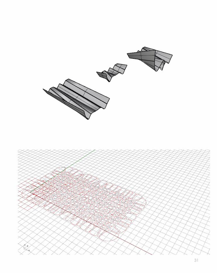
VoltaDom, by Skylar Tibbits - is an in-stallation that populates the corridor spanning building 56 & 66 on MIT’s campus. 5
This installation lines the concrete and glass hallway with hundreds of vaults, reminiscent of the great vaulted ceilings of historic cathe-drals. The vaults provide a thickened surface articulation and a spectrum of oculi that penetrate the hallway and surrounding area with views and light. VoltaDom attempts to ex-pand the notion of the architectural “surface panel,” by intensifying the depth of a doubly-curved vaulted surface, while maintaining relative ease in assembly and fabrication. This is made possible by transforming complex curved vaults to develop-able strips, one that likens the as-sembly to that of simply rolling a strip of material.
It was comissioned for MIT’s 150th Anniversary Celebration & FAST Arts Festival (Festival of Arts, Science and Technology) -
VoltaDom, 2007, Massachusetts Institute of technology

41
[29]

42
POINT
P=5 P=10 P=15
S=0 S=5 S=10
R=0.10 R=0.5 R=0.75
SEED
RADIUS
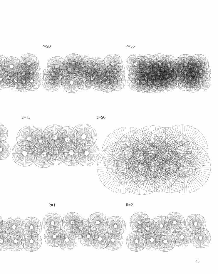
B.2 CASE STUDY 1.0MATRIX
43
P=20 P=35
S=15 S=20
R=1 R=2

44
H=0.5 H=0.8 H=1.5
P=15.0S=8.00R=0.75H=0.80
HEIGHT RATIO
MIXTURE
P=15S=8.0R=0.5H=1.5
B.2 CASE STUDY 1.0MATRIX

45
H=3 H=7
P=27.0S=8.00R=0.65H=8.29
P=14.0S=13.0R=0.28H=9.69
P=35.0S=2.00R=0.25H=8.00

46
Pop2D - different base curves
Pop3D - different base curves
B.2 CASE STUDY 1.0MATRIX

47

48
FalseFalseTrueTrue
TrueTrue
FalseFalse
FalseFalseTrueTrue
FalseFalseTrueTrue
Cone with cull base & height
Cylinder cull base & cone cull height
CULLING PATTERN
B.2 CASE STUDY 1.0MATRIX

49
TrueFalseTrueFalse
FalseTrueFalseTrue
FalseTrue
FalseTrueFalseTrue
Sphere cull base & cone cull height
Cone with cull but with 2nd cone negative height

50
B.2 CASE STUDY 1.0SELECTED FOUR
This iteration is a combination of dif-ferent changes to the given grass-hopper definiton. What I find the most interesting about this iteration is how different it looks to the built design, and that such changes can be achieved by just changing the dimensions on the sliders. Here one can see an increased height on the cylinders, with a smaller radius on the base, making the cylinders look tall and thin.
After experimenting with different 2D bases, I decided to push further and see what would happen if the base was a 3 dimensional curve. The result was interesting as the cylinders would follow the curve all the way through its length. However, I do not think this would be aplicable to future design experimentations be-cause the LAGI site is flat. In order to push this iteration further, I would have to find a way to connect the floating components.
ITERATION 1
ITERATION 3
51
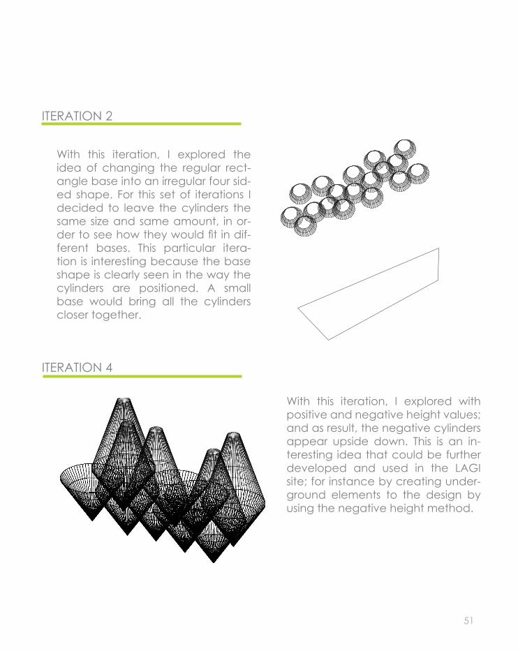
With this iteration, I explored the idea of changing the regular rect-angle base into an irregular four sid-ed shape. For this set of iterations I decided to leave the cylinders the same size and same amount, in or-der to see how they would fit in dif-ferent bases. This particular itera-tion is interesting because the base shape is clearly seen in the way the cylinders are positioned. A small base would bring all the cylinders closer together.
With this iteration, I explored with positive and negative height values; and as result, the negative cylinders appear upside down. This is an in-teresting idea that could be further developed and used in the LAGI site; for instance by creating under-ground elements to the design by using the negative height method.
ITERATION 2
ITERATION 4

52
TIMES EUREKA PAVILION, LONDON, 2011Nex Architecture / Alan Dempsey, Paul Loh, Michal Piasecki, Tomasz Starczewski, James Chung
The design brief for the pavilion was to demostrate commitment to sci-ence and reflect the focus of The Times monthly magazine, Eureka. Not only the pavilion was to be de-signed, but also the garden.6
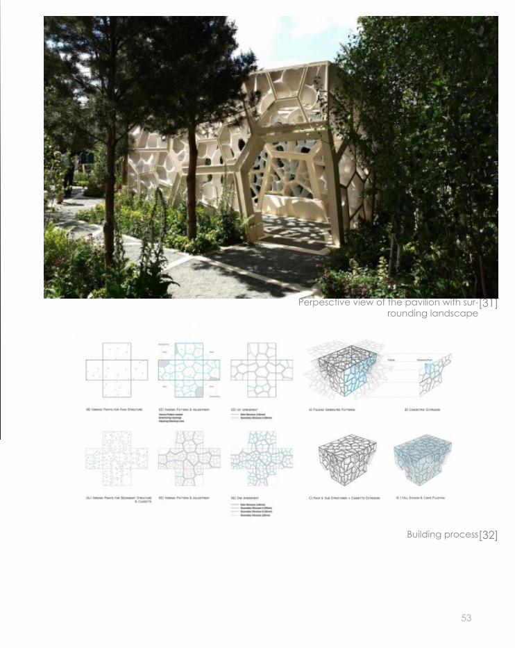
“We extended the design concepts of the garden by looking closely at the cellular structure of plants and their processes of growth to inform the design’s development. The final structure was designed using com-puter algorithms that mimic natu-ral growth and is intended to allow visitors to experience the patterns of biological structure at an unfamiliar scale. The primary structure is timber sourced from sustainable spruce for-ests with a glass panelled roof.”NEX Principal Alan Dempsey.
The design development of the pa-vilion focused on the ‘bio-mimicry’ of leaf capillaries being embedded in the walls. The structural geometry was finalised to use primary timber capillaries (300dp x 140wd) to form the basic shape and supporting structure of the pavilion, inset with secondary timber cassettes that hold the cladding. Following com-pletion of the 3D modelling to meet architectural and structural needs, specialist timber fabricators under-took detailed analysis and digital manufacturing of the structure.
This is an interesting design that does not just focus in aesthetics, but also in functionality. This is seen by the way it is designed to collect water through the capillary structure of the leaves. It is a way to connect us with nature, by creating a large scale structure of something that is surrounding us, but we never see. This idea could be used in our de-sign proposal by raising awareness of the environment and surrounding elements.
B.3 CASE STUDY 2.0
Perspective render of the pavilion [30]
53
Perpesctive view of the pavilion with sur-rounding landscape
[31]
Building process[32]
54
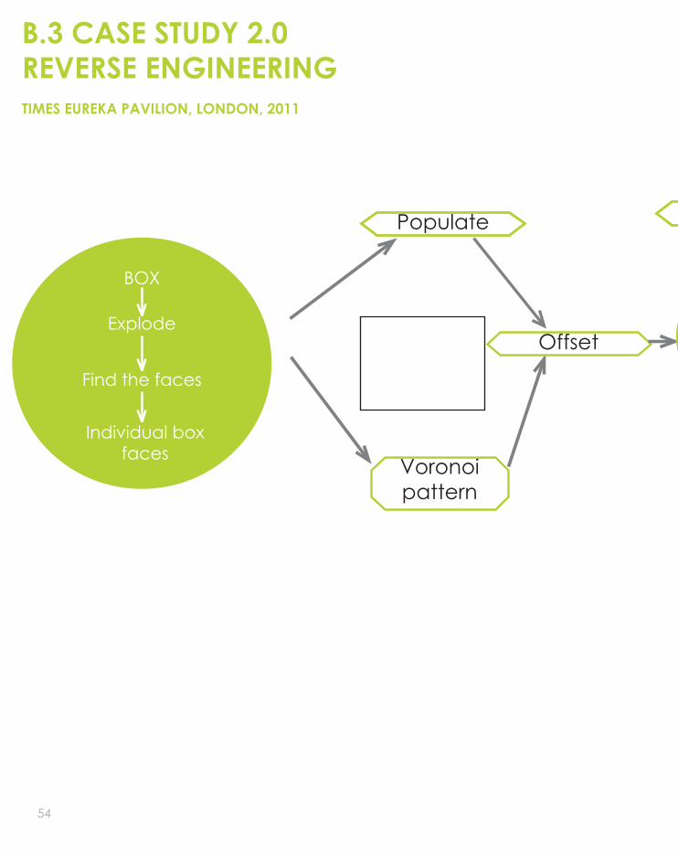
B.3 CASE STUDY 2.0REVERSE ENGINEERING
BOX
Explode
Find the faces
Individual box faces
Populate
Voronoi pattern
Offset
Structure
TIMES EUREKA PAVILION, LONDON, 2011

55
Loft
Structure
Extrude Offset
Boundary surface
Intersect voronoi
Voronoi curves Boundary surface
Extrude
56
TIMES EUREKA PAVILION, LONDON, 2011
B.3 CASE STUDY 2.0REVERSE ENGINEERING
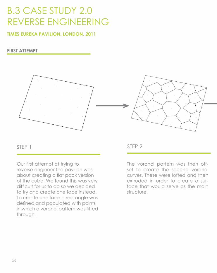
STEP 1 STEP 2
Our first attempt at trying toreverse engineer the pavilion wasabout creating a flat pack versionof the cube. We found this was verydifficult for us to do so we decidedto try and create one face instead.To create one face a rectangle wasdefined and populated with pointsin which a voronoi pattern was fittedthrough.
The voronoi pattern was then off-set to create the second voronoi curves. These were lofted and then extruded in order to create a sur-face that would serve as the main structure.
FIRST ATTEMPT

57
STEP 3 STEP 4
Similar to step 2, the curves were off-setted again but to a different dis-tance and with this we created the details for the main structure.
The mid-points if the initial offset vo-ronoi curves were found in order to be able to create the secondary structure of the pavilion. This was achieved by using another voronoi, and it was extruded afterwards. In order to create the voronoi pattern inside the previous cells, the differ-ence between the two surfaces needed to be found. Afterwards, the other faces of the structure were created using the same process, but when put together the outcome was not succesful; which is when we decided to follow a new approach to reverse engineer the design.

58
TIMES EUREKA PAVILION, LONDON, 2011
B.3 CASE STUDY 2.0REVERSE ENGINEERING
STEP 1 STEP 2
SECOND ATTEMPT
Instead of doing each surface sep-arately and then put together as previously done, we decided to construct a cube as the base. The cube was then exploded so each face could be treated differently because they are located in differ-ent planes, and require different set-tings. The faces were then individu-ally populated with points. A voronoi was placed in each face to create the pattern, same as previously done.
A voronoi was then offset on each face. Each face was treated indi-vidually in order to find the normal to ensure that all the faces could offset in the same direction around the cube.

59
STEP 3 STEP 4
Same as previously done in our first attempt on steps 3 and 4, a voronoi was located in each cell on each individual face; again this was done separately for each face, where they were evaluated in order to find the normal and ensure that the off-set and the extrude were done in the right direction.
The image above shows how the structure was created. It does not show the voronois inside each indi-vidual cell so that the structure could be appreciated and understood.

60
TIMES EUREKA PAVILION, LONDON, 2011
B.3 CASE STUDY 2.0REVERSE ENGINEERING

61
This is the finished outcome of our reverse engineering. I believe it is successful because it resembles the original design. We were able to construct something similar to the final outcome.
It is similar in the way that two different voronoi patterns can be found; one as the structure, and another one in each individual cell of the structural one. However, the original one uses a specific number of points and are carefully located and calculated in order that the cells join on the edges as a continuous shape, rather than be-ing cut at the edges of each different face of our reversed engineered design. Also, the original design has openings, whereas our reversed engineered design is an enclosed cube with the pattern on each face.
Moving to our own design, we intend to focus not on the shape of the pavilion, but on the way the voronois are being used, and how we could develop and move for-ward from it. We also intend to introduce site specific in-formation and data such as yearly wind averages and this would be achieved by using the kangaroo plugin into our grasshopper definition.

62
B.4 TECHNIQUE: DEVELOPMENT MATRIX 1
diagrid hexagonal
RC sizeOffset 01Offset 02
RC sizeOffset 01Offset 02
RC sizeOffset 01Offset 02
U valueV valueOffset
U value
V valueOffset
RC sizeOffset 01Offset 02
Points
Offset 01Offset 02
Points
Offset 01Offset 02
Points
Offset 01Offset 02
RECTANGLE SIZE
STRUCTURE CHANGE
MAP TO SURFACE

63
braced grid hexagonal 2
RC sizeOffset 01Offset 02
RC sizeOffset 01Offset 02
RC sizeOffset 01Offset 02
RC sizeOffset 01Offset 02
U value
V valueOffset
U value
V valueOffset
Points
Offset 01Offset 02
Points
Offset 01Offset 02
Points
Offset 01Offset 02

64
B.4 TECHNIQUE: DEVELOPMENT MATRIX 2
+X
+Y+z
Speed
+X
-Y+z
Speed
+X
-Y+z
Speed
+X
-Y+z
Speed
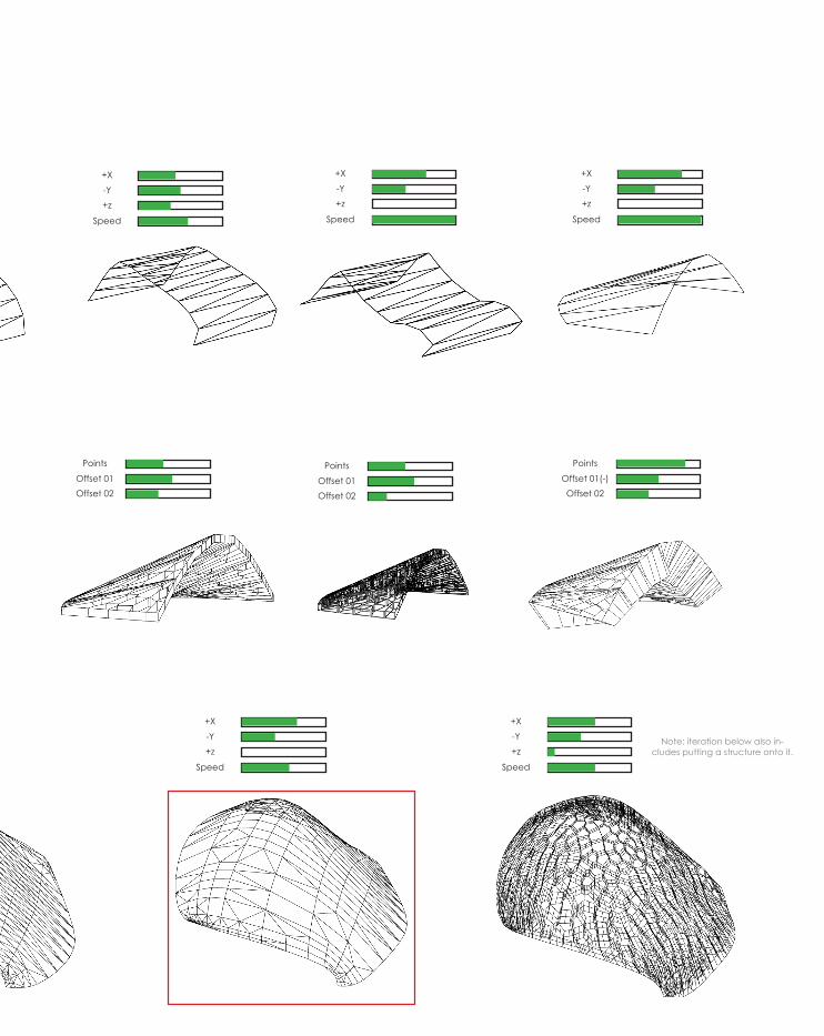
FORM FINDING WIND DIRECTION
Points
Offset 01Offset 02
Points
Offset 01Offset 02
Points
Offset 01Offset 02
MAP TO SURFACE 2
FORM FINDING WIND DIRECTION +X
+Y+z
Speed
+X
-Y+z
Speed
+X
-Y+z
Speed
65
+X
-Y+z
Speed
+X
-Y+z
Speed
+X
-Y+z
Speed
Points
Offset 01Offset 02
Points
Offset 01Offset 02
Points
Offset 01(-)Offset 02
+X
-Y+z
Speed
+X
-Y+z
Speed
Note: iteration below also in-cludes putting a structure onto it.
66
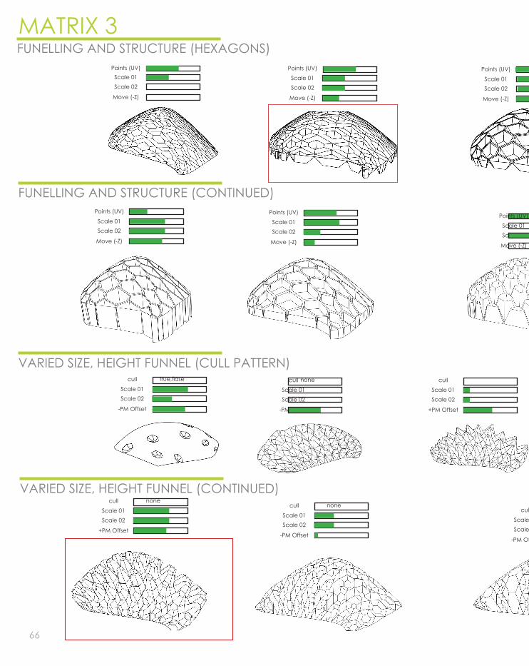
MATRIX 3FUNELLING AND STRUCTURE (HEXAGONS)
Points (UV)Scale 01Scale 02
Move (-Z)
Points (UV)
Scale 01Scale 02
Move (-Z)
Points (UV)
Scale 01Scale 02
Move (-Z)
Points (UV)
Scale 01Scale 02
Move (-Z)
Points (UV)
Scale 01Scale 02
Move (-Z)
Points (UV)
Scale 01Scale 02
Move (-Z)
FUNELLING AND STRUCTURE (CONTINUED)
VARIED SIZE, HEIGHT FUNNEL (CULL PATTERN)cull
Scale 01Scale 02
-PM Offset
true,flase cull
Scale 01Scale 02
-PM Offset
none cull
Scale 01Scale 02
+PM Offset
VARIED SIZE, HEIGHT FUNNEL (CONTINUED)cull
Scale 01Scale 02
+PM Offset
nonecull
Scale 01Scale 02
-PM Offset
nonecull
Scale 01Scale 02
-PM Offset

67
Points (UV)
Scale 01Scale 02
Move (-Z)
Points (UV)
Scale 01Scale 02
Move (+Z)
Points (UV)
Scale 01Scale 02
Move (-Z)
Points (UV)
Scale 01Scale 02
Move (-Z)
Points (UV)
Scale 01Scale 02
Move (-Z) Note: Different loft option used not much variation.
Points (UV)
Scale 01Scale 02
Move (+Z)Move (-Z)
cull
Scale 01Scale 02
-PM Offset
none
cull
Scale 01Scale 02
-PM Offset
true,flase,falsecull
Scale 01Scale 02
-PM Offset
none

68
B.4 TECHNIQUE: DEVELOPMENTSELECTED FIVE
We thought this iteration could be use-ful for us when thinking about what type of energy generator to use on our de-sign. We want to develop the idea of joining design with energy generator, rather than having one thing on top of each other. The panels could be clad with piezoelectric material allowing mechanical pressure from wind to be captured and converted into electrical current. The panels could be oriented facing the direction where the wind currents are the strongest and with that generate the maximum amount of en-ergy possible from the wind.
ITERATION 1
ITERATION 2
We could see a resemblance between this iteration and The Shadow Pavilion discussed earlier. The pavilion uses the openings to channel light and sounds to influence the user’s experience. We believe this iteration could provide the same use; the voronoi shapes could provide interesting shadow patterns. Same as before, the surface could be covered with piezoelectric material to generate energy from the wind. Wind would travel through the funnels, and at the same time interesting sounds could be produced. The funnels can be easily altered from the grasshopper definition in order to fulfil all the needs. This digital prototype will be further developed as a physical prototype.

69
ITERATION 3
ITERATION 4
This iteration is the result of having a three piece cell system. We found this iteration interesting due to its form. We believe that the smooth surfaces and the restricted open-ings would be useful to be used to frame views. This iteration will be fur-ther developed as a physical proto-type, where we will test how the as-sembling process would take place, and also how it is an approachable way of assembling a funnelled struc-ture.
This iteration was chosen for its form. It was created by applying a wind vector using the kangaroo pl-ugin in grasshopper and then ap-plying different wind amplitudes and gravitational force. We found from previous research that the dominant winds in the city of Co-penhagen are from the north and south west, therefore we intend to leave a large surface area facing this directions in order to benefit from the most wind possible.
ITERATION 5
We found interesting from this it-eration the way the funnels are reaching out to the sky. However, even though it looks interesting and appealing, we do not believe that this design would fulfil the re-quirements for the LAGI competi-tion because the small openings would not generate enough en-ergy because not enough wind would go through the funnels. But we would like to incorporate in a way this idea into our design.
70
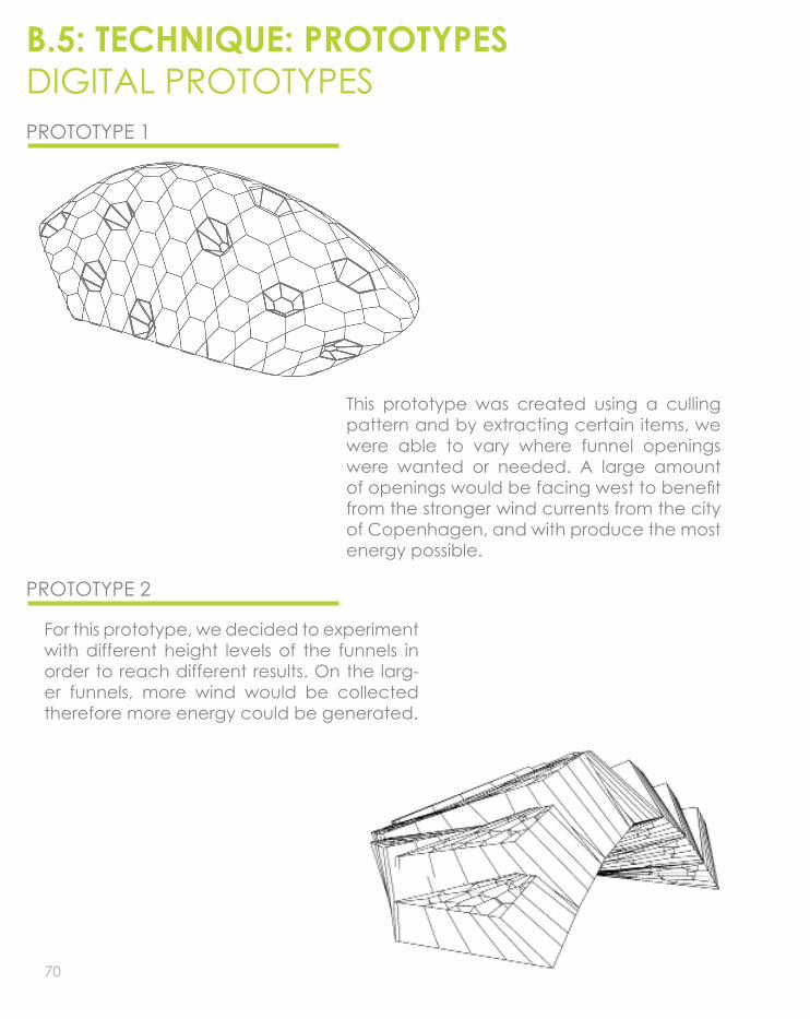
B.5: TECHNIQUE: PROTOTYPESDIGITAL PROTOTYPESPROTOTYPE 1
PROTOTYPE 2
This prototype was created using a culling pattern and by extracting certain items, we were able to vary where funnel openings were wanted or needed. A large amount of openings would be facing west to benefit from the stronger wind currents from the city of Copenhagen, and with produce the most energy possible.
For this prototype, we decided to experiment with different height levels of the funnels in order to reach different results. On the larg-er funnels, more wind would be collected therefore more energy could be generated.

71
PROTOTYPE 3
PROTOTYPE 4
This prototype is the result of a hexagonal structure with funnels as openings. It can be used to generate energy through the fun-nel openings which would capture wind. This digital prototype shows a large amount of openings, which might interfere with the amount of wind that would actually go through the funnels. Such a large amount of openings makes the design lose its aesthet-ics, it just looks like a rib structure.
The number of openings was decreased for this prototype. It looks more aesthetically ap-pealing given that it has larger openings. If this larger openings are positioned to face west direction, then a lot more of energy would be generated because of the stron-ger wind currents.

72
B.5: TECHNIQUE: PROTOTYPESITERATIONS FOR PHYSICAL PROTOTYPES
PROTOTYPE 1
Voroni offset and loft between the two

73
PROTOYPE 2
3 piece cell assembly, structural and form tests.
PROTOTYPE 3
Detail prototype of a hexagonal cell and funnel with rotating panel

74
B.5: TECHNIQUE: PROTOTYPESPHYSICAL PROTOTYPES
We decided to make several proto-types to test different features of our future design; such as structure and form, height, movement, lights and shadows, amongst others.
We experimented with two different methods to test the form of our de-sign, this can be seen in prototypes 1 and 2, and one to test the structure and movement.

75
PROTOTYPE 1
PROTOTYPE 2
PROTOTYPE 3

76
MODEL MAKING PROCESS
This prototype was created to test the form that could be used to develop our design.
The main form is a group of voronoi cells that decreases its diameter to-wards the back, creating the idea of funnels.
The material used for this prototype is white ivory card. The digital pro-type was unrolled and printed in the FabLab. It was successful in assem-bling the small scale model; howev-er, we realized that a stronger and heavier material should be used if the model was intended to be created in a larger scale.
We were happy with the easy assem-bly of the prototype.
This prototype does not need a sep-arate structural element, the different voronoi cells become the structure.
The Rhino file for this model shows a flat base, but as a result of our exper-imentation we realized that the form arches naturally because of the lack of downward forces to create a flat surface. Perhaps if a heavier material was used, then the prototype would have resembled more the computer design.
It should also be taken into considera-tion the way it is joined to the ground. If this is applied, then perhaps a light material could be used becasue enough forces would take place. The finished outcome of the physical pro-type, aothough different to the grass-hopper model, is aesthetically appe-alling and has a more organic and natural look than the digital model. We are satisfied with the end result of the prototype.
We also experimented with the use of light and how it would create shad-ows from the openings
B.5: TECHNIQUE: PROTOTYPESPROTOTYPE 1

77

78
B.5: TECHNIQUE: PROTOTYPESPROTOTYPE 2
With this prototype, we tested an as-sembly process that would not need a separate structural frame, but be able to be self stand thanks to the cells that would be joined one next to the other.
We tested how a funnel inside of an offsetted funnel could be assembled and connected to another funnel cell with similar shape, allowing them to be easily constructible and assembled one next to each other.
we tested as well how through the openings, views could be framed in order to provide a more engaging at-mosphere between design and users.
We also experimented with the use of light and how it would create shad-ows from the openings.
The design is aesthetically appealing. We also tested how scale would im-pact the design. Large cells look dom-inant, but at the same time would be able to engage with the users. The openings would be used not only to allow wind to go through and gener-ate energy, but also to frame views of the surrounding environment. This would provide a different level of en-gagement between design, site and user.
MODEL MAKING PROCESS

79

80
B.5: TECHNIQUE: PROTOTYPESPROTOTYPE 3
This model allowed us to experiment mainly with structure.
It is a detailed model of one of the hexagonal cells with a funnel.
With it we experimented how the funnel could join the hexagonal cell structure, and ways on which the in-ternal panel could be attached to the funnel. We were not satisfied with the result. It was difficult to build giv-en the different angles the hexagonal cell presented. We will try to fix this by creating flat hexagonal panels so as-sembly is easier, if this is the proposal to continue developing.
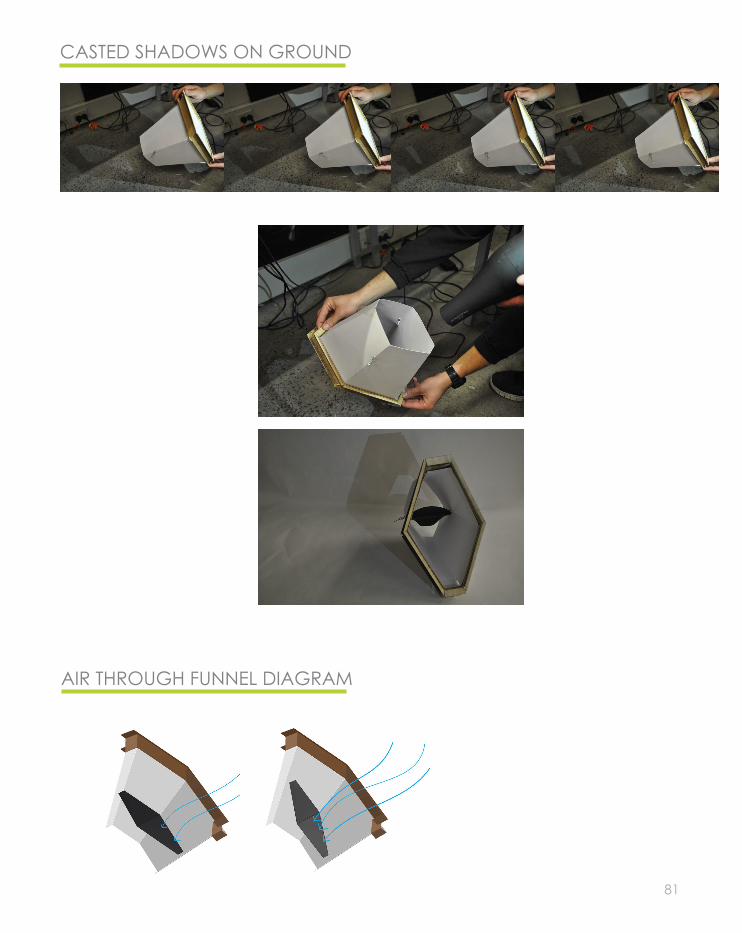
We also experimented with the pres-ence of wind, how would the panel rotate if wind loads are applied to it. It was a successful experimentation, but the design needs more refinment because the internal panel is flapping against the funnel surface whenever it rotates and this is given because of the irregular shape of the hexagonal cell. All of these experimentation can be seen in the photo sequence showing the different shadows on the ground, created by the rotating internal pan-el. This was achieved with the use of a blow dryer making the internal pan-el rotate, and photographing the se-quence of shadows created by the rotating panel on the floor.
MODEL MAKING PROCESS
81
CASTED SHADOWS ON GROUND
AIR THROUGH FUNNEL DIAGRAM

82
B.6 TECHNIQUE: PROPOSAL
The technique we developed to produce a design proposal referred to the idea of ‘making the invisible visible. We intend to have openings created by fun-nels from which energy would be generated by the wind. Although energy generation is the main focus of the design brief, we wanted to explore a way in which we could use the funnels not only to gener-ate energy, but also to frame views of the surround-ing environment, raising awareness of sustainability that is currently being practiced in Copenhagen. We intend to be able to frame for instance the wind turbines located at the northeast of the site, or the changing sea levels to also raise awareness of cli-mate change.
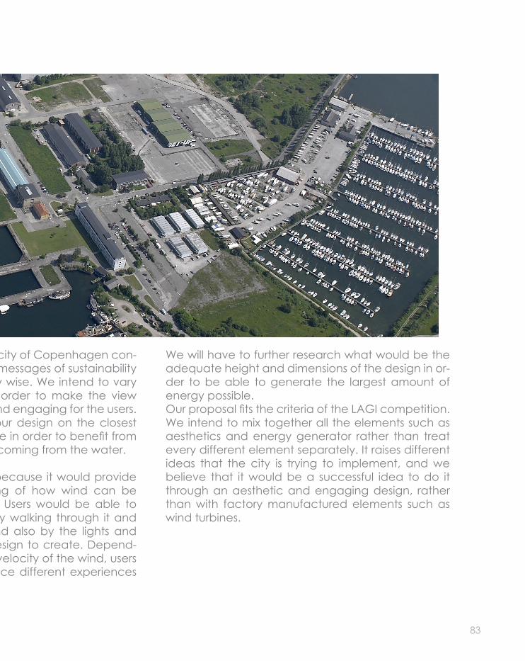
This design would help the city of Copenhagen con-tinue transmitting all these messages of sustainability they are implementing city wise. We intend to vary the sizes of the funnels in order to make the view framing more appealing and engaging for the users. We decided to allocate our design on the closest area to the water of the site in order to benefit from the stronger wind currents coming from the water.
It is an innovative design because it would provide the users an understanding of how wind can be used to generate energy. Users would be able to engage with the design by walking through it and experiencing the wind, and also by the lights and shadows we intend the design to create. Depend-ing on the frequency and velocity of the wind, users might be able to experience different experiences in the one site.
83
We will have to further research what would be the adequate height and dimensions of the design in or-der to be able to generate the largest amount of energy possible. Our proposal fits the criteria of the LAGI competition. We intend to mix together all the elements such as aesthetics and energy generator rather than treat every different element separately. It raises different ideas that the city is trying to implement, and we believe that it would be a successful idea to do it through an aesthetic and engaging design, rather than with factory manufactured elements such as wind turbines.
This design would help the city of Copenhagen con-tinue transmitting all these messages of sustainability they are implementing city wise. We intend to vary the sizes of the funnels in order to make the view framing more appealing and engaging for the users. We decided to allocate our design on the closest area to the water of the site in order to benefit from the stronger wind currents coming from the water.
It is an innovative design because it would provide the users an understanding of how wind can be used to generate energy. Users would be able to engage with the design by walking through it and experiencing the wind, and also by the lights and shadows we intend the design to create. Depend-ing on the frequency and velocity of the wind, users might be able to experience different experiences in the one site.
84
B.6 TECHNIQUE: PROPOSAL

85

86
B.7 LEARNING OBJECTIVES AND OUTCOMES
The interim feedback given to our proposal consisted on not re-straining ourselves into the pavilion shape, but extending over the site and thinking of other ways to allo-cate our design in order to bene-fit the most from the wind. Perhaps we could follow the idea experi-mented with prototype 2, where we joined together a number of cells and made an irregular verti-cal shape, rather than an enclosed pavilion. If we choose to follow this proposal, we would have to con-sider height and placement of fun-nel openings in order to benefit the most from the wind. This idea could also be used to frame views of the surrounding environment; it is some-thing to be further developed. We also need to consider further how much energy would be generated with this energy generator meth-od; if the winds reaching the site are enough to be able to generate any energy at all.
The prototypes we assembled gave us an understanding of how the dif-ferent elements would be able to be constructed, and what sort of materials would be more successful to be used. However, this should be further developed. I believe we gained a vast amount of knowledge, not only digital mod-el making wise, but also about site, materiality and needs throughout this exploration; and I believe that we have an interesting and ap-pealing idea to be further devel-oped in the remaining time of the semester.

87
88
B.8 APPENDIX-ALGORITHMIC SKETCHES

89
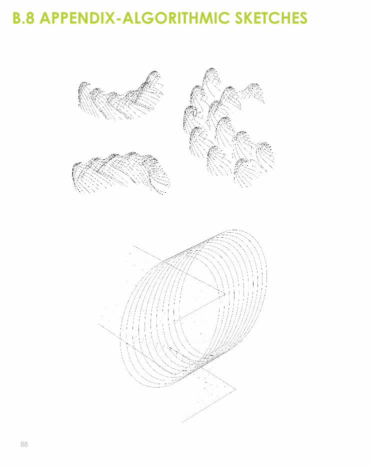
I continued to gain knowledge and understanding of the software throughout the weekly tutorials, as well as through my own development for both case studies 1 and 2, as well as in the creation of our proposal. I believe I’m still learning, but I am starting to feel more confident with what I’m doing. I am starting to understand how the programs work, rather than just learinng commands. It is a knowledge that I hope I further develop by the end of the semester.

90

91
PART C

92
C.1 DESIGN CONCEPT CONCEPT REVIEW
Deriving from the feedback given in the PART B presentation, we decided to make a few design decisions and considerations with our proposal idea. We were asked to consider the layout of the design and extend throughout more of the site area, rather than re-stricting ourselves with a pavilion utilis-ing a small area of the site. We were also asked to consider furthermore the way the wind turbines would be inte-grated with the design, and how they would function.
The new design proposal consists of a series of free standing ‘wall like’ struc-tures, located on the south west cor-ner, and extending all along the west and south axis. We decided to choose this location in order to benefit the most from the south west winds, which are the strongest wind currents from the site. With this proposal, it allows us with the flexibility to occupy more area of the site rather than just concentrat-ing in one small portion of it, and this allows us to make a more engaging proposal to the users with more detail into the site placement of the design elements.
We intend to have several structures which’s functions are to frame views, generate energy through a wind tur-
bines system, and shelter users from wind currents, allowing them to enjoy the design and the site. We intend to provide the users with a design that would make them raise awareness about the emphasis that the city of Copenhagen is putting on sustainabil-ity.
To help raise this awareness of sustain-ability, we are using the openings on the structure to frame views of the city, not only cultural but also environmen-tal. We intend to frame the turbines to show emphasis on sustainability, as well as openings facing the water to emphasize on the rising sea levels and climate change; as well as cultural en-tities such as the little mermaid sculp-ture located far on the horizon on the other side of the city.
The layout of the structures resembles the idea of a maze, which creates a degree of uncertainty and mystery for the users; and by this, it allows them to engage more with the site. The topog-raphy of the site will be modified; it will be raised higher in the areas that the design is located, to emphasis on the design, and also to differentiate it from the open area we intend to leave open to be enjoyed by the users as a recreational open area.

93
This diagram shows the place-ment of the refined design in the site. Surrounding context is showed as well to show how the area is surrounded by a busy industrial area of the city. Our design proposal layout seen to the right is con-tradicting compared to its surroundings. It shows organic shape structures strategically positioned in site. It looks in-teresting and appealing, and we intend for users to be in-trigued by it and feel invited to walk through and in be-tween the structures.
The first diagram to the left shows the refined design in site, with the contour lines, and the arrows represent the di-rection of the dominant winds, show-ing that the largest wind current is from the south west, but that it could be ex-panded all the way to the north west with smaller wind currents.
The bottom diagram to the left shows how exposed to wind the site is. The design proposal acts as a wind barri-er to a large area of the site, and this is represented in blue; the areas ex-posed to wind are represented in rred

94
Base curves
‘losoe’ loftedsurfaces
pattern and form
opened funnels
funnels w/turbine panels
C.1 DESIGN CONCEPT PSEUDO CODE
95
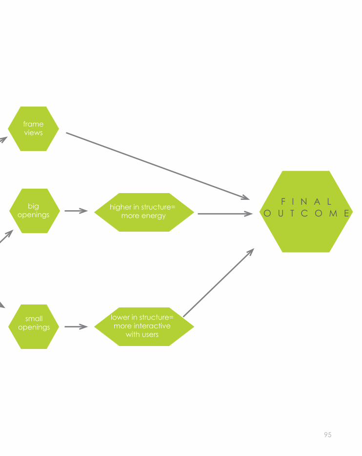
frame views
big openings
small openings
F I N A L O U T C O M E
higher in structure= more energy
lower in structure=more interactive
with users
96
C.1 DESIGN CONCEPT DESING ITERATIONS
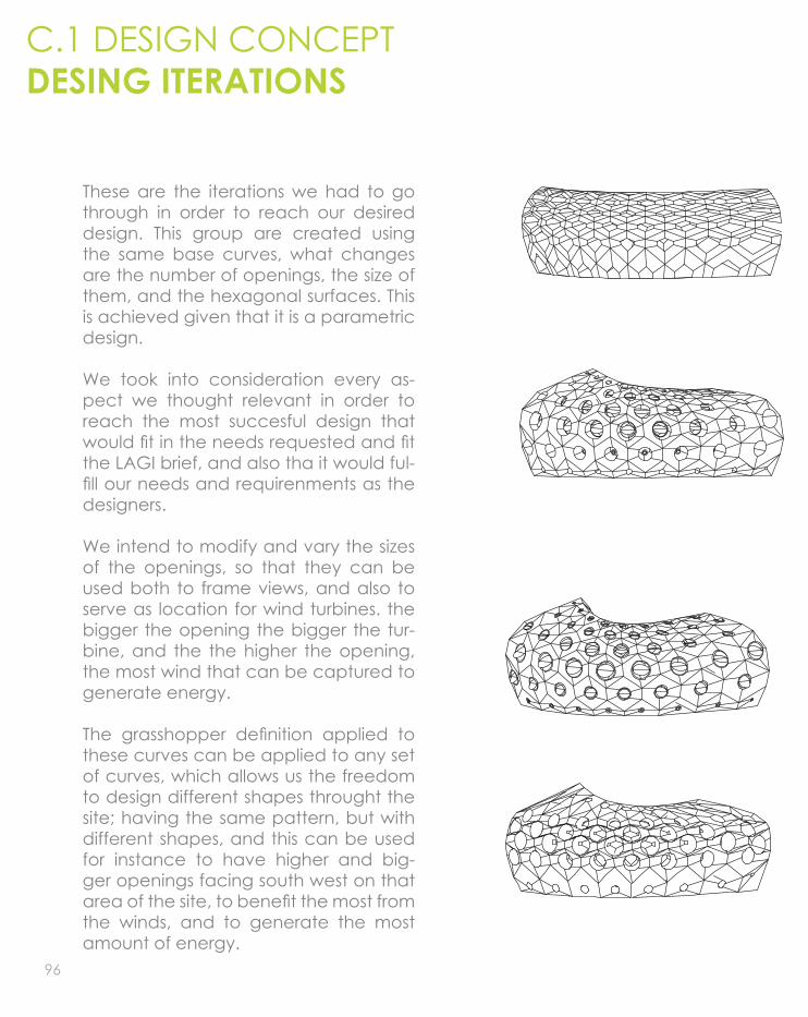
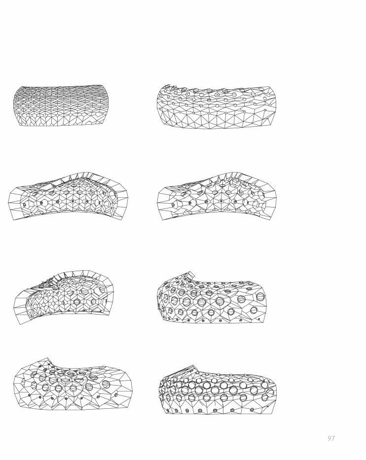
These are the iterations we had to go through in order to reach our desired design. This group are created using the same base curves, what changes are the number of openings, the size of them, and the hexagonal surfaces. This is achieved given that it is a parametric design.
We took into consideration every as-pect we thought relevant in order to reach the most succesful design that would fit in the needs requested and fit the LAGI brief, and also tha it would ful-fill our needs and requirenments as the designers.
We intend to modify and vary the sizes of the openings, so that they can be used both to frame views, and also to serve as location for wind turbines. the bigger the opening the bigger the tur-bine, and the the higher the opening, the most wind that can be captured to generate energy.
The grasshopper definition applied to these curves can be applied to any set of curves, which allows us the freedom to design different shapes throught the site; having the same pattern, but with different shapes, and this can be used for instance to have higher and big-ger openings facing south west on that area of the site, to benefit the most from the winds, and to generate the most amount of energy.
97

98
C.1 DESIGN CONCEPT DESING ITERATIONS
When we first sterated thinking of de-sign proposals, we experimented with the idea of having a central structural element which’s main focus and func-tion would be to generate energy. This structure would be big in dimensions and taller than the other structures, but with the same alrgorithmic definition, so it blends with the surrounding structures and is aesthetically appealling.
We experimented with different forms and base curves for this main struc-ture, but we could not reach a design we all agreed on being successful. This two proposals do not engage with the wall like structures previously discussed; therefore the idea was discarded and we all decided that a new approach should be taken
DISCARDED IDEAS
These two images to the right show the possible site layouts we could have chosen if we had decided to apply this idea of a central elements as the main focus of our design. Through the layout iterations we realized that there was no coherence between the wall like struc-tures and the central structure, that is why we decided to develop another approach to our design proposal.

99
We also explored with incorporating this type of convential turbine, but we real-ized that it gave the design an industrial look. At the beginning, we thought we could make it work given that the de-sign is located in an industrial area, but then it does not look like a sculpture or installation that is described in the LAGI brief. This drove us to make the decision of using the rotating panels, as it gave the design an original and appealing look.
the three site diagrams to the right show different design iterations we created that represent the positioning of the wall structures in order to benefit the most from the wind currents. None of them are succesful given that the main function of these structues is to gener-ate energy, and many of the structures are being obstructed by others, which would result in not enough wind reach-ing all of them in order to generate en-ergy. This is a factor we had to consider with the final layout of our design.

100
C.1 DESIGN CONCEPT FINALISED CONCEPT
For the final design proposal, we decid-ed that for the main feature or structure of the design, we would keep the or-ganic wall approach rather than a cen-tral incoherent element.
This wall would be facing south west where the strongest wind currents come from. This wall will be much taller than the other structutal elements, meaning that it will be able to reach strongest wind currents, and with larger open-ings and turbines, generate the most amount of energy. We also saw that winds are stronger from the south west, but throughout the year, this direction varies all the way to north west. With this organic tall wall structure, we can position it to face and extend through-out the whole west axis of the site, and with this ensure the most optimal energy generation as possible. This structure is now coherent with the rest of the de-sign, following the idea of organic wall structures; and this is a factor that will contribute to the users’ engagement with the site and the design.
All the wall structures are different from one and other, but they all have the same algorithmic definition applied to them, making them all seem connect-ed and part one design as a whole.
This can only be achieved given that it is a parametric design, with many vari-able factors that can be modified and adapted depending on the required needs.
The sizes vary from large high dimensions such as 16m close to the south west, to much smaller dimensions such as 3m high to the south east corner, which is the area from which users would enter the site and design proposal. The height of the structures gradually decreases from west to east.
Wind turbine panels are located in the funneled openings of the structures, and their diameter also varies depending on its positioning on the site. The highest wall located on the south west corner would have openings of almost 2m in diameter at its highest points, to benefit the most from the wind currents, where-as the openings located throughout the south axis decrease in size to almost .25m in diameter. Some of the openings will be left empty without turbine panels so they serve as view framers for users to view through them, this will allow them to interact furthermore with the design.

101
Perspective view of the design proposal
South Elevation
North Elevation

102
C.1 DESIGN CONCEPT ENERGY GENERATION
The chosen technology consists of a costume made unconventional wind turbine system, where each turbine is located in the funnel openings of the structures. The inspiration for this idea came from a researched cos-tume made turbine1 that functions in a similar way to what we intended to achieve.
month daily average wind speed power air Turbine Power (W per second)
lowest (kph) mean(kph) highest (kph)
Coefficient density
r=0.25m/A=0.22m2 r=0.5m/A=0.79m2 r=0.75/A=1.767m2January 11.3 22.5 33.8 0.4 1.285 12.55 49.57 110.87Feburary 10.5 20.9 30.6 0.4 1.285 10.06 39.74 88.86March 9.6 20.9 29 0.4 1.285 10.06 39.74 88.86April 7.7 19.3 27.4 0.4 1.24 7.64 30.19 67.52May 7.7 17.7 25.8 0.4 1.24 5.90 23.30 52.09June 7.7 17.7 25.8 0.4 1.24 5.90 23.30 52.09July 7.7 16.1 24.1 0.4 1.19 4.26 16.81 37.61August 8 16.1 24.1 0.4 1.19 4.26 16.81 37.61September 8 17.7 25.8 0.4 1.24 5.90 23.30 52.09October 9.6 20.9 27.4 0.4 1.24 9.70 38.35 85.77November 10.5 22.5 30.6 0.4 1.285 12.55 49.57 110.87December 10.5 22.5 32.2 0.4 1.285 12.55 49.57 110.87
The table below shows all the calcula-tions and research applied in order to determine an average of the energy that our design would generate.
The formula followed to determine the values Power Values is2:
P=(1/2) x air density x Area of turbine x wind speed^3 x Power coefficient
where Cp is a constant value, and air density constant depending on the month and season. The table shows 3 end results, that were achieved by applying different area values into the formula, given that the diameter of the turbines throughout the design varies.

103
JAN
FEB
MA
RA
PR
MAY
JUNJUL
AUG
SEP
OC
T
NOV
DEC JAN
FEB
MA
RA
PR
MAY
JUNJUL
AUG
SEP
OC
T
NOV
DEC
ENERGY GENERATED:
• PER MONTH • ALL YEAR AROUND
The table shows that it is diffuclt to get an accurate amount of energy that would be generated because of the different variables that have to be taken into consideration. Scale, wind velocity and orientation may vary the results, and these are unpredictable variables.
The diagram above shows the aver-age amount of energy produced per tutbine per month, showing that the largest amount of energy generated will take place during winter, and its values will decrease in summer given that wind currents are not very strong.
The second diagram above shows the average taken of the whole year of a single turbine, and it also shows that a vast amount of energy would be gen-erated on average, even though the changes between summer and winter are so drastic.
On average, one turbine would pro-duce 2kWh, and roughly 1GW in a year, meaning that it would provide enough energy for the average 2 people according to the Danish Ener-gy Savings3.
Very roughly, the whole design would-produce around 80GW throughout the year, but hard to determine a concrete number given the different variables.

104
C.2 TECTONIC ELEMENTS
The main requirenments for our funneled cell system are the allowance of flexibili-ty between the joints in the funnels and the ability to restrain strength. Only by achieving this, the panels of the funnels will be able to be folded into the right position, as the one found in the digital models. To achieve this, we experiment-ed with different joint approaches, but the most successful was the tail joint, as it provide strengths from the same ma-terial and does not require complicat-ed assembling procedures. A diagram of this can be found above.
Funnel dove and tail joint
Feedback from tutors suggested the presence of secondary structures for support, because the timber by itself would not be able to be self supporting. This secondary structure would connect all the cells and funnel elements togeth-er and keep them in place. This could be achieved with steel.
On the previous design proposal, we at-tempted to integrate the rotating pan-els in an irregular hexagonal shape, but through prototype testing we all agreed that it was not a successful idea. To fix this, we decided to use circular open-ings rather than the irregular hexagons. With the circular sturctures, the panels are able to rotate freely in position with the wind.

105
Above is a refined representation of the tectonic assembly of three funneled cells our design. Note the differences in materiality, where timber is the dom-inant material, steel represented black works as secondary supports, and alu-minium represented grey for the turbine panels inside the funnels.
This diagram shows an exploded view of all the elements, showing the main three components that form each cell. This three elements are the folded exter-nal surface, the internal funnel and the internal smooth facade, With this kind of vidual representation it is easier to un-derstant the assembly process this de-sign would have to go through if it was to be built.

106
C.2 TECTONIC ELEMENTS The diagram below is an exploded sequence representation of all the elements form-ing each individual cell, and what we consider that is needed in order for it to be able to support itself .
Exploded turbine ring and panel

107
The diagram to the left is an exploded representation of the elements that form the turbine panel and the ring it is supported in so it can rotate.

108
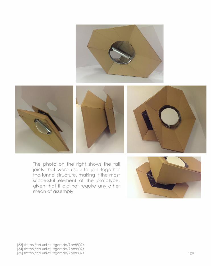
We got inspiration for the assembly of the timber panels from the ITKE/ICD Re-search Pavilion4 on the assembly pro-cess it follows and the joints between the timber panels creatied using tail joints.
We approached this technique and created a successful construction pro-totype of an individual cell. It was con-structed with MDF and laser cut in the FabLab, at a scale of 1:5.
We experienced some difficulties when assembling the prototype, such as hold-ing the curved surface in position where the ring for the turbine is located. From this outcome, we decided that the cor-ners had to be chamfered in order for all the panels to sit in position and not collapse when they were not being hold.
The tail joints used in the funnels worked successfully in the assembly process; the funnel held in position with no extra structural elements.
The prototype has the basic three tim-ber structural elements discussed be-fore, the inner facade, the funnel and the cirved surface where the turbines are located, and they can be easily dif-ferentiated. The prototype also has the metal ring where the turbine panel is placed, and a representational turbine that rotates successfully in position on
C.2 TECTONIC ELEMENTSPHYSICAL PROTOTYPE
assembled timber panel [33]
joint detail-tail joints [34]
assembling process of a single panel [35]
109
The photo on the right shows the tail joints that were used to join together the funnel structure, making it the most successful element of the prototype, given that it did not require any other mean of assembly.
[33]<http://icd.uni-stuttgart.de/?p=8807>[34]<http://icd.uni-stuttgart.de/?p=8807>[35]<http://icd.uni-stuttgart.de/?p=8807>

110
C.2 TECTONIC ELEMENTS MATERIALITY
Timber Products Company produces a variety if timbers that are attractive and versatile5.
The selected timber is cost effective, light weight and strong. This character-istics will benefit our design given that they will make it constructible, and this will help minimise the loads given that weight is reduced, and also that less structural elements will be needed to support heavy loads. The material thickness is 20mm. This thickness is ide-al for our design given that it allows the flexibility required for it to be able to not just hold the design, but also to be able to angle and fold into position with the funnel openings.
OKOUME VENEER HARDWOOD PLYWOOD
With our material choices, we focused on finding sustainable and durable materials, that would suit the sustainable approach the city of Copenhagen is implementing. We also focused our research on trying to find local sustainable materials, and we suc-ceeded with this research.
the selected plywood will be used in most of the design. It will be used on the funnel openings and overall look of the design proposal.
The manufacturing of the selected timber is environmentally friendly and sustainable. the product is coated with RhinoCoat, which helps it reduce emissions and also enhance the qual-ity of it6.
The selected timber is certified by the SFI (Sustainable Forestry Initiative) and the FSC (Forest Stewardship Council)7. This helps us transmit the message of sustainability and environmental care through our design proposal.
selected timber profile [36]

111
COLD-FORMED STEEL
It will be used for the secondary sup-porting structure of the design propos-al. We chose it because it provides the flexibility required in order to adjust to the multi-angle elements that will need its assistance for support8.
This type of steel is much lighter in weight when compared to other types of steel, but at the same time strong; which is a property we need with our design.
This specific material will help us pro-mote the message of sustainability we intend to transmit through our design and materiality.
The ideal thickness required is around 5mm thick. With this thickness, steel will be able to maintain the structural in-tegrity of the design, and it wont com-promise the spacing between the cells that are constructed in timber.
This steel will also be used for the ring system needed for the turbine panels, and thickness will also be around the 5mm.
ALUMINIUM
Aluminium is used in the costume made wind turbine panels. It is a light weight material that can be support-ed in the timber openings with the steel support, and it is capable of easiliy rotating with the wind forces to generate energy from it9.
steel representation [37]
aluminium representation [38]
[36] <http://www.timberproducts.com/Products/Hardwood_Plywood/>[37]<http://www.tatasteeleurope.com/showproductsection?PRODUCT_ID=1&PRODUCT_TYPE_ID=2&DISPLAY_IPAD_PAGE=NO>[38]< http://www.realityinscale.com/epages/61537336.sf/en_US/?ObjectPath=/Shops/61537336/Products/ACC006>

112
C.2 TECTONIC ELEMENTS CONSTRUCTION PROCESS DIAGRAMThe diagram found below shows the construcution process our proposal would have to follow if it was to be built.
OFF SITE ON SITE
Fabrication of plywood panels and
funnels*
Fabrication of metal
turbine panels
Terrain fixes:
excavation
Fabrication of steel angle frames All for one cell
+
+
* Special care should be applied to the prefabrication of the timber funnels
given that the material should be folded and chamfered to a particular angle in order to meet the same characteristics
and shapes as the digital design.
+Individual cells
transported by truck to site
Interior plywood face connected to funnel
to hide wirng & internal structure*
Final Construction of one sculptural wall

113
ON SITE
Terrain fixes:
excavation +Individual cells
transported by truck to site
Cells connected to each other by an internal structure
Interior plywood face connected to funnel
to hide wirng & internal structure*
Wiring for turbines connected to grid central grid point+ +
+
=Final Construction of one sculptural wall
*Special care should be applied in the construction order given that the design has many individual parts that could be easiliy mistaken. Labelling would be of great help when assembling each indivual structure.

114
C.3 FINAL DESIGN 1:500 physical site model This model is a representation of the layout of our design in the site, at a scale of 1:500. In it, we show the topography changes where the areas that the design is positioned are elevated to emphasize on it, the layout and how the design occupies the site, and the contours of the site surrounding including the water.

115

116
C.3 FINAL DESIGN RENDERS OF DESIGN IN SITE These images show a digital representation of the design, positioned in the site and its context, showing materiality and dimensions compared to the surrounding site.

117
118
C.4 ADDITIONAL LAGI BRIEF REQUIRENMENTS
The aim of our design proposal is to emphasize in sustainability, and how it is being practiced and achieved throughout the whole city of Copen-hagen. From the LAGI brief, we decid-ed to design an installation that con-sists of a series of ‘wall like’ structures, located on the south west axis, and extending all along the west and south axis. This location was chosen given that the most dominant winds come from this direction, and we intend to use wind as our energy resource.
The design consists of a series of struc-tures which’s function is to frame views through the openings, generate ener-gy through a wind turbine system, and shelter users from wind currents, allow-ing them to enjoy the design and the site.
The different walls vary in height and shape, to fulfill different functions. • on the south west corner, walls ex-
tend the highest in order to benefit from the strongest wind currents.
• along the south area of the site, walls are positioned in a ‘maze like’ layout, which will be engaging for the users.
The topography will be raised along where the design is located, to make empphasis on it.
The chosen technology consists of a costume made unconventional wind turbine system, where each turbine is located in the funnel openings of the structures.
Given the structures layout, variable dimensions of the turbines deisgn wise, and changing wind velocities both in speed and direction, it is very difficult to reach an accurate value for the amount of energy that would be gen-erated.
The turbine rotates on a horizontal axis. The reason for this is that our turbines will need to accommodate the func-tion of generating energy and also framing views for users. This type of tur-bine does not produce much noise, which will be appreciated by users who intend to enjoy the design.
On average, one turbine would pro-duce 2kWh, and roughly 1GW in a year
Very roughly, the whole design would-produce around 80GW throughout the year, but hard to determine a concrete number given the different variables.
PROJECT DESCRIPTION USED TECHNOLOGY
ESTIMATED ANNUAL kWy

119
The main material perceived from the design is timber. The chosen timber is Okoume Veneer Hardwood Plywood because of all the characteristics it brings to the design. The overall look and finish of the design will be with this type of timber. The thickness of this timber will be 20mm.
Cold formed steel is used for the sec-ondary supportive structures beneath the timber, to enhance the structural stability. The thickness of the steel will be 5mm.
The last main material used in the de-sign is aluminium, present in the cos-tume made turbine panels and it was chosen given that it is a light material that allows the turbine panels to rotate with the wind currents. The thickness of the rotating panels will be around 10mm, where the panels can vary in diameter sizes from .25m to 1.5m de-pending on the location and the size of the opening.
The design occupies a large amount of area on the south and west axis, extending logintudinally on these two borders. The wall structures are roughly 1 to 1.5m thick, depending on the size of the turbine that is positioned with-in the structure. Each wall structure is unique and varies according to the needs it intends to accommodate.
We intend our final design to be a mean of sustainable education for its users. We want to raise awareness of sustainability to its users through a wind turbines system, where users can learn through visualizing how the tur-bines work, as well as to be able to en-joy the site and the design. All the ma-terials chosen for the fabrication are environmentally friendly and locally made, and they all have long lasting span amount of time to be functional, meaning that replacement of mate-rials should not be required for years. With our design proposal, we intend to invite users and visitors to not just come to the site to view the design and leave. On the contrary, we intend to make of the site a recreational area that would be enjoyed by anyone, does not mat-ter the age. With this idea, we invite users to interact with the design, and with this understand and learn how the wind turbines function to generate energy. Integrated with the design, some areas provide seating locations, where users could stay for an amount of time and appreciate a close look of the design. If this is not what they in-tend on doing, a large open area was left that can be used for recreational activities such as picnics or family ac-tivities. From this large open area, the design can be appreciated and users can still learn and educate themselves of how the wind turbines are function-ing to generate energy and create an environmental impact towards a sus-tainable city.
PRIMARY MATERIALS & DIMENSIONS ENVIRONMENTAL IMPACT STATEMENT

120
C.5 LEARNING OBJECTIVES AND OUTCOMES OBJECTIVE 1It was necessary for us to interrogate the brief in order to understand the tasks we were set to undertake. By interrogating the different elements the brief outlined, we were able to design an engagig design proposal that, does not just fit the LAGI brief requirenments, but the approaches the city of Copenhagen is undertaking towards sustainability. Interrogating the brief was not enough to be able to design a successful design proposal, without the context of the city it is going to be located.
OBJECTIVE 2 As a result from desiging a parametric design, we were able to modify and work on the grasshopper definiton enough to create different results and iterations, that sometimes would be successful outcomes and be part of the finished design. By experimenting with our algorithmic design, we were able to create an engaging and interesting design proposal, that is not just appealling, but fits the requirenments of the LAGI brief. We did not have a set idea of what we intended to do with our design ideas, but through experimenting with the parametric design we were able to reeach a successful final outcome, that could only be created through parametric design.
OBJECTIVE 3Our parametric approach led us to develop a series of three dimensional iterations that we intended to include in our design as the wall structures. Through 3D modelling, we were able to digitally visualize the final outcome of our desired design, not only as the design, but how it would be positioned in the site; and also how natural elements such as sun light would affect the design proposal during different times of the day. This objective provided us with the knowledge to digitally visualize the design in site and how natural elements interact with it.
OBJECTIVE 4Throughout this object we realized that the digital model sometimes differ from a built structure. We understood this by the production of prototypes with different materials. The main thing that I found fascinating is the fact that digital model mate-rials do not have any weight, they are jsut free standing. Throughought the fabrication of the prototypes, different material weights would give different outcomes, sometimes even colapse because the structure is not self supporting when exposed to material weight. By prototyping, we were able to fix and improve design features for the final outcome in order to make it as accurate and realistic as possible.
OBJECTIVE 5Through the creation of diagrams and tables, we were able to visually transmit our design intentions and proposals. Critical thinking was required when stating some of our arguments, facts and ideas. In order to do this, extensive research had to be made in order to provide a convincing argument. This can be seen in the energy generation calculations and results for instance.
OBJECTIVE 6Through the research of precendents and built examples to serve as inspiration for our design, I was able to understand how parametric design is put into practice by learning and researching built examples. This aquired knowledge was then incorporated in our final design proposal and ideas.
OBJECTIVE 7One of the most important things I learnt is the difference between computarisation and computational design. Knowing this difference, I was able to understand how computation works. Throughout the semester I was exposed to this new design approach, created using the software Rhino and its plugin Grasshopper. By using the software, we realized as a group that computation facilitates the development of this kind of designs, but at the same time it could bring up technical problems that in occassions, we did not have the knowledge to fix. OBJECTIVE 8By using the software throughout the semester, I developed an understasnding of computational geometry and data struc-tures. This aquired knowledge will be further developed in future design studios I understake. I know that it is a tool that will be beneficial for my future career if I intend to stay in the field, but before I feel confident with my skills, I need to learn and understand furthermore the software and the ideas behind it.

121

122
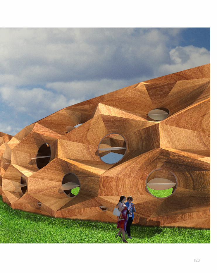
123

124
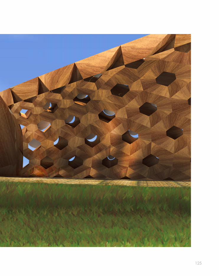
125

126
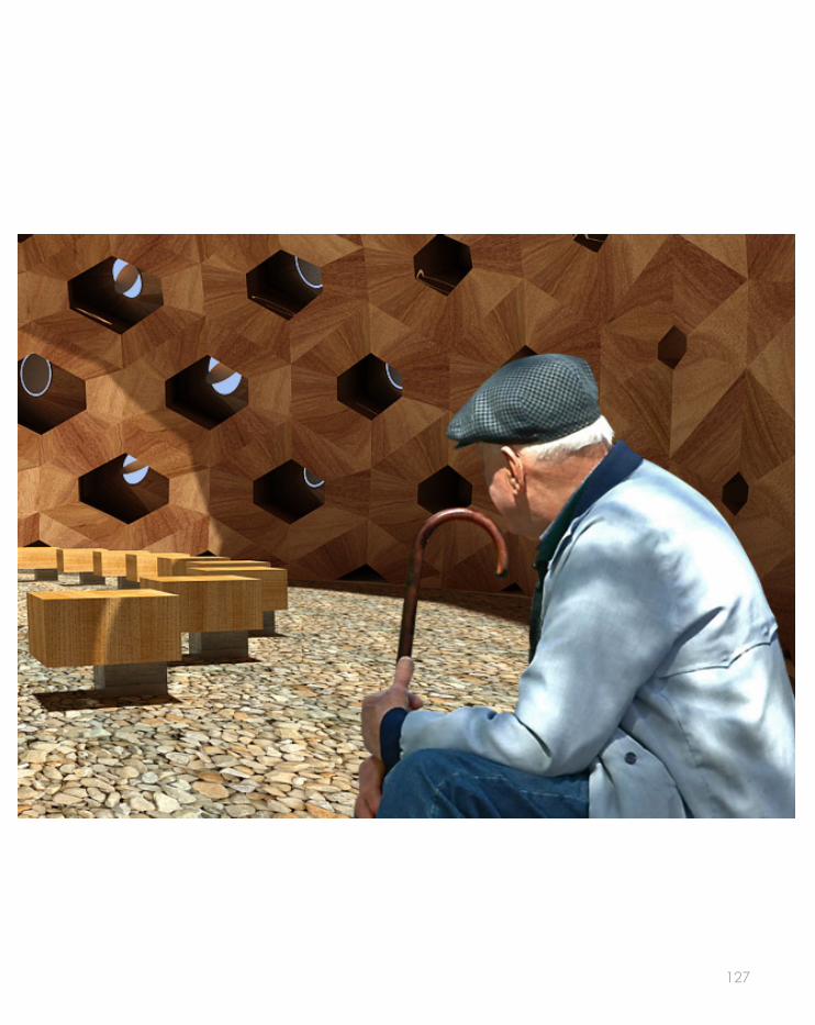
127

128

129

130
APPENDIX-ALGORITHMIC SKETCHES
We aimed to create for our design proposal an algorithmic definition that was parametric enough to modify each wall structure and to make them all unique in their own way. Elements that are subject to change are the size of the openings, the amount of open-ings, the variation between the sizes in an indivudual design, amongst others. We were allowed to vary the design according to what we intended.
The algorithmic definition is applied to base curves that are named from Rhi-no; the finished outcome will look dif-ferent with each different set of curves.
A lose loft was applied to the set curves, giving the overall composition of the design a more organic look, and not restricted in the exact bound-aries of the curves.

131

132
REFERENCES PART A
TEXT
1. Robert Ferry & Elizabeth Monoian, Land Art Generetator Initiative, assessed 10.03.14 <http://landartgenerator.org/contact.html>
2. ‘Circle and Patch’, Timothy Wai, Cheng Lai Victor Huang, Land Ar Generator Inititive, assessed 10.03.14 < http://landartgenerator.org/LAGI-2012/WH181390/>
3. Robert Ferry & Elizabeth Monoian, ‘a field guide to renewable energytechnologies’, land art generator initiative, p.33
4. Robert Ferry & Elizabeth Monoian, ‘a field guide to renewable energytechnologies’, land art generator initiative, p.26
5. Brady Peters, ‘The Building of Algorithmic Tought’, AD Journals, Volume 83, Issue 2, p.8-15
6. Brady Peters, ‘The Building of Algorithmic Tought’, AD Journals, Volume 83, Issue 2, p.10
7. Jürgen Mayer H, ‘Metropol Parasol, Seville’, AD Journals, Volume 82, Issue 5, p.70-73
8. Jan Knippers, ‘From Model Thinking to Process Design’, AD Journals, Volume 83, Issue 2, p.74-81
9. Definition of ‘Algorithm’ in Wilson, Robert A. and Frank C. Keil, eds (1999). The MIT Encyclopedia of the Cognitive Sciences (London: MIT Press), pp. 11, 12
10. Jan Knippers, ‘From Model Thinking to Process Design’, AD Journals, Volume 83, Issue 2, p.78
11. DesignBoom Architecture, assessed 26.03.14, < http://www.designboom.com/architecture/soma-one-ocean-thematic-pavilion-for-yeosu-expo-2012-complete/>
12. Jan Knippers, ‘From Model Thinking to Process Design’, AD Journals, Volume 83, Issue 2, p.79

133
IMAGES
[1] Google Maps Aerial view of Refshaleøen, Copenhagen, Denmark <https://maps.google.com.au/>
[2] Timothy Wai, Cheng Lai Victor Huang, Land Ar Generator Inititive, assessed 10.03.14 <http://landartgenerator.org/LAGI-2012/WH181390/>
[3] Timothy Wai, Cheng Lai Victor Huang, Land Ar Generator Inititive, assessed 10.03.14 <http://landartgenerator.org/LAGI-2012/WH181390/>
[4] Timothy Wai, Cheng Lai Victor Huang, Land Ar Generator Inititive, assessed 10.03.14 <http://landartgenerator.org/LAGI-2012/WH181390/>
[5]WW Timothy Wai, Cheng Lai Victor Huang, Land Ar Generator Inititive, assessed 10.03.14 <http://landartgenerator.org/LAGI-2012/WH181390/>
[6] Robert Ferry & Elizabeth Monoian, ‘a field guide to renewable energytechnologies’, land art generator initiative, <http://landartgenerator.org/LAGI-FieldGuideRenewableEnergy-ed1.pdf>
[7] Robert Ferry & Elizabeth Monoian, ‘a field guide to renewable energytechnologies’, land art generator initiative, <http://landartgenerator.org/LAGI-FieldGuideRenewableEnergy-ed1.pdf>
[8] Brady Peters, ‘The Building of Algorithmic Tought’, AD Journals, Volume 83, Issue 2, p.9 <http://onlinelibrary.wiley.com.ezp.lib.unimelb.edu.au/doi/10.1002/ad.1545/pdf>
[9] Brady Peters, ‘The Building of Algorithmic Tought’, AD Journals, Volume 83, Issue 2, p.10<http://onlinelibrary.wiley.com.ezp.lib.unimelb.edu.au/doi/10.1002/ad.1545/pdf>
[10] Brady Peters, ‘The Building of Algorithmic Tought’, AD Journals, Volume 83, Issue 2, p.10<http://onlinelibrary.wiley.com.ezp.lib.unimelb.edu.au/doi/10.1002/ad.1545/pdf>
[11] Jürgen Mayer H, ‘Metropol Parasol, Seville’, AD Journals, Volume 82, Issue 5, p.70<http://onlinelibrary.wiley.com.ezp.lib.unimelb.edu.au/doi/10.1002/ad.1463/pdf>
[12] Jan Knippers, ‘From Model Thinking to Process Design’, AD Journals, Volume 82, Issue 5, p.73<http://onlinelibrary.wiley.com.ezp.lib.unimelb.edu.au/doi/10.1002/ad.1463/pdf>
[13] Jan Knippers, ‘From Model Thinking to Process Design’, AD Journals, Volume 83, Issue 2, p.78<http://onlinelibrary.wiley.com.ezp.lib.unimelb.edu.au/doi/10.1002/ad.v83.2/issuetoc>
[14]Overseas Property Mall, assessed 27.03.14 <http://www.overseaspropertymall.com/wp-content/up-loads/2008/10/westfield-shopping-centre-white-city-shepards-bush-london.jpg>
[15] DesignBoom Architecture, assessed 26.03.14, <http://www.designboom.com/architecture/soma-one-ocean-thematic-pavilion-for-yeosu-expo-2012-complete/>
[16] DesignBoom Architecture, assessed 26.03.14, <http://www.designboom.com/architecture/soma-one-ocean-thematic-pavilion-for-yeosu-expo-2012-complete/>
[17] DesignBoom Architecture, assessed 26.03.14, <http://www.designboom.com/architecture/soma-one-ocean-thematic-pavilion-for-yeosu-expo-2012-complete/>
[18] Jan Knippers, ‘From Model Thinking to Process Design’, AD Journals, Volume 83, Issue 2, p.78<http://onlinelibrary.wiley.com.ezp.lib.unimelb.edu.au/doi/10.1002/ad.v83.2/issuetoc>
[19] Jan Knippers, ‘From Model Thinking to Process Design’, AD Journals, Volume 83, Issue 2, p.78<http://onlinelibrary.wiley.com.ezp.lib.unimelb.edu.au/doi/10.1002/ad.v83.2/issuetoc>
[20] Superstock, assessed 27.03.14, <http://www.superstock.com/stock-photos-images/1801-50112>

134
REFERENCES PART BTEXT
1. Michael Fox, ‘Biomimetic Architecture’, assessed 03-04-2014<http://www.biomimetic-architecture.com/what-is-biomimicry/>
2. The Biomimicry Institute, ‘Biomimicry Institute’, assessed 03-04-2014<http://www.biomimicryinstitute.org/about-us/what-is-biomimicry.html>
3. Institute for Computational Design, assessed 04-04-2014<http://icd.uni-stuttgart.de/?p=8807>
4. Arch Daily, assessed 04-05-2014< http://www.archdaily.com/192699/shadow-pavilion-ply-architecture/>
5. Arts at MIT, assessed 09-04-2014< http://arts.mit.edu/fast/fast-light/fast-installation-skylar-tibbits-vdom/>
6. Arch Daily, assessed 15-04-2014< http://www.archdaily.com/142509/times-eureka-pavilion-nex-architecture/>

135
IMAGES
[21] Michael Fox, ‘Biomimetic Architecture’, assessed 03-04-2014<http://www.biomimetic-architecture.com/what-is-biomimicry/>
[22] Institute for Computational Design, assessed 04-04-2014<http://icd.uni-stuttgart.de/?p=8807>
[23] Institute for Computational Design, assessed 04-04-2014<http://icd.uni-stuttgart.de/?p=8807>
[24] Institute for Computational Design, assessed 04-04-2014<http://icd.uni-stuttgart.de/?p=8807>
[25] Arch Daily, assessed 04-05-2014< http://www.archdaily.com/192699/shadow-pavilion-ply-architecture/>
[26] Arch Daily, assessed 04-05-2014< http://www.archdaily.com/192699/shadow-pavilion-ply-architecture/>
[27] Arch Daily, assessed 04-05-2014< http://www.archdaily.com/192699/shadow-pavilion-ply-architecture/>
[28] Arch Daily, assessed 04-05-2014< http://www.archdaily.com/192699/shadow-pavilion-ply-architecture/>
[29] Arts at MIT, assessed 09-04-2014< http://arts.mit.edu/fast/fast-light/fast-installation-skylar-tibbits-vdom/>
[30] Arch Daily, assessed 15-04-2014< http://www.archdaily.com/142509/times-eureka-pavilion-nex-architecture/>
[31] Arch Daily, assessed 15-04-2014< http://www.archdaily.com/142509/times-eureka-pavilion-nex-architecture/>
[32] Arch Daily, assessed 15-04-2014< http://www.archdaily.com/142509/times-eureka-pavilion-nex-architecture/>

136
REFERENCES PART CTEXT
1.Mike Chino, “Broadstar’s AeroCam Breaks the Wind-Watt Barrier,” Energy (blog), assessed 22-05-2014, <http://inhabitat.com/broadstar-aerocam-breaks-wind-watt-barrier/>
2. The Royal Academy of Engineering, ‘Wind Turbine Power Calculations’, assessed 22-05-2014< http://www.raeng.org.uk/education/diploma/maths/pdf/exemplars_advanced/23_Wind_Turbine.pdf>
3. City of Copenhagen, ‘Copenhagener’s energy consumption’, assessed 28-05-2014< http://subsite.kk.dk/sitecore/content/Subsites/CityOfCopenhagen/SubsiteFrontpage/LivingInCopenhagen/Cli-mateAndEnvironment/CopenhagensGreenAccounts/EnergyAndCO2/Consumption.aspx>
4. Institute for Computational Design, assessed 04-04-2014<http://icd.uni-stuttgart.de/?p=8807>
5. “Harwood Plywood,” Timber products, assessed 05-06-2014, <http://www.timberproducts.com/Products/Hardwood_Plywood/>
6. “Harwood Plywood,” Timber products, assessed 05-06-2014, <http://www.timberproducts.com/Products/Hardwood_Plywood/>
7. The Sustainable Trade Initiative, assessed 08-06-14< http://www.idhsustainabletrade.com/timber>
8. “Cold-Rolled Steel,” Tata Steel Europe, assessed 05-06-2014, <http://www.tatasteeleurope.com/showproductsection?PRODUCT_ID=1&PRODUCT_TYPE_ID=2&DISPLAY_IPAD_PAGE=NO>
9. Diorama in Studio, assessed 05-06-2014< http://www.realityinscale.com/epages/61537336.sf/en_US/?ObjectPath=/Shops/61537336/Products/ACC006>

137
IMAGES
[33] Institute for Computational Design, assessed 04-04-2014<http://icd.uni-stuttgart.de/?p=8807>
[34] Institute for Computational Design, assessed 04-04-2014<http://icd.uni-stuttgart.de/?p=8807>
[35] Institute for Computational Design, assessed 04-04-2014<http://icd.uni-stuttgart.de/?p=8807>
[36] “Harwood Plywood,” Timber products, assessed 05-06-2014, <http://www.timberproducts.com/Products/Hardwood_Plywood/>
[37] “Cold-Rolled Steel,” Tata Steel Europe, assessed 05-06-2014, <http://www.tatasteeleurope.com/showproductsection?PRODUCT_ID=1&PRODUCT_TYPE_ID=2&DISPLAY_IPAD_PAGE=NO>
[38] Diorama in Studio, assessed 05-06-2014< http://www.realityinscale.com/epages/61537336.sf/en_US/?ObjectPath=/Shops/61537336/Products/ACC006>