axis p7214 video encoder
TRANSCRIPT
ENGLISH
DEUTSCHITALIAN
OESPAÑ
OL
INSTALLATION GUIDEFRAN
ÇAIS
AXIS P7214 Video Encoder
About this DocumentThis document includes instructions for installing AXIS P7214 on your network. Previous experience of networking will be beneficial when installing the product.
Legal ConsiderationsVideo and audio surveillance can be prohibited by laws that vary from country to country. Check the laws in your local region before using this product for surveillance purposes. This product includes one (1) H.264 decoder license. To purchase further licenses, contact your reseller.
LiabilityEvery care has been taken in the preparation of this document. Please inform your local Axis office of any inaccuracies or omissions. Axis Communications AB cannot be held responsible for any technical or typographical errors and reserves the right to make changes to the product and documentation without prior notice. Axis Communications AB makes no warranty of any kind with regard to the material contained within this document, including, but not limited to, the implied warranties of merchantability and fitness for a particular purpose. Axis Communications AB shall not be liable nor responsible for incidental or consequential damages in connection with the furnishing, performance or use of this material. This product is only to be used for its intended purpose.
Intellectual Property RightsAxis AB has intellectual property rights relating to technology embodied in the product described in this document. In particular, and without limitation, these intellectual property rights may include one or more of the patents listed at www.axis.com/patent.htm and one or more additional patents or pending patent applications in the US and other countries. This product contains licensed third-party software. See the menu item “About” in the product’s user interface for more information. This product contains source code copyright Apple Computer, Inc., under the terms of Apple Public Source License 2.0 (see www.opensource.apple.com/apsl). The source code is available from https://developer.apple.com/bonjour/
Equipment ModificationsThis equipment must be installed and used in strict accordance with the instructions given in the user documentation. This equipment contains no user-serviceable components. Unauthorized equipment changes or modifications will invalidate all applicable regulatory certifications and approvals.
Trademark AcknowledgmentsApple, Boa, Bonjour, Ethernet, Internet Explorer, Linux, Microsoft, Mozilla, Real, SMPTE, QuickTime, UNIX, Windows, Windows Vista and WWW are registered trademarks of the respective holders. Java and all Java-based trademarks and logos are trademarks or registered trademarks of Oracle and/or its affiliates. UPnPTM is a certification mark of the UPnPTM Implementers Corporation.
Regulatory InformationElectromagnetic Compatibility (EMC)This equipment has been designed and tested to fulfill applicable standards for:• Radio frequency emission when installed according to the
instructions and used in its intended environment.• Immunity to electrical and electromagnetic phenomena
when installed according to the instructions and used in its intended environment.
USA - This equipment has been tested using a shielded
network cable (STP) and found to comply with the limits for a Class B digital device, pursuant to part 15 of the FCC Rules. These limits are designed to provide reasonable protection against harmful interference in a residential installation. This equipment generates, uses and can radiate radio frequency energy and, if not installed and used in accordance with the instructions, may cause harmful interference to radio communications. However, there is no guarantee that interference will not occur in a particular installation. If this equipment does cause harmful interference to radio or television reception, which can be determined by turning the equipment off and on, the user is encouraged to try to correct the interference by one or more of the following measures: • Reorient or relocate the receiving antenna.• Increase the separation between the equipment and
receiver.• Connect the equipment into an outlet on a circuit
different from that to which the receiver is connected.• Consult the dealer or an experienced radio/TV technician
for help.To be used in a residential area or a demanding electrical environment, the product shall be connected using a shielded network cable (STP) that is properly grounded.Canada - This digital apparatus complies with CAN ICES-3 (Class B). The product shall be connected using a shielded network cable (STP) that is properly grounded. Cet appareil numérique est conforme à la norme CAN NMB-3 (classe B). Le produit doit être connecté à l'aide d'un câble réseau blindé (STP) qui est correctement mis à la terre.Europe - This digital equipment fulfills the requirements for RF emission according to the Class B limit of EN 55022. The product shall be connected using a shielded network cable (STP) that is properly grounded. Australia - This digital equipment fulfills the requirements for RF emission according to the Class B limit of AS/NZS CISPR 22. The product shall be connected using a shielded network cable (STP) that is properly grounded.
SafetyThis product complies with EN/IEC/UL 60950-1, Safety of Information Technology Equipment. The power supply used with this product shall fulfill the requirements for Safety Extra Low Voltage (SELV) and Limited Power Source (LPS) according to EN/IEC/UL 60950-1.
Disposal and RecyclingWhen this product has reached the end of its useful life, dispose of it according to local raws and regulations. For information about your nearest designated collection point, contact your local authority responsible for waste disposal. In accordance with local legislation, penalties may be
Korea -
Japan - この装置は、クラスB 情報技術装置です。この装置 は、家庭環境で使用することを目的としています が、この装置がラジオやテレビジョン受信機に近 接して使用されると、受信障害を引き起こすこと があります。取扱説明書に従って正しい取り扱いをして下さい。本製品は、シールドネットワークケーブル(STP)を使用して接続してください。また適切に接地してください。
applicable for incorrect disposal of this waste.
EuropeThis symbol means that the product shall not be disposed of together with household or commercial waste. Directive 2012/19/EU on waste electrical and electronic equipment (WEEE) is applicable in the European Union member states. To prevent potential harm to human health and the environment, the product must be disposed of in an approved and environmentally safe recycling process. For information about your nearest designated collection point, contact your local authority responsible for waste disposal. Businesses should contact the product supplier for information about how to dispose of this product correctly. This product complies with the requirements of Directive 2011/65/EU on the restriction of the use of certain hazardous substances in electrical and electronic equipment (RoHS).
ChinaThis product complies with the requirements of the legislative act Administration on the Control of Pollution Caused by Electronic Information Products (ACPEIP).
Contact InformationAxis Communications ABEmdalavägen 14223 69 LundSwedenTel: +46 46 272 18 00Fax: +46 46 13 61 30www.axis.com
SupportShould you require any technical assistance, please contact your Axis reseller. If your questions cannot be answered immediately, your reseller will forward your queries through the appropriate channels to ensure a rapid response. If you are connected to the Internet, you can:• download user documentation and software updates• find answers to resolved problems in the FAQ database.
Search by product, category, or phrase• report problems to Axis support staff by logging in to your
private support area• chat with Axis support staff (selected countries only)• visit Axis Support at www.axis.com/techsup/
Learn More!Visit Axis learning center www.axis.com/academy/ for useful trainings, webinars, tutorials and guides.

ENGLISH
SafeguardsPlease read through this Installation Guide carefully before installing the Axis product. Keep the Installation Guide for further reference.
• Store the Axis product in a dry and ventilated environment.
• Avoid exposing the Axis product to vibration, shocks or heavy pressure. Do not install the product on unstable brackets, unstable or vibrating surfaces or walls, since this could cause damage to the product.
• Only use applicable tools when installing the Axis product; excessive force could cause damage to the product.
• Do not use chemicals, caustic agents, or aerosol cleaners. Use a damp cloth for cleaning.
• Use only accessories that comply with technical specification of the product. These can be provided by Axis or a third party.
• Use only spare parts provided by or recommended by Axis.
• Do not attempt to repair the product by yourself, contact Axis or your Axis reseller for ser-vice matters.
• This Axis product shall be used in compliance with local laws and regulations.
Transportation
• When transporting the Axis product, use the original packaging or equivalent to prevent damage to the product.
Battery ReplacementThis Axis product uses a 3.0 V CR2032 lithium battery as the power supply for its internal real-time clock (RTC). Under normal conditions this battery will last for a minimum of 5 years. Low battery power affects the operation of the RTC, causing it to reset at every power-up. A log message will appear when the battery needs replacing. The battery should not be replaced unless required!
If the battery does need replacing, please contact www.axis.com/techsup for assistance.
• Dispose of used batteries according to the manufacturer's instructions.
• Risk of explosion if battery is incorrectly replaced.• Replace only with the same or equivalent battery, as recommended by the manufacturer.

AXIS P7214 Installation Guide Page 5
ENGLISH
AXIS P7214 Video EncoderInstallation Guide
This installation guide provides instructions for installing a AXIS P7214 video encoder on your network. For other aspects of using the product, see the User Manual available at www.axis.com
Installation stepsFollow these steps to install the AXIS P7214 on your local network (LAN):
1. Check the package contents against the list below.
2. Hardware overview. See page 6.3. Install the hardware. See page 6.
4. Access the video stream. See page 7.
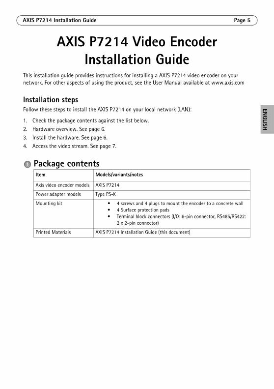
Package contentsItem Models/variants/notes
Axis video encoder models AXIS P7214
Power adapter models Type PS-K
Mounting kit • 4 screws and 4 plugs to mount the encoder to a concrete wall• 4 Surface protection pads• Terminal block connectors (I/O: 6-pin connector, RS485/RS422:
2 x 2-pin connector)
Printed Materials AXIS P7214 Installation Guide (this document)
Page 6 AXIS P7214 Installation Guide
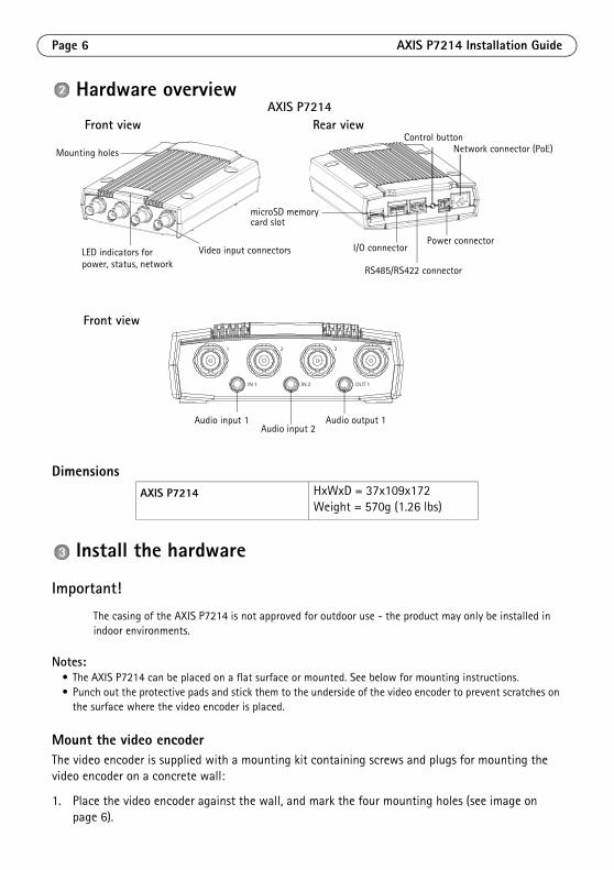
Hardware overview
Dimensions
Install the hardware
Important!
The casing of the AXIS P7214 is not approved for outdoor use - the product may only be installed in indoor environments.
Notes:• The AXIS P7214 can be placed on a flat surface or mounted. See below for mounting instructions.• Punch out the protective pads and stick them to the underside of the video encoder to prevent scratches on
the surface where the video encoder is placed.
Mount the video encoderThe video encoder is supplied with a mounting kit containing screws and plugs for mounting the video encoder on a concrete wall:
1. Place the video encoder against the wall, and mark the four mounting holes (see image on page 6).
AXIS P7214 HxWxD = 37x109x172Weight = 570g (1.26 lbs)
Mounting holes
power, status, networkLED indicators for
Power connector
RS485/RS422 connector
Network connector (PoE)Control button
I/O connector
microSD memorycard slot
Video input connectors
Front view Rear view
2 3 41
IN 1 IN 2 OUT 1
Audio input 1 Audio output 1Audio input 2
Front view
AXIS P7214
AXIS P7214 Installation Guide Page 7
ENGLISH
2. Drill the four mounting holes.3. Insert the provided wall plugs into the wall, and attach it to the wall using the screws provided.
Connect the cables1. Connect the encoder to the network using shielded network cables. If using PoE see note below.2. Optionally connect external input/output devices, e.g. alarm devices. See page 8 for information
on the terminal connector pins.3. Optionally connect active speakers and/or external microphones.
4. Connect the cameras to the video inputs.
5. If powering the unit with DC input, connect the supplied indoor power adapter or an external power supply. See note below.
6. Check that the indicator LEDs indicate the correct conditions. See the table on page 10 for further details.
Note: The unit can be powered using either the DC power input or PoE (Power over Ethernet). If powering the unit using DC power, connect the power supply to the power connector at the rear ofthe unit. If powering the unit using PoE, connect a PoE network cable.
Access the productAXIS IP Utility and AXIS Camera Management are recommended methods for finding Axis products on the network and assigning them IP addresses in Windows®. Both applications are free and can be downloaded from www.axis.com/techsup
The product can be used with most operating systems and browsers. The recommended browsers are
• Internet Explorer® with Windows®
• Safari® with OS X® and• ChromeTM or Firefox® with other operating systems.
For more information about using the product, see the User Manual available at www.axis.com
Page 8 AXIS P7214 Installation Guide
Unit connectorsNetwork connector - RJ45 Ethernet connector. Supports Power over Ethernet (PoE) Class 3 - max 12.95W. Using shielded cables is recommended.
Power input connector - 2-pin terminal block used for power input from the supplied power adapter or an external power supply.
The external power supply alternatives are:
1. The Axis delivered PS-K P/N 34987.
2. An external 8-20 V DC limited power source with a maximum output current of 5A.
Audio in/out - Two 3.5 mm jacks for audio input, and one 3.5 mm jack for audio output. Stereo plugs must be used.
• Audio Input 1, 2: Microphone or line level inputs (mono). A selectable 2.0V, 2.5V or 3.0V microphone bias is available.
• Audio Output 1: Line level audio output (mono), that can be connected to a public address (PA) system or an active speaker with a built-in amplifier.
Function Pin number Description
GND 1 Ground
DC Power 2 Power input 8-20 V DCmax 8W
Audio Input 1, Audio Input 2 Audio Output 1
1 Tip Microphone/Line in Line out (mono)
2 Ring
3 Sleeve GND GND
1 2
123
AXIS P7214 Installation Guide Page 9
ENGLISH
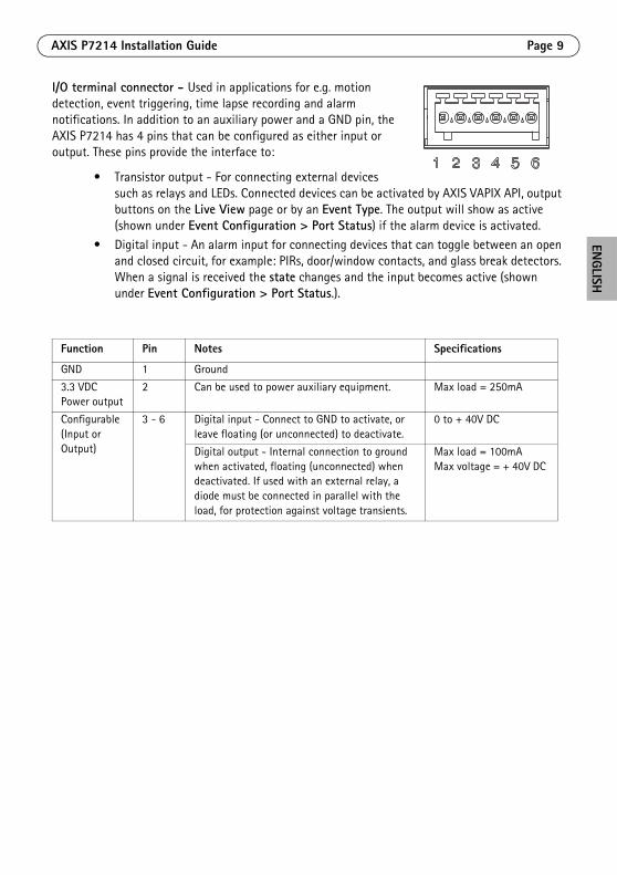
I/O terminal connector - Used in applications for e.g. motion detection, event triggering, time lapse recording and alarm notifications. In addition to an auxiliary power and a GND pin, the AXIS P7214 has 4 pins that can be configured as either input or output. These pins provide the interface to:
• Transistor output - For connecting external devices such as relays and LEDs. Connected devices can be activated by AXIS VAPIX API, output buttons on the Live View page or by an Event Type. The output will show as active (shown under Event Configuration > Port Status) if the alarm device is activated.
• Digital input - An alarm input for connecting devices that can toggle between an open and closed circuit, for example: PIRs, door/window contacts, and glass break detectors. When a signal is received the state changes and the input becomes active (shown under Event Configuration > Port Status.).
Function Pin Notes Specifications
GND 1 Ground
3.3 VDC Power output
2 Can be used to power auxiliary equipment. Max load = 250mA
Configurable (Input or Output)
3 - 6 Digital input - Connect to GND to activate, or leave floating (or unconnected) to deactivate.
0 to + 40V DC
Digital output - Internal connection to ground when activated, floating (unconnected) when deactivated. If used with an external relay, a diode must be connected in parallel with the load, for protection against voltage transients.
Max load = 100mAMax voltage = + 40V DC
Page 10 AXIS P7214 Installation Guide
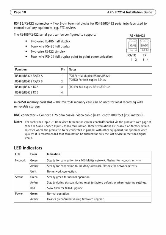
RS485/RS422 connector - Two 2-pin terminal blocks for RS485/RS422 serial interface used to control auxiliary equipment, e.g. PTZ devices.
The RS485/RS422 serial port can be configured to support:
• Two-wire RS485 half duplex• Four-wire RS485 full duplex
• Two-wire RS422 simplex
• Four-wire RS422 full duplex point to point communication
microSD memory card slot - The microSD memory card can be used for local recording with removable storage.
BNC connector - Connect a 75 ohm coaxial video cable (max. length 800 feet (250 meters)).
Note: For each video input 75 Ohm video termination can be enabled/disabled via the product's web page at Video & Audio > Video Input > Video termination. These terminations are enabled on factory default. In cases where the product is to be connected in parallel with other equipment, for optimum video quality, it is recommended that termination be enabled for only the last device in the video signal chain.
LED indicators
Function Pin Notes
RS485/RS422 RX/TX A 1 (RX) For full duplex RS485/RS422(RX/TX) For half duplex RS485RS485/RS422 RX/TX B 2
RS485/RS422 TX A 3 (TX) For full duplex RS485/RS422
RS485/RS422 TX B 4
LED Color Indication
Network Green Steady for connection to a 100 Mbit/s network. Flashes for network activity.
Amber Steady for connection to 10 Mbit/s network. Flashes for network activity.
Unlit No network connection.
Status Green Steady green for normal operation.
Amber Steady during startup, during reset to factory default or when restoring settings.
Red Slow flash for failed upgrade.
Power Green Normal operation.
Amber Flashes green/amber during firmware upgrade.
RS-485/422RS-485/422
RX/TXRX/TX1 2 3 4
TX
AXIS P7214 Installation Guide Page 11
ENGLISH
Resetting to the factory default settingsThis will reset all parameters, including the IP address, to the Factory Default settings:
1. Disconnect the power from the AXIS P7214, or if PoE is used disconnect the network cable.2. Press and hold the Control button and reconnect power or the network cable if PoE is used.
3. Keep the Control button pressed until the Status indicator displays amber (this may take up to 15 seconds).
4. Release the Control button. When the Status indicator displays green (which can take up to 1 minute) the process is complete and the video encoder has been reset.
5. Re-assign the IP address, using one of the methods described in this document.
It is also possible to reset parameters to the original factory default settings via the web interface. For more information, please see the online help or the user’s manual.
Further informationThe user’s manual is available from the Axis Web site at www.axis.com
WarrantyFor information about Axis' product warranty and thereto related information, please see www.axis.com/warranty
Tip! Visit www.axis.com/techsup to check if there is updated firmware available for your AXIS P7214. To see the currently installed firmware version, see the About web page.

Page 12 AXIS P7214 Installation Guide
FRANÇAIS
Mesures de sécuritéLisez attentivement le présent Guide d’installation avant d'installer le produit Axis. Conservez le Guide d’installation pour une utilisation ultérieure.
• Conservez le produit Axis dans un environnement sec et aéré.
• Évitez d'exposer le produit Axis aux vibrations, aux chocs ou à une forte pression. N'installez pas le produit sur un support instable, ou des surfaces ou des murs instables ou vibrants, car cela pourrait l'endommager.
• N'utilisez que les outils applicables pour installer le produit Axis ; une force excessive pourrait endommager le produit.
• Pour le nettoyage, n’utilisez ni produits chimiques, ni substances caustiques ou aérosols. Utilisez un chiffon humide pour le nettoyage.
• N’utilisez que des accessoires conformes aux caractéristiques techniques du produit. Ceux-ci peuvent être fournis par Axis ou par un fournisseur tiers.
• Utilisez uniquement des pièces de rechange fournies ou recommandées par Axis.
• Ne tentez pas de réparer le produit vous-même, contactez Axis ou votre revendeur Axis pour toute réparation.
• Ce produit Axis doit être utilisé conformément aux lois et réglementations locales en vigueur.
Transport
• Pour transporter le produit Axis et éviter de l'endommager, utilisez l'emballage d'origine ou un emballage équivalent.
Remplacement des piles Ce produit Axis nécessite une pile au lithium CR2032 de 3,0 V pour l'alimentation de son horloge en temps réel interne. Dans des conditions normales d'utilisation, cette pile est censée durer au moins 5 ans. Si la pile est faible, le fonctionnement de l'horloge en temps réel peut être affecté et entraîner sa réinitialisation à chaque mise sous tension. Un message enregistré apparaît lorsque la pile doit être remplacée. Ne remplacez la pile qu'en cas de nécessité !
Si la pile doit être remplacée, veuillez contacter www.axis.com/techsup pour obtenir de l’aide.
• Jetez les piles usagées conformément aux consignes du fabricant.
• Le remplacement incorrect de la pile peut entraîner un risque d'explosion.
• Remplacez la pile par une pile identique ou équivalente uniquement, en respectant les recommandations du fabricant.

AXIS P7214 Guide d’installation Page 15
FRANÇAIS
Encodeur vidéo AXIS P7214Guide d’installation
Ce guide d’installation vous explique comment installer un système AXIS P7214 sur votre réseau. u. Pour toute autre information relative à l’utilisation du produit, consultez le manuel de l’utilisateur disponible sur le site www.axis.com
Procédure d’installationProcédez comme suit pour installer l’AXIS P7214 sur votre réseau local :
1. Vérifiez le contenu de l’emballage par rapport à la liste ci-dessous.
2. Description du matériel. Reportez-vous à la page 16.
3. Installation du matériel. Reportez-vous à la page 17.4. Accéder au flux vidéo. Reportez-vous à la page 18
Contenu de l’emballageÉlément Modèles/variantes/remarques
Modèles d’encodeur vidéo Axis
AXIS P7214
Modèles d’adaptateur secteur
Type PS-K
Kit de montage • 4 vis et 4 chevilles pour monter l’encodeur sur un mur en béton• 4 patins de protection de surface• Connecteurs pour terminaux (E/S : connecteur à 6 broches,
RS485/422 : connecteur 2x 2 broches, alimentation : connecteur à 2 broches)
Documentation imprimée Guide d’installation AXIS P7214 (le présent document)
Important ! Ce produit doit être utilisé conformément aux lois et réglementations locales en vigueur.
Page 16 AXIS P7214 Guide d’installation
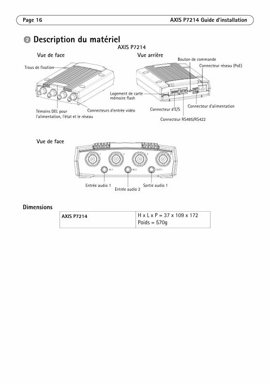
Description du matériel
DimensionsAXIS P7214 H x L x P = 37 x 109 x 172
Poids = 570g
Trous de fixation
l’alimentation, l’état et le réseauTémoins DEL pour
Connecteur d’alimentation
Connecteur RS485/RS422
Connecteur réseau (PoE)Bouton de commande
Connecteur d’E/S
Logement de carte mémoire flash
Connecteurs d’entrée vidéo
Vue de face Vue arrière
2 3 41
IN 1 IN 2 OUT 1
Entrée audio 1 Sortie audio 1Entrée audio 2
Vue de face
AXIS P7214
AXIS P7214 Guide d’installation Page 17
FRANÇAIS
Installation du matériel
Important !
Le boîtier du système AXIS P7214 n’est pas approuvé pour une utilisation à l’extérieur ; le produit doit être uniquement installé en intérieur.
Remarques :• Le système AXIS P7214 peut être placé sur une surface plane ou il peut être monté. Reportez-vous aux
instructions de montage ci-dessous.• Sortez les patins de protection de leur emballage et collez-les sur le dessous de l’encodeur vidéo pour éviter
de rayer la surface sur laquelle l’encodeur vidéo est placé.
Montage de l’encodeur vidéoL’encodeur vidéo est fourni avec un kit de montage contenant des vis et des chevilles pour la fixation de l’encodeur vidéo sur un mur en béton :
1. Placez l’encodeur vidéo contre le mur et marquez l’emplacement des quatre trous de fixation (voir l’image à la page 16).
2. Percez les quatre trous de fixation.3. Insérez les chevilles fournies dans le mur et fixez-les au mur à l’aide des vis fournies.
Branchement des câbles1. Branchez l’encodeur au réseau à l’aide des câbles réseau blindés. En cas d’utilisation du PoE,
voir la remarque ci-dessous.
2. Si vous le souhaitez, connectez des périphériques d’entrée/sortie externes, tels que des systèmes d’alarme. Reportez-vous à la page 19 pour plus d’informations sur les broches du connecteur pour terminaux.
3. Si vous le souhaitez, vous pouvez brancher des haut-parleurs actifs et/ou des microphones externes.
4. Connectez la caméra aux entrées vidéo.
5. Si l’appareil est alimenté avec une entrée en CC, branchez l’adaptateur secteur d’intérieur fourni ou une alimentation externe. Voir la remarque ci-dessous.
6. Vérifiez que les témoins DEL indiquent les bonnes conditions. Pour plus d’informations, reportez-vous au tableau de la page 22.
Note: L’appareil peut être alimenté à l’aide d’une alimentation en courant continu ou d’un PoE. Si l’appareil est alimenté par une alimentation en courant continu, branchez l’alimentation auconnecteur d’alimentation situé à l’arrière de l’appareil. Si l’appareil est alimenté par PoE, branchez un câble réseau PoE.
Page 18 AXIS P7214 Guide d’installation
Utilisez le produitSi vous souhaitez rechercher des produits Axis sur le réseau ou leur affecter des adresses IP sous Windows®, nous recommandons l’utilisation des applications AXIS IP Utility et AXIS Camera Management. Ces deux applications sont gratuites et peuvent être téléchargées depuis www.axis.com/techsup
Le produit peut être utilisé avec la plupart des systèmes d’exploitation et des navigateurs. Les navigateurs recommandés sont
• Internet Explorer® avec Windows®
• Safari® avec OS X® et
• ChromeTM ou Firefox® avec les autres systèmes d'exploitation.Pour plus d’informations concernant l’utilisation du produit, consultez le manuel de l’utilisateur disponible sur le site www.axis.com
AXIS P7214 Guide d’installation Page 19
FRANÇAIS
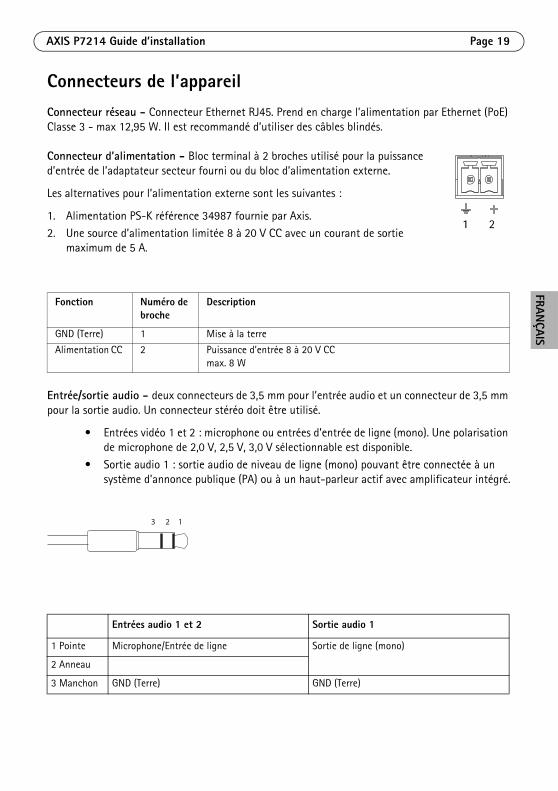
Connecteurs de l’appareilConnecteur réseau - Connecteur Ethernet RJ45. Prend en charge l’alimentation par Ethernet (PoE) Classe 3 - max 12,95 W. Il est recommandé d’utiliser des câbles blindés.
Connecteur d’alimentation - Bloc terminal à 2 broches utilisé pour la puissance d’entrée de l’adaptateur secteur fourni ou du bloc d’alimentation externe.
Les alternatives pour l’alimentation externe sont les suivantes :
1. Alimentation PS-K référence 34987 fournie par Axis.
2. Une source d’alimentation limitée 8 à 20 V CC avec un courant de sortie maximum de 5 A.
Entrée/sortie audio - deux connecteurs de 3,5 mm pour l’entrée audio et un connecteur de 3,5 mm pour la sortie audio. Un connecteur stéréo doit être utilisé.
• Entrées vidéo 1 et 2 : microphone ou entrées d’entrée de ligne (mono). Une polarisation de microphone de 2,0 V, 2,5 V, 3,0 V sélectionnable est disponible.
• Sortie audio 1 : sortie audio de niveau de ligne (mono) pouvant être connectée à un système d’annonce publique (PA) ou à un haut-parleur actif avec amplificateur intégré.
Fonction Numéro de broche
Description
GND (Terre) 1 Mise à la terre
Alimentation CC 2 Puissance d’entrée 8 à 20 V CCmax. 8 W
Entrées audio 1 et 2 Sortie audio 1
1 Pointe Microphone/Entrée de ligne Sortie de ligne (mono)
2 Anneau
3 Manchon GND (Terre) GND (Terre)
1 2
123
Page 20 AXIS P7214 Guide d’installation
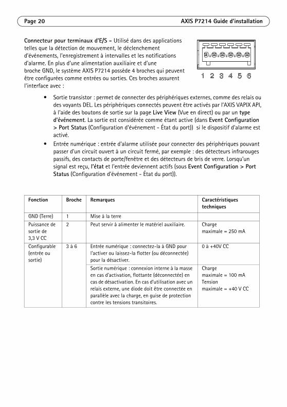
Connecteur pour terminaux d’E/S - Utilisé dans des applications telles que la détection de mouvement, le déclenchement d’événements, l’enregistrement à intervalles et les notifications d’alarme. En plus d’une alimentation auxiliaire et d’une broche GND, le système AXIS P7214 possède 4 broches qui peuvent être configurées comme entrées ou sorties. Ces broches assurent l’interface avec :
• Sortie transistor : permet de connecter des périphériques externes, comme des relais ou des voyants DEL. Les périphériques connectés peuvent être activés par l’AXIS VAPIX API, à l’aide des boutons de sortie sur la page Live View (Vue en direct) ou par un type d’événement. La sortie est considérée comme étant active (dans Event Configuration > Port Status (Configuration d’événement - État du port)) si le dispositif d’alarme est activé.
• Entrée numérique : entrée d’alarme utilisée pour connecter des périphériques pouvant passer d’un circuit ouvert à un circuit fermé, par exemple : des détecteurs infrarouges passifs, des contacts de porte/fenêtre et des détecteurs de bris de verre. Lorsqu’un signal est reçu, l’état et l’entrée deviennent actifs (sous Event Configuration > Port Status (Configuration d’événement - État du port)).
Fonction Broche Remarques Caractéristiques techniques
GND (Terre) 1 Mise à la terre
Puissance de sortie de 3,3 V CC
2 Peut servir à alimenter le matériel auxiliaire. Charge maximale = 250 mA
Configurable (entrée ou sortie)
3 à 6 Entrée numérique : connectez-la à GND pour l’activer ou laissez-la flotter (ou déconnectée) pour la désactiver.
0 à +40V CC
Sortie numérique : connexion interne à la masse en cas d’activation, flottante (déconnectée) en cas de désactivation. En cas d’utilisation avec un relais externe, une diode doit être connectée en parallèle avec la charge, en guise de protection contre les tensions transitoires.
Charge maximale = 100 mATension maximale = +40 V CC
AXIS P7214 Guide d’installation Page 21
FRANÇAIS
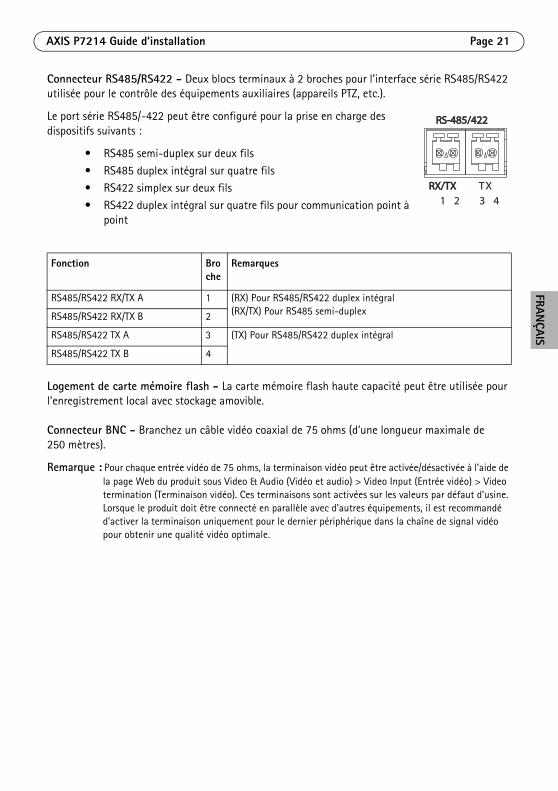
Connecteur RS485/RS422 - Deux blocs terminaux à 2 broches pour l’interface série RS485/RS422 utilisée pour le contrôle des équipements auxiliaires (appareils PTZ, etc.).
Le port série RS485/-422 peut être configuré pour la prise en charge des dispositifs suivants :
• RS485 semi-duplex sur deux fils
• RS485 duplex intégral sur quatre fils• RS422 simplex sur deux fils
• RS422 duplex intégral sur quatre fils pour communication point à point
Logement de carte mémoire flash - La carte mémoire flash haute capacité peut être utilisée pour l’enregistrement local avec stockage amovible.
Connecteur BNC - Branchez un câble vidéo coaxial de 75 ohms (d’une longueur maximale de 250 mètres).
Remarque : Pour chaque entrée vidéo de 75 ohms, la terminaison vidéo peut être activée/désactivée à l’aide de la page Web du produit sous Video & Audio (Vidéo et audio) > Video Input (Entrée vidéo) > Video termination (Terminaison vidéo). Ces terminaisons sont activées sur les valeurs par défaut d’usine. Lorsque le produit doit être connecté en parallèle avec d’autres équipements, il est recommandé d’activer la terminaison uniquement pour le dernier périphérique dans la chaîne de signal vidéo pour obtenir une qualité vidéo optimale.
Fonction Broche
Remarques
RS485/RS422 RX/TX A 1 (RX) Pour RS485/RS422 duplex intégral(RX/TX) Pour RS485 semi-duplexRS485/RS422 RX/TX B 2
RS485/RS422 TX A 3 (TX) Pour RS485/RS422 duplex intégral
RS485/RS422 TX B 4
RS-485/422RS-485/422
RX/TXRX/TX1 2 3 4
TX
Page 22 AXIS P7214 Guide d’installation
Témoins DELVoyant DEL
Couleur Indication
Réseau Vert Continu en cas de connexion à un réseau de 100 Mbit/s. Clignote en cas d’activité réseau.
Orange Continu en cas de connexion à un réseau de 10 Mbit/s. Clignote en cas d’activité réseau.
Éteint Pas de connexion réseau.
État Vert Vert continu en cas de fonctionnement normal.
Orange En continu pendant le démarrage, la réinitialisation des paramètres d’usine par défaut ou la restauration des paramètres.
Rouge Clignotement lent en cas d’échec de la mise à niveau.
Alimenta-tion
Vert Fonctionnement normal.
Orange Clignote en vert/orange pendant la mise à niveau des micrologiciels.
AXIS P7214 Guide d’installation Page 23
FRANÇAIS
Rétablissement des paramètres d’usine par défautProcédez comme suit pour rétablir tous les paramètres d’usine par défaut, y compris l’adresse IP :
1. Mettez le système AXIS P7214 hors tension ou, si vous utilisez la PoE, débranchez le câble réseau.
2. Appuyez sur le bouton de commande et maintenez-le enfoncé tout en remettant l’appareil sous tension ou en rebranchant le câble réseau si vous utilisez la PoE.
3. Appuyez sur le bouton de commande jusqu’à ce que le voyant d’état passe à l’orange (cela peut prendre jusqu’à 15 secondes).
4. Relâchez le bouton de commande. Lorsque le voyant d’état émet une lumière verte (ce qui peut prendre 1 minute), le processus est terminé et les paramètres par défaut de l’encodeur vidéo ont été rétablis.
5. Attribuez à nouveau l’adresse IP à l’aide de l’une des méthodes décrites dans ce document.
Il est également possible de rétablir les paramètres d’usine par défaut à partir de l’interface Web. Pour obtenir plus d’informations, reportez-vous à l’aide en ligne ou au manuel d’utilisation.
Informations complémentairesLe manuel de l’utilisateur est disponible sur le site Web d’Axis (www.axis.com)
GarantiePour plus d'informations sur la garantie des produits Axis et des informations générales relatives à celle-ci merci de consulter le site www.axis.com/warranty
Conseil : Consultez le site www.axis.com/techsup pour vérifier si des mises à jour de micrologiciels sont disponibles pour votre système AXIS P7214. Pour connaître la version de micrologiciel actuellement installée, reportez-vous à la page Web About (À propos de).

Page 24 AXIS P7214 Guide d’installation
DEUTSCH
SicherheitsvorkehrungenBitte lesen Sie diese Installationsanleitung sorgfältig durch, bevor Sie mit der Installation des Axis Produkts beginnen. Halten Sie die Installationsanleitung bereit, falls Sie darauf zurückgreifen müssen.
• Lagern Sie das Axis-Produkt in einer trockenen und belüfteten Umgebung.• Setzen Sie das Axis Produkt keinen Vibrationen, Erschütterungen oder starkem Druck aus.
Installieren Sie das Produkt nicht an instabilen Halterungen oder instabilen oder vibrierenden Oberflächen oder Mauern, da dadurch das Produkt beschädigt werden könnte.
• Verwenden Sie bei der Installation des Axis Produkts nur geeignetes Werkzeug; zu hoher Kraftaufwand kann das Produkt beschädigen.
• Verwenden Sie keine chemischen, ätzenden oder aerosolhaltigen Reinigungsmittel. Verwenden Sie zur Reinigung ein feuchtes Tuch.
• Verwenden Sie nur Zubehör, das den technischen Spezifikationen des Produkts entspricht. Dieses ist von Axis oder Drittanbietern erhältlich.
• Verwenden Sie nur Ersatzteile, die von Axis empfohlen bzw. bereitgestellt wurden.• Versuchen Sie nicht, das Produkt selbst zu reparieren. Wenden Sie sich bei Service-
Angelegenheiten an Axis oder an Ihren Axis-Händler.
• Verwenden Sie dieses Axis-Produkt unter Beachtung der vor Ort geltenden rechtlichen Bestimmungen.
Transport
• Transportieren Sie das Axis-Produkt nur in der Originalverpackung bzw. in einer vergleichbaren Verpackung, damit das Produkt nicht beschädigt wird.
Batteriewechsel Dieses Axis-Produkt ist mit einer 3,0 V CR2032 Lithium-Batterie als Stromversorgung für die interne Echtzeituhr (RTC) ausgestattet. Unter normalen Bedingungen hält die Batterie mindestens 5 Jahre. Bei entladener Batterie ist der Betrieb der Echtzeituhr nicht mehr ausreichend gewährleistet, so dass die Uhr bei jedem Systemstart zurückgesetzt wird. Sie erhalten eine Protokollnachricht, wenn ein Batteriewechsel erforderlich ist. Die Batterie sollte erst bei Bedarf gewechselt werden.
Unter www.axis.com/techsup finden Sie Informationen darüber, was Sie beim Austausch der Batterie beachten müssen.
• Verbrauchte Batterien sind gemäß den Herstelleranweisungen zu entsorgen.
• Explosionsgefahr bei fehlerhaftem Batteriewechsel!• Die Batterie muss durch dasselbe oder ein gleichwertiges Fabrikat ersetzt werden, das vom
Hersteller zugelassen ist.

AXIS P7214 Installationsanleitung Seite 27
DEUTSCH
AXIS P7214 Video-Encoder Installationsanleitung
In dieser Anleitung wird die Installation eines AXIS P7214 in einem Netzwerk beschrieben. Weitere Informationen zur Nutzung dieses Produkts finden Sie im Benutzerhandbuch unter www.axis.com.
InstallationsschritteFühren Sie die folgenden Schritte aus, um die AXIS P7214 in Ihrem lokalen Netzwerk (LAN) zu installieren:
1. Prüfen Sie, ob alle in der nachfolgenden Liste aufgeführten Komponenten vorhanden sind.
2. Sehen Sie sich die Hardwareübersicht an. Siehe Seite 28.
3. Installieren Sie die Hardware. Siehe Seite 29.4. Zugriff auf den Video Stream. Siehe Seite 30.
LieferumfangKomponente Modelle/Varianten/Anmerkungen
Axis Video-Encoder-Modell AXIS P7214
Netzteilmodelle Typ PS-K
Montagesatz • 4 Schrauben und Dübel zur Montage des Encoders an einer Betonwand
• 4 Klebeschutzfüße• Anschlussverteiler (E/A: 6-poliger Anschluss für die RS485/422-
Verbindung 2x 2-poliger Anschluss, Netz: 2-poliger Anschluss)
Gedruckte Dokumente AXIS P7214 Installationsanleitung (dieses Dokument)
Seite 28 AXIS P7214 Installationsanleitung
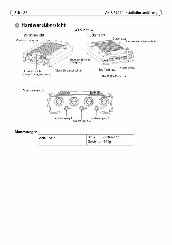
Hardwareübersicht
AbmessungenAXIS P7214 HxBxT = 37x109x172
Gewicht = 570g
Montagebohrungen
Strom, Status, NetzwerkLED-Anzeigen für
Netzanschluss
RS485/RS422-Buchse
Steuertaste
E/A-Anschluss
microSD-SpeicherSteckplatz
Video-Eingangsbuchsen
Vorderansicht Rückansicht
Netzwerkanschluss (mit PoE
2 3 41
IN 1 IN 2 OUT 1
Audioeingang 1 Audioausgang 1Audioeingang 2
Vorderansicht
AXIS P7214
AXIS P7214 Installationsanleitung Seite 29
DEUTSCH
Installation der Hardware
Wichtig!
Das Gehäuse der AXIS P7214 ist nicht für den Einsatz im Aussenbereich geeignet – das Produkt sollte nur in Innenbereichen installiert werden.
Hinweise:• Sie können den Video-Encoder AXIS P7214 einfach auf einer ebenen Fläche positionieren oder montieren.
Bitte beachten Sie die nachstehenden Montageanweisungen.• Drücken Sie die vier Schutzfüße heraus und kleben Sie sie auf die Unterseite des Video-Encoders, um die
Aufstellfläche vor Kratzern zu schützen.
Befestigen Sie den Video-EncoderDer Video-Encoder wird mit einem Montagesatz mit Schrauben und Dübeln geliefert, um den Video-Encoder an einer Betonwand zu befestigen:
1. Halten Sie den Video-Encoder in der gewünschten Position an die Wand und markieren Sie die vier Montagelöcher (siehe Abbildung auf Seite 28).
2. Bohren Sie die Montagelöcher in die Wand.3. Drücken Sie die Wanddübel in die Löcher und befestigen Sie sie mit den mitgelieferten
Schrauben.
Schließen Sie die Kabel an1. Verbinden Sie den Encoder über ein abgeschirmtes Netzwerkkabel mit dem Netzwerk. Bei der
Verwendung von PoE bitte den Hinweis unten beachten.
2. Sie können zusätzlich externe E/A-Geräte, wie z. B. Alarmanlagen, anschließen. Informationen zur Anschlussbelegung finden Sie auf Seite 31.
3. Sie können zusätzlich einen Aktivlautsprecher und/oder ein externes Mikrofon anschließen.
4. Schließen Sie die Kameras an die Videoeingänge an.5. Wenn die Stromversorgung des Geräts über den Netzeingang mit Gleichstrom erfolgt, schließen
Sie das Netzteil für geschlossene Räume oder ein externes Netzteil an. Bitte beachten Sie den Hinweis unten.
6. Überprüfen Sie, ob die LED-Anzeigen die Betriebszustände korrekt angeben. Weitere Informationen hierzu finden Sie in der Tabelle auf Seite 34.
Hinweis: Die Stromversorgung des Geräts kann entweder über den Netzeingang mit Gleichstrom oder über PoE (Power over Ethernet) erfolgen. Bei der Stromversorgung des Geräts mit Gleichstrom schließen Sie das Netzteil an den Stromversorgungsanschluss an der Geräterückseite an. Bei der Stromversorgung des Geräts mit PoE (Power over Ethernet) schließen Sie ein PoENetzwerkkabel an.
Seite 30 AXIS P7214 Installationsanleitung
Zugriff auf das ProduktFür die Suche nach Axis Produkten im Netzwerk und zur Zuweisung einer IP-Adresse unter Windows® werden AXIS IP Utility und AXIS Camera Management empfohlen. Beide Anwendungen sind kostenlos und können von unserer Website unter www.axis.com/techsup heruntergeladen werden.
Das Produkt ist mit den meisten Standard-Betriebssystemen und Browsern kompatibel. Empfohlen werden die Browser
• Internet Explorer® unter Windows®
• Safari® unter OS X® und
• ChromeTM oder Firefox® unter anderen Betriebssystemen.Weitere Informationen zur Nutzung dieses Produkts finden Sie im Benutzerhandbuch unter www.axis.com.
AXIS P7214 Installationsanleitung Seite 31
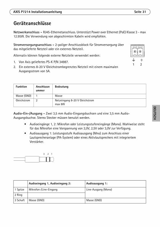
DEUTSCH
GeräteanschlüsseNetzwerkanschluss - RJ45-Ethernetanschluss. Unterstüzt Power over Ethernet (PoE) Klasse 3 - max 12.95W. Die Verwendung von abgeschirmten Kabeln wird empfohlen.
Stromversorgungsanschluss - 2-poliger Anschlussblock für Stromversorgung über das mitgelieferte Netzteil oder ein externes Netzteil.
Alternativ können folgende externe Netzteile verwendet werden:
1. Von Axis geliefertes PS-K P/N 34987.
2. Ein externes 8-20 V Gleichstrombegrenztes Netzteil mit einem maximalen Ausgangsstrom von 5A.
Audio-Ein-/Ausgang - Zwei 3,5 mm Audio-Eingangsbuchsen und eine 3,5 mm Audio-Ausgangsbuchse. Stereo Stecker müssen benutzt werden.
• Audioeingänge 1, 2: Mikrofon oder Leistungsstufeneingänge (Mono). Wahlweise steht für das Mikrofon eine Vorspannung von 2,0V, 2,5V oder 3,0V zur Verfügung.
• Audioausgang 1: Leistungsstufe Audioausgang (Mno) zum Anschluss einer Lautsprecheranlage (PA-System) oder eines Aktivlautsprechers mit integriertem Verstärker.
Funktion Anschlussnummer
Bedeutung
Masse (GND) 1 Masse
Gleichstrom 2 Netzeingang 8-20 V Gleichstrommax 8W
Audioeingang 1, Audioeingang 2: Audioausgang 1:
1 Spitze Mikrofon-/Line-Eingang Line-Ausgang (Mono)
2 Ring
3 Schaft Masse (GND) Masse (GND)
1 2
123
Seite 32 AXIS P7214 Installationsanleitung
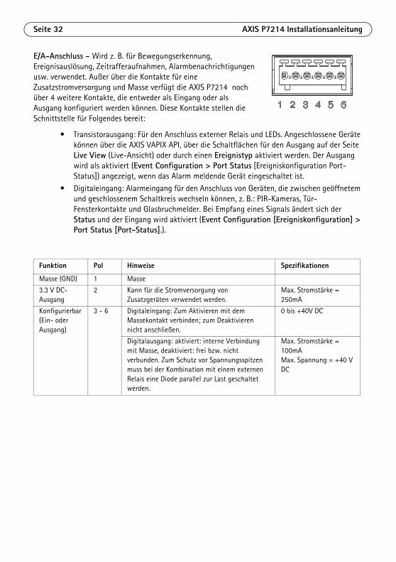
E/A-Anschluss - Wird z. B. für Bewegungserkennung, Ereignisauslösung, Zeitrafferaufnahmen, Alarmbenachrichtigungen usw. verwendet. Außer über die Kontakte für eine Zusatzstromversorgung und Masse verfügt die AXIS P7214 noch über 4 weitere Kontakte, die entweder als Eingang oder als Ausgang konfiguriert werden können. Diese Kontakte stellen die Schnittstelle für Folgendes bereit:
• Transistorausgang: Für den Anschluss externer Relais und LEDs. Angeschlossene Geräte können über die AXIS VAPIX API, über die Schaltflächen für den Ausgang auf der Seite Live View (Live-Ansicht) oder durch einen Ereignistyp aktiviert werden. Der Ausgang wird als aktiviert (Event Configuration > Port Status [Ereigniskonfiguration Port-Status]) angezeigt, wenn das Alarm meldende Gerät eingeschaltet ist.
• Digitaleingang: Alarmeingang für den Anschluss von Geräten, die zwischen geöffnetem und geschlossenem Schaltkreis wechseln können, z. B.: PIR-Kameras, Tür-Fensterkontakte und Glasbruchmelder. Bei Empfang eines Signals ändert sich der Status und der Eingang wird aktiviert (Event Configuration [Ereigniskonfiguration] > Port Status [Port-Status].).
Funktion Pol Hinweise Spezifikationen
Masse (GND) 1 Masse
3.3 V DC-Ausgang
2 Kann für die Stromversorgung von Zusatzgeräten verwendet werden.
Max. Stromstärke = 250mA
Konfigurierbar (Ein- oder Ausgang)
3 - 6 Digitaleingang: Zum Aktivieren mit dem Massekontakt verbinden; zum Deaktivieren nicht anschließen.
0 bis +40V DC
Digitalausgang: aktiviert: interne Verbindung mit Masse, deaktiviert: frei bzw. nicht verbunden. Zum Schutz vor Spannungsspitzen muss bei der Kombination mit einem externen Relais eine Diode parallel zur Last geschaltet werden.
Max. Stromstärke = 100mAMax. Spannung = +40 V DC
AXIS P7214 Installationsanleitung Seite 33
DEUTSCH
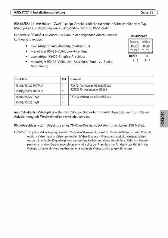
RS485/RS422-Anschluss - Zwei 2-polige Anschlussblöcke für serielle Schnittstellen vom Typ RS485/-422 zur Steuerung von Zusatzgeräten, wie z. B. PTZ-Geräten.
Der serielle RS485/-422-Anschluss kann in den folgenden Anschlussmodi konfiguriert werden:
• zweiadriger RS485-Halbduplex-Anschluss
• vieradriger RS485-Vollduplex-Anschluss• zweiadriger RS422-Simplex-Anschluss
• vieradriger RS422-Vollduplex-Anschluss (Punkt-zu-Punkt-Verbindung)
microSD-Karten-Steckplatz - Die microSD-Speicherkarte mit hoher Kapazität kann zur lokalen Aufzeichnung mit Wechselmedien verwendet werden.
BNC-Anschluss - Zum Anschluss eines 75-Ohm-Koaxialvideokabels (max. Länge 250 Meter).
Hinweis: Für jeden Videoeingang kann der 75-Ohm-Videoanschluss auf der Produkt-Webseite unter Video & Audio > Video Input > Video termination (Video-Eingang - Videoanschluss) aktiviert/deaktiviert werden. Standardmäßig erfolgt eine werkseitige Aktivierung dieser Anschlüsse. Falls das Produkt parallel an andere Geräte angeschlossen wird, sollte der Anschluss nur für das letzte Gerät in der Videosignalkette aktiviert werden, um eine optimale Videoqualität zu gewährleisten.
Funktion Pol Hinweise
RS485/RS422 RX/TX A 1 (RX) Für Vollduplex RS485/RS422(RX/TX) Für Halbduplex RS485RS485/RS422 RX/TX B 2
RS485/RS422 TX/A 3 (TX) Für Vollduplex RS485/RS422
RS485/RS422 TX/B 4
RS-485/422RS-485/422
RX/TXRX/TX1 2 3 4
TX
Seite 34 AXIS P7214 Installationsanleitung
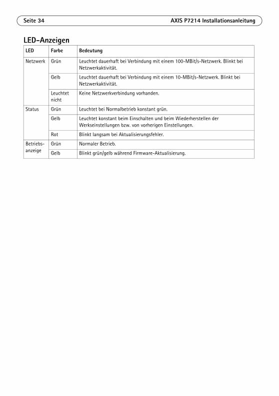
LED-AnzeigenLED Farbe Bedeutung
Netzwerk Grün Leuchtet dauerhaft bei Verbindung mit einem 100-MBit/s-Netzwerk. Blinkt bei Netzwerkaktivität.
Gelb Leuchtet dauerhaft bei Verbindung mit einem 10-MBit/s-Netzwerk. Blinkt bei Netzwerkaktivität.
Leuchtet nicht
Keine Netzwerkverbindung vorhanden.
Status Grün Leuchtet bei Normalbetrieb konstant grün.
Gelb Leuchtet konstant beim Einschalten und beim Wiederherstellen der Werkseinstellungen bzw. von vorherigen Einstellungen.
Rot Blinkt langsam bei Aktualisierungsfehler.
Betriebs-anzeige
Grün Normaler Betrieb.
Gelb Blinkt grün/gelb während Firmware-Aktualisierung.
AXIS P7214 Installationsanleitung Seite 35
DEUTSCH
Wiederherstellen der werkseitigen StandardeinstellungenGehen Sie wie folgt vor, um sämtliche Parameter einschließlich der IP-Adresse auf die werkseitigen Standardeinstellungen zurückzusetzen:
1. Trennen Sie die AXIS P7214 von der Stromversorgung oder ziehen Sie, falls PoE verwendet wird, das Netzwerkkabel ab.
2. Halten Sie die Steuertaste gedrückt und schließen Sie das Netzkabel oder bei Verwendung von PoE das Netzwerkkabel wieder an.
3. Halten Sie die Steuertaste so lange gedrückt, bis die Statusanzeige gelb aufleuchtet (dies kann bis zu 15 Sekunden dauern).
4. Lassen Sie die Steuertaste los. Sobald die Statusanzeige grün leuchtet (dies kann bis zu einer Minute dauern), ist der Video-Encoder auf die werkseitigen Standardeinstellungen zurückgesetzt.
5. Legen Sie die IP-Adresse erneut fest. Wenden Sie dabei eines der in diesem Handbuch beschriebenen Verfahren an.
Die Parameter können auch über die Weboberfläche auf die werkseitigen Einstellungen zurückgesetzt werden. Weitere Informationen dazu finden Sie in der Online-Hilfe und im Benutzerhandbuch.
Weitere InformationenDas Benutzerhandbuch ist auf der Axis Website unter „http://www.axis.com“
GarantieDie Garantiebedingungen für Axis Produkte sowie weitere Informationen zum Thema Garantie finden Sie unter www.axis.com/warranty
Tipp! Unter www.axis.com/techsup finden Sie Firmware-Aktualisierungen für Ihre AXIS P7214. Information zur aktuellen Firmware-Version finden Sie auf der Webseite About.

Seite 36 AXIS P7214 Installationsanleitung
ITALIANO
SicurezzaLeggere attentamente questa Guida all'installazione prima di installare un prodotto Axis. Conservare la Guida all'installazione per ulteriori riferimenti.
• Conservare il prodotto Axis in un ambiente asciutto e ben ventilato.
• Evitare di esporre il prodotto Axis alle vibrazioni, agli urti o a forte pressione. Non installare il prodotto su staffe instabili, superfici o pareti instabili o vibranti, poiché ciò potrebbe danneggiare il prodotto.
• Utilizzare solo strumenti idonei quando si installa il prodotto Axis. Una forza eccessiva potrebbe danneggiare il prodotto.
• Non utilizzare sostanze chimiche, agenti caustici o detergenti spray. Utilizzare un panno umido per la pulizia.
• Utilizzare solo accessori conformi con le specifiche tecniche del prodotto. Queste possono essere fornite da Axis o da terze parti.
• Utilizzare solo parti di ricambio fornite o raccomandate da Axis.
• Non tentare di riparare il prodotto da soli, contattare Axis o il rivenditore di zona Axis per assistenza.
• Questo prodotto Axis deve essere utilizzato in conformità alle leggi e alle disposizioni locali.
Trasporto
• Quando si trasporta il prodotto Axis, utilizzare l'imballo originale o un imballo equivalente per evitare di danneggiare il prodotto.
Sostituzione della batteriaQuesto prodotto Axis utilizza una batteria al litio CR2032 da 3.0 V per alimentare il real-time clock (RTC) interno. In normali condizioni questa batteria ha una durata di almeno 5 anni. La batteria scarica influisce sul funzionamento dell'RTC, che viene reimpostato ad ogni accensione. Un messaggio di registro apparirà quando la batteria dovrà essere sostituita. La batteria non deve essere sostituita a meno che non sia necessario.
Se la batteria non deve essere sostituita, contattare www.axis.com/techsup per assistenza.
• Smaltire le batterie usate secondo le istruzioni del produttore.
• Rischio di esplosione se la batteria non viene sostituita correttamente.
• Sostituire solo con una batteria identica o equivalente, come raccomandato dal produttore.

Guida all'installazione di AXIS P7214 Pagina 39
ITALIANO
AXIS P7214 Codificatore videoGuida all'installazione
Questo documento fornisce le istruzioni necessarie per installare il codificatore video AXIS P7214 nella rete in uso. Per ulteriori informazioni sull'utilizzo del dispositivo, consultare la Guida per l'utente disponibile all'indirizzo www.axis.com
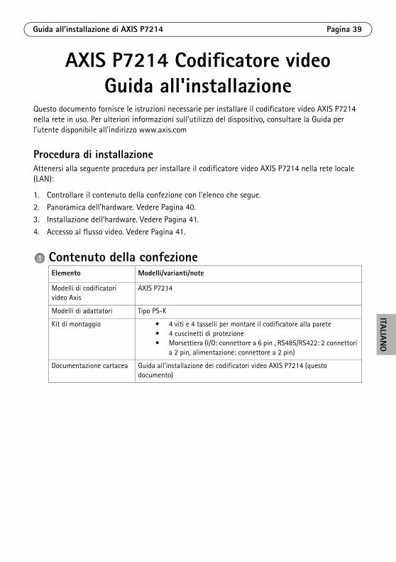
Procedura di installazioneAttenersi alla seguente procedura per installare il codificatore video AXIS P7214 nella rete locale (LAN):
1. Controllare il contenuto della confezione con l'elenco che segue.2. Panoramica dell’hardware. Vedere Pagina 40.
3. Installazione dell’hardware. Vedere Pagina 41.
4. Accesso al flusso video. Vedere Pagina 41.
Contenuto della confezioneElemento Modelli/varianti/note
Modelli di codificatori video Axis
AXIS P7214
Modelli di adattatori Tipo PS-K
Kit di montaggio • 4 viti e 4 tasselli per montare il codificatore alla parete• 4 cuscinetti di protezione• Morsettiera (I/O: connettore a 6 pin , RS485/RS422: 2 connettori
a 2 pin, alimentazione: connettore a 2 pin)
Documentazione cartacea Guida all'installazione dei codificatori video AXIS P7214 (questo documento)
Pagina 40 Guida all'installazione di AXIS P7214
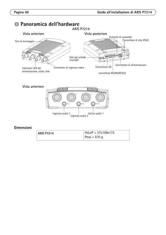
Panoramica dell’hardware
DimensioniAXIS P7214 HxLxP = 37x109x172
Peso = 570 g
Fori di montaggio
alimentazione, stato, reteIndicatori LED del
Connettore di alimentazione
connettore RS485/RS422
Connettore di rete (PoE)Pulsante di comando
Connettore I/O
Slot per schedamicroSD
Connettori di ingresso video
Vista anteriore Vista posteriore
2 3 41
IN 1 IN 2 OUT 1
Ingresso audio 1 Uscita audio 1Ingresso audio 2
Vista anteriore
AXIS P7214
Guida all'installazione di AXIS P7214 Pagina 41
ITALIANO
Installazione dell'hardware
Importante!
L'alloggiamento del codificatore video AXIS P7214 non è approvato l'utilizzo in ambienti esterni. Il prodotto può essere installato soltanto in ambienti interni.
Note:• Il codificatore video AXIS P7214 può essere semplicemente posizionato o montato su una superficie piana.
Fare riferimento alle seguenti sezioni per le istruzioni di montaggio.• Punzonare i cuscinetti di protezione e applicarli alla base del codificatore video per evitare di graffiare la
superficie al momento del posizionamento del codificatore video.
Montaggio del codificatore videoIl codificatore video viene fornito con un kit di montaggio contenente viti e tasselli per il montaggio a parete:
1. Appoggiare il codificatore video contro la parete e contrassegnare la posizione dei due fori di montaggio (vedere la figura a pagina Pagina 40).
2. Realizzare i quattro fori di montaggio.3. Inserire i tasselli nella parete e fissare il codificatore video alla parete con le viti fornite.
Collegamento dei cavi1. Collegare il codificatore alla rete mediante cavi di rete schermati. Consultare le sezioni che
seguono per PoE.
2. Collegare gli altri dispositivi esterni (opzionali) come eventuali sistemi di allarme. Per informazioni sui pin della morsettiera di alimentazione, vedere la Pagina 43.
3. Collegare, facoltativamente, gli altoparlante attivi e/o i microfoni esterni.4. Collegare le telecamere agli ingressi video.
5. Se l'unità è alimentata dall'ingresso CC, collegare l'alimentatore per interni fornito in dotazione o l'alimentatore esterno. Fare riferimento alla nota seguente.
6. Verificare che i LED indichino le condizioni di funzionamento corrette. Per ulteriori dettagli, vedere la tabella a Pagina 45.
Nota: L'unità può essere alimentata tramite l'ingresso di alimentazione CC o PoE. Per alimentare l'unità tramite l'ingresso CC, collegare l'alimentatore al connettore di alimentazione sul retro dell'unità. Per alimentare l'unità tramite PoE, collegare un cavo di rete PoE.
Accedere al dispositivoAXIS IP Utility e AXIS Camera Management sono i metodi consigliati per trovare i dispositivi Axis in rete e assegnare loro un indirizzo IP in Windows®. Queste applicazioni sono entrambe gratuite e possono essere scaricate da www.axis.com/techsup
Pagina 42 Guida all'installazione di AXIS P7214
Il dispositivo può essere utilizzato con la maggior parte dei sistemi operativi e dei browser. I browser consigliati sono
• Internet Explorer® con Windows®
• Safari® con OS X® e
• ChromeTM o Firefox® con altri sistemi operativi.Per ulteriori informazioni sull'utilizzo del dispositivo, consultare la Guida per l'utente disponibile all'indirizzo www.axis.com
Guida all'installazione di AXIS P7214 Pagina 43
ITALIANO
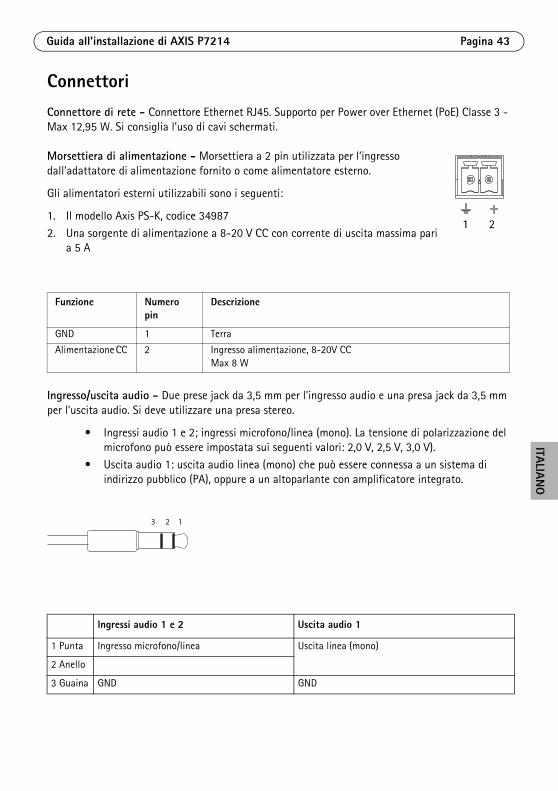
ConnettoriConnettore di rete - Connettore Ethernet RJ45. Supporto per Power over Ethernet (PoE) Classe 3 - Max 12,95 W. Si consiglia l'uso di cavi schermati.
Morsettiera di alimentazione - Morsettiera a 2 pin utilizzata per l’ingresso dall'adattatore di alimentazione fornito o come alimentatore esterno.
Gli alimentatori esterni utilizzabili sono i seguenti:
1. Il modello Axis PS-K, codice 34987
2. Una sorgente di alimentazione a 8-20 V CC con corrente di uscita massima pari a 5 A
Ingresso/uscita audio - Due prese jack da 3,5 mm per l'ingresso audio e una presa jack da 3,5 mm per l'uscita audio. Si deve utilizzare una presa stereo.
• Ingressi audio 1 e 2; ingressi microfono/linea (mono). La tensione di polarizzazione del microfono può essere impostata sui seguenti valori: 2,0 V, 2,5 V, 3,0 V).
• Uscita audio 1: uscita audio linea (mono) che può essere connessa a un sistema di indirizzo pubblico (PA), oppure a un altoparlante con amplificatore integrato.
Funzione Numero pin
Descrizione
GND 1 Terra
Alimentazione CC 2 Ingresso alimentazione, 8-20V CCMax 8 W
Ingressi audio 1 e 2 Uscita audio 1
1 Punta Ingresso microfono/linea Uscita linea (mono)
2 Anello
3 Guaina GND GND
1 2
123
Pagina 44 Guida all'installazione di AXIS P7214
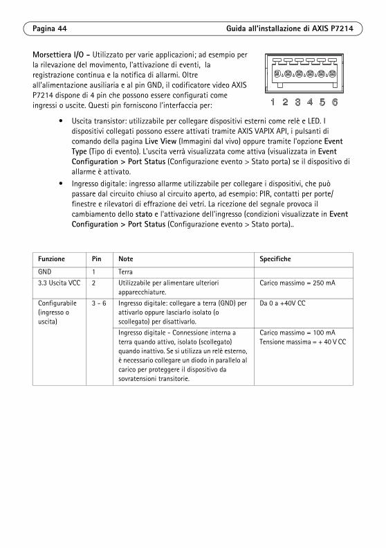
Morsettiera I/O - Utilizzato per varie applicazioni; ad esempio per la rilevazione del movimento, l'attivazione di eventi, la registrazione continua e la notifica di allarmi. Oltre all'alimentazione ausiliaria e al pin GND, il codificatore video AXIS P7214 dispone di 4 pin che possono essere configurati come ingressi o uscite. Questi pin forniscono l'interfaccia per:
• Uscita transistor: utilizzabile per collegare dispositivi esterni come relè e LED. I dispositivi collegati possono essere attivati tramite AXIS VAPIX API, i pulsanti di comando della pagina Live View (Immagini dal vivo) oppure tramite l'opzione Event Type (Tipo di evento). L'uscita verrà visualizzata come attiva (visualizzata in Event Configuration > Port Status (Configurazione evento > Stato porta) se il dispositivo di allarme è attivato.
• Ingresso digitale: ingresso allarme utilizzabile per collegare i dispositivi, che può passare dal circuito chiuso al circuito aperto, ad esempio: PIR, contatti per porte/finestre e rilevatori di effrazione dei vetri. La ricezione del segnale provoca il cambiamento dello stato e l'attivazione dell'ingresso (condizioni visualizzate in Event Configuration > Port Status (Configurazione evento > Stato porta)..
Funzione Pin Note Specifiche
GND 1 Terra
3.3 Uscita VCC 2 Utilizzabile per alimentare ulteriori apparecchiature.
Carico massimo = 250 mA
Configurabile (ingresso o uscita)
3 - 6 Ingresso digitale: collegare a terra (GND) per attivarlo oppure lasciarlo isolato (o scollegato) per disattivarlo.
Da 0 a +40V CC
Ingresso digitale - Connessione interna a terra quando attivo, isolato (scollegato) quando inattivo. Se si utilizza un relè esterno, è necessario collegare un diodo in parallelo al carico per proteggere il dispositivo da sovratensioni transitorie.
Carico massimo = 100 mATensione massima = + 40 V CC
Guida all'installazione di AXIS P7214 Pagina 45
ITALIANO
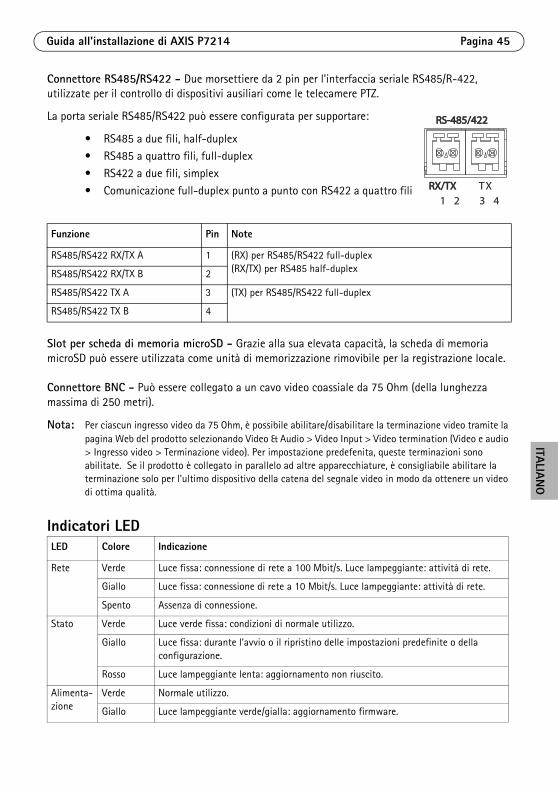
Connettore RS485/RS422 - Due morsettiere da 2 pin per l'interfaccia seriale RS485/R-422, utilizzate per il controllo di dispositivi ausiliari come le telecamere PTZ.
La porta seriale RS485/RS422 può essere configurata per supportare:
• RS485 a due fili, half-duplex• RS485 a quattro fili, full-duplex
• RS422 a due fili, simplex
• Comunicazione full-duplex punto a punto con RS422 a quattro fili
Slot per scheda di memoria microSD - Grazie alla sua elevata capacità, la scheda di memoria microSD può essere utilizzata come unità di memorizzazione rimovibile per la registrazione locale.
Connettore BNC - Può essere collegato a un cavo video coassiale da 75 Ohm (della lunghezza massima di 250 metri).
Nota: Per ciascun ingresso video da 75 Ohm, è possibile abilitare/disabilitare la terminazione video tramite la pagina Web del prodotto selezionando Video & Audio > Video Input > Video termination (Video e audio > Ingresso video > Terminazione video). Per impostazione predefenita, queste terminazioni sono abilitate. Se il prodotto è collegato in parallelo ad altre apparecchiature, è consigliabile abilitare la terminazione solo per l'ultimo dispositivo della catena del segnale video in modo da ottenere un video di ottima qualità.
Indicatori LED
Funzione Pin Note
RS485/RS422 RX/TX A 1 (RX) per RS485/RS422 full-duplex(RX/TX) per RS485 half-duplexRS485/RS422 RX/TX B 2
RS485/RS422 TX A 3 (TX) per RS485/RS422 full-duplex
RS485/RS422 TX B 4
LED Colore Indicazione
Rete Verde Luce fissa: connessione di rete a 100 Mbit/s. Luce lampeggiante: attività di rete.
Giallo Luce fissa: connessione di rete a 10 Mbit/s. Luce lampeggiante: attività di rete.
Spento Assenza di connessione.
Stato Verde Luce verde fissa: condizioni di normale utilizzo.
Giallo Luce fissa: durante l’avvio o il ripristino delle impostazioni predefinite o della configurazione.
Rosso Luce lampeggiante lenta: aggiornamento non riuscito.
Alimenta-zione
Verde Normale utilizzo.
Giallo Luce lampeggiante verde/gialla: aggiornamento firmware.
RS-485/422RS-485/422
RX/TXRX/TX1 2 3 4
TX
Pagina 46 Guida all'installazione di AXIS P7214
Ripristino delle impostazioni predefiniteQuesta procedura consente di ripristinare le impostazioni predefinite per tutti i parametri, incluso l’indirizzo IP.
1. Scollegare il codificatore video AXIS P7214 dall'alimentazione oppure scollegare il cavo di rete se si utilizza PoE.
2. Premere e tenere premuto il pulsante di comando e ricollegare l’alimentazione o il cavo di rete se si utilizza PoE.
3. Tenere premuto il pulsante di comando fino a quando l'indicatore di stato non inizia a lampeggiare in giallo (l'operazione può richiedere fino a 15 secondi).
4. Rilasciare il pulsante di comando. Appena l'indicatore di stato diventa verde (l'operazione può richiedere fino a 1 minuto), significa che la procedura è terminata e che il codificatore video è stato reimpostato.
5. Riassegnare l’indirizzo IP utilizzando uno dei metodi descritti in questo documento.
È possibile inoltre reimpostare i parametri alle impostazioni predefinite in fabbrica mediante l’interfaccia Web. Per ulteriori informazioni, consultare la Guida in linea o la Guida per l'utente.
Ulteriori informazioniLa Guida per l’utente è disponibile sul sito Web di Axis all’indirizzo www.axis.com
GaranziaPer informazioni relative alla garanzia del prodotto AXIS ed ogni altra ulteriore informazione correlata, si prega di consultare la pagina http://www.axis.com/warranty
Suggerimento Visitare il sito di Axis all’indirizzo www.axis.com/techsup per verificare se sono stati pubblicati aggiornamenti del firmware per il codificatore video AXIS P7214. Per visualizzare la versione installata del firmware, selezionare la pagina Web About (Informazioni su).
ESPAÑO
L
Medidas preventivasLea detenidamente esta Guía de instalación antes de instalar el producto Axis. Guarde la Guía de instalación para poder consultarla en el futuro.
• Guarde el producto Axis en un entorno seco y ventilado.
• Evite exponer el producto Axis a vibraciones, golpes o presiones excesivas. No instale el producto en soportes inestables ni en superficies o paredes inestables o con vibraciones, ya que esto podría dañarlo.
• Utilice solo las herramientas apropiadas para instalar el producto Axis; una fuerza excesiva podría dañarlo.
• No utilice productos químicos, agentes cáusticos ni limpiadores en aerosol. Límpielo con un paño húmedo.
• Utilice solo accesorios que cumplan las especificaciones técnicas del producto. Puede obtenerlos de Axis o de un tercero.
• Utilice solo piezas de recambio suministradas o recomendadas por Axis.
• No intente reparar el producto usted mismo, póngase en contacto con Axis o con el distribuidor de Axis para los temas de servicio técnico.
• Este producto Axis se utilizará de conformidad con la legislación y normativas locales.
Transporte
• A la hora de transportar el producto Axis, utilice el embalaje original o uno equivalente para no dañar el producto.
Sustitución de la batería Este producto Axis utiliza una batería de litio CR2032 3.0 de 3,0 V como fuente de alimentación para su reloj de tiempo real interno (RTC). En condiciones normales, esta batería durará un mínimo de 5 años. Cuando la batería tiene poca carga, el funcionamiento del RTC se puede ver afectado, ya que esto puede hacer que se reinicie cada vez que se encienda. Aparecerá un mensaje de registro cuando sea necesario sustituir la batería. No se debe sustituir la batería a menos que sea necesario.
Si necesita sustituir la batería, visite la página www.axis.com/techsup para recibir asistencia.
• Deseche las baterías usadas según las instrucciones del fabricante.
• Existe peligro de explosión si la batería se sustituye de forma incorrecta.
• Utilice solo baterías de recambio iguales o equivalentes, de acuerdo con las recomendaciones del fabricante.

Guía de instalación de la AXIS P7214 Página 49
ESPAÑO
L
Codificador de vídeo AXIS P7214Guía de instalación
Esta guía de instalación incluye las instrucciones necesarias para instalar un codificador de vídeo AXIS P7214 en su red. . Para conocer otros aspectos de uso del producto, consulte el Manual del usuario disponible en www.axis.com.
Pasos para la instalaciónSiga estos pasos para instalar la AXIS P7214 en su red local (LAN):
1. Verifique el contenido del paquete con la lista que aparece más abajo.
2. Presentación del hardware. Consulte la página 50.3. Instale el hardware. Consulte la página 51.
4. Acceso al flujo de video. Consulte la página 51.
Contenido del paqueteArtículo Modelos/variantes/notas
Modelos de codificador de vídeo Axis
AXIS P7214
Modelos de adaptador de corriente
Tipo PS-K
Kit de montaje • 4 tornillos y 4 tacos para instalar el codificador en una pared de hormigón
• 4 protectores superficiales• Conectores para el bloque de terminales (E/S: conector de 6
pines; RS485/RS422: 2 conectores de 2 pines; alimentación eléctrica: conector de 2 pines)
Material impreso Guía de instalación de AXIS P7214 (este documento)
Página 50 Guía de instalación de la AXIS P7214
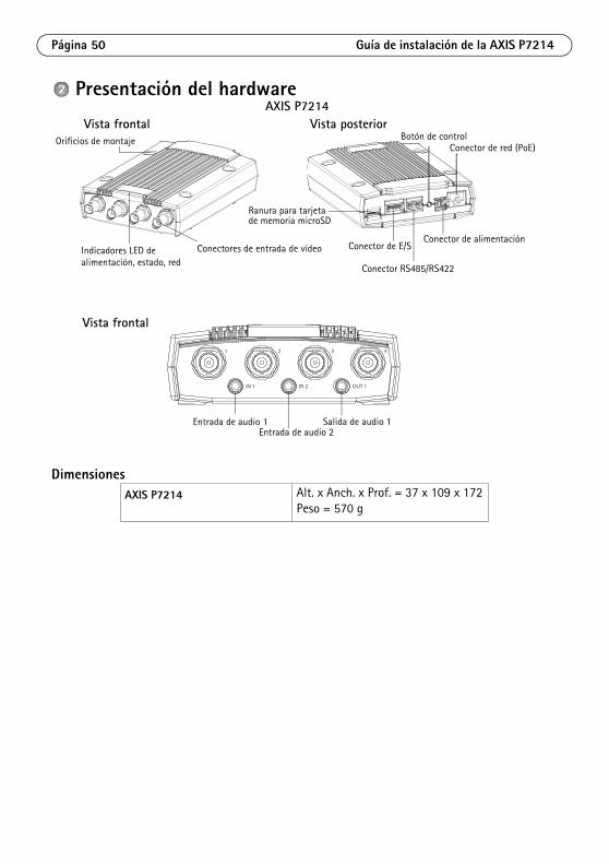
Presentación del hardware
DimensionesAXIS P7214 Alt. x Anch. x Prof. = 37 x 109 x 172
Peso = 570 g
Orificios de montaje
alimentación, estado, redIndicadores LED de
Conector de alimentación
Conector RS485/RS422
Conector de red (PoE)Botón de control
Conector de E/S
Ranura para tarjetade memoria microSD
Conectores de entrada de vídeo
Vista frontal Vista posterior
2 3 41
IN 1 IN 2 OUT 1
Entrada de audio 1 Salida de audio 1Entrada de audio 2
Vista frontal
AXIS P7214
Guía de instalación de la AXIS P7214 Página 51
ESPAÑO
L
Instale el hardware
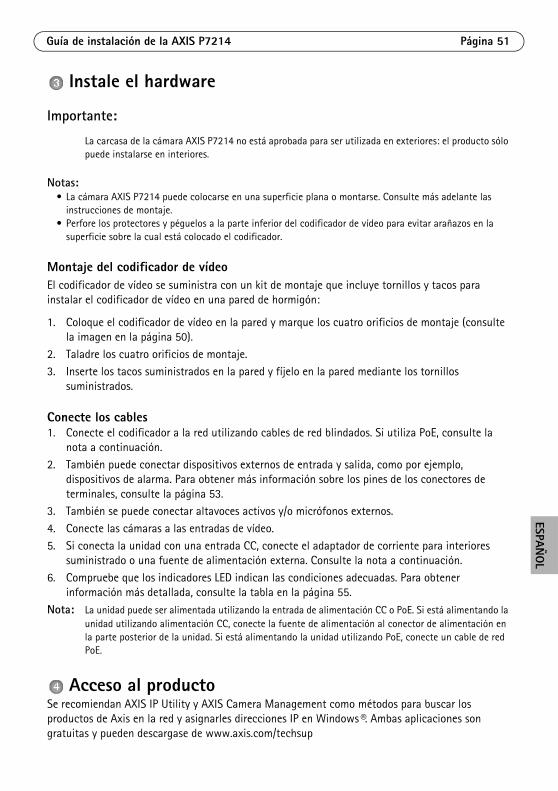
Importante:
La carcasa de la cámara AXIS P7214 no está aprobada para ser utilizada en exteriores: el producto sólo puede instalarse en interiores.
Notas:• La cámara AXIS P7214 puede colocarse en una superficie plana o montarse. Consulte más adelante las
instrucciones de montaje.• Perfore los protectores y péguelos a la parte inferior del codificador de vídeo para evitar arañazos en la
superficie sobre la cual está colocado el codificador.
Montaje del codificador de vídeoEl codificador de vídeo se suministra con un kit de montaje que incluye tornillos y tacos para instalar el codificador de vídeo en una pared de hormigón:
1. Coloque el codificador de vídeo en la pared y marque los cuatro orificios de montaje (consulte la imagen en la página 50).
2. Taladre los cuatro orificios de montaje.3. Inserte los tacos suministrados en la pared y fíjelo en la pared mediante los tornillos
suministrados.
Conecte los cables1. Conecte el codificador a la red utilizando cables de red blindados. Si utiliza PoE, consulte la
nota a continuación.
2. También puede conectar dispositivos externos de entrada y salida, como por ejemplo, dispositivos de alarma. Para obtener más información sobre los pines de los conectores de terminales, consulte la página 53.
3. También se puede conectar altavoces activos y/o micrófonos externos.
4. Conecte las cámaras a las entradas de vídeo.
5. Si conecta la unidad con una entrada CC, conecte el adaptador de corriente para interiores suministrado o una fuente de alimentación externa. Consulte la nota a continuación.
6. Compruebe que los indicadores LED indican las condiciones adecuadas. Para obtener información más detallada, consulte la tabla en la página 55.
Nota: La unidad puede ser alimentada utilizando la entrada de alimentación CC o PoE. Si está alimentando la unidad utilizando alimentación CC, conecte la fuente de alimentación al conector de alimentación en la parte posterior de la unidad. Si está alimentando la unidad utilizando PoE, conecte un cable de red PoE.
Acceso al productoSe recomiendan AXIS IP Utility y AXIS Camera Management como métodos para buscar los productos de Axis en la red y asignarles direcciones IP en Windows®. Ambas aplicaciones son gratuitas y pueden descargase de www.axis.com/techsup
Página 52 Guía de instalación de la AXIS P7214
El producto se puede utilizar con la mayoría de los sistemas operativos y navegadores. Los navegadores recomendados son
• Internet Explorer® con Windows®
• Safari® con OS X® y
• ChromeTM o Firefox® con otros sistemas operativos.Para obtener más información sobre el uso del producto, consulte el Manual del usuario, disponible en www.axis.com.
Guía de instalación de la AXIS P7214 Página 53
ESPAÑO
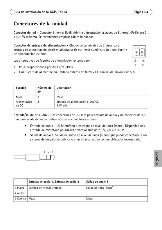
L
Conectores de la unidadConector de red - Conector Ethernet RJ45. Admite alimentación a través de Ethernet (PoE)clase 3: 12,95 W máximo. Se recomienda emplear cables blindados.
Conector de entrada de alimentación - Bloque de terminales de 2 pines para entrada de alimentación desde el adaptador de corriente suministrado o una fuente de alimentación externa.
Las alternativas de fuentes de alimentación externas son:
1. PS-K proporcionada por Axis P/N 349872. Una fuente de alimentación limitada externa de 8-20 V CC con salida máxima de 5 A.
Entrada/salida de audio - Dos conectores de 3,5 mm para entrada de audio y un conector de 3,5 mm para salida de audio. Deben utilizarse conectores estéreo.
• Entrada de audio 1, 2: Micrófono o entradas de nivel de línea (mono). Disponible una entrada de micrófono polarizada seleccionable de 2,0 V, 2,5 V o 3,0 V.
• Salida de audio 1: Salida de audio de nivel de línea (mono) que puede conectarse a un sistema de megafonía pública o a un altavoz activo con amplificador incorporado.
Función Número de pin
Descripción
Masa 1 Masa
Alimentación de CC
2 Entrada de alimentación 8-20V CC8 W máx
Entrada de audio 1, Entrada de audio 2 Salida de audio 1
1 Punta Entrada de línea/micrófono Salida de línea (mono)
2 Anillo
3 Camisa Masa Masa
1 2
123
Página 54 Guía de instalación de la AXIS P7214
Conector de terminales de E/S - Se utiliza en aplicaciones como detección de movimiento, activación por eventos, grabación a intervalos y notificaciones de alarma. Además de un pin de alimentación auxiliar y un pin de toma de tierra, la AXIS P7214 tiene 4 pines que pueden configurarse como entrada o salida. Estos pines proporcionan la interfaz para:
• Salida de transistor: para conectar dispositivos externos como relés y LED. Se pueden activar dispositivos conectados mediante AXIS VAPIX API, los botones de salida de la página Live View (En vivo) o mediante un Event Type (Tipo de evento). La salida se mostrará activa (Event Configuration [Configuración de eventos] > Port Status [Estado del puerto]) si el dispositivo de alarma está activado.
• Entrada digital: una entrada de alarma para conectar dispositivos que puedan alternar entre circuito cerrado y abierto, como por ejemplo: PIR, contactos de puertas y ventanas y detectores de rotura de cristales. Cuando se recibe una señal, el estado cambia y la entrada se vuelve activa [indicado en Event Configuration (Configuración de eventos) > Port Status (Estado del puerto)].
Función Pin Notas Especificaciones
Masa 1 Masa
Salida de alimentación de 3,3 V CC
2 Se puede utilizar para alimentar equipos auxiliares.
Carga máx. = 250 mA
Configurable (entrada o salida)
3 - 6 Entrada digital: conecte a GND (masa) para activarla o déjela suelta (o desconectada) para desactivarla.
0 a + 40 V CC
Salida digital: conexión interna a masa cuando esté activada, suelta (desconectada) cuando esté desactivada. Si se utiliza con un relé externo, debe conectarse un diodo en paralelo a la carga como protección ante oscilaciones de tensión.
Carga máx. = 100 mAVoltaje máx. = + 40 V CC
Guía de instalación de la AXIS P7214 Página 55
ESPAÑO
L
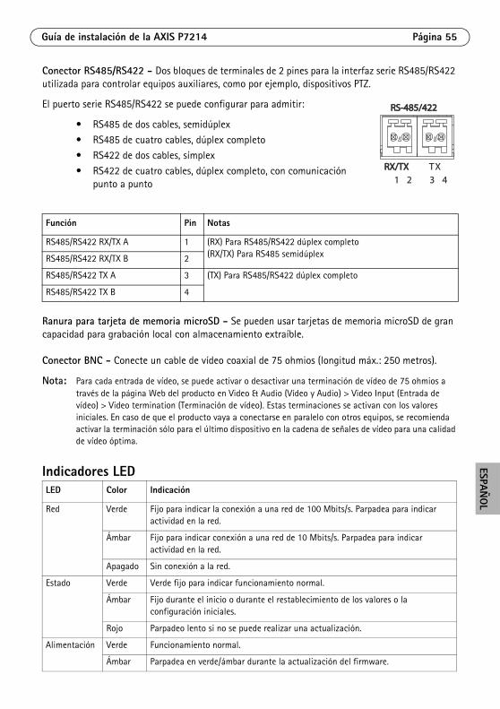
Conector RS485/RS422 - Dos bloques de terminales de 2 pines para la interfaz serie RS485/RS422 utilizada para controlar equipos auxiliares, como por ejemplo, dispositivos PTZ.
El puerto serie RS485/RS422 se puede configurar para admitir:
• RS485 de dos cables, semidúplex• RS485 de cuatro cables, dúplex completo
• RS422 de dos cables, símplex
• RS422 de cuatro cables, dúplex completo, con comunicación punto a punto
Ranura para tarjeta de memoria microSD - Se pueden usar tarjetas de memoria microSD de gran capacidad para grabación local con almacenamiento extraíble.
Conector BNC - Conecte un cable de vídeo coaxial de 75 ohmios (longitud máx.: 250 metros).
Nota: Para cada entrada de vídeo, se puede activar o desactivar una terminación de vídeo de 75 ohmios a través de la página Web del producto en Video & Audio (Vídeo y Audio) > Video Input (Entrada de vídeo) > Video termination (Terminación de vídeo). Estas terminaciones se activan con los valores iniciales. En caso de que el producto vaya a conectarse en paralelo con otros equipos, se recomienda activar la terminación sólo para el último dispositivo en la cadena de señales de vídeo para una calidad de vídeo óptima.
Indicadores LED
Función Pin Notas
RS485/RS422 RX/TX A 1 (RX) Para RS485/RS422 dúplex completo(RX/TX) Para RS485 semidúplexRS485/RS422 RX/TX B 2
RS485/RS422 TX A 3 (TX) Para RS485/RS422 dúplex completo
RS485/RS422 TX B 4
LED Color Indicación
Red Verde Fijo para indicar la conexión a una red de 100 Mbits/s. Parpadea para indicar actividad en la red.
Ámbar Fijo para indicar conexión a una red de 10 Mbits/s. Parpadea para indicar actividad en la red.
Apagado Sin conexión a la red.
Estado Verde Verde fijo para indicar funcionamiento normal.
Ámbar Fijo durante el inicio o durante el restablecimiento de los valores o la configuración iniciales.
Rojo Parpadeo lento si no se puede realizar una actualización.
Alimentación Verde Funcionamiento normal.
Ámbar Parpadea en verde/ámbar durante la actualización del firmware.
RS-485/422RS-485/422
RX/TXRX/TX1 2 3 4
TX
Página 56 Guía de instalación de la AXIS P7214
Restablecimiento de los valores inicialesEsta operación restaurará todos los parámetros, incluida la dirección IP, a los valores iniciales:
1. Desconecte la alimentación del AXIS P7214 o, si se utiliza PoE, desconecte el cable de red.2. Mantenga pulsado el botón de control y vuelva a conectar la alimentación o el cable de red si
se utiliza PoE.3. Mantenga pulsado el botón de Control hasta que el indicador de estado emita una luz ámbar
(puede tardar hasta 15 segundos en encenderse).4. Suelte el botón de control. Cuando el indicador de estado emita una luz verde (lo que puede
tardar hasta 1 minuto), ha finalizado el proceso y se han restablecido los valores iniciales del codificador de vídeo.
5. Vuelva a asignar la dirección IP utilizando uno de los métodos descritos en este documento.También es posible restablecer los parámetros a la configuración predeterminada original mediante la interfaz Web. Para obtener más información, consulte la ayuda en línea o el manual del usuario.
Más informaciónEl manual del usuario está disponible en el sitio Web de Axis, www.axis.com
GarantíaPara información sobre la garantía de productos Axis e información relacionada, por favor consulte www.axis.com/warranty
Un consejo: Visite www.axis.com/techsup para comprobar si existe algún firmware actualizado disponible para su AXIS P7214. Para ver la versión de firmware que tiene instalada actualmente, consulte la página Web About (Acerca de).


Installation Guide Ver. 3.0
AXIS P7214 Video Encoder Printed: August 2015
©xis Communications AB 2011-2012 Part No. 48564