axial turbine flow meters - test & measurement instruments with
TRANSCRIPT

COMPANY
Installation, Operating & Maintenance Manual
Sanitary Turbine Flow Meter - TA3
©2016 AW-Lake Company. All rights reserved. Doc ID:SANITARYMAN16

2
Mechanical Specifications
Materials of Construction
Body & Rotor Support 316L Stainless Steel
Rotor Nickel Plated Stainless Steel
Bearings Nickel Bindery Tungsten Carbide
Maximum Operating Pressure**
Working pressure up to 1,000 psi
Temperature Range*
Fluid temperature up to 300°F
Electrical ConnectionNEMA 6 Connector
Port Connection Tri-clamp
Measuring Accuracy± 1.0% of reading or better
Repeatability± 0.1%
Flow Measuring Range0.6 to 400 GPM (gal/min)
Turn Down Ratio10:1
Electronics
*Sensor & seal dependent. ** Depends on connection size & clamp. Note: .COP (Clean-Out-of-Place)
*Contact factory for additional sensor options.
Model Sensor Type Temp (°F)
RT-10R Battery-Powered Monitor 0 to 140
RT-30SD 15-24 VDC Powered Monitor 0 to 140
MAG-INVA Amplified Pulse Output 0 to 140
MG-300 Non-Amplified (external amplifer needed) 0 to 300
MG-450 Non-Amplified (external amplifer needed) 0 to 450
3
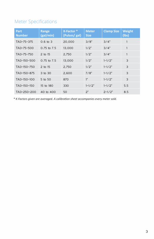
Meter Specifications
Part Number
Range (gal/min)
K-Factor * (Pulses/ gal)
Meter Size
Clamp Size Weight (lbs)
TA3-75-375 0.6 to 3 20,000 3/8” 3/4” 1
TA3-75-500 0.75 to 7.5 13,000 1/2” 3/4” 1
TA3-75-750 2 to 15 2,750 1/2” 3/4” 1
TA3-150-500 0.75 to 7.5 13,000 1/2” 1-1/2” 3
TA3-150-750 2 to 15 2,750 1/2” 1-1/2” 3
TA3-150-875 3 to 30 2,600 7/8” 1-1/2” 3
TA3-150-100 5 to 50 870 1” 1-1/2” 3
TA3-150-150 15 to 180 330 1-1/2” 1-1/2” 5.5
TA3-250-200 40 to 400 50 2” 2-1/2” 8.5
* K-Factors given are averaged. A calibration sheet accompanies every meter sold.

4
IntroductionThe TA-3 Sanitary turbine flow meter is designed with wear resistant moving parts to provide trouble-free operation and long service life. The durable 316L stainless steel construction provides a cost efficient flow measurement system that offers excellent accuracy and repeatability. The TA-3 Sanitary turbine meter repair kit is designed for easy field service of a damaged flow meter, rather than replacing the entire flow meter. See Repair Kits on page 8 for information.
Theory of Operation
Fluid entering the meter passes through the inlet flow straightener which reduces its turbulent flow pattern and improves the fluid’s velocity profile. Fluid then passes through the turbine, causing the rotor to rotate at a speed proportional to the fluid velocity. As each turbine blade passes through the magnetic field, the blade generates an AC voltage pulse in the pickup coil at the base of the magnetic pickup (see Figure 1). These pulses produce an output frequency proportional to the volumetric flow through the meter. The output frequency represents flow rate and/or totalization of fluid passing through the turbine flow meter.
Rotor
MagneticPickup
Output Signal
Figure 1. Theory of Operation

5
InstallationWARNING: The meter should not be subjected to temperatures above 300° F (149° C), below -150° F (-101°C) or the freezing point of the metered liquid. High temperatures will damage the magnetic pickup, while lower temperatures will limit the rotation of the rotor.
WARNING: Incompatible fluids could deteriorte internal parts and cause the meter to read inaccurately.
Plumbing
Install the flow meter with the flow arrow, which is etched on the exterior of the meter body, pointing in the direction of fluid flow. Install the meter horizontally with the magnetic pickup facing upward.
The liquid being measured must be free of any large particles that may obstruct spinning of the rotor. If particles are present, install a mesh strainer.
If small particles are present in the fluid, install a strainer upstream of the meter. See Table 1 for filtration recommendations.
Bore Size Ferrule Size Strainer Size Clearance
3/8 in. (9.53 mm) 0.984 in. (24.99 mm) 60 × 60 0.0092 in. (0.23 mm)
1/2 in. (12.7 mm) 0.984 in. (24.99 mm) 60 × 60 0.0092 in. (0.23 mm)
3/4 in. (19.05 mm) 0.984 in. (24.99 mm) 60 × 60 0.0092 in. (0.23 mm)
1/2 in. (12.7 mm) 1.984 in. (50.39 mm) 60 × 60 0.0092 in. (0.23 mm)
3/4 in. (19.05 mm) 1.984 in. (50.39 mm) 60 × 60 0.0092 in. (0.23 mm)
7⁄8 in. (22.23 mm) 1.984 in. (50.39 mm) 60 × 60 0.0092 in. (0.23 mm)
1 in. (25.4 mm) 1.984 in. (50.39 mm) 60 × 60 0.0092 in. (0.23 mm)
1-1/2 in. (38.1 mm) 1.984 in. (50.39 mm) 20 × 20 0.034 in. (0.86 mm)
2 in. (50.8 mm) 3.047 in. (77.39 mm) 10 × 10 0.065 in. (16.51 mm)
Table 1

6
Severe pulsation and mechanical vibration affects accuracy and shortens the life of the meter.
The preferred plumbing setup is one containing a bypass line that allows meter inspection and repair without interrupting flow. See Figure 2. If a bypass line is not utilized, it is important that all control valves be located downstream of the flow meter. See Figure 3.
This is true with any restriction in the flow line that may cause the liquid to flash. If necessary, air eliminators should be installed to ensure that the meter is not incorrectly measuring entrained air or gas.
Bypass Line
4 1647
5 Pipe DiametersMinimum
10 Pipe DiametersMinimum
IsolationValve
TA-3 Sanitary TurbineFlow Meter
IsolationValve
Figure 2: Installation with bypass line
Figure 3: Installation without a bypass line
4 1647
5 Pipe DiametersMinimum
10 Pipe DiametersMinimum
TA-3 Sanitary TurbineFlow Meter Isolation
Valve
It is recommended that a minimum length, equal to ten (10) pipe diameters of straight pipe, be installed on the upstream side and five (5) diameters on the downstream side of the flow meter. Otherwise, meter accuracy may be affected. Piping should be the same size as the meter bore or threaded port size.

7
Do not locate the flow meter or connection cable close to electric motors, transformers, sparking devices, high voltage lines, or place connecting cable in conduit with wires furnishing power for such devices. These devices can induce false signals in the flow meter coil or cable causing the meter to read inaccurately.
WARNING: Damage can be caused by striking an emply meter with a high velocity flow stream.
If problems arise with the flow meter and monitor, consult the “Troubleshooting Guide” on page 13. If further problems arise, consult the factory. If the internal components of the turbine flow meter are damaged, order a turbine meter repair kit. See “Repair Kits” on page 10.
Operational Startup
The following steps should be followed when installing and starting the meter.
WARNING: Make sure that fluid flow has been shut off and pressure in the line released before attempting to install the meter in an existing system.
1. After meter installation, keep the isolation valves closed and the bypass valve open. Flow liquid through the bypass valve for sufficient time to eliminate any air or gas in the flow line.
2. Open upstream isolating valve slowly to eliminate hydraulic shock while charging the meter with the liquid. Open the valve to full open.
CAUTION: High velocity air or gas may damage the internal components of the meter.
3. Open downstream isolating valve to permit meter to operate.4. Close the bypass valve to a full closed position.5. Adjust the downstream valve to provide the required flow rate through the
meter.
NOTE: The downstream valve may be used as a control valve.

8
Dimensions and Drawings
A B
C
Figure 5: Dimensions
Part Number A B C
TA3-75-375 3.00 in. (76 mm) 1.5 in. (38 mm) 1 in. (25 mm)
TA3-75-500 3.00 in. (76 mm) 1.5 in. (38 mm) 1 in. (25 mm)
TA3-75-750 3.00 in. (76 mm) 1.5 in. (38 mm) 1 in. (25 mm)
TA3-150-500 4 in. (101 mm) 2.0 in. (50 mm) 2.0 in. (50 mm)
TA3-150-750 4 in. (101 mm) 2.0 in. (50 mm) 2.0 in. (50 mm)
TA3-150-875 4 in. (101 mm) 2.0 in. (50 mm) 2.0 in. (50 mm)
TA3-150-100 4 in. (101 mm) 2.0 in. (50 mm) 2.0 in. (50 mm)
TA3-150-150 6.25 in. (158 mm) 2.3 in. (59 mm) 2.0 in. (50 mm)
TA3-250-200 6.5 in. (161 mm) 2.3 in. (59 mm) 3 in. (76 mm)
Table 4: Dimensions
9
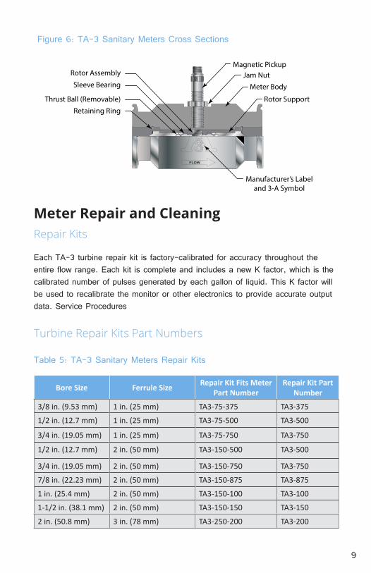
Retaining Ring
Thrust Ball (Removable)
Sleeve Bearing
Rotor Assembly
Meter Body
Jam NutMagnetic Pickup
Rotor Support
Manufacturer’s Labeland 3-A Symbol
Figure 6: TA-3 Sanitary Meters Cross Sections
Meter Repair and CleaningRepair Kits
Each TA-3 turbine repair kit is factory-calibrated for accuracy throughout the entire flow range. Each kit is complete and includes a new K factor, which is the calibrated number of pulses generated by each gallon of liquid. This K factor will be used to recalibrate the monitor or other electronics to provide accurate output data. Service Procedures
Bore Size Ferrule Size Repair Kit Fits Meter Part Number
Repair Kit Part Number
3/8 in. (9.53 mm) 1 in. (25 mm) TA3-75-375 TA3-375
1/2 in. (12.7 mm) 1 in. (25 mm) TA3-75-500 TA3-500
3/4 in. (19.05 mm) 1 in. (25 mm) TA3-75-750 TA3-750
1/2 in. (12.7 mm) 2 in. (50 mm) TA3-150-500 TA3-500
3/4 in. (19.05 mm) 2 in. (50 mm) TA3-150-750 TA3-750
7/8 in. (22.23 mm) 2 in. (50 mm) TA3-150-875 TA3-875
1 in. (25.4 mm) 2 in. (50 mm) TA3-150-100 TA3-100
1-1/2 in. (38.1 mm) 2 in. (50 mm) TA3-150-150 TA3-150
2 in. (50.8 mm) 3 in. (78 mm) TA3-250-200 TA3-200
Turbine Repair Kits Part Numbers
Table 5: TA-3 Sanitary Meters Repair Kits
10
3-A Turbine Disassembly and Cleaning Procedure
WARNING: High-pressure leaks are dangerous and cause personal injury. Make sure that fluid flow had been shut off and pressure in the line released before attempting to remove the meter.
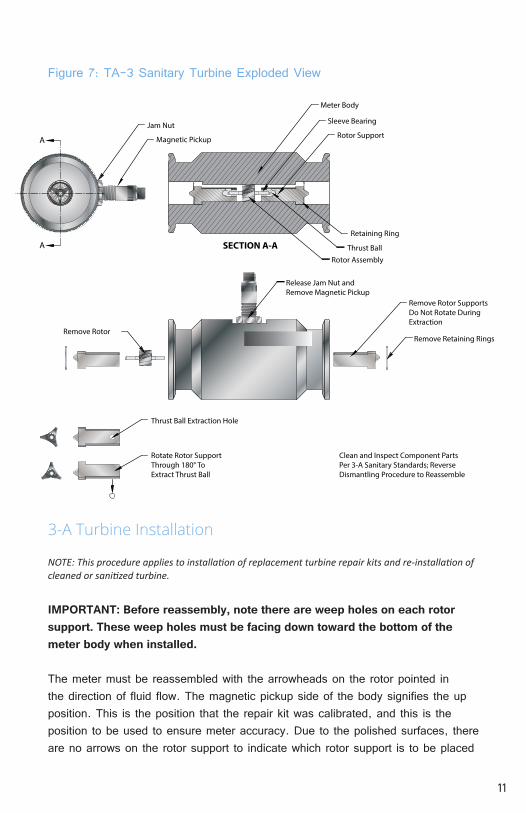
NOTE: Refer to Figure 7 for relative positions of repair kit components.
1. Remove the magnetic pickup from the meter body to avoid damage during procedure.
2. Remove the retaining ring from one end of the meter.3. Keeping the meter upright (pickup port at the top), remove the rotor support
from the body, taking care not to rotate it in the process. If the rotor support is jammed in the body, use a pair of pliers or vice grips to break it free.
4. Hold the rotor support over a suitable container and rotate it through 180°. The thrust ball will drop out. Take care not to lose the ball.
5. Remove the rotor assembly.6. Remove the second retaining ring from the opposite side of the meter.7. Repeat steps 3 and 4 for the remaining rotor support.8. Identify parts and flow direction to match with original meter body.9. Clean and/or sanitize parts to meet appropriate sanitary standards.
11
Remove Rotor
Thrust Ball Extraction Hole
Rotate Rotor SupportThrough 180° ToExtract Thrust Ball
Retaining Ring
Thrust BallRotor Assembly
Release Jam Nut andRemove Magnetic Pickup
SECTION A-AA
Clean and Inspect Component PartsPer 3-A Sanitary Standards; ReverseDismantling Procedure to Reassemble
Remove Retaining Rings
Remove Rotor SupportsDo Not Rotate DuringExtraction
Jam Nut
Magnetic PickupA Rotor Support
Sleeve Bearing
Meter Body
Figure 7: TA-3 Sanitary Turbine Exploded View
3-A Turbine Installation
NOTE: This procedure applies to installation of replacement turbine repair kits and re-installation of cleaned or sanitized turbine.
IMPORTANT: Before reassembly, note there are weep holes on each rotor support. These weep holes must be facing down toward the bottom of the meter body when installed.
The meter must be reassembled with the arrowheads on the rotor pointed in the direction of fluid flow. The magnetic pickup side of the body signifies the up position. This is the position that the repair kit was calibrated, and this is the position to be used to ensure meter accuracy. Due to the polished surfaces, there are no arrows on the rotor support to indicate which rotor support is to be placed

12
upstream or downstream. Please install the repair kit as it was received in the box, using the arrow on the rotor to determine the placement of the rotor support.
1. If required by process procedures, the meter should be cleaned prior to installation into the piping system.
2. Drop a thrust ball into a rotor support through the hole provided in the side. Insert rotor support into the meter body. Keep the thrust bearing hole pointed upwards to keep the ball in place.
3. Secure a retaining ring in the groove provided. Be sure that the retaining ring is completely installed in the groove.
4. Drop a thrust ball into second rotor support through the hole provided in the side. Locate the rotor in the support sleeve bearing. Insert rotor support and rotor into the meter body and the first support sleeve bearing. Keep the thrust bearing hole pointed upwards to keep the ball in place.
5. Secure the second retaining ring in the groove provided. Be sure that the retaining ring is completely installed in the groove.
WARNING: Excess air pressure may damage the rotor and bearings by over-spin.
6. Check the meter by blowing air through the assembly. If the rotor does not turn freely, the meter should be disassembled and checked for anything that would obstruct movement of the rotor.
7. Install the magnetic pickup.
NOTE: After installing the new repair kit, the electronics will need re-calibration. Refer to the electronics’ installation and operation manual. If there are any questions on re-calibration, contact AW-Lake Company at 1.800.850.6110 or contact the manufacturer of the associated electronics.

13
Troubleshooting Guide

14

15

262.884.9800 | www.aw-lake.com2440 W. Corporate Preserve Dr. #600 Oak Creek, WI 53154
COMPANY
©2016 AW-Lake Company. All rights reserved. Doc ID:SANITARYMAN16