axial piston variable pump (a)a10vso (us-version) · data sheet axial piston variable pump...
TRANSCRIPT
Linear Motion andAssembly Technologies ServicePneumaticsHydraulics
Electric Drives and Controls
Data Sheet
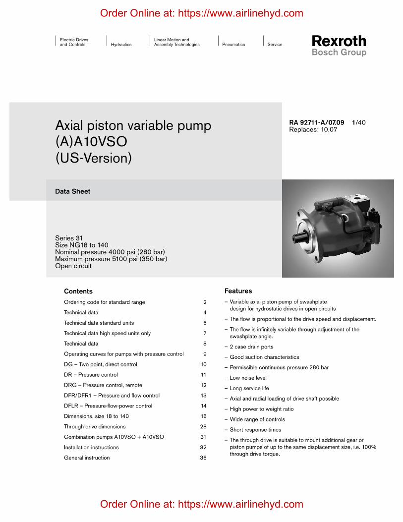
Axial piston variable pump(A)A10VSO(US-Version)
RA 92711-A/07.09 1/40Replaces: 10.07
Series 31Size NG18 to 140Nominal pressure 4000 psi (280 bar)Maximum pressure 5100 psi (350 bar)Open circuit
FeaturesVariable axial piston pump of swashplate –design for hydrostatic drives in open circuits
The flow is proportional to the drive speed and displacement. –
The flow is infinitely variable through adjustment of the –swashplate angle.
2 case drain ports –
Good suction characteristics –
Permissible continuous pressure 280 bar –
Low noise level –
Long service life –
Axial and radial loading of drive shaft possible –
High power to weight ratio –
Wide range of controls –
Short response times –
The through drive is suitable to mount additional gear or –piston pumps of up to the same displacement size, i.e. 100%through drive torque.
ContentsOrdering code for standard range 2
Technical data 4
Technical data standard units 6
Technical data high speed units only 7
Technical data 8
Operating curves for pumps with pressure control 9
DG – Two point, direct control 10
DR – Pressure control 11
DRG – Pressure control, remote 12
DFR/DFR1 – Pressure and flow control 13
DFLR – Pressure-flow-power control 14
Dimensions, size 18 to 140 16
Through drive dimensions 28
Combination pumps A10VSO + A10VSO 31
Installation instructions 32
General instruction 36
Order Online at: https://www.airlinehyd.com
Order Online at: https://www.airlinehyd.com

2/36 Bosch Rexroth Corporation (A)A10VSO | RA 92711-A/07.09
Type of rotary group 18 28 45 71 100 140
01HFA, HFB, HFC -Fluids – E
High-Speed-Version – – H
Axial Piston Unit 18 28 45 71 100 14002 Swashplate design, variable (A)A10VS
Operating mode03 Pump, open circuit O
Size
04 Displacement Vg max inin 1.10 1.71 2.75 4.33 6.10 8.54
(cm3) (18) (28) (45) (71) (100) (140)
Control devices 18 28 45 71 100 140
05
Two-point control, directly operated DG
Pressure control DR
hydraulic, remotely controled DRG
with hydraulic flow control,X - T open DFRX - T closed with flushing function DFR1
electric displacement control with press. control DFE11)
electric pressure control, inverse proportional curve ED2)
Pressure, flow and power control – DFLR
Series06 Series 3, Index 1 31
Direction of rotation
07Viewed from drive shaft clockwise R
counter-clockwise L
Seals08 FKM (Fluor-caoutchouc) V
Drive shaft 18 28 45 71 100 140
09
Splined shaft, ANSI B92.1a, standard shaft S
Similar to shaft „S“ however for higher input torque – – R
Splined shaft to SAE J744, reduced diameter, not for through drive – – – – U
Parallel shaft SAE with key J744 (ISO 3019-1) K
Mounting flange 18 28 45 71 100 140
10SAE J744 – 2-bolt – C
SAE J744 – 4-bolt – – – – – D
(A)A10VS O / 31 – V01 02 03 04 05 06 07 08 09 10 11 12
Ordering code for standard range
1) see RE 30030 2) see RE 92707
= Available m = In preperation – Not available ▲ = Not for new projects = Preferred program
Order Online at: https://www.airlinehyd.com
Order Online at: https://www.airlinehyd.com

RA 92711-A/07.09 | (A)A10VSO Bosch Rexroth Corporation 3/36
(A)A10VS O / 31 – V01 02 03 04 05 06 07 08 09 10 11 12
Ordering code for standard range
Service line ports 18 28 45 71 100 140
11
SAE flanged ports at opposite side, UNC mounting bolts – 62
SAE flanged ports at opposite side, UNC mounting bolts
– – – – – 92
Through drive 18 28 45 71 100 140
12
Without through drive N00
Flange SAE J744
Coupling for splined shaft1)
82-2 (A) 5/8 in 9T 16/32DP 16-4 (A) K01
82-2 (A) 3/4 in 11T 16/32DP 19-4 (A-B) K52
101-2 (B) 7/8 in 13T 16/32DP 22-4 (B) – K68
101-2 (B) 1 in 15T 16/32DP 25-4 (B-B) – K04
127-2 (C) 1 1/4 in 14T 12/24DP 32-4 (C) – – – K07
127-2 (C) 1 1/2 in 17T 12/24DP 38-4 (C-C) – – – – K24
152-4 (D) 1 3/4 in 13T 8/16DP 44-4 (D) – – – – – K171) Coupler for splined shaft to ANSI B92.1a-1976 (spline execution to SAE J744)
= Available m = In preperation – Not available ▲ = Not for new projects = Preferred program
Order Online at: https://www.airlinehyd.com
Order Online at: https://www.airlinehyd.com
4/36 Bosch Rexroth Corporation (A)A10VSO | RA 92711-A/07.09
-40° -4° 32° 68° 104° 140° 176° 212° °F
-40° -20° 0° 20° 40° 60° 80° 100° °C
-40° -25° 10° 0° 10° 30° °C50° 70° 90° 115°
-40° -13° 14° 32° 50° 86° °F122° 158° 194° 240°
160074001000460060030004002000
2001000
100500
60300
40200
20100
1060
mm2/sSUS542
80
74001600
17036
8016
425SUSmm2/s
t max = 240°F (115°C)t min = -40°F (-40°C)
VG 22VG 32VG 46VG 68VG 100
Technical DataHydraulic fluidsPrior to project design, please see our technical data sheets RE 90220 (mineral oil), RE 90221 (environmentally acceptable fluids) and RE 90223 (HF-fluids) for detailed information on fluids and operating conditions.
When using HF- or environmentally acceptable fluids attenti-on must be paid to possible limitations of the technical data, if necessary contact us. (when ordering please state in clear text the fluid to be used). For operation on Skydrol fluid please consult us.
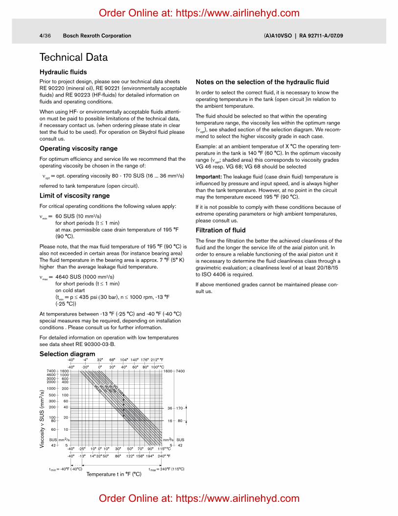
Operating viscosity rangeFor optimum efficiency and service life we recommend that the operating viscosity be chosen in the range of:
nopt = opt. operating viscosity 80 - 170 SUS (16 ... 36 mm2/s)
referred to tank temperature (open circuit).
Limit of viscosity rangeFor critical operating conditions the following values apply:
nmin = 60 SUS (10 mm2/s) for short periods (t ≤ 1 min) at max. permissible case drain temperature of 195 °F (90 °C).
Please note, that the max fluid temperature of 195 °F (90 °C) is also not exceeded in certain areas (for instance bearing area) The fluid temperature in the bearing area is approx. 7 °F (5° K) higher than the average leakage fluid temperature.
nmax = 4640 SUS (1000 mm2/s) for short periods (t ≤ 1 min) on cold start (tmin = p ≤ 435 psi (30 bar), n ≤ 1000 rpm, -13 °F (-25 °C))
At temperatures between -13 °F (-25 °C) and -40 °F (-40 °C) special measures may be required, depending on installation conditions . Please consult us for further information.
For detailed information on operation with low temperatures see data sheet RE 90300-03-B.
Selection diagram
Notes on the selection of the hydraulic fluidIn order to select the correct fluid, it is necessary to know the operating temperature in the tank (open circuit )in relation to the ambient temperature.
The fluid should be selected so that within the operating temperature range, the viscosity lies within the optimum range (nopt), see shaded section of the selection diagram. We recom-mend to select the higher viscosity grade in each case.
Example: at an ambient temperatue of X °C the operating tem-perature in the tank is 140 °F (60 °C). In the optimum viscosity range (nopt; shaded area) this corresponds to viscosity grades VG 46 resp. VG 68; VG 68 should be selected
Important: The leakage fluid (case drain fluid) temperature is influenced by pressure and input speed, and is always higher than the tank temperature. However, at no point in the circuit may the temperature exceed 195 °F (90 °C).
If it is not possible to comply with these conditions because of extreme operating parameters or high ambient temperatures, please consult us.
Filtration of fluidThe finer the filtration the better the achieved cleanliness of the fluid and the longer the service life of the axial piston unit. In order to ensure a reliable functioning of the axial piston unit it is necessary to determine the fluid cleanliness class through a gravimetric evaluation; a cleanliness level of at least 20/18/15 to ISO 4406 is required.
If above mentioned grades cannot be maintained please con-sult us.
Visc
osity
n S
US
(m
m2 /
s)
Temperature t in °F (°C)
Order Online at: https://www.airlinehyd.com
Order Online at: https://www.airlinehyd.com

RA 92711-A/07.09 | (A)A10VSO Bosch Rexroth Corporation 5/36
Technical DataOperating pressure rangeDirection of flow
S to B
Pressure at suction port S (inlet)
Inlet pressure
pabs min _________________________ 12 psi (0,8 bar) absolute
pabs max ________________________145 psi (10 bar)1) absolute
Minimum permissible inlet pressure at port S at increased drive speed
In order to prevent damage to the pump (through cavitation) it is necesssary to maintain a minimum inlet pressure. This minimum required inlet pressure level depends on the drive speed and the pump displacement. These values do not apply however to the High-Speed version (see table of values on page 7).
Spe
ed n
/n m
ax
Displacement Vg/Vg max
(1,4)
(1,6)
(1,2)
(1,0)
(0,9)
(0,8)
20
23
(bar) psi
17,5
14,5
13
11,51,00,90,80,7
1,2
1,1
1,0
0,9
Case drain pressure
Maximum case drain pressure (at ports L, L1): Maximum 7 psi (0,5 bar) higher than the inlet pressure at port S, but not higher than 29 psi (2 bar) absolut.
pL max abs ________________________________29 psi (2 bar) 1)
Pressure at service line port (pressure port) B
Nominal pressure pnom ________ 4000 psi (280 bar) absolute
Maximum pressure pmax ______ 5100 psi (350 bar) absolute Total duration of exertion __________________________ 300 h Single duration of exertion ________________________ 2,5 ms
Minimum outlet pressure _______________145 psi (10 bar)1)
Rate of pressure change RA ___ 232060 psi/s (16000 bar/s)
pnom
Dt
Dp
time tP
ress
ure
pTo safeguard against over pressure pump safety blocks to RE 25880 and RE 25890 for direct mounting onto the SAE flange ports can be ordered separately.
Definition
Nominal pressure pnomThe nominal pressure corresponds to the maximum design pressure.
Maximum pressure pmaxThe maximum pressure corresponds to the maximum operating pressure within the single operating period. The sum of the single operating periods must not exceed the total operating period.
Minimum pressure (high-pressure side)Minimum pressure in the pump outlet side (port B) that is required in order to prevent damage to the axial piston unit.
Rate of pressure change RAMaximum permissible pressure build-up and pressure reduc-tion speed with a pressure change over the entire pressure range.
Pre
ssur
e p t1
t2 tnIndividual operating period
Minimum pressure (in pump outlet)
Peak pressure pmaxNominal pressure pnom
Time t
Total operating period = t1 + t2 + ... + tn1) Other datas on request
Inle
t pre
ssur
e p a
bs
Order Online at: https://www.airlinehyd.com
Order Online at: https://www.airlinehyd.com

6/36 Bosch Rexroth Corporation (A)A10VSO | RA 92711-A/07.09
Table of values (theoretical values, without efficiencies and tolerances; values rounded )
Size NG 18 28 45 71 100 140
Displacement
variable pump Vg max in3 (cm3) 1.10 (18) 1.71 (28) 2.75 (45) 4.33 (71) 6.1 (100) 8.54 (140)
Speed1)
maximum at Vg max nmax rpm 3300 3000 2600 2200 2000 1800
maximum at Vg < Vg max2) nmax perm. rpm 3900 3600 3100 2600 2400 2100
Flow
at nmax und Vg max qv max gpm 15.7 22 31 41 53 67
(L/min) (59) (84) (117) (156) (200) (252)
at n = 1800 rpm qv gpm 7.2 13.3 21.4 33.8 47.6 67
(L/min) (32) (59) (81) (128) (180) (252)
Power
at nmax Dp = 4000 psi Pmax HP 36.6 51 72 96 124 156
Dp = 280 bar (kW) (30) (39) (55) (73) (93) (118)
at n = 1800 rpm P HP( kW) 19 (15) 31 (24) 50 (38) 79 (69) 111 (84) 156 (118)
Torque
Dp = 4000 psi Tmax lb-ft 58 91 146 230 324 453
at Vg max and Dp = 280 bar (Nm) (80) (125) (200) (316) (445) (623)
Dp = 1450 psi T lb-ft 14.6 33 53 83 117 164
Dp = 100 bar (Nm) (30) (45) (72) (113) (159) (223)Torsional stiffness Drive shaft S c lb-ft/rad 8082 16400 27560 53018 89348 125042
(Nm/rad) (11000) (22300) (37500) (71884) (121142) (169537)
Drive shaft R c lb-ft/rad 10870 19400 30240 56456 – –
(Nm/rad) (14800) (26300) (41000) (76545) (–) (–)
Drive shaft U lb-ft/rad 5946 12310 22107 38920 67180 –
(Nm/rad) (8090) (16695) (30077) (52779) (91093) (–)
Drive shaft K c lb-ft/rad 9805 19712 32270 60352 99448 144680
(Nm/rad) (13340) (26189) (43905) (82112) (135303) (196844)
Moment of inertia rotary unit
JTWlbs-ft2 (kgm2)
0.022 (0.00093)
0.0403 (0.0017)
0.0783 (0.0033)
0.1970 (0.0083)
0.3963 (0.0167)
0.5743 (0.0242)
Case volume V gal (L) 0.1 (0.4) 0.2 (0.7) 0.26 (1.0) 0.4 (1.6) 0.6 (2.2) 0.8 (3.0)
Weight (without through drive) approx.
m lbs (kg) 26.5 (12) 33 (15) 46 (21) 73 (33) 99 (45) 132 (60)
1) Values shown are valid for an absolute pressure (pabs) of 15 psi (1 bar) at inlet port S and use with mineral oil(with a specific weight of 0,0073 lb/gal (0,88kg/L)).
2) Values are valid for Vg ≤ Vg max or increase of inlet pressure pabs at inlet port S (see diagram page 5)
Note Exceeding the maximum or falling below the minimum permissible values can lead to a loss of function, a reduction in operational service life or total destruction of the axial piston unit. The permissible values can be determined through calculation.
Determination of size
Flow qV =Vg • n • hV [gpm
(L/min)]Vg = Displacement per revolution in in3 (cm3)
231 (1000) Dp = Differential pressure in psi (bar)
Torque T =Vg • Dp [lb-ft
(Nm)]n = Speed in rpm (min-1)
24 (20) • p • hmh hV = Volumetric efficiency
Power P =2p • T • n
=qV • Dp [HP
(kW)]hmh = Mechanical-hydraulic efficiency
33000 (60000) 1714 (600) • ht ht = Total efficiency (ht = hV • hmh)
Technical data standard units
Order Online at: https://www.airlinehyd.com
Order Online at: https://www.airlinehyd.com
RA 92711-A/07.09 | (A)A10VSO Bosch Rexroth Corporation 7/36
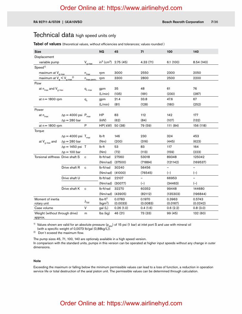
Tabel of values (theoretical values, without efficiencies and tolerances; values rounded )
Size NG 45 71 100 140
Displacement
variable pump Vg max in3 (cm3) 2.75 (45) 4.33 (71) 6.1 (100) 8.54 (140)
Speed1)
maximum at Vg max nmax rpm 3000 2550 2300 2050
maximum at Vg < Vg max2) nmax perm. rpm 3300 2800 2500 2200
Flow
at nmax and Vg max qv max gpm 35 48 61 76
(L/min) (135) (181) (230) (287)
at n = 1800 rpm qv gpm 21.4 33.8 47.6 67
(L/min) (81) (128) (180) (252)
Power
at nmax Dp = 4000 psi Pmax HP 83 112 142 177
Dp = 280 bar (kW) (62) (84) (107) (132)
at n = 1800 rpm P HP( kW) 50 (38) 79 (59) 111 (84) 156 (118)
Torque
Dp = 4000 psi Tmax lb-ft 146 230 324 453
at Vg max and Dp = 280 bar (Nm) (200) (316) (445) (623)
Dp = 1450 psi T lb-ft 53 83 117 164
Dp = 100 bar (Nm) (72) (113) (159) (223)Torsional stiffness Drive shaft S c lb-ft/rad 27560 53018 89348 125042
(Nm/rad) (37500) (71884) (121142) (169537)
Drive shaft R c lb-ft/rad 30240 56456 – –
(Nm/rad) (41000) (76545) (–) (–)
Drive shaft U lb-ft/rad 22107 – 66953 –
(Nm/rad) (30077) (–) (34463) (–)
Drive shaft K c lb-ft/rad 32270 60352 99448 144680
(Nm/rad) (43905) (82112) (135303) (196844)
Moment of inertia rotary unit
JTWlbs-ft2 (kgm2)
0.0783 (0.0033)
0.1970 (0.0083)
0.3963 (0.0167)
0.5743 (0.0242)
Case volume V gal (L) 0.26 (1.0) 0.4 (1.6) 0.6 (2.2) 0.8 (3.0)
Weight (without through drive) approx.
m lbs (kg) 46 (21) 73 (33) 99 (45) 132 (60)
1) Values shown are valid for an absolute pressure (pabs) of 15 psi (1 bar) at inlet port S and use with mineral oil (with a specific weight of 0,0073 lb/gal (0,88kg/L)). 2) Don´t ecxeed the maximum flow.
The pump sizes 45, 71, 100, 140 are optionaly available in a high speed version. In comparison with the standard units, pumps in this version can be operated at higher input speeds without any change in outer dimensions.
Note
Exceeding the maximum or falling below the minimum permissible values can lead to a loss of function, a reduction in operation service life or total destruction of the axial piston unit. The permissible values can be determined through calculation.
Technical data high speed units only
Order Online at: https://www.airlinehyd.com
Order Online at: https://www.airlinehyd.com
8/36 Bosch Rexroth Corporation (A)A10VSO | RA 92711-A/07.09
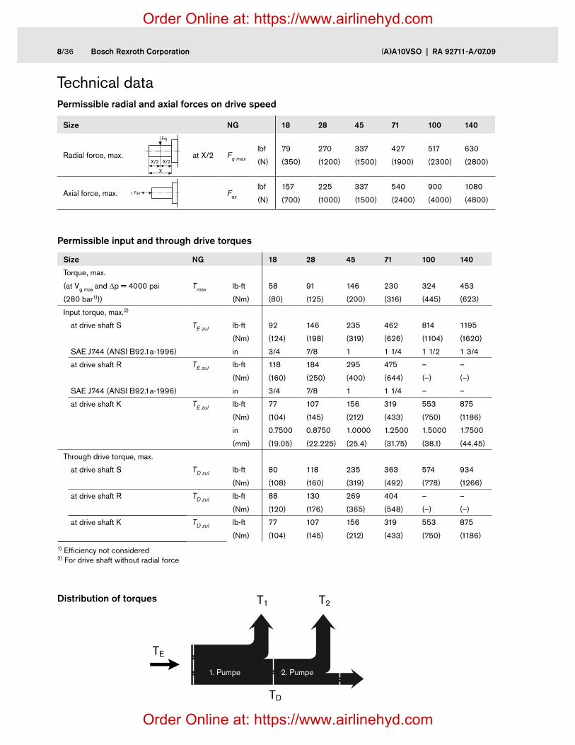
Technical dataPermissible radial and axial forces on drive speed
Size NG 18 28 45 71 100 140
Radial force, max. at X/2 Fq max
lbf
(N)
79
(350)
270
(1200)
337
(1500)
427
(1900)
517
(2300)
630
(2800)
Axial force, max. Fax
lbf
(N)
157
(700)
225
(1000)
337
(1500)
540
(2400)
900
(4000)
1080
(4800)
Fq
X
X/2 X/2
± Fax
Permissible input and through drive torques
Size NG 18 28 45 71 100 140
Torque, max.
(at Vg max and Dp = 4000 psi
(280 bar1)))
Tmax
lb-ft
(Nm)
58
(80)
91
(125)
146
(200)
230
(316)
324
(445)
453
(623)
Input torque, max.2)
at drive shaft S TE zul lb-ft
(Nm)
92
(124)
146
(198)
235
(319)
462
(626)
814
(1104)
1195
(1620)
SAE J744 (ANSI B92.1a-1996) in 3/4 7/8 1 1 1/4 1 1/2 1 3/4
at drive shaft R TE zul lb-ft
(Nm)
118
(160)
184
(250)
295
(400)
475
(644)
–
(–)
–
(–)
SAE J744 (ANSI B92.1a-1996) in 3/4 7/8 1 1 1/4 – –
at drive shaft K TE zul lb-ft
(Nm)
77
(104)
107
(145)
156
(212)
319
(433)
553
(750)
875
(1186)
in
(mm)
0.7500
(19.05)
0.8750
(22.225)
1.0000
(25.4)
1.2500
(31.75)
1.5000
(38.1)
1.7500
(44.45)
Through drive torque, max.
at drive shaft S TD zul lb-ft
(Nm)
80
(108)
118
(160)
235
(319)
363
(492)
574
(778)
934
(1266)
at drive shaft R TD zul lb-ft
(Nm)
88
(120)
130
(176)
269
(365)
404
(548)
–
(–)
–
(–)
at drive shaft K TD zul lb-ft
(Nm)
77
(104)
107
(145)
156
(212)
319
(433)
553
(750)
875
(1186)
1) Efficiency not considered 2) For drive shaft without radial force
Distribution of torques
2. Pumpe1. Pumpe
TE
TD
T1 T2
1. Pumpe 2. Pumpe
Order Online at: https://www.airlinehyd.com
Order Online at: https://www.airlinehyd.com

RA 92711-A/07.09 | (A)A10VSO Bosch Rexroth Corporation 9/36
Operating curves for pumps with pressure controlDrive power and flow(Fluid: mineral fluid to ISO VG 46 DIN 51519, t = 122 °F (50 °C)
Size 18
n = 1800 rpm
n = 3300 rpm
Size 100
n = 1800 rpm
n = 2000 rpm
Size 140
n = 1800 rpm
Size 28
n = 1800 rpm
n = 3000 rpm
Size 45
n = 1800 rpm
n = 2600 rpm
Size 71
n = 1800 rpm
n = 2200 rpm
Operating pressure p
Operating pressure p
Operating pressure p
Operating pressure p
Operating pressure p
Operating pressure p
Flow
qV
Flow
qV
Flow
qV
Driv
e po
wer
P
Driv
e po
wer
PD
rive
pow
er P
Driv
e po
wer
PD
rive
pow
er P
Driv
e po
wer
P
Flow
qV
Flow
qV
Flow
qV
20
10
0
(60)
(40)
(20)
(80)
gpm(L/min)
(280)(250)(200)(150)(100)(50)0
40003500250015001000500 2000 3000
(bar)
psi 0
(30)
(20)
(10)
(40)
HP(kW)
20
40qv Pqv max
Pqv zero
20
10
0
(60)
(40)
(20)
(80)
gpm(L/min)
(280)(250)(200)(150)(100)(50)0
40003500250015001000500 2000 3000
(bar)
psi 0
(30)
(20)
(10)
(40)
HP(kW)60
20
40qv Pqv max
Pqv zero
(280)(250)(200)(150)(100)(50)0
40003500250015001000500 2000 3000
(bar)
psi
20
10
0
(60)
(40)
(20)
(80)
gpm(L/min)
30(100)
(120)
0
(30)
(20)
(10)
(40)
HP(kW)
(50)
(60) 80
40
60
20
qv
Pqv max
Pqv zero
(280)(250)(200)(150)(100)(50)0
40003500250015001000500 2000 3000
(bar)
psi
20
10
0
(60)
(40)
(20)
(80)
gpm(L/min)
30(100)
(120)
40(140)
(160)
0
(30)
(20)
(10)
(40)
HP(kW)
(50)
(60)
(70)
(80)100
40
20
60
80
qv
Pqv max
Pqv zero
(280)(250)(200)(150)(100)(50)0
40003500250015001000500 2000 3000
(bar)
psi
20
10
0
(60)
(40)
(20)
(80)
gpm(L/min)
30(100)
(120)
40(140)
(160)
50(180)
(200)
0
(30)
(20)
(10)
(40)
HP(kW)
(50)
(60)
(70)
(80)
(90)
(100)
40
20
60
80
100
120
qv
Pqv max
Pqv zero
(280)(250)(200)(150)(100)(50)0
40003500250015001000500 2000 3000
(bar)
psi
20
10
0
(60)
(40)
(20)
(80)
gpm(L/min)
30(100)
(120)
40(140)
(160)
50(180)
(200)
60(220)
(240)
(260)
0
20
(30)
(20)
(10)
(40)60
(50)
(60)
(70)
(80)
(90)
(100)
HP(kW)
(110)
(120)
(130)
120
140
160
100
80
40
qv
Pqv max
Pqv zero
Order Online at: https://www.airlinehyd.com
Order Online at: https://www.airlinehyd.com

10/36 Bosch Rexroth Corporation (A)A10VSO | RA 92711-A/07.09
DG – Two point, direct control
Ports
B Outlet portS Inlet portL, L1 Case drain port (L1 plugged)X Pilot pressure port (plugged)
X
L B
SL1
0 4000(280)
725(50)
1020(70)
2040(140)
3060(210)
1740 (120)
1455 (100)
725 (50)
psi (bar)
psi (bar)
Req
. con
trol
pre
ssur
e p st
Operating pressure pB
Schematic DGThe pump can be set to a minimum swivel angle by connecting an external control pressure to port X.
This will supply control fluid directly to the stroking piston; a minimum pressure of pst ≥ 725 psi (50 bar) is required.
The pump can only be switched between Vg max or Vg min.
Please note, that the required control pressure at port X is directly dependent on the actual operating pressure pB in port B (see control pressure diagram).
Control pressure pst in X = 0 psi (0 bar) Vg max
Control pressure pst in X ≥ 725 psi (50 bar) Vg min
The max. permissible control pressure is pst = 1740 psi (120 bar).
Control pressure diagram
Order Online at: https://www.airlinehyd.com
Order Online at: https://www.airlinehyd.com

RA 92711-A/07.09 | (A)A10VSO Bosch Rexroth Corporation 11/36
DR – Pressure control
Ports
B Outlet portS Inlet portL, L1 Case drain port (L1 plugged)
Controller data
Hysteresis and repetitive accuracy Dp____ max. 45 psi (3 bar)
Pressure increase, max
NG 18 28 45 71 100 140
Dp psi 60 60 90 115 145 175
(bar) (4) (4) (6) (8) (10) (12)
Maximum pilot fluid consumption _______of 0.8 gpm (3 L/min)
Flow loss at qVmax see page 9.
(35)
(280)4000
510
(bar)psi
Flow qv [gpm (L/min)]
oper
atin
g pr
essu
re p
B
Hys
tere
sis
and
pres
sure
rise
Dp m
ax
Set
ting
rang
e
L B
SL1
Schematic DR size 18 up to 100
Size 140
The DR-pressure control limits the maximum pressure at the pump outlet within the pump‘s control range. The pump therefore supplies only the amount of fluid as required by the actuators. This maximum pressure level can be set steplessly at the control valve.
Static characteristic
at n1 = 1500 rpm; tfluid = 122 °F (50 °C)
Order Online at: https://www.airlinehyd.com
Order Online at: https://www.airlinehyd.com

12/36 Bosch Rexroth Corporation (A)A10VSO | RA 92711-A/07.09
Ports
B Outlet portS Inlet portL, L1 Case drain port (L1 plugged)X Pilot pressure port
Controller data
Hysteresis and repetitive accuracy Dp____ max. 45 psi (3 bar)
Pressure increase, max
NG 18 28 45 71 100 140
Dp psi 60 60 90 115 145 175
(bar) (4) (4) (6) (8) (10) (12)
Maximum pilot fluid consumption _______of 0.8 gpm (3 L/min)
Flow loss at qVmax see page 9.
not included in supply
not included in supply
DRG – Pressure control, remoteSchematic DRG size 18 up to 100The DR-pressure control (see page 11) is overriding this DRG-
remote setting of max. outlet pressure.
A pressure relief valve can be externally piped to port X for remote setting of pressure below the setting of the DR control valve spool. This relief valve is not included in the pump supply.
The differential pressure at the DRG-control spool is set as standard to 290 psi (20 bar). This results in a pilot fluid flow to the relief valve of approx. 0.4 gpm (1,5 L/min) at port X. If another setting is required (range from 145 and 320 psi (10 to 22 bar)) please state in clear text.
As a separate relief valve we can recommend:
DBDH 6 (hydraulic) to RE 25402 or
DBETR-SO 381 with orifice dia. 0.03 inch (0,8 mm) in P (elec-tric) to RE 29166.
The max. lenght of piping should not exceed 6.6 ft (2 m).
Static characteristic
at n1 = 1500 rpm; tfluid = 122 °F (50 °C)
L B
SL1
X
X
20
280
290
4000(bar)psi
Flow qv [gpm (L/min)]
oper
atin
g pr
essu
re p
B
Hys
tere
sis
and
pres
sure
rise
Dp m
ax
Set
ting
rang
e
Size 140
Order Online at: https://www.airlinehyd.com
Order Online at: https://www.airlinehyd.com
RA 92711-A/07.09 | (A)A10VSO Bosch Rexroth Corporation 13/36
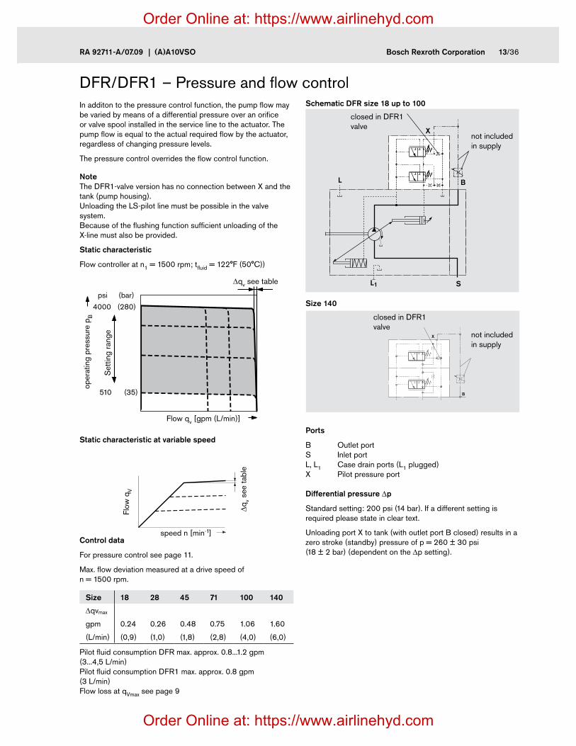
In additon to the pressure control function, the pump flow may be varied by means of a differential pressure over an orifice or valve spool installed in the service line to the actuator. The pump flow is equal to the actual required flow by the actuator, regardless of changing pressure levels.
The pressure control overrides the flow control function.
Note The DFR1-valve version has no connection between X and the tank (pump housing). Unloading the LS-pilot line must be possible in the valve system. Because of the flushing function sufficient unloading of the X-line must also be provided.
Static characteristic
Flow controller at n1 = 1500 rpm; tfluid = 122°F (50°C))
Static characteristic at variable speed
X
L B
SL1
closed in DFR1 valve
closed in DFR1 valve
not included in supply
not included in supply
DFR/DFR1 – Pressure and flow controlSchematic DFR size 18 up to 100
X
B
Size 140
(35)
(280)
510
4000
(bar)psi
Flow qv [gpm (L/min)]
oper
atin
g pr
essu
re p
B
Dqv see table
Set
ting
rang
e
Ports
B Outlet port S Inlet port L, L1 Case drain ports (L1 plugged) X Pilot pressure port
Differential pressure Dp
Standard setting: 200 psi (14 bar). If a different setting is required please state in clear text.
Unloading port X to tank (with outlet port B closed) results in a zero stroke (standby) pressure of p = 260 ± 30 psi (18 ± 2 bar) (dependent on the Dp setting).
Control data
For pressure control see page 11.
Max. flow deviation measured at a drive speed of n = 1500 rpm.
Size 18 28 45 71 100 140
Dqvmax
gpm
(L/min)
0.24
(0,9)
0.26
(1,0)
0.48
(1,8)
0.75
(2,8)
1.06
(4,0)
1.60
(6,0)
Pilot fluid consumption DFR max. approx. 0.8...1.2 gpm (3...4,5 L/min) Pilot fluid consumption DFR1 max. approx. 0.8 gpm (3 L/min) Flow loss at qVmax see page 9
Flow
qV
Dqv s
ee ta
ble
speed n [min-1]
Order Online at: https://www.airlinehyd.com
Order Online at: https://www.airlinehyd.com

14/36 Bosch Rexroth Corporation (A)A10VSO | RA 92711-A/07.09
DFLR – Pressure-flow-power controlIn order to achieve a constant drive torque with a varying operating pressure, the swivel angle and with it the output flow from the axial piston unit is varied so that the product of flow and pressure remains constant.
Flow control is posssible below the limit of the power curve.
Static characteristic
at 1800 rpm
The power characteristic is set at the factory, please state your requierements in clear text e.g. 27 HP (20 kW) at 1800 rpm.
Control data
For technical data constant pressure control see page 11. For technical data flow control see page 13.
Start of control ________________ from up to 735 psi (50 bar) and above 3480 psi (240 bar) Pilot fluid consumption ___ max. approx. 1.45 gpm (5,5 L/min)
Flow loss at qmax see page 9.
not included in supply
not included in supply
Ports
B Outlet port S Inlet port L, L1 Case drain port (L1 plugged) X Pilot pressure port
Schematic DFLR Size 28 up to 100
Size 140
X
L B
SL1
X
L B
SL1
0 100
(0)
(50)
(100)
(150)
(200)
(250)
(280)(300)
0
725
1450
2200
2900
3600
40004350
0 100
∆qV
Maximum power curve
Minimum power curveO
pera
ting
pres
sure
p [
psi (
bar)
]To
rque
T [
Nm
]
Flow qv [%]
Order Online at: https://www.airlinehyd.com
Order Online at: https://www.airlinehyd.com

RA 92711-A/07.09 | (A)A10VSO Bosch Rexroth Corporation 15/36
Notes
Order Online at: https://www.airlinehyd.com
Order Online at: https://www.airlinehyd.com
16/36 Bosch Rexroth Corporation (A)A10VSO | RA 92711-A/07.09
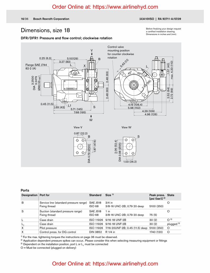
Dimensions, size 18DFR/DFR1 Pressure and flow control; clockwise rotation
Before finalizing your design request a certified installation drawing. Dimensions in inches and (mm).
Ports Designation Port for Standard Size 1) Peak press.
[psi (bar)] 2)State
B Service line (standard pressure range) Fixing thread
SAE J518 ISO 68
3/4 in 3/8-16 UNC-2B; 0.79 20 deep
5100 (350)
O
S Suction (standard pressure range) Fixing thread
SAE J518 ISO 68
1 in 3/8-16 UNC-2B; 0.79 20 deep
75 (5)
O
L Case drain ISO 11926 9/16-18 UNF-2B 30 (2) O 3)
L1 Case drain ISO 11926 9/16-18 UNF-2B 30 (2) plugged 3)
X Pilot pressure ISO 11926 7/16-20UNF-2B; 0.45 (11.5) deep 5100 (350) OX Control press. for DG control DIN 3852 R 1/4 in 1740 (120) O
1) For the max. tightening torques the instructions on page 36 must be observed. 2) Application dependent pressure spikes can occur.. Please consider this when selecting measuring equipment or fittings 3) Dependent on the installation position, port L or L1 must be connected O = Must be connected (plugged on delivery)
7.68 (195)
2.48
(63
)2.
48 (6
3)
W
V
5.71 (145)
XL
L1
5.10(129)
1.69 (43)
(Ø82
.55
)
3.25
003.
2479
DIA
h8
0.25 (6.3)3.27 (83)
0.45 (11.5)
2.06
(52.
4)
1.03 (26.2)
S
S
DIA
0.9
8 (Ø
25)
1.87
(47.
6)
DIA
0.7
9 (Ø
20)
B
B
0.87 (22.2)
L
4.96 (126)
1.57
(40
)
5.98 (152)
2.60 (66)
0.43 (11)
4.29 (109)
max
. 4.3
3 (1
10)
2.52
(64)
2.72
(69
)
4.19 (106.4)
45°45°
X
View V
Flange SAE J744 82-2 (A)
View W
Control valve mounting position for counter clockwise rotation
Order Online at: https://www.airlinehyd.com
Order Online at: https://www.airlinehyd.com
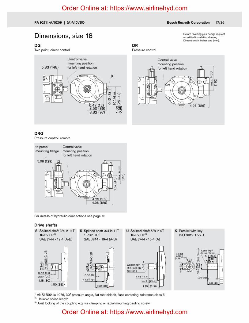
RA 92711-A/07.09 | (A)A10VSO Bosch Rexroth Corporation 17/36
Dimensions, size 18
S Splined shaft 3/4 in 11T 16/32 DP1)
SAE J744 - 19-4 (A-B)
K Parallel with key ISO 3019-1 22-1
U Splined shaft 5/8 in 9T 16/32 DP1)
SAE J744 - 16-4 (A)
R Splined shaft 3/4 in 11T 16/32 DP1)
SAE J744 - 19-4 (A-B)
Before finalizing your design request a certified installation drawing. Dimensions in inches and (mm).
Drive shafts
DRG Pressure control, remote
DR Pressure control
DG Two point, direct control
For details of hydraulic connections see page 16
1) ANSI B92.1a-1976, 30° pressure angle, flat root side fit, flank centering, tolerance class 5 2) Usuable spline length 3) Axial locking of the coupling e.g. via clamping or radial mounting binding screw
0.55 (14)
0.832) (21)
1.50 (38)
ø3/4
in
1/4-
20U
NC
-2B
1.50 (38)1.18 (30)0.87 (22)0.55 (14)
1/4-
20U
NC
-2B
Ø3
/4in
ø 5/
8 in
0.62 (15.8)
Centering3)
R 0.12x0.26DIN 332
0.94 (23.8)
1.25 (31.8)
0.75
00 (Ø
19.0
5–0
.02)
0.74
92
0.10(2.5)
1.30 (33)
1.61 (41)
0.83
(21.1
)
(4.76+0.025 )
0.18840.1874 1.13 (28.6)
DIA
Centering3)
R3.15x6.7 DIN332
0.12
(3)
R 1
/4 in
(25
)
0.98
1.00
+0.
4
3.50 (89)0.47 (12)
3.82 (97)
X
5.83 (148)
Control valve mounting position for left hand rotation
Control valve mounting position for left hand rotation
to pump mounting flange
Control valve mounting position for left hand rotation
4.96 (126)
max
. 4.3
3(1
10)X
X
5.08 (129)
4.96 (126)
1.57
(40
)
4.29 (109)
max
. 4.3
3(1
10)X
Order Online at: https://www.airlinehyd.com
Order Online at: https://www.airlinehyd.com

18/36 Bosch Rexroth Corporation (A)A10VSO | RA 92711-A/07.09
Dimensions, size 28DFR/DFR1 Pressure and flow control; clockwise rotation
S Splined shaft 7/8 in 13T 16/32 DP4)
SAE J744 - 22-4 (B)R Splined shaft 7/8 in 13T 16/32 DP4)
SAE J744 - 22-4 (B)
Drive shaft
Ports Designation Port for Standard Size 1) Peak press.
[psi (bar)] 2)State
B Service line (standard pressure range) Fixing thread
SAE J518 ISO 68
3/4 in 3/8-16 UNC-2B; 0.79 (20) deep
5100 (350)
O
S Inlet (standard pressure range Fixing thread
SAE J518 ISO 68
1 1/4 in 7/16-14 UNC-2B; 0.94 (24) deep
75 (5)
O
L, L1 Case drain (L1 plugged) ISO 11926 3/4-16 UNF-2B; 0.47 (12) deep 30 (2) O 3)
X Pilot pressure ISO 11926 7/16-14UNC-2B; 0.47 (12) deep 5100 (350) OX Control pressure for DG control DIN 3852 R 1/4 in 1740 (120) O
1) For the max. tightening torques the instructions on page 36 must be observed. 2) Application dependent pressure spikes can occur.. Please consider this when selecting measuring equipment or fittings 3) Dependent on the installation position, port L or L1 must be connected O = Must be connected (plugged on delivery)
K Parallel with key ISO 3019-1 22-1
4) ANSI B92.1a-1976, 30° pressure angle, flat base, flank centering, fit class 5
X
S
2.31
(58.
7)D
IA 1
.26
(Ø32
)
1.19(30.2)
B
0.88(22.2)
DIA
0.7
9(Ø
20)
1.88
(47
.6)
(Ø10
1,6
)
3.99
794.
0000
DIA
h8
3.15
(80
)3.
15 (
80)
8.11 (206)
0.55 (14)1.57 (40)
XL L
L16.46 (164)
0.25 (6.3)0.37 (9.5)
W
V
3.54 (90)5.47 (139)
5.35 (136)4.67 (119)
6.85 (74)
3.29 (83.5)
5.75 (146)6.46 (164)
max
. 4.3
3 (1
10)
1.57
(40
)2.
91 (7
4)
DIA 0
.55 (14)
45°45°6.85(Ø174)
S
B
View V
Flange SAE J744 101-2 (B)
View W
Control valve mounting position for counter clockwise rotation
0.98
3 (2
5
)0.
984
(6.35+0.025
-0.0
15
)
0.25100.2500
0.63 (16)
0.98 (25)
1.61 (41)
ø7/8
in1/
4-20
UN
C-2
B
Usable spline length
1.61 (41)1.30 (33.1)0.99 (25.1)0.63 (16)
1/4-
20U
NC
-2B
Ø7/
8 in
Before finalizing your design request a certified installation drawing. Dimensions in inches and (mm).
Order Online at: https://www.airlinehyd.com
Order Online at: https://www.airlinehyd.com
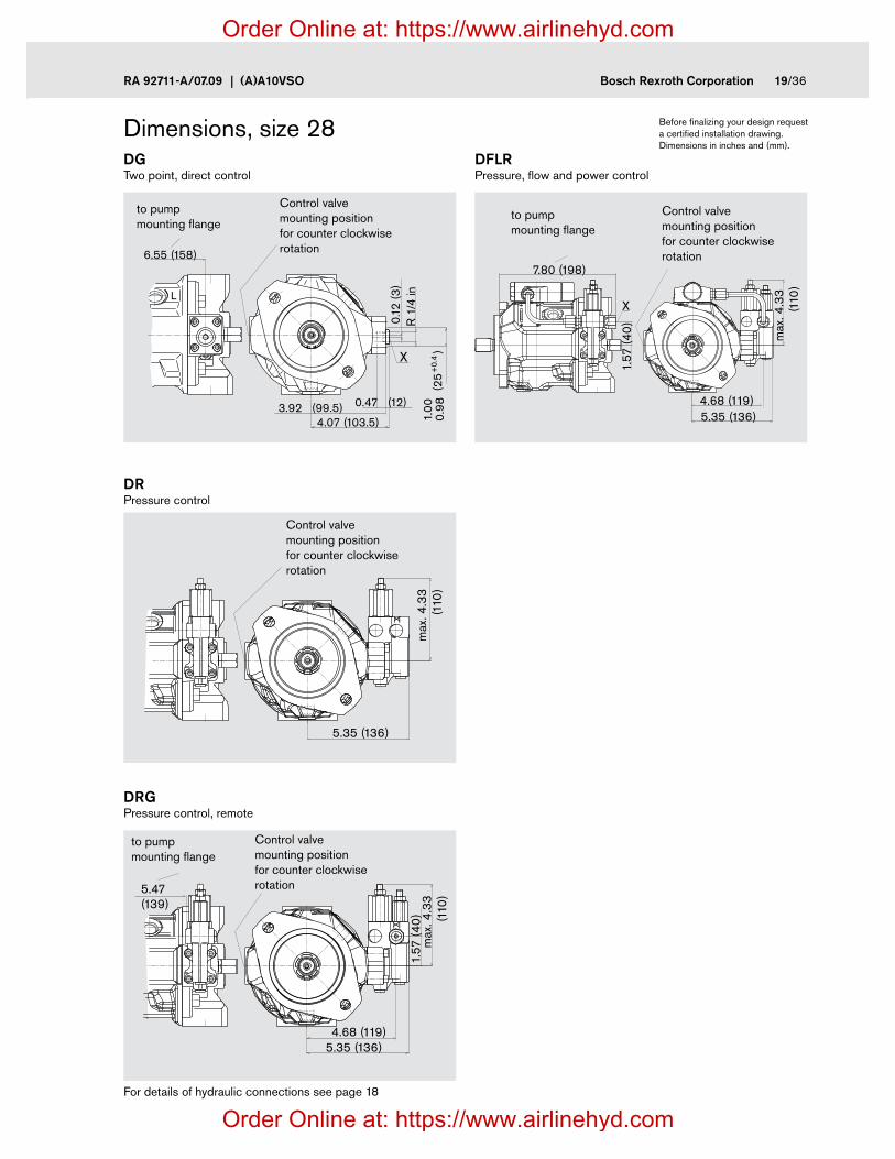
RA 92711-A/07.09 | (A)A10VSO Bosch Rexroth Corporation 19/36
5.35 (136)4.68 (119)
max
. 4.3
3 (1
10)
1.57
(40
)
7.80 (198)
X
Dimensions, size 28
DRG Pressure control, remote
DR Pressure control
DG Two point, direct control
DFLR Pressure, flow and power control
For details of hydraulic connections see page 18
Control valve mounting position for counter clockwise rotation
Control valve mounting position for counter clockwise rotation
Control valve mounting position for counter clockwise rotation
Control valve mounting position for counter clockwise rotation
to pump mounting flange
to pump mounting flange
to pump mounting flange
L
0.12
(3)
R 1
/4 in
(25
)
0.98
1.00
+0.
4
3.92 (99.5)4.07 (103.5)
0.47 (12)
X
6.55 (158)
X
5.35 (136)
max
. 4.3
3(1
10)
X
5.47(139)
5.35 (136)4.68 (119)
max
. 4.3
3(1
10)
1.57
(40
)
Before finalizing your design request a certified installation drawing. Dimensions in inches and (mm).
Order Online at: https://www.airlinehyd.com
Order Online at: https://www.airlinehyd.com

20/36 Bosch Rexroth Corporation (A)A10VSO | RA 92711-A/07.09
Dimensions, size 45DFR/DFR1 Pressure and flow control; clockwise rotation
Before finalizing your design request a certified installation drawing. Dimensions in inches and (mm).
Ports Designation Port for Standard Size 1) Peak press.
[bar] 2)State
B Service line (standard pressure range) Fixing thread
SAE J518 ISO 68
1 in 3/8-16 UNC-2B; 0.71 (18) deep
5100 (350)
O
S Inlet (standardpressure range) Fixing thread
SAE J518 ISO 68
1 1/2 in 1/2-13 UNC-2B; 0.87 (22) deep
75 (5)
O
L Case drain ISO 11926 7/8-14 UNF-2B 30 (2) O 3)
L1 Case drain ISO 11926 7/8-14 UNF-2B 30 (2) plugged 3)
X Pilot pressure ISO 11926 7/16-20 UNF-2B; 0.45 (11,5) deep 5100 (350) OX Control pressure for DG control DIN 3852 R 1/4 in 1740 (120) O
1) For the max. tightening torques the instructions on page 36 must be observed. 2) Application dependent pressure spikes can occur.. Please consider this when selecting measuring equipment or fittings 3) Dependent on the installation position, port L or L1 must be connected O = Must be connected (plugged on delivery)
W
V
X
1.41 (35.7)
1.57
(Ø40
)2.
75 (6
9.9
) S
B
DIA
0.9
8 (Ø
25)
2.06
(52.
4)1.03 (26.2)
5.08 (129)5.75 (146)
6.02 (153)
3.54
(90
)3.
54 (9
0)
max
. 4.3
3 (1
10)
1.57
(40
)
5.75 (146)
0.37 (9.5)
LL
X
L1
(Ø10
1.6
)
DIA
3.99
794.
0000
h8
8.62 (219)8.82 (224)
7.25 (184)
3.78 (96)0.25 (6.3)
7.24 (184)1.77 (45)
0.56 (14.3)
3.17
(80.
5)
3.68 (93.5)
DIA 0
.55
(Ø14
)
3.27 (8
3)
45°45°
View V
Flange SAE J744 101-2 (B)
View W
Control valve mounting position for counter clockwise rotation
Order Online at: https://www.airlinehyd.com
Order Online at: https://www.airlinehyd.com

RA 92711-A/07.09 | (A)A10VSO Bosch Rexroth Corporation 21/36
0.63 (16)
1.16 (29.5)
1.81 (45.9)
ø1in
1/4-
20U
NC
-2B
Dimensions, size 45
DRG Pressure control, remote
DR Pressure control
DG Two point, direct control
DFLR Pressure, flow and power control
Control valve mounting position for counter clockwise rotation
Control valve mounting position for counter clockwise rotation
Control valve mounting position for counter clockwise rotation
Control valve mounting position for counter clockwise rotation
to pump mounting flange
to pump mounting flange
to pump mounting flange
Before finalizing your design request a certified installation drawing. Dimensions in inches and (mm).
S Splined shaft 1 in 15T 16/32 DP4)
SAE J744 - 25-4 (B-B)
R Splined shaft 1 in 15T 16/32 DP4)
SAE J744 - 25-4 (B-B)
U Splined shaft 7/8 in 13T 16/32 DP4)
SAE J744 - 22-4 (B)
K Parallel with key ISO 3019-1 25-1
Usable spline length1.81 (45.9)
1.50 (38)1.18 (30)
0.63 (16)
1/4-
20U
NC
-2B
Ø1
in
0.63 (16)
0.99 (25.1)
ø7/8
in1/
4-20
UN
C-2
B
1.61 (41)
Drive shaft
4) ANSI B92.1a-1976, 30° pressure angle, flat base, flank centering, fit class 5
1.102
(28.
2 -0
.2)
1.110
(6.35+0.025 )
0.2510.250
R 1
/4 in
(25
)0.
981.
00+
0.4
6.81 (173)
4.33 (110)4.61 (117)
X
0.12
(3)
0.47 (12)X
5.75 (146)
max
. 4.3
3 (1
10)
1.57
(40
)
5.10 (129)
X
8.23 (209)
5.75 (146)
4.41
(1
12)
X
5.08 (129)5.75 (146)
6.02 (153)
max
. 4.3
3 (1
10)
1.57
(40
)
X
Order Online at: https://www.airlinehyd.com
Order Online at: https://www.airlinehyd.com

22/36 Bosch Rexroth Corporation (A)A10VSO | RA 92711-A/07.09
Dimensions, size 71DFR/DFR1 Pressure and flow control; clockwise rotation
Before finalizing your design request a certified installation drawing. Dimensions in inches and (mm).
Ports Designation Port for Standard Size 1) Peak press.
[psi (bar)] 2)State
B Service line (standard pressure range) Fixing thread
SAE J518 ISO 68
1 in 3/8-16 UNC-2B; 0.71 (18) deep
5100 (350)
O
S Inlet (standard pressure range) Fixing thread
SAE J518 ISO 68
2 in 1/2-13 UNC-2B; 0.87 (22) deep
75 (5)
O
L Case drain ISO 11926 7/8-14 UNF-2B 30 (2) O 3)
L1 Case draint ISO 11926 7/8-14 UNF-2B 30 (2) plugged 3)
X Pilot pressure ISO 11926 7/16-20 UNF-2B; 0.45 (11.5) deep 5100 (350) OX Control pressure for DG control DIN 3852 R 1/4 in 1740 (120) O
1) For the max. tightening torques the instructions on page 36 must be observed. 2) Application dependent pressure spikes can occur.. Please consider this when selecting measuring equipment or fittings 3) Dependent on the installation position, port L or L1 must be connected O = Must be connected (plugged on delivery)
L
3.06
(77.
8)
DIA
1.9
7 (Ø
50)
S
1.69 (42.9)
DIA 0.98 (Ø25)
2.06 (52.4)
1.03
(26.
2)
B
10.12 (257)
V
W
3.62
(92)
max
. 4.3
3 (1
10)
5.63 (143)4.23 (107.5)6.30 (160)
1.57
(40
)
2.09 (53)0.71 (18)
(Ø12
7
)h8
4.99
75D
IA5.
0000
0.71 (1
8)3.86 (98)
DIA 7.13 (Ø181)8.27 (210)
L1
L
4.09
(104
)4.
09 (1
04)
7.13 (181)0.24 (6) 4.53 (115)
0.50 (12.7)
45°45°
X
8.54 (217)
X
View V
Flange SAE J744 127-2 (C)
View W
Control valve mounting position for counter clockwise rotation
Order Online at: https://www.airlinehyd.com
Order Online at: https://www.airlinehyd.com
RA 92711-A/07.09 | (A)A10VSO Bosch Rexroth Corporation 23/36
L
max
4.3
3 (1
10)
5.63 (143)6.30 (160)
1.57
(40
)
7.13 (181)X
X
L
9.37 (238)
5.63 (143)6.30 (160)
4.88
(124
)
X
1.57
(40
)
L
7.91 (201)
0.47 (12)0.
12 (3
)R
1/4
in25
0.98
1.00
+0.
4
5.02(127.5)4.86 (123.5)
X
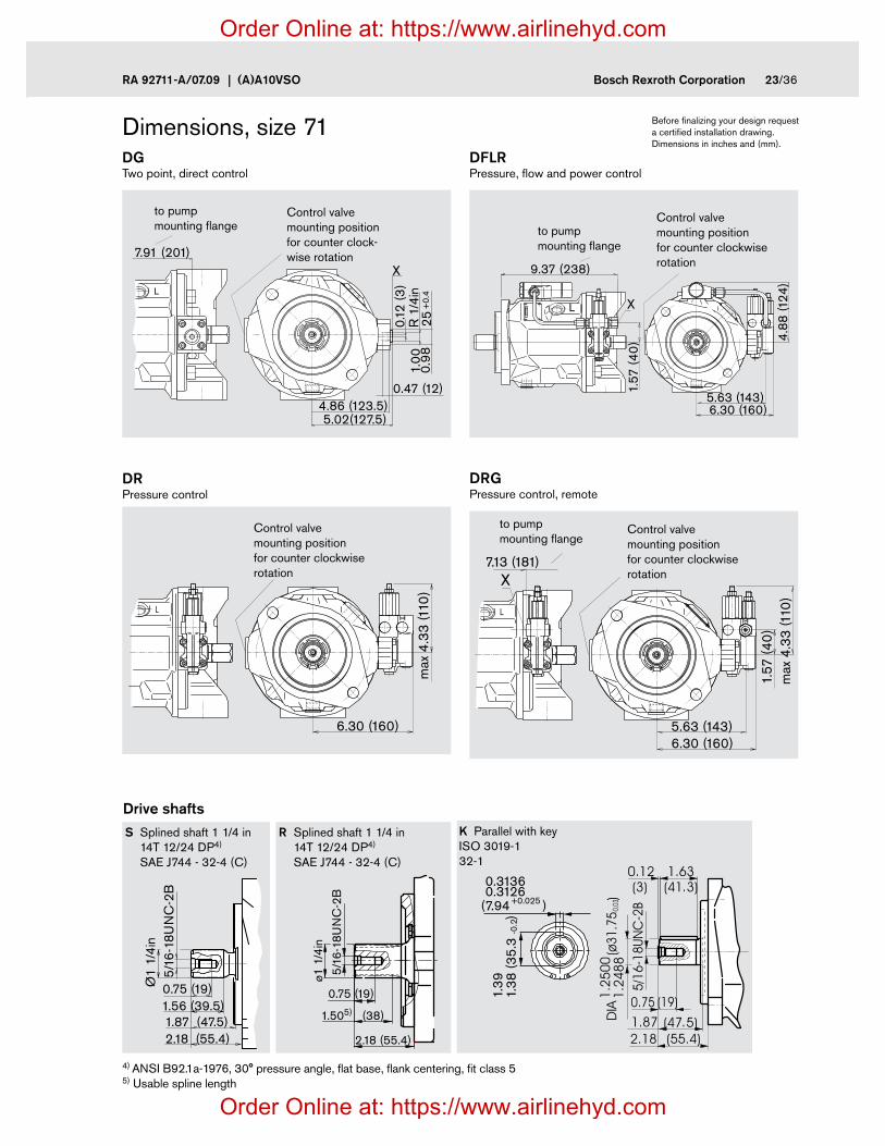
Dimensions, size 71 Before finalizing your design request a certified installation drawing. Dimensions in inches and (mm).
DRG Pressure control, remote
DR Pressure control
DG Two point, direct control
DFLR Pressure, flow and power control
Control valve mounting position for counter clockwise rotation
Control valve mounting position for counter clock-wise rotation
Control valve mounting position for counter clockwise rotation
Control valve mounting position for counter clockwise rotation
to pump mounting flange
to pump mounting flange
to pump mounting flange
Drive shafts
L
max
4.3
3 (1
10)
6.30 (160)
X
S Splined shaft 1 1/4 in 14T 12/24 DP4)
SAE J744 - 32-4 (C)
R Splined shaft 1 1/4 in 14T 12/24 DP4)
SAE J744 - 32-4 (C)
K Parallel with key ISO 3019-1 32-1
0.75 (19)
1.505) (38)
2.18 (55.4)
ø1 1
/4in
5/16
-18U
NC
-2B
2.18 (55.4)1.87 (47.5)1.56 (39.5)0.75 (19)
5/16
-18U
NC
-2B
Ø1
1/4i
n
1.38
(35.
3
)1.
39
(7.94 +0.025
-0.2
)
0.31360.3126
4) ANSI B92.1a-1976, 30° pressure angle, flat base, flank centering, fit class 5 5) Usable spline length
Order Online at: https://www.airlinehyd.com
Order Online at: https://www.airlinehyd.com

24/36 Bosch Rexroth Corporation (A)A10VSO | RA 92711-A/07.09
Dimensions, size 100DFR/DFR1 Pressure and flow control; clockwise rotation
Before finalizing your design request a certified installation drawing. Dimensions in inches and (mm).
X
DIA
1.2
6 (Ø
32)
2.63
(66.
7)
1.25(31.8)
B
S
3.50
(88.
9)
DIA
2.3
6(Ø
60)
2.00(50.8)
1.57
(40
)
5.84 (148.4)6.50 (165)12.48 (317)
12.95 (329)
3.94
(100
)3.9
4 (1
00)
7.09 (180)8.27 (210)
4.65 (118)
0.69
(17.
5)5.
98 (1
52)
4.17 (1
06)
3.74
(95
)
W
VX
L
L1
0.24 (6)9.80 (249)
0.79 (20)3.74 (95)
10.83 (275)
6.89 (175)0.50 (12.7)
max
. 4.3
3 (1
10)
(Ø12
7
)4.
9975
DIA
5.00
00h8
45°View V
Flange SAE J744 127-2 (C)
View W
Control valve mounting position for counter clockwise rotation
Ports Designation Port for Standard Size 1) Peak press.
[psi (bar)] 2)State
B Service line (high pressure range) Fixing thread
SAE J518 ISO 68
1 1/4 in 1/2-13 UNC-2B; 0.75 (19) deep
5100 (350)
O
S Inlet (standard pressure range Fixing thread
SAE J518 ISO 68
2 1/2 in 1/2-13 UNC-2B; 1.06 (27) deep
75 (5)
O
L Case drain ISO 11926 1 1/16-12 UNF-2B 30 (2) O 3)
L1 Case drain ISO 11926 1 1/16-12 UNF-2B 30 (2) plugged 3)
X Pilot pressure ISO 11926 7/16-20 UNF-2B; 0.45 (11.5) deep 5100 (350) OX Control pressure for DG control DIN 3852 R 1/4 in 1740 (120) O
1) For the max. tightening torques the instructions on page 36 must be observed. 2) Application dependent pressure spikes can occur.. Please consider this when selecting measuring equipment or fittings 3) Dependent on the installation position, port L or L1 must be connected O = Must be connected (plugged on delivery)
Order Online at: https://www.airlinehyd.com
Order Online at: https://www.airlinehyd.com
RA 92711-A/07.09 | (A)A10VSO Bosch Rexroth Corporation 25/36
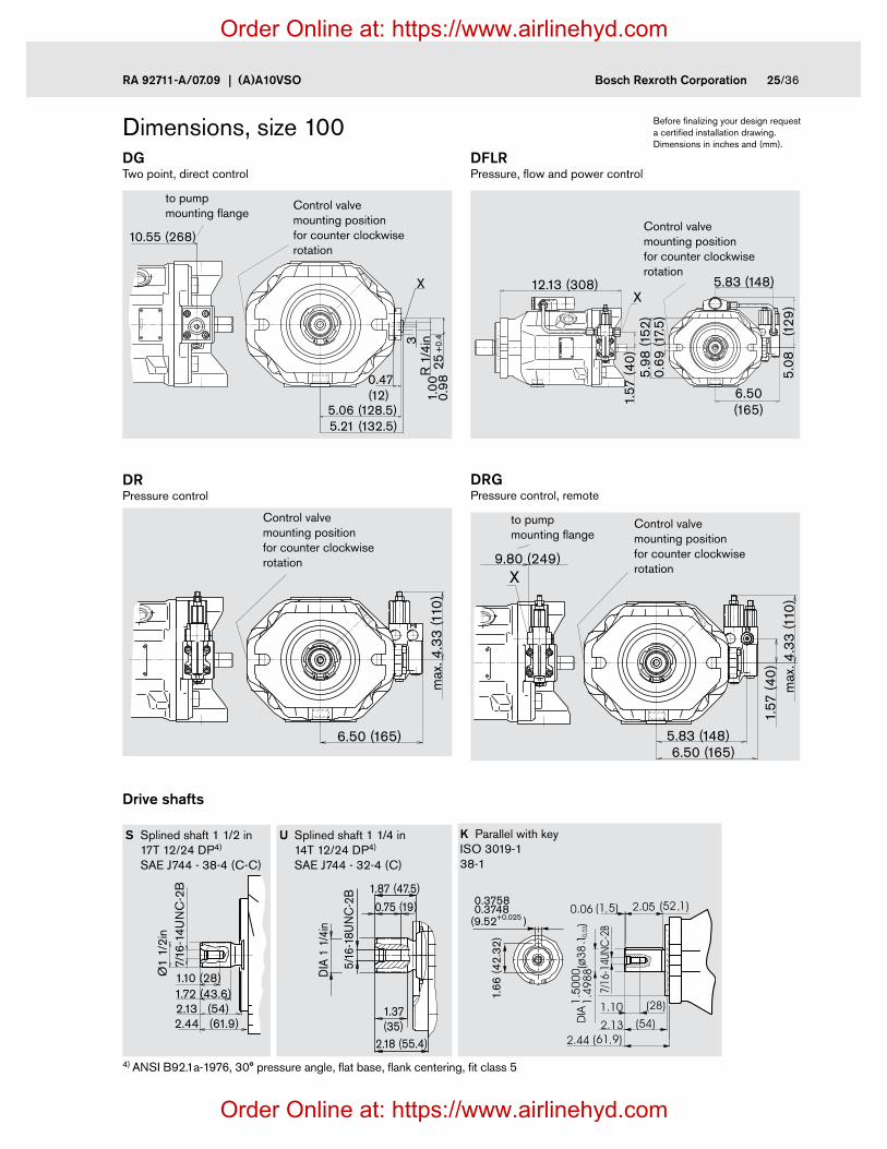
Dimensions, size 100 Before finalizing your design request a certified installation drawing. Dimensions in inches and (mm).
Drive shafts
DRG Pressure control, remote
DR Pressure control
DG Two point, direct control
DFLR Pressure, flow and power control
S Splined shaft 1 1/2 in 17T 12/24 DP4)
SAE J744 - 38-4 (C-C)
U Splined shaft 1 1/4 in 14T 12/24 DP4)
SAE J744 - 32-4 (C)
K Parallel with key ISO 3019-1 38-1
10.55 (268)
0.47(12)
250.
981.
00+
0.4
R 1
/4in3
5.06 (128.5)5.21 (132.5)
X
Control valve mounting position for counter clockwise rotation
Control valve mounting position for counter clockwise rotation
Control valve mounting position for counter clockwise rotation
Control valve mounting position for counter clockwise rotation
to pump mounting flange
to pump mounting flange
X
6.50 (165)
max
. 4.3
3 (1
10)
X
1.57
(40
)
5.83 (148)6.50 (165)
X9.80 (249)
max
. 4.3
3 (1
10)
5.83 (148)
1.57
(40
)
6.50(165)
5.08
(1
29)
0.69
(17.
5)5.
98 (1
52)
X12.13 (308)
1.66
(42.
32)
(9.52+0.025 )
0.37580.3748
2.44 (61.9)2.13 (54)1.72 (43.6)1.10 (28)
7/16
-14U
NC
-2B
Ø1
1/2i
n
DIA
1 1
/4in
2.18 (55.4)
0.75 (19)1.87 (47.5)
5/16
-18U
NC
-2B
1.37(35)
4) ANSI B92.1a-1976, 30° pressure angle, flat base, flank centering, fit class 5
Order Online at: https://www.airlinehyd.com
Order Online at: https://www.airlinehyd.com

26/36 Bosch Rexroth Corporation (A)A10VSO | RA 92711-A/07.09
L
3.50
(88.
9)
2.63
(66.
7)
S
B
DIA
1.2
6 (Ø
32)
1.25 (31.8)
DIA
2.4
8 (Ø
63)
2.00 (50.8)
4.33
(110
)4.3
3 (1
10)
10.83 (275)
6.36
(161
.6)
7.87
(200
)
5.16 (131)
DIA 0.79 (20.6)YV
W
45°
0.83 (21)3.07 (78)
(Ø15
2.4
)
5.99
75D
IA6.
000
0h8
X
L1
L L
13.27 (337)
8.74 (222)
4.67 (1
18.5)
5.00
(127
)
7.20 (183)8.23 (209)
4.41
(112
)1.
06 (2
6)
4.25
(108
)
6.36 (161.6)7.87 (200)
6.81 (173)0.50 (12.7)0.25 (6.4)
Dimensions, size 140DFR/DFR1 Pressure and flow control; clockwise rotation
Before finalizing your design request a certified installation drawing. Dimensions in inches and (mm).
Ports Designation Port for Standard Size 1) Peak press.
[psi (bar)] 2)State
B Service line (high pressure range) Fixing thread
SAE J518 ISO 68
1 1/4 in 1/2-13 UNC-2B; 0.94 (24) deep
5100 (350)
O
S Inlet (standard pressure range) Fixing thread
SAE J518 ISO 68
2 1/2 in 1/2-13 UNC-2B; 0.94 (24) deep
75 (5)
O
L Case drain ISO 11926 1 1/16-12 UNF-2B 30 (2) O 3)
L1 Case drain ISO 11926 1 1/16-12 UNF-2B 30 (2) plugged 3)
X Pilot pressure ISO 11926 9/16-18 UNF-2B; 0.51 (13) deep 5100 (350) OX Pilot pressure for DG control DIN 3852 M14 x 1.5; 0.47 (12) deep 1740 (120) OMH Control pressure for DG control DIN 3852 M14 x 1.5; 0.47 (12) deep 5100 (350) plugged 3)
1) For the max. tightening torques the instructions on page 36 must be observed. 2) Application dependent pressure spikes can occur.. Please consider this when selecting measuring equipment or fittings 3) Dependent on the installation position, port L or L1 must be connected O = Must be connected (plugged on delivery)
View V
Flange SAE J744 152-4 (D)
View W
View YName plate
Control valve mounting position for counter clockwise rotation
Order Online at: https://www.airlinehyd.com
Order Online at: https://www.airlinehyd.com
RA 92711-A/07.09 | (A)A10VSO Bosch Rexroth Corporation 27/36
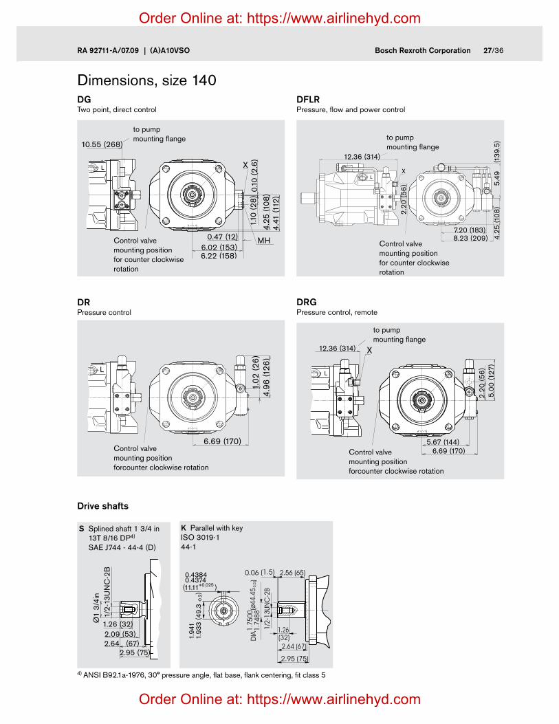
Dimensions, size 140
Drive shafts
DRG Pressure control, remote
DR Pressure control
DG Two point, direct control
DFLR Pressure, flow and power control
S Splined shaft 1 3/4 in 13T 8/16 DP4)
SAE J744 - 44-4 (D)
K Parallel with key ISO 3019-1 44-1
L
4.25
(108
)4.
41 (1
12)
1.10
(28
)6.02 (153)
0.47 (12)
6.22 (158)
MH
X
0.10
(2.6
)
10.55 (268)
L
6.69 (170)
1.02
(26
)4.
96 (1
26)
L
5.00
(127
)2.
20 (5
6)
12.36 (314) X
6.69 (170)5.67 (144)
L
5.49
(1
39.5
)
X
12.36 (314)
4.25
(108
)
2.20
(56
)
7.20 (183)8.23 (209)Control valve
mounting position for counter clockwise rotation
Control valve mounting position forcounter clockwise rotation
Control valve mounting position forcounter clockwise rotation
Control valve mounting position for counter clockwise rotation
to pump mounting flange to pump
mounting flange
to pump mounting flange
2.95 (75)2.64 (67)2.09 (53)1.26 (32)
1/2-
13U
NC
-2B
Ø1
3/4
in
1.93
3 (4
9.3
)
1.94
1
(11.11+0.025
-0.2
)
0.43840.4374
4) ANSI B92.1a-1976, 30° pressure angle, flat base, flank centering, fit class 5
Order Online at: https://www.airlinehyd.com
Order Online at: https://www.airlinehyd.com

28/36 Bosch Rexroth Corporation (A)A10VSO | RA 92711-A/07.09
A4
0.39(10)
(ø10
1.
)
4.00
08D
IA4.
0020
6+
0.05
0+
0.02
0A5(ø146)5.75
A
B
45°
0.65 (16.5)
A2
A1
A5B
45°
DIA 4.19
(ø106.5)
A A4
0.39(10)
0.69 (17.5)
A2
A1
(ø82
.55
)
+0.
050
+0.
020
3.25
08D
IA3.
2520
A4
A1
0.35 (9)
0.39(10)
(ø82
.55
)+
0.05
0+
0.02
0
3.25
08D
IA3.
2520
A5B
45°
DIA 4.19
(ø106.5)
A
Through drive dimensions Before finalizing your design request a certified installation drawing. Dimensions in inches and (mm).
K01 Flange SAE J744 - 82-2 (A) Coupler for splined shaft to ANSI B92.1a-1996 5/8in 9T 16/32 DP1) (SAE J744 - 16-4 (A))
K52 Flange SAE J744 - 82-2 (A) Coupler for splined shaft to ANSI B92.1a-1996 3/4in 11T 16/32 DP1) (SAE J744 - 19-4 (A-B))
K68 Flange SAE J744 - 101-2 (B) Coupler for splined shaft to ANSI B92.1a-1996 7/8in 13T 16/32 DP1) (SAE J744 - 22-4 (B))
Size A1 A4 A5
18 7.16 (182)
1.69 (43)
M10; 0.57 (14.5) deep
28 8.03 (204)
1.85 (47)
M10; 0.62 (16) deep
45 9.02 (229)
2.09 (53)
M10; 0.62 (16) deep
71 10.51 (267)
2.40 (61)
M10; 0.78 (20) deep
100 13.31 (338)
2.56 (65)
M10; 0.78 (20) deep
140 13.78 (350)
0.03 (77)
M10; 0.63 (17) deep
Size A1 A2 A4 A5
18 7.16 (182)
1.54 (39)
1.69 (43)
M10; 0.57 (14.5) deep
28 8.03 (204)
1.54 (39)
1.85 (47)
M10; 0.62 (16) deep
45 9.02 (229)
1.54 (39)
2.09 (53)
M10; 0.62 (16) deep
71 10.51 (267)
1.54 (39)
2.40 (61)
M10; 0.78 (20) deep
100 13.31 (338)
1.54 (39)
2.56 (65)
M10; 0.78 (20) deep
140 13.78 (350)
1.54 (39)
0.03 (77)
M10; 0.63 (17) deep
Size A1 A2 A4 A5
28 8.03 (204)
1.65 (42)
1.85 (47)
M12; through bore
45 9.02 (229)
1.65 (42)
2.09 (53)
M12; 0.71 (18) deep
71 10.51 (267)
1.65 (42)
2.40 (61)
M12; 0.79 (20) deep
100 13.31 (338)
1.65 (42)
2.56 (65)
M12; 0.79 (20) deep
140 13.78 (350)
1.65 (42)
3.03 (77)
M12; 0.79 (20) deep
to pump mounting flange
to pump mounting flange
to pump mounting flange
omitted on size 28
omitted on size 28
1) 30° pressure angle, flat root, side fit, tolerance class 5
Order Online at: https://www.airlinehyd.com
Order Online at: https://www.airlinehyd.com
RA 92711-A/07.09 | (A)A10VSO Bosch Rexroth Corporation 29/36
A5
A
B
45° A4A3
A1
0.51(13)
DIA 7.12
(ø181)
(ø12
7
)
5.00
08D
IA5.
0020
+0.
050
+0.
020
0.51(13)
B
45°
DIA 7.12
(ø181)
(ø12
7
)
5.00
08D
IA5.
0020
+0.
050
+0.
020
0.70(17.9)
A
A2
A4
A1
B
45°
(ø146)5.75
A5
0.71(18)
0.39(10)
(ø10
1.6
)
4.00
08D
IA4.
0020 +0.
050
+0.
020
A
A4
A1
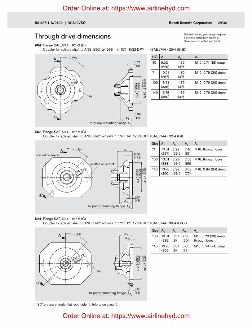
Through drive dimensions Before finalizing your design request a certified installation drawing. Dimensions in inches and (mm).
K04 Flange SAE J744 - 101-2 (B) Coupler for splined shaft to ANSI B92.1a-1996 1in 15T 16/32 DP1) (SAE J744 - 25-4 (B-B))
K07 Flange SAE J744 - 127-2 (C) Coupler for splined shaft to ANSI B92.1a-1996 1 1/4in 14T 12/24 DP1) (SAE J744 - 32-4 (C))
K24 Flange SAE J744 - 127-2 (C) Coupler for splined shaft to ANSI B92.1a-1996 1 1/2in 17T 12/24 DP1) (SAE J744 - 38-4 (C-C))
Size A1 A2 A4 A5
71 10.51 (267)
2.22 (56.5)
2.40 (61)
M16; through bore
100 13.31 (338)
2.22 (56.5)
2.56 (65)
M16; through bore
140 13.78 (350)
2.22 (56.5)
3.03 (77)
M16; 0.94 (24) deep
Size A1 A3 A4 A5
100 13.31 (338)
0.31 (8)
2.56 (65)
M16; 0.79 (20) deep, through bore
140 13.78 (350)
0.31 (8)
3.03 (77)
M16; 0.94 (24) deep
to pump mounting flange
to pump mounting flange
omitted on size 71
omitted on size 71
to pump mounting flange
1) 30° pressure angle, flat root, side fit, tolerance class 5
NG A1 A4 A2
45 9.02 (229)
1.85 (47)
M12; 0.71 (18) deep
71 10.51 (267)
1.85 (47)
M12; 0.79 (20) deep
100 13.31 (338)
1.85 (47)
M12; 0.79 (20) deep
140 13.78 (350)
1.85 (47)
M12; 0.79 (20) deep
Order Online at: https://www.airlinehyd.com
Order Online at: https://www.airlinehyd.com

30/36 Bosch Rexroth Corporation (A)A10VSO | RA 92711-A/07.09
Through drive dimensions Before finalizing your design request a certified installation drawing. Dimensions in inches and (mm).
K17 Flange SAE J744 - 152-4 (D) Coupler for splined shaft to ANSI B92.1a-1996 1 3/4in 13T 8/16 DP1) (SAE J744 - 44-4 (D))
Size A1 A3 A4 A5
140 13.78 (350)
0.31 (8)
3.03 (77)
M16; through bore
1) 30° pressure angle, flat root, side fit, tolerance class 5
0.51(13)
(ø15
2.4
)
6.00
08D
IA6.
0027
+0.
07+
0.02
6.36 (161.6)
6.36
(161
.6)
A
B A5
A4A3
A1to pump mounting flange
Order Online at: https://www.airlinehyd.com
Order Online at: https://www.airlinehyd.com
RA 92711-A/07.09 | (A)A10VSO Bosch Rexroth Corporation 31/36
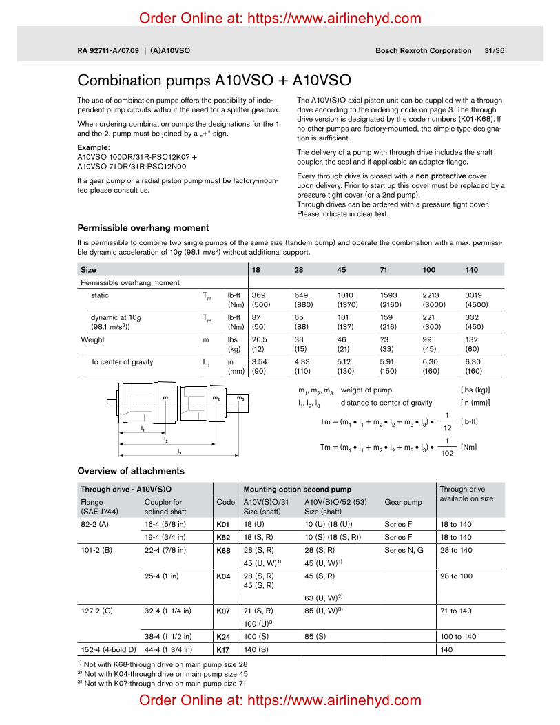
Combination pumps A10VSO + A10VSOThe use of combination pumps offers the possibility of inde-pendent pump circuits without the need for a splitter gearbox.
When ordering combination pumps the designations for the 1. and the 2. pump must be joined by a „+“ sign.
Example: A10VSO 100DR/31R-PSC12K07 + A10VSO 71DR/31R-PSC12N00
If a gear pump or a radial piston pump must be factory-moun-ted please consult us.
The A10V(S)O axial piston unit can be supplied with a through drive according to the ordering code on page 3. The through drive version is designated by the code numbers (K01-K68). If no other pumps are factory-mounted, the simple type designa-tion is sufficient.
The delivery of a pump with through drive includes the shaft coupler, the seal and if applicable an adapter flange.
Every through drive is closed with a non protective cover upon delivery. Prior to start up this cover must be replaced by a pressure tight cover (or a 2nd pump). Through drives can be ordered with a pressure tight cover. Please indicate in clear text.
Permissible overhang momentIt is permissible to combine two single pumps of the same size (tandem pump) and operate the combination with a max. permissi-ble dynamic acceleration of 10g (98.1 m/s2) without additional support.
Size 18 28 45 71 100 140
Permissible overhang moment
static Tm lb-ft (Nm)
369 (500)
649 (880)
1010 (1370)
1593 (2160)
2213 (3000)
3319 (4500)
dynamic at 10g (98.1 m/s2))
Tm lb-ft (Nm)
37 (50)
65 (88)
101 (137)
159 (216)
221 (300)
332 (450)
Weight m lbs (kg)
26.5 (12)
33 (15)
46 (21)
73 (33)
99 (45)
132 (60)
To center of gravity L1 in (mm)
3.54 (90)
4.33 (110)
5.12 (130)
5.91 (150)
6.30 (160)
6.30 (160)
l1
l2
l3
m1 m2 m3
m1, m2, m3 weight of pump [lbs (kg)]
l1, l2, l3 distance to center of gravity [in (mm)]
Tm = (m1 • l1 + m2 • l2 + m3 • l3) •1
[lb-ft]12
Tm = (m1 • l1 + m2 • l2 + m3 • l3) •1
[Nm]102
Overview of attachments
Through drive - A10V(S)O Mounting option second pump Through drive available on sizeFlange
(SAE-J744)Coupler for splined shaft
Code A10V(S)O/31 Size (shaft)
A10V(S)O/52 (53) Size (shaft)
Gear pump
82-2 (A) 16-4 (5/8 in) K01 18 (U) 10 (U) (18 (U)) Series F 18 to 140
19-4 (3/4 in) K52 18 (S, R) 10 (S) (18 (S, R)) Series F 18 to 140
101-2 (B) 22-4 (7/8 in) K68 28 (S, R) 28 (S, R) Series N, G 28 to 140
45 (U, W)1) 45 (U, W)1)
25-4 (1 in) K04 28 (S, R) 45 (S, R)
45 (S, R) 28 to 100
63 (U, W)2)
127-2 (C) 32-4 (1 1/4 in) K07 71 (S, R) 85 (U, W)3) 71 to 140
100 (U)3)
38-4 (1 1/2 in) K24 100 (S) 85 (S) 100 to 140
152-4 (4-bold D) 44-4 (1 3/4 in) K17 140 (S) 140
1) Not with K68-through drive on main pump size 28 2) Not with K04-through drive on main pump size 45 3) Not with K07-through drive on main pump size 71
Order Online at: https://www.airlinehyd.com
Order Online at: https://www.airlinehyd.com
32/36 Bosch Rexroth Corporation (A)A10VSO | RA 92711-A/07.09
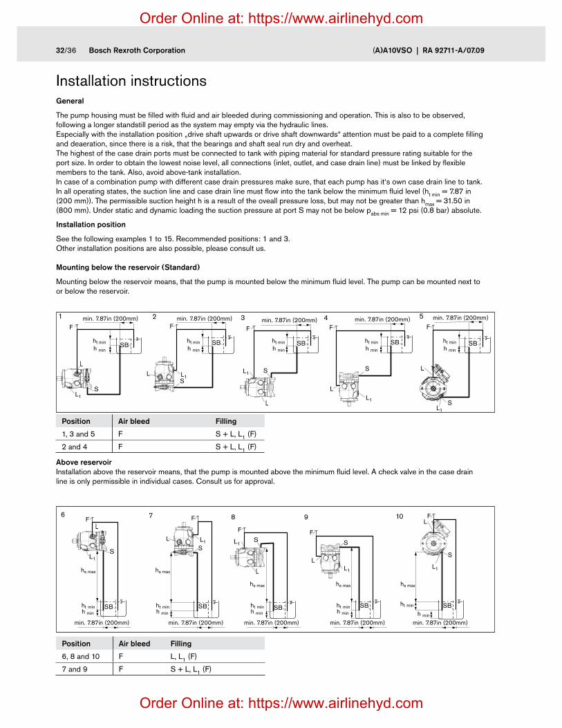
General
The pump housing must be filled with fluid and air bleeded during commissioning and operation. This is also to be observed, following a longer standstill period as the system may empty via the hydraulic lines. Especially with the installation position „drive shaft upwards or drive shaft downwards“ attention must be paid to a complete filling and deaeration, since there is a risk, that the bearings and shaft seal run dry and overheat. The highest of the case drain ports must be connected to tank with piping material for standard pressure rating suitable for the port size. In order to obtain the lowest noise level, all connections (inlet, outlet, and case drain line) must be linked by flexible members to the tank. Also, avoid above-tank installation. In case of a combination pump with different case drain pressures make sure, that each pump has it‘s own case drain line to tank. In all operating states, the suction line and case drain line must flow into the tank below the minimum fluid level (ht min = 7.87 in (200 mm)). The permissible suction height h is a result of the oveall pressure loss, but may not be greater than hmax = 31.50 in (800 mm). Under static and dynamic loading the suction pressure at port S may not be below pabs min = 12 psi (0.8 bar) absolute.
Installation position
See the following examples 1 to 15. Recommended positions: 1 and 3. Other installation positions are also possible, please consult us.
Mounting below the reservoir (Standard)
Mounting below the reservoir means, that the pump is mounted below the minimum fluid level. The pump can be mounted next to or below the reservoir.
Above reservoir Installation above the reservoir means, that the pump is mounted above the minimum fluid level. A check valve in the case drain line is only permissible in individual cases. Consult us for approval.
Position Air bleed Filling
1, 3 and 5 F S + L, L1 (F)
2 and 4 F S + L, L1 (F)
Position Air bleed Filling
6, 8 and 10 F L, L1 (F)
7 and 9 F S + L, L1 (F)
Installation instructions
L
L1S
ht min SB SB
min. 7.87in (200mm)F
1F
L
L1 S
SB
F
3 52
L L1S
SB
F4
LL1
S
SB
F
L
L1S
X
h min
ht min
min. 7.87in (200mm)
h min
ht min
min. 7.87in (200mm)
h min
ht min
min. 7.87in (200mm)
h min
ht min
min. 7.87in (200mm)
h min
L
L1S
F
hs max
ht min
min. 7.87in (200mm)
SB SB
S
F6 7
L L1
L
L1S
F
SB SB
S
F
8 9
LL1
SB
S
F10L
L1
X
h min
hs max
ht min
min. 7.87in (200mm)
h min
hs max
ht min
min. 7.87in (200mm)
h min
hs max
ht min
min. 7.87in (200mm)
h min
hs max
ht min
min. 7.87in (200mm)h min
Order Online at: https://www.airlinehyd.com
Order Online at: https://www.airlinehyd.com

RA 92711-A/07.09 | (A)A10VSO Bosch Rexroth Corporation 33/36
L/L1 = case drain port, F = air bleed or fill port, S = inlet port, SB = baffle (baffle plate), h min = 3.94 in (100 mm), ht min = 7.87 in (200 mm), hS max = 31.50 in (800 mm)
Installation instructionsInside the reservoir
Mounting inside the reservoir. This means that the pump is mounted within the fluid volume.
L
L1S
h t m
in
h min
min. 7.87in (200 mm)
h min
min. 7.87in (200 mm)
h min
min. 7.87in (200 mm)
h min
min. 7.87in (200 mm)
h min
min. 7.87in (200 mm)
SB
11
L
L1 S
h t m
in
SB
13
LL1
S
h t m
inSB
12
LL1
S
h t m
in
SB
14 15
L
L1
S
h t m
in
SB
X
Position Air bleed Filling
11, 13 and 15 L, L1 L, L1
12 and 14 L, L1 S + L, L1
Order Online at: https://www.airlinehyd.com
Order Online at: https://www.airlinehyd.com

34/36 Bosch Rexroth Corporation (A)A10VSO | RA 92711-A/07.09
Notes
Order Online at: https://www.airlinehyd.com
Order Online at: https://www.airlinehyd.com

RA 92711-A/07.09 | (A)A10VSO Bosch Rexroth Corporation 35/36
Notes
Order Online at: https://www.airlinehyd.com
Order Online at: https://www.airlinehyd.com

36/36 Bosch Rexroth Corporation (A)A10VSO | RA 92711-A/07.09
© Bosch Rexroth Corporation
All rights reserved. Neither this document, nor any part of it, may be reproduced, duplicated, circulated or disseminated, whether by copy, electronic format or any other means, without the prior consent and authorization of Bosch Rexroth Corp. The data and illustrations in this brochure/data sheet are intended only to descri-be or depict the products. No representation or warranty, either express or im-plied, relating to merchantability or fitness for intended use, is given or intended by virtue of the information contained in this brochure/data sheet. The information contained in this brochure/data sheet in no way relieves the user of its obligation to insure the proper use of the products for a specific use or application. All products contained in this brochure/data sheet are subject to normal wear and tear from usage. Subject to change.
Bosch Rexroth CorporationAxial & Radial Piston Units8 Southchase CourtFountain Inn, SC 29644-9018 USATelephone (864) 967-2777Facsimile (864) 967-8900www.boschrexroth-us.com
Bosch Rexroth Corporation2315 City Line Road Bethlehem, PA 18017-2131 USATelephone (610) 694-8300Facsimile (610) 694-8467www.boschrexroth-us.com
General instructionThe pump A10VSO was designed for operation in open loop circuits –
Systems design, installation and commissioning requires trained technicians or tradesmen. Be sure to read the entire operating –instructions throughly and completely befor using the axial piston unit. If necessary, request them at Rexroth.
All hydraulic ports can only be used for the fastening of hydraulic service lines. –
During and shortly after operation of a pump the housing and especially a solenoid can be extremely hot, avoid being burned; –take suitable safety measures (wear protective clothing).
Dependent on the operating conditions of the axial piston pump (operating pressure, fluid temperature) deviations in the perfor- –mance curves can occur.
Pressure ports: –All materials and port threads are selected and designed in such a manner, that they can withstand the peak pressures. The machine and system manufacturer must ensure, that all connecting elements and hydraulic lines are suitable for the actual operating pressures.
Pressure cut off and pressure control are not suitable for providing system protection against excessive pressures. A suitable –overall main line relief valve must be incorporated.
All given data and information must be adhered to. –
The following tightening torques are valid: –
- Female threads in the axial piston unit: the maximum permissible tightening torques MGMax are maximum values for the female threads in the pump casting and may not be exceeded. Value see table below.
- Fittings: please comply with the manufacturer‘s information regarding the max. permissible tightening torques for the used fittings.
- Fastening bolts: for fastening bolts to ISO 68 we recommend to check the permissible tightening torques in each individual case to VDI 2230.
- Plugs: for the metal plugs, supplied with the axial piston unit the following min. required tightening torques MV apply (see table).
Thread size in portsMaximum permissible tightening torque MG max
Min. required tightening torque MV
Across the flats in Allan screw
R 1/4 in DIN 3852 48 lb-ft (70 Nm)
7/8-14 UNF-2B ISO 11926 174 lb-ft (240 Nm) 93 lb-ft (127 Nm) 3/8 in
1 1/16-12 UNF-2B ISO 11926 261 lb-ft (360 Nm) 108 lb-ft (147 Nm) 9/16 in
7/16-20UNF-2B ISO 11926 29 lb-ft (40 Nm) 11 lb-ft (15 Nm) 3/16 in
9/16-18 UNF-2B ISO 11926 59 lb-ft (80 Nm) 18 lb-ft (25 Nm) 1/4 in
3/4-16 UNF-2B ISO 11926 118 lb-ft (160 Nm) 45 lb-ft (62 Nm) 5/16in
Order Online at: https://www.airlinehyd.com
Order Online at: https://www.airlinehyd.com