axial piston variable pump a7vk series 10 metering pump
TRANSCRIPT
RE 94010/04.2013, Bosch Rexroth AG
Features ▶ Compact design ▶ Reduced dimensions and mass in comparison to A2VK ▶ Mounting flange, drive shaft and functions identical to
A2VK, thus easy to replace ▶ Increased corrosion protection through special surface
treatment ▶ Manual adjustment with prescision display and clamp
unit to prevent accidental adjustment ▶ Double shaft sealing made of special material and
flushing chamber to identify damage and protect envi-ronment
▶ Improved volumetric efficiency through robust rotary group using proven axial tapered piston technology
▶ Optionally available with mounted high-pressure relief valve
▶ Low noise level
Closed design (A7VKG) ▶ High permissible filling pressure for highly-viscous media or
hydraulic fluid by separating the filling channel and pump housing
▶ Case drain fluid must be dischargedOpen design (A7VKO)
▶ The housing is connected to the suction chamber. A case drain line between the housing and reservoir is not requires
NoteThe axial piston pump is approved for pumping polyure-thane components (polyol and isocynate).
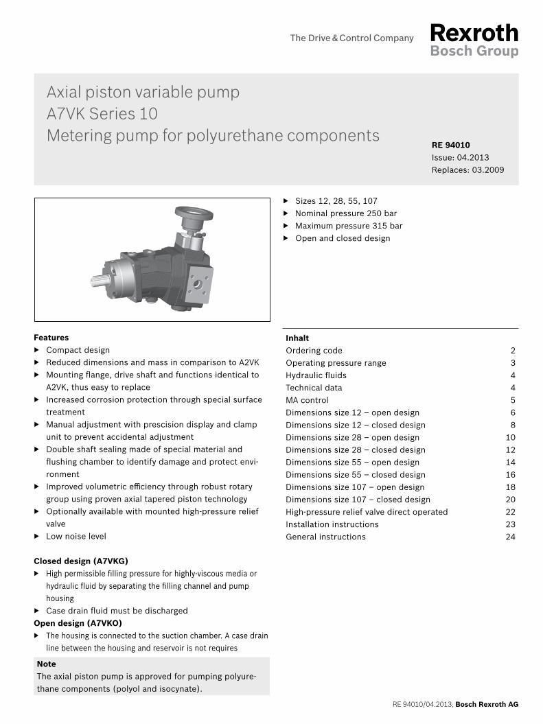
▶ Sizes 12, 28, 55, 107 ▶ Nominal pressure 250 bar ▶ Maximum pressure 315 bar ▶ Open and closed design
Axial piston variable pumpA7VK Series 10Metering pump for polyurethane components
RE 94010Issue: 04.2013Replaces: 03.2009
InhaltOrdering code 2Operating pressure range 3Hydraulic fluids 4Technical data 4MA control 5Dimensions size 12 – open design 6Dimensions size 12 – closed design 8Dimensions size 28 – open design 10Dimensions size 28 – closed design 12Dimensions size 55 – open design 14Dimensions size 55 – closed design 16Dimensions size 107 – open design 18Dimensions size 107 – closed design 20High-pressure relief valve direct operated 22Installation instructions 23General instructions 24
Bosch Rexroth AG, RE 94010/04.2013
2 A7VK Series 10 | Axial piston variable pumpOrdering code
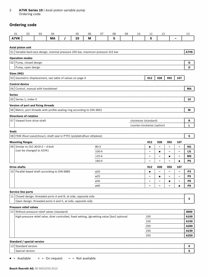
Ordering code
01 02 03 04 05 06 07 08 09 10 11 12 13
A7VK MA / 10 M S 5 –
Axial piston unit01 Variable bent-axis design, nominal pressure 250 bar, maximum pressure 315 bar A7VK
Operation modes02 Pump, closed design G
Pump, open design O
Sizes (NG)03 Geometric displacement, see table of values on page 4 012 028 055 107
Control device04 Control, manual with handwheel MA
Series05 Series 1, index 0 10
Version of port and fixing threads06 Metric, port threads with profile sealing ring according to DIN 3852 M
Directions of rotation07 Viewed from drive shaft clockwise (standard) R
counter-clockwise (option) L
Seals08 FKM (fluor-caoutchouc), shaft seal in PTFE (polytetrafluor ethylene) S
Mounting flanges 012 028 055 10709 Similar to ISO 3019-2 – 4-bolt
(can be changed to A2VK)80-4 ● – – – KG
100-4 – ● – – LG
125-4 – – ● – MS
160-4 – – – ● PS
Drive shafts 012 028 055 10710 Parallel keyed shaft according to DIN 6885 ø20 ● – – – P3
ø25 – ● – – P5
ø30 – – ● – P6
ø40 – – – ● P9
Service line ports11 Closed design: threaded ports A and B, at side, opposite side
5Open design: threaded ports A and S, at side, opposite side
Pressure relief valves12 Without pressure relief valves (standard) 0000
High-pressure relief valve, diret controlled, fixed setting, Δp-setting value [bar] optional 100 A100
150 A150
200 A200
230 A230
250 A250
Standard / special version13 Standard version 0
Special version S
● = Available ○ = On request – = Not available
RE 94010/04.2013, Bosch Rexroth AG
Axial piston variable pump | A7VK Series 10 Operating pressure range
3
Operating pressure range
Pressure at the service line ports A or B (high-pressure side)
Definition
Nominal pressure pnom 250 bar absolute The nominal pressure corresponds to the maximum design pressure.
Maximum pressure pmax 315 bar absolute The maximum pressure corresponds to the maximum operating pressure within the single operating period. The sum of the single operating periods must not ex-ceed the total operating period.
Single operating period 10 s
Total operating period 50 h
Minimum pressure 10 bar absolute Minimum pressure on the high-pressure side (A or B) that is required in order to prevent damage to the axial piston unit.
Rate of pressure change RA max 9000 bar/s Maximum permissible rate of pressure build-up and pressure reduction during a pressure change over the entire pressure range.
Closed design Pressure at the service line ports A or B (low-pressure side)
Minimum filling pressure > 1 bar absolute Depending on viscosity and flow, the filling pressure must be adjusted in such a way that a complete filling of the low pressure side of the pump is ensured.Maximum filling pressure 30 bar absolute
Open design Pressure on suction port S (inlet)
Minimum filling pressure 1 bar absolute Depending on viscosity and flow, the filling pressure must be adjusted in such a way that a complete filling of the low pressure side of the pump is ensured.Maximum filling pressure 6 bar absolute
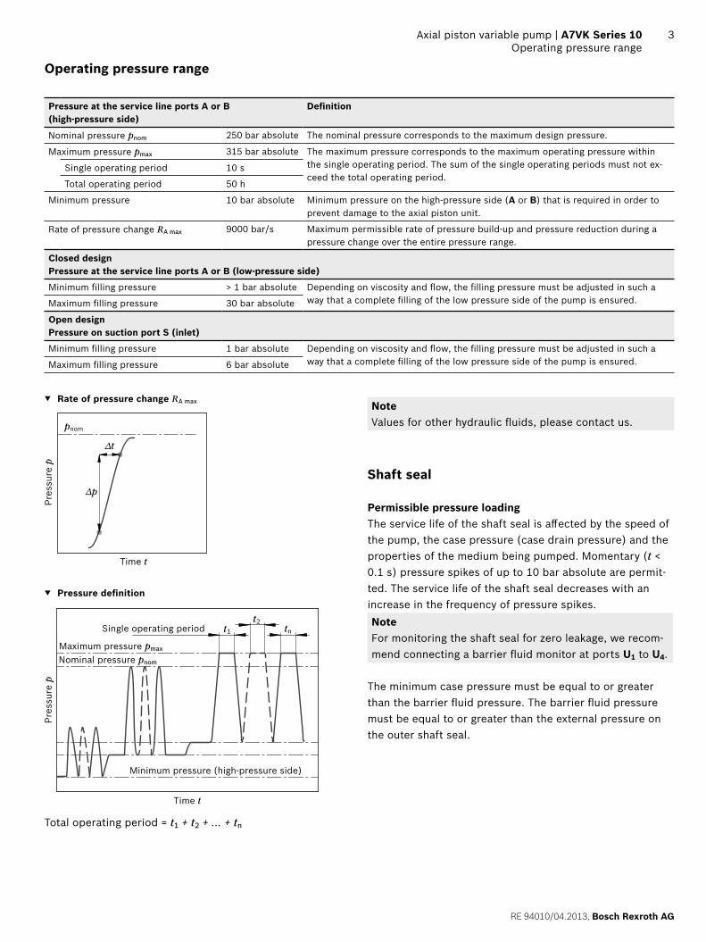
▼ Rate of pressure change RA max
pnom
∆t
∆p
Time t
Pres
sure
p
▼ Pressure definition
Pres
sure
p
t1
t2tnSingle operating period
Minimum pressure (high-pressure side)
Maximum pressure pmax
Nominal pressure pnom
Time t
Total operating period = t1 + t2 + ... + tn
NoteValues for other hydraulic fluids, please contact us.
Shaft seal
Permissible pressure loadingThe service life of the shaft seal is affected by the speed of the pump, the case pressure (case drain pressure) and the properties of the medium being pumped. Momentary (t < 0.1 s) pressure spikes of up to 10 bar absolute are permit-ted. The service life of the shaft seal decreases with an increase in the frequency of pressure spikes.NoteFor monitoring the shaft seal for zero leakage, we recom-mend connecting a barrier fluid monitor at ports U1 to U4.
The minimum case pressure must be equal to or greater than the barrier fluid pressure. The barrier fluid pressure must be equal to or greater than the external pressure on the outer shaft seal.
Bosch Rexroth AG, RE 94010/04.2013
4 A7VK Series 10 | Axial piston variable pumpHydraulic fluids
Hydraulic fluids
The pump is approved for pumping and metering polyure-thane components (polyol and isocynate). For other hydrau-lic fluids, consult with Bosch Rexroth Service.
Operating viscosity rangeThe limiting values for viscosity are as follows:
▶ νmin = 5 mm2/s ▶ νmax = 1600 mm2/s
Please contact us if different values are required.On applications with highly viscous fluids bearing flushing is recommended. Recommended flushing flow:
Size [L/min]
12 2.5
28 4
55 4
107 8
Operating temperature range ▶ Optimum operating temperature range t = 10 bis 50 °C ▶ Maximum operating temperature range tmax = 80 °C
The permissible operating temperature is dependent on the lubricity of the respective hydraulic fluid.The maximum operating temperature must not be exceeded even locally.
Filtration of the hydraulic fluidThe filter should be arranged so that only filtered fluid enters the pump. The finer the filter, the longer the service life of the axial piston pump.
▶ We recommend a filter grade ηabs ≤ 125 µm
Case drain fluid at closed designThe pump ports A and B are separated from the housing. The case drain fluid must be removed via port T1 or T2 using a separate line.
▶ Maximum case drain pressure pL max = 6 bar
Case drain fluid at open designThe housing is connected to the suction chamber. The pressure on port S is also applied in the housing and must not exceed 6 bar. A case drain line between the housing and reservoir is not required (port T1, T2 plugged).
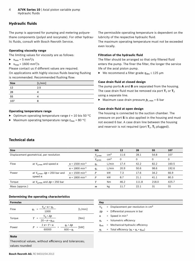
Technical data
Size NG 12 28 55 107
Displacement geometrical, per revolution Vg max cm3 11.6 28.1 54.8 107
Vg min cm3 0 0 0 0
Flow at Vg max and speed n n = 1500 min-1 qv L/min 17.4 42.2 82.2 160.5
n = 1800 min-1 qv L/min 20.9 50.6 98.6 192.6
Power at Vg max, Δp = 250 bar and speed n
n = 1500 min-1 P kW 7.3 17.6 34.2 66.9
n = 1800 min-1 P kW 8.7 21.1 41.1 80.3
Torque at Vg max and Δp = 250 bar T Nm 46.2 111.8 218.0 425.7
Mass (approx.) m kg 11.7 22.1 31 55
Determining the operating characteristics
Formulas Key
Flow qv =Vg • n • ηv
[L/min]Vg = Displacement per revolution in cm3
1000 Δp = Differential pressure in bar
Torque T = Vg • Δp
[Nm]n = Speed in min-1
20 • π • ηmh ηv = Volumetric efficiency
Power P =2 π • T • n
=qv • Δp
[kW]ηmh = Mechanical-hydraulic efficiency
60000 600 • ηt ηt = Total efficiency (ηt = ηv • ηmh)
NoteTheoretical values, without efficiency and tolerances; values rounded
RE 94010/04.2013, Bosch Rexroth AG
Axial piston variable pump | A7VK Series 10 MA control
5
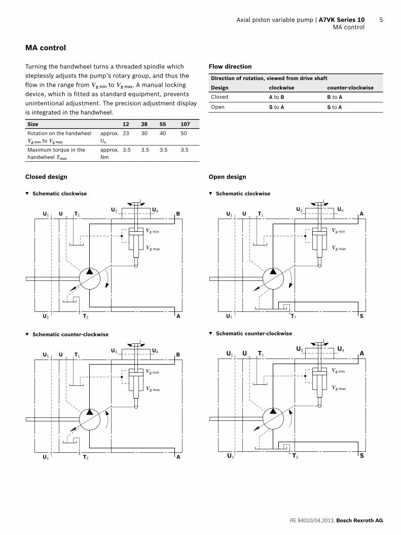
MA control
Turning the handwheel turns a threaded spindle which steplessly adjusts the pump’s rotary group, and thus the flow in the range from Vg min to Vg max. A manual locking device, which is fitted as standard equipment, prevents unintentional adjustment. The precision adjustment display is integrated in the handwheel.
Size 12 28 55 107
Rotation on the handwheel Vg min to Vg max
approx. Us
23 30 40 50
Maximum torque in the handwheel Tmax
approx.Nm
3.5 3.5 3.5 3.5
Flow direction
Direction of rotation, viewed from drive shaft
Design clockwise counter-clockwise
Closed A to B B to A
Open S to A S to A
Closed design
▼ Schematic clockwise
U1 T1 B
Vg min
Vg max
AU2 T2
U4U3U
▼ Schematic counter-clockwise
Vg min
Vg max
U4U3U1 T1 B
AU2 T2
U
Open design
▼ Schematic clockwise
U1 T1 A
SU2 T2
UU4U3
Vg min
Vg max
▼ Schematic counter-clockwise
U1 T1 A
SU2 T2
UU4U3
Vg min
Vg max
Bosch Rexroth AG, RE 94010/04.2013
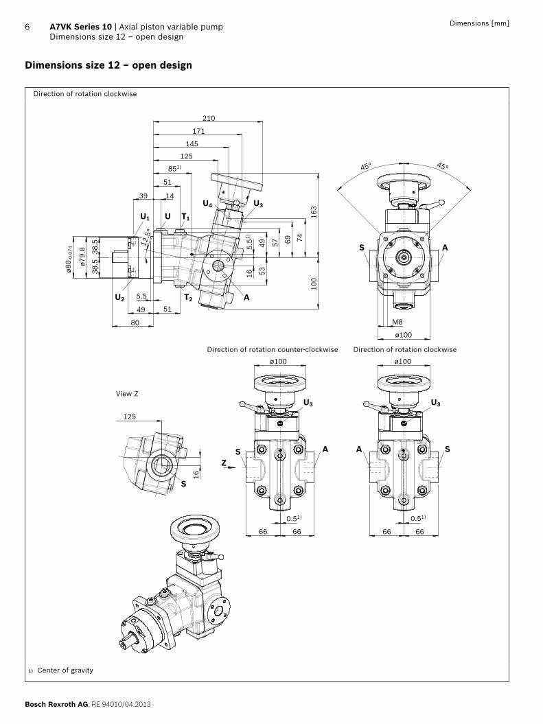
6 A7VK Series 10 | Axial piston variable pumpDimensions size 12 – open design
Dimensions [mm]
Dimensions size 12 – open design
Direction of rotation clockwise
AT2
U T1
U2
U1
S A
U4 U3
SA
S
AS
U3 U3
Z
666666
125
0.51) 0.51)
66
ø100
ø100ø100
M8
45° 45°
16
53
5.51)
57
163
10016
69 74
49
39 14
51
125
171
145
210
851)
ø79.
8
ø80 -
0.07
4
5.5
49
80
51
38.5
38.5 12
.5°
View Z
Direction of rotation counter-clockwise Direction of rotation clockwise
1) Center of gravity
RE 94010/04.2013, Bosch Rexroth AG
Axial piston variable pump | A7VK Series 10 Dimensions size 12 – open design
7Dimensions [mm]
1) Center bore according to DIN 332 (thread according to DIN 13)2) Observe the general instructions on page 24 for the maximum
tightening torques.3) Momentary pressure spikes may occur depending on the application.
Keep this in mind when selecting measuring devices and fittings.4) The spot face can be deeper than specified in the appropriate standard.
5) The minimum case pressure must be equal to or greater than the barrier fluid pressure. The barrier fluid pressure must be equal to or greater than the external pressure on the outer shaft seal.
6) O = Must be connected (plugged on delivery) X = Plugged (in normal operation)
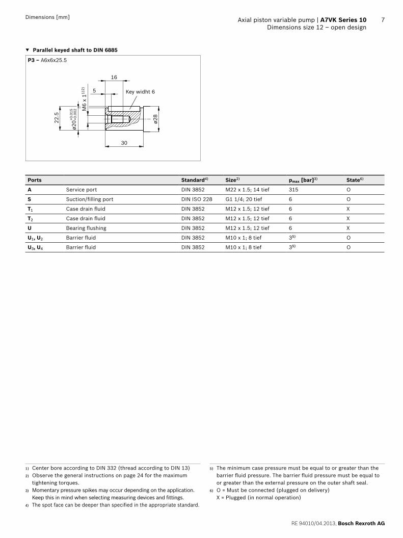
▼ Parallel keyed shaft to DIN 6885
P3 ‒ A6x6x25.5
Key widht 6
22.5
ø20
30
M6
x 11)
2) 5
16
ø28
+0.
002
+0.0
15
Ports Standard4) Size2) pmax [bar]3) State6)
A Service port DIN 3852 M22 x 1.5; 14 tief 315 O
S Suction/filling port DIN ISO 228 G1 1/4; 20 tief 6 O
T1 Case drain fluid DIN 3852 M12 x 1.5; 12 tief 6 X
T2 Case drain fluid DIN 3852 M12 x 1.5; 12 tief 6 X
U Bearing flushing DIN 3852 M12 x 1.5; 12 tief 6 X
U1, U2 Barrier fluid DIN 3852 M10 x 1; 8 tief 35) O
U3, U4 Barrier fluid DIN 3852 M10 x 1; 8 tief 35) O
Bosch Rexroth AG, RE 94010/04.2013
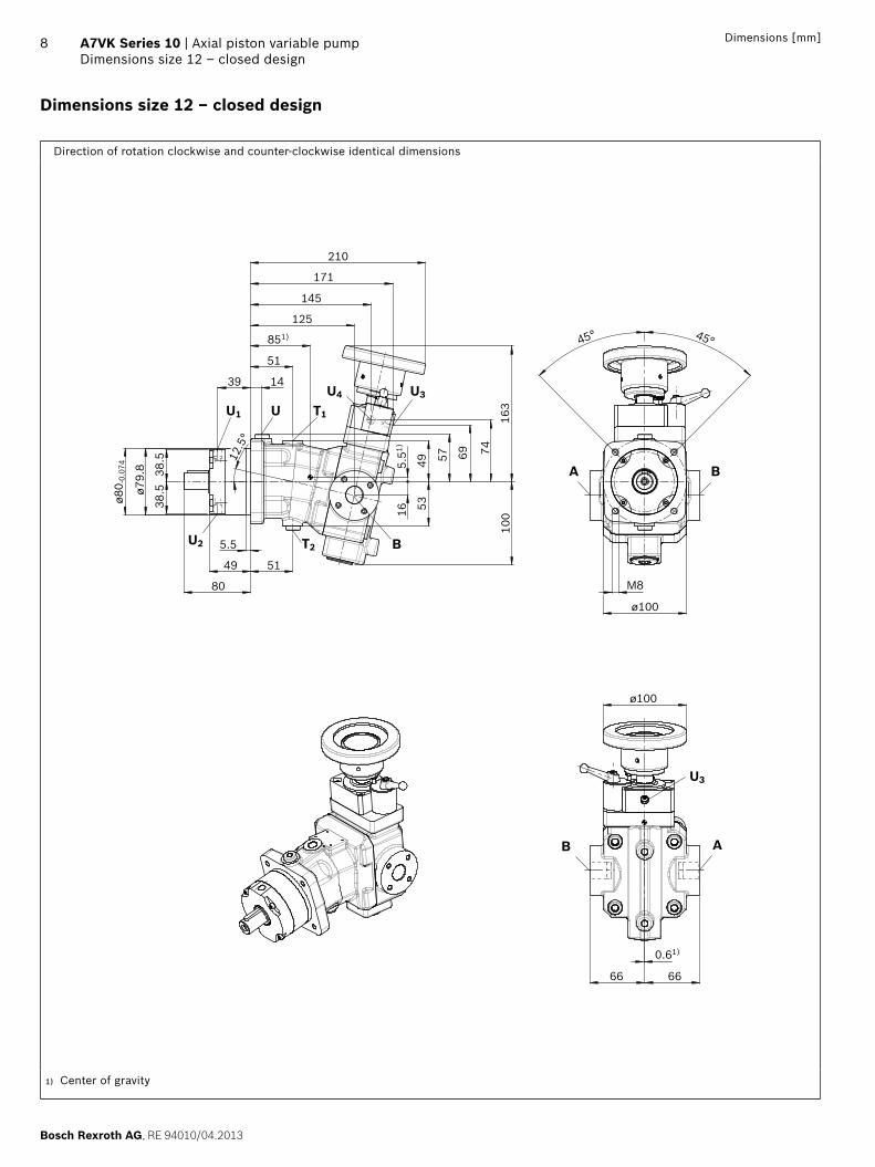
8 A7VK Series 10 | Axial piston variable pumpDimensions size 12 – closed design
Dimensions [mm]
Dimensions size 12 – closed design
Direction of rotation clockwise and counter-clockwise identical dimensions
6666
0.61)
ø100
ø100
M8
45° 45°
5349
16
100
163
7457 69
5.51)
ø79.
8
ø80 -
0.07
4 12.5
°
5.5
49 51
80
38.5
38.5
125
39
51
171
851)
14
145
210
AB
U3
A B
B
T1
T2
U
U2
U1
U4 U3
1) Center of gravity

RE 94010/04.2013, Bosch Rexroth AG
Axial piston variable pump | A7VK Series 10 Dimensions size 12 – closed design
9Dimensions [mm]
1) Center bore according to DIN 332 (thread according to DIN 13)2) Observe the general instructions on page 24 for the maximum
tightening torques.3) Momentary pressure spikes may occur depending on the application.
Keep this in mind when selecting measuring devices and fittings.4) The spot face can be deeper than specified in the appropriate standard.
5) The minimum case pressure must be equal to or greater than the barrier fluid pressure. The barrier fluid pressure must be equal to or greater than the external pressure on the outer shaft seal.
6) Depending on installation position, T1 or T2 must be connected (see also installation instructions page 23).
7) O = Must be connected (plugged on delivery) X = Plugged (in normal operation)
▼ Parallel keyed shaft DIN 6885
P3 ‒ A6x6x25.5
Key width 6
22.5
ø20
30
M6
x 11)
2) 5
16
ø28
+0.
002
+0.0
15
Ports Standard4) Size2) pmax [bar]3) State7)
A Service port DIN 3852 M22 x 1.5; 14 tief clockwise 30 O
counter-clockwise 315
B Service port DIN 3852 M22 x 1.5; 14 tief clockwise 315 O
counter-clockwise 30
T1 Case drain fluid DIN 3852 M12 x 1.5; 12 tief 6 O6)
T2 Case drain fluid DIN 3852 M12 x 1.5; 12 tief 6 X6)
U Bearing flushing DIN 3852 M12 x 1.5; 12 tief 6 X
U1, U2 Barrier fluid DIN 3852 M10 x 1; 8 tief 35) O
U3, U4 Barrier fluid DIN 3852 M10 x 1; 8 tief 35) O
Bosch Rexroth AG, RE 94010/04.2013
10 A7VK Series 10 | Axial piston variable pumpDimensions size 28 – open design
Dimensions [mm]
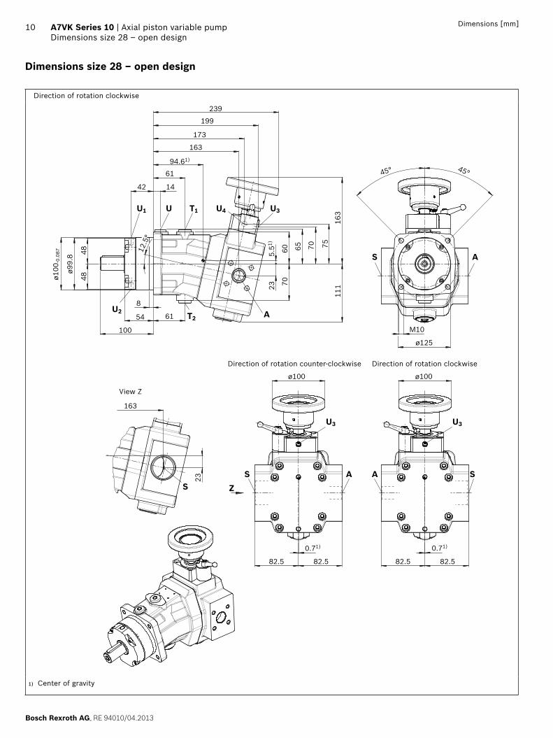
Dimensions size 28 – open design
Direction of rotation clockwise
82.582.582.582.5
0.71)0.71)
ø100ø100
ø125
M10
45° 45°
42
163
199
173
239
94.61)
61
14
7060
163
111
65 70 75
235.
51)
8
54
100
61
ø99.
8
ø100
-0.0
87
4848 12
.5°
23
163
ZSA
U3
AS
U3
S A
U T1U1 U4 U3
T2U2 A
S
View Z
Direction of rotation counter-clockwise Direction of rotation clockwise
1) Center of gravity
RE 94010/04.2013, Bosch Rexroth AG
Axial piston variable pump | A7VK Series 10 Dimensions size 28 – open design
11Dimensions [mm]
1) Center bore according to DIN 332 (thread according to DIN 13)2) Observe the general instructions on page 24 for the maximum
tightening torques.3) Momentary pressure spikes may occur depending on the application.
Keep this in mind when selecting measuring devices and fittings.4) The spot face can be deeper than specified in the appropriate standard.
5) The minimum case pressure must be equal to or greater than the barrier fluid pressure. The barrier fluid pressure must be equal to or greater than the external pressure on the outer shaft seal.
6) O = Must be connected (plugged on delivery) X = Plugged (in normal operation)
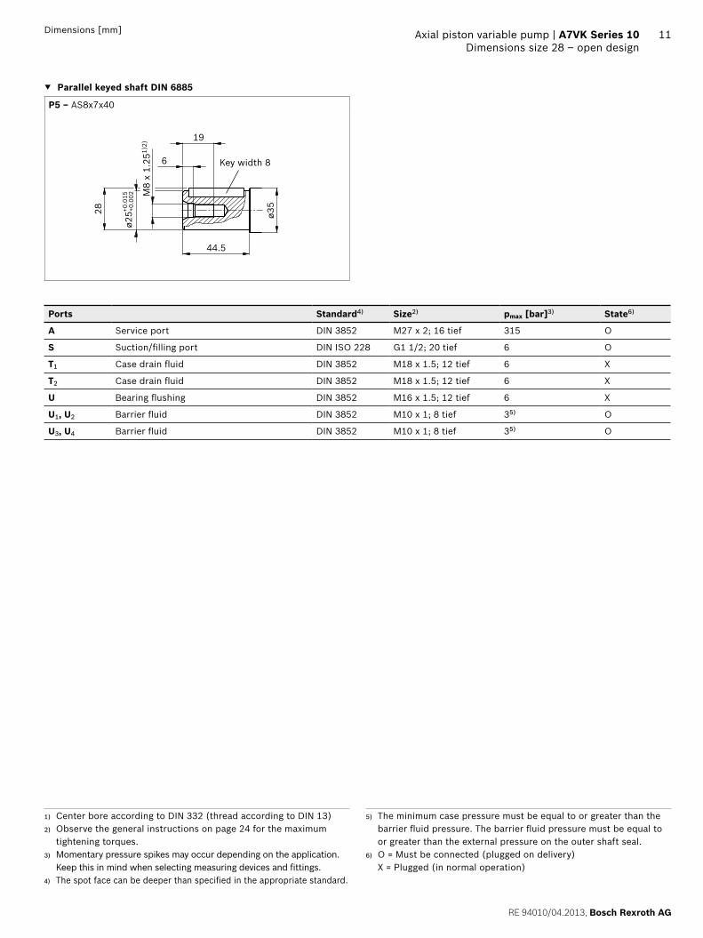
▼ Parallel keyed shaft DIN 6885
P5 ‒ AS8x7x40
Key width 8
28
ø25 +
0.00
2
44.5
M8
x 1.
251)
2)
6
19
ø35+0.0
15
Ports Standard4) Size2) pmax [bar]3) State6)
A Service port DIN 3852 M27 x 2; 16 tief 315 O
S Suction/filling port DIN ISO 228 G1 1/2; 20 tief 6 O
T1 Case drain fluid DIN 3852 M18 x 1.5; 12 tief 6 X
T2 Case drain fluid DIN 3852 M18 x 1.5; 12 tief 6 X
U Bearing flushing DIN 3852 M16 x 1.5; 12 tief 6 X
U1, U2 Barrier fluid DIN 3852 M10 x 1; 8 tief 35) O
U3, U4 Barrier fluid DIN 3852 M10 x 1; 8 tief 35) O
Bosch Rexroth AG, RE 94010/04.2013
12 A7VK Series 10 | Axial piston variable pumpDimensions size 28 – closed design
Dimensions [mm]
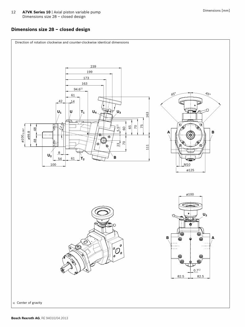
Dimensions size 28 – closed design
Direction of rotation clockwise and counter-clockwise identical dimensions
B A
U3
BA
U T1U1 U4 U3
T2U2 B
ø100
82.582.5
0.71)
ø125
45° 45°
M10
11123 70
60 65
163
70 75
5.51)
8
54
100
61
ø99.
8
ø100
-0.0
87
4848
42
163
199
173
239
94.61)
61
14
12.5
°
1) Center of gravity

RE 94010/04.2013, Bosch Rexroth AG
Axial piston variable pump | A7VK Series 10 Dimensions size 28 – closed design
13Dimensions [mm]
1) Center bore according to DIN 332 (thread according to DIN 13)2) Observe the general instructions on page 24 for the maximum
tightening torques.3) Momentary pressure spikes may occur depending on the application.
Keep this in mind when selecting measuring devices and fittings.4) The spot face can be deeper than specified in the appropriate standard.
5) The minimum case pressure must be equal to or greater than the barrier fluid pressure. The barrier fluid pressure must be equal to or greater than the external pressure on the outer shaft seal.
6) Depending on installation position, T1 or T2 must be connected (see also installation instructions page 23).
7) O = Must be connected (plugged on delivery) X = Plugged (in normal operation)
▼ Parallel keyed shaft DIN 6885
P5 ‒ AS8x7x40
Key width 8
28
ø25 +
0.00
2
44.5
M8
x 1.
251)
2)
6
19
ø35+0.0
15
Ports Standard4) Size2) pmax [bar]3) State7)
A Service port DIN 3852 M27 x 2; 16 tief clockwise 30 O
counter-clockwise 315
B Service port DIN 3852 M27 x 2; 16 tief clockwise 315 O
counter-clockwise 30
T1 Case drain fluid DIN 3852 M18 x 1.5; 12 tief 6 O6)
T2 Case drain fluid DIN 3852 M18 x 1.5; 12 tief 6 X6)
U Bearing flushing DIN 3852 M16 x 1.5; 12 tief 6 X
U1, U2 Barrier fluid DIN 3852 M10 x 1; 8 tief 35) O
U3, U4 Barrier fluid DIN 3852 M10 x 1; 8 tief 35) O
Bosch Rexroth AG, RE 94010/04.2013
14 A7VK Series 10 | Axial piston variable pumpDimensions size 55 – open design
Dimensions [mm]
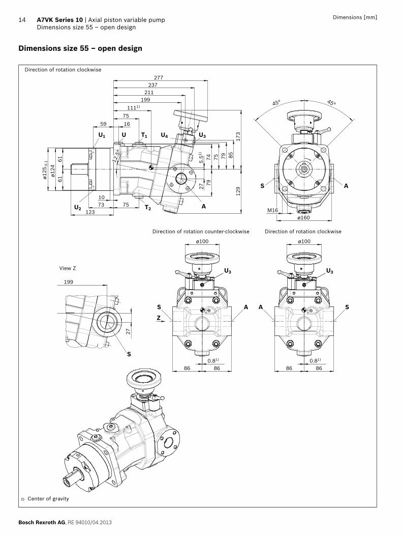
Dimensions size 55 – open design
Direction of rotation clockwise
ø100
86860.81)
ø100
86860.81)
2779
129
5.51)
74 75 79 8517
3
757310
123
6161
ø124
ø125
-0.1 12
.5°
277237
211199
1111)
751659
27
199
M16
45° 45°
ø160
A S
U3
S A
U3
Z
U T1 U4 U3
T2 AU2
U1
S
AS
Direction of rotation counter-clockwise
View Z
Direction of rotation clockwise
1) Center of gravity
RE 94010/04.2013, Bosch Rexroth AG
Axial piston variable pump | A7VK Series 10 Dimensions size 55 – open design
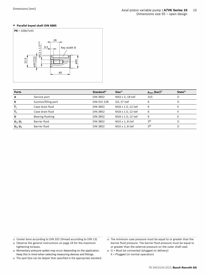
15Dimensions [mm]
1) Center bore according to DIN 332 (thread according to DIN 13)2) Observe the general instructions on page 24 for the maximum
tightening torques.3) Momentary pressure spikes may occur depending on the application.
Keep this in mind when selecting measuring devices and fittings.4) The spot face can be deeper than specified in the appropriate standard.
5) The minimum case pressure must be equal to or greater than the barrier fluid pressure. The barrier fluid pressure must be equal to or greater than the external pressure on the outer shaft seal.
6) O = Must be connected (plugged on delivery) X = Plugged (in normal operation)
▼ Parallel keyed shaft DIN 6885
P6 ‒ AS8x7x43
Key width 8
ø30+0
.015
32.9
49
M12
x 1
.51)
2)
9.5
28
ø45
+0.0
02
Ports Standard4) Size2) pmax [bar]3) State6)
A Service port DIN 3852 M33 x 2; 18 tief 315 O
S Suction/filling port DIN ISO 228 G2; 27 tief 6 O
T1 Case drain fluid DIN 3852 M18 x 1.5; 12 tief 6 X
T2 Case drain fluid DIN 3852 M18 x 1.5; 12 tief 6 X
U Bearing flushing DIN 3852 M18 x 1.5; 12 tief 6 X
U1, U2 Barrier fluid DIN 3852 M10 x 1; 8 tief 35) O
U3, U4 Barrier fluid DIN 3852 M10 x 1; 8 tief 35) O
Bosch Rexroth AG, RE 94010/04.2013
16 A7VK Series 10 | Axial piston variable pumpDimensions size 55 – closed design
Dimensions [mm]
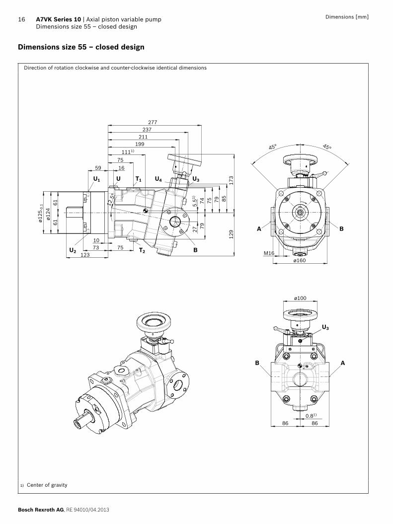
Dimensions size 55 – closed design
Direction of rotation clockwise and counter-clockwise identical dimensions
B A
U3
BA
U T1 U4 U3
T2 BU2
U1
ø100
86860.81)
2779
129
5.51)
74 75 79 8517
3
277237
211199
1111)
751659
12.5
°
M16ø160
7573123
6161
ø124
ø125
-0.1
45° 45°
10
1) Center of gravity
RE 94010/04.2013, Bosch Rexroth AG
Axial piston variable pump | A7VK Series 10 Dimensions size 55 – closed design
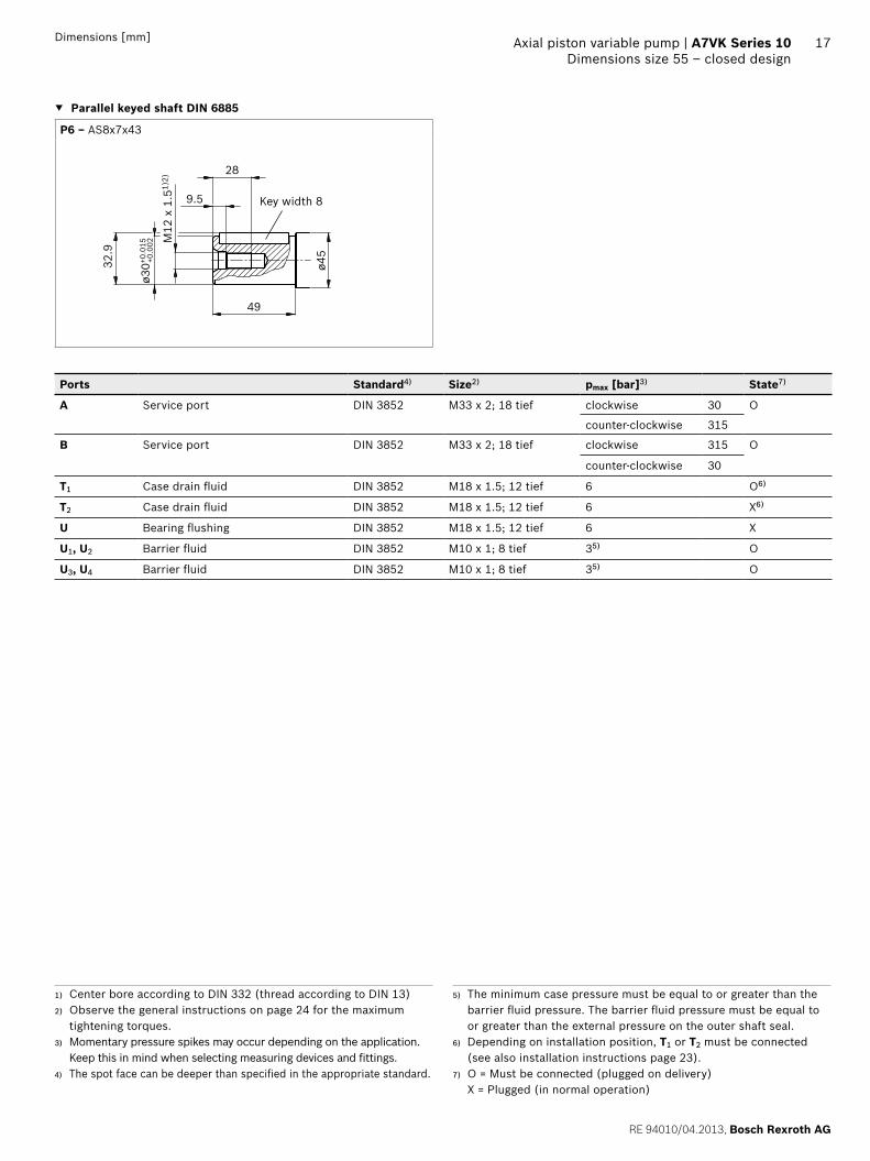
17Dimensions [mm]
1) Center bore according to DIN 332 (thread according to DIN 13)2) Observe the general instructions on page 24 for the maximum
tightening torques.3) Momentary pressure spikes may occur depending on the application.
Keep this in mind when selecting measuring devices and fittings.4) The spot face can be deeper than specified in the appropriate standard.
5) The minimum case pressure must be equal to or greater than the barrier fluid pressure. The barrier fluid pressure must be equal to or greater than the external pressure on the outer shaft seal.
6) Depending on installation position, T1 or T2 must be connected (see also installation instructions page 23).
7) O = Must be connected (plugged on delivery) X = Plugged (in normal operation)
▼ Parallel keyed shaft DIN 6885
P6 ‒ AS8x7x43
Key width 8
ø30+0
.015
32.9
49
M12
x 1
.51)
2)
9.5
28
ø45
+0.0
02
Ports Standard4) Size2) pmax [bar]3) State7)
A Service port DIN 3852 M33 x 2; 18 tief clockwise 30 O
counter-clockwise 315
B Service port DIN 3852 M33 x 2; 18 tief clockwise 315 O
counter-clockwise 30
T1 Case drain fluid DIN 3852 M18 x 1.5; 12 tief 6 O6)
T2 Case drain fluid DIN 3852 M18 x 1.5; 12 tief 6 X6)
U Bearing flushing DIN 3852 M18 x 1.5; 12 tief 6 X
U1, U2 Barrier fluid DIN 3852 M10 x 1; 8 tief 35) O
U3, U4 Barrier fluid DIN 3852 M10 x 1; 8 tief 35) O
Bosch Rexroth AG, RE 94010/04.2013
18 A7VK Series 10 | Axial piston variable pumpDimensions size 107 – open design
Dimensions [mm]
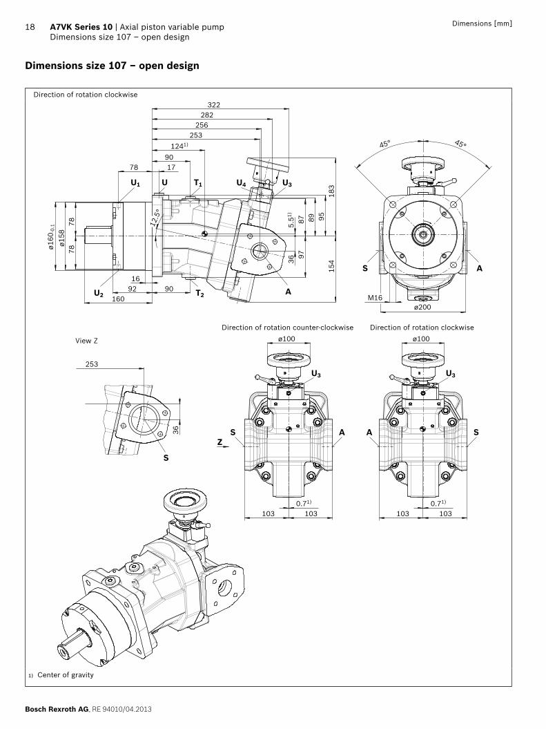
Dimensions size 107 – open design
Direction of rotation clockwise
1031030.71)
1031030.71)
ø100ø100
253
36
45° 45°
M16ø200
909216
160
7878
ø158
ø160
-0.1 12
.5°
322282
256253
1241)
901778
3697
154
5.51)
87 89 9518
3
A S
U3
AS
U3
Z
S
S A
U1 U T1 U4 U3
U2 T2 A
Direction of rotation counter-clockwise Direction of rotation clockwise
View Z
1) Center of gravity

RE 94010/04.2013, Bosch Rexroth AG
Axial piston variable pump | A7VK Series 10 Dimensions size 107 – open design
19Dimensions [mm]
1) Center bore according to DIN 332 (thread according to DIN 13)2) Observe the general instructions on page 24 for the maximum
tightening torques.3) Momentary pressure spikes may occur depending on the application.
Keep this in mind when selecting measuring devices and fittings.4) The spot face can be deeper than specified in the appropriate standard.
5) The minimum case pressure must be equal to or greater than the barrier fluid pressure. The barrier fluid pressure must be equal to or greater than the external pressure on the outer shaft seal.
6) O = Must be connected (plugged on delivery) X = Plugged (in normal operation)
▼ Parallel keyed shaft DIN 6885
P9 ‒ AS12x8x63
Key width 12
ø40+0
.018
43
68
M12
x 1
.51)
2)
9.5
28
ø50
+0.0
02
Ports Standard4) Size2) pmax [bar]3) State6)
A Service port DIN 3852 M42 x 2; 20 tief 315 O
S Suction/filling port DIN ISO 228 G2 1/2; 30 tief 6 O
T1 Case drain fluid DIN 3852 M18 x 1.5; 12 tief 6 X
T2 Case drain fluid DIN 3852 M18 x 1.5; 12 tief 6 X
U Bearing flushing DIN 3852 M18 x 1.5; 12 tief 6 X
U1, U2 Barrier fluid DIN 3852 M10 x 1; 8 tief 35) O
U3, U4 Barrier fluid DIN 3852 M10 x 1; 8 tief 35) O
Bosch Rexroth AG, RE 94010/04.2013
20 A7VK Series 10 | Axial piston variable pumpDimensions size 107 – closed design
Dimensions [mm]
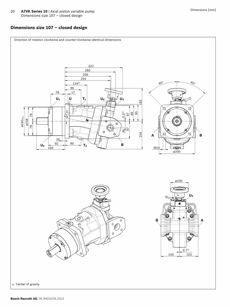
Dimensions size 107 – closed design
Direction of rotation clockwise and counter-clockwise identical dimensions
ø100
1031030.71)
M16
45° 45°
ø200
3697
154
5.51)
87 89 9518
3
322282
256253
1241)
901778
909216
160
7878
ø158
ø160
-0.1 12
.5°
B A
U3
A B
U1 U T1 U4 U3
U2 T2 B
1) Center of gravity
RE 94010/04.2013, Bosch Rexroth AG
Axial piston variable pump | A7VK Series 10 Dimensions size 107 – closed design
21Dimensions [mm]
1) Center bore according to DIN 332 (thread according to DIN 13)2) Observe the general instructions on page 24 for the maximum
tightening torques.3) Momentary pressure spikes may occur depending on the application.
Keep this in mind when selecting measuring devices and fittings.4) The spot face can be deeper than specified in the appropriate standard.
5) The minimum case pressure must be equal to or greater than the barrier fluid pressure. The barrier fluid pressure must be equal to or greater than the external pressure on the outer shaft seal.
6) Depending on installation position, T1 or T2 must be connected (see also installation instructions page 23).
7) O = Must be connected (plugged on delivery) X = Plugged (in normal operation)
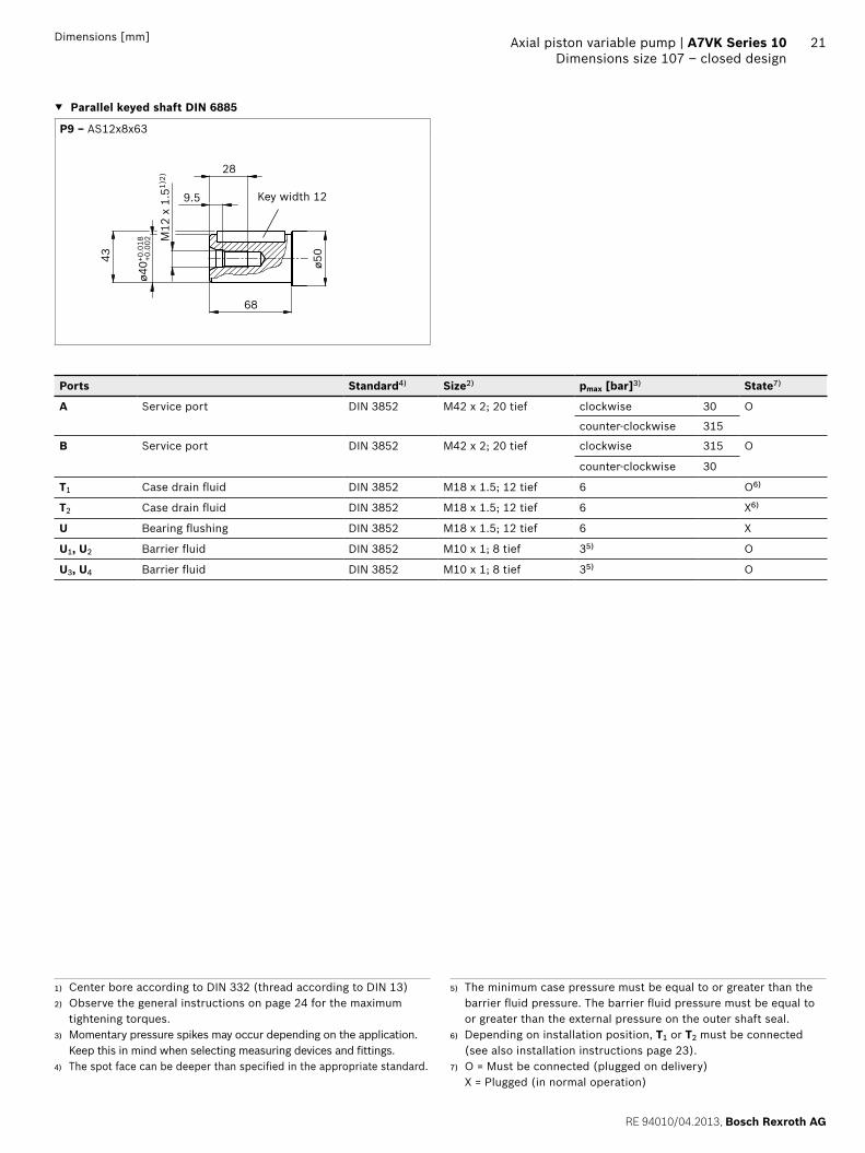
▼ Parallel keyed shaft DIN 6885
P9 ‒ AS12x8x63
Key width 12
ø40+0
.018
43
68
M12
x 1
.51)
2)
9.5
28
ø50
+0.0
02
Ports Standard4) Size2) pmax [bar]3) State7)
A Service port DIN 3852 M42 x 2; 20 tief clockwise 30 O
counter-clockwise 315
B Service port DIN 3852 M42 x 2; 20 tief clockwise 315 O
counter-clockwise 30
T1 Case drain fluid DIN 3852 M18 x 1.5; 12 tief 6 O6)
T2 Case drain fluid DIN 3852 M18 x 1.5; 12 tief 6 X6)
U Bearing flushing DIN 3852 M18 x 1.5; 12 tief 6 X
U1, U2 Barrier fluid DIN 3852 M10 x 1; 8 tief 35) O
U3, U4 Barrier fluid DIN 3852 M10 x 1; 8 tief 35) O
Bosch Rexroth AG, RE 94010/04.2013
22 A7VK Series 10 | Axial piston variable pumpHigh-pressure relief valve direct operated
Dimensions [mm]
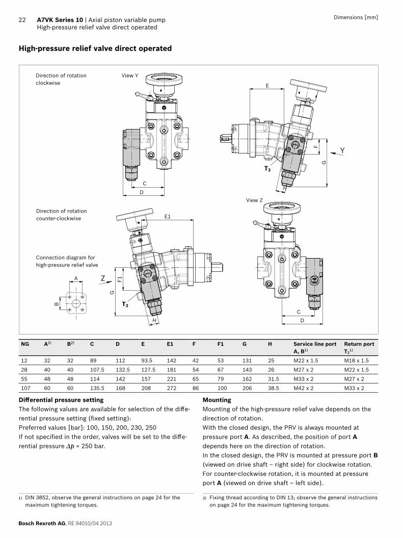
High-pressure relief valve direct operated
A
B
E
Y
GF
HC
D
T3
H
T3C
D
E1
Z
GF1
View Y
Connection diagram for high-pressure relief valve
View Z
Direction of rotation clockwise
Direction of rotation counter-clockwise
NG A2) B2) C D E E1 F F1 G H Service line port A, B1)
Return port T3
1)
12 32 32 89 112 93.5 142 42 53 131 25 M22 x 1.5 M18 x 1.5
28 40 40 107.5 132.5 127.5 181 54 67 143 26 M27 x 2 M22 x 1.5
55 48 48 114 142 157 221 65 79 162 31.5 M33 x 2 M27 x 2
107 60 60 135.5 168 208 272 86 100 206 38.5 M42 x 2 M33 x 2
Differential pressure settingThe following values are available for selection of the diffe-rential pressure setting (fixed setting): Preferred values [bar]: 100, 150, 200, 230, 250 If not specified in the order, valves will be set to the diffe-rential pressure Δp = 250 bar.
MountingMounting of the high-pressure relief valve depends on the direction of rotation.With the closed design, the PRV is always mounted at pressure port A. As described, the position of port A depends here on the direction of rotation.In the closed design, the PRV is mounted at pressure port B (viewed on drive shaft – right side) for clockwise rotation. For counter-clockwise rotation, it is mounted at pressure port A (viewed on drive shaft – left side).
1) DIN 3852, observe the general instructions on page 24 for the maximum tightening torques.
2) Fixing thread according to DIN 13; observe the general instructions on page 24 for the maximum tightening torques.
RE 94010/04.2013, Bosch Rexroth AG
Axial piston variable pump | A7VK Series 10 Installation instructions
23
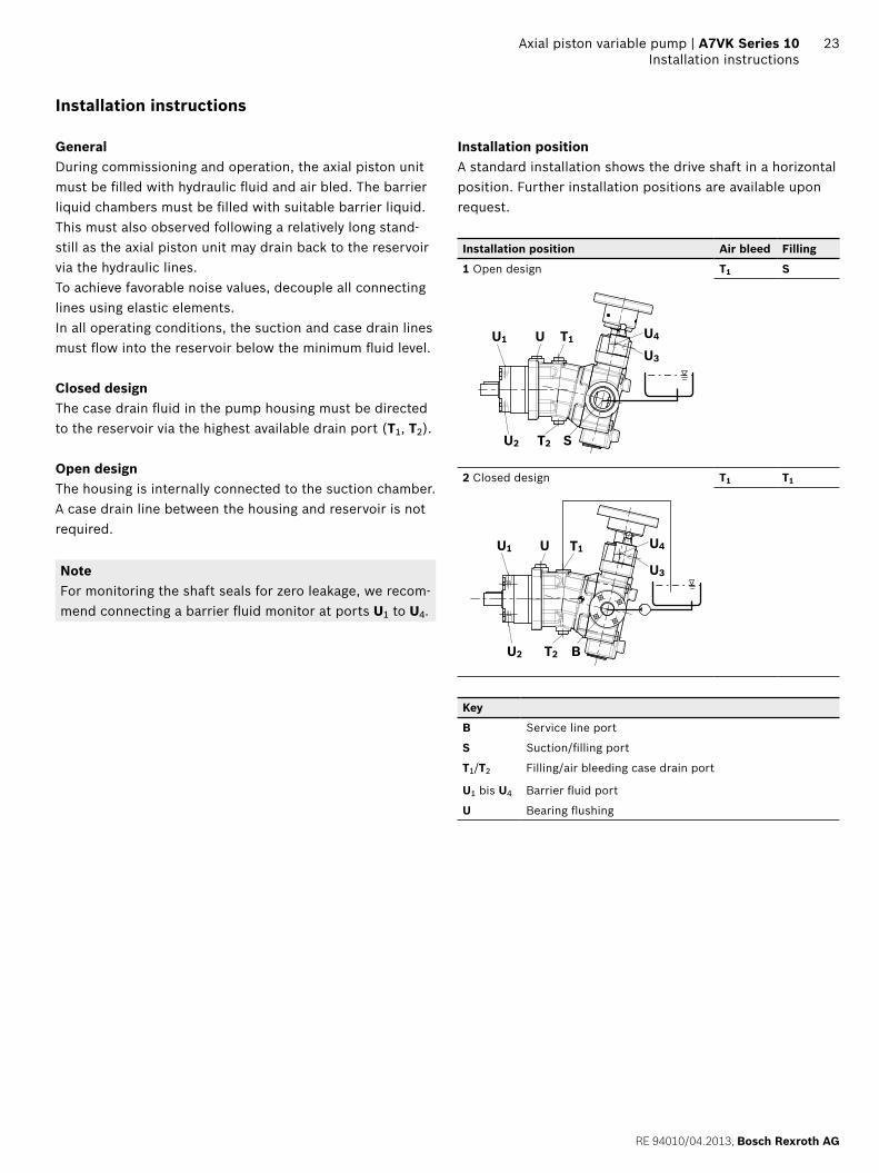
Installation instructions
GeneralDuring commissioning and operation, the axial piston unit must be filled with hydraulic fluid and air bled. The barrier liquid chambers must be filled with suitable barrier liquid. This must also observed following a relatively long stand-still as the axial piston unit may drain back to the reservoir via the hydraulic lines.To achieve favorable noise values, decouple all connecting lines using elastic elements. In all operating conditions, the suction and case drain lines must flow into the reservoir below the minimum fluid level.
Closed designThe case drain fluid in the pump housing must be directed to the reservoir via the highest available drain port (T1, T2).
Open designThe housing is internally connected to the suction chamber. A case drain line between the housing and reservoir is not required.
NoteFor monitoring the shaft seals for zero leakage, we recom-mend connecting a barrier fluid monitor at ports U1 to U4.
Installation positionA standard installation shows the drive shaft in a horizontal position. Further installation positions are available upon request.
Installation position Air bleed Filling
1 Open design T1 S
U1 U T1
U2 T2
U4
U3
S
2 Closed design T1 T1
U1 U T1
U2 T2 B
U3
U4
Key
B Service line port
S Suction/filling port
T1/T2 Filling/air bleeding case drain port
U1 bis U4 Barrier fluid port
U Bearing flushing
24
Bosch Rexroth AG, RE 94010/04.2013
Bosch Rexroth AGMobile ApplicationsGlockeraustraße 489275 Elchingen, GermanyTel. +49 7308 [email protected]
© Alle Rechte bei Bosch Rexroth AG, auch für den Fall von Schutzrechts-anmeldungen. Jede Verfügungsbefugnis, wie Kopier- und Weitergaberecht, bei uns. Die angegebenen Daten dienen allein der Produktbeschreibung. Eine Aussage über eine bestimmte Beschaffenheit oder eine Eignung für einen bestimmten Einsatzzweck kann aus unseren Angaben nicht abgeleitet werden. Die Angaben entbinden den Verwender nicht von eigenen Beurtei-lungen und Prüfungen. Es ist zu beachten, dass unsere Produkte einem natürlichen Verschleiß- und Alterungsprozess unterliegen.
A7VK Series 10 | Axial piston variable pumpGeneral instructions
General instructions
▶ The pump A7VK is designed for pumping polyurethane components in open and closed design.
▶ The project planning, installation and commissioning of the axial piston unit requires the involvement of quali-fied personnel.
▶ Before using the axial piston unit, please read the corre-sponding instruction manual completely and thoroughly. If necessary, these can be requested from Bosch Rexroth.
▶ During and shortly after operation, there is a risk of burns on the axial piston unit and pressure relief valve on the service line port. Take appropriate safety measures (e.g. by wearing protective clothing).
▶ Service line ports – The ports and fastening threads are designed for the
specified maximum pressure. The machine or system manufacturer must ensure that the connecting ele-ments and lines correspond to the specified operating conditions (pressure, flow, hydraulic fluid, tempera-ture) with the necessary safety factors.
– The service line ports and function ports are only designed to accommodate hydraulic lines.
▶ The data and notes contained herein must be adhered to.
▶ Before finalizing your design, request a binding installa-tion drawing.
▶ Not all versions of the product are approved for use in a safety function pursuant to ISO 13849. If you require characteristic values relating to reliability (e.g. MTTFd) for functional safety, please consult the responsible contact person at Bosch Rexroth.
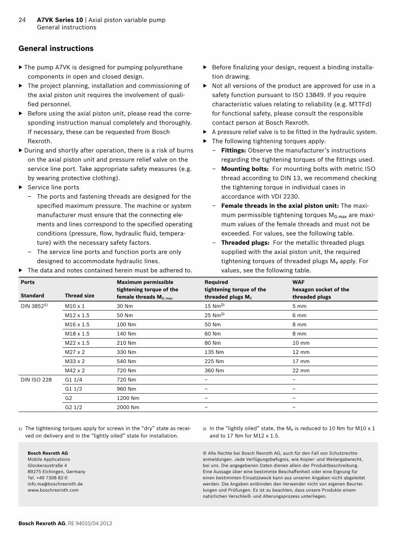
▶ A pressure relief valve is to be fitted in the hydraulic system. ▶ The following tightening torques apply:
– Fittings: Observe the manufacturer’s instructions regarding the tightening torques of the fittings used.
– Mounting bolts: For mounting bolts with metric ISO thread according to DIN 13, we recommend checking the tightening torque in individual cases in accordance with VDI 2230.
– Female threads in the axial piston unit: The maxi-mum permissible tightening torques MG max are maxi-mum values of the female threads and must not be exceeded. For values, see the following table.
– Threaded plugs: For the metallic threaded plugs supplied with the axial piston unit, the required tightening torques of threaded plugs MV apply. For values, see the following table.
Ports Maximum permissible tightening torque of the female threads MG max
Required tightening torque of the threaded plugs MV
WAF hexagon socket of the threaded plugsStandard Thread size
DIN 38521) M10 x 1 30 Nm 15 Nm2) 5 mm
M12 x 1.5 50 Nm 25 Nm2) 6 mm
M16 x 1.5 100 Nm 50 Nm 8 mm
M18 x 1.5 140 Nm 60 Nm 8 mm
M22 x 1.5 210 Nm 80 Nm 10 mm
M27 x 2 330 Nm 135 Nm 12 mm
M33 x 2 540 Nm 225 Nm 17 mm
M42 x 2 720 Nm 360 Nm 22 mm
DIN ISO 228 G1 1/4 720 Nm − −
G1 1/2 960 Nm – –
G2 1200 Nm – –
G2 1/2 2000 Nm – –
1) The tightening torques apply for screws in the “dry” state as recei-ved on delivery and in the “lightly oiled” state for installation.
2) In the “lightly oiled” state, the MV is reduced to 10 Nm for M10 x 1 and to 17 Nm for M12 x 1.5.