axial piston variable pump a4vg series 40 · technical data 9 hp – proportional control, hydr.,...
TRANSCRIPT

Americas | RE-A 92004/09.2017, Bosch Rexroth AG
Features ▶ High power density owing to a very high pressure level ▶ Integrated auxiliary pump for boost and pilot oil supply ▶ Flow direction changes smoothly when the swashplate
is moved through the neutral position ▶ High-pressure relief valves with integrated boost
function ▶ With adjustable pressure cut-off as standard ▶ Boost-pressure relief valve ▶ Through drive for mounting of further pumps up to same
nominal size ▶ High total efficiency ▶ Large variety of controls ▶ Swashplate design
▶ High-pressure pump for applications in a closed circuit up to 7250 psi (500 bar)
▶ Size 110 … 280 ▶ Nominal pressure 6500 psi (450 bar) ▶ Maximum pressure 7250 psi (500 bar) ▶ Closed circuit
Axial piston variable pumpA4VG Series 40
RE-A 92004Edition: 09.2017Replaces: 06.2012
ContentsType code 2Hydraulic fluid 6Working pressure range 7Technical data 9HP – Proportional control, hydr., pilot-pressure related 12HW – Proportional control, hydr., mechanical servo 13HT – Hydraulic control, direct operated 15DA – Automatic control, speed related 16EP – Proportional control, electric 18EZ – Two-point control, electric 19ET – Electric control, direct operated 20Dimensions, size 110 to 280 21Dimensions, through drive 41Overview of mounting options 45Combination pumps A4VG + A4VG 46High-pressure relief valves 47Pressure cut-off 48Bypass function 48Neutral valve 49Mechanical stroke limiter 50Stroking chamber pressure port X3 and X4 51Filtration in the boost pump suction line 52Filtration in the boost pump pressure line 52External boost pressure supply 54Dimensions with mounted filter 55Swivel angle sensor 56Connector for solenoids 57Speed sensor 58Installation dimensions for coupling assembly 59Installation instructions 60Project planning notes 63Safety instructions 64
Americas

Bosch Rexroth AG, RE-A 92004/09.2017 | Americas
2 A4VG Series 40 | Axial piston variable pumpType code
Type code
01 02 03 04 05 06 07 08 09 10 11 12 13 14 15 16 17 18 19 20 21 22 23
A4V G / 40 M N A 0 −
Axial piston unit01 Swashplate design, variable, nominal pressure 6500 psi (450 bar), maximum pressure 7250 psi (500 bar) A4V
Operating mode02 Pump, closed circuit G
Size (NG)03 Geometric displacement, see “Technical data” on page 9 in3/rev. 6.71 7.63 8.85 10.68 12.81 17.09
cm3/rev. 110 125 145 175 210 280
Control device 110 125 145 175 210 28004 Proportional control,
hydraulicpilot-pressure related p = 87 to 260 psi (6 to 18 bar) − − ○ ○ ○ ○ HP1
mechanical servo, hexagon shaft with lever
− − ● ● ● ● HW2
with neutral position switch ● ● ● ● ● ● HW8
Hydraulic control, direct operated − − ● ● ○ ○ HT1
Automatic control, speed related U = 12 V ● ● − − − − DA1
U = 24 V ● ● − − − − DA2
Proportional control, electric
U = 12 V ● ● ● ● ● ● EP1
U = 24 V ● ● ● ● ● ● EP2
with manual override and spring return U = 12 V ● ● ● ● ● ● EP3
U = 24 V ● ● ● ● ● ● EP4
Two-point control, electric U = 12 V ● ● ● ● ● ● EZ1
U = 24 V ● ● ● ● ● ● EZ2
Electric control, direct operated, two pressure reducing valves (DRE) U = 12 V ● ● ● ● ○ ○ ET5
U = 24 V ● ● ● ● ○ ○ ET6
Pressure cut-off 110 … 28005 Without pressure cut-off without bypass ○ 0
with bypass ○ C
Pressure cut-off, with bypass (not for HT) Fixed setting, hydraulic, mechanical ● D
Connector for solenoids1) 110 … 28006 Without connector (only for purely hydraulic control) ● 0
DEUTSCH molded connector, 2-pin – without suppressor diode ● P
Swivel angle sensor 110 … 28007 Without swivel angle sensor ● 0
Electric swivel angle sensor (DWS20-1, 3-pin)2) ○ R
● = Available ○ = On request – = Not available = Preferred program
1) Connectors for other electric components may deviate.2) Please contact us if the swivel angle sensor is used for control

Americas | RE-A 92004/09.2017, Bosch Rexroth AG
Axial piston variable pump | A4VG Series 40 Type code
3
01 02 03 04 05 06 07 08 09 10 11 12 13 14 15 16 17 18 19 20 21 22 23
A4V G / 40 M N A 0 −
Additional function 110 … 28008 Without additional function ● 0
Mechanical stroke limiter, externally adjustable ● M
Stroking chamber pressure port X3, X4 ● T
Mechanical stroke limiter and stroking chamber pressure port X3, X4 ● B
Neutral valve U = 12 V3) ● N
and mechanical stroke limiter, externally adjustable ● P
and ports X3, X4 for stroking chamber pressure ● R
and mechanical stroke limiter and ports X3, X4 ● S
Neutral valve U = 24 V3) ● U
and mechanical stroke limiter, externally adjustable ● V
and ports X3, X4 for stroking chamber pressure ● W
and mechanical stroke limiter and ports X3, X4 ● Y
DA control valve (only for NG110 and 125) HP HW HT DA EP EZ ET09 Without DA control valve ● ● ● ‒ ● ● ● 0
DA control valve, fixed setting ● ● ● ● ● ‒ ‒ 1
DA control valve, fixed setting and brake inch valve mounted, control with brake fluid4)
based on mineral oil‒ ‒ ‒ ● ‒ ‒ ‒ 5
DA control valve, fixed setting, ports for pilot control device ● ● ● ● ● ‒ ‒ 6
Series 110 … 28010 Series 4, index 0 ● 40
Configuration of port and fastening threads 110 … 28011 ANSI with O-ring sealing according to ISO 11926 ● A
Direction of rotation 110 … 28012 Viewed on drive shaft clockwise ● R
counter-clockwise ● L
Sealing material 110 … 28013 NBR (nitrile rubber), shaft seal in FKM (fluoroelastomer) ● N
Mounting flange 110 125 145 175 210 28014 SAE J744 127-2/4 ● ● – – – – C6
152-2/4 ● ● ● ● – – D6
165-4 – – – ● ● ● E4
Drive shaft 110 125 145 175 210 28015 Splined shaft
ANSI B92.1a–19761 3/8 in 21T 16/32DP ● – – – – – V8
1 3/4 in 13T 8/16DP ● ● ● ● – – T1
2 in 15T 8/16DP ● ● ● – ● ● T2
2 1/4 in 17T 8/16DP – – ● ● ● ● T3
● = Available ○ = On request – = Not available = Preferred program
3) Cannot be combined with brake inch valve4) Cannot bei combined with neutral valve

Bosch Rexroth AG, RE-A 92004/09.2017 | Americas
4 A4VG Series 40 | Axial piston variable pumpType code
01 02 03 04 05 06 07 08 09 10 11 12 13 14 15 16 17 18 19 20 21 22 23
A4V G / 40 M N A 0 −
Working port 110 … 28016 SAE working port A and B, on left side (45° left) ● 1
SAE working port A and B, on right side (45° right)5) ● 2
Boost pump and rotary group configuration 110 125 145 175 210 28017 Standard rotary group boost pump integrated, standard internal gear pump ● ● ● ● ● ● F
boost pump integrated, large internal gear pump ● – ● ● ● – B
without boost pump ● ● ● ● ● ● U
High-speed rotary group boost pump integrated, standard internal gear pump ● – ● ● – – V
without boost pump ● – ● ● – – W
Through drive6) 110 125 145 175 210 28018 Without through drive ● ● ● ● ● ● 0000
Flange SAE J744 Hub for splined shaft7)
Diameter Mounting8) Code Diameter Code
82-2 (A) A1 5/8 in 9T 16/32DP S2 ○ – ● ● – – A1S2
A2 5/8 in 9T 16/32DP S2 ● ○ ○ ○ ○ ○ A2S2
101-2 (B) B1 7/8 in 13T 16/32DP S4 ○ ○ ● ● – – B1S4
B1 1 in 15T 16/32DP S5 ● – ○ ○ – – B1S5
B2 7/8 in 13T 16/32DP S4 ● ● ● ● ○ ● B2S4
B2 1 in 15T 16/32DP S5 ● ● ○ ● ○ ○ B2S5
B5 7/8 in 13T 16/32DP S4 – – ○ – – – B5S4
127-2 (C) C1 1 1/4 in 14T 12/24DP S7 ● – ○ ○ ○ ○ C1S7
C2 1 1/4 in 14T 12/24DP S7 ● ○ ● ● ● ○ C2S7
C2 1 3/8 in 21T 16/32DP V8 ● – ○ ○ – – C2V8
C2 1 3/4 in 13T 8/16DP T1 – – ● ○ – – C2T1
127-4 (C) C4 1 1/4 in 14T 12/24DP S7 ● – ○ ● – – C4S7
C4 1 3/8 in 21T 16/32DP V8 ○ – – – – – C4V8
152-4 (D) D4 1 3/4 in 13T 8/16DP T1 – – ● ● ● ○ D4T1
165-4 (E) E4 1 3/4 in 13T 8/16DP T1 – – – ● ○ ○ E4T1
E4 2 in 15T 8/16DP T2 – – – – ● ○ E4T2
High-pressure relief valve 110 … 28019 High-pressure relief valve, direct operated, fixed setting, with low-pressure relief valve, fixed setting ● A
Filtration boost circuit/external boost pressure supply 110 … 28020 Filtration in the boost pump suction line ● S
Filtration in the boost pump pressure line● D
Ports for external boost circuit filtration (Fe and Fa)
Attachment filter with cold start valve9) ● F
Attachment filter9) with cold start valve and electric contamination indicator – DEUTSCH connector ● B
External boost pressure supply (on version without integrated boost pump) ● E
● = Available ○ = On request – = Not available = Preferred program
5) Only possible without attachment filter.6) Specifications for version with integrated standard gear pump,
please contact us for version with integrated large gear pump or without boost pump.
7) Hub for splined shaft according to ANSI B92.1a-1976 (drive shaft allocation according to SAE J744)
8) Mounting hole pattern viewed on through drive9) Only available for working ports located on left

Americas | RE-A 92004/09.2017, Bosch Rexroth AG
Axial piston variable pump | A4VG Series 40 Type code
5
Pressure sensor 110 … 28021 Without pressure sensor ● 0
Other sensors 110 125 145 175 210 28022 Without sensor ● ● ● ● ● ● 0
Speed sensor DSM, DSA10) ○ – ○ ○ ○ ○ V
Standard / special version 110 … 28023 Standard version ● 0
Standard version with installation variants, e.g. T ports against standard open or closed ● Y
Special version ● S
01 02 03 04 05 06 07 08 09 10 11 12 13 14 15 16 17 18 19 20 21 22 23
A4V G / 40 M N A 0 −
● = Available ○ = On request – = Not available = Preferred program
Notice ▶ Note the project planning notes on page 63! ▶ In addition to the type code, please specify the rel-
evant technical data when placing your order.
10) Specify type code of sensor acc. to data sheet (DSM - 95132, DSA 95133) separately and observe the requirements on the elec-tronics
Bosch Rexroth AG, RE-A 92004/09.2017 | Americas
6 A4VG Series 40 | Axial piston variable pumpHydraulic fluid
Hydraulic fluid
The axial piston unit is designed for operation with HLP mineral oil according to DIN 51524. Application instructions and requirements for hydraulic fluid selection, behavior during operation as well as dis-posal and environmental protection should be taken from the following data sheets before the start of project plan-ning:
▶ 90220: Hydraulic fluids based on mineral oils and related hydrocarbons
▶ 90221: Environmentally acceptable hydraulic fluids ▶ 90222: Fire-resistant, water-free hydraulic fluids
(HFDR/HFDU) ▶ 90225: Limited technical data for operation with water-
free and water-containing fire-resistant hydraulic fluids (HFDR, HFDU, HFAE, HFAS, HFB, HFC)
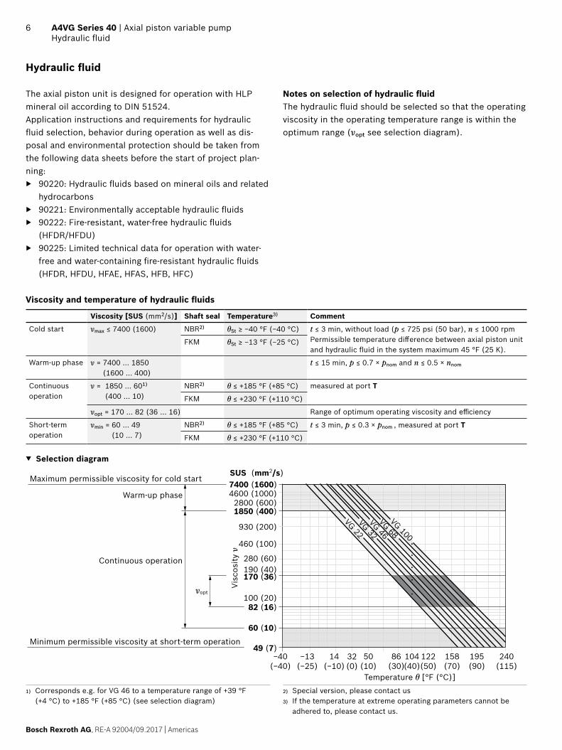
Notes on selection of hydraulic fluidThe hydraulic fluid should be selected so that the operating viscosity in the operating temperature range is within the optimum range (νopt see selection diagram).
Viscosity and temperature of hydraulic fluids
Viscosity [SUS (mm2/s)] Shaft seal Temperature3) Comment
Cold start νmax ≤ 7400 (1600) NBR2) θSt ≥ −40 °F (−40 °C) t ≤ 3 min, without load (p ≤ 725 psi (50 bar), n ≤ 1000 rpmPermissible temperature difference between axial piston unitand hydraulic fluid in the system maximum 45 °F (25 K).
FKM θSt ≥ −13 °F (−25 °C)
Warm-up phase ν = 7400 … 1850 (1600 … 400)
t ≤ 15 min, p ≤ 0.7 × pnom and n ≤ 0.5 × nnom
Continuous operation
ν = 1850 … 601) (400 … 10)
NBR2) θ ≤ +185 °F (+85 °C) measured at port T
FKM θ ≤ +230 °F (+110 °C)
νopt = 170 … 82 (36 … 16) Range of optimum operating viscosity and efficiency
Short-term operation
νmin = 60 … 49 (10 … 7)
NBR2) θ ≤ +185 °F (+85 °C) t ≤ 3 min, p ≤ 0.3 × pnom , measured at port T
FKM θ ≤ +230 °F (+110 °C)
▼ Selection diagram
−40(−40)
−13(−25)
14(−10)
50(10)
86(30)
104(40)
122(50)
195(90)
240(115)
158(70)
32(0)
49 (7)
60 (10)
190 (40)280 (60)
100 (20)
460 (100)
930 (200)
1850 (400)2800 (600)
4600 (1000)7400 (1600)
VG 22VG 32VG 46VG 68VG 100
82 (16)
170 (36)
Maximum permissible viscosity for cold start
Visc
osity
ν
Warm-up phase
Continuous operation
νopt
Minimum permissible viscosity at short-term operation
Temperature θ [°F (°C)]
SUS (mm2/s)
1) Corresponds e.g. for VG 46 to a temperature range of +39 °F (+4 °C) to +185 °F (+85 °C) (see selection diagram)
2) Special version, please contact us3) If the temperature at extreme operating parameters cannot be
adhered to, please contact us.
Americas | RE-A 92004/09.2017, Bosch Rexroth AG
Axial piston variable pump | A4VG Series 40 Working pressure range
7
Filtration of the hydraulic fluidFiner filtration improves the cleanliness level of the hydrau-lic fluid, which increases the service life of the axial piston unit.A cleanliness level of at least 20/18/15 is to be maintained according to ISO 4406.Depending on the system and the application, for the axial piston unit we recommend: Filter elements β20 ≥ 100.At a hydraulic fluid viscosity of less than 60 SUS (10 mm²/s) (e.g. due to high temperatures in short-term operation) at the drain port, a cleanliness level of at least 19/17/14 according to ISO 4406 is required. For example, the viscosity is 60 SUS (10 mm²/s) at:
▶ HLP 32 a temperature of 163.4 °F (73 °C) ▶ HLP 46 a temperature of 185 °F (85 °C)
Working pressure range
Pressure at working port A or B Definition
Nominal pressure pnom 6500 psi (450 bar) The nominal pressure corresponds to the maximum design pressure.
Maximum pressure pmax 7250 psi (500 bar) The maximum pressure corresponds to the maximum working pressure within the single operating period. The sum of the single operating peri-ods must not exceed the total operating period.
Single operating period 10 s
Total operating period 300 h
Minimum pressure (high-pressure side)
365 psi (25 bar) Minimum pressure at the high-pressure side (A or B) which is required to prevent damage to the axial piston unit.
Minimum pressure (low-pressure side) 145 psi (10 bar) above case pressure
Minimum pressure at the low-pressure side (A or B) which is required to prevent damage to the axial piston unit. Boost pressure setting must be higher depending on system.
Rate of pressure change RA max 130000 psi/s (9000 bar/s) Maximum permissible speed of pressure build-up and reduction during a pressure change across the entire pressure range.
Boost pump
Nominal pressure pSp nom 365 psi (25 bar)
Maximum pressure pSp max 580 psi (40 bar)
Pressure at suction port S (inlet)
Continuous pS min ≥ 12 psi absolute(≥ 0.8 bar absolute)
ν ≤ 140 SUS (ν ≤ 30 mm2/s)
Short-term, at a cold start (t < 3 min)
≥ 7.5 psi (0.5 bar) absolute
Maximum pressure pS max ≤ 75 psi (5 bar) absolute
Control pressure
Required control pressure pSt min
at n = 2000 rpmRequired control pressure pSt to ensure the function of the control. The required control pressure is depending on the rotational speed and working pressure.Controls HP, HW, EP 290 psi (20 bar) above
case pressure
Controls HT, DA, EZ, ET 365 psi (25 bar) above case pressure
Case pressure at port T
Maximum differential pressure ∆pT max See the diagram Permissible differential pressure at the shaft seal (case to ambient pres-sure)
Pressure peak pT peak 145 psi (10 bar) t < 0.1 s, maximum 1000 pressure peaks permissible

Bosch Rexroth AG, RE-A 92004/09.2017 | Americas
8 A4VG Series 40 | Axial piston variable pumpHydraulic fluid
▼ Rate of pressure change RA max
pnom
∆t
∆p
Time t
Pres
sure
p
▼ Pressure definition
Pres
sure
p
t1t2
tnSingle operating period
Minimum pressure (high-pressure side)
Maximum pressure pmax
Nominal pressure pnom
Time t
▼ Total operating period = t1 + t2 + ... + tn
▼ Maximum differential pressure at the shaft seal
NG110, 125NG145
NG175NG280
NG210
1000 2000 3000 4000 5000
(1)
(2)
(3)
(4)
(5)
0
[psi (bar)]
15
30
45
60
75
Diff
eren
tial p
ress
ure
Δp
Rotational speed n [rpm]
Notice ▶ Working pressure range valid when using hydraulic
fluids based on mineral oils. Please contact us for values for other hydraulic fluids.
▶ In addition to the hydraulic fluid and the temperature, the service life of the shaft seal is influenced by the rotational speed of the axial piston unit and the case pressure.
▶ The service life of the shaft seal decreases with increasing frequency of pressure peaks and increasing mean differential pressure.
▶ The case pressure must be greater than the ambient pressure.

Americas | RE-A 92004/09.2017, Bosch Rexroth AG
Axial piston variable pump | A4VG Series 40 Technical data
9
Technical data
Size NG 110 125 145 175 210 280Displacement, geometric, per revolution Vg max in3 6.74 7.63 8.87 10.7 2.85 17.1
variable pump cm3 110.4 125 145.3 175.4 210.6 280.3boost pump (at p = 290 psi (20 bar)) Vg Sp in3 1.5 1.89 1.95 2.38 2.81 3.66
cm3 24.5 31 32 39 46 60boost pump large (at p = 290 psi
(20 bar))1)Vg Sp in3 1.89 − 2.38 2.87 3.66 −
cm3 31 − 39 47 60 −Torque2) at Vg max and Δp = 6250 psi T lb-ft 558 631 631 885 1063 1415
Δp = 430 bar T Nm 756 856 994 1200 1441 1918Δp = 1450 psi T lb-ft 130 148 170 206 247 329Δp = 100 bar T Nm 176 200 231 279 335 446
Rotary stiffness of drive shaft V8 c lb-ft/rad 127598 − − − − −kNm/rad 173 − − − − −
T1 c lb-ft/rad 157838 142349 182315 196192 − −kNm/rad 214 193 248 266 − −
T2 c lb-ft/rad 181440 161526 216106 – 290599 303138kNm/rad 246 219 293 – 394 411
T3 c lb-ft/rad − − 250771 275848 356243 376157kNm/rad − − 340 374 483 510
Moment of inertia for rotary group JTW lbs-ft2 0.517 0.551 0.783 1.353 1.5 2.314kgm2 0.0218 0.0232 0.0330 0.0570 0.0632 0.0975
Maximum angular acceleration3) α rad/s² 14500 13000 12000 10000 8000 5000Case volume V gal 0.66 0.61 0.87 0.82 1.29 1.43
l 2.5 2.3 3.3 3.1 4.9 5.4Weight (without through drive) approx. m lbs-ft2 194 185 234 254 335 353
kg 88 84 106 115 152 160Standard rotary groupRotational speed4)
maximum at Vg max nnom S rpm 3150 3000 2850 2650 2500 2400at Δp ≥ 580 psi (40 bar) (t < 15 s) nmax 40 rpm 3350 3150 3000 2800 2650 2550minimum nmin rpm 500 500 500 500 500 500
Flow at nnom and Vg max qv gpm 91.9 99.1 109.4 122.8 139 178l/min 348 375 414 465 527 673
Power2) at nnom, Vg max and Δp = 6250 psi P hp 334 361 398 447 506 646Δp = 430 bar P kW 249 269 297 333 377 482
High-speed rotary groupRotational speed4)
maximum at Vg max nnom H rpm 3400 − 3050 3000 − −at Δp ≥ 580 psi (40 bar) (t < 15 s) nmax 40 rpm 3600 − 3200 3100 − −minimum nmin rpm 500 − 500 500 − −
Flow at nnom and Vg max qv gpm 99.1 − 117 139 − −l/min 375 − 443 526 − −
Power2) at nnom, Vg max and Δp = 6250 psi P hp 361 − 426 506 − −Δp = 430 bar P kW 269 − 318 377 − −
Notice ▶ Theoretical values, without efficiency and tolerances;
values rounded ▶ Operation above the maximum values or below the
minimum values may result in a loss of function, a reduced service life or in the destruction of the axial piston unit. Bosch Rexroth recommend testing the loads by means of experiment or calculation/simula-tion and comparison with the permissible values.
1) The version with a large internal gear pump can result in maximum rotational speed limitations. Please contact us.
2) Without boost pump3) The data are valid for values between the minimum required and
maximum permissible rotational speed. Valid for external excitation (e.g. diesel engine 2 to 8 times rotary frequency, cardan shaft twice the rotary frequency). The limit value is only valid for a single pump. The load capacity of the connecting parts must be considered.
4) The values are applicable: – for the optimum viscosity range from nopt = 170 to 82 SUS
(36 to 16 mm²/s) – for hydraulic fluid based on mineral oils (for HF hydraulic fluids,
observe the technical data in 90225)

10 A4VG Series 40 | Axial piston variable pumpTechnical data
Bosch Rexroth AG, RE-A 92004/09.2017
Dimensions [inch (mm)]
Permissible radial and axial forces of the drive shafts
▼ Splined shaft ANSI B92.1a
Size NG 110 110 110 125 125 145 145
Drive shaft in 1 3/8 1 3/4 2 1 3/4 2 1 3/4 2
Maximum radial force at distance a (from shaft collar)
Fq
a
Fq max lbf 2141 1682 1472 1461 1304 2077 1818
N 9524 7483 6548 6500 5800 9241 8086
a in 0.94 1.32 1.57 1.32 1.57 1.32 1.57
mm 24 33.5 40 33.5 40 33.5 40
Maximum axial force
±Fax
+ Fax max lbf 1417 1417 1417 1441 1441 1520 1520
N 6305 6305 6305 6411 6411 6763 6763
− Fax max lbf 921 921 921 897 897 997 997
N 4095 4095 4095 3989 3989 4437 4437
Size NG 145 175 175 210 210 280 280
Drive shaft in 2 1/4 1 3/4 2 1/4 2 2 1/4 2 2 1/4
Maximum radial force at distance a (from shaft collar)
Fq
a
Fq max lbf 1818 1079 989 2514 2261 3274 2980
N 8086 4800 4400 11185 10059 14562 13256
a in 1.57 1.32 1.57 1.57 1.57 1.57 1.57
mm 40 33.5 40 40 40 40 40
Maximum axial force
±Fax
+ Fax max lbf 1520 1630 1630 1745 1745 1900 1900
N 6763 7252 7252 7760 7760 8450 8450
− Fax max lbf 997 1067 1067 1133 1133 1158 1158
N 4437 4748 4748 5040 5040 5150 5150
Determining the operating characteristics
Flow qv =Vg × n × ηv
[gpm] ( Vg × n × ηv ) [l/min]231 1000
Torque T =Vg × Δp
[lb-ft] ( Vg × Δp ) [Nm]24 × π × ηhm 24 × π × ηhm
Power P =2 π × T × n
=qv × Δp
[HP] ( 2 π × T × n=
qv × Δp × ηt )[kW]33000 1714 × ηt 60000 600
KeyVg Displacement per revolution [in3 (cm3)]
Δp Differential pressure [psi (bar)]
n Rotational speed [rpm]
ηv Volumetric efficiency
ηmh Hydraulic-mechanical efficiency
ηt Total efficiency (ηt = ηv × ηmh)
Notice ▶ The axial and radial forces generally influence the
service life of the bearings. ▶ Special requirements apply in the case of belt drive
and cardan shaft. Please contact us.

Americas | RE-A 92004/09.2017, Bosch Rexroth AG
Axial piston variable pump | A4VG Series 40 Technical data
11
Permissible input and through-drive torques
Size NG 110 125 145 175 210 280
Torque at Vg max and Δp = 6250 psi1) T lb-ft 558 631 733 885 1063 1415
Δp = 430 bar1) T Nm 756 856 994 1200 1441 1918
Maximum input torque at drive shaft2) V8 1 3/8 in TE max lb-ft 715 – – – – –
ANSI B92.1a–1976 Nm 970 – – – – –
T1 1 3/4 in TE max lb-ft 1210 1210 1210 1210 – –
Nm 1640 1640 1640 1640 – –
T2 2 in TE max lb-ft 1969 1969 1969 – 1969 1969
Nm 2670 2670 2670 – 2670 2670
T3 2 1/4 in TE max lb-ft – – 3002 3002 3002 3002
Nm – – 4070 4070 4070 4070
Maximum through-drive torque TD max lb-ft 689 819 1298 1298 1948 1948
Nm 934 1110 1760 1760 2641 2641
▼ Distribution of torques
TE
TD
T1 T2
T3
1st pump 2nd pump
Torque at 1st pump T1
Torque at 2nd pump T2
Torque at 3rd pump T3
Input torque TE = T1 + T2 + T3
TE < TE max
Through-drive torque TD = T2 + T3
TD < TD max
1) Efficiency not considered2) For drive shafts free of radial force

Bosch Rexroth AG, RE-A 92004/09.2017 | Americas
12 A4VG Series 40 | Axial piston variable pumpHP – Proportional control, hydraulic, pilot-pressure related
HP – Proportional control, hydraulic, pilot-pressure related
The output flow of the pump is infinitely variable between 0 and 100%, proportional to the difference in pilot pressure applied to the two pilot pressure ports (Y1 and Y2).The pilot signal, coming from an external source, is a pres-sure signal. Flow is negligible, as the pilot signal acts only on the control spool of the control valve.This control spool then directs control oil into and out of the stroking cylinder to adjust pump displacement as required.A feedback lever connected to the stroking piston maintains the pump flow for any given pilot signal within the control range.
If the pump is also equipped with a DA control valve (see page 16), automotive operation is possible for travel drives.
Vg
Vg max
Vg
Vg max
pStpsi (bar)
pSt
0 0.2 0.4 0.6 0.8 1.00.20.40.60.8
260230200175145115
906030
306090
115145175200230260
(18)(16)(14)(12)(10)
(8)(6)(4)(2)
(2)(4)(6)(8)
(10)(12)(14)(16)(18)
1.0
▶ Vg = Displacement at pSt Vg max = Displacement at pSt = 260 psi (18 bar)
▶ Pilot signal pSt = 87 to 260 psi (6 to 18 bar) (at port Y1, Y2)
▶ Start of control at 87 psi (6 bar) ▶ End of control at 260 psi (18 bar)
(maximum displacement Vg max)
NoticeIn the neutral position, the HP control module must be vented to reservoir via the external pilot control device.
▼ Circuit diagram, standard version
S
R Y2Y1
T1
T2
MB B
MA A
X1 X2
MH PS
G
YST
B
A
MB
MA
X1 X2MB, MA
B, AX1
X2
Y1
Y2
Correlation of direction of rotation, control and flow direction
Direction of rotation clockwise counter-clockwise
Pilot signal Y1 Y2 Y1 Y2
Control pressure X1 X2 X1 X2
Flow direction B to A A to B A to B B to A
Working pressure MA MB MB MA

Americas | RE-A 92004/09.2017, Bosch Rexroth AG
Axial piston variable pump | A4VG Series 40 HW – Proportional control, hydraulic, mechanical servo
13
HW – Proportional control, hydraulic, mechanical servo
The output flow of the pump is infinitely variable between 0 and 100%, proportional to the swivel angle of the control lever.A feedback lever connected to the stroking piston maintains the pump flow for any given position of the control lever.If the pump is also equipped with a DA control valve (see page 16), automotive operation is possible for travel drives.
β [°]
Vg
Vg max
β [°]
Vg
Vg max
0 0.2 0.4 0.6 0.8 1.00.20.40.60.81.0
40353025201510
505
10152025303540
Swivel angle β at the control lever for pump displacement change:
▶ Start of control at β = ±3° ▶ End of control at β (maximum displacement Vg max)
at ±32° ▶ Rotational limit β of the control lever (internal) ±38°
The maximum required torque at the lever is 15 lb-in (170 Ncm). To prevent damage to the HW control module, a positive mechanical stop of 36.5°±1 must be provided for the HW control lever on the customer side.
Notice ▶ Spring centering enables the pump, depending on
pressure and speed, to move automatically to the neutral position (Vg = 0) as soon as there is no longer any torque on the control lever of the HW control module.
▶ As standard delivery, the control lever is oriented toward the thru drive (see dimensions). If necessary, the position of the control lever can be changed. The procedure is defined in the instruction manual.
▶ The position of the control lever can deviate from the installation drawing.
Option: Neutral position switchThe switch contact in the neutral position switch is closed when the control lever on the HW control module is in its neutral position. The switch opens when the control lever is moved out of the central position in either direction.Thus, the neutral position switch provides a monitoring function for drive units that require the pump to be in the neutral position during certain operating conditions (e.g. starting diesel engines).
Technical data
Load capacity 20 A (continuous), without switching operations
Switching capacity 15 A / 32 V (resistive load)
4 A / 32 V (inductive load)
Connector version DEUTSCH DT04-2P-EP04 (mating connector, see page 57)
▼ Circuit diagram, standard version
S
R
T1
T2
MB B
MA A
X1 X2
MH PS
G
YST
a b
▼ Circuit diagram, version with neutral position switch
R
X1 X2
a b

Bosch Rexroth AG, RE-A 92004/09.2017 | Americas
14 A4VG Series 40 | Axial piston variable pumpHW – Proportional control, hydraulic, mechanical servo
B
A
MB
MA
X1 X2
MB, MA B, AX1
X2
a
b
Correlation of direction of rotation, control and flow direction
Direction of rotation clockwise counter-clockwise
Lever direction a b a b
Control pressure X1 X2 X1 X2
Flow direction B to A A to B A to B B to A
Working pressure MA MB MB MA

Americas | RE-A 92004/09.2017, Bosch Rexroth AG
Axial piston variable pump | A4VG Series 40 HT – Hydraulic control, direct operated
15
HT – Hydraulic control, direct operated
With the direct operated hydraulic control, the output flow of the pump is controlled by a hydraulic control pressure, applied directly to the stroking piston through either port X1 or X2.Flow direction is determined by which control pressure port is pressurized (refer to table below).Pump displacement is infinitely variable and proportional to the applied control pressure, but is also influenced by system pressure and pump drive speed.In order to use the optional built-in pressure cut-off, port YHT must be used as the control pressure source for the selected control module. See page 48 for a functional description of the pressure cut-off.Maximum permissible control pressure: 580 psi (40 bar)Use of the HT control requires a review of the engine and vehicle parameters to ensure that the pump is set up cor-rectly. We recommend that all HT applications be reviewed by a Bosch Rexroth application engineer.
If the pump is also equipped with a DA control valve (see page 16), automotive operation is possible for travel drives.
▼ Circuit diagram
S
T1
T2
MB B
MA A
X1 X2
MH PS
G
YST
R YHT
X1
X2YHT
B, AB
A
MBMA
X1 X2MB, MA
Correlation of direction of rotation, control and flow direction
Direction of rotation clockwise counter-clockwise
Control pressure X1 X2 X1 X2
Flow direction B to A A to B A to B B to A
Working pressure MA MB MB MA
Bosch Rexroth AG, RE-A 92004/09.2017 | Americas
16 A4VG Series 40 | Axial piston variable pumpDA – Automatic control, speed related
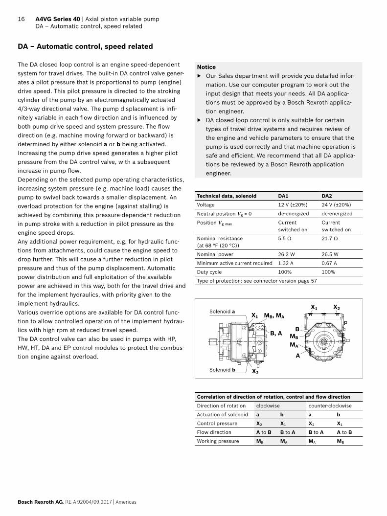
DA – Automatic control, speed related
The DA closed loop control is an engine speed-dependent system for travel drives. The built-in DA control valve gener-ates a pilot pressure that is proportional to pump (engine) drive speed. This pilot pressure is directed to the stroking cylinder of the pump by an electromagnetically actuated 4/3-way directional valve. The pump displacement is infi-nitely variable in each flow direction and is influenced by both pump drive speed and system pressure. The flow direction (e.g. machine moving forward or backward) is determined by either solenoid a or b being activated. Increasing the pump drive speed generates a higher pilot pressure from the DA control valve, with a subsequent increase in pump flow.Depending on the selected pump operating characteristics, increasing system pressure (e.g. machine load) causes the pump to swivel back towards a smaller displacement. An overload protection for the engine (against stalling) is achieved by combining this pressure-dependent reduction in pump stroke with a reduction in pilot pressure as the engine speed drops.Any additional power requirement, e.g. for hydraulic func-tions from attachments, could cause the engine speed to drop further. This will cause a further reduction in pilot pressure and thus of the pump displacement. Automatic power distribution and full exploitation of the available power are achieved in this way, both for the travel drive and for the implement hydraulics, with priority given to the implement hydraulics.Various override options are available for DA control func-tion to allow controlled operation of the implement hydrau-lics with high rpm at reduced travel speed.The DA control valve can also be used in pumps with HP, HW, HT, DA and EP control modules to protect the combus-tion engine against overload.
Notice ▶ Our Sales department will provide you detailed infor-
mation. Use our computer program to work out the input design that meets your needs. All DA applica-tions must be approved by a Bosch Rexroth applica-tion engineer.
▶ DA closed loop control is only suitable for certain types of travel drive systems and requires review of the engine and vehicle parameters to ensure that the pump is used correctly and that machine operation is safe and efficient. We recommend that all DA applica-tions be reviewed by a Bosch Rexroth application engineer.
Technical data, solenoid DA1 DA2
Voltage 12 V (±20%) 24 V (±20%)
Neutral position Vg = 0 de-energized de-energized
Position Vg max Current switched on
Current switched on
Nominal resistance (at 68 °F (20 °C))
5.5 Ω 21.7 Ω
Nominal power 26.2 W 26.5 W
Minimum active current required 1.32 A 0.67 A
Duty cycle 100% 100%
Type of protection: see connector version page 57
B
A
MB
MA
X1 X2
MB, MA
X2
X1
B, A
Solenoid a
Solenoid b
Correlation of direction of rotation, control and flow direction
Direction of rotation clockwise counter-clockwise
Actuation of solenoid a b a b
Control pressure X2 X1 X2 X1
Flow direction A to B B to A B to A A to B
Working pressure MB MA MA MB

Americas | RE-A 92004/09.2017, Bosch Rexroth AG
Axial piston variable pump | A4VG Series 40 DA – Automatic control, speed related
17
DA..1 − DA control valve, fixed settingPilot pressure is generated in relation to drive speed.
▼ Circuit diagram
S
R
T1
T2
MB B
MA A
X1 X2
ba
MH PS
G
YST
DA..5 − DA control valve, fixed setting and brake inch valve mountedOnly for pumps with DA control module.Version with pressure reducing valve.Permits reduction of the pilot pressure, independently of the drive speed via hydraulic control (port Z).Control at port Z by means of brake fluid based on min-eral oil.Maximum permissible pilot pressure at port Z: 1150 psi (80 bar)
▼ Circuit diagram
RZ
T1
T2
MB B
MA A
X1
X2
ba
MH PS
G S
YST
DA..6 − DA control valve, fixed setting, ports for pilot control device as inch valveAny reduction of the pilot pressure possible, independent of the drive speed is achieved by the mechanical actuation of the pilot control device. The pilot control device is installed separately from the pump (for example in the driver’s cabin) and connected to the pump by two hydraulic control lines via ports PS and YST.A suitable pilot control device must be ordered separately and is not included in the scope of delivery.
▼ Circuit diagram
S
R
T1
T2
MB B
MA A
X1 X2
MH PS
G
YST
ba

Bosch Rexroth AG, RE-A 92004/09.2017 | Americas
18 A4VG Series 40 | Axial piston variable pumpEP – Proportional control, electric
EP – Proportional control, electric
The output flow of the pump is infinitely variable between 0 and 100%, proportional to the electrical current supplied to solenoid a or b.The electrical energy is converted into a force acting on the control spool. This control spool then directs control oil into and out of the stroking cylinder to adjust pump displacement as required.A feedback lever connected to the stroking piston maintains the pump flow for any given current within the control range.If the pump is also equipped with a DA control valve (see page 16), automotive operation is possible for travel drives.
I [mA]
EP1, 3
EP2, 4
I [mA]
0.2 0.4 0.6 0.8 1.00.40.60.81.0
12001000800600400200
000.2 Vg
Vg max
Vg
Vg max 200400600800
10001200
EP2, 4
EP1, 3
(Solenoid a)
(Solenoid b)
NoticeThe proportional solenoids in version EP1/EP2 do not have manual override. Proportional solenoids with manual override and spring return are available on request (version EP3/EP4).
Technical data, solenoid EP1, 3 EP2, 4
Voltage 12 V (±20%) 24 V (±20%)
Control current
Start of control at Vg = 0 400 mA 200 mA
End of control at Vg max 1200 mA 600 mA
Current limit 1.54 A 0.77 A
Nominal resistance (at 68 °F (20 °C)) 5.5 Ω 22.7 Ω
Dither
Frequency 100 Hz 100 Hz
minimum oscillation range1) 240 mA 120 mA
Duty cycle 100% 100%
Type of protection: see connector version page 57
Various BODAS controllers with application software and amplifiers are available for controlling the proportional solenoids.Further information can also be found on the Internet at www.boschrexroth.com/mobile-electronics
▼ Circuit diagram
S
R
T1
T2
MB B
MA A
X1 X2
a b
MH PS
G
YST
B, AB
A
MB
MA
X1 X2MB, MA
X2
X1Solenoid a
Solenoid b
Correlation of direction of rotation, control and flow direction
Direction of rotation clockwise counter-clockwise
Actuation of sole-noid
a b a b
Control pressure X1 X2 X1 X2
Flow direction B to A A to B A to B B to A
Working pressure MA MB MB MA
1) Minimum required oscillation range of the control current ΔIp-p (peak to peak) within the respective control range (start of control to end of control)
Americas | RE-A 92004/09.2017, Bosch Rexroth AG
Axial piston variable pump | A4VG Series 40 EZ – Two-point control, electric
19
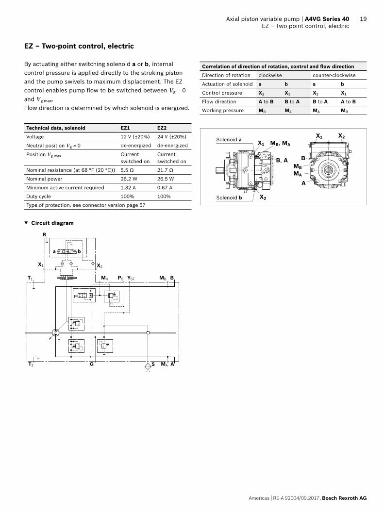
EZ – Two-point control, electric
By actuating either switching solenoid a or b, internal control pressure is applied directly to the stroking piston and the pump swivels to maximum displacement. The EZ control enables pump flow to be switched between Vg = 0 and Vg max. Flow direction is determined by which solenoid is energized.
Technical data, solenoid EZ1 EZ2
Voltage 12 V (±20%) 24 V (±20%)
Neutral position Vg = 0 de-energized de-energized
Position Vg max Current switched on
Current switched on
Nominal resistance (at 68 °F (20 °C)) 5.5 Ω 21.7 Ω
Nominal power 26.2 W 26.5 W
Minimum active current required 1.32 A 0.67 A
Duty cycle 100% 100%
Type of protection: see connector version page 57
▼ Circuit diagram
S
R
T1
T2
MB B
MA A
X1 X2
ba
MH PS
G
YST
Correlation of direction of rotation, control and flow direction
Direction of rotation clockwise counter-clockwise
Actuation of solenoid a b a b
Control pressure X2 X1 X2 X1
Flow direction A to B B to A B to A A to B
Working pressure MB MA MA MB
X1
B, A
MB, MAX1
X2
B
A
MBMA
X2
Solenoid b
Solenoid a

Bosch Rexroth AG, RE-A 92004/09.2017 | Americas
20 A4VG Series 40 | Axial piston variable pumpET – Electric control, direct operated
ET – Electric control, direct operated
The output flow of the pump is infinitely variable between 0 and 100%. Depending on the preselected current I at solenoids a and b of the pressure reducing valves, the stroking cylinder of the pump is proportionally supplied with control pressure. The pump displacement that arises at a certain control current is dependent on the speed and working pressure of the pump. A different flow direction is associated with each pressure reducing valve. Maximum permissible control pressure: 580 psi (40 bar).
Technical data, solenoid ET5 ET6
Voltage 12 V (±20%) 24 V (±20%)
Current limit 1.54 A 0.77 A
Nominal resistance (at 68 °F (20 °C)) 5.5 Ω 22.7 Ω
Dither
Frequency 100 Hz 100 Hz
minimum oscillation range1) 240 mA 120 mA
Duty cycle 100% 100%
Type of protection: see connector version page 57
▼ Circuit diagram
R
a b
X1 X2
T1 MH PS YST MB B
T2 G S MA A
Correlation of direction of rotation, control and flow direction
Direction of rotation clockwise counter-clockwise
Actuation of solenoid a b a b
Control pressure (in X3, X4 optional)
X1 X2 X1 X2
X3 X4 X3 X4
Flow direction B to A A to B A to B B to A
Working pressure MA MB MB MA
Solenoid b
MB,MAX1 B, A
X2
X1
B
A
MB
MA
X2
Solenoid b
Solenoid a
1) Minimum required oscillation range of the control current ΔIp-p (peak to peak) within the respective control range (start of control to end of control)
21
RE-A 92004/09.2017, Bosch Rexroth AG
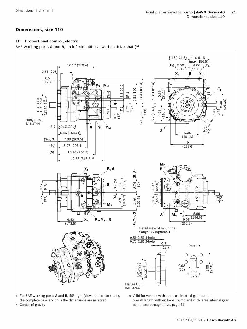
Axial piston variable pump | A4VG Series 40 Dimensions, size 110
Dimensions [inch (mm)]
Dimensions, size 110
EP – Proportional control, electricSAE working ports A and B, on left side 45° (viewed on drive shaft)1)
7.34
(18
6.4)
7.89 (200.5)
6.46 (164.2)2)
12.53 (318.3)3)
8.07 (205.1)
10.18 (258.5)
1.77
(45)
1.2(
30.5
)
3.86
(98)
0.79 (20)
0.5 (12.7)
0.71
(18)
10.17 (258.4)
5.02(127.5)
0.59
(15)
5.91
(150
)
(⌀15
2.4
-0.0
63)
0
(T1)
(YST, G)
(PS)
(S)
(YST
)
(G)
(T1)
(PS)
(S)Flange D6
SAE J744
DIA
6.00
0D
IA5.
998
4.58
(116
.3)
6.36(161.6)
6.36
(161
.6)
9(228.6)
max. 6.16 (max. 156.5)
0.83
(21)
0.9
9(2
5.1)
2)
7.18
(18
2.4)
4.86(123.5)
5.18(131.5)
3.58(91)
0.83
(21)
5.2
(132
)
(T2) (T1)
2.91
(74)
5.69(144.5)9.95
(252.7)
3.37
(85.
5)
1.09
(27.
8)0.98(25)
2.25(57.2)
0.59 (15) 4-hole0.71 (18) 2-hole 0.5
(12.7)
(⌀12
7-0.
063)
0
Detail view of mounting flange C6 (optional)
Detail X
Flange C6SAE J744
3.37
(85.
5)
DIA
5.00
0D
IA4.
998
3.27
(83)
4.8
6(1
23.5
)
0.2
(5)
3.
74
(95)
6.83(173.5)
4.3
(109
.2)
3.27
(83)
(B, A
)(P
S,Y S
T, G
)
4.3
(109
.2)
(S)
BMB
PS, YST, G
MH
S
T2
B, A
S
MH
PS
YSTG
T1
X
T1
X1 R X2
MA T2A
X1
X2
R
1) For SAE working ports A and B, 45° right (viewed on drive shaft), the complete case and thus the dimensions are mirrored.
2) Center of gravity
3) Valid for version with standard internal gear pump, overall length without boost pump and with large internal gear pump, see through drive, page 41
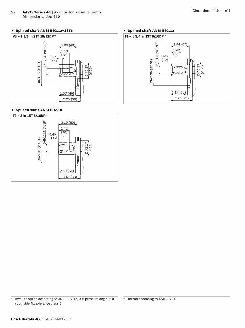
22 A4VG Series 40 | Axial piston variable pumpDimensions, size 110
Bosch Rexroth AG, RE-A 92004/09.2017
Dimensions [inch (mm)]
▼ Splined shaft ANSI B92.1a–1976 ▼ Splined shaft ANSI B92.1aV8 ‒ 1 3/8 in 21T 16/32DP1) T1 ‒ 1 3/4 in 13T 8/16DP1)
7/16
-14U
NC
-2B
2)
2.20 (56)
DIA
3.98
(⌀
101)
1.10(28)
1.57 (40)
DIA
2.17
(⌀55
)
1.89 (48)
0.37(9.5)
5/8-
11U
NC
-2B
2)
2.95 (75)
DIA
3.98
(⌀
101)
1.42(36)
2.17 (55)
DIA
2.17
(⌀55
)
2.64 (67)
0.47(12)
▼ Splined shaft ANSI B92.1aT2 ‒ 2 in 15T 8/16DP1)
5/8-
11U
NC
-2B
2)
3.46 (88)
DIA
3.98
(⌀
101)
1.42(36)
2.60 (66)
DIA
2.17
(⌀55
)
3.15 (80)
0.45(11.4)
1) Involute spline according to ANSI B92.1a, 30° pressure angle, flat root, side fit, tolerance class 5
2) Thread according to ASME B1.1

23
RE-A 92004/09.2017, Bosch Rexroth AG
Axial piston variable pump | A4VG Series 40 Dimensions, size 110
Dimensions [inch (mm)]
Ports Standard Size pmax [psi (bar)]3)
State10)
A, B9) Working portFastening thread, screw grade 8 with hardened washer
SAEJ5184) ASME B1.1
1 in 7/16-14UNC; 0.87 (22) deep
7250 (500) O
S Suction port ISO 119267) 1 5/8-12UN-2B; 0.79 (20) deep 75 (5) O5)
T1 Drain port ISO 119267) 1 5/16-12UN-2B; 0.79 (20) deep 45 (3) O6)
T2 Drain port ISO 119267) 1 5/16-12UN-2B; 0.79 (20) deep 45 (3) X6)
R Air bleed port ISO 119267) 9/16-18UNF-2B; 0.51 (13) deep 45 (3) X
X1, X2 Control pressure port (upstream of orifice) ISO 119267) 9/16-18UNF-2B; 0.51 (13) deep 580 (40) X
X3, X48) Stroking chamber pressure port ISO 119267) 9/16-18UNF-2B; 0.51 (13) deep 580 (40) X
G Boost pressure port inlet ISO 119267) 7/8-14UNF-2B; 0.67 (17) deep 580 (40) X
PS Pilot pressure port inlet ISO 119267) 3/4-16UNF-2B; 0.59 (15) deep 580 (40) X
PS Pilot pressure port inlet (DA..6 only) ISO 119267) 3/4-16UNF-2B; 0.59 (15) deep 580 (40) O
YST Pilot pressure port outlet ISO 119267) 9/16-18UNF-2B; 0.51 (13) deep 580 (40) X
YST Pilot pressure port outlet (DA..6 only) ISO 119267) 9/16-18UNF-2B; 0.51 (13) deep 580 (40) O
MA, MB Measuring port pressure A, B ISO 119267) 9/16-18UNF-2B; 0.51 (13) deep 7250 (500) X
MH Measuring port, high pressure ISO 119267) 9/16-18UNF-2B; 0.51 (13) deep 7250 (500) X
Z Pilot pressure port (inch signal DA..5 only) ISO 119267) 3/8-24UNF-2B; 0.39 (10) deep 1150 (80) O
3) Depending on the application, momentary pressure peaks can oc-cur. Keep this in mind when selecting measuring devices and fit-tings.
4) Only dimensions according to SAE J518.5) Plugged for external boost pressure supply.6) Depending on installation position, T1 or T2 must be connected
(see also installation instructions on page 60).
7) The countersink can be deeper than as specified in the standard.8) Optional, see page 519) For the maximum utilization of pressure, only grade 8 screws and
hardened washers are to be used to tighten the SAE flange shells.10) O = Must be connected (plugged when delivered)
X = Plugged (in normal operation)

24 A4VG Series 40 | Axial piston variable pumpDimensions, size 110
Bosch Rexroth AG, RE-A 92004/09.2017
Dimensions [inch (mm)]
▼ HW – Proportional control, hydraulic, mechanical servo ▼ EZ – Two-point control, electric
Version with neutral position switch, HW8
(63) 2.48
1.06(27)
(50) 1.97
0.31
(8)
0.35(9)
DIA0.31(⌀8)
7.79
(197
.8)
0.79
(20)
2.68
(68)
a
b 36.5° ±1°
36.5
°±1°
3.95
(100
.4)
3.95
(100
.4)
5.91
(150
)
10.25(260.4)
▼ ET – Electric control, direct operated, two DRE
4.3
(109
.2)
4.3
(109
.2)
5.96
(151
.5)
10.17(258.4)
DA control valve
▼ DA..1 – fixed setting ▼ DA..5 – fixed setting and inch valve mounted
max
. 7.2
2(m
ax. 1
83.5
)
3.95
(100
.4)
10.28 (261)
0.20 (5)
3.95
(100
.4)
10.25 (260.4)
5.91
(150
)
R
max
. 7.2
2(m
ax. 1
83.5
)
max
. 3.2
1(m
ax. 8
1.5)
5.23(132.9)
6.83(173.5)
3.95
(100
.4)
10.28 (261)
0.20 (5)
3.95
(100
.4)
10.25 (260.4)4.7
(119.4)
5.91
(150
) 9.06
(230
)
3.11
(79)
4.35
(110
.5)
ZX2
X1

25
RE-A 92004/09.2017, Bosch Rexroth AG
Axial piston variable pump | A4VG Series 40 Dimensions, size 125
Dimensions [inch (mm)]
Dimensions, size 125
EP – Proportional control, electricSAE working ports A and B, on left side 45° (viewed on drive shaft)1)
BMB
PS, YST, G
MH
S
T2
B, A
S
MH
PS
YSTG
T1
X
T1
X1 R X2
MA T2A
X1
X2
R
7.34
(18
6.4)
7.89 (200.5)
6.46 (164.2)2)
12.70 (322.7)3)
8.07 (205.1)
10.18 (258.5)
1.77
(45)
1.2(
30.5
)
3.86
(98)
0.79 (20)
0.5 (12.7)
0.71
(18)
10.17 (258.4)
5.02(127.5)
0.59
(15)
5.91
(150
)
(⌀15
2.4 -
0.06
3)0
(T1)
(YST, G)
(PS)
(S)
(YST
)
(G)
(T1)
(PS)
(S)Flange D6
SAE J744
DIA
6.00
0D
IA5.
998
4.58
(116
.3)
6.36(161.6)
6.36
(161
.6)
9(228.6)
max. 6.16 (max. 156.5)
0.83
(21)
0.9
9(2
5.1)
2)
7.18
(18
2.4)
4.86(123.5)
5.18(131.5)
3.58(91)
0.83
(21)
5.2
(132
)
(T2) (T1)
2.91
(74)
5.69(144.5)
9.95(252.7)
3.37
(85.
5)
0.59 (15) 4-hole0.71 (18) 2-hole
0.5 (12.7)
(⌀12
7-0.
063)
0
Detail view of mounting flange C6 (optional)
Detail X
Flange C6SAE J744
3.37
(85.
5)
DIA
5.00
0D
IA4.
998
3.27
(83)
4.8
6(1
23.5
)
0.2
(5)
3.
74
(95)
6.83(173.5)
4.3
(109
.2)
3.27
(83)
(B, A
)(P
S,Y S
T, G
)
4.3
(109
.2)
(S)
1.09
(27.
8)0.98(25)
2.25(57.2)
⌀
1) For SAE working ports A and B, 45° right (viewed on drive shaft), the complete case and thus the dimensions are mirrored.
2) Center of gravity
3) Valid for version with standard internal gear pump, overall length without boost pump see through drive, page 41.

26 A4VG Series 40 | Axial piston variable pumpDimensions, size 125
Bosch Rexroth AG, RE-A 92004/09.2017
Dimensions [inch (mm)]
▼ Splined shaft ANSI B92.1a ▼ Splined shaft ANSI B92.1aT1 ‒ 1 3/4 in 13T 8/16DP1) T2 ‒ 2 in 15T 8/16DP1)
5/8-
11U
NC
-2B
2)
2.95 (75)
DIA
3.98
(⌀
101)
1.42(36)
2.17 (55)D
IA2.
17(⌀
55)
2.64 (67)
0.47(12)
5/8-
11U
NC
-2B
2)
3.46 (88)
DIA
3.98
(⌀
101)
1.42(36)
2.60 (66)
DIA
2.17
(⌀55
)
3.15 (80)
0.45(11.4)
Ports Standard Size pmax [psi (bar)]3)
State10)
A, B9) Working portFastening thread, screw grade 8 with hardened washer
SAEJ5184) ASME B1.1
1 in 7/16-14UNC; 0.87 (22) deep
7250 (500) O
S Suction port ISO 119267) 1 5/8-12UN-2B; 0.79 (20) deep 75 (5) O5)
T1 Drain port ISO 119267) 1 5/16-12UN-2B; 0.79 (20) deep 45 (3) O6)
T2 Drain port ISO 119267) 1 5/16-12UN-2B; 0.79 (20) deep 45 (3) X6)
R Air bleed port ISO 119267) 9/16-18UNF-2B; 0.51 (13) deep 45 (3) X
X1, X2 Control pressure port (upstream of orifice) ISO 119267) 9/16-18UNF-2B; 0.51 (13) deep 580 (40) X
X3, X48) Stroking chamber pressure port ISO 119267) 9/16-18UNF-2B; 0.51 (13) deep 580 (40) X
G Boost pressure port inlet ISO 119267) 7/8-14UNF-2B; 0.67 (17) deep 580 (40) X
PS Pilot pressure port inlet ISO 119267) 3/4-16UNF-2B; 0.59 (15) deep 580 (40) X
PS Pilot pressure port inlet (DA..6 only) ISO 119267) 3/4-16UNF-2B; 0.59 (15) deep 580 (40) O
YST Pilot pressure port outlet ISO 119267) 9/16-18UNF-2B; 0.51 (13) deep 580 (40) X
YST Pilot pressure port outlet (DA..6 only) ISO 119267) 9/16-18UNF-2B; 0.51 (13) deep 580 (40) O
MA, MB Measuring port pressure A, B ISO 119267) 9/16-18UNF-2B; 0.51 (13) deep 7250 (500) X
MH Measuring port, high pressure ISO 119267) 9/16-18UNF-2B; 0.51 (13) deep 7250 (500) X
Z Pilot pressure port (inch signal DA..5 only) ISO 119267) 3/8-24UNF-2B; 0.39 (10) deep 1150 (80) O
1) Involute spline according to ANSI B92.1a, 30° pressure angle, flat root, side fit, tolerance class 5
2) Thread according to ASME B1.13) Depending on the application, momentary pressure peaks can oc-
cur. Keep this in mind when selecting measuring devices and fit-tings.
4) Only dimensions according to SAE J518.5) Plugged for external boost pressure supply.
6) Depending on installation position, T1 or T2 must be connected (see also installation instructions on page 60).
7) The countersink can be deeper than as specified in the standard.8) Optional, see page 519) For the maximum utilization of pressure, only grade 8 screws and
hardened washers are to be used to tighten the SAE flange shells.10) O = Must be connected (plugged when delivered)
X = Plugged (in normal operation)

27
RE-A 92004/09.2017, Bosch Rexroth AG
Axial piston variable pump | A4VG Series 40 Dimensions, size 125
Dimensions [inch (mm)]
▼ HW – Proportional control, hydraulic, mechanical servo ▼ EZ – Two-point control, electric
Version with neutral position switch, HW8
(63) 2.48
1.06(27)
(50) 1.97
0.31
(8)
0.35(9)
DIA0.31(⌀8)
7.79
(197
.8)
0.79
(20)
2.68
(68)
a
b 36.5° ±1°
36.5
°±1°
3.95
(100
.4)
3.95
(100
.4)
5.91
(150
)
10.25(260.4)
▼ ET – Electric control, direct operated, two DRE
4.3
(109
.2)
4.3
(109
.2)
5.96
(151
.5)
10.17(258.4)
DA control valve
▼ DA..1 – fixed setting
max
. 7.2
2(m
ax. 1
83.5
)
3.95
(100
.4)
10.28 (261)
0.20 (5)
3.95
(100
.4)
10.25 (260.4)
5.91
(150
)

28 A4VG Series 40 | Axial piston variable pumpDimensions, size 145
Bosch Rexroth AG, RE-A 92004/09.2017
Dimensions [inch (mm)]
Dimensions, size 145
EP – Proportional control, electricSAE working ports A and B, on left side 45° (viewed on drive shaft)1)
6.48(164.5)
1.22
(31)
0.04(1.0)2)
max. 6.16(max. 156.5)
T1
BMB
MA T2A
B, A
T2
MHT1
S
PS
X
PS, YST, G
S YSTG
X1 R X2
R
X1
X2
MH
8.31 (211.2)
6.85 (173.9)2)
13.55 (344.2)3)
11.07 (281.2)
4.73(120.2) (T1)
(G, YST, PS)
(S)
0.79 (20)
0.5 (12.7)
10.38 (263.6)
(⌀15
2.4 -
0.06
3)0
Flange D6SAE J744
DIA
6.00
0D
IA5.
998 8.
17 (
207.
4)
1.97
(50)
4.25
(108
)
0.71
(18)
6.69
(170
)
(G)
(T1)
(PS)
(S)
0.79
(20)
(YST
)
1.1
4(2
8.9)
2)
8.01
(20
3.4)
5.19
(131
.9)
5.37(136.4)
5.73(145.5)
3.94(100)
(T2) (T1)
6.36(161.6)
6.36
(161
.6)
9 (228.6)
0.83
(21)
0.83
(21)
3.86
(98)
5.3
7(1
36.4
)
0.2
(5)
4.
02
(102
)
7.04(178.7)
4.3
(109
.2)
3.86
(98)
(B, A
)(P
S,Y S
T, G
)
4.3
(109
.2)
(S)
2.91
(74)
5.36(136.2)10.91
(277.2)
3.48
(88.
5)3.
48(8
8.5)
Detail X
1.25
(31.
8)1.26(32)
2.63(66.7)
1) For SAE working ports A and B, 45° right (viewed on drive shaft), the complete case and thus the dimensions are mirrored.
2) Center of gravity
3) Valid for version without boost pump and for standard internal gear pump, overall length with large internal gear pump, see through drive, page 41.

29
RE-A 92004/09.2017, Bosch Rexroth AG
Axial piston variable pump | A4VG Series 40 Dimensions, size 145
Dimensions [inch (mm)]
▼ Splined shaft ANSI B92.1a ▼ Splined shaft ANSI B92.1aT1 ‒ 1 3/4 in 13T 8/16DP1) T2 ‒ 2 in 15T 8/16DP1)
DIA
4.37
(⌀
111)
5/8-
11U
NC
-2B
2)
DIA
2.36
(⌀60
)
1.42(36)
2.64 (67)
0.47(12)
2.95 (75)
2.17 (55)
DIA
4.37
(⌀
111)
5/8-
11U
NC
-2B
2)
DIA
2.36
(⌀60
)
1.42(36)
3.15 (80)
0.47(12)
3.46 (88)
2.60 (66)
▼ Splined shaft ANSI B92.1aT3 ‒ 2 1/4 in 17T 8/16DP1)
DIA
4.37
(⌀
111)
3/4-
10U
NC
-2B
2)
DIA
2.36
(⌀60
)
1.65(42)
3.15 (80)
0.49(15)
3.46 (88)
2.60 (66)
1) Involute spline according to ANSI B92.1a, 30° pressure angle, flat root, side fit, tolerance class 5
2) Thread according to ASME B1.1
30 A4VG Series 40 | Axial piston variable pumpDimensions, size 145
Bosch Rexroth AG, RE-A 92004/09.2017
Dimensions [inch (mm)]
Ports Standard Size pmax [psi (bar)]3)
State10)
A, B9) Working portFastening thread, screw grade 8 with hardened washer
SAEJ5184) ASME B1.1
1 1/4 in 1/2-13UNC; 0.75 (19) deep
7250 (500) O
S Suction port ISO 119267) 1 7/8-12UN-2B; 0.79 (20) deep 75 (5) O5)
T1 Drain port ISO 119267) 1 5/8-12UN-2B; 0.77 (19.5) deep 45 (3) O6)
T2 Drain port ISO 119267) 1 5/8-12UN-2B; 0.77 (19.5) deep 45 (3) X6)
R Air bleed port ISO 119267) 9/16-18UNF-2B; 0.51 (13) deep 45 (3) X
X1, X2 Control pressure port (upstream of orifice) ISO 119267) 9/16-18UNF-2B; 0.51 (13) deep 580 (40) X
X1, X2 Control pressure port (upstream of orifice, HT only) ISO 119267) 9/16-18UNF-2B; 0.51 (13) deep 580 (40) O
X3, X48) Stroking chamber pressure port ISO 119267) 9/16-18UNF-2B; 0.51 (13) deep 580 (40) X
G Boost pressure port inlet ISO 119267) 7/8-14UNF-2B; 0.67 (17) deep 580 (40) X
PS Pilot pressure port inlet ISO 119267) 3/4-16UNF-2B; 0.59 (15) deep 580 (40) X
PS Pilot pressure port inlet (DA..6 only) ISO 119267) 3/4-16UNF-2B; 0.59 (15) deep 580 (40) O
YST Pilot pressure port outlet ISO 119267) 9/16-18UNF-2B; 0.51 (13) deep 580 (40) X
YST Pilot pressure port outlet (DA..6 only) ISO 119267) 9/16-18UNF-2B; 0.51 (13) deep 580 (40) O
YHT Pilot pressure port outlet (HT only) ISO 119267) 9/16-18UNF-2B; 0.51 (13) deep 580 (40) O
MA, MB Measuring port pressure A, B ISO 119267) 9/16-18UNF-2B; 0.51 (13) deep 7250 (500) X
MH Measuring port, high pressure ISO 119267) 9/16-18UNF-2B; 0.51 (13) deep 7250 (500) X
Y1, Y2 Pilot pressure port (pilot signal HP only) ISO 119267) 9/16-18UNF-2B; 0.51 (13) deep 580 (40) O
Z Pilot pressure port (inch signal DA..5 only) ISO 119267) 3/8-24UNF-2B; 0.39 (10) deep 1150 (80) O
3) Depending on the application, momentary pressure peaks can occur. Keep this in mind when selecting measuring devices and fittings.
4) Only dimensions according to SAE J518.5) Plugged for external boost pressure supply.6) Depending on installation position, T1 or T2 must be connected
(see also installation instructions on page 60).
7) The countersink can be deeper than as specified in the standard.8) Optional, see page 519) For the maximum utilization of pressure, only grade 8 screws and
hardened washers are to be used to tighten the SAE flange shells.10) O = Must be connected (plugged when delivered)
X = Plugged (in normal operation)

31
RE-A 92004/09.2017, Bosch Rexroth AG
Axial piston variable pump | A4VG Series 40 Dimensions, size 145
Dimensions [inch (mm)]
▼ HP – Proportional control, hydraulic, pilot-pressure related ▼ HW – Proportional control, hydraulic, mechanical servo
8.93(226.9)
6.69
(170
)1.
62(4
1.2)
Y2
Y1
1.62
(41.
2)
Version with neutral position switch, HW8
8.61
(218
.7)
2.48(63)
1.06(27)
1.97(50)
0.31
(8)
0.35(9)
DIA0.31(⌀8)
0.79
(20)
2.68
(68)
36.5° ±1°
36.5
°±1°
a
b
▼ HT – Hydraulic control, direct operated ▼ EZ – Two-point control, electric
X1
X2 YHT
1.57
(40)
7.63(193.7)
3.86
(98)
7.04(178.7)
8.01
(203
.4)
3.86
(98)
3.9
5(1
00.4
)6.
69(1
70)
3.95
(100
.4)
10.46(265.6)
▼ ET – Electric control, direct operated, two DRE
4.3
(109
.2)
4.3
(109
.2)
6.75
(171
.5)
10.38(263.6)

32 A4VG Series 40 | Axial piston variable pumpDimensions, size 175
Bosch Rexroth AG, RE-A 92004/09.2017
Dimensions [inch (mm)]
Dimensions, size 175
EP – Proportional control, electricSAE working ports A and B, on left side 45° (viewed on drive shaft)1)
1.22
(31)
6.48(164.5)
0.08 (2.0)2)
max. 6.16(max. 156.5)
T2
MH
S
PS
YST XG
T1X1 R
T1
X2
B, A
S
MB
B
MA T2APS, YST, G
MH
R
X2
X1
9.09 (231)
6.98 (177.3)2)
14.46 (367.3)3)
11.85 (301)
5.51(140) (T1)
(G, YST, PS)
(S)
0.79 (20)
0.63 (15.9)
11.16(283.4)
(⌀16
5.1
-0.0
63)
0
Flange E4SAE J744
DIA
6.50
0D
IA6.
498 8.
17 (
207.
4)
1.97
(50)
4.25
(108
)
0.71
(18)
6.69
(17
0)
(G)
(T1)
(PS)
(S)
0.79
(20)
(YST
)
1.05
(26
.7)2)
8.01
(20
3.4)
5.44
(138
.1)
5.37(136.4)
5.73(145.5)
3.94(100)
(T2) (T1)
8.84
(224
.5)
8.84 (224.5) 0.83
(21)
3.86
(98)
5.3
7(1
36.4
)
0.2
(5)
4.
02
(102
)
7.81(198.5)
4.3
(109
.2)
3.86
(98)
(B, A
)(P
S,Y S
T, G
)
4.3
(109
.2)
(S)
2.91
(74)
6.14(156)11.69
(297)
3.48
(88.
5)3.
48(8
8.5)
(⌀15
2.4 -
0.06
3)0
DIA
6.00
0D
IA5.
998
0.79(20)0.5
(12.7)
Detail X
1.25
(31.
8)1.26(32) 2.63
(66.7)Flange D6SAE J744
Detail view of mounting flange D6 (optional)
1) For SAE working ports A and B, 45° right (viewed on drive shaft), the complete case and thus the dimensions are mirrored.
2) Center of gravity
3) Valid for version with standard internal gear pump, overall length without boost pump and with large internal gear pump, see through drive, page 41.

33
RE-A 92004/09.2017, Bosch Rexroth AG
Axial piston variable pump | A4VG Series 40 Dimensions, size 175
Dimensions [inch (mm)]
▼ Splined shaft ANSI B92.1a ▼ Splined shaft ANSI B92.1aT1 ‒ 1 3/4 in 13T 8/16DP1) T3 ‒ 2 1/4 in 17T 8/16DP1)
5/8-
11U
NC
-2B
2)
DIA
4.37
(⌀
111)
DIA
2.36
(⌀60
)
1.42(36)
2.64 (67)
0.47(12)
2.95 (75)
2.17 (55)
DIA
4.37
(⌀
111)
3/4-
10U
NC
-2B
2)
DIA
2.36
(⌀60
)
1.65(42)
3.15 (80)
0.49(15)
3.46 (88)
2.60 (66)
Ports Standard Size pmax [psi (bar)]3)
State10)
A, B9) Working portFastening thread, screw grade 8 with hardened washer
SAEJ5184) ASME B1.1
1 1/4 in 1/2-13UNC; 0.75 (19) deep
7250 (500) O
S Suction port ISO 119267) 1 7/8-12UN-2B; 0.79 (20) deep 75 (5) O5)
T1 Drain port ISO 119267) 1 5/8-12UN-2B; 0.77 (19.5) deep 45 (3) O6)
T2 Drain port ISO 119267) 1 5/8-12UN-2B; 0.77 (19.5) deep 45 (3) X6)
R Air bleed port ISO 119267) 9/16-18UNF-2B; 0.51 (13) deep 45 (3) X
X1, X2 Control pressure port (upstream of orifice) ISO 119267) 9/16-18UNF-2B; 0.51 (13) deep 580 (40) X
X1, X2 Control pressure port (upstream of orifice, HT only) ISO 119267) 9/16-18UNF-2B; 0.51 (13) deep 580 (40) O
X3, X48) Stroking chamber pressure port ISO 119267) 9/16-18UNF-2B; 0.51 (13) deep 580 (40) X
G Boost pressure port inlet ISO 119267) 7/8-14UNF-2B; 0.67 (17) deep 580 (40) X
PS Pilot pressure port inlet ISO 119267) 3/4-16UNF-2B; 0.59 (15) deep 580 (40) X
PS Pilot pressure port inlet (DA..6 only) ISO 119267) 3/4-16UNF-2B; 0.59 (15) deep 580 (40) O
YST Pilot pressure port outlet ISO 119267) 9/16-18UNF-2B; 0.51 (13) deep 580 (40) X
YST Pilot pressure port outlet (DA..6 only) ISO 119267) 9/16-18UNF-2B; 0.51 (13) deep 580 (40) O
YHT Pilot pressure port outlet (HT only) ISO 119267) 9/16-18UNF-2B; 0.51 (13) deep 580 (40) O
MA, MB Measuring port pressure A, B ISO 119267) 9/16-18UNF-2B; 0.51 (13) deep 7250 (500) X
MH Measuring port, high pressure ISO 119267) 9/16-18UNF-2B; 0.51 (13) deep 7250 (500) X
Y1, Y2 Pilot pressure port (pilot signal HP only) ISO 119267) 9/16-18UNF-2B; 0.51 (13) deep 580 (40) O
Z Pilot pressure port (inch signal DA..5 only) ISO 119267) 3/8-24UNF-2B; 0.39 (10) deep 1150 (80) O
1) Involute spline according to ANSI B92.1a, 30° pressure angle, flat root, side fit, tolerance class 5
2) Thread according to ASME B1.13) Depending on the application, momentary pressure peaks can oc-
cur. Keep this in mind when selecting measuring devices and fit-tings.
4) Only dimensions according to SAE J518.5) Plugged for external boost pressure supply.
6) Depending on installation position, T1 or T2 must be connected (see also installation instructions on page 60).
7) The countersink can be deeper than as specified in the standard.8) Optional, see page 519) For the maximum utilization of pressure, only grade 8 screws and
hardened washers are to be used to tighten the SAE flange shells.10) O = Must be connected (plugged when delivered)
X = Plugged (in normal operation)

34 A4VG Series 40 | Axial piston variable pumpDimensions, size 175
Bosch Rexroth AG, RE-A 92004/09.2017
Dimensions [inch (mm)]
▼ HP – Proportional control, hydraulic, pilot-pressure related ▼ HW – Proportional control, hydraulic, mechanical servo
Y1
Y2
9.71(246.7)
6.69
(170
)1.
62(4
1.2)
1.62
(41.
2)
63
8.58
(217
.8)
2.48(63)
1.06(27)
1.97(50)
0.31
(8)
0.35(9)
DIA0.31(⌀8)
0.79
(20)
2.68
(68) a
b 36.5° ±1°
36.5
°±1°
Version with neutral position switch, HW8
▼ HT – Hydraulic control, direct operated ▼ EZ – Two-point control, electric
YHT
X1
X2
1.57
(40)
8.41(213.5)
3.86
(98)
7.81(198.5)
8.01
(203
.4)
3.86
(98)
3.9
5(1
00.4
)6.
69(1
70)
3.95
(100
.4)
11.24(285.4)
▼ ET – Electric control, direct operated, two DRE
4.3
(109
.2)
4.3
(109
.2)
6.75
(171
.5)
11.16(283.4)

35
RE-A 92004/09.2017, Bosch Rexroth AG
Axial piston variable pump | A4VG Series 40 Dimensions, size 210
Dimensions [inch (mm)]
Dimensions, size 210
EP – Proportional control, electricSAE working ports A and B, on left side 45° (viewed on drive shaft)1)
(YST
)
1.38
(35)
7.34(186.5)
0.08 (2.0)2)
max. 6.75(max. 171.5)
XY
MH
YSt
T2
T1
X1 R X2
G S
PS
T1
B
MB
MA T2A
MH
PSYST, G
B, A
SR
X2
X1
9.41 (239)
7.44 (189)2)
15.26 (387.6)3)
9.72 (247)
5.75(146) (T1)
(G, YST)
(PS)
0.87 (22)
0.63 (15.9)
12(304.9)
(⌀16
5.1
-0
.063
)0
Flange E4SAE J744
DIA
6.50
0D
IA6.
498
12.76 (324)(S)
9.43
(23
9.4)
2.05
(52)
4.8
(122
)
0.59
(15)
7.85
(19
9.5)
(G)
(T1)
(PS)
(S)
0.79
(20)
6.04(153.4)
6.69(170)
4.45(113)
(T2) (T1)
1.22
(31
)2)
9.27
(23
5.4)
5.99
(152
.2) 8.
84(2
24.5
)
8.84 (224.5) 0.83
(21)
3.41
(86.
5)6.57(167)
12.13(308)
4.17
(106
)4.
17(1
06)
4.43
(112
.5)
6.0
4(1
53.4
)
4.37
(1
11)
8.27(210)
4.3
(109
.2)
4.43
(112
.5)
(B, A
)(P
S,Y S
T, G
)
4.3
(109
.2)
1.41
(35.
7)
1.5(38) 2.75
(69.9)
1.5(38) 3.13
(79.4)
1.44
(36.
5)
Detail XPort A, B
Detail YPort S
1) For SAE working ports A and B, 45° right (viewed on drive shaft), the complete case and thus the dimensions are mirrored.
2) Center of gravity
3) Valid for version without boost pump and for standard internal gear pump, overall length with large internal gear pump, see through drive, page 41.

36 A4VG Series 40 | Axial piston variable pumpDimensions, size 210
Bosch Rexroth AG, RE-A 92004/09.2017
Dimensions [inch (mm)]
▼ Splined shaft ANSI B92.1a ▼ Splined shaft ANSI B92.1aT2 ‒ 2 in 15T 8/16DP1) T3 ‒ 2 1/4 in 17T 8/16DP1)
DIA
4.76
(⌀
121)
5/8-
11U
NC
-2B
2)
DIA
2.56
(⌀65
)
1.42(36)
3.15 (80)
0.47(12)
3.46 (88)
2.60 (66)
DIA
4.76
(⌀
121)
3/4-
10U
NC
-2B
2)
DIA
2.56
(⌀65
)
1.65(42)
3.15 (80)
0.49(15)
3.46 (88)
2.60 (66)
Ports Standard Size pmax [psi (bar)]3)
State10)
A, B9) Working portFastening thread, screw grade 8 with hardened washer
SAEJ5184) ASME B1.1
1 1/2 in 5/8-11UNC; 1.14 (29) deep
7250 (500) O
S Suction portFastening thread
SAEJ5184) ASME B1.1
1 1/4 in 1/2-13UNC; 0.94 (24) deep
75 (5) O5)
T1 Drain port ISO 119267) 1 5/8-12UN-2B; 0.77 (19.5) deep 45 (3) O6)
T2 Drain port ISO 119267) 1 5/8-12UN-2B; 0.77 (19.5) deep 45 (3) X6)
R Air bleed port ISO 119267) 9/16-18UNF-2B; 0.51 (13) deep 45 (3) X
X1, X2 Control pressure port (upstream of orifice) ISO 119267) 9/16-18UNF-2B; 0.51 (13) deep 580 (40) X
X3, X48) Stroking chamber pressure port ISO 119267) 9/16-18UNF-2B; 0.51 (13) deep 580 (40) X
G Boost pressure port inlet ISO 119267) 7/8-14UNF-2B; 0.67 (17) deep 580 (40) X
PS Pilot pressure port inlet ISO 119267) 3/4-16UNF-2B; 0.59 (15) deep 580 (40) X
PS Pilot pressure port inlet (DA..6 only) ISO 119267) 3/4-16UNF-2B; 0.59 (15) deep 580 (40) O
YST Pilot pressure port outlet ISO 119267) 9/16-18UNF-2B; 0.51 (13) deep 580 (40) X
YST Pilot pressure port outlet (DA..6 only) ISO 119267) 9/16-18UNF-2B; 0.51 (13) deep 580 (40) O
MA, MB Measuring port pressure A, B ISO 119267) 9/16-18UNF-2B; 0.51 (13) deep 7250 (500) X
MH Measuring port, high pressure ISO 119267) 9/16-18UNF-2B; 0.51 (13) deep 7250 (500) X
Y1, Y2 Pilot pressure port (pilot signal HP only) ISO 119267) 9/16-18UNF-2B; 0.51 (13) deep 580 (40) O
Z Pilot pressure port (inch signal DA..5 only) ISO 119267) 3/8-24UNF-2B; 0.39 (10) deep 1150 (80) O
1) Involute spline according to ANSI B92.1a, 30° pressure angle, flat root, side fit, tolerance class 5
2) Thread according to ASME B1.13) Depending on the application, momentary pressure peaks can oc-
cur. Keep this in mind when selecting measuring devices and fit-tings.
4) Only dimensions according to SAE J518.5) Plugged for external boost pressure supply.
6) Depending on installation position, T1 or T2 must be connected (see also installation instructions on page 60).
7) The countersink can be deeper than as specified in the standard.8) Optional, see page 519) For the maximum utilization of pressure, only grade 8 screws and
hardened washers are to be used to tighten the SAE flange shells.10) O = Must be connected (plugged when delivered)
X = Plugged (in normal operation)

37
RE-A 92004/09.2017, Bosch Rexroth AG
Axial piston variable pump | A4VG Series 40 Dimensions, size 210
Dimensions [inch (mm)]
▼ HP – Proportional control, hydraulic, pilot-pressure related ▼ HW – Proportional control, hydraulic, mechanical servo
3.95(266.2)
7.85
(199
.5)
1.62
(41.
2)1.
62(4
1.2)
Y2
Y1
a
b 36.5° ±1°
36.5
°±1°
9.74
(247
.3)
2.48(63)
1.06(27)
1.97(50)
0.31
(8)
0.35(9)
DIA0.31(⌀8)
0.79
(20)
2.68
(68)
Version with neutral position switch, HW8
▼ EZ – Two-point control, electric
3.9
5(1
00.4
)7.
85(1
99.5
)3.
95(1
00.4
)
12.0(304.9)

38 A4VG Series 40 | Axial piston variable pumpDimensions, size 280
Bosch Rexroth AG, RE-A 92004/09.2017
Dimensions [inch (mm)]
Dimensions, size 280
EP – Proportional control, electricSAE working ports A and B, on left side 45° (viewed on drive shaft)1)
(YST
)
1.38
(35)
7.34(186.5)
0.04 (1.0)2)
max. 6.75(max. 171.5)
X
Y
S
T1 PS
G
MH
YST
T1
T2
X1 R X2
S
R
B, A
MH
PSYST, G
MB
MA
B
A T2X2
X1
10.23 (259.9)
8.46 (215)2)
16.24 (412.6)3)
10.55 (267.9)
6.57(166.9) (T1)
(G, YST)
(PS)
0.87 (22)
0.63 (15.9)
12.74(323.7)
(⌀16
5.1
-0
.063
)0
Flange E4SAE J744
DIA
6.50
0D
IA6.
498
13.58 (344.9)(S)
9.43
(23
9.4)
2.05
(52)
4.8
(122
)
0.59
(15)
7.85
(19
9.5)
(G)
(T1)
(PS)
(S)
0.79
(20)
3.41
(86.
5)7.4(187.9)
12.95(328.9)
4.17
(106
)4.
17(1
06)
1.41
(35.
7)1.5(38) 2.75
(69.9)
1.5(38) 3.13
(79.4)
1.44
(36.
5)
Detail X(Port A, B)
Detail Y(Port S)
4.43
(112
.5)
6.0
4(1
53.4
)
4.37
(1
11)
9.09(230.9)
4.3
(109
.2)
4.43
(112
.5)
(B, A
)(P
S,Y S
T, G
)
4.3
(109
.2)
6.04(153.4)
6.69 (170)
4.45(113)
(T2) (T1)
1.26
(32
)2)
9.27
(23
5.4)
5.99
(152
.2) 8.
84(2
24.5
)
8.84 (224.5) 0.83
(21)
1) For SAE working ports A and B, 45° right (viewed on drive shaft), the complete case and thus the dimensions are mirrored.
2) Center of gravity
3) Valid for version with standard internal gear pump, overall length without boost pump see through drive, page 41.

39
RE-A 92004/09.2017, Bosch Rexroth AG
Axial piston variable pump | A4VG Series 40 Dimensions, size 280
Dimensions [inch (mm)]
▼ Splined shaft ANSI B92.1a ▼ Splined shaft ANSI B92.1aT2 ‒ 2 in 15T 8/16DP1) T3 ‒ 2 1/4 in 17T 8/16DP1)
DIA
4.76
(⌀
121)
5/8-
11U
NC
-2B
2)
DIA
2.56
(⌀65
)
1.42(36)
3.15 (80)
0.47(12)
3.46 (88)
2.60 (66)
DIA
4.76
(ø1
21)
3/4-
10U
NC
-2B
2)
DIA
2.56
(ø65
)
1.65(42)
3.15 (80)
0.49(15)
3.46 (88)
2.60 (66)
Ports Standard Size pmax [psi (bar)]3)
State10)
A, B9) Working port Fastening thread, screw grade 8 with hardened washer
SAEJ5184) ASME B1.1
1 1/2 in 5/8-11UNC; 1.14 (29) deep
7250 (500) O
S Suction port fastening thread SAEJ5184) ASME B1.1
1 1/2 in 1/2-13UNC; 0.94 (24) deep
75 (5) O5)
T1 Drain port ISO 119267) 1 5/8-12UN-2B; 0.77 (19.5) deep 45 (3) O6)
T2 Drain port ISO 119267) 1 5/8-12UN-2B; 0.77 (19.5) deep 45 (3) X6)
R Air bleed port ISO 119267) 9/16-18UNF-2B; 0.51 (13) deep 45 (3) X
X1, X2 Control pressure port (upstream of orifice) ISO 119267) 9/16-18UNF-2B; 0.51 (13) deep 580 (40) X
X3, X48) Stroking chamber pressure port ISO 119267) 9/16-18UNF-2B; 0.51 (13) deep 580 (40) X
G Boost pressure port inlet ISO 119267) 7/8-14UNF-2B; 0.67 (17) deep 580 (40) X
PS Pilot pressure port inlet ISO 119267) 3/4-16UNF-2B; 0.59 (15) deep 580 (40) X
PS Pilot pressure port inlet (DA..6 only) ISO 119267) 3/4-16UNF-2B; 0.59 (15) deep 580 (40) O
YST Pilot pressure port outlet ISO 119267) 9/16-18UNF-2B; 0.51 (13) deep 580 (40) X
YST Pilot pressure port outlet (DA..6 only) ISO 119267) 9/16-18UNF-2B; 0.51 (13) deep 580 (40) O
MA, MB Measuring port pressure A, B ISO 119267) 9/16-18UNF-2B; 0.51 (13) deep 7250 (500) X
MH Measuring port, high pressure ISO 119267) 9/16-18UNF-2B; 0.51 (13) deep 7250 (500) X
Y1, Y2 Pilot pressure port (pilot signal HP only) ISO 119267) 9/16-18UNF-2B; 0.51 (13) deep 580 (40) O
Z Pilot pressure port (inch signal DA..5 only) ISO 119267) 3/8-24UNF-2B; 0.39 (10) deep 1150 (80) O
1) Involute spline according to ANSI B92.1a, 30° pressure angle, flat root, side fit, tolerance class 5
2) Thread according to ASME B1.13) Depending on the application, momentary pressure peaks can oc-
cur. Keep this in mind when selecting measuring devices and fit-tings.
4) Only dimensions according to SAE J518.5) Plugged for external boost pressure supply.
6) Depending on installation position, T1 or T2 must be connected (see also installation instructions on page 60).
7) The countersink can be deeper than as specified in the standard.8) Optional, see page 519) For the maximum utilization of pressure, only grade 8 screws and
hardened washers are to be used to tighten the SAE flange shells.10) O = Must be connected (plugged when delivered)
X = Plugged (in normal operation)

40 A4VG Series 40 | Axial piston variable pumpDimensions, size 280
Bosch Rexroth AG, RE-A 92004/09.2017
Dimensions [inch (mm)]
▼ HP – Proportional control, hydraulic, pilot-pressure related ▼ HW – Proportional control, hydraulic, mechanical servo
11.30 (287.1)
7.85
(199
.5)
1.62
(41.
2)1.
62(4
1.2)
Y2
Y1
9.74
(247
.3)
a
b 36.5° ±1°
36.5
°±1°
2.48(63)
1.06(27)
1.97(50)
0.31
(8)
0.35(9)
DIA0.31(⌀8)
0.79
(20)
2.68
(68)
Version with neutral position switch, HW8
▼ EZ – Two-point control, electric
3.95
(100
.4)
7.85
(199
.5)
3.95
(100
.4)
12.8(325.7)

41
RE-A 92004/09.2017, Bosch Rexroth AG
Axial piston variable pump | A4VG Series 40 Dimensions, through drive
Dimensions [inch (mm)]
1) The through-drive shaft is only supplied with the fastening thread corresponding to the ordering code designation.
2) Involute spline according to ANSI B92.1a, 30° pressure angle, flat root, side fit, tolerance class 5
3) Mounting hole pattern viewed on through drive with control at top4) O-ring included in the scope of delivery5) Thread according to ASME B1.1
Dimensions, through drive
Flange SAE J7441) Hub for splined shaft2)
Diameter Mounting3) Code Diameter Code 110 125 145 175 210 280
Without through drive ● ● ● ● ● ● 0000
82-2 (A) A1 5/8 in 9T 16/32DP S2 ○ – ● ○ – – A1S2
A2 5/8 in 9T 16/32DP S2 ● ○ ○ ○ ○ ○ A2S2
▼ Without through drive, without boost pump, with standard internal gear pump or with large internal gear pump
M0 − without boost pumpM1 − with standard internal gear pump
M2 − with large internal gear pump
NG M0 M1 M2
110 12.37 12.53 12.70
(314.3) (318.3) (322.7)
125 12.37 12.70 –
(314.3) (322.7) –
145 13.55 13.55 13.68
(344.2) (344.2) (347.5)
175 14.32 14.46 14.s57
(363.8) (367.3) (370.1)
210 15.26 15.26 15.46
(387.6) (387.6) (392.7)
280 16.04 16.24 –
(407.3) (412.6) –
▼ 82-2
(to mounting flange)
− with standard internal gear pump− with large internal gear pump
O-ring 4)
M3
M4
M5
M1M2
A1A2
4.19(106.4)
(⌀82
.55 +
0.01
0)+0
.035
M6
(DIA
3.25
+0.0
004)
+0.0
014
NG M1 M2 M3 M4 M5 M65)
110 12.77 12.93 0.35 0.37 1.36 3/8-16UNC-2B; 0.51 (13) deep(324.3) (328.3) (9) (9.4) (34.6)
125 12.93 − 0.35 0.39 1.38
(328.3) − (9) (10) (35)
145 13.63 13.76 0.35 0.37 1.37 3/8-16UNC-2B; 0.51 (13) deep(346.2) (349.5) (9) (9.3) (34.7)
175 14.54 14.65 0.35 0.36 1.31
(369.3) (372.1) (9) (9.1) (33.4)
210 15.34 15.54 0.35 0.29 1.30 On request
(389.6) (394.7) (9) (7.3) (33)
280 16.36 − 0.38 0.37 1.34
(415.6) − (9.7) (9.4) (34.1)

42 A4VG Series 40 | Axial piston variable pumpDimensions, through drive
Bosch Rexroth AG, RE-A 92004/09.2017
Dimensions [inch (mm)]
1) The through-drive shaft is only supplied with the fastening thread corresponding to the ordering code designation.
2) Involute spline according to ANSI B92.1a, 30° pressure angle, flat root, side fit, tolerance class 5
3) Mounting hole pattern viewed on through drive with control at top4) O-ring included in the scope of delivery5) Thread according to ASME B1.1
Flange SAE J7441) Hub for splined shaft2)
Diameter Mounting3) Code Diameter Code 110 125 145 175 210 280
101-2 (B) B1 7/8 in 13T 16/32DP S4 ○ – ● ○ – – B1S4
B1 1 in 15T 16/32DP S5 ○ – ○ ○ – – B1S5
B2 7/8 in 13T 16/32DP S4 ● ● ● ○ ○ ○ B2S4
B2 1 in 15T 16/32DP S5 ● ● ○ ○ ○ ○ B2S5
B5 7/8 in 13T 16/32DP S4 – – ○ – – – B5S4
▼ 101-2
(to mounting flange)
M1 − with standard internal gear pumpM2 − with large internal gear pump
O-ring4)
M3
M4
M5
B1B2B5
B4
B4
5.75(146)
3.5(89)
3.5
(89)
⌀10
1.6 +
0.01
0+0
.035
M6
DIA
4.0 +
0.00
04+0
.001
4
NG M1 M2 M3 M4 M5 M65)
110 12.89 13.04 0.39 0.43 1.93 1/2-13UNC-2B; 0.63 (16) deep(327.3) (331.2) (10) (10.9) (48.9)
125 13.04 − 0.39 0.43 1.89
(331.2) − (10) (11) (48)
145 13.75 13.88 0.39 0.41 1.59
(349.2) (352.5) (10) (10.3) (40.3)
175 14.66 14.77 0.39 0.41 1.59
(372.3) (375.1) (10) (10.3) (40.3)
210 15.46 15.66 0.39 0.39 1.80 1/2-13UNC-2B; 0.63 (16) deep(392.6) (397.7) (10) (9.8) (45.8)
280 16.48 − 0.39 0.41 1.91
(418.6) − (10) (10.5) (48.5)

43
RE-A 92004/09.2017, Bosch Rexroth AG
Axial piston variable pump | A4VG Series 40 Dimensions, through drive
Dimensions [inch (mm)]
1) The through-drive shaft is only supplied with the fastening thread corresponding to the ordering code designation.
2) Involute spline according to ANSI B92.1a, 30° pressure angle, flat root, side fit, tolerance class 5
3) Mounting hole pattern viewed on through drive with control at top4) O-ring included in the scope of delivery5) Thread according to ASME B1.1
▼ 127-2, 127-2/4
M4
M57.13(181)
4.51
(114
.5)
C4
4.51(114.5)
C4
C1C2
M3
(DIA
5.00
+0.0
004)
+0.0
014
⌀12
7 +0.
010
+0.0
35 M6
M7
(to mounting flange)
M1 − with standard internal gear pumpM2 − with large internal gear pump
O-ring4)
NG M1 M2 M3 M4 M5 M65) 2-hole
110 13.12 13.28 0.55 0.67 2.29 5/8-11UNC-2B; 0.83(21) deep(333.3) (337.3) (14) (16.9) (54.9)
125 On request 0.55 0.43 2.36 On request(14) (10.9) (59.9)
145 13.98 14.11 0.55 0.64 2.49 5/8-11UNC-2B; 0.83(21) deep(355.2) (358.5) (14) (16.3) (63.3)
175 14.89 15.0 0.55 0.64 2.41(378.3) (381.1) (14) (16.3) (61.3)
210 15.89 16.09 1.06 0.56 2.22(403.7) (408.8) (27) (14.2) (56.4)
280 16.72 – 1.06 0.57 2.31(424.6) – (27) (14.4) (58.6)
NG M75) 4-hole
110 On request
145, 175 1/2-13UNC-2B; 0.83(21) deep
▼ 152-4
DIA
6.0 +
0.00
04+0
.001
4
M3
M4
M5
6.36(161.6)
6.36
(161
.6)
D4D4
⌀15
2.4 +
0.01
0+0
.035
M6
(to mounting flange)
M1 − with standard internal gear pumpM2 − with large internal gear pump
O-ring4)NG M1 M2 M3 M4 M5 M65)
145 14.02 14.15 0.55 0.39 2.93 3/4-10UNC-2B;0.87 (22) deep(356.2) (359.5) (14) (10) (74.4)
175 14.93 15.04 0.55 0.70 3.00
(379.3) (382.1) (14) (17.8) (76.3)
210 16.20 16.41 1.02 0.56 3.10
(411.6) (416.7) (26) (14.3) (78.8)
280 17.03 – 1.02 0.57 3.31
(432.5) – (26) (14.5) (84)
Flange SAE J7441) Hub for splined shaft2)
Diameter Mounting3) Code Diameter Code 110 125 145 175 210 280
127-2 (C) C1 1 1/4 in 14T 12/24DP S7 ● – ○ ○ ○ ○ C1S7
C2 1 1/4 in 14T 12/24DP S7 ● ○ ● ● ● ○ C2S7
C2 1 3/8 in 21T 16/32DP V8 ● – ○ ○ – – C2V8
C2 1 3/4 in 13T 8/16DP T1 – – ● ○ – – C2T1
127-4 (C) C4 1 1/4 in 14T 12/24DP S7 ○ – ○ ● – – C4S7
C4 1 3/8 in 21T 16/32DP V8 ○ – – – – – C4V8
152-4 (D) D4 1 3/4 in 13T 8/16DP T1 – – ● ● ● ○ D4T1

44 A4VG Series 40 | Axial piston variable pumpDimensions, through drive
Bosch Rexroth AG, RE-A 92004/09.2017
Dimensions [inch (mm)]
▼ 165-4
M3
M4
M5
DIA
6.5 +
0.00
04+0
.001
4
8.84(224.5)
8.84
(224
.5)
⌀16
5.1 +
0.01
0+0
.035
M6
O-ring4)
(to mounting flange)
M1 − with standard internal gear pumpM2 − with large internal gear pump
NG M1 M2 M3 M4 M5 M65)
175 15.00 15.11 0.67 0.76 3.07 3/4-10UNC-2B; 0.87 (22) deep(381) (383.8) (17) (19.4) (77.9)
210 16.04 16.24 On request
(407.3) (412.4)
280 17.61 – On request
(447.3) –
Flange SAE J7441) Hub for splined shaft2)
Diameter Mounting3) Code Diameter Code 110 125 145 175 210 280
165-4 (E) E4 1 3/4 in 13T 8/16DP T1 – – – ○ ○ ○ E4T12 in 15T 8/16DP T2 – – – – ○ ○ E4T2
1) The through-drive shaft is only supplied with the fastening thread corresponding to the ordering code designation.
2) Involute spline according to ANSI B92.1a, 30° pressure angle, flat root, side fit, tolerance class 5
3) Mounting hole pattern viewed on through drive with control at top4) O-ring included in the scope of delivery5) Thread according to ASME B1.1

Americas | RE-A 92004/09.2017, Bosch Rexroth AG
Axial piston variable pump | A4VG Series 40 Overview of mounting options
45
Overview of mounting options
Through drive1) Mounting option − 2nd pump
Flange Hub for splined shaft
Code A4VG/40NG (shaft)
A4VG/32NG (shaft)
A10VGNG (shaft)
A10VO/3xNG (shaft)
A10V(S)O/5xNG (shaft)
A11VO/1NG (shaft)
External gear pump2)
82-2 (A) 5/8 in A_S2 ‒ ‒ ‒ 18 (U) 10, 18 (U) ‒ AZPF, AZPS NG4 … 28AZPW NG5 … 22
101-2 (B) 7/8 in B_S4 ‒ ‒ 18 (S) 28 (S)45 (U)
28 (S)45 (U)
‒ AZPN-11 NG20 … 25AZPG-22 NG28 … 100
1 in B_S5 ‒ 28 (S) 28, 45 (S) 45 (S) 45 (S)60, 63, 72 (U)
40 (S) ‒
127-2 (C) 1 1/4 in C_S7 ‒ 40, 56, 71 (S) 63 (S) 71 (S)100 (U)
85, 100 (U) 60 (S) ‒
1 3/8 in C2V8 110 (V8) 56, 71 (T) 63 (T) ‒ ‒ 60 (T)
1 3/4 in C2T1 110, 125 (T1) ‒ ‒ ‒ ‒ ‒
127-4 (C) 1 1/4 in C4S7 ‒ ‒ ‒ ‒ 60, 63, 72 (S)85, 100 (U)
‒
1 3/8 in C4V8 110 (V8) ‒ ‒ ‒ ‒ ‒
152-4 (D) 1 3/4 in D4T1 110, 125, 145, 175 (T1)
90, 125 (S) ‒ 140, 180 (S) ‒ 95, 130, 145 (S)
‒
165-4 (E) 1 3/4 in E4T1 175 (T1) 180 (S) ‒ ‒ ‒ 190, 260 (S) ‒
2 in E4T2 210, 280 (T2) ‒ ‒ ‒ ‒ 190 (T)
NoticeThe mounting options listed only apply for drive shaft versions with undercut. Please contact us for drive shafts without undercut.
1) Availability of the individual sizes, see type code on page 4.2) Bosch Rexroth recommends special versions of the gear pumps.
Please contact us.
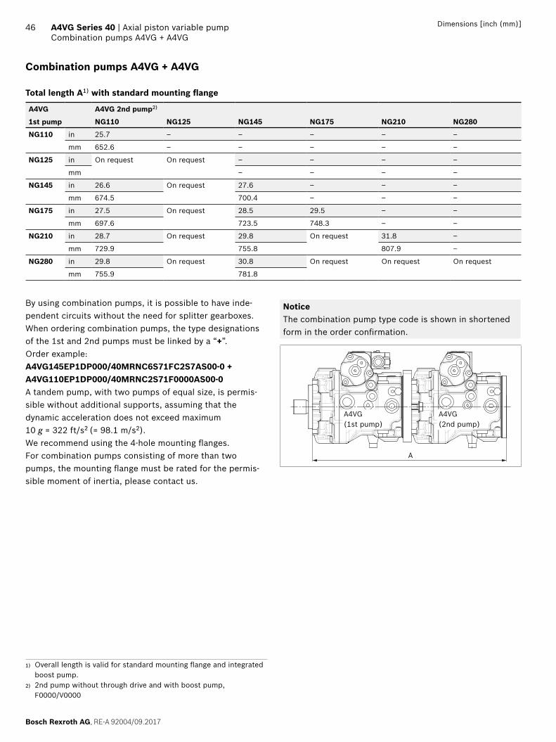
46 A4VG Series 40 | Axial piston variable pumpCombination pumps A4VG + A4VG
Bosch Rexroth AG, RE-A 92004/09.2017
Dimensions [inch (mm)]
Combination pumps A4VG + A4VG
Total length A1) with standard mounting flange
A4VG A4VG 2nd pump2)
1st pump NG110 NG125 NG145 NG175 NG210 NG280
NG110 in 25.7 ‒ ‒ ‒ ‒ ‒
mm 652.6 ‒ ‒ ‒ ‒ ‒
NG125 in On request On request ‒ ‒ ‒ ‒
mm ‒ ‒ ‒ ‒
NG145 in 26.6 On request 27.6 ‒ ‒ ‒
mm 674.5 700.4 ‒ ‒ ‒
NG175 in 27.5 On request 28.5 29.5 ‒ ‒
mm 697.6 723.5 748.3 ‒ ‒
NG210 in 28.7 On request 29.8 On request 31.8 ‒
mm 729.9 755.8 807.9 ‒
NG280 in 29.8 On request 30.8 On request On request On request
mm 755.9 781.8
By using combination pumps, it is possible to have inde-pendent circuits without the need for splitter gearboxes. When ordering combination pumps, the type designations of the 1st and 2nd pumps must be linked by a “+”.Order example:A4VG145EP1DP000/40MRNC6S71FC2S7AS00-0 + A4VG110EP1DP000/40MRNC2S71F0000AS00-0A tandem pump, with two pumps of equal size, is permis-sible without additional supports, assuming that the dynamic acceleration does not exceed maximum 10 g = 322 ft/s2 (= 98.1 m/s2).We recommend using the 4-hole mounting flanges.For combination pumps consisting of more than two pumps, the mounting flange must be rated for the permis-sible moment of inertia, please contact us.
NoticeThe combination pump type code is shown in shortened form in the order confirmation.
A
A4VG (1st pump)
A4VG (2nd pump)
1) Overall length is valid for standard mounting flange and integrated boost pump.
2) 2nd pump without through drive and with boost pump, F0000/V0000

Americas | RE-A 92004/09.2017, Bosch Rexroth AG
Axial piston variable pump | A4VG Series 40 High-pressure relief valves
47
High-pressure relief valves
The two high-pressure relief valves protect the hydrostatic transmission (pump and motor) from overloading. They limit the maximum pressure in the respective high-pressure line and serve simultaneously as boost valves.High-pressure relief valves are not working valves and are only suitable for pressure peaks or high rates of pressure change.
Setting ranges
High-pressure relief valve A and B
Differential pressure setting ∆pHD
Preferred values 5800 psi (400 bar)
5950 psi (410 bar)
6100 psi (420 bar)
6250 psi (430 bar)
6400 psi (440 bar)
6500 psi (450 bar)
6650 psi (460 bar)
6800 psi (470 bar)
Optional values 4350 psi (300 bar)
4650 psi (320 bar)
4950 psi (340 bar)
5200 psi (360 bar)
5500 psi (380 bar)
Settings on high-pressure relief valve A and B
Differential pressure setting ΔpHD = ... psi
Cracking pressure of the HD valve (at qV 1)(pmax = ΔpHD + pSp)
pmax = ... psi
▶ The valve settings are made at n = 1000 rpm and at Vg max (qv 1). There may be deviations in the cracking pressures with other operating parameters.
▶ When ordering, state differential pressure setting in plain text.
▼ Circuit diagram
S
T1
T2
MB B
MA A
X1 X2
MH PS
G
YST
R YHT
High-pressure relief valves
High-pressure relief valve without pressure cut-off
▼ Example
Working pressure
Boost pressure
Differential pressure
pA,B
‒
pSp
=
∆pHD
6500 psi(450 bar)
290 psi(20 bar)
6250 psi(430 bar)
▼ Setting diagram
Wor
king
pre
ssur
e p A
, B a
t po
rt A
, B
Δpdr
ive
desi
gn
Boost pressure
(п = 1000 rpm)
Diff
eren
tial p
ress
ure
p HD
HD
val
ve s
ettin
g Safety
qv max
(n = nmax)
p Sp
pSp
pmax
qv1
≥ 435 psi≥ (30 bar)
High-pressure relief valve with pressure cut-off
▼ Example
Working pressure
Boost pressure
Safety Differential pressure
pA,B
‒
pSp
+ =
∆pHD
6500 psi(450 bar)
290 psi(20 bar)
435 psi(30 bar)
6645 psi(460 bar)
▼ Setting diagram
p Sp
pSp
pmax
qv1 qv max
(n = nmax)
Wor
king
pre
ssur
e p A
, B a
t po
rt A
, B
Δpdr
ive
desi
gn
Boost pressure
Safety Setting valuepressure cut-off
(п = 1000 rpm)
Diff
eren
tial p
ress
ure
p HD
HD
val
ve s
ettin
g
≥ 435 psi≥ (30 bar)

Bosch Rexroth AG, RE-A 92004/09.2017 | Americas
48 A4VG Series 40 | Axial piston variable pumpPressure cut-off
Pressure cut-off
The pressure cut-off is a pressure control which, after reaching the set pressure, adjusts the displacement of the pump back to Vg min.This valve prevents the operation of the high-pressure relief valves when accelerating or decelerating.The high-pressure relief valves protect against the pressure peaks which occur during fast swiveling of the swashplate and limit the maximum pressure in the system.The setting range of the pressure cut-off may be anywhere within the entire working pressure range. However, it must be set 435 psi (30 bar) lower than the setting value of the high-pressure relief valves (see setting diagram, page 47).Please state the setting value of the pressure cut-off in plain text when ordering.
▼ Circuit diagram with pressure cut-off Example: electric control, EP_D
S
R
T1
T2
MB B
MA A
X1 X2
MH PS
G
YST
a bBypass
Pressure cut-off
Bypass function
A connection between the two high-pressure channels A and B can be established using the bypass valve (e.g. for machine towing).
Towing speedThe maximum towing speed is dependent on the gear ratio in the vehicle and must be calculated by the vehicle manu-facturer. The corresponding flow of qV = 7.9 gpm (= 30 l/min) may not be exceeded.
Towing distanceThe vehicle may only be towed out of the immediate danger zone.
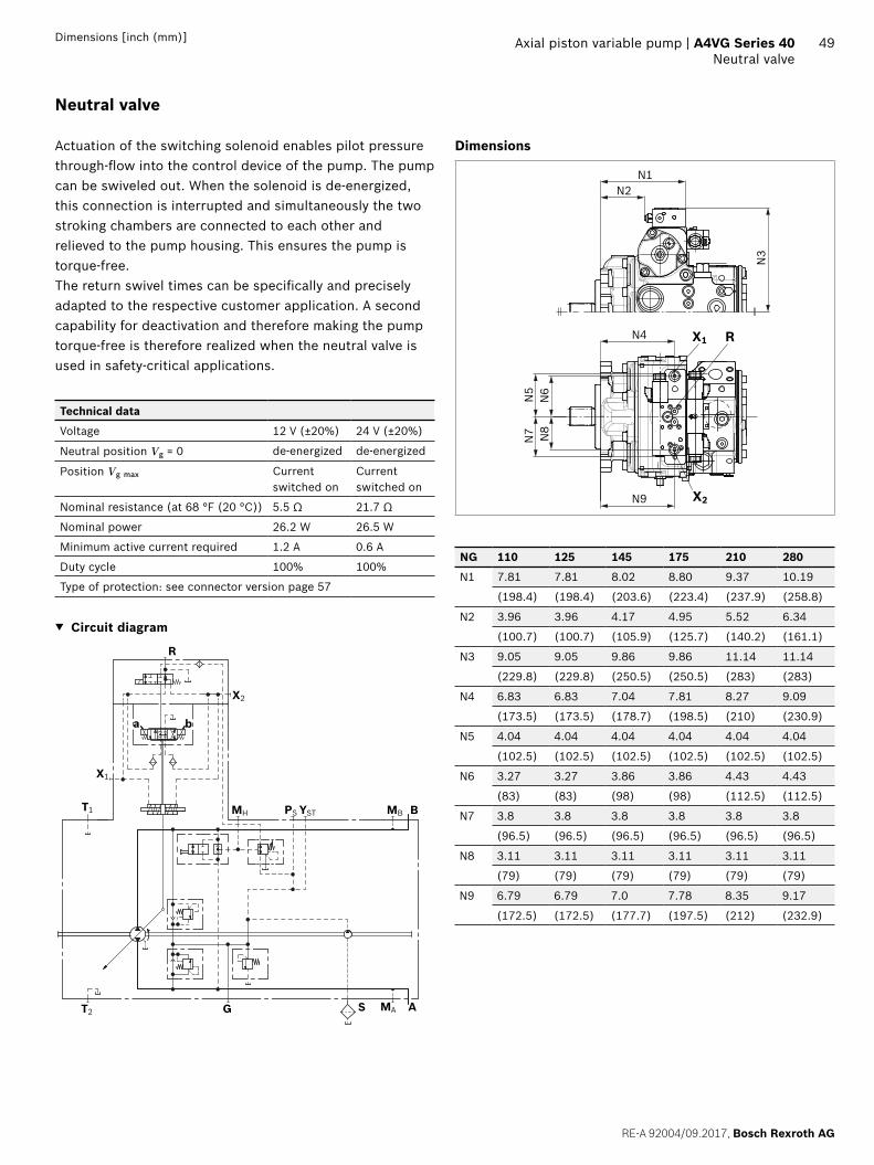
49
RE-A 92004/09.2017, Bosch Rexroth AG
Axial piston variable pump | A4VG Series 40 Neutral valve
Dimensions [inch (mm)]
Neutral valve
Actuation of the switching solenoid enables pilot pressure through-flow into the control device of the pump. The pump can be swiveled out. When the solenoid is de-energized, this connection is interrupted and simultaneously the two stroking chambers are connected to each other and relieved to the pump housing. This ensures the pump is torque-free.The return swivel times can be specifically and precisely adapted to the respective customer application. A second capability for deactivation and therefore making the pump torque-free is therefore realized when the neutral valve is used in safety-critical applications.
Technical data
Voltage 12 V (±20%) 24 V (±20%)
Neutral position Vg = 0 de-energized de-energized
Position Vg max Current switched on
Current switched on
Nominal resistance (at 68 °F (20 °C)) 5.5 Ω 21.7 Ω
Nominal power 26.2 W 26.5 W
Minimum active current required 1.2 A 0.6 A
Duty cycle 100% 100%
Type of protection: see connector version page 57
▼ Circuit diagram
R
X2
a b
X1
T1 MH PS YST MB B
T2 G MA AS
Dimensions
X2
X1
N6
N8
N9
N4
N7
N5
N2N1
N3
R
NG 110 125 145 175 210 280
N1 7.81 7.81 8.02 8.80 9.37 10.19
(198.4) (198.4) (203.6) (223.4) (237.9) (258.8)
N2 3.96 3.96 4.17 4.95 5.52 6.34
(100.7) (100.7) (105.9) (125.7) (140.2) (161.1)
N3 9.05 9.05 9.86 9.86 11.14 11.14
(229.8) (229.8) (250.5) (250.5) (283) (283)
N4 6.83 6.83 7.04 7.81 8.27 9.09
(173.5) (173.5) (178.7) (198.5) (210) (230.9)
N5 4.04 4.04 4.04 4.04 4.04 4.04
(102.5) (102.5) (102.5) (102.5) (102.5) (102.5)
N6 3.27 3.27 3.86 3.86 4.43 4.43
(83) (83) (98) (98) (112.5) (112.5)
N7 3.8 3.8 3.8 3.8 3.8 3.8
(96.5) (96.5) (96.5) (96.5) (96.5) (96.5)
N8 3.11 3.11 3.11 3.11 3.11 3.11
(79) (79) (79) (79) (79) (79)
N9 6.79 6.79 7.0 7.78 8.35 9.17
(172.5) (172.5) (177.7) (197.5) (212) (232.9)
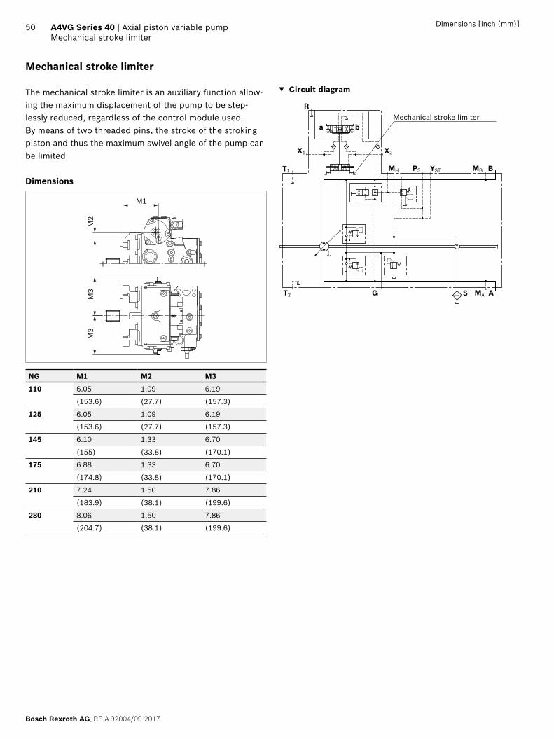
50 A4VG Series 40 | Axial piston variable pumpMechanical stroke limiter
Bosch Rexroth AG, RE-A 92004/09.2017
Dimensions [inch (mm)]
Mechanical stroke limiter
The mechanical stroke limiter is an auxiliary function allow-ing the maximum displacement of the pump to be step-lessly reduced, regardless of the control module used.By means of two threaded pins, the stroke of the stroking piston and thus the maximum swivel angle of the pump can be limited.
Dimensions
M1
M2
M3
M3
NG M1 M2 M3
110 6.05 1.09 6.19
(153.6) (27.7) (157.3)
125 6.05 1.09 6.19
(153.6) (27.7) (157.3)
145 6.10 1.33 6.70
(155) (33.8) (170.1)
175 6.88 1.33 6.70
(174.8) (33.8) (170.1)
210 7.24 1.50 7.86
(183.9) (38.1) (199.6)
280 8.06 1.50 7.86
(204.7) (38.1) (199.6)
▼ Circuit diagram
S
R
T1
T2
MB B
MA A
X1 X2
MH PS
G
YST
a bMechanical stroke limiter

51
RE-A 92004/09.2017, Bosch Rexroth AG
Axial piston variable pump | A4VG Series 40 Stroking chamber pressure port X3 and X4
Dimensions [inch (mm)]
Stroking chamber pressure port X3 and X4
DimensionsT3
T3
T1
T2
X3
X4
NG T1 T2 T3
110 6.37 0.86 5.04
(161.8) (21.8) (128)
125 6.37 0.86 5.04
(161.8) (21.8) (128)
145 6.49 1.04 5.59
(164.9) (26.4) (142)
175 7.27 1.04 5.59
(184.7) (26.4) (142)
210 7.70 1.20 6.54
(195.7) (30.6) (166)
280 8.53 1.20 6.54
(216.6) (30.6) (166)
▼ Circuit diagram
S
R
T1
T2
MB B
MA A
X1 X2
MH PS
G
YST
X3 X4
a b
Ports Standard1) Size pmax [bar]2) State3)
X3, X4 Stroking chamber pressure port ISO 11926 9/16-18UNF-2B; 0.51 (13) deep 40 X
1) The countersink can be deeper than as specified in the standard.2) Depending on the application, momentary pressure peaks can
occur. Keep this in mind when selecting measuring devices and fittings.
3) X = Plugged (in normal operation)

Bosch Rexroth AG, RE-A 92004/09.2017 | Americas
52 A4VG Series 40 | Axial piston variable pumpFiltration in the boost pump suction line
Filtration in the boost pump suction line
Version S
Filter version Suction filter
Recommendation With contamination indicator,with cold start valve
Recommended flow resistance at filter element
At ν = 140 SUS, n = nmax (30 mm2/s, n = nmax)
Δp ≤ 1.5 psi (≤ 0.1 bar)
At ν = 4600 SUS, n = nmax (1000 mm2/s, n = nmax)
Δp ≤ 4.5 psi (≤ 0.3 bar)
Pressure at suction port S
Continuous pS min (ν ≤ 140 SUS) (ν ≤ 30 mm2/s)
≥ 12 psi absolute (≥ 0.8 bar absolute)
Short-term, at a cold start (t < 3 min)
≥ 7.5 psi absolute (≥ 0.5 bar absolute)
Maximum pressure pS max ≤ 75 psi absolute (≤ 5 bar absolute)
Use of version S is preferred. The suction filter is not included in the scope of delivery.
▼ Circuit diagram
S
T1
T2
MB B
MA A
X1 X2
MH PS
G
YST
R YHT
Filtration in the boost pump pressure line
Version DPorts for external boost circuit filtration
Ports
Boost pressure inlet Port Fa
Boost pressure outlet Port Fe
Filter version Boost pressure filter
Recommendation With contamination indicator,with cold start valve
Filter arrangement Separate in the pressure line (inline filter)
Permissible flow resistance at filter element1)
At ν = 140 SUS (30 mm2/s)
Δp ≤ 15 psi (≤ 1 bar)
For cold start Δp ≤ 45 psi (≤ 3 bar)
Notice ▶ Filters with a bypass not recommended. Please con-
tact us for applications with a bypass. ▶ On versions with HT control (with pilot pressure not
from a boost circuit) a filter must be used that fulfills the requirement with regard to filtration of the hydrau-lic fluid (see page 7).
The boost pressure filter is not included in the scope of delivery.
▼ Circuit diagram
S
R
T1
T2
MB B
MA A
X1 X2
MH PS
G
YST FeFa
a b
NoticeBosch Rexroth has a comprehensive filter range. An inline filter such as the 110 LEN (see data sheet 51448) is suitable for charge pressure filtration. Further informa-tions can also be found at www.boschrexroth.com/filter.
1) Valid for entire speed range nmin – nmax
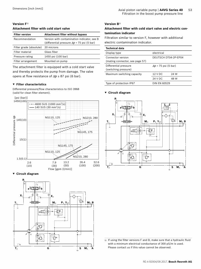
53
RE-A 92004/09.2017, Bosch Rexroth AG
Axial piston variable pump | A4VG Series 40 Filtration in the boost pump pressure line
Dimensions [inch (mm)]
Version F1)
Attachment filter with cold start valve
Filter version Attachment filter without bypass
Recommendation Version with contamination indicator, see B (differential pressure Δp = 75 psi (5 bar)
Filter grade (absolute) 20 microns
Filter material Glass fiber
Pressure rating 1450 psi (100 bar)
Filter arrangement Mounted on pump
The attachment filter is equipped with a cold start valve and thereby protects the pump from damage. The valve opens at flow resistance of Δp ≥ 87 psi (6 bar).
▼ Filter characteristicsDifferential pressure/flow characteristics to ISO 3968 (valid for clean filter element).
Diff
eren
tial p
ress
ure
Δp
Flow [gpm (l/min)]
4600 SUS (1000 mm2/s)140 SUS (30 mm2/s)
2.6 26.413.2 52.61.5(0.1)
15(1)
145(10)
1450(100)
(10) (100)(50) (200)7.9(30)
[psi (bar)]
NG210, 280
NG210, 280
NG145, 175
NG145, 175
NG110, 125
NG110, 125
▼ Circuit diagram
S
R
T1
T2
MB B
MA A
X1 X2
MH PS
G
YST
ba
Version B1)
Attachment filter with cold start valve and electric con-tamination indicatorFiltration similar to version F, however with additional electric contamination indicator.
Technical data
Display type electrical
Connector version (mating connector, see page 57)
DEUTSCH DT04-2P-EP04
Differential pressure (switching pressure)
Δp = 75 psi (5 bar)
Maximum switching capacity 12 V DC 24 W
24 V DC 48 W
Type of protection IP67 DIN EN 60529
▼ Circuit diagram
S
R
T1
T2
MB B
MA A
X1 X2
MH PS
G
YST
ba1 2
1) If using the filter versions F and B, make sure that a hydraulic fluid with a minimum electrical conductance of 300 pS/m is used. Please contact us if this value cannot be observed.

Bosch Rexroth AG, RE-A 92004/09.2017 | Americas
54 A4VG Series 40 | Axial piston variable pumpExternal boost pressure supply
External boost pressure supply
Version EThis variant should be used in versions without integrated boost pump (U).Port S is plugged. The boost pressure supply comes from port G.The filter should be installed separately on port G before the boost pressure supply.To ensure the functional reliability, maintain the required cleanliness level for the boost fluid fed in at port G (see page 7).
▼ Circuit diagram
Fa
R
T1
T2
MB B
MA A
X1 X2
MH PS
G
YST
ba
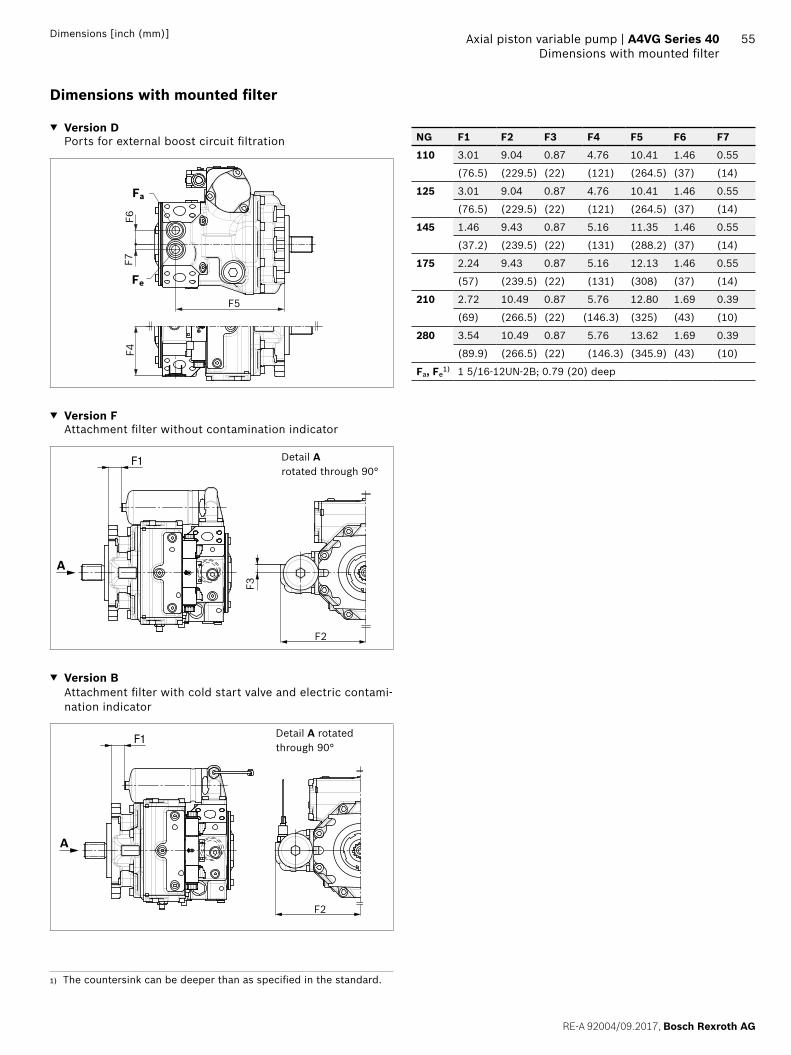
55
RE-A 92004/09.2017, Bosch Rexroth AG
Axial piston variable pump | A4VG Series 40 Dimensions with mounted filter
Dimensions [inch (mm)]
Dimensions with mounted filter
▼ Version D Ports for external boost circuit filtration
Fa
Fe
F4
F5
F7F6
▼ Version F Attachment filter without contamination indicator
Detail A rotated through 90°
F2
F1
F3
A
▼ Version B Attachment filter with cold start valve and electric contami-nation indicator
Detail A rotated through 90°
F2
F1
A
NG F1 F2 F3 F4 F5 F6 F7
110 3.01 9.04 0.87 4.76 10.41 1.46 0.55
(76.5) (229.5) (22) (121) (264.5) (37) (14)
125 3.01 9.04 0.87 4.76 10.41 1.46 0.55
(76.5) (229.5) (22) (121) (264.5) (37) (14)
145 1.46 9.43 0.87 5.16 11.35 1.46 0.55
(37.2) (239.5) (22) (131) (288.2) (37) (14)
175 2.24 9.43 0.87 5.16 12.13 1.46 0.55
(57) (239.5) (22) (131) (308) (37) (14)
210 2.72 10.49 0.87 5.76 12.80 1.69 0.39
(69) (266.5) (22) (146.3) (325) (43) (10)
280 3.54 10.49 0.87 5.76 13.62 1.69 0.39
(89.9) (266.5) (22) (146.3) (345.9) (43) (10)
Fa, Fe1) 1 5/16-12UN-2B; 0.79 (20) deep
1) The countersink can be deeper than as specified in the standard.

56 A4VG Series 40 | Axial piston variable pumpSwivel angle sensor
Bosch Rexroth AG, RE-A 92004/09.2017
Dimensions [inch (mm)]
Swivel angle sensor
The swivel angle sensor is used to detect the swivel angle of axial piston units and thus the displacement using a Hall-effect based sensor IC. The determined measurement value is converted into an analog signal.Please contact us if the swivel angle sensor is used for control.
Characteristics
Supply voltage Ub 10 to 30 V DC
Output voltage Ua 1 V(Vg max)
2.5 V(Vg 0)
4 V(Vg max)
Reverse polarity protection Short-circuit resistant
EMC resistance Details on request
Operating temperature range -40 °F to +240 °F (-40 °C to +115 °C)
Vibration resistance sinusoidal vibration EN 60068-2-6
322 ft/s2 (10 g) / 5 to 2000 Hz
Shock resistance:continuous shock IEC 68-2-29
805 ft/s2 (25 g)
Salt spray resistance (DIN 50 021-SS) 96 h
Type of protection with installed mating connector
IP67 – DIN EN 60529IP69K – DIN 40050-9
Housing material Plastic
Output voltage
Direction of rotation1)
Flow direction
Working pressure
Output voltageat Vg 0
Clockwise B to A MA >2.5 V
A to B MB <2.5 V
Counter- clockwise
A to B MB >2.5 V
B to A MA <2.5 V
▼ Circuit diagram
α U
S
R
T1
T2
MB B
MA A
X1 X2
a b
MH PS
G
YST
Electric swivel angle sensor
Dimensions
A
BC
Y
Output voltage Ua
Detail Y Connector DT04-3P-EP04
GroundSupply voltage Ub
NG A B C
110 2.03 (51.5) 5.86 (148.8) 1.46 (37)
125 2.03 (51.5) 5.86 (148.8) 1.46 (37)
145 2.09 (53.1) 6.33 (160.8) 1.46 (37)
175 2.54 (64.4) 6.33 (160.8) 1.46 (37)
210 2.72 (69) 6.84 (173.8) 1.46 (37)
280 2.96 (75.1) 6.84 (173.8) 1.46 (37)
Mating connector DEUTSCH DT06-3S-EP04
Consisting of DT designation
1 housing DT06-3S-EP04
1 wedge W3S
2 sockets 0462-201-16141
The mating connector is not included in the scope of delivery. This can be supplied by Bosch Rexroth on request (material number R902603524).
NoticeIt is not possible to retrofit existing units with a swivel angle sensor.
1) For flow direction, see controls
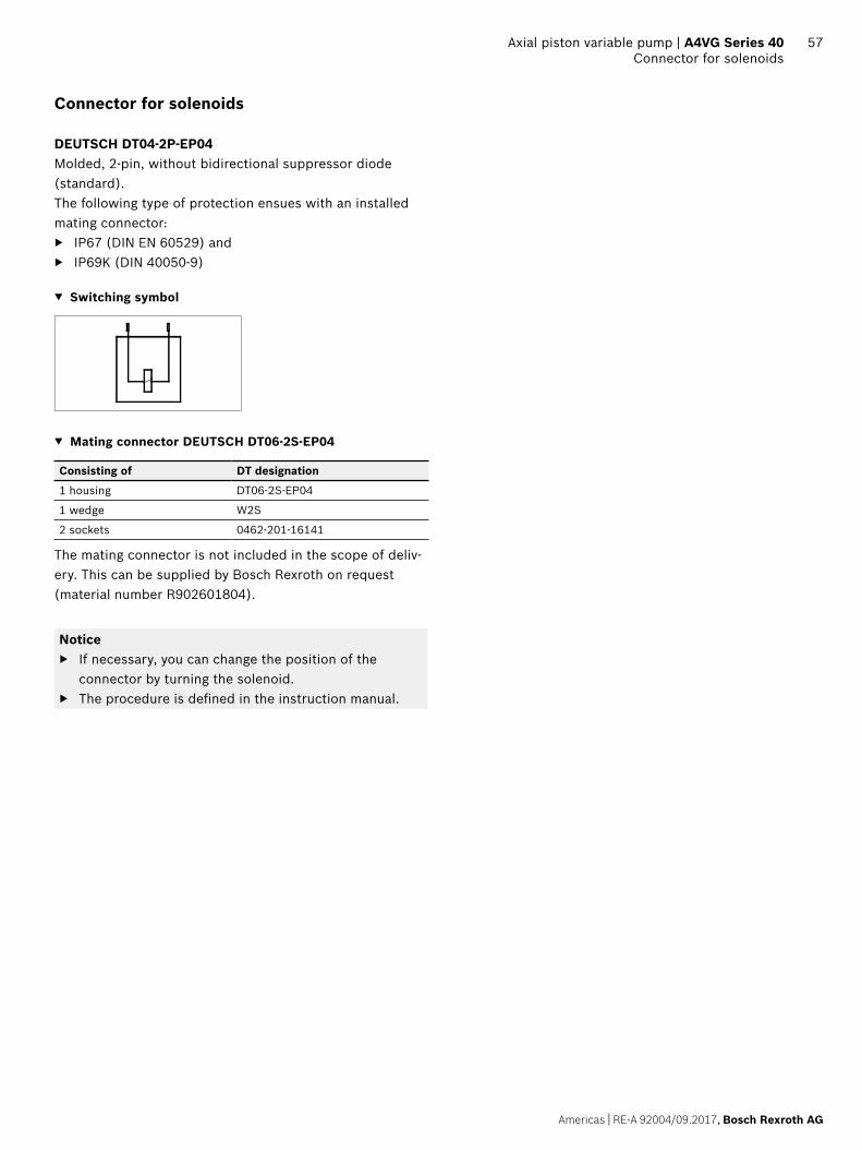
Americas | RE-A 92004/09.2017, Bosch Rexroth AG
Axial piston variable pump | A4VG Series 40 Connector for solenoids
57
Connector for solenoids
DEUTSCH DT04-2P-EP04Molded, 2-pin, without bidirectional suppressor diode (standard).The following type of protection ensues with an installed mating connector:
▶ IP67 (DIN EN 60529) and ▶ IP69K (DIN 40050-9)
▼ Switching symbol
▼ Mating connector DEUTSCH DT06-2S-EP04
Consisting of DT designation
1 housing DT06-2S-EP04
1 wedge W2S
2 sockets 0462-201-16141
The mating connector is not included in the scope of deliv-ery. This can be supplied by Bosch Rexroth on request (material number R902601804).
Notice ▶ If necessary, you can change the position of the
connector by turning the solenoid. ▶ The procedure is defined in the instruction manual.

58 A4VG Series 40 | Axial piston variable pumpSpeed sensor
Bosch Rexroth AG, RE-A 92004/09.2017
Dimensions [inch (mm)]
Speed sensor
With the speed sensor DSA/DSM mounted, a signal propor-tional to pump speed can be generated. The DSA/DSM sensor measures the speed and direction of rotation. Type code, technical data, dimensions and details on the con-nector, plus safety instructions about the sensor can be found in the relevant data sheet 95133 – DSA or 95132 – DSM. The sensor is mounted on the port provided for this purpose with a mounting bolt.
Dimensions
A1
A2
NG 110 125 145 175 210 280
A1 6.36 6.36 7.13 7.91 7.48 8.30
161.5 161.5 181.2 201.0 190 210.9
A2 0.22 0.22 0.22 0.22 0.22 0.22
5.5 5.5 5.5 5.5 5.5 5.5
Number of teeth
2.09 On request
2.28 2.40 2.52 2.80
53 58 61 64 71
NoticeIt is not possible to retrofit existing units with a speed sensor.
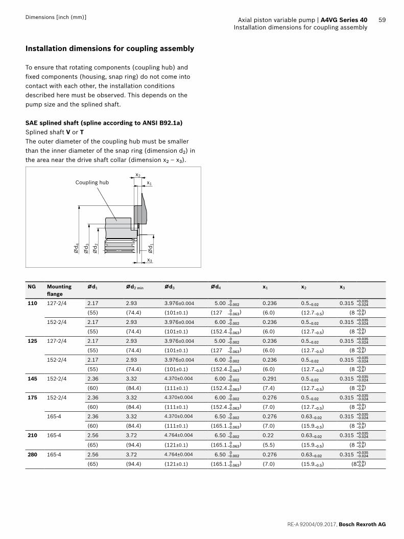
59
RE-A 92004/09.2017, Bosch Rexroth AG
Axial piston variable pump | A4VG Series 40 Installation dimensions for coupling assembly
Dimensions [inch (mm)]
Installation dimensions for coupling assembly
To ensure that rotating components (coupling hub) and fixed components (housing, snap ring) do not come into contact with each other, the installation conditions described here must be observed. This depends on the pump size and the splined shaft.
SAE splined shaft (spline according to ANSI B92.1a)Splined shaft V or TThe outer diameter of the coupling hub must be smaller than the inner diameter of the snap ring (dimension d2) in the area near the drive shaft collar (dimension x2 – x3).
⌀d 4
⌀d 3
⌀d 2
⌀d 1
x2
x1
x3
Coupling hub
NG Mounting flange
⌀d1 ⌀d2 min ⌀d3 ⌀d4 x1 x2 x3
110 127-2/4 2.17 2.93 3.976±0.004 5.00 0−0.002 0.236 0.5–0.02 0.315 +0.035
−0.024
(55) (74.4) (101±0.1) (127 0 )−0.063 (6.0) (12.7–0.5) (8 +0.9)−0.6
152-2/4 2.17 2.93 3.976±0.004 6.00 0−0.002 0.236 0.5–0.02 0.315 +0.035
−0.024
(55) (74.4) (101±0.1) (152.4 0 )−0.063 (6.0) (12.7–0.5) (8 +0.9)−0.6
125 127-2/4 2.17 2.93 3.976±0.004 5.00 0−0.002 0.236 0.5–0.02 0.315 +0.035
−0.024
(55) (74.4) (101±0.1) (127 0 )−0.063 (6.0) (12.7–0.5) (8 +0.9)−0.6
152-2/4 2.17 2.93 3.976±0.004 6.00 0−0.002 0.236 0.5–0.02 0.315 +0.035
−0.024
(55) (74.4) (101±0.1) (152.4 0 )−0.063 (6.0) (12.7–0.5) (8 +0.9)−0.6
145 152-2/4 2.36 3.32 4.370±0.004 6.00 0−0.002 0.291 0.5–0.02 0.315 +0.035
−0.024
(60) (84.4) (111±0.1) (152.4 0 )−0.063 (7.4) (12.7–0.5) (8 +0.9)−0.6
175 152-2/4 2.36 3.32 4.370±0.004 6.00 0−0.002 0.276 0.5–0.02 0.315 +0.035
−0.024
(60) (84.4) (111±0.1) (152.4 0 )−0.063 (7.0) (12.7–0.5) (8 +0.9)−0.6
165-4 2.36 3.32 4.370±0.004 6.50 0−0.002 0.276 0.63–0.02 0.315 +0.035
−0.024
(60) (84.4) (111±0.1) (165.1 0 )−0.063 (7.0) (15.9–0.5) (8 +0.9)−0.6
210 165-4 2.56 3.72 4.764±0.004 6.50 0−0.002 0.22 0.63–0.02 0.315 +0.035
−0.024
(65) (94.4) (121±0.1) (165.1 0 )−0.063 (5.5) (15.9–0.5) (8 +0.9)−0.6
280 165-4 2.56 3.72 4.764±0.004 6.50 0−0.002 0.276 0.63–0.02 0.315 +0.035
−0.024
(65) (94.4) (121±0.1) (165.1 0 )−0.063 (7.0) (15.9–0.5) (8+0.9)−0.6

60 A4VG Series 40 | Axial piston variable pumpInstallation instructions
Bosch Rexroth AG, RE-A 92004/09.2017
Dimensions [inch (mm)]
Installation instructions
GeneralThe axial piston unit must be filled with hydraulic fluid and air bled during commissioning and operation. This must also be observed following a longer standstill as the axial piston unit may empty via the hydraulic lines. Particularly in the installation position “drive shaft upwards”, filling and air bleeding must be carried out com-pletely as there is, for example, a danger of dry running.The leakage in the housing area must be directed to the reservoir via the highest drain port (T1, T2).For combination pumps, the leakage must be drained off at each pump. If a shared drain line is used for several units, make sure that the respective case pressure is not exceeded. The shared drain line must be dimensioned to ensure that the maximum permissible case pressure of all connected units is not exceeded in any operating conditions, specifically on cold start. If this is not possible, separate drain lines must be laid if necessary.To achieve favorable noise values, decouple all connecting lines using elastic elements and avoid above-reservoir installation. Under all operating conditions, the suction line and drain line must flow into the reservoir below the minimum fluid level. The permissible suction height hS results from the overall loss of pressure. However, it must not be higher than hS max = 31.5 in (800 mm). The suction pressure at port S must also not fall below the minimum value of 12 psi (0.8 bar) absolute during opera-tion (cold start 7.5 psi (0.5 bar) absolute).
Installation positionSee the following examples 1 to 12. Further installation positions are available upon request.Recommended installation position: 1 and 2.
Notice ▶ If filling the stroking chambers via X1 to X4 is not
possible in the final installation position, then this must take place before installation, e.g. in installation position 2.
▶ To prevent unexpected actuation and damage, the stroking chambers must be air bled via the ports X1, X2, or X3, X4 depending on the installation position.
▶ In certain installation positions, an influence on the control or closed loop control can be expected. Grav-ity, dead weight and case pressure can cause minor shifts in control characteristic curves and changes in response time.
Below-reservoir installation (standard)Below-reservoir installation means that the axial piston unit is installed outside of the reservoir and below the minimum fluid level of the reservoir.
Installation position
Air bleeding the housing
Air bleeding the stroking chamber
Filling
1 R X1, X2 S + T1 + X1 + X2
T1
X2, X1
S
R
SB
ht min
hmin
2 − − S + T2
SB
ht min
hmin
T2S

Americas | RE-A 92004/09.2017, Bosch Rexroth AG
Axial piston variable pump | A4VG Series 40 Installation instructions
61
Installation position
Air bleeding the housing
Air bleeding the stroking chamber
Filling
3 − X1, X2 S + T2 + X1 + X2
T2
SX2, X1
ht min
hmin
SB
4 R1 X3, X4 S + T1 + X3 + X4
ht min
hmin
SB
T1
S
R1
X4, X3
5 − X3 S + T2 + X3
ht min
hmin
X3T2
T1
S
SB
6 − X4 S + T1 + X4
ht min
hmin
X4
T2
T1
S
SB
Above-reservoir installationAbove-reservoir installation means that the axial piston unit is installed above the minimum fluid level of the reservoir.Observe the maximum permissible suction height hS max = 31.5 in (800 mm).Recommendation for installation position 10 (drive shaft upward): A check valve in the drain line (cracking pressure 7.5 psi (0.5 bar)) can prevent the housing area from drain-ing.
Installation position
Air bleeding the housing
Air bleeding the stroking chamber
Filling
7 F2 + R X1, X2 F1 + F2 + X1 + X2
ht min
hmin
T1
F2
S
R
SBhS max
F1 X2, X1
8 F2 (S) + F1 (T2) − F2 (S) + F1 (T2)
ht min
hmin
hS max
T2SF2
SB
F1
9 F2 (S) + F1 (T2) X1, X2 F2 (S) + F1 (T2) + X1 + X2
ht min
hmin
hS maxT2
SF2
SB
F1
X2, X1

Bosch Rexroth AG, RE-A 92004/09.2017 | Americas
62 A4VG Series 40 | Axial piston variable pumpInstallation instructions
Installation position
Air bleeding the housing
Air bleeding the stroking chamber
Filling
10 F2 + R1 X3, X4 F1 + F2 + X3 + X4
ht min
hmin
hS max
T1
S
F2
SB
7.5
psi
(0.5
bar
)F1
R1
X4, X3
11 F2 (S) + F1 (T2) X3 F2 (S) + F1 (T2) + X3
ht min
hmin
hS max
X3T2
T1
SF2
SB
F1
12 F2 (S) + F1 (T1) X4 F2 (S) + F1 (T1) + X4
ht min
hmin
hS max
X4
T2
T1
S
SB
F2
F1
Key
F1, F2 Filling / air bleeding
R Air bleed port
R1 Air bleed port (special version)
S Suction port
T1, T2 Drain port
X1, X2 Control pressure port
X3, X4 Stroking chamber pressure port
SB Baffle (baffle plate)
ht min Minimum required immersion depth 7.87 in (200 mm)
hmin Minimum required distance to reservoir bottom 3.94 in (100 mm)
hS max Maximum permissible suction height 31.5 in (800 mm)
NoticePorts F1 and F2 are part of the external piping and must be provided on the customer side to make filling and air bleeding easier.

Americas | RE-A 92004/09.2017, Bosch Rexroth AG
Axial piston variable pump | A4VG Series 40 Project planning notes
63
Project planning notes
▶ The pump A4VG is designed to be used in closed circuit. ▶ The project planning, installation and commissioning of
the axial piston unit requires the involvement of quali-fied skilled personnel.
▶ Before using the axial piston unit, please read the corresponding instruction manual completely and thoroughly. If necessary, these can be requested from Bosch Rexroth.
▶ Before finalizing your design, please request a binding installation drawing.
▶ The specified data and notes contained herein must be observed.
▶ Depending on the operating conditions of the axial piston unit (working pressure, fluid temperature), the characteristic curve may shift.
▶ Preservation: Our axial piston units are supplied as standard with preservative protection for a maximum of 12 months. If longer preservative protection is required (maximum 24 months), please specify this in plain text when placing your order. The preservation periods apply under optimal storage conditions, details of which can be found in the data sheet 90312 or the instruction manual.
▶ Not all versions of the product are approved for use in a safety function according to ISO 13849. Please consult the responsible contact person at Bosch Rexroth if you require reliability parameters (e.g. MTTFD) for functional safety.
▶ Depending on the type of control used, electromagnetic effects can be produced when using solenoids. Applying the recommended direct voltage signal (DC) to sole-noids does not create electromagnetic interference (EMI) nor is the solenoid affected by EMI. Electromag-netic interference (EMI) potential exists when operating and controlling a solenoid with a modulated direct voltage signal (e.g. PWM signal). Appropriate testing and measures should be taken by the machine manufacturer to ensure other components or operators (e.g. with pacemaker) are not affected by this potential.
▶ The pressure cut-off is not a safeguard against pressure overload. Be sure to add a pressure relief valve to the hydraulic system.
▶ With dynamic power flow (switch of pumps to operation as a motor) a maximum of 95% Vg max is permissible. We recommend configuring the software accordingly.
▶ For drives that are operated for a long period with con-stant rotational speed, the natural frequency of the hydraulic system can be excited by the excitation fre-quency of the pump (rotational speed frequency ×9). This can be prevented with suitably designed hydraulic lines.
▶ Please note the details regarding the tightening torques of port threads and other threaded joints in the instruc-tion manual.
▶ Working ports: – The ports and fastening threads are designed for the
specified maximum pressure. The machine or system manufacturer must ensure that the connecting ele-ments and lines correspond to the specified applica-tion conditions (pressure, flow, hydraulic fluid, tem-perature) with the necessary safety factors.
– The working ports and function ports are only intended to accommodate hydraulic lines.

64
Bosch Rexroth AG, RE-A 92004/09.2017 | Americas
Bosch Rexroth Corporation8 Southchase CourtFountain Inn, SC 29644-9018, USATelephone (864) 967-2777Facsimile (864) 967-8900www.boschrexroth-us.com
© Bosch Rexroth AG 2017. All rights reserved, also regarding any disposal, exploitation, reproduction, editing, distribution, as well as in the event of applications for industrial property rights. The data specified within only serves to describe the product. No statements concerning a certain condition or suitability for a certain application can be derived from our information. The information given does not release the user from the obligation of own judgment and verification. It must be remembered that our products are subject to a natural process of wear and aging.
A4VG Series 40 | Axial piston variable pumpSafety instructions
Safety instructions
▶ During and shortly after operation, there is a risk of getting burnt on the axial piston unit and especially on the solenoids. Take appropriate safety measures (e.g. by wearing protective clothing).
▶ Moving parts in control equipment (e.g. valve spools) can, under certain circumstances get stuck in position as a result of contamination (e.g. impure hydraulic fluid, abrasion, or residual dirt from components). As a result, the hydraulic fluid flow and the build-up of torque in the axial piston unit can no longer respond correctly to the operator's specifications. Even the use of various filter elements (external or internal flow filtration) will not rule out a fault but merely reduce the risk. The machine/system manufacturer must test whether remedial mea-sures are needed on the machine for the application concerned in order to set the consumer being driven to a safe position (e.g. safe stop) and if necessary to ensure it is properly implemented.
▶ Moving parts in high-pressure relief valves may in certain circumstances become stuck in an undefined position due to contamination (e.g. impure hydraulic fluid). This can result in restriction or loss of the load holding func-tion in lifting winches. The machine/system manufacturer must check whether additional measures are required on the machine for the relevant application in order to keep the load in a safe position and ensure they are properly implemented.