axial piston pump series pv - unitec parker · 2 parker hannifin gmbh ... pv046 46 69 45 pv063 63...
TRANSCRIPT

Catalogue HY11-3243/UKSeptember 2004
Axial Piston PumpSeries PVVariable Displacement

Axial Piston PumpSeries PV
Catalogue HY11-3243/UK
PI PVplus UK.PMD RH
2 Parker Hannifin GmbHHydraulic Controls DivisionKaarst, Germany
NoteThis document and other information from Parker HannifinGmbH, its subsidiaries, sales offices and authorizeddistributors provide product or system options for furtherinvestigation by users having technical expertise. Before youselect or use any product or system it is important that youanalyse all aspects of your application and review theinformation concerning the product or system in the currentproduct catalogue. Due to the variety of operating conditionsand applications for these products or systems, the user,through his own analysis and testing, is solely responsiblefor making the final selection of the products and systemsand assuring that all performance and safety requirementsof the application are met. The products are subject tochange by Parker Hannifin GmbH at any time without notice.

Axial Piston PumpSeries PV
Catalogue HY11-3243/UK
PI PVplus UK.PMD RH
3 Parker Hannifin GmbHHydraulic Controls DivisionKaarst, Germany
Introduction 4
Characteristics 5
Ordering code 6
Noise levels 8
Noise reduction measures 9
Efficiency and case drain flows 10
Dimensions 14
Mounting-, repair- and seal kits 24
Pump combinations
Dimensions 26
Thru drive, shaft load limitations 28
Compensators
Dimensions / Seal kit compensators 29
Pressure compensators 30
Load-Sensing compensators 31
Horse power compensators 32
Electrohydraulic p/Q control 34
Electrohydraulic p/Q control FP* / UP* 35
Electronic Module (analogue) 38
Electronic Module (digital) 39
Pump accessories PVAP* 40
Hydraulic circuit, ordering examples PVAC* 44
Proportional control valve 46
Safety manifolds PVAPS* 47
Accessories 52
General installation information 53
Table of contents
Description Page
Axial Piston PumpSeries PV
Catalogue HY11-3243/UK
PI PVplus UK.PMD RH
4 Parker Hannifin GmbHHydraulic Controls DivisionKaarst, Germany
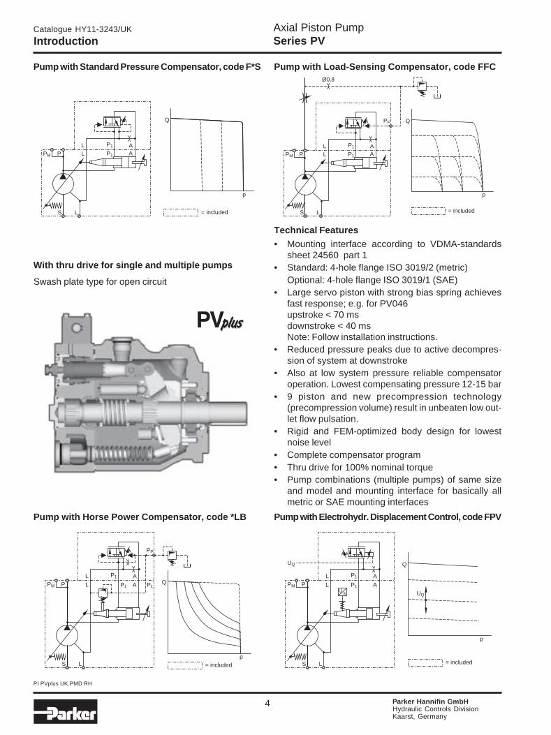
Introduction
Pump with Standard Pressure Compensator, code F*S Pump with Load-Sensing Compensator, code FFC
Pump with Horse Power Compensator, code *LB Pump with Electrohydr. Displacement Control, code FPV
With thru drive for single and multiple pumps
Swash plate type for open circuit
p
Q
P L
S L
AP1PM
L AP1
= included
p
Q
P L
S L
AP1PM
L AP1
PF
Ø0,8
= included
p
QP L
S L
AP1 PLPM
L AP1
PP
= included
P L
S L
AP1PM
sU
L AP1
UQ
p
Q
UQ
= included
Technical Features
• Mounting interface according to VDMA-standardssheet 24560 part 1
• Standard: 4-hole flange ISO 3019/2 (metric)Optional: 4-hole flange ISO 3019/1 (SAE)
• Large servo piston with strong bias spring achievesfast response; e.g. for PV046upstroke < 70 msdownstroke < 40 msNote: Follow installation instructions.
• Reduced pressure peaks due to active decompres-sion of system at downstroke
• Also at low system pressure reliable compensatoroperation. Lowest compensating pressure 12-15 bar
• 9 piston and new precompression technology(precompression volume) result in unbeaten low out-let flow pulsation.
• Rigid and FEM-optimized body design for lowestnoise level
• Complete compensator program• Thru drive for 100% nominal torque• Pump combinations (multiple pumps) of same size
and model and mounting interface for basically allmetric or SAE mounting interfaces

Axial Piston PumpSeries PV
Catalogue HY11-3243/UK
PI PVplus UK.PMD RH
5 Parker Hannifin GmbHHydraulic Controls DivisionKaarst, Germany
Characteristics
Displacement [cm3/rev] from 16 to 270
Operating pressures
Outlet [bar] nominal pressure pN 350
[bar] max. pressure pmax. 420 1)
[bar] drain port 2 2)
Inlet min. [bar] 0.8 (absolute)
max. [bar] 16
Minimum speed [min-1] 300 min-1
Mounting interface 4-hole flange ISO 3019/2
optional ISO 3019/1, SAE
Installation drain port as high as possible
Pump combinationsSee pages 26–27
Pump with Standard Pressure Comp. Pump with Horse Power Comp.
Combination PV/PV Combination PV/PGP
Selection table
Model Max. displacement Output flow Input horse power at Max speed * Moment of Weight [cm3/rev] at 1500 min-1 [l/min] 1500 min-1 and 350 bar [kW] [min-1] inertia [kgm²] [kg]
* The maximum speed ratings are shown for an inlet pressure of 1 bar (absolute) and for a fluid viscosity of ν = 30 mm²/s.
Technical data
1) max. 20% of working cycle2) peak pressure only, special version up to 20 bar available
(with X-Modification X5877)
PV016 16 24 15.5
PV020 20 30 19.5 3000 0.0017 19
PV023 23 34.5 22.5
PV032 32 48 31
PV040 40 60 39 2800 0.0043 30
PV046 46 69 45
PV063 63 94.5 61.5 2800
PV080 80 120 78 2500 0.018 60
PV092 92 138 89.5 2300
PV140 140 210 136 2400
PV180 180 270 175 22000.030 90
PV270 270 405 263 1800 0.098 172
Axial Piston PumpSeries PV
Catalogue HY11-3243/UK
PI PVplus UK.PMD RH
6 Parker Hannifin GmbHHydraulic Controls DivisionKaarst, Germany
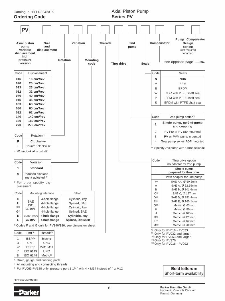
Ordering Code
Code 2nd pump option7)
1 Single pump, no 2nd pumpand coupling
2 PV140 or PV180 mounted
3 PV or PVM pump mounted
4 Gear pump series PGP mounted
Code Variation
1 Standard
9 Reduced displace-ment adjusted 2)
Code Displacement
016 16 cm³/rev020 20 cm³/rev023 23 cm³/rev032 32 cm³/rev040 40 cm³/rev046 46 cm³/rev063 63 cm³/rev080 80 cm³/rev092 92 cm³/rev140 140 cm³/rev180 180 cm³/rev270 270 cm³/rev
PV
Code Rotation 1)
R Clockwise
L Counter clockwise1) When looked on shaft
7) Specify 2nd pump with full model code
8) Only for PV016 - PV0239) Only for PV032 and larger10) Only for PV063 and larger11) Only for PV27012) Only for PV016 - PV092
2) For order specify dis-placement.
Code Port 4) Threads5)
1 BSPP Metric3 UNF UNC46) BSPP Metr. M147 ISO 6149 UNC8 ISO 6149 Metric1)
Code Mounting interface Shaft
D 4-hole flange Cylindric, keyE 4-hole flange Splined, SAEF3) 4-hole flange Cylindric, keyG3) 4-hole flange Splined, SAEK 4-hole flange Cylindric, keyL 4-hole flange Splined, DIN 5480
SAEISO
3019/1
metr. ISO3019/2
3) Codes F and G only for PV140/180, see dimension sheet
Code Thru drive optionno adaptor for 2nd pump
TSingle pump
prepared for thru drive
With adaptor for 2nd pump
Y8) SAE AA, Ø 50.8mmA SAE A, Ø 82.55mmB SAE B, Ø 101.6mm
C9) SAE C, Ø 127mmD10) SAE D, Ø 152.4mmE11) SAE E, Ø 165.1mmG12) Metric, Ø 63mmH Metric, Ø 80mmJ Metric, Ø 100mm
K9) Metric, Ø 125mmL10) Metric, Ø 160mmM11) Metric, Ø 200mm
Seals
Axial pistonpump
variabledisplacement
highpressureversion
Sizeand
displacement
2ndpump
Compensator
see opposite page
Variation Threads Designseries:
Mountingcode Thru drive
Rotation
4) Drain, gauge and flushing ports5) All mounting and connecting threads6) For PV063-PV180 only: pressure port 1 1/4" with 4 x M14 instead of 4 x M12
Code Seals
N NBR
V FPM
E EPDM
W NBR with PTFE shaft seal
P FPM with PTFE shaft seal
S EPDM with PTFE shaft seal
CompensatorPump
(not requiredfor order)
Axial Piston PumpSeries PV
Catalogue HY11-3243/UK
PI PVplus UK.PMD RH
7 Parker Hannifin GmbHHydraulic Controls DivisionKaarst, Germany
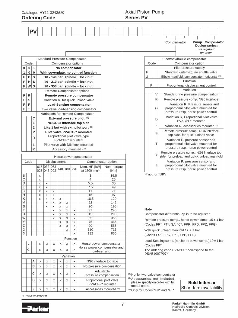
Function
L x x x x x x Horse power compensator
C x x x x x xHorse power compensator and
load-sensing
Variation
A x x x x x x NG6 interface top side
B x x x x x x No pressure compensation
C x x x x x xAdjustable
pressure compensation
D x x x x x x Proportional pilot valvePVACPP* mounted
Z x x x x x x Accessories mounted 14)
13) Not for two-valve-compensator14) Accessories not included,
please specify on order with fullmodel code.
15) Only for Codes *FR* and *FT*
PV
CompensatorPumpCompensator
Horse power compensator
Code Displacement Compensator option
016 032 063140 180 270
Nom. HP [kW] Nom. torque023 046 092 at 1500 min-1 [Nm]
B x 3 19.5C x 4 26D x x 5.5 36E x x 7.5 49G x x x 11 71H x x x 15 97K x x x x 18.5 120M x x x x 22 142S x x x x 30 195T x x x x 37 240U x x x x 45 290W x x x x 55 355Y x x x 75 485Z x x x 90 5852 x x 110 7153 x 132 850
Standard Pressure CompensatorCode Compensator options
0 0 1 No compensator1 0 0 With coverplate, no control functionF D S 10 - 140 bar, spindle + lock nutF H S 40 - 210 bar, spindle + lock nutF W S 70 - 350 bar, spindle + lock nut
Remote Compensator optionsF R Remote pressure compensatorF S Variation R, for quick unload valveF F Load-Sensing compensatorF T Two valve load-sensing compensator
Variations for Remote CompensatorC External pressure pilot 13)
1 NG6/D03 interface top side2 Like 1 but with ext. pilot port 15)
P Pilot valve PVAC1P* mounted
D Proportional pilot valve typePVACPP* mounted
L Pilot valve with DIN lock mountedZ Accessory mounted 14)
Ordering Code
Design series:not required
for order
16) not for *UPV
NoteCompensator differential ∆p is to be adjusted:
Remote pressure comp., horse power comp. 15 ± 1 bar
(Codes FR*, FT*, *L*, *C*, FPR, FPD, FPZ, FPG)
With quick unload manifold 12 ± 1 bar
(Codes FS*, FPS, FPT, FPP, FPE)
Load-Sensing comp. (not horse power comp.) 10 ± 1 bar
(Codes FF*)
The ordering code PVACPP* correspond to theDSAE1007P07*
Electrohydraulic compensator Code Compensator option
Pilot pressure supplyF Standard (internal), no shuttle valveU Elbow manifold, compensator horizontal 16)
FunctionP Proportional displacement control
VariationV Standard, no pressure compensation
R Remote pressure comp. NG6 interface
Variation R, Pressure sensor andG proportional pilot valve mounted for
pressure resp. horse power control
D Variation R, Proportional pilot valve
PVACPP* mounted
Z Variation R, accessories mounted 14)
SRemote pressure comp., NG6 interface
top side, for quick unload valve
Variation S, pressure sensor andT proportional pilot valve mounted for
pressure resp. horse power control
Remote pressure comp., NG6 interface topP side, for preload and quick unload manifold
Variation P, pressure sensor andE proportional pilot valve mounted for
pressure resp. horse power control

Axial Piston PumpSeries PV
Catalogue HY11-3243/UK
PI PVplus UK.PMD RH
8 Parker Hannifin GmbHHydraulic Controls DivisionKaarst, Germany
Noise Levels
PV016 - PV023 PV140
PV032 - PV046 PV180
PV063 - PV092 PV270
Typical sound level for single pumps, measured in unechoic chamberaccording to DIN 45 635, part 1 and 26. Microphone distance 1m;speed: n = 1500 min-1.
All data measured with mineral oil viscosity 30 mm²/s (cSt) at 50°C.

Axial Piston PumpSeries PV
Catalogue HY11-3243/UK
PI PVplus UK.PMD RH
9 Parker Hannifin GmbHHydraulic Controls DivisionKaarst, Germany
Operating noise of pumps
The normal operating noise of a pump and consequentlythe operating noise of the entire hydraulic system arelargely determined by where and how the pump ismounted and how it is connected to the downstreamhydraulic system.
Also size, style and installation of the hydraulic tubinghave a major influence on the overall noise emitted by ahydraulic system.
Noise reduction measures
Talking about operating noise of a hydraulic pump,primary and secondary pump noise has to be taken intoconsideration.
Primary pump noise is caused by vibrations of thepump body due to internal alternating forces stressingthe body structure.
Flexible elements help to prevent pump body vibrationbeing transmitted to other construction elements, wherepossible amplification may occur. Such elements can be:
• Bell housing with elastic dampening flange withvulcanized labyrinth (1)
• Floating and flexible coupling (2)
• Damping rails (3) or silent blocks for mounting theelectric motor or the foot mounting flange
• Flexible tube connections (compensators) or hoseson inlet, outlet and drain port of the pump
• Exclusive use of gas tight tube fittings for inletconnections to avoid ingression of air causing cavitationand excessive noise
9.0 9.5 10.0 10.5 11.0 11.5[s]180
180
160
200
200
220[bar]
serie
s 20
serie
s 40
[bar]
PV180R1K1T1NFWS-series 40
PV180R1K1T1NFWS-series 20Secondary pump noise is caused by vibration inducedinto all connected hydraulic components by the flow andpressure pulsation of the pump. This secondary noiseadds typical 7 - 10 dB(A) to the noise of a pump measuredin the sound chamber according to DIN 45 635 (seediagrams on opposite side). Therefore pipework, itsmounting and the mounting of all hydraulic componentslike pressure filters and control elements have a majorinfluence on the overall system noise level.
Pulsation reduction with precompression volume
The PV is equipped with a new technology for flow ripplereduction. This method reduces the pulsation at the pumpoutlet by 40 - 60 %. That leads to a significant reductionof the overall system noise without additional cost andwithout additional components (silencers etc.). The typicalreduction reaches 2 - 4 dB(A). That means: with a pumpof the PV series the secondary noise adds only some 5- 7 dB(A) to the pump noise instead of 7 - 10 dB(A) asusually found.
Figure 2 compares the measured pulsation of a systemwith 6 pumps of 180 cm³/rev each.
1) Bell housing 2) Coupling 3) Damping rails
Last but not least the connection between pump anddriving motor can be the cause of an unacceptably highnoise emission. Even when the mounting space is limitedthere are suitable means and components to reduce thenoise significantly.The vibration of the pump body, created by high alternat-ing forces in the rotating group and the pulsation of theoutput flow excite every part of the system connected tothe pump mechanically or hydraulically.
Other measures
Small diameter tubes do not only cause high flow speeds,turbulences inside the tubes and cavitation in the pump,they also produce noise.
Only correctly sized connections of the largest possiblediameter according to the port size of the pump should beused.
Figure 1: Components to avoid vibration transfer from the pump tothe drive/installation and their position in the power unit (numbersrefer to the text on the left)
Figure 2: Comparison of the pressure pulsation in a system with 6old PV pumps versus the same system with 6 PVplus pumps. Thepulsation reduction effect of the precompression volume is evident.
Noise Reduction Measures

Axial Piston PumpSeries PV
Catalogue HY11-3243/UK
PI PVplus UK.PMD RH
10 Parker Hannifin GmbHHydraulic Controls DivisionKaarst, Germany
4
0
8
12
16
20
0 100 200 3000
20
40
60
80
100
0
5
10
15
20
25
Pressure [bar]
Effi
cien
cy [%
] (ov
eral
l, vo
lum
etr ic
)
Inpu
t pow
er [k
W]
Out
put f
low
[l/m
in]
vol. efficiency
overall e ncff eici y
output flow
input power at full flow
input power at deadhead
PV020
5
0
10
15
20
25
0 100 200 3000
20
40
60
80
100
0
6
12
18
24
30
Pressure [bar]
Effi
cien
cy [%
] (ov
eral
l, vo
lum
etr ic
)
Inpu
t pow
er [k
W]
Out
put f
low
[l/m
in]
overall nefficie cy
output flow, vol. efficiency
input power at full flow
input power at deadhead
PV023
5
0
10
15
20
25
0 100 200 3000
20
40
60
80
100
0
8
16
24
32
40
Pressure [bar]
Effi
cien
cy [%
] (ov
eral
l, vo
lum
etr ic
)
Inpu
t pow
er [k
W]
Out
put f
low
[l/m
in]
vol. efficiency
o everall effici ncyoutput flow
input
power
atful
l flow
input power at deadhead
Efficiency and case drain flows PV016, PV020, PV023
The efficiency and power graphs are measured at aninput speed of n = 1500 min-1, a temperature of 50°C anda fluid viscosity of 30 mm2/s.
Case drain flow and compensator control flow leave viathe drain port of the pump. To the values shown are to beadded 1 to 1.2 l/min , if at pilot operated compensators(codes FR*, FF*, FT*, horse power compensator and p/Q-control) the control flow of the pressure pilot valve alsogoes through the pump.
Please note: The values shown below are only valid forstatic operation. Under dynamic conditions and at rapidcompensation of the pump the volume displaced by theservo piston also leaves the case drain port. This dy-namic control flow can reach up to 40 l/min! Therefore thecase drain line is to lead to the reservoir at full size andwithout restrictions as short and direct as possible.
Case drain flows PV016-023
Efficiency, power consumptionPV016
Efficiency and Case Drain Flows

Axial Piston PumpSeries PV
Catalogue HY11-3243/UK
PI PVplus UK.PMD RH
11 Parker Hannifin GmbHHydraulic Controls DivisionKaarst, Germany
Efficiency and case drain flows PV032, PV040, PV046
The efficiency and power graphs are measured at aninput speed of n = 1500 min-1, a temperature of 50°C anda fluid viscosity of 30 mm2/s.
Case drain flow and compensator control flow leave viathe drain port of the pump. To the values shown are to beadded 1 to 1.2 l/min , if at pilot operated compensators(codes FR*, FF*, FT*, horse power compensator and p-Q-control) the control flow of the pressure pilot valve alsogoes through the pump.
Please note: The values shown below are only valid forstatic operation. Under dynamic conditions and at rapidcompensation of the pump the volume displaced by theservo piston also leaves the case drain port. This dy-namic control flow can reach up to 60 l/min! Therefore thecase drain line is to lead to the reservoir at full size andwithout restrictions as short and direct as possible.
Case drain flows PV032-046
Efficiency, power consumptionPV032
Efficiency and Case Drain Flows
8
0
16
24
32
40
0 100 200 3000
20
40
60
80
100
0
10
20
30
40
50
over lal effici ncye
output flow
input power at full flow
input power at deadhead
vol. efficiency
Pressure [bar]E
ffici
ency
[%] (
over
all,
volu
met
r ic)
Inpu
t pow
er [k
W]
Out
put f
low
[l/m
in]
8
0
16
24
32
40
0 100 200 3000
20
40
60
80
100
0
12
24
36
48
60
overall efficiency
output flow, vol. efficiency
input power at full flow
input power at deadhead
Pressure [bar]
Effi
cien
cy [%
] (ov
eral
l, vo
lum
etr ic
)
Inpu
t pow
er [k
W]
Out
put f
low
[l/m
in]
10
0
20
30
40
50
0 100 200 3000
20
40
60
80
100
0
16
32
48
64
80 vol. efficiencyovera fficll e iency
output flow
input power at fu
ll flow
i unp t power at deadhead
Pressure [bar]
Effi
cien
cy [%
] (ov
eral
l, vo
lum
etr ic
)
Inpu
t pow
er [k
W]
Out
put f
low
[l/m
in]
PV040
PV046

Axial Piston PumpSeries PV
Catalogue HY11-3243/UK
PI PVplus UK.PMD RH
12 Parker Hannifin GmbHHydraulic Controls DivisionKaarst, Germany
Case drain flows PV063-092
Efficiency, power consumptionPV063
Efficiency and case drain flows PV063, PV080, PV092
The efficiency and power graphs are measured at aninput speed of n = 1500 min-1, a temperature of 50°C anda fluid viscosity of 30 mm2/s.
Case drain flow and compensator control flow leave viathe drain port of the pump. To the values shown are to beadded 1 to 1.2 l/min , if at pilot operated compensators(codes FR*, FF*, FT*, horse power compensator and p-Q-control) the control flow of the pressure pilot valve alsogoes through the pump.
Please note: The values shown below are only valid forstatic operation. Under dynamic conditions and at rapidcompensation of the pump the volume displaced by theservo piston also leaves the case drain port. This dy-namic control flow can reach up to 80 l/min! Therefore thecase drain line is to lead to the reservoir at full size andwithout restrictions as short and direct as possible.
14
0
28
42
56
70
0 100 200 3000
20
40
60
80
100
0
20
40
60
80
100
overall efficiency
output flow
input
power at
full fl
ow
input power at deadhead
vol. efficiency
Pressure [bar]
Effi
cien
cy [%
] (ov
eral
l, vo
lum
etric
)
Inpu
t pow
er [k
W]
Out
put f
low
[l/m
in]
16
0
32
48
64
80
0 100 200 3000
20
40
60
80
100
0
24
48
72
96
120
overal effl iciency
output flow, vol. efficiency
input
power
atfu
ll flow
input power at deadhead
Pressure [bar]
Effi
cien
cy [%
] (ov
eral
l, vo
lum
etr ic
)
Inpu
t pow
er [k
W]
Out
put f
low
[l/m
in]
20
0
40
60
80
100
0 100 200 3000
20
40
60
80
100
0
30
60
90
120
150
overa ll effic cien y
output flow
input
power
atful
l flow
vol. efficiency
input power at deadhead
Pressure [bar]
Effi
cien
cy [%
] (ov
eral
l, vo
lum
etr ic
)
Inpu
t pow
er [k
W]
Out
put f
low
[l/m
in]
PV080
PV092
Efficiency and Case Drain Flows

Axial Piston PumpSeries PV
Catalogue HY11-3243/UK
PI PVplus UK.PMD RH
13 Parker Hannifin GmbHHydraulic Controls DivisionKaarst, Germany
Efficiency and case drain flows PV140, PV180, PV270
The efficiency and power graphs are measured at aninput speed of n = 1500 min-1, a temperature of 50°C anda fluid viscosity of 30 mm2/s.
Case drain flow and compensator control flow leave viathe drain port of the pump. To the values shown are to beadded 1 to 1.2 l/min , if at pilot operated compensators(codes FR*, FF*, FT*, horse power compensator and p-Q-control) the control flow of the pressure pilot valve alsogoes through the pump.
Please note: The values shown below are only valid forstatic operation. Under dynamic conditions and at rapidcompensation of the pump the volume displaced by theservo piston also leaves the case drain port. This dy-namic control flow can reach up to 120 l/min! Thereforethe case drain line is to lead to the reservoir at full size andwithout restrictions as short and direct as possible.
Efficiency, power consumptionPV140
Case drain flows PV140-180
30
0
60
90
120
150
0 100 200 3000
20
40
60
80
100
0
50
100
150
200
250
overall efficien yc
output flow
input p
ower
atful
l flow
input power at deadhead
vol. efficiency
Pressure [bar]E
ffici
ency
[%] (
over
all,
volu
met
r ic)
Inpu
t pow
er [k
W]
Out
put f
low
[l/m
in]
35
0
70
105
140
175
0 100 200 3000
20
40
60
80
100
0
60
120
180
240
300
over
all e
ffici
ency
output flow
input
power
atfu
ll flow
vol. efficiency
input power at deadhead
Pressure [bar]
Effi
cien
cy [%
] (ov
eral
l, vo
lum
etr ic
)
Inpu
t pow
er [k
W]
Out
put f
low
[l/m
in]
50
0
100
150
200
250
0 100 200 3000
20
40
60
80
100
0
100
200
300
400
500 vol. efficiency
overall eff eici ncy
output flow
input
power
atfu
ll flow
input power at deadhead
Pressure [bar]
Effi
cien
cy [%
] (ov
eral
l, vo
lum
etr ic
)
Inpu
t pow
er [k
W]
Out
put f
low
[l/m
in]
PV180
PV270 Case drain flows PV270
Efficiency and Case Drain Flows

Axial Piston PumpSeries PV
Catalogue HY11-3243/UK
PI PVplus UK.PMD RH
14 Parker Hannifin GmbHHydraulic Controls DivisionKaarst, Germany
Dimensions
PV016 - 023, metric version
109
952
1332
197.5
max. 212
Ø 25k6
16.5
16.5
132max. 133
80
140
125
12
22
170.5162
89
28-0.2548
55
15
58.7
30.2
32
19
23.8
50.8
Ø 100h8
43
127
Ø 100h8
120
94
key 8 x 7 x 40DIN 6885
thread M10 - 22 deep
X
View X
flushing port L3; G 3/8optional M 18 x 1.5; ISO 6149-1(threads options 7 and 8)oder 3/4 - 16 UNF( 3)threads option
mounting option Lsplined shaft W 25 x 1.5 x 15 x 8f DIN 5480
The pump shown above hasand (prepared for thru drive).
mounting option Kthru drive option T
4 x M10, 18 deepoptional 3/8 - 16 UNC - 2B( 3 and 7)threads options
Outlet:flange according ISO 6162DN 19; PN 400 bar
4 x M10, 18 deepoptional 7/16 - 14 UNC - 2B( 3 and 7)threads options
Inlet:flange according ISO 6162DN 32; PN 250 bar
gage port M; G1/4optional M 12 x 1.5; ISO 6149-1( 7 and 8)oder 7/16 - 20 UNF( 3)
threads options
threads option
drain port L2; G1/2optional M 22 x 1.5; ISO 6149-1(threads options 7 and 8)or 7/8 - 14 UNF( 3)threads option
drain port L1,dimensions see L2
Shown with standard pressure compensator
mounting hole forhorse power compensator pilotor displacement feedback LVDT
Shown is a clockwise rotating pump. Counter clockwise rotating pumps have inlet, outlet and gauge ports reversed.For further information about flanges see catalogue No. 4039/UK „Pressure Hydraulic Flanges“ (on request).

Axial Piston PumpSeries PV
Catalogue HY11-3243/UK
PI PVplus UK.PMD RH
15 Parker Hannifin GmbHHydraulic Controls DivisionKaarst, Germany
Dimensions
PV016 - 023, SAE version and thru drive
Dimension H and available couplings see page 24.At threads options 3 and 7 the dimensions E and G are UNC - 2Bthreads.
Thru shaft adaptors are available with the following dimensions:
A B C D E F G
63 10 85 - M8 100 M880 10 103 - M8 109 M10
100 10.5 125 - M10 - -50.8 10 - - - 82 M8
82.55 10 - - - 106 M10101.6 10.5 - 89.8 M12 - -
Variation with thru drive
Ø 25.4-0.05
28.17±0.13
Ø 101.6-0.05
9.48
4250
44.989.8
89.8
44.9
46
Ø 101.6-0.05
thread3/8-16 UNC-2B22 deep
mounting option Esplined shaft 15T 16/32 DP, flat root, side fitANSI B92.1
Shown above is mounting option D
key6.35 x 6.3540 long
13.5
C
E
DF
GA
B
197.5225
47.5
H
drive output: splined shaft13T-16/32 DP, flat root, side fitANSI B92.1

Axial Piston PumpSeries PV
Catalogue HY11-3243/UK
PI PVplus UK.PMD RH
16 Parker Hannifin GmbHHydraulic Controls DivisionKaarst, Germany
Dimensions
PV032 - 046, metric version
9
10
153
107
92
156
max. 133
14
160
Ø 125 h8
47
27.8
57.225
3869.9
35.7
146
185
197
17
6066 35-0.25
98
X
968
Ø 32k6
Ø 125h8
150
22
22
227max. 245
1537
28
View X
flushing port L3; G 1/2optional M 22 x 1.5; ISO 6149-1(threads options 7 and 8)oder 7/8 - 14 UNF( 3)threads option
mounting option Lsplined shaft W 32 x 1.5 x 20 x 8f DIN 5480
The pump shown above hasand (prepared for thru drive)
mounting option Kthru drive option T
4 x M12, 18 deepoptional 7/16 - 14 UNC - 2B( 3 and 7)threads options
Outlet:flange according ISO 6162DN 25; PN 400 bar
4 x M12, 18 deepoptional 1/2 - 13 UNC - 2B( 3 and 7)threads options
Inlet:flange according ISO 6162DN 38; PN 200 bar
gage port M; G1/4optional M 12 x 1.5; ISO 6149-1( 7 and 8)oder 7/16 - 20 UNF( 3)
threads options
threads option
Key 10 x 8 x 56DIN 6885
Thread M10 - 22 deep
drain port L2; G3/4optional M 27 x 2; ISO 6149-1(threads options 7 and 8)or 1 1/16 - 12 UNF( 3)threads option
drain port L1,dimensions see L2
Shown with standard pressure compensator
mounting hole forhorse power compensator pilotor displacement feedback LVDT
Shown is a clockwise rotating pump. Counter clockwise rotating pumps have inlet, outlet and gauge ports reversed.For further information about flanges see catalogue No. 4039/UK „Pressure Hydraulic Flanges“ (on request).
Axial Piston PumpSeries PV
Catalogue HY11-3243/UK
PI PVplus UK.PMD RH
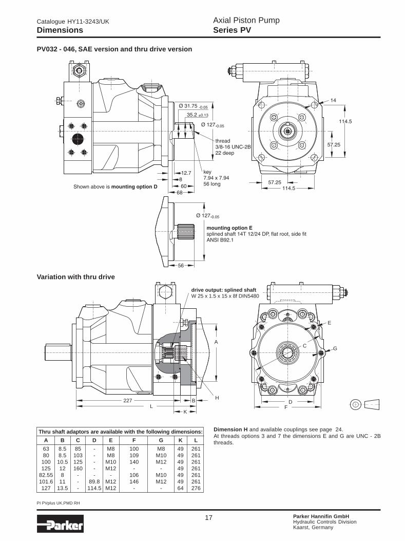
17 Parker Hannifin GmbHHydraulic Controls DivisionKaarst, Germany
Dimensions
PV032 - 046, SAE version and thru drive version
Dimension H and available couplings see page 24.At threads options 3 and 7 the dimensions E and G are UNC - 2Bthreads.
Thru shaft adaptors are available with the following dimensions:
A B C D E F G K L
63 8.5 85 - M8 100 M8 49 26180 8.5 103 - M8 109 M10 49 261
100 10.5 125 - M10 140 M12 49 261125 12 160 - M12 - - 49 261
82.55 8 - - - 106 M10 49 261101.6 11 - 89.8 M12 146 M12 49 261127 13.5 - 114.5 M12 - - 64 276
C
D
E
F
GA
B227L
K
H
drive output: splined shaftW 25 x 1.5 x 15 x 8f DIN5480
Variation with thru drive
Axial Piston PumpSeries PV
Catalogue HY11-3243/UK
PI PVplus UK.PMD RH
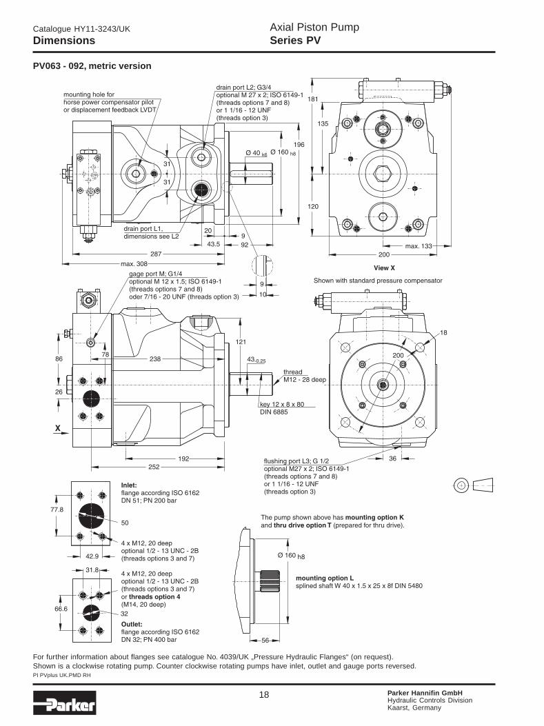
18 Parker Hannifin GmbHHydraulic Controls DivisionKaarst, Germany
Dimensions
PV063 - 092, metric version
Shown is a clockwise rotating pump. Counter clockwise rotating pumps have inlet, outlet and gauge ports reversed.For further information about flanges see catalogue No. 4039/UK „Pressure Hydraulic Flanges“ (on request).

Axial Piston PumpSeries PV
Catalogue HY11-3243/UK
PI PVplus UK.PMD RH
19 Parker Hannifin GmbHHydraulic Controls DivisionKaarst, Germany
Thru shaft adaptors are available with the following dimensions:
A B C D E F G K L
63 10 85 - M8 100 M8 58 32680 10 103 - M8 109 M10 58 326
100 12 125 - M10 140 M12 58 326125 12 160 - M12 180 M16 58 326160 12 200 - M16 - - 58 326
82.55 10 - - - 106 M10 58 326101.6 12 - 89.8 M12 146 M12 58 326127 14 - 114.5 M12 181 M16 58 326
152.4 14 - 161.6 M16 - - 78 346
287
C
D
E
F
G
A
BL
K
H
drive output: splined shaftW 32 x 1.5 x 20 x 8f DIN5480
Dimensions
PV063 - 092, SAE version and thru drive version
Dimension H and available couplings see page 24.At threads options 3 and 7 the dimensions E and G are UNC - 2Bthreads.
Variation with thru drive

Axial Piston PumpSeries PV
Catalogue HY11-3243/UK
PI PVplus UK.PMD RH
20 Parker Hannifin GmbHHydraulic Controls DivisionKaarst, Germany
Dimensions
910
204
158
145
200max. 133
View X
200
flushing port L3; G 3/4optional M 27 x 2; ISO 6149-1(threads options 7 and 8)oder 1 1/16 - 12 UNF( 3)threads option
Ø 160h8
78
mounting option Lsplined shaft W 50 x 2 x 24 x 9g DIN 5480
The pump shown above hasand
mounting option Kthru drive option T (prepared for thru drive).
31.8
66.6
4 x M12, 20 deepoptional 1/2 - 13 UNC - 2B( 3 and 7)orM14, 22 deep)
threads options
(threads option 4
32
Outlet:flange according ISO 6162DN 32; PN 400 bar
4 x M12, 20 deepoptional 1/2 - 13 UNC - 2B( 3 and 7)threads options
64
Inlet:flange according ISO 6162DN 64; PN 160 bar
88.9
50.8
gage port M; G1/4optional M 12 x 1.5; ISO 6149-1( 7 and 8)oder 7/16 - 20 UNF( 3)
threads options
threads option
283
233pressure port: 295suction port: 305
105106
53.5-0.25
147
Key 14 x 9 x 75DIN 6885
Thread M16 - 36 deep
X
992
Ø 50k6
Ø 160h8
200
35
35
350max. 385
48
drain port L2; G1optional M 33 x 2; ISO 6149-1(threads options 7 and 8)or 1 5/16 - 12 UNF( 3)threads option
drain port L1dimensions see L2
40
Shown with standard pressure compensator
mounting hole forhorse power compensatorpilot or LVDT fordisplacement feedback
20
18
PV140 - 180, metric version
Shown is a clockwise rotating pump. Counter clockwise rotating pumps have inlet, outlet and gauge ports reversed.For further information about flanges see catalogue No. 4039/UK „Pressure Hydraulic Flanges“ (on request).

Axial Piston PumpSeries PV
Catalogue HY11-3243/UK
PI PVplus UK.PMD RH
21 Parker Hannifin GmbHHydraulic Controls DivisionKaarst, Germany
Dimensions
Variation with thru drive
Thru shaft adaptors are available with the following dimensions:
A B C D E F G
80 10 103 - M8 109 M10100 12 125 - M10 140 M12125 12 160 - M12 180 M16160 12 200 - M16 - -
82.55 10 - - - 106 M10101.6 12 - 89.8 M12 146 M12127 14 - 114.5 M12 181 M16
152.4 14 - 161.6 M16 - -
350415
97
B
A
FD
C
E
G
drive output: splined shaftW 40 x 1.5 x 25 x 8f DIN5480
H
PV140 - 180, SAE version and thru drive version
Dimension H and available couplings see page 24.At threads options 3 and 7 the dimensions E and G are UNC - 2Bthreads.

Axial Piston PumpSeries PV
Catalogue HY11-3243/UK
PI PVplus UK.PMD RH
22 Parker Hannifin GmbHHydraulic Controls DivisionKaarst, Germany
PV 270, metric version
Dimensions
Shown is a clockwise rotating pump. Counter clockwise rotating pumps have inlet, outlet and gauge ports reversed.For further information about flanges see catalogue No. 4039/UK „Pressure Hydraulic Flanges“ (on request).

Axial Piston PumpSeries PV
Catalogue HY11-3243/UK
PI PVplus UK.PMD RH
23 Parker Hannifin GmbHHydraulic Controls DivisionKaarst, Germany
PV 270, SAE version and thru drive version
Dimension H and available couplings see page 24.At threads options 3 and 7 the dimensions E and G are UNC - 2Bthreads.
Thru shaft adaptors are available with the following dimensions:
A B C D E F G
80 8.5 103 - M8 109 M10100 10.5 125 - M10 140 M12125 10.5 160 - M12 180 M16160 13.5 200 - M16 224 M20200 13.5 250 - M20 - -
82.55 8 - - - 106 M10101.6 11 - 89.8 M12 146 M12127 13.5 - 114.5 M12 181 M16
152.4 13.5 - 161.6 M16 229 M20165.1 17 - 224.5 M20 - -
H
A
B
531.597
DF
E
G
C
output: splined shaftW 50 x 2 x 24 x 9g DIN 5480
472.5
Variation with thru drive
Dimensions

Axial Piston PumpSeries PV
Catalogue HY11-3243/UK
PI PVplus UK.PMD RH
24 Parker Hannifin GmbHHydraulic Controls DivisionKaarst, Germany
Code Second pump, SAE
T Prepared for thru drive option (plugged)Y SAE AA, diameter 50.8 mmA SAE A, diameter 82.55 mmB SAE B, diameter 101.6 mmC SAE C, diameter 127,mmD SAE D, diameter 152.4 mmE SAE E, diameter 165.1 mm
Second pump, metric
G Diameter 63 mmH Diameter 80 mmJ Diameter 100 mmK Diameter 125 mmL Diameter 160 mmM Diameter 200 mm
Designseries
(see nameplate)
SealsSecondpump
Thread
PVMK
Axialpistonpump
series PV
BG
Size
Code Seals
N NBRV FPME EPR
front pump second pump
metric,splined
keyed shaft,(only up to Ø 18,metric)
SAE,splined
30 84
69
91
85 87
92
Mountingkit
Code Thread
M MetricS SAE
PVMK
Axialpistonpump
series PV
BG
SizeMountingkit
Coupling
Mounting kits for multiple pumps, for second pump option
Mounting kits for multiple pumps, couplings
Kits
Code Pump size
1 Pump size 1: PV016 - PV0232 Pump size 2: PV032 - PV0463 Pump size 3: PV063 - PV0924 Pump size 4: PV140 - PV1805 Pump size 5: PV270
Kit contains positions 30, 69, 84,85 and 87, see drawing below.
Code Pump size
1 Pump size 1: PV016 - PV0232 Pump size 2: PV032 - PV0463 Pump size 3: PV063 - PV0924 Pump size 4: PV140 - PV1805 Pump size 5: PV270
Code Coupling for metric,splined shaft DIN 5480
01 N25 x 1.5 x 1502 N32 x 1.5 x 2003 N40 x 1.5 x 2504 N50 x 2 x 2405 N60 x 2 x 28
Coupling for SAE splined shaftflat root, side fit
11 9T 16/3212 11T 16/3213 13T 16/3214 15T 16/3215 14T 12/2416 17T 12/2417 13T 8/1618 15T 8/16
Coupling + adaptorfor keyed shaft
20 Diameter 12 mm21 Diameter 16 mm22 Diameter 18 mm
Kit contains positions 91 (and 92 forkeyed shaft).
Designseries
(see nameplate)
K

Axial Piston PumpSeries PV
Catalogue HY11-3243/UK
PI PVplus UK.PMD RH
25 Parker Hannifin GmbHHydraulic Controls DivisionKaarst, Germany
Code Seals
N NBRV FPME EPRW NBR with PTFE shaft sealP FPM with PTFE shaft sealS EPDM with PTFE shaft seal
Axialpistonpump
series PV
Seals
Code Thread Port
1 Metric BSPP3 UNC UNF7 UNC ISO 61498 Metric ISO 6149
Thread,port
Seal kit
Spareparts kit
PVSK BG
Size
PVRK BG
Axialpistonpump
series PV
Size Contents
Code
016 PV016020 PV020023 PV023032 PV032040 PV040046 PV046
Code Contents
HE Displacement limiteradjustable
063 PV063080 PV080092 PV092140 PV140180 PV180270 PV270
Displacement
Axialpistonpump
series PV
Spareparts kit
PVRK
Displace-ment
Contents Seals
Code Seals
N NBRV FPME EPR
Code Thread
M MetricS SAE / UNC
Rotation
R ClockwiseL Counter-clockw.
Seals
N NBRV FPME EPR
partlyoptional:Threador rotation or
seals
Seal kits
Repair and spare parts kits
Repair and spare parts kits for adjustable displacement limiter
Kits
Code Pump size
1 Pump size 1: PV016 - PV0232 Pump size 2: PV032 - PV0463 Pump size 3: PV063 - PV0924 Pump size 4: PV140 - PV1805 Pump size 5: PV270
Designseries
(see nameplate)
Designseries
(see nameplate)
Code Contents Optional
VT Connecting parts, kit ThreadWP Shaft with key ThreadWZ Splined shaft ThreadSS Valve plate RotationSB Bushing for servo piston Seals
Contents - fixed
GLE Trunnion bearing kitROG Rotating unit incl. piston setKOS Piston setSRS Swash plateWQS Shaft with key, reinforced, only for size 4, only with SAEWFS Splined shaft, reinforced, only for size 4, only with SAERFE Bias spring kitSKS Servo piston kit
Code Pump Size
1 Pump size 1: PV016 - PV0232 Pump size 2: PV032 - PV0463 Pump size 3: PV063 - PV0924 Pump size 4: PV140 - PV1805 Pump size 5: PV270
Designseries
(see nameplate)
For parts included, see spare parts list PVI-BGx-GB-yy; available upon request.x stands for frame size 1 - 5yy stands for design series
C
Axial Piston PumpSeries PV
Catalogue HY11-3243/UK
PI PVplus UK.PMD RH
26 Parker Hannifin GmbHHydraulic Controls DivisionKaarst, Germany
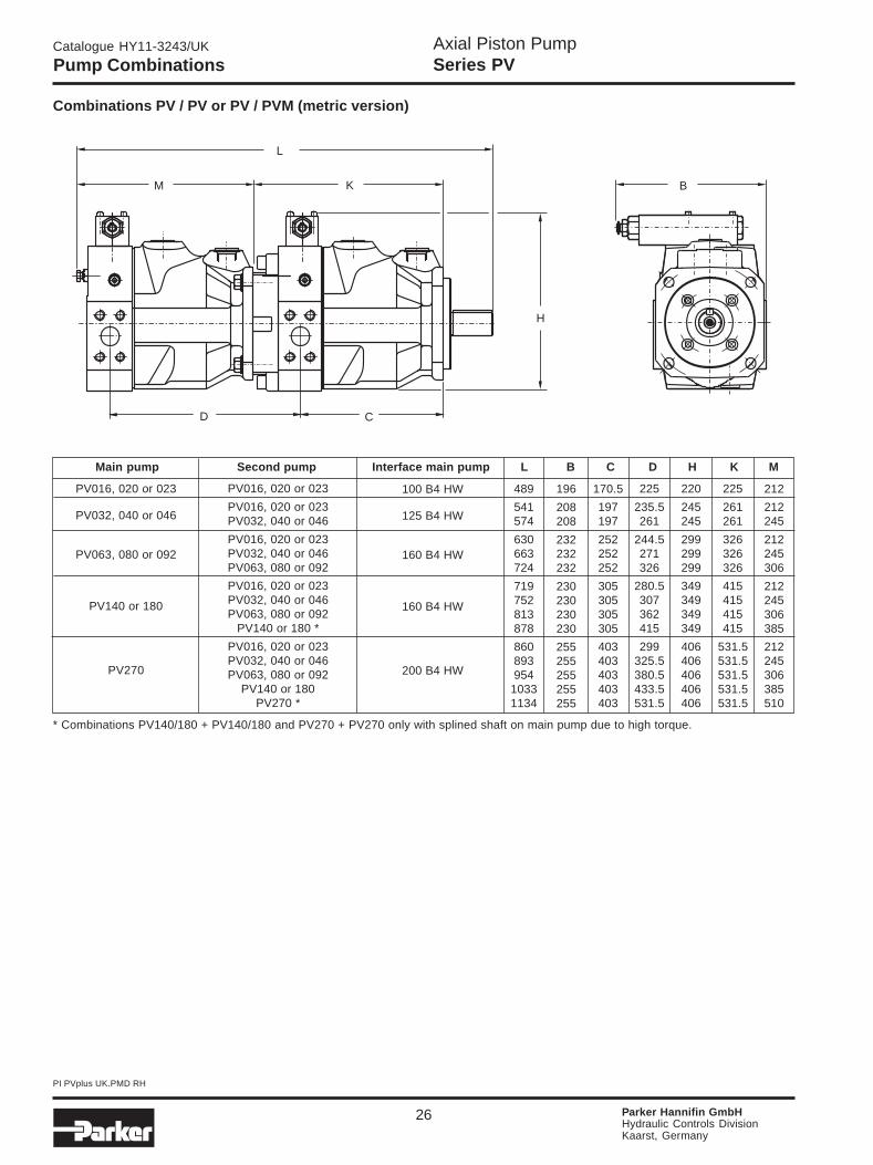
Main pump Second pump Interface main pump L B C D H K M
PV016, 020 or 023
PV016, 020 or 023PV032, 040 or 046
PV016, 020 or 023PV032, 040 or 046PV063, 080 or 092
PV016, 020 or 023PV032, 040 or 046PV063, 080 or 092
PV140 or 180 *
PV016, 020 or 023PV032, 040 or 046PV063, 080 or 092
PV140 or 180PV270 *
100 B4 HW
125 B4 HW
160 B4 HW
160 B4 HW
200 B4 HW
489
541574
630663724
719752813878
860893954
10331134
196
208208
232232232
230230230230
255255255255255
170.5
197197
252252252
305305305305
403403403403403
225
235.5261
244.5271326
280.5307362415
299325.5380.5433.5531.5
220
245245
299299299
349349349349
406406406406406
225
261261
326326326
415415415415
531.5531.5531.5531.5531.5
212
212245
212245306
212245306385
212245306385510
D C
L
M K
H
B
PV016, 020 or 023
PV032, 040 or 046
PV063, 080 or 092
PV140 or 180
PV270
Pump Combinations
Combinations PV / PV or PV / PVM (metric version)
* Combinations PV140/180 + PV140/180 and PV270 + PV270 only with splined shaft on main pump due to high torque.

Axial Piston PumpSeries PV
Catalogue HY11-3243/UK
PI PVplus UK.PMD RH
27 Parker Hannifin GmbHHydraulic Controls DivisionKaarst, Germany
Pump Combinations
Combinations PV / PGP511 or PGP517
L
K
H
M
D C
B
Model Ordering codePart Displacement Flow Weight
number [cm3/U] [l/min at 1500min-1] [kg]
PGP505PGP505A0040CA1H2NJ4J4B1B1 3319111251 4 6 2.3PGP505A0080CA1H2NJ4J4B1B1 3319111258 8 12 3.6
PGP511A0110CA1H2NL2L1B1B1 3349111186 11 16.5 3.6PGP511A0140CA1H2NL2L1B1B1 3349111187 14 21 3.8
PGP511PGP511A0160CA1H2NL2L1B1B1 3349111737 16 24 3.9PGP511A0190CA1H2NL2L1B1B1 3349111575 19 28.5 4.0PGP511A0220CA1H2NL2L2B1B1 3349111797 22 33 4.1PGP511A0270CA1H2NL2L2B1B1 3349111576 27 40.5 4.3PGP511A0330CA1H2NL2L2B1B1 3349111191 33 49.5 4.6
PGP517A0230CD1H3NL3L2B1B1 3339111151 23 34.5 8.3PGP517A0280CD1H3NL3L2B1B1 3339111484 28 42 8.5
PGP517PGP517A0330CD1H3NL3L2B1B1 3339111048 33 49.5 8.7PGP517A0380CD1H3NL3L2B1B1 3339111004 38 57 9.1PGP517A0520CD1H3NL3L3B1B1 3339111152 52 78 9.5PGP517A0700CD1H3NL3L3B1B1 3339111154 70 105 10.5
PGP350 PGP350A197EVAB2025 3239111027 83.6 125.4 25
Standard Gear Pumps for combination with PV
Main pump 2nd pump Interface main pump L* B C D* H K M
PGP511
PGP511
PGP517
PGP511
PGP517
PGP511
PGP517
PGP511
PGP517
86.7-132.3
86.7-132.3
122.8-161.2
86.7-132.3
122.8-161.2
86.7-132.3
122.8-161.2
86.7-132.3
122.8-161.2
363.7-409.3
415.7-461.3
451.8-490.2
504.7-550.3
540.8-579.2
593.7-639.3
629.8-668.2
733.2-778.8
769.3-807.7
199
211
211
233
233
233
233
258
258
170,5
197
197
252
252
305
305
403
403
97.1-119.9
106.6-129.4
122.8-161.2
86.7-132.3
122.8-161.2
86.7-132.3
122.8-161.2
86.7-132.3
122.8-161.2
220
245
245
301
301
349
349
406
406
225
261
261
326
326
415
415
531.5
531.5
PV016, 020 or 023
PV032, 040 or 046
PV063, 080 or 092
PV140 or 180
PV270
100 B4 HW
125 B4 HW
160 B4 HW
160 B4 HW
200 B4 HW
Dimensions PGP511* code H2 and PGP517* code H3
* For other dimensions of series PGP/PGM, see catalogue HY11-2500/UK, chapter 1, ‘Pumps & Motors’.

Axial Piston PumpSeries PV
Catalogue HY11-3243/UK
PI PVplus UK.PMD RH
28 Parker Hannifin GmbHHydraulic Controls DivisionKaarst, Germany
Pump Shaft Torque limit factor
D 17700
PV016-023E 17700K 17700L 20130
D 32680
PV032-046E 36380K 33810L 40250
D 77280
PV063-092E 72450K 67620L 83720
D 118400E 158760
PV140-180F 78750G 97650K 113400L 157500
D 119000
PV270E 159700K 170100L 236250
Shaft code
D 300 550 1320 2000 2000E 300 610 1218 2680 2680F -- -- -- 1320 --G -- -- -- 1640 --K 300 570 1150 1900 2850L 405 675 1400 2650 3980
Max. torque transmission 140 275 560 1100 1650cap. for rear mounted pump
PV016-023 PV032-046 PV063-092 PV140-180 PV270
Thru Drive, Shaft Load Limitations
Important notice
The max. allowable torque of the individual shaft mustnot be exceeded. For 2-pump combinations there is noproblem because PV series offers 100% thru torque. For3-pump combinations (and more) the limit torque couldbe reached or exceeded.
Therefore it is necessary to calculate the torque factorand compare it with the allowed torque limit factor in thetable.
Required: calculated torque factor
< torque limit factor
To make the necessary calculations easier and more userfriendly it is not required to calculate actual torque re-quirements in Nm and compare them with the shaft limi-tations. The table on the right shows limit factors that in-clude material specification, safety factors and conver-sion factors.
Max. transferable torque in [Nm] for different shafts options
Total torque factor of the combination= sum of individual torque factors of all pumps
Torque factor of any pump= p x Vg
The total torque factor is represented by the sum of theindividual torque factors of all pumps in the complete pumpcombination.
The torque factor of each individual pump is calculatedby multiplying the max. operating pressure p of the pump(in bar) with the max. displacement Vg of the pump (incm³/rev).

Axial Piston PumpSeries PV
Catalogue HY11-3243/UK
PI PVplus UK.PMD RH
29 Parker Hannifin GmbHHydraulic Controls DivisionKaarst, Germany
Compensators Dimensions
Ordering code seal kit, compensator
Remote pressure compensator, code FRCLoad-Sensing compensator, code FFC
Remote pressure comp. with interface NG6, code FR1Load-Sensing comp. with interface NG6, code FF1
Proportional p-Q-compensator, code FPR(for code FPV lower valve only without interface)
2-valve compensator, code FT1
LVDT for proportional compensator Pilot valve for horse power compensator
24
74.5
42.5
pressure pilot port P (code FRC)load-sensing
P-port P (code FFC)F
All control ports G1/4 optional M 12 x 1.5; ISO 6149-1(threads options 7 and 8) or 7/16-20 UNF (threads option 3)
T
P
40
32,531
31.5
load-sensing-port P (code FF1)(plugged for code FR1 )
F
2 x M5 - 10deep inpump body (see note above)
Interface NG6, CETOP 03
2 x M5 - 10 deep optional 10-32 UNC(threads option 3 and 7)
T
P
80
interface NG6, CETOP 03
load sensing port PF
40
50
40
49
interface NG6, CETOP 03
pump body
round connectorM 12 x 15 pins
69
pump body
34
Compensatorfor axial
piston pumpseries PV
SealSeal kit
SK PVC
Code Seal
N NBRV FPME EPR
The seal kit includes all seals for all single compensator options aswell as seals for LVDT and horse power pilot valve. For 2-valvecompensators two seal kits have to be ordered.Spare parts lists and ordering codes for replacement compensatorvalves see manual upon request.
Axial Piston PumpSeries PV
Catalogue HY11-3243/UK
PI PVplus UK.PMD RH
30 Parker Hannifin GmbHHydraulic Controls DivisionKaarst, Germany
p
Q
P L
S L
AP1PM
L AP1
= included
P L
S L
AP1PM
L
T
A
P
P1
T P
p
Q
= included
P L
S L
AP1PM
L AP1
PP
p
Q
= included
Standard pressurecompensatorcode F*S* = pressure rating
Remote pressurecompensator withinterface NG6 foraccessoriescode FR1
Remote pres-sure compensa-tor code FRC
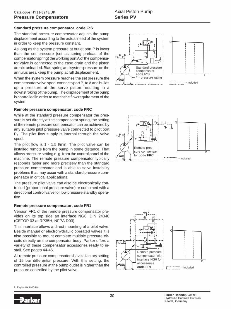
Standard pressure compensator, code F*S
The standard pressure compensator adjusts the pumpdisplacement according to the actual need of the systemin order to keep the pressure constant.
As long as the system pressure at outlet port P is lowerthan the set pressure (set as spring preload of thecompensator spring) the working port A of the compensa-tor valve is connected to the case drain and the pistonarea is unloaded. Bias spring and system pressure on theannulus area keep the pump at full displacement.
When the system pressure reaches the set pressure thecompensator valve spool connects port P
1 to A and builds
up a pressure at the servo piston resulting in adownstroking of the pump. The displacement of the pumpis controlled in order to match the flow requirement of thesystem.
Remote pressure compensator, code FRCWhile at the standard pressure compensator the pres-sure is set directly at the compensator spring, the settingof the remote pressure compensator can be achieved byany suitable pilot pressure valve connected to pilot portPP. The pilot flow supply is internal through the valvespool.
The pilot flow is 1 - 1.5 l/min. The pilot valve can beinstalled remote from the pump in some distance. Thatallows pressure setting e. g. from the control panel of themachine. The remote pressure compensator typicallyresponds faster and more precisely than the standardpressure compensator and is able to solve instabilityproblems that may occur with a standard pressure com-pensator in critical applications.
The pressure pilot valve can also be electronically con-trolled (proportional pressure valve) or combined with adirectional control valve for low pressure standby opera-tion.
Remote pressure compensator, code FR1
Version FR1 of the remote pressure compensator pro-vides on its top side an interface NG6, DIN 24340(CETOP 03 at RP35H, NFPA D03).
This interface allows a direct mounting of a pilot valve.Beside manual or electrohydraulic operated valves it isalso possible to mount complete multiple pressure cir-cuits directly on the compensator body. Parker offers avariety of these compensator accessories ready to in-stall. See pages 44-46.
All remote pressure compensators have a factory settingof 15 bar differential pressure. With this setting, thecontrolled pressure at the pump outlet is higher than thepressure controlled by the pilot valve.
Pressure Compensators

Axial Piston PumpSeries PV
Catalogue HY11-3243/UK
PI PVplus UK.PMD RH
31 Parker Hannifin GmbHHydraulic Controls DivisionKaarst, Germany
p
Q
T P
P L
S L
AP1PM
L
T
A
P
P1
PF
= included
p
Q
P L
S L
AP1PM
L AP1
PF
= included
2-valve Load-Sens.compensator withinterface NG6 foraccessoriescode FT1
Load-Sensingcompensatorcode FFCexternal orifice andpressure pilot valve
Load-Sensingcompensatorcode FFC
Load-Sensingcompensator withinterface NG6 foraccessoriescode FF1
P L
S L
AP1PM
L
Ø0.8
AP1
PF
p
Q
P L
S L
AP1PM
L
T
A
P
P1
PF
T P
= included
Load-Sensing Compensators
Shown above is load-sensing compensator, code FF1with an NG6 interface on top of the control valve. Thatallows direct mounting of a pilot valve for pressure com-pensation. This version includes the pilot orifice.
Due to the interaction of flow and pressure compensationthis package has not the "ideal" control characteristic.The deviation is caused by the pilot valves characteristic.
If a more accurate pressure compensation is required,the 2-valve load-sensing compensator code FT1 canbe used. The circuit diagram of this version is shown left.
Here the interaction of the two control functions is avoidedby using two separate control valves for flow and pres-sure compensation.
The 2-valve compensator is equipped with an interfaceNG6 on the compensators top side.
Load-Sensing compensator, code FFC
The load-sensing compensator has an external pilotpressure supply. Factory setting for the differential pres-sure is 10 bar. The input signal to the compensator is thedifferential pressure at a main stream resistor. A load-sensing compensator represents mainly a flow control forthe pump output flow, because the compensator keepsthe pressure drop at the main stream resistor constant.
A variable input speed or a varying load(-pressure) hasconsequently no influence on the output flow of the pumpand the speed of the actuator.
By adding a pilot orifice (Ø 0.8 mm) and a pressure pilotvalve pressure compensation can be added to the flowcontrol function. See the circuit diagram below, left.

Axial Piston PumpSeries PV
Catalogue HY11-3243/UK
PI PVplus UK.PMD RH
32 Parker Hannifin GmbHHydraulic Controls DivisionKaarst, Germany
Hydraulic-mechanical horse power compensatorThe hydraulic-mechanical horse power compensatorconsists of a modified remote pressure compensator(Code *L*) or of a modified load-sensing compensator(Code *C*) and a pilot valve. This pilot valve is integratedinto the pump and is adjusted by a cam sleeve. The camsleeve has a contour that is designed and machined forthe individual displacement and the nominal horse powersetting.At a large displacement the opening pressure (given bythe cam sleeve diameter) is lower than at small displace-ments. This makes the pump compensate along aconstant horse power (torque) curve (see diagrams onopposite page).For all nominal powers of standard electrical motorsParker offers a dedicated cam sleeve. The exchange ofthis cam sleeve (e. g.: to change horse power setting) caneasily be done without disassembly of the pump.On top of that an adjustment of the horse power settingcan be done within certain limits by adjusting the preloadof the pilot control cartridge spring . That allows anadjustment of a constant horse power setting for otherthan the nominal speeds (1500 min-1) or for other horsepowers.
Horse powercomp., pilot flowinternal interfaceon topcode *LA
Horse powercompensator,pilot flow internalcode *LB
Horse power comp.,pilot flow internalpressure pilot valveincludedcode *LC
Horse powercompensator,pilot flow externalfor load-sensingcode *CB
Horse powercomp., pilot flowexternal for load-sensing, pilot valveincluded code *CC
Ordering code for the horse power optionThe first digit designates the horse power setting:Code B= 3.0 kW etc. up toCode 3 = 132.0 kWThe second digit designates the pilot flow source:Code L internal pilot pressure, remote pressure func-
tion.Code C external pilot pressure, combines horse power
compensation with load-sensing compensa-tion.
The third digit designates the possibility to adjust theoverriding pressure compensation:Code A comes with a top side NG6/D03 interface on
the control valve to mount any suitable pilotvalve or Parker pump accessories.
Code B has a threaded pilot port Pp (G1/4) to connecta remote pilot valve with piping.
Code C includes a pilot valve for manual pressureadjustment. Max. setting: 350 bar.
Page 33 shows typical control characteristics and theavailable horse power settings for the different pumpsizes and displacements.
Horse Power Compensators

Axial Piston PumpSeries PV
Catalogue HY11-3243/UK
PI PVplus UK.PMD RH
33 Parker Hannifin GmbHHydraulic Controls DivisionKaarst, Germany
Characteristic curves, horse power compensators
The diagrams shown are only valid for the following working conditions:Speed : n = 1500 rev/minTemperature : t = 50°C
Fluid : HLP, ISO VG46Viscosity : ν = 46 mm2/s at 40°C
Horse Power Compensators, Diagrams
Axial Piston PumpSeries PV
Catalogue HY11-3243/UK
PI PVplus UK.PMD RH
34 Parker Hannifin GmbHHydraulic Controls DivisionKaarst, Germany
Electrohydraulic p-Q Control
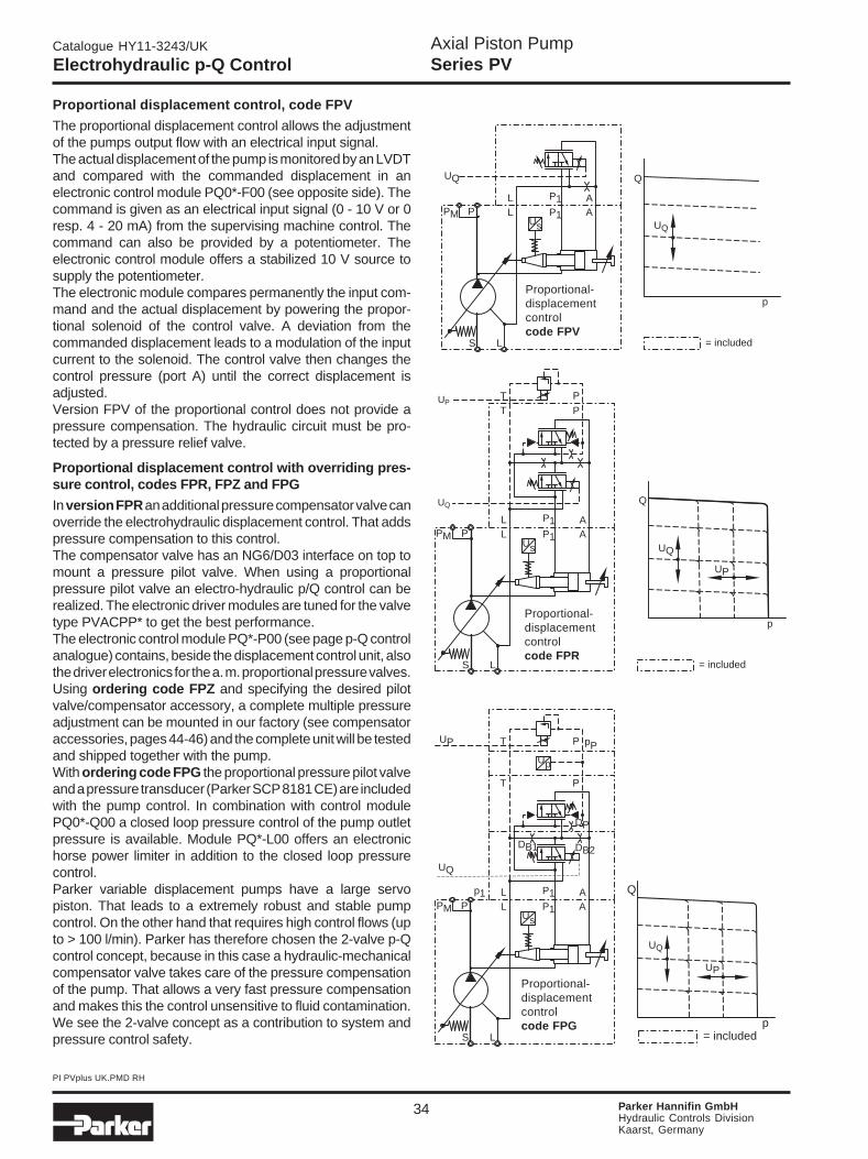
Proportional displacement control, code FPV
The proportional displacement control allows the adjustmentof the pumps output flow with an electrical input signal.The actual displacement of the pump is monitored by an LVDTand compared with the commanded displacement in anelectronic control module PQ0*-F00 (see opposite side). Thecommand is given as an electrical input signal (0 - 10 V or 0resp. 4 - 20 mA) from the supervising machine control. Thecommand can also be provided by a potentiometer. Theelectronic control module offers a stabilized 10 V source tosupply the potentiometer.The electronic module compares permanently the input com-mand and the actual displacement by powering the propor-tional solenoid of the control valve. A deviation from thecommanded displacement leads to a modulation of the inputcurrent to the solenoid. The control valve then changes thecontrol pressure (port A) until the correct displacement isadjusted.Version FPV of the proportional control does not provide apressure compensation. The hydraulic circuit must be pro-tected by a pressure relief valve.
p
Q
UP
UQ
T P
P L
S L
AP1PMsU
L
T
A
P
P1
UP
UQ
= included
P L
S L
AP1PMs
p
U
U
L
T
A
P
P1
T P
DB1 DB2
DP
p1
pP
UP
UQ
UP
UQ
Q
p= included
P L
S L
AP1PMsU
L AP1
UQ
p
Q
UQ
= included
Proportional-displacementcontrolcode FPV
Proportional-displacementcontrolcode FPR
Proportional-displacementcontrolcode FPG
Proportional displacement control with overriding pres-sure control, codes FPR, FPZ and FPG
In version FPR an additional pressure compensator valve canoverride the electrohydraulic displacement control. That addspressure compensation to this control.The compensator valve has an NG6/D03 interface on top tomount a pressure pilot valve. When using a proportionalpressure pilot valve an electro-hydraulic p/Q control can berealized. The electronic driver modules are tuned for the valvetype PVACPP* to get the best performance.The electronic control module PQ*-P00 (see page p-Q controlanalogue) contains, beside the displacement control unit, alsothe driver electronics for the a. m. proportional pressure valves.Using ordering code FPZ and specifying the desired pilotvalve/compensator accessory, a complete multiple pressureadjustment can be mounted in our factory (see compensatoraccessories, pages 44-46) and the complete unit will be testedand shipped together with the pump.With ordering code FPG the proportional pressure pilot valveand a pressure transducer (Parker SCP 8181 CE) are includedwith the pump control. In combination with control modulePQ0*-Q00 a closed loop pressure control of the pump outletpressure is available. Module PQ*-L00 offers an electronichorse power limiter in addition to the closed loop pressurecontrol.Parker variable displacement pumps have a large servopiston. That leads to a extremely robust and stable pumpcontrol. On the other hand that requires high control flows (upto > 100 l/min). Parker has therefore chosen the 2-valve p-Qcontrol concept, because in this case a hydraulic-mechanicalcompensator valve takes care of the pressure compensationof the pump. That allows a very fast pressure compensationand makes this the control unsensitive to fluid contamination.We see the 2-valve concept as a contribution to system andpressure control safety.

Axial Piston PumpSeries PV
Catalogue HY11-3243/UK
PI PVplus UK.PMD RH
35 Parker Hannifin GmbHHydraulic Controls DivisionKaarst, Germany
Electrohydraulic p-Q Control FP* / UP*
Beside the more compact and less vibration sensitive arrangement the elbow manifold version has moreadvantages:
All elements (compensator valves, pilot valve, pressuresensor) can be removed and serviced separately.
The valve bodies of the compensator valves are standardversions and no longer the special sandwich style versions(simplified logistics).
New version of electrohydraulic displacement and pressure control
PV046R1K1T1NFPGPump with electrohydraulic displacement and closed looppressure control
PV046R1K1T1NUPGPump with electrohydraulic displacement and closedloop pressure control with elbow manifold
Since shortly a new and more compact version of the p-Q-control for the PVplus is available. The two figures belowcompare the current and the new version. The left handside image shows a PV046 with compensator code...FPG. With this ordering code the pump is equipped withan electro hydraulic displacement control and anoverriding closed loop pressure control.
In version ...FPG the sandwich style mounting of thecompensator valves, pilot valve and transducer leads to
a high „tower“ of control elements. This has caused insome cases a space problem.
Therefore the version with an „elbow“ manifold - shown inthe right figure - has been developed. A manifold on thecompensator interface of the pump allows horizontalmounting of all control and pilot elements without stacking.The compensator ordering code changes from ...FPG to...UPG for this new version (see ordering code“electrohydraulic compensators“ on page 6).

Axial Piston PumpSeries PV
Catalogue HY11-3243/UK
PI PVplus UK.PMD RH
36 Parker Hannifin GmbHHydraulic Controls DivisionKaarst, Germany
Size Dimension [mm] A B C D D1 D2 E F G H K L N
BG1 PV016-PV023 66 132 85 122 126.5 171.5 256.5 197.5 174.1 396.5 174 80 26.5BG2 PV032-PV046 78 156 85 122 126.5 171.5 256.5 227.0 174.1 421.5 199 92 33.0BG3 PV063-PV092 102 204 85 122 126.5 171.5 256.5 287.0 174.1 475.5 253 118 40.0BG4 PV140-PV180 100 200 85 122 126.5 171.5 256.5 350.0 174.1 525.5 303 145 58.0BG5 PV270 125 250 85 122 126.5 171.5 256.5 472.5 174.1 582.5 360 176 85.5
Electrohydraulic p-Q Control FP*
DimensionsAxial piston pump series PV with p-Q-control,compensator ordering code ...FPG (closed loop pressurecontrol)
NoteFor version without pressure sensor (open loop pressurecontrol) dimensions G and H are shorter by 40 mm anddimension D
2 is not applicable.

Axial Piston PumpSeries PV
Catalogue HY11-3243/UK
PI PVplus UK.PMD RH
37 Parker Hannifin GmbHHydraulic Controls DivisionKaarst, Germany
Size Dimension [mm] A B C D E F G H K L M N P R
BG1 PV016-PV023 66 132 94.5 149.5 243.9 197.5 91.1 313.3 174 80 305 26.5 134 234BG2 PV032-PV046 78 156 94.5 149.5 243.9 227.0 91.1 438.3 199 92 328 33.0 134 234BG3 PV063-PV092 102 204 94.5 149.5 243.9 287.0 91.1 392.3 253 118 381 40.0 134 234BG4 PV140-PV180 100 200 94.5 149.5 243.9 350.0 91.1 442.3 303 145 426 58.0 134 234BG5 PV270 125 250 94.5 149.5 243.9 472.5 91.1 499.3 360 176 521 85.5 134 234
Electrohydraulic p-Q Control UP*
DimensionsAxial piston pump series PV with p-Q-control,compensator ordering code ...UPG (closed loop pressurecontrol).

Axial Piston PumpSeries PV
Catalogue HY11-3243/UK
PI PVplus UK.PMD RH
38 Parker Hannifin GmbHHydraulic Controls DivisionKaarst, Germany
Ordering code analogue electronic module
Technical data Diagrams
Response times
Size TA [ms] TR [ms]
PV023 50 50PV046 70 70PV092 90 90PV180 150 150PV270 200 200
Pumpvariation
Pumpamplifier
Designseries
PQ
Modulevariation
00
Code Pump variation
01 PV 016/020/02302 PV 032/040/04603 PV 063/080/09204 PV 140/18005 PV 270
Electronic modul PQ0*-P00 to operate the p-Q control for PV pumps
The electronic modules to power the displacement con-trol and the pressure control are snap-on type modules.They can be mounted on installation rails according to EN50022. A card holder is not required.The modules have potentiometers to adjust up and downramps (ramp time up to 5s) and a min. and max. adjust-ment for optimum resolution and sensitivity as requiredby the application.They comply with the latest legal requirements andconfirm to European law. They are EMC approved andcorrespond to the CE guidelines.
Electronic Module PQ* (analogue)
Code Variation
F flow control onlyP flow control and pressure adjustmentQ flow and pressure control
L flow and pressure control with horsepower limitation
NOTE!The electronic modules are not included in the pumpcompensator. Please order separately.
15 bar
± 0.75 %
Minimum control pressure required(at internal pressure supply= minimum system pressure)Repeatability
Proportional flow compensator(solenoid):
- nominal voltage- environmental temperature- duty cycle- protection class- connector
Inductive position feedback (LVDT):
- supply voltage- current requirement- output voltage- environmental temperature- load to output signal
- connector
16 V50 °C100 %IP54ISO 4400
18 to 36 VDC<50 mA3.5 to 11.5 VDC0 to 50 °C> 5 kOhm (short circuit pro-tected)round connector M12x1.5 pin
More technical information on these modules can be found incatalogue HY11-2500/UK, chapter 10, ‘Electronics’.

Axial Piston PumpSeries PV
Catalogue HY11-3243/UK
PI PVplus UK.PMD RH
39 Parker Hannifin GmbHHydraulic Controls DivisionKaarst, Germany
Electronic Module PQDXXA (digital)
The digital control module code PDDXXA-Z00 is alsodesigned for rail mounting like the analog modules.
Ordering code
OptionFor all framesizes series PV
Digital controlmodule for p-Q
control
Version A
Features
• Digital control circuit• Parameter setting via RS-232 interface• All settings (ramps, MIN/MAX, control parameters) can
be stored digitally and recalled from a PC to duplicatesettings to other modules
• Ramp time up to 60 seconds• Compatible to the relevant european EMC specificati-
ons• Easy to use PC based setup software• Covers all displacements from 16 to 270 cm³/rev
• Covers all functions: displacement control, displace-ment control with open loop pressure control, displace-ment control with closed loop pressure control and dis-placement control with closed loop pressure controland electronic horse power limitation.
Technical data
PQD XX A
Note
More technical information on these modules can be found incatalogue HY11-2500/UK, chapter 10, ‘Electronics’.
Please order the“interface cable to PC“
separately.Ordering code:
PQDXXA-KABEL
Z00
Programming softwareThe programming of the p-Q-control module is done in aneasy to learn mode. To select the pump model and sizeand to set the control paramters the program ProPVplusmust be started. This program runs under WINDOWS® 95and higher.The latest version of this software can be downloaded atthe following internet address:
http://www.parker.com/euro_hcd
The software offers the following features:A TERMINAL window to set or read out the control param-eters of the module. Settings as well as commentsentered in the terminal window can be stored also in RTF-format (opens e. g. under WORD or other text editors)A MONITOR window allows to display process variablesin numerical format.An OSZILLOSKOP window displays process variables ascurves. The oscilloscope offers a start - stop function. Theimages can be saved and stored e. g. for import into otherprograms.Features• Display and documentation of parameter sets• Save ond reload of optimized parameter sets• Offers oscilloscope function for easy performance evalu-
ation and optimization• Pre-optimized parameter sets for all PVplus piston pump• Sizes already in E2PROM memory
Mounting style Snap-on mounting for EN50022rail
Body material PolycarbonateInflammation class V2...V0 acc. UL 94Mounting position anyEnv. temperature range [°C] -20...+55Protection class IP 20 acc. DIN 40 050Weight [g] 160Duty ratio [%] 100Supply voltage [V] 18...30VDC, ripple <5% eff.Rush in current [A] 22 for 0.2 msCurrent consumption [A] < 4 for p/Q-control
< 2 for Q-controlResolution [%] 0.025 (horse power 0.1)Interface RS232C, 9600 baud, 3.5 mm cinchEMC EN 50 081-2, EN 50 082-2Connctors Screw terminals 0.2...2.5 mm²
plug in styleCables [mm²] 1.5 (AWG 16)
overall braid shield, for supply andsolenoid connection 0.5 mm²(AWG 20) overall braid shield, forsensor and command signal con-nections
Max. cable length [m] 50
For programming the module via PC, an interface cable is needed, toorder seperately.
Axial Piston PumpSeries PV
Catalogue HY11-3243/UK
PI PVplus UK.PMD RH
40 Parker Hannifin GmbHHydraulic Controls DivisionKaarst, Germany
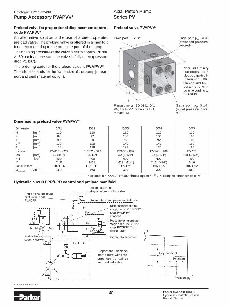
Dimension BG1 BG2 BG3 BG4 BG5H [mm] 110 110 110 110 130B [mm] 92 92 100 100 154T [mm] 80 80 92 92 105L 2) [mm] 120 120 140 140 160T1 [mm] 116 116 137 137 150for size PV016 - 023 PV032 - 046 PV063 - 092 PV140 - 180 PV270DN [mm] 19 (3/4“) 25 (1“) 32 (1 1/4“) 32 (1 1/4“) 38 (1 1/2“)PN [bar] 400 400 400 400 400M M10 M12 M12 (M14*) M12 (M14*) M16valve insert DIN E16 DIN E16 DIN E25 DIN E25 DIN E32Qnominal [l/min] 160 160 300 300 550
Dimensions preload valve PVAPVV*
* optional for PV063 - PV180, thread option 4; 2) L = clamping length for bolts M
Drain port L, G1/4“
Hydraulic circuit FPR/UPR control and preload manifold
Preload valve for proportional displacement control,code PVAPVV*An alternative solution is the use of a direct operatedpreload valve. The preload valve is offered in a manifoldfor direct mounting to the pressure port of the pump.The opening pressure of the valve is set to approx. 20 bar.At 30 bar load pressure the valve is fully open (pressuredrop <1 bar).The ordering code for the preload valve is PVAPVV*.Therefore * stands for the frame size of the pump (thread,port and seal material option).
Proportional displace-ment control with pres-sure compensationand preload valve
Pump Accessory PVAPVV*
Preload valve PVAPVV*
Flanged ports ISO 6162: DN,PN; fits to PV frame size BG;threads: M
Note: All auxiliarymanifolds canalso be supplied inUS-version (UNCthreads and UNFports) and withports according toISO 6149.
Gage por t p2, G1/4“(outlet pressure, cove-red)
Gage port p1, G1/4“(preloaded pressure,covered)

Axial Piston PumpSeries PV
Catalogue HY11-3243/UK
PI PVplus UK.PMD RH
41 Parker Hannifin GmbHHydraulic Controls DivisionKaarst, Germany
Pump Accessory PVAPSE*
Dimension BG1 BG2 BG3 BG4 BG5
B [mm] 110 110 110 110 154H [mm] 92 92 100 100 120T [mm] 80 80 92 92 105B1 [mm] 150 150 150 150 199H1 [mm] 133 133 141 141 143for size PV016 - 023 PV032 - 046 PV063 - 092 PV140 - 180 PV270DN [mm] 19 (3/4“) 25 (1“) 32 (1 1/4“) 32 (1 1/4“) 38 (1 1/2“)PN [bar] 400 400 400 400 400M M10 M12 M12 (M14*) M12 (M14*) M16valve insert DIN E16 DIN E16 DIN E16 DIN E16 DIN E25Qnominal [l/min] 160 160 160 160 300G (port T) 1/2“ 1/2“ 1/2“ 1/2“ 3/4“
Dimensions quick unload manifold PVAPSE*
* optional for PV063 - PV180, thread option 4Hydraulic circuit FPS/UPS control with quick unload manifold
Quick unload manifold for proportional pump control, codePVAPSE*When working with a proportional pressure control on variabledisplacement pumps, pressure decrease can be slow. Whenthe pump strokes to deadhead, there is no active pressure relief.To achieve a response similar to a valve controlled system, thequick unload manifold can be mounted to the pump outlet.This manifold includes a cartridge valve with a 4 bar springpreload. The pilot pressure supply for the compensator valve ispassing this cartridge valve and creates a pressure drop acrossthe poppet. At normal working conditions this pressure dropdoes not exceed 3 bar and the poppet stays closed. In a dynamicresponse situation the pressure drop can exceed 4 bar and thecartridge actively reduces the system pressure acoording tothe setting of the proportional pilot valve.As the pilot pressure is fed through the quick unload manifold,the compensator needs no orifice in the spool. Ordering codefor the proportional displacement and pressure control forcombination with the quick unload manifold is FPS for pressurecompensation and FPT for closed loop pressure control(pressure transducer and proportional pressure pilot valveincluded).
Proportional displace-ment control with pres-sure compensationand quick unload mani-fold
Quick unload manifold
Also availablein US-version(UNC threadsand UNF ports)and with portsaccording toISO 6149.
Flange port ISO6162, DN, PN; fitsto PV frame sizeBG; thread M
Gage port MpP,
Return port T, thread G;
Control port pP, G1/4“ (to compensa-tor)
Max. pressure pilot valve
Axial Piston PumpSeries PV
Catalogue HY11-3243/UK
PI PVplus UK.PMD RH
42 Parker Hannifin GmbHHydraulic Controls DivisionKaarst, Germany
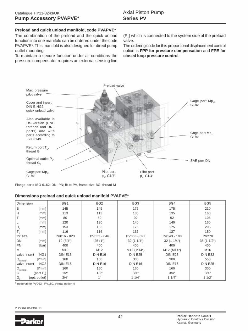
Pump Accessory PVAPVE*
Dimension BG1 BG2 BG3 BG4 BG5
B [mm] 145 145 175 175 210H [mm] 113 113 135 135 160T [mm] 80 80 92 92 105L [mm] 120 120 140 140 160H1 [mm] 153 153 175 175 205T1 [mm] 116 116 137 137 150for size PV016 - 023 PV032 - 046 PV063 - 092 PV140 - 180 PV270DN [mm] 19 (3/4“) 25 (1“) 32 (1 1/4“) 32 (1 1/4“) 38 (1 1/2“)PN [bar] 400 400 400 400 400M M10 M12 M12 (M14*) M12 (M14*) M16valve insert NG1 DIN E16 DIN E16 DIN E25 DIN E25 DIN E32Qnominal [l/min] 160 160 300 300 550valve insert NG2 DIN E16 DIN E16 DIN E16 DIN E16 DIN E25Qnominal [l/min] 160 160 160 160 300G (port TE) 1/2“ 1/2“ 3/4“ 3/4“ 3/4“G
2(opt. outlet) 3/4“ 1“ 1 1/4“ 1 1/4“ 1 1/2“
Flange ports ISO 6162; DN, PN; fit to PV, frame size BG; thread M
Dimensions preload and quick unload manifold PVAPVE*
* optional for PV063 - PV180, thread option 4
Preload and quick unload manifold, code PVAPVE*The combination of the preload and the quick unloadfunction into one manifold can be ordered under the codePVAPVE*. This manifold is also designed for direct pumpoutlet mounting.To maintain a secure function under all conditions thepressure compensator requires an external sensing line
(Ps) which is connected to the system side of the preload
valve.The ordering code for this proportional displacement controloption is FPP for pressure compensation and FPE forclosed loop pressure control.
Max. pressurepilot valve
Cover and insertDIN E NG2quick unload valve
Also available inUS-version (UNCthreads and UNFpor ts) and withports according toISO 6149.
Return port TE,thread G
Optional outlet P2,thread G2
Gage port MpP,G1/4“
Preload valve
Gage port Mp1,G1/4“
Gage port Mp2,G1/4“
Pilot portpS, G1/4“
Pilot portpP, G1/4“
SAE port DN

Axial Piston PumpSeries PV
Catalogue HY11-3243/UK
PI PVplus UK.PMD RH
43 Parker Hannifin GmbHHydraulic Controls DivisionKaarst, Germany
Hydraulic circuit FPS/UPS control with preload and quick unload manifold
Accessories for axialpiston pump, PV
series, pressure portmounting
Function Framesize
Threadoption
Seal
Code Seal
N NBRV FPME EPDM
PVAP
Ordering code pump accessories
Proportional displace-ment control with pres-sure compensationand preload plus quickunload manifold
Code Function
VV Preload manifold
SEQuick unload
manifoldPreload and
VE quick unloadmanifold
Code Size
1 PV016-0232 PV032-0463 PV063-0924 PV140-1805 PV270
Pump Accessory PVAPVE* / Ordering Code
1) Drain, gage and control ports2) Mounting threads3) For PV063-PV180 only: pressure
port 1 1/4" with M14 instead of M12
Code Ports1) Threads2)
1 BSPP Metric3 UNF UNC43) BSPP Metr. M147 ISO 6149 UNC8 ISO 6149 Metric

Axial Piston PumpSeries PV
Catalogue HY11-3243/UK
PI PVplus UK.PMD RH
44 Parker Hannifin GmbHHydraulic Controls DivisionKaarst, Germany
Hydraulic Circuit / Ordering Examples
Ordering Examples
Example 1 Example 2PV pump with fast response remote pressure control,relief valve with 2 pressure stages, electrical pressureselection, nitrile seals, spindle adjustment, 24 VDC sole-noid, accessories fitted:
PV * * * * * * * * FRZ; Z = PVAC2PCMNSJW35
Same pump, accessories not fitted:PV * * * * * * * * FR1; 1 = PVAC2PCMNSJW35
Example 3Usable for horsepower control and proportional volumecontrol, too.
PV * * * * * * * * FRZ; Z = PVAC2PCMNSJW35
Schematics PVAC1P* Schematics PVAC1E*
Schematics PVAC2P* Schematics PVAC2E

Axial Piston PumpSeries PV
Catalogue HY11-3243/UK
PI PVplus UK.PMD RH
45 Parker Hannifin GmbHHydraulic Controls DivisionKaarst, Germany
Ordering Code / Dimensions
For spare parts and replacement kits see manual upon request.Please order plugs separately. See accessories in catalogue HY11-2500/UK, chapter 2, ‘DC Valves’.
PVAC2P* PVAC2E*/2M*
PVAC1E*PVAC1P*
AdjustmentCode S
AdjustmentCode L
DC solenoid 205AC solenoid 190
DC solenoid 205AC solenoid 190
Lowpressure
Highpressure
DC solenoid 241AC solenoid 211
Lowpressure
Highpressure
Dimensions
Pressure relief valve mounted on 2-valve pressure-flow compensatortype T
2-pressure relief valve, electrical selection, mounted on compensatortype R or F
Pressure relief valve, electrical unloading, mounted on compensatortype R or F
2-pressure relief valve, electrical selection and unloading, mounted oncompensator type R or F
Code Seals
N NBRV FPME EPR
ACPV
Function Solenoid Designseries
ForPV pump
series
AdjustmentSealsAccessoriesfor
compensa-tors
Solenoidacces-sories
Mountingbolts
(not requiredfor order)
Nominalpressure350 bar
1)
35
Code Function
1P Max. pressure relief
1E1 pressure,
electrical unloading
2P2 pressures,
electrical selection
2 pressures + stands2E electrical selection
low pressure default
2 pressures + stands2M electrical selection
stand by default
Code Mounting bolts
C For single compensators type R or FT For 2-valve-compensator type TS Without bolts 2)
P For code FP*U For code UP*
Code Solenoid accessories
omit For function 1P
CConduit box
with free wires
WDIN plug socket
without plug
Code Solenoid voltage
omit For function 1P
Y 110V/50Hz - 120V/60Hz
T 220V/50Hz - 240V/60Hz
J 24V DC
Code Adjustment
SSpindle
with lock nut
L DIN lock1) Other pressures on request.
Code Threads
M metricS SAE / UNC
Threads
2) Mounting bolts code “S“ only in combination with thread option “M“.

Axial Piston PumpSeries PV
Catalogue HY11-3243/UK
PI PVplus UK.PMD RH
46 Parker Hannifin GmbHHydraulic Controls DivisionKaarst, Germany
Accessories
Code Seal
N NBRV FPME EPDM
Ordering code proportional pressure control valve
ACPV
Prop.pressure
valve
Pumpseries PV
SealAccessoriesfor controller
PP
Code Nominal pressure
35 350 bar42 420 bar
Nominalpressure
Mountingbolts
Schematic PVACPP* Dimensions PVACPP*
Proportional pressure control valveProportional pressure pilot valves of series PVACPP* arepowered by external electronic modules (e. g. PCD00*,see catalogue HY11-2500/UK, chapter10, ‘Electronics’).
They allow an infinite electronic adjustment of the pumpscompensating pressure. The different pressure ratingscome with different control orifices in the pilot valve.
Threadoption
Code Thread option
M MetricS SAE / UNC
Code Mounting bolts/ports
C For single controller type R or F
T For double valve contr. type T
S Without bolts*
D For code FPD, FPS, FPP
P For code FPG, FPE, FPT
U For code UP*
* Mounting bolts code “S“only in combination withthread option “M“
Designseries
(not requiredfor order)
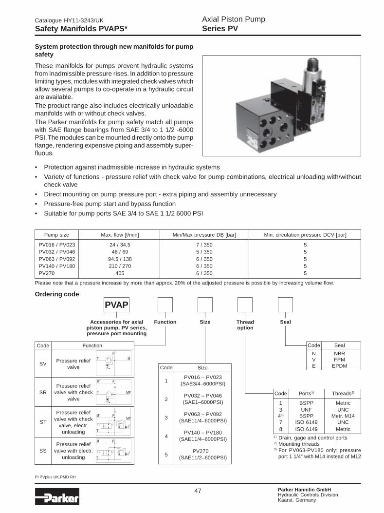
Axial Piston PumpSeries PV
Catalogue HY11-3243/UK
PI PVplus UK.PMD RH
47 Parker Hannifin GmbHHydraulic Controls DivisionKaarst, Germany
Size
PV016 – PV023(SAE3/4–6000PSI)
PV032 – PV046(SAE1–6000PSI)
PV063 – PV092(SAE11/4–6000PSI)
PV140 – PV180(SAE11/4–6000PSI)
PV270(SAE11/2–6000PSI)
Code
1
2
3
4
5
Ordering code
Accessories for axialpiston pump, PV series,pressure port mounting
Function Size Threadoption
Seal
Code Ports1) Threads2)
1 BSPP Metric3 UNF UNC43) BSPP Metr. M147 ISO 6149 UNC8 ISO 6149 Metric
Code Seal
N NBRV FPME EPDM
PVAP
Code
SV
Function
SS
ST
SR
Pump size Max. flow [l/min] Min/Max pressure DB [bar] Min. circulation pressure DCV [bar]
PV016 / PV023 24 / 34,5 7 / 350 5PV032 / PV046 48 / 69 5 / 350 5PV063 / PV092 94.5 / 138 6 / 350 5PV140 / PV180 210 / 270 6 / 350 5PV270 405 6 / 350 5
Pressure reliefvalve with check
valve
Pressure reliefvalve with electr.
unloading
Pressure reliefvalve
Pressure reliefvalve with check
valve, electr.unloading
Safety Manifolds PVAPS*
1) Drain, gage and control ports2) Mounting threads3) For PV063-PV180 only: pressure
port 1 1/4" with M14 instead of M12
Please note that a pressure increase by more than approx. 20% of the adjusted pressure is possible by increasing volume flow.
System protection through new manifolds for pumpsafety
These manifolds for pumps prevent hydraulic systemsfrom inadmissible pressure rises. In addition to pressurelimiting types, modules with integrated check valves whichallow several pumps to co-operate in a hydraulic circuitare available.The product range also includes electrically unloadablemanifolds with or without check valves.The Parker manifolds for pump safety match all pumpswith SAE flange bearings from SAE 3/4 to 1 1/2 -6000PSI. The modules can be mounted directly onto the pumpflange, rendering expensive piping and assembly super-fluous.
• Protection against inadmissible increase in hydraulic systems
• Variety of functions - pressure relief with check valve for pump combinations, electrical unloading with/withoutcheck valve
• Direct mounting on pump pressure port - extra piping and assembly unnecessary
• Pressure-free pump start and bypass function
• Suitable for pump ports SAE 3/4 to SAE 1 1/2 6000 PSI

Axial Piston PumpSeries PV
Catalogue HY11-3243/UK
PI PVplus UK.PMD RH
48 Parker Hannifin GmbHHydraulic Controls DivisionKaarst, Germany
Size b1 b2 b3 b4 h1 h2 h3 t M P 6000 PSI T O-ring
PVAPSV11 27 85 27.4 67 40 90 22.5 45 G 1/4 G/SAE 3/4 G 1/2 2-214
PVAPSV21 32 95 30 73.2 45 100 22.5 45 G 1/4 SAE 1 G 3/4 2-219
PVAPSV31 37 125 27 94.3 60 120 30 60 G 1/4 SAE 1 1/4 G 1 1/4 2-222
PVAPSV41 37 125 31 94.3 60 120 30 60 G 1/4 SAE 1 1/4 G 1 1/4 2-222
PVAPSV51 50 145 36 112.4 60 125 35 70 G 1/4 SAE 1 1/2 G 1 1/2 2-225
Mounting bolts not included in delivery.
Safety Manifolds PVAPS*
Option SV, pump safety manifold with pressure relief valve

Axial Piston PumpSeries PV
Catalogue HY11-3243/UK
PI PVplus UK.PMD RH
49 Parker Hannifin GmbHHydraulic Controls DivisionKaarst, Germany
Option SR, pressure relief with check valve
Size b1 b2 b3 b4 b5 h1 h2 h3 h4 t1 t2 d1 d2 M P 6000 PSI T O-ring
PVAPSR11 63,5 85 29 67,5 22,5 42 93 70 41 89 90 11 17 G 1/4 G/SAE 3/4 G 1/2 2-214
PVAPSR21 75 110 30,5 88,5 26 50 104 68 50 75 90 13 20 G 1/4 SAE 1 G 3/4 2-219
PVAPSR31 95,5 140 31 110,4 37 60 120 90 60 105 120 13 20 G 1/4 SAE 1 1/4 G 1 1/4 2-222
PVAPSR41 95,5 140 31 110,4 37 60 120 90 60 105 120 13 20 G 1/4 SAE 1 1/4 G 1 1/4 2-222
PVAPSR51 115 160 36,4 126 40 60 130 95 60 115 135 18 26 G 1/4 SAE 1 1/2 G 1 1/2 2-225
Mounting bolts included in delivery.
Safety Manifolds PVAPS*

Axial Piston PumpSeries PV
Catalogue HY11-3243/UK
PI PVplus UK.PMD RH
50 Parker Hannifin GmbHHydraulic Controls DivisionKaarst, Germany
Option ST, pressure relief with check valve, electr. unloading with/without check valve
Size b1 b2 b3 b4 b5 h1 h2 h3 h4 h5 t1 t2 t3 d1 d2 M P 6000 PSI T O-ring
PVAPST11 63.5 90 29 72.5 22.5 41 90 72 70 41 89 90 8 11 17 G 1/4 G/SAE 3/4 G 1/2 2-214
PVAPST21 74.5 110 50 80 26 50 100 124 70 50 90 105 96.5 13 20 G 1/4 SAE 1 G 3/4 2-219
PVAPST31 95.5 140 50 99 37 60 120 99.1 96 60 125 140 82.5 13 20 G 1/4 SAE 1 1/4 G 1 1/4 2-222
PVAPST41 95.5 140 50 99 37 60 120 99.1 96 60 125 140 82.5 13 20 G 1/4 SAE 1 1/4 G 1 1/4 2-222
PVAPST51 115 164 50 123 40 60 130 95.1 96 60 120 140 81 18 26 G 1/4 SAE 1 1/2 G 1 1/2 2-225
Mounting bolts included in delivery.
Safety Manifolds PVAPS*
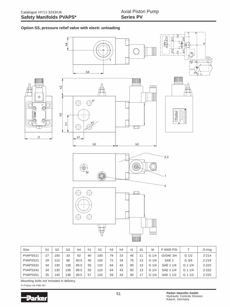
Axial Piston PumpSeries PV
Catalogue HY11-3243/UK
PI PVplus UK.PMD RH
51 Parker Hannifin GmbHHydraulic Controls DivisionKaarst, Germany
Option SS, pressure relief valve with electr. unloading
Size b1 b2 b3 b4 h1 h2 h3 h4 t1 d1 M P 6000 PSI T O-ring
PVAPSS11 27 100 33 82 40 100 79 23 46 11 G 1/4 G/SAE 3/4 G 1/2 2-214
PVAPSS21 29 110 88 80.5 45 100 72 34 75 13 G 1/4 SAE 1 G 3/4 2-219
PVAPSS31 34 130 138 89.5 55 110 64 43 90 13 G 1/4 SAE 1 1/4 G 1 1/4 2-222
PVAPSS41 34 130 138 89.5 55 110 64 43 90 13 G 1/4 SAE 1 1/4 G 1 1/4 2-222
PVAPSS51 35 140 138 99.5 57 120 59 43 90 17 G 1/4 SAE 1 1/2 G 1 1/2 2-225
Mounting bolts not included in delivery.
Safety Manifolds PVAPS*

Axial Piston PumpSeries PV
Catalogue HY11-3243/UK
PI PVplus UK.PMD RH
52 Parker Hannifin GmbHHydraulic Controls DivisionKaarst, Germany
Accessories
Bell housing, coupling and foot flange
Can be purchased at:
Raja orRahmer + Jansen GmbHVorthstr. 158775 Werdohl, GermanyTel.: (+2392) 5090, fax: (+2392) 4966
KTRKupplungstechnik GmbHRodder Damm48432 Rheine, GermanyTel.: (+5971) 798-0, fax: (+5971) 798443
Welding flange * Threaded flange *
* For further information about flanges see catalogue No. 4039/UK „Pressure Hydraulic Flanges“ (on request)
Can be purchased at:
SAE-flange connections, pipe connection in accordance to DIN 2353
Elbow SAE-flange connection WFS * Straight SAE-flange connection GFS *
Can be purchased at:
Parker Hannifin GmbHTube Fittings DivisionAm Metallwerk 933659 Bielefeld, GermanyTel.: (+521) 4048-0, fax: (+521) 4048280
Parker Hannifin GmbHTube Fittings DivisionAm Metallwerk 933659 Bielefeld, GermanyTel.: (+521) 4048-0, fax: (+521) 4048280

Axial Piston PumpSeries PV
Catalogue HY11-3243/UK
PI PVplus UK.PMD RH
53 Parker Hannifin GmbHHydraulic Controls DivisionKaarst, Germany
Fluid recommendations
Premium quality hydraulic mineral oil fluids are recom-mended, like H-LP oils to DIN 51524, part 2. The viscosityrange should be 25 to 50 mm2/s (cSt) at 50 0C.
Normal operating viscosity range between 12 and 100mm2/s (cSt). Maximum start-up viscositiy is 320 mm2/s(cSt). Operating temperature -10 to + 70 0C.
For other fluids such as phosphoric acid esters or forother operating conditions consult your Parker represen-tative for assistance.
Seals
NBR (nitrile) seals are used for operation with hydraulicfluids based on mineral oil. For synthetic fluids, as per-haps phosphoric acid esters, Fluorocarbon seals arerequired. Consult your Parker representative for assis-tance.
Drain line
The drain line must lead directly to the reservoir withoutrestriction. The drain line must not be connected to anyother return line. The end of the drain line must be belowthe lowest fluid level in the reservoir and as far away aspossible from the pump inlet line. This ensures that thepump does not empty itself when not in operation and thathot aireated oil will not be recirculated.
For the same reason, when the pump is mounted insidethe reservoir, the drain line should be arranged in such away that a siphon is created. This ensures that the pumpis always filled with fluid. The drain pressure must notexceed 2 bar. Drain line length should not exceed 2metres. Minimum diameter should be selected accordingto the port size and a straight low pressure fitting withmaximised bore should be used.
Installation and mountingHorizontal mounting: Outlet port side or top. Inlet port sideor bottom, drain port always uppermost.
Vertical mounting: Shaft pointing upwards.
Install pump and suction line in such a way that themaximum inlet pressure never exceeds 0.8 bar absolute.The inlet line should be as short and as straight aspossible. A short suction line cut to 450 is recommendedwhen the pump is mounted inside the reservoir, to im-prove the inlet conditions. All connections to be leak-free,as air in the suction line will cause cavitation, noise, anddamage to the pump.
Drain port
Compensation may cause short-term (20 to 30 ms) flowincrease, e.g. 30 l/min (PV 016 to 023), 40 l/min (PV 032to 046), 60 l/min (PV 063 to 092),80 l/min (PV 140 to 180)and/or 120 l/min (PV270). Please consider for dimen-sioning.
Shaft rotation and alignment
Pump and motor shafts must be aligned within 0.25mmT.I.R. maximum. A floating coupling must be used.Bellhousings and couplings can be ordered at manufac-turers listed in this catalogue. Please follow the couplingmanufacturer's installation instructions. Consult yourParker representative for assistance on radial load typedrives.
Start upPrior to start up, the pump case must be filled withhydraulic fluid (use case drain port). Initial start up shouldbe at zero pressure with an open circuit to enable thepump to prime. Pressure should only be increased oncethe pump has been fully primed.
Attention: Check motor rotation direction.
For more details see installation manual HY11-PVI016.
General Installation Information
Filtration
For maximum pump and system component functionabilityand life, the system should be protected from contamina-tion by effective filtration.
Fluid cleanliness should be in accordance with ISOclassification ISO 4406:1999. The quality of filter ele-ments should be in accordance with ISO standards.
Minimum requirement for filtration rate x (mm):
General hydraulic systems for satisfactory operation:
Class 20/18/15, to ISO 4406:1999
x = 25 µm (ß25 ≥ 75) to ISO 4572
Hydraulic systems with maximised component life andfunctionability:
Class 18/16/13, to ISO 4406:1999
x = 10 µm (ß10
≥ 75) to ISO 4572
It is recommended to use return line or pressure filters.Parker Filter Division offers a wide range of these filtersfor all common applications and mounting styles. The useof suction filters should be avoided, especially with fastresponse pumps. Bypass filtration is a good choice forbest filter efficiency.

Axial Piston PumpSeries PV
Catalogue HY11-3243/UK
PI PVplus UK.PMD RH
54 Parker Hannifin GmbHHydraulic Controls DivisionKaarst, Germany
Notes

Axial Piston PumpSeries PV
Catalogue HY11-3243/UK
PI PVplus UK.PMD RH
55 Parker Hannifin GmbHHydraulic Controls DivisionKaarst, Germany
Notes

Parker Hannifin is the world’s premier supplier of motion and control systemsand solutions, with sales and manufacturing facilities throughout the world. Forproduct information and details of your nearest Parker sales office, visit us atwww.parker.com or call free on 00800 2727 5374.
Hydraulics GroupSales Offices
Catalogue HY11-3243/UK09/04
© Copyright 2004Parker Hannifin CorporationAll rights reserved.
InternationalEurope
AustriaWiener NeustadtTel: +43 (0)2622 23501Fax: +43 (0)2622 66212
BelgiumNivellesTel: +32 (0)67 280 900Fax: +32 (0)67 280 999
Czech RepublicPragueTel: +420 2 830 85 224Fax: +420 2 830 85 360
DenmarkBallerupTel: +45 4356 0400Fax: +45 4373 8431
FinlandVantaaTel: +358 (0)9 4767 31Fax: +358 (0)9 4767 3200
FranceContamine-sur-ArveTel: +33 (0)450 25 80 25Fax: +33 (0)450 03 67 37
GermanyKaarstTel: +49 (0)2131 4016 0Fax: +49 (0)2131 4016 9199
HungaryBudapestTel: +36 (06)1 220 4155Fax: +36 (06)1 422 1525
IrelandDublinTel: +353 (0)1 293 9999Fax: +353 (0)1 293 9900
ItalyCorsico (MI)Tel: +39 02 45 19 21Fax: +39 02 4 47 93 40
The NetherlandsOldenzaalTel: +31 (0)541 585000Fax: +31 (0)541 585459
NorwaySkiTel: +47 64 91 10 00Fax: +47 64 91 10 90
PolandWarsawTel: +48 (0)22 863 49 42Fax: +48 (0)22 863 49 44
PortugalLeca da PalmeiraTel: +351 22 9997 360Fax: +351 22 9961 527
SlovakiaRef. Czech Republic
SpainMadridTel: +34 91 675 73 00Fax: +34 91 675 77 11
SwedenSpångaTel: +46 (0)8 597 950 00Fax: +46 (0)8 597 951 10
United KingdomWarwickTel: +44 (0)1926 317 878Fax: +44 (0)1926 317 855
AustraliaCastle HillTel: +61 (0)2-9634 7777Fax: +61 (0)2-9899 6184
CanadaMilton, OntarioTel: +1 905-693-3000Fax: +1 905-876-0788
ChinaBeijingTel: +86 10 6561 0520Fax: +86 10 6561 0526
Asia Pacific GroupHong Kong, KowloonTel: +852 2428 8008Fax: +852 2425 6896
IndiaMumbaiTel: +91 22 7907081Fax: +91 22 7907080
JapanTokyoTel: +(81) 3 6408 3900Fax: +(81) 3 5449 7201
Latin America GroupBrazilTel: +55 12 3954-5100Fax: +55 12 3954-5266
South AfricaKempton ParkTel: +27 (0)11-961 0700Fax: +27 (0)11-392 7213
USACleveland (industrial)Tel: +1 216-896-3000Fax: +1 216-896-4031Lincolnshire (mobile)Tel: +1 847-821-1500Fax: +1 847-821-7600