ax3600s software manual message and log reference€¦ · ax3600s software manual message and log...
TRANSCRIPT

AX3600S Software Manual
Message and Log Reference
For Version 11.4
AX36S-S008-C0X
Relevant products
This manual applies to the models of the AX3600S series of switches. The manual describes the functions of
software version 11.4 for AX3600S that are supported by the OS-L3L and OS-L3A software and optional
licenses.
Export Restrictions
If you export this product, please check all restrictions, such as Japan's Foreign Exchange and Foreign Trade Law
and USA export control laws and regulations, and carry out all required procedures.
If you require more information, please contact your Hitachi sales representative.
Trademarks
Cisco is a registered trademark of Cisco Systems, Inc. in the United States and other countries.
Ethernet is a product name of Xerox Corporation.
Internet Explorer is a registered trademark of Microsoft Corporation in the United States and/or other countries.
IPX is a trademark of Novell, Inc.
Microsoft is a registered trademark of Microsoft Corporation in the United States and/or other countries.
Octpower is a registered trademark of NEC Corporation.
RSA and RSA SecurID are trademarks or registered trademarks of RSA Security Inc. in the United States and
other countries.
sFlow is a registered trademark of InMon Corporation in the United States and other countries.
UNIX is a registered trademark in the United States and other countries, exclusively licensed through X/Open
Company Limited.
VitalQIP and VitalQIP Registration Manager are trademarks of Lucent Technologies.
VLANaccessClient is a trademark of NEC Soft, Ltd.
VLANaccessController and VLANaccessAgent are trademarks of NEC Corporation.
Windows is a registered trademark of Microsoft Corporation in the United States and/or other countries.
Other company and product names in this manual are trademarks or registered trademarks of their respective
owners.
Reading and storing this manual
Before you use the equipment, carefully read the manual and make sure that you understand all safety
precautions.
After reading the manual, keep it in a convenient place for easy reference.
Note
Information in this document is subject to change without notice.
Edition history
April 2010 (Edition 13) AX36S-S008-C0X

Copyright
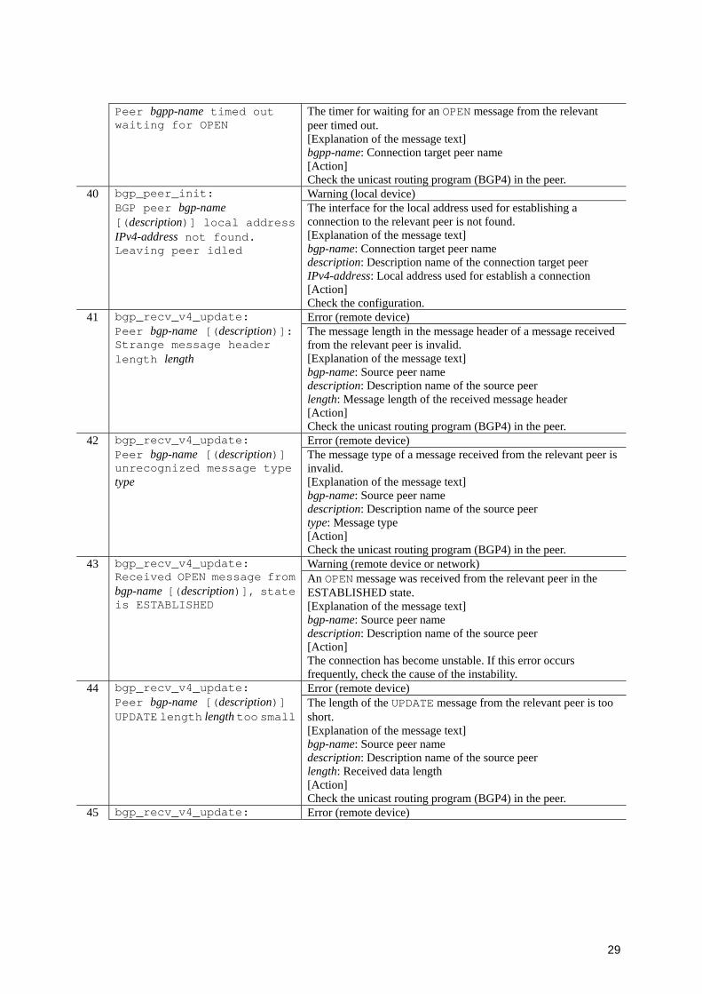
Copyright (c) 2005,2010, ALAXALA Networks Corporation. All rights reserved.
History of Amendments
[For Version 11.4]
Table Summary of amendments Location and title Changes
3.3.3 Event location = VLAN (Ring Protocol)
• Log messages related to multi-fault monitoring functionality have been added.
3.4.1 Event location = • Log messages related to IPv6 DHCP relays have been added. • Log messages related to power saving functionality have been
added. • Log messages related to DHCP snooping have been added.
3.5.2 Event location = ULR • Log messages related to automatic preemption functionality have been added.
In addition to the above changes, minor editorial corrections have been made.
[For Version 11.2]
Table Summary of amendments Item Changes
Event location = VLAN (Ring Protocol) • Log messages related to path switch-back suppression functionality were added.
Event location = SOFTWARE • Log messages related to VRRP tracking functionality were added. Event location = ULR • This subsection was added.
[For Version 11.1]
Table Summary of amendments Item Changes
RIP • Log messages related to authentication were added. Event location = VLAN (CFM) • This subsection was added.
[For Version 11.0]
Table Summary of amendments Item Changes
Event location = VLAN • Log messages for clearing the MAC address table by receiving ordinary Flush Request frames were added.
Event location = SOFTWARE • Log messages related to setting the maximum number of multi paths were added.
[For Version 10.8]
Table Summary of amendments Item Changes
Event location = VLAN • The log message for message ID 25100031 was deleted. Event location = VLAN (GSRP) • Log messages for when the automatic master wait time elapsed
were added. Event location = SOFTWARE • The descriptions of log messages related to IEEE802.1X were
changed. • The descriptions of log messages related to Web authentication
were changed. • The descriptions of log messages related to MAC-based
authentication were changed. • Log messages related to packet queuing addressed to CPU were
added. Event location = SOFTWARE (VLAN • The descriptions of log messages related to authentication VLAN
authentication) were changed.
[For Version 10.7]
Table Summary of amendments Item Changes
BGP4 • Log messages related to BGP4 were added. BGP4+ • Log messages related to BGP4+ were added. PIM-SM • Log messages related to registering packets were changed. Event location = VLAN • The descriptions related to running the ring protocol and multiple
spanning tree together were changed. Event location = VLAN (GSRP) • The descriptions related to running the ring protocol and GSRP
together were changed. Event location = VLAN (detecting L2 loops)
• This subsection was added.
Event location = SOFTWARE • Log messages related to detecting L2 loops were added.
[For Version 10.6]
Table Summary of amendments Item Changes
Event location = SOFTWARE • Log messages related to MAC-based authentication were added.
[For Version 10.4]
Table Summary of amendments Item Changes
Event location = VLAN (Ring Protocol)
• This subsection was added.
Event location = SOFTWARE • Log messages related to sFlow statistics were added. • Log messages related to ring protocol were added.
[For Version 10.3]
Table Summary of amendments Item Changes
Event location = ACCESS • Log messages related to local command authorization were added. • Part of additional information of upper four digits for
RADIUS/TACACS+ was changed. Event location = VLAN • Log messages when using the root guard functionality and receiving
BPDU were added. Event location = SOFTWARE • Log messages related to IEEE802.3ah/UDLD were added.
• Log messages related to multi-cast were added. • Log messages related to Web authentication were added.
Event location = SOFTWARE (authentication VLAN)
• Log messages related to authentication VLAN were added.
Event location = PORT • Log messages related to IEEE802.3ah/UDLD were added. • Log messages related to detecting unidirectional link failures were
added.
[For Version 10.2]
Table Summary of amendments Item Changes
Log code information • The identifier of the event location was changed from LINE to PORT.
OSPF • A new log message (item number 12) was added. BGP4 • New log messages (item numbers 89 to 95 and 100 to 102) were
added. OSPFv3 • A new log message (number 12) was added.

BGP4+ • New log messages (item numbers 86 to 92 and 97 to 99) were added.Event location = CONFIG • The message identifier for item numbers 1 to 3 were changed.
• A new log message (item number 4) was added. Event location = VLAN • The log message for message identifier 20110030 was deleted.
• New log messages (item numbers 37, 38, 45, and 46) were added. • In the message, NIF was changed to NIF No. and Line was
changed to Port No.. Event location = MAC • In the message, NIF was changed to NIF No. and Line was
changed to Port No.. Event location = SOFTWARE • Log messages for message identifiers 00005007 and 00005017 were
deleted. • New log messages (item numbers 13, 14, 15, 42, 43, 44, 69, 93, 94,
116, and 117) were added. • The message identifier for item numbers 85 and 113 were changed.
Event location = PORT • The identifier of the event location was changed from LINE to PORT.
• New log messages (item numbers 2, 4, and 22 to 30) were added. • Log messages for item numbers 1, 3, 6 to 17, 19 to 21, and 31 to 33
were changed. Event location = PS • New log messages (item numbers 1, 3, and 6) were added. Event location = EQUIPMENT • A new log message (item number 1) was added. Event location = FAN • This subsection was added.

I
Preface
Applicable products and software versions
This manual applies to the models of the AX3600S series of switches. The manual describes the functions of
software version 11.4 for AX3600S that are supported by the OS-L3L and OS-L3A software and optional
licenses.
Before you operate the equipment, carefully read the manual and make sure that you understand all instructions
and notes. After reading the manual, keep it in a convenient place for easy reference.
Unless otherwise noted, this manual describes the functions applicable to both AX3640S and AX3630S switches
and to both OS-L3L and OS-L3A. Those functions specific to either AX3640S or AX3630S switches and to
OS-L3A are indicated as follows:
[AX3640S]:
The description applies to AX3640S switches.
[AX3630S]:
The description applies to AX3630S switches.
[OS-L3A]:
The description applies to the optional license OS-L3A.
The functions supported by optional licenses are indicated as follows:
[OP-DH6R]:
The description applies to the optional license OP-DH6R.
[OP-OTP]:
The description applies to the optional license OP-OTP.
[OP-VAA]:
The description applies to the optional license OP-VAA.
Corrections to the manual
Corrections to this manual are contained in the Release Notes and Manual Corrections that might come with the
software.
Intended readers
This manual is intended for system administrators who configure and operate a network system that uses
AX3600S series switches.
Readers must have an understanding of the following:
The basics of network system management
II
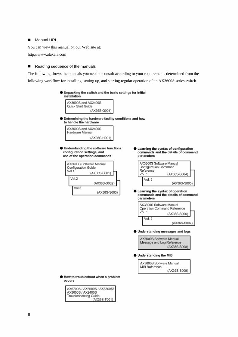
Manual URL
You can view this manual on our Web site at:
http://www.alaxala.com
Reading sequence of the manuals
The following shows the manuals you need to consult according to your requirements determined from the
following workflow for installing, setting up, and starting regular operation of an AX3600S series switch.
III
Abbreviations used in the manual AC Alternating Current ACK ACKnowledge ADSL Asymmetric Digital Subscriber Line ALG Application Level Gateway ANSI American National Standards Institute ARP Address Resolution Protocol AS Autonomous System AUX Auxiliary BGP Border Gateway Protocol BGP4 Border Gateway Protocol - version 4 BGP4+ Multiprotocol Extensions for Border Gateway Protocol - version 4 bit/s bits per second (can also appear as bps) BPDU Bridge Protocol Data Unit BRI Basic Rate Interface CC Continuity Check CDP Cisco Discovery Protocol CFM Connectivity Fault Management CIDR Classless Inter-Domain Routing CIR Committed Information Rate CIST Common and Internal Spanning Tree CLNP ConnectionLess Network Protocol CLNS ConnectionLess Network System CONS Connection Oriented Network System CRC Cyclic Redundancy Check CSMA/CD Carrier Sense Multiple Access with Collision Detection CSNP Complete Sequence Numbers PDU CST Common Spanning Tree DA Destination Address DC Direct Current DCE Data Circuit terminating Equipment DHCP Dynamic Host Configuration Protocol DIS Draft International Standard/Designated Intermediate System DNS Domain Name System DR Designated Router DSAP Destination Service Access Point DSCP Differentiated Services Code Point DTE Data Terminal Equipment DVMRP Distance Vector Multicast Routing Protocol E-Mail Electronic Mail EAP Extensible Authentication Protocol EAPOL EAP Over LAN EFM Ethernet in the First Mile ES End System FAN Fan Unit FCS Frame Check Sequence FDB Filtering DataBase FQDN Fully Qualified Domain Name FTTH Fiber To The Home GBIC GigaBit Interface Converter GSRP Gigabit Switch Redundancy Protocol HMAC Keyed-Hashing for Message Authentication IANA Internet Assigned Numbers Authority ICMP Internet Control Message Protocol ICMPv6 Internet Control Message Protocol version 6 ID Identifier IEC International Electrotechnical Commission
IV
IEEE Institute of Electrical and Electronics Engineers, Inc. IETF the Internet Engineering Task Force IGMP Internet Group Management Protocol IP Internet Protocol IPCP IP Control Protocol IPv4 Internet Protocol version 4 IPv6 Internet Protocol version 6 IPV6CP IP Version 6 Control Protocol IPX Internetwork Packet Exchange ISO International Organization for Standardization ISP Internet Service Provider IST Internal Spanning Tree L2LD Layer 2 Loop Detection LAN Local Area Network LCP Link Control Protocol LED Light Emitting Diode LLC Logical Link Control LLDP Link Layer Discovery Protocol LLQ+3WFQ Low Latency Queueing + 3 Weighted Fair Queueing LSP Label Switched Path LSP Link State PDU LSR Label Switched Router MA Maintenance Association MAC Media Access Control MC Memory Card MD5 Message Digest 5 MDI Medium Dependent Interface MDI-X Medium Dependent Interface crossover MEP Maintenance association End Point MIB Management Information Base MIP Maintenance domain Intermediate Point MRU Maximum Receive Unit MSTI Multiple Spanning Tree Instance MSTP Multiple Spanning Tree Protocol MTU Maximum Transfer Unit NAK Not AcKnowledge NAS Network Access Server NAT Network Address Translation NCP Network Control Protocol NDP Neighbor Discovery Protocol NET Network Entity Title NLA ID Next-Level Aggregation Identifier NPDU Network Protocol Data Unit NSAP Network Service Access Point NSSA Not So Stubby Area NTP Network Time Protocol OADP Octpower Auto Discovery Protocol OAM Operations, Administration, and Maintenance OSPF Open Shortest Path First OUI Organizationally Unique Identifier PAD PADding PAE Port Access Entity PC Personal Computer PCI Protocol Control Information PDU Protocol Data Unit PICS Protocol Implementation Conformance Statement PID Protocol IDentifier PIM Protocol Independent Multicast

V
PIM-DM Protocol Independent Multicast-Dense Mode PIM-SM Protocol Independent Multicast-Sparse Mode PIM-SSM Protocol Independent Multicast-Source Specific Multicast PoE Power over Ethernet PRI Primary Rate Interface PS Power Supply PSNP Partial Sequence Numbers PDU QoS Quality of Service RA Router Advertisement RADIUS Remote Authentication Dial In User Service RDI Remote Defect Indication REJ REJect RFC Request For Comments RIP Routing Information Protocol RIPng Routing Information Protocol next generation RMON Remote Network Monitoring MIB RPF Reverse Path Forwarding RQ ReQuest RSTP Rapid Spanning Tree Protocol SA Source Address SD Secure Digital SDH Synchronous Digital Hierarchy SDU Service Data Unit SEL NSAP SELector SFD Start Frame Delimiter SFP Small Form factor Pluggable SMTP Simple Mail Transfer Protocol SNAP Sub-Network Access Protocol SNMP Simple Network Management Protocol SNP Sequence Numbers PDU SNPA Subnetwork Point of Attachment SPF Shortest Path First SSAP Source Service Access Point STP Spanning Tree Protocol TA Terminal Adapter TACACS+ Terminal Access Controller Access Control System Plus TCP/IP Transmission Control Protocol/Internet Protocol TLA ID Top-Level Aggregation Identifier TLV Type, Length, and Value TOS Type Of Service TPID Tag Protocol Identifier TTL Time To Live UDLD Uni-Directional Link Detection UDP User Datagram Protocol UPC Usage Parameter Control UPC-RED Usage Parameter Control - Random Early Detection VAA VLAN Access Agent VLAN Virtual LAN VRRP Virtual Router Redundancy Protocol WAN Wide Area Network WDM Wavelength Division Multiplexing WFQ Weighted Fair Queueing WRED Weighted Random Early Detection WS Work Station WWW World-Wide Web XFP 10 gigabit small Form factor Pluggable

VI
Conventions such as KB (kilobytes)
This manual uses the following conventions: 1 KB (kilobyte) is 1,024 bytes. 1 MB (megabyte) is 1,0242 bytes. 1
GB (gigabyte) is 1,0243 bytes. 1 TB (terabyte) is 1,0244 bytes.

i
Contents 1. Operation Messages and Logs ...........................................................................................1
1.1 Checking operation messages ...........................................................................................................2 1.1.1 Message types.................................................................................................................................. 2 1.1.2 Contents of operation messages....................................................................................................... 2 1.1.3 Format of operation messages ......................................................................................................... 3 1.1.4 Outputting operation messages........................................................................................................ 3
1.2 Checking the log ...............................................................................................................................5 1.2.1 Log types ......................................................................................................................................... 5 1.2.2 Log contents .................................................................................................................................... 5 1.2.3 Format of operation logs.................................................................................................................. 6 1.2.4 Format of reference logs.................................................................................................................. 7 1.2.5 Code information for logs................................................................................................................ 8 1.2.6 Automatically saving and referencing logs.................................................................................... 10
2. Routing Event Information..............................................................................................13 2.1 IPv4 routing protocol information (RTM) ......................................................................................14
2.1.1 RIP................................................................................................................................................. 14 2.1.2 OSPF [OS-L3A]............................................................................................................................ 18 2.1.3 BGP4 [OS-L3A]............................................................................................................................ 22 2.1.4 Common to IPv4 unicast routing protocols ................................................................................... 41
2.2 IPv6 routing protocol information (RTM) ......................................................................................43 2.2.1 RIPng............................................................................................................................................. 43 2.2.2 OSPFv3 [OS-L3A]........................................................................................................................ 45 2.2.3 BGP4+ [OS-L3A] ......................................................................................................................... 48 2.2.4 Common to IPv6 unicast routing protocols ................................................................................... 66
2.3 IPv6 routing information (RTM) ....................................................................................................67 2.3.1 RA ................................................................................................................................................. 67
2.4 IPv4 multicast routing information (MRP).....................................................................................69 2.4.1 PIM-SM......................................................................................................................................... 69
2.5 IPv6 multicast routing information (MR6) .....................................................................................74 2.5.1 IPv6 PIM-SM ................................................................................................................................ 74
3. Device Failure and Event Information ...........................................................................81 3.1 Configuration ..................................................................................................................................82
3.1.1 Event location = CONFIG............................................................................................................. 82 3.2 Access .............................................................................................................................................84
3.2.1 Event location = ACCESS............................................................................................................. 84 3.3 Protocol...........................................................................................................................................90
3.3.1 Event location = IP ........................................................................................................................ 90 3.3.2 Event location = VLAN................................................................................................................. 94 3.3.3 Event location = VLAN (Ring Protocol) ..................................................................................... 106 3.3.4 Event location = VLAN (GSRP) ................................................................................................. 108 3.3.5 Event location = VLAN (L2 loop detection) ............................................................................... 112 3.3.6 Event location = VLAN (CFM)................................................................................................... 114 3.3.7 Event location = MAC................................................................................................................. 116
3.4 Switch parts...................................................................................................................................121 3.4.1 Event location = SOFTWARE .................................................................................................... 121 3.4.2 Event location = SOFTWARE (Authentication VLAN)【OP-VAA】 ....................................... 151
3.5 PORT ............................................................................................................................................154 3.5.1 Event location = PORT................................................................................................................ 154 3.5.2 Event location = ULR.................................................................................................................. 159
3.6 Option Structure............................................................................................................................166 3.6.1 Event location = PS ..................................................................................................................... 166 3.6.2 Event location = EQUIPMENT................................................................................................... 167 3.6.3 Event location = FAN.................................................................................................................. 170

ii
1
1. Operation Messages and Logs
This chapter explains how to use the failed part, operation messages, and logs to identify the
location of errors that have occurred.
2
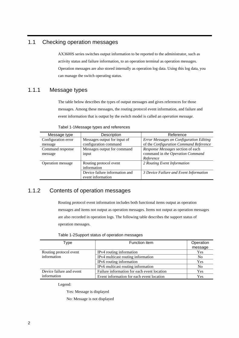
1.1 Checking operation messages
AX3600S series switches output information to be reported to the administrator, such as
activity status and failure information, to an operation terminal as operation messages.
Operation messages are also stored internally as operation log data. Using this log data, you
can manage the switch operating status.
1.1.1 Message types
The table below describes the types of output messages and gives references for those
messages. Among these messages, the routing protocol event information, and failure and
event information that is output by the switch model is called an operation message.
Tabel 1-1Message types and references
Message type Description Reference Configuration error message
Messages output for input of configuration command
Error Messages on Configuration Editing of the Configuration Command Reference
Command response message
Messages output for command input
Response Messages section of each command in the Operation Command Reference
Operation message Routing protocol event information
2 Routing Event Information
Device failure information and event information
3 Device Failure and Event Information
1.1.2 Contents of operation messages
Routing protocol event information includes both functional items output as operation
messages and items not output as operation messages. Items not output as operation messages
are also recorded in operation logs. The following table describes the support status of
operation messages.
Table 1-2Support status of operation messages
Type Function item Operation message
IPv4 routing information Yes IPv4 multicast routing information No IPv6 routing information Yes
Routing protocol event information
IPv6 multicast routing information No Failure information for each event location Yes Device failure and event
information Event information for each event location Yes
Legend:
Yes: Message is displayed
No: Message is not displayed
3
1.1.3 Format of operation messages
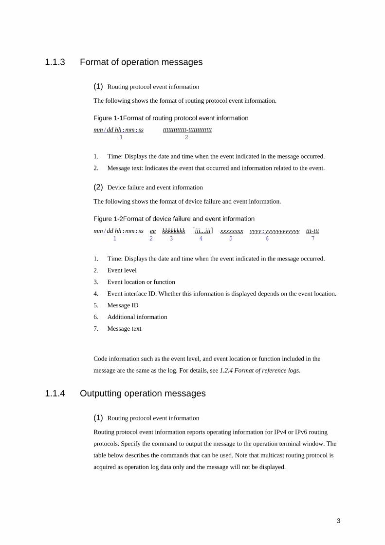
(1) Routing protocol event information
The following shows the format of routing protocol event information.
Figure 1-1Format of routing protocol event information
mm/dd hh:mm:ss ttttttttttttt-ttttttttttttt 1 2
1. Time: Displays the date and time when the event indicated in the message occurred.
2. Message text: Indicates the event that occurred and information related to the event.
(2) Device failure and event information
The following shows the format of device failure and event information.
Figure 1-2Format of device failure and event information
mm/dd hh:mm:ss ee kkkkkkkk [iii...iii] xxxxxxxx yyyy:yyyyyyyyyyyy ttt-ttt 1 2 3 4 5 6 7
1. Time: Displays the date and time when the event indicated in the message occurred.
2. Event level
3. Event location or function
4. Event interface ID. Whether this information is displayed depends on the event location.
5. Message ID
6. Additional information
7. Message text
Code information such as the event level, and event location or function included in the
message are the same as the log. For details, see 1.2.4 Format of reference logs.
1.1.4 Outputting operation messages
(1) Routing protocol event information
Routing protocol event information reports operating information for IPv4 or IPv6 routing
protocols. Specify the command to output the message to the operation terminal window. The
table below describes the commands that can be used. Note that multicast routing protocol is
acquired as operation log data only and the message will not be displayed.
4
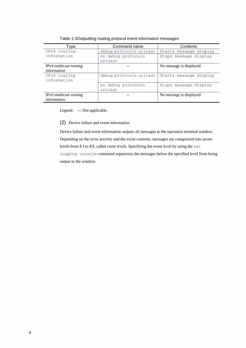
Table 1-3Outputting routing protocol event information messages
Type Command name Contents debug protocols unicast Starts message display IPv4 routing
information no debug protocols unicast
Stops message display
IPv4 multicast routing information
-- No message is displayed
IPv6 routing information
debug protocols unicast Starts message display
no debug protocols unicast
Stops message display
IPv6 multicast routing information
-- No message is displayed
Legend: --: Not applicable.
(2) Device failure and event information
Device failure and event information outputs all messages to the operation terminal window.
Depending on the error severity and the event contents, messages are categorized into seven
levels from E3 to E9, called event levels. Specifying the event level by using the set
logging console command suppresses the messages below the specified level from being
output to the window.
5
1.2 Checking the log
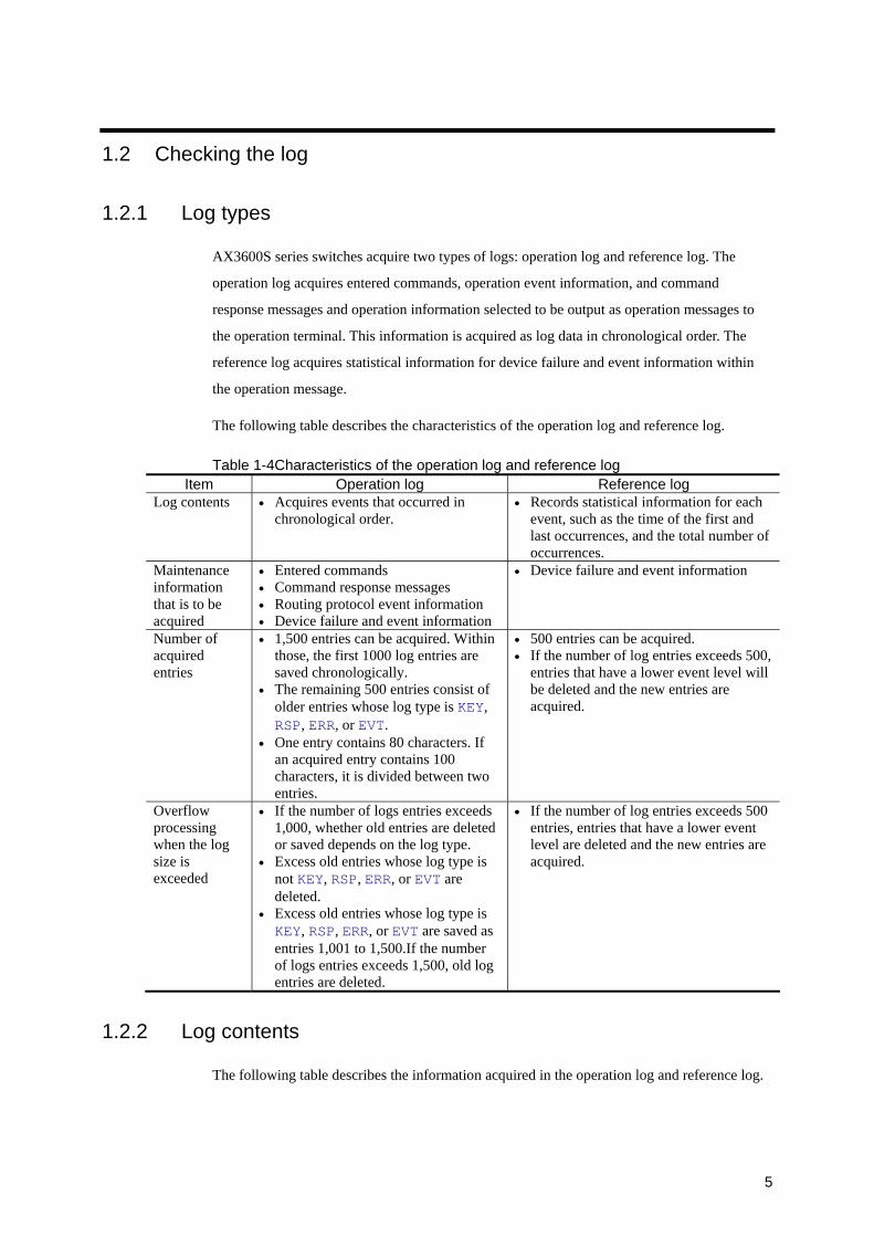
1.2.1 Log types
AX3600S series switches acquire two types of logs: operation log and reference log. The
operation log acquires entered commands, operation event information, and command
response messages and operation information selected to be output as operation messages to
the operation terminal. This information is acquired as log data in chronological order. The
reference log acquires statistical information for device failure and event information within
the operation message.
The following table describes the characteristics of the operation log and reference log.
Table 1-4Characteristics of the operation log and reference logItem Operation log Reference log
Log contents • Acquires events that occurred in chronological order.
• Records statistical information for each event, such as the time of the first and last occurrences, and the total number of occurrences.
Maintenance information that is to be acquired
• Entered commands • Command response messages • Routing protocol event information • Device failure and event information
• Device failure and event information
Number of acquired entries
• 1,500 entries can be acquired. Within those, the first 1000 log entries are saved chronologically.
• The remaining 500 entries consist of older entries whose log type is KEY, RSP, ERR, or EVT.
• One entry contains 80 characters. If an acquired entry contains 100 characters, it is divided between two entries.
• 500 entries can be acquired. • If the number of log entries exceeds 500,
entries that have a lower event level will be deleted and the new entries are acquired.
Overflow processing when the log size is exceeded
• If the number of logs entries exceeds 1,000, whether old entries are deleted or saved depends on the log type.
• Excess old entries whose log type is not KEY, RSP, ERR, or EVT are deleted.
• Excess old entries whose log type is KEY, RSP, ERR, or EVT are saved as entries 1,001 to 1,500.If the number of logs entries exceeds 1,500, old log entries are deleted.
• If the number of log entries exceeds 500 entries, entries that have a lower event level are deleted and the new entries are acquired.
1.2.2 Log contents
The following table describes the information acquired in the operation log and reference log.

6
Table 1-5Information acquired in the operation log and reference log
Category Contents Operation log
Reference log
See
Entered commands
Commands entered from the operation terminal by operators.
Yes No --
Command response messages
Messages output by switches to respond to entered commands.
Yes No Response Messages section of each command in the Operation Command Reference
IPv4 routing protocol information
Yes No
IPv4 multicast routing information
Yes No
IPv6 routing protocol information
Yes No
Routing protocol event information
IPv6 multicast routing information
Yes No
2 Routing Event Information
Error information per event location of the switch.
Yes Yes Device failure and event information
Error information per event location of the switch.
Yes Yes
3 Device Failure and Event Information
Legend:
Yes: Messages are displayed or log data is acquired.
No: Messages are not displayed and log data is acquired.
--: Not applicable.
1.2.3 Format of operation logs
Messages that are in operation are saved within the device. When storing logs, logs are
formatted with a log type given to the information that is output as operation messages to the
window.
(1) Routing protocol event information
The following describes the formats for entered commands, command response messages, and
routing protocol event information.
Figure 1-3Format of entered commands, command response messages, and routing protocol event information
kkk mm/dd hh:mm:ss ttttttttttttt-ttttttttttttt 1 2 3
1. Log type: A 3-letter identification code applied for each provided functionality.
• KEY: Operational information selected by entered commands.
• RSP: Event information related to command response messages.
7
• RTM, MRP, or MR6: Routing protocol event information
2. Time: Date and time that the log entry was acquired.
3. Message text
(2) Device failure and event information
The following shows the format of device failure and event information.
Figure 1-4Format of device failure and event information
kkk mm/dd hh:mm:ss ee kkkkkkkk [iii...iii] xxxxxxxx yyyy:yyyyyyyyyyyy 1 2 3 4 5 6 7 ttt-ttt 8
1. Log type: A 3-letter identification code applied for each provided functionality.
• ERR: Error information for a switch event location
• EVT: Event information for a switch event location
2. Time: Date and time that the event occurred.
3. Event level
4. Event location or function
5. Event interface ID. Whether this information is displayed depends on the event location.
6. Message ID
7. Additional information
8. Message text
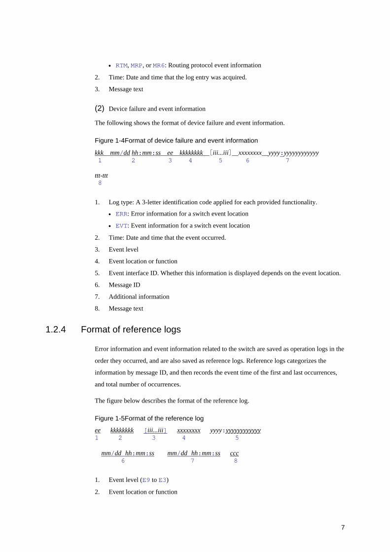
1.2.4 Format of reference logs
Error information and event information related to the switch are saved as operation logs in the
order they occurred, and are also saved as reference logs. Reference logs categorizes the
information by message ID, and then records the event time of the first and last occurrences,
and total number of occurrences.
The figure below describes the format of the reference log.
Figure 1-5Format of the reference log
ee kkkkkkkk [iii...iii] xxxxxxxx yyyy:yyyyyyyyyyyy 1 2 3 4 5 mm/dd hh:mm:ss mm/dd hh:mm:ss ccc 6 7 8
1. Event level (E9 to E3)
2. Event location or function
8
3. Event interface ID. Whether this information is displayed depends on the event location.
4. Message ID
5. Additional information
6. Occurrence date and time of the last applicable error.
7. Occurrence date and time of the first applicable error.
8. Number of occurrences of the applicable error.
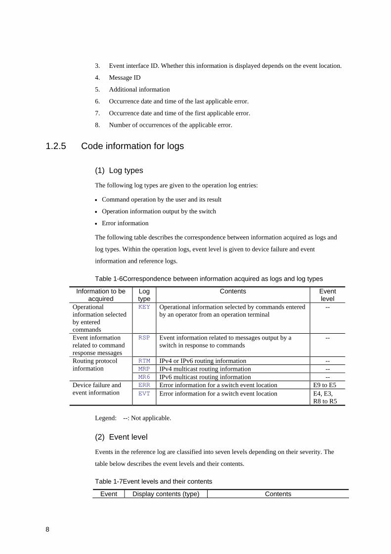
1.2.5 Code information for logs
(1) Log types
The following log types are given to the operation log entries:
• Command operation by the user and its result
• Operation information output by the switch
• Error information
The following table describes the correspondence between information acquired as logs and
log types. Within the operation logs, event level is given to device failure and event
information and reference logs.
Table 1-6Correspondence between information acquired as logs and log types
Information to be acquired
Log type
Contents Event level
Operational information selected by entered commands
KEY Operational information selected by commands entered by an operator from an operation terminal
--
Event information related to command response messages
RSP Event information related to messages output by a switch in response to commands
--
RTM IPv4 or IPv6 routing information -- MRP IPv4 multicast routing information --
Routing protocol information
MR6 IPv6 multicast routing information -- ERR Error information for a switch event location E9 to E5 Device failure and
event information EVT Error information for a switch event location E4, E3, R8 to R5
Legend: --: Not applicable.
(2) Event level
Events in the reference log are classified into seven levels depending on their severity. The
table below describes the event levels and their contents.
Table 1-7Event levels and their contents
Event Display contents (type) Contents
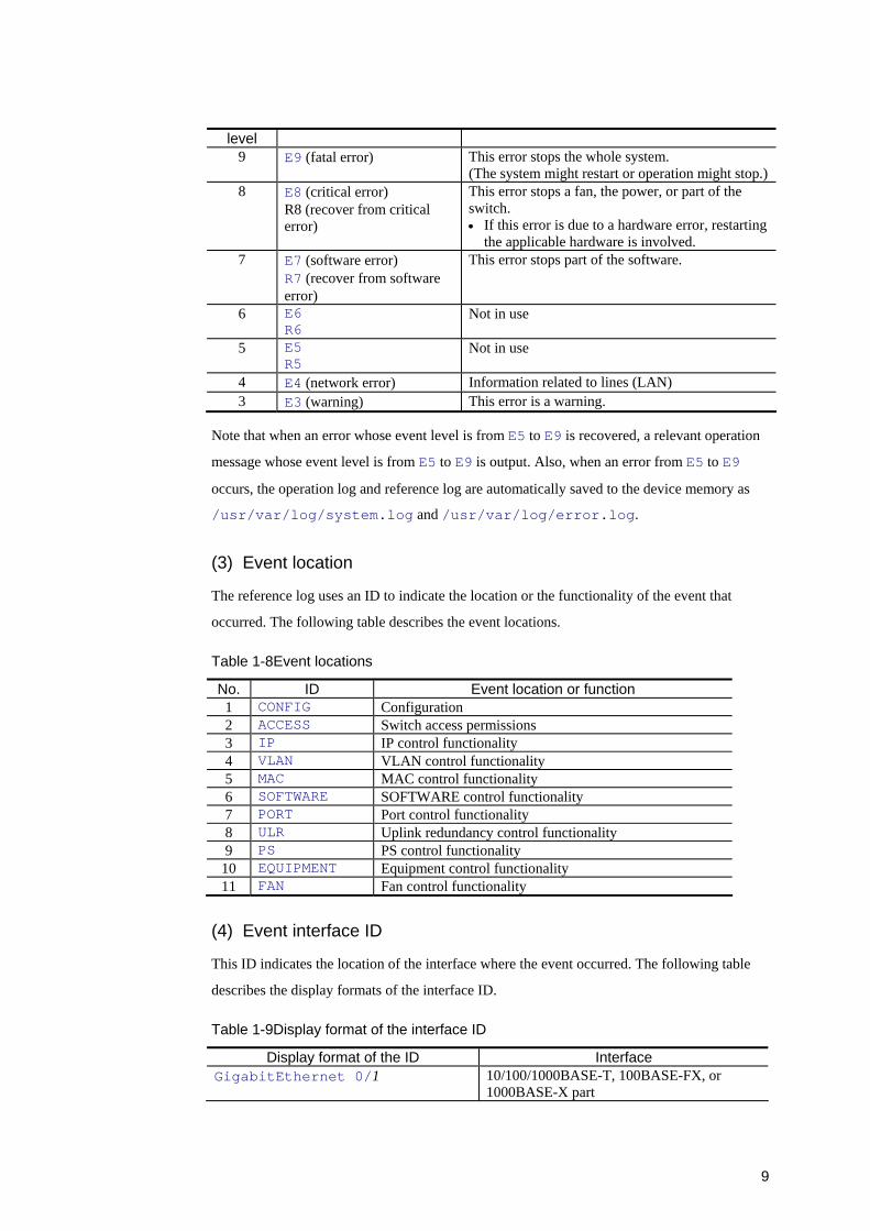
9
level 9 E9 (fatal error) This error stops the whole system.
(The system might restart or operation might stop.)8 E8 (critical error)
R8 (recover from critical error)
This error stops a fan, the power, or part of the switch. • If this error is due to a hardware error, restarting
the applicable hardware is involved. 7 E7 (software error)
R7 (recover from software error)
This error stops part of the software.
6 E6 R6
Not in use
5 E5 R5
Not in use
4 E4 (network error) Information related to lines (LAN) 3 E3 (warning) This error is a warning.
Note that when an error whose event level is from E5 to E9 is recovered, a relevant operation
message whose event level is from E5 to E9 is output. Also, when an error from E5 to E9
occurs, the operation log and reference log are automatically saved to the device memory as
/usr/var/log/system.log and /usr/var/log/error.log.
(3) Event location
The reference log uses an ID to indicate the location or the functionality of the event that
occurred. The following table describes the event locations.
Table 1-8Event locations
No. ID Event location or function 1 CONFIG Configuration 2 ACCESS Switch access permissions 3 IP IP control functionality 4 VLAN VLAN control functionality 5 MAC MAC control functionality 6 SOFTWARE SOFTWARE control functionality 7 PORT Port control functionality 8 ULR Uplink redundancy control functionality 9 PS PS control functionality
10 EQUIPMENT Equipment control functionality 11 FAN Fan control functionality
(4) Event interface ID
This ID indicates the location of the interface where the event occurred. The following table
describes the display formats of the interface ID.
Table 1-9Display format of the interface ID
Display format of the ID Interface GigabitEthernet 0/1 10/100/1000BASE-T, 100BASE-FX, or
1000BASE-X part
10
TenGigabitEthernet 0/1 10GBASE-R part
Legend:
1: Port number
(5) Message ID and additional information
This information contains a code that indicates the contents of the event that occurred. For
details, see 3 Device Failure and Event Information.
(6) Time of the first and last occurrences of the applicable event
This information indicates the time of the first and last occurrences of the applicable event.
(7) Number of occurrences of the applicable event
This information indicates the total number of occurrences of the applicable event if repeated.
The total is the number of event occurrences counting from the start of log acquisition to the
present. If the applicable event occurs 255 times or more, the number of occurrences will be
indicated as 255.
1.2.6 Automatically saving and referencing logs
(1) Saving logs automatically
This section describes the occasions when the operation logs and reference logs are
automatically saved to internal flash memory and the destination to which they are saved. Note
that if the configuration command no logging syslog-dump is set, logs are automatically
saved for occasion 1 only.
Occasions when logs are automatically saved:
1. When the AX3600S series switch is started
2. When a critical error with an event level from E5 to E9 occurs
3. When the device is restarted by using the reload operation command
4. When login or logout is performed
5. When the device is restarted accompanying ppupdate
6. When the device is restarted by pressing the reset switch
Table 1-10Destination of saved logs
Log type Location of internal memory Operation log Logs are saved to /usr/var/log/system.log Reference log Logs are saved to /usr/var/log/error.log

11
(2) Referencing logs and method for creating files
Operation logs and reference logs can be referenced by using the show logging command.
These logs can also be retrieved as files by specifying redirection when executing the show
logging command. If you want to output command output results to a file for a command
other than the show logging command, you also must specify redirection. The following
table describes the directory for storing the created files when redirection is specified for a
command.
Table 1-11Directory for storing the files
Item Stored directory Others Home directory for the user
/usr/home/user-account-name/ Stored in internal memory
Temporary directory /tmp/ When the switch stops due to power discontinuity or the reload command, stored files will be deleted.
The following shows an example of creating a backup of log information by executing the
show logging command.
Backing up the operation log in internal memory: > show logging > /usr/home/user-account-name/file-name >
(3) Acquiring logs from remote hosts
Logs can be acquired from remote hosts by using the syslog output functionality. However,
the syslog output functionality might lose log information due to reasons such as frame-loss.
For details on the syslog output functionality, see logging facility in the Configuration
Command Reference.
(4) Sending logs using the email functionality
Log information can be sent to remote hosts or to PCs by using the email functionality. This
functionality cannot receive emails. If a user replies to an email sent by this functionality, a
transmission error occurs.
For details on the email functionality, see logging email-from, or logging email-server in the
Configuration Command Reference.

12
13
2. Routing Event Information
This chapter explains the contents of routing event information. Routing protocol event
information reports the operating status of IPv4 and IPv6 routing protocols. To output
messages to the operation terminal screen, use commands. Note that multicast routing
protocols do not display messages but only collect them in operation logs.
14
2.1 IPv4 routing protocol information (RTM)
This section explains IPv4 routing protocol event information.
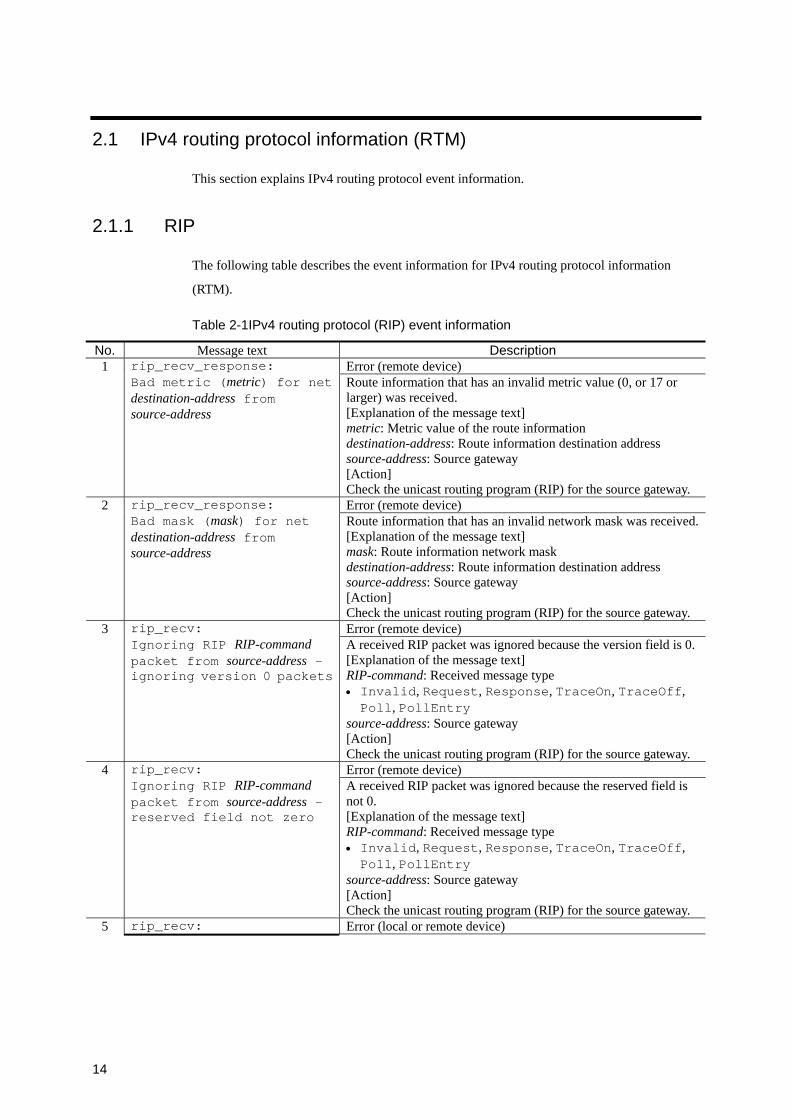
2.1.1 RIP
The following table describes the event information for IPv4 routing protocol information
(RTM).
Table 2-1IPv4 routing protocol (RIP) event information
No. Message text Description 1 Error (remote device)
rip_recv_response: Bad metric (metric) for net destination-address from source-address
Route information that has an invalid metric value (0, or 17 or larger) was received. [Explanation of the message text] metric: Metric value of the route information destination-address: Route information destination address source-address: Source gateway [Action] Check the unicast routing program (RIP) for the source gateway.
2 Error (remote device)
rip_recv_response: Bad mask (mask) for net destination-address from source-address
Route information that has an invalid network mask was received.[Explanation of the message text] mask: Route information network mask destination-address: Route information destination address source-address: Source gateway [Action] Check the unicast routing program (RIP) for the source gateway.
3 Error (remote device)
rip_recv: Ignoring RIP RIP-command packet from source-address - ignoring version 0 packets
A received RIP packet was ignored because the version field is 0.[Explanation of the message text] RIP-command: Received message type • Invalid, Request, Response, TraceOn, TraceOff, Poll, PollEntry
source-address: Source gateway [Action] Check the unicast routing program (RIP) for the source gateway.
4 Error (remote device)
rip_recv: Ignoring RIP RIP-command packet from source-address - reserved field not zero
A received RIP packet was ignored because the reserved field is not 0. [Explanation of the message text] RIP-command: Received message type • Invalid, Request, Response, TraceOn, TraceOff, Poll, PollEntry
source-address: Source gateway [Action] Check the unicast routing program (RIP) for the source gateway.
5 rip_recv: Error (local or remote device)
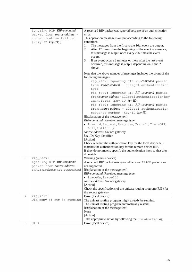
15
A received RIP packet was ignored because of an authentication error. This operation message is output according to the following conditions: 1. The messages from the first to the 16th event are output. 2. After 17 times from the beginning of the event occurrence,
this message is output once every 256 times the event occurs.
3. If an event occurs 3 minutes or more after the last event occurred, this message is output depending on 1 and 2 above.
Note that the above number of messages includes the count of the following messages:
rip_recv: Ignoring RIP RIP-command packet from source-address - illegal authentication type rip_recv: Ignoring RIP RIP-command packet from source-address - illegal authentication key identifier (Key-ID key-ID) rip_recv: Ignoring RIP RIP-command packet from source-address - illegal authentication sequence number (Key-ID key-ID)
Ignoring RIP RIP-command packet from source-address - authentication failure [(Key-ID key-ID)]
[Explanation of the message text] RIP-command: Received message type • Invalid, Request, Response, TraceOn, TraceOff, Poll, PollEntry
source-address: Source gateway key-ID: Key identifier [Action] Check whether the authentication key for the local device RIP matches the authentication key for the remote device RIP. If they do not match, specify the authentication keys so that they do match.
6 Warning (remote device)
rip_recv: Ignoring RIP RIP-command packet from source-address - TRACE packets not supported
A received RIP packet was ignored because TRACE packets are not supported. [Explanation of the message text] RIP-command: Received message type • TraceOn, TraceOff source-address: Source gateway [Action] Check the specifications of the unicast routing program (RIP) for the source gateway.
7 Error (local device)
rip_init: Old copy of rtm is running The unicast routing program might already be running.
The unicast routing program automatically restarts. [Explanation of the message text] None [Action] Take appropriate action by following the rtm aborted log.
8 RIP: Error (local device)

16
The total number of RIP targets is more than the maximum permitted
The total number of RIP targets (adjacent) exceeds the maximum number permitted. [Explanation of the message text] None [Action] Check, and if necessary, revise the RIP settings so that the maximum number of adjacent routers does not exceed the capacity limitations.
9 Error (remote device) A received RIP packet was ignored because the authentication
type of authentication information is invalid. This operation message is output according to the following conditions: 1. The messages from the first to the 16th event are output. 2. After 17 times from the beginning of the event occurrence,
this message is output once every 256 times the event occurs.
3. If an event occurs 3 minutes or more after the last event occurred, this message is output depending on 1 and 2 above.
Note that the above number of messages includes the count of the following messages:
rip_recv: Ignoring RIP RIP-command packet from source-address - authentication failure [(Key-ID key-ID)] rip_recv: Ignoring RIP RIP-command packet from source-address - illegal authentication key identifier (Key-ID key-ID) rip_recv: Ignoring RIP RIP-command packet from source-address - illegal authentication sequence number (Key-ID key-ID)
rip_recv: Ignoring RIP RIP-command packet from source-address - illegal authentication type
[Explanation of the message text] RIP-command: Received message type • Invalid, Request, Response, TraceOn, TraceOff, Poll, PollEntry
source-address: Source gateway [Action] Check the unicast routing program (RIP) for the source gateway.
10 rip_recv: Error (local or remote device)
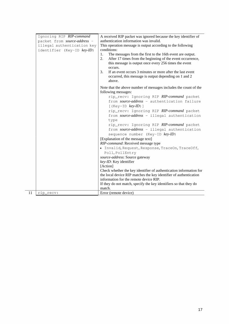
17
A received RIP packet was ignored because the key identifier of authentication information was invalid. This operation message is output according to the following conditions: 1. The messages from the first to the 16th event are output. 2. After 17 times from the beginning of the event occurrence,
this message is output once every 256 times the event occurs.
3. If an event occurs 3 minutes or more after the last event occurred, this message is output depending on 1 and 2 above.
Note that the above number of messages includes the count of the following messages:
rip_recv: Ignoring RIP RIP-command packet from source-address - authentication failure [(Key-ID key-ID)] rip_recv: Ignoring RIP RIP-command packet from source-address - illegal authentication type rip_recv: Ignoring RIP RIP-command packet from source-address - illegal authentication sequence number (Key-ID key-ID)
Ignoring RIP RIP-command packet from source-address - illegal authentication key identifier (Key-ID key-ID)
[Explanation of the message text] RIP-command: Received message type • Invalid, Request, Response, TraceOn, TraceOff, Poll, PollEntry
source-address: Source gateway key-ID: Key identifier [Action] Check whether the key identifier of authentication information for the local device RIP matches the key identifier of authentication information for the remote device RIP. If they do not match, specify the key identifiers so that they do match.
11 rip_recv: Error (remote device)
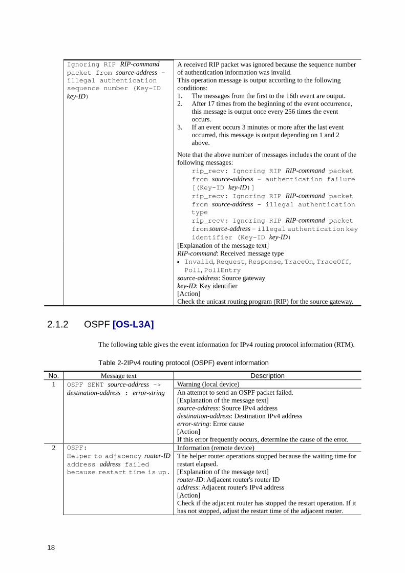
18
A received RIP packet was ignored because the sequence number of authentication information was invalid. This operation message is output according to the following conditions: 1. The messages from the first to the 16th event are output. 2. After 17 times from the beginning of the event occurrence,
this message is output once every 256 times the event occurs.
3. If an event occurs 3 minutes or more after the last event occurred, this message is output depending on 1 and 2 above.
Note that the above number of messages includes the count of the following messages:
rip_recv: Ignoring RIP RIP-command packet from source-address - authentication failure [(Key-ID key-ID)] rip_recv: Ignoring RIP RIP-command packet from source-address - illegal authentication type rip_recv: Ignoring RIP RIP-command packet from source-address - illegal authentication key identifier (Key-ID key-ID)
Ignoring RIP RIP-command packet from source-address - illegal authentication sequence number (Key-ID key-ID)
[Explanation of the message text] RIP-command: Received message type • Invalid, Request, Response, TraceOn, TraceOff, Poll, PollEntry
source-address: Source gateway key-ID: Key identifier [Action] Check the unicast routing program (RIP) for the source gateway.
2.1.2 OSPF [OS-L3A]
The following table gives the event information for IPv4 routing protocol information (RTM).
Table 2-2IPv4 routing protocol (OSPF) event information
No. Message text Description 1 Warning (local device)
OSPF SENT source-address -> destination-address : error-string An attempt to send an OSPF packet failed.
[Explanation of the message text] source-address: Source IPv4 address destination-address: Destination IPv4 address error-string: Error cause [Action] If this error frequently occurs, determine the cause of the error.
2 Information (remote device)
OSPF: Helper to adjacency router-IDaddress address failed because restart time is up.
The helper router operations stopped because the waiting time for restart elapsed. [Explanation of the message text] router-ID: Adjacent router's router ID address: Adjacent router's IPv4 address [Action] Check if the adjacent router has stopped the restart operation. If it has not stopped, adjust the restart time of the adjacent router.
19
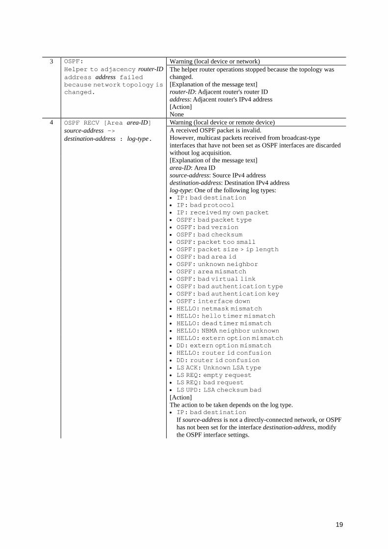
3 Warning (local device or network)
OSPF: Helper to adjacency router-IDaddress address failed because network topology is changed.
The helper router operations stopped because the topology was changed. [Explanation of the message text] router-ID: Adjacent router's router ID address: Adjacent router's IPv4 address [Action] None
4 Warning (local device or remote device)
OSPF RECV [Area area-ID] source-address -> destination-address : log-type.
A received OSPF packet is invalid. However, multicast packets received from broadcast-type interfaces that have not been set as OSPF interfaces are discarded without log acquisition.
[Explanation of the message text] area-ID: Area ID source-address: Source IPv4 address destination-address: Destination IPv4 address log-type: One of the following log types:
• IP: bad destination • IP: bad protocol • IP: received my own packet • OSPF: bad packet type • OSPF: bad version • OSPF: bad checksum • OSPF: packet too small • OSPF: packet size > ip length • OSPF: bad area id • OSPF: unknown neighbor
• OSPF: area mismatch • OSPF: bad virtual link • OSPF: bad authentication type • OSPF: bad authentication key • OSPF: interface down
• HELLO: netmask mismatch • HELLO: hello timer mismatch • HELLO: dead timer mismatch • HELLO: NBMA neighbor unknown
• HELLO: extern option mismatch • DD: extern option mismatch • HELLO: router id confusion • DD: router id confusion
• LS ACK: Unknown LSA type • LS REQ: empty request • LS REQ: bad request • LS UPD: LSA checksum bad
[Action] The action to be taken depends on the log type. • IP: bad destination
If source-address is not a directly-connected network, or OSPF has not been set for the interface destination-address, modify the OSPF interface settings.
20
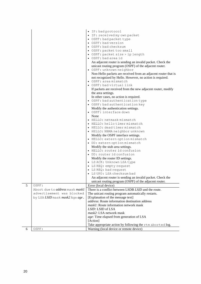
• IP: bad protocol • IP: received my own packet • OSPF: bad packet type • OSPF: bad version • OSPF: bad checksum • OSPF: packet too small • OSPF: packet size > ip length • OSPF: bad area id
An adjacent router is sending an invalid packet. Check the unicast routing program (OSPF) of the adjacent router.
• OSPF: unknown neighbor Non-Hello packets are received from an adjacent router that is not recognized by Hello. However, no action is required.
• OSPF: area mismatch • OSPF: bad virtual link
If packets are received from the new adjacent router, modify the area settings. In other cases, no action is required.
• OSPF: bad authentication type • OSPF: bad authentication key
Modify the authentication settings. • OSPF: interface down
None • HELLO: netmask mismatch
• HELLO: hello timer mismatch • HELLO: dead timer mismatch • HELLO: NBMA neighbor unknown
Modify the OSPF interface settings. • HELLO: extern option mismatch
• DD: extern option mismatch Modify the stub area settings.
• HELLO: router id confusion • DD: router id confusion
Modify the router ID settings. • LS ACK: Unknown LSA type
• LS REQ: empty request • LS REQ: bad request • LS UPD: LSA checksum bad
An adjacent router is sending an invalid packet. Check the unicast routing program (OSPF) of the adjacent router.
5 Error (local device)
OSPF: Abort due to address mask mask1advertisement was blocked by LSA LSID mask mask2 Age age.
There is a conflict between LSDB LSID and the route. The unicast routing program automatically restarts. [Explanation of the message text] address: Route information destination address mask1: Route information network mask LSID: LSID of LSA mask2: LSA network mask age: Time elapsed from generation of LSA [Action] Take appropriate action by following the rtm aborted log.
6 OSPF: Warning (local device or remote device)
21
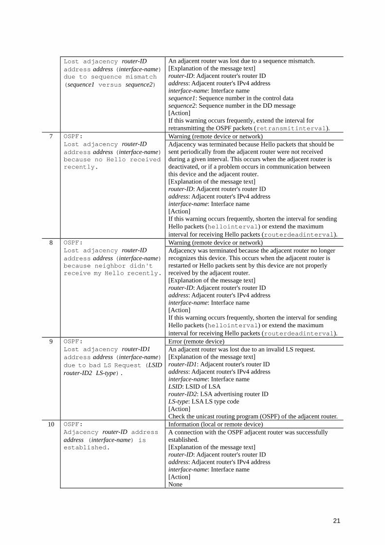
Lost adjacency router-ID address address (interface-name) due to sequence mismatch (sequence1 versus sequence2)
An adjacent router was lost due to a sequence mismatch. [Explanation of the message text] router-ID: Adjacent router's router ID address: Adjacent router's IPv4 address interface-name: Interface name sequence1: Sequence number in the control data sequence2: Sequence number in the DD message [Action] If this warning occurs frequently, extend the interval for retransmitting the OSPF packets (retransmitinterval).
7 Warning (remote device or network)
OSPF: Lost adjacency router-ID address address (interface-name) because no Hello received recently.
Adjacency was terminated because Hello packets that should be sent periodically from the adjacent router were not received during a given interval. This occurs when the adjacent router is deactivated, or if a problem occurs in communication between this device and the adjacent router. [Explanation of the message text] router-ID: Adjacent router's router ID address: Adjacent router's IPv4 address interface-name: Interface name [Action] If this warning occurs frequently, shorten the interval for sending Hello packets (hellointerval) or extend the maximum interval for receiving Hello packets (routerdeadinterval).
8 Warning (remote device or network)
OSPF: Lost adjacency router-ID address address (interface-name) because neighbor didn't receive my Hello recently.
Adjacency was terminated because the adjacent router no longer recognizes this device. This occurs when the adjacent router is restarted or Hello packets sent by this device are not properly received by the adjacent router. [Explanation of the message text] router-ID: Adjacent router's router ID address: Adjacent router's IPv4 address interface-name: Interface name [Action] If this warning occurs frequently, shorten the interval for sending Hello packets (hellointerval) or extend the maximum interval for receiving Hello packets (routerdeadinterval).
9 Error (remote device)
OSPF: Lost adjacency router-ID1 address address (interface-name) due to bad LS Request (LSIDrouter-ID2 LS-type).
An adjacent router was lost due to an invalid LS request. [Explanation of the message text] router-ID1: Adjacent router's router ID address: Adjacent router's IPv4 address interface-name: Interface name LSID: LSID of LSA router-ID2: LSA advertising router ID LS-type: LSA LS type code [Action] Check the unicast routing program (OSPF) of the adjacent router.
10 Information (local or remote device)
OSPF: Adjacency router-ID address address (interface-name) is established.
A connection with the OSPF adjacent router was successfully established. [Explanation of the message text] router-ID: Adjacent router's router ID address: Adjacent router's IPv4 address interface-name: Interface name [Action] None
22
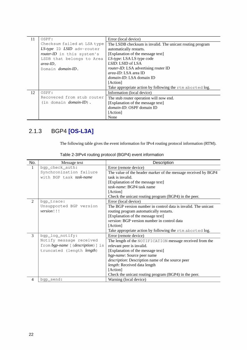
11 Error (local device)
OSPF: Checksum failed at LSA type LS-type ID LSID adv-router router-ID in this system's LSDB that belongs to Area area-ID, Domain domain-ID.
The LSDB checksum is invalid. The unicast routing program automatically restarts. [Explanation of the message text] LS-type: LSA LS type code LSID: LSID of LSA router-ID: LSA advertising router ID area-ID: LSA area ID domain-ID: LSA domain ID [Action] Take appropriate action by following the rtm aborted log.
12 Information (local device)
OSPF: Recovered from stub router (in domain domain-ID).
The stub router operation will now end. [Explanation of the message text] domain-ID: OSPF domain ID [Action] None
2.1.3 BGP4 [OS-L3A]
The following table gives the event information for IPv4 routing protocol information (RTM).
Table 2-3IPv4 routing protocol (BGP4) event information
No. Message text Description 1 Error (remote device)
bgp_check_auth: Synchronization failure with BGP task task-name
The value of the header marker of the message received by BGP4 task is invalid. [Explanation of the message text] task-name: BGP4 task name [Action] Check the unicast routing program (BGP4) in the peer.
2 Error (local device)
bgp_trace: Unsupported BGP version version!!!
The BGP version number in control data is invalid. The unicast routing program automatically restarts. [Explanation of the message text] version: BGP version number in control data [Action] Take appropriate action by following the rtm aborted log.
3 Error (remote device)
bgp_log_notify: Notify message received from bgp-name [(description)] is truncated (length length)
The length of the NOTIFICATION message received from the relevant peer is invalid. [Explanation of the message text] bgp-name: Source peer name description: Description name of the source peer length: Received data length [Action] Check the unicast routing program (BGP4) in the peer.
4 bgp_send: Warning (local device)
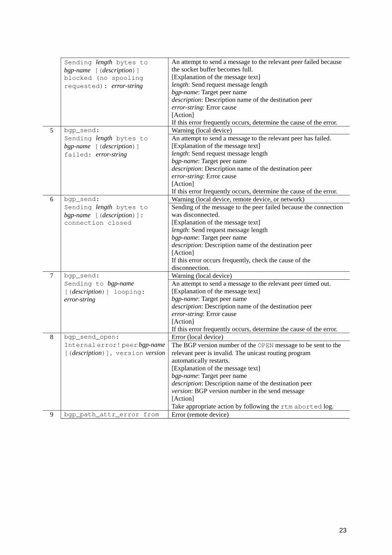
23
Sending length bytes to bgp-name [(description)] blocked (no spooling requested): error-string
An attempt to send a message to the relevant peer failed because the socket buffer becomes full. [Explanation of the message text] length: Send request message length bgp-name: Target peer name description: Description name of the destination peer error-string: Error cause [Action] If this error frequently occurs, determine the cause of the error.
5 Warning (local device)
bgp_send: Sending length bytes to bgp-name [(description)] failed: error-string
An attempt to send a message to the relevant peer has failed. [Explanation of the message text] length: Send request message length bgp-name: Target peer name description: Description name of the destination peer error-string: Error cause [Action] If this error frequently occurs, determine the cause of the error.
6 Warning (local device, remote device, or network)
bgp_send: Sending length bytes to bgp-name [(description)]: connection closed
Sending of the message to the peer failed because the connection was disconnected. [Explanation of the message text] length: Send request message length bgp-name: Target peer name description: Description name of the destination peer [Action] If this error occurs frequently, check the cause of the disconnection.
7 Warning (local device)
bgp_send: Sending to bgp-name [(description)] looping: error-string
An attempt to send a message to the relevant peer timed out. [Explanation of the message text] bgp-name: Target peer name description: Description name of the destination peer error-string: Error cause [Action] If this error frequently occurs, determine the cause of the error.
8 Error (local device)
bgp_send_open: Internal error! peer bgp-name[(description)], version version
The BGP version number of the OPEN message to be sent to the relevant peer is invalid. The unicast routing program automatically restarts. [Explanation of the message text] bgp-name: Target peer name description: Description name of the destination peer version: BGP version number in the send message [Action] Take appropriate action by following the rtm aborted log.
9 bgp_path_attr_error from Error (remote device)
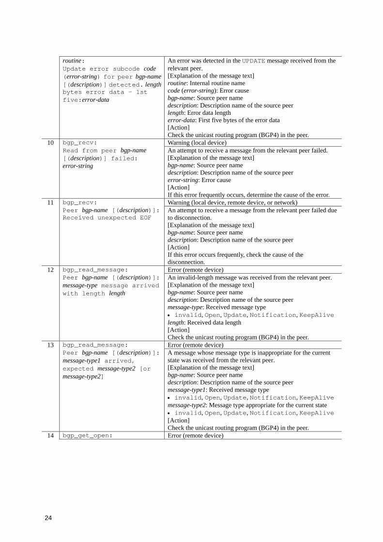
24
routine: Update error subcode code (error-string) for peer bgp-name[(description)] detected. lengthbytes error data - 1st five:error-data
An error was detected in the UPDATE message received from the relevant peer. [Explanation of the message text] routine: Internal routine name code (error-string): Error cause bgp-name: Source peer name description: Description name of the source peer length: Error data length error-data: First five bytes of the error data [Action] Check the unicast routing program (BGP4) in the peer.
10 Warning (local device)
bgp_recv: Read from peer bgp-name [(description)] failed: error-string
An attempt to receive a message from the relevant peer failed. [Explanation of the message text] bgp-name: Source peer name description: Description name of the source peer error-string: Error cause [Action] If this error frequently occurs, determine the cause of the error.
11 Warning (local device, remote device, or network)
bgp_recv: Peer bgp-name [(description)]: Received unexpected EOF
An attempt to receive a message from the relevant peer failed due to disconnection. [Explanation of the message text] bgp-name: Source peer name description: Description name of the source peer [Action] If this error occurs frequently, check the cause of the disconnection.
12 Error (remote device)
bgp_read_message: Peer bgp-name [(description)]: message-type message arrived with length length
An invalid-length message was received from the relevant peer. [Explanation of the message text] bgp-name: Source peer name description: Description name of the source peer message-type: Received message type • invalid, Open, Update, Notification, KeepAlive length: Received data length [Action] Check the unicast routing program (BGP4) in the peer.
13 Error (remote device)
bgp_read_message: Peer bgp-name [(description)]: message-type1 arrived, expected message-type2 [or message-type2]
A message whose message type is inappropriate for the current state was received from the relevant peer. [Explanation of the message text] bgp-name: Source peer name description: Description name of the source peer message-type1: Received message type • invalid, Open, Update, Notification, KeepAlive message-type2: Message type appropriate for the current state • invalid, Open, Update, Notification, KeepAlive [Action] Check the unicast routing program (BGP4) in the peer.
14 bgp_get_open: Error (remote device)

25
Peer bgp-name [(description)]: received short version version message (length octets)
An invalid-length OPEN message was received from the relevant peer. [Explanation of the message text] bgp-name: Source peer name description: Description name of the source peer version: BGP version number in the received message length: Received data length [Action] Check the unicast routing program (BGP4) in the peer.
15 Warning (remote device)
bgp_get_open: Received unsupported version version message from peer bgp-name [(description)]
An OPEN message that has an unsupported BGP version was received from a peer. [Explanation of the message text] version: BGP version number of received messages bgp-name: Source peer name description: Description name of the source peer [Action] Make sure that the peer supports BGP version 4.
16 Error (remote device)
bgp_get_open: Peer bgp-name [(description)]: hold time too small (holdtime)
An OPEN message whose hold time is less than three seconds was received from the relevant peer. [Explanation of the message text] bgp-name: Source peer name description: Description name of the source peer holdtime: Hold time in the received message [Action] Check the peer configuration.
17 Error (remote device)
bgp_get_open: Peer bgp-name [(description)]: invalid BGP identifier router-ID
An OPEN message that has an invalid BGP identifier was received from the relevant peer. [Explanation of the message text] bgp-name: Source peer name description: Description name of the source peer router-ID: BGP identifier in the received message [Action] Check the unicast routing program (BGP4) in the peer.
18 Error (remote device)
bgp_get_open: Peer bgp-name [(description)]: Unsupported optional parameter option
An OPEN message that contains an invalid option code was received from the relevant peer. [Explanation of the message text] bgp-name: Source peer name description: Description name of the source peer option: Option code in the received message [Action] Check the unicast routing program (BGP4) in the peer.
19 Warning (local device or remote device)
bgp_recv_open: Peer bgp-name [(description)] claims AS as1, as2 configured
An OPEN message that has a different AS number than the configured AS number was received from the relevant peer. [Explanation of the message text] bgp-name: Source peer name description: Description name of the source peer as1: AS number of the received message as2: AS number of the peer in the configuration [Action] Check the configuration.
20 bgp_recv_open: Warning (remote device)
26
Peer bgp-name [(description)] accepted mismatched versions: peer version1 this system version2
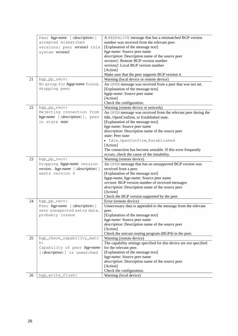
A KEEPALIVE message that has a mismatched BGP version number was received from the relevant peer. [Explanation of the message text] bgp-name: Source peer name description: Description name of the source peer version1: Remote BGP version number version2: Local BGP version number [Action] Make sure that the peer supports BGP version 4.
21 Warning (local device or remote device)
bgp_pp_recv: No group for bgpp-name found, dropping peer
An OPEN message was received from a peer that was not set. [Explanation of the message text] bgpp-name: Source peer name [Action] Check the configuration.
22 Warning (remote device or network)
bgp_pp_recv: Rejecting connection from bgp-name [(description)], peer in state state
An OPEN message was received from the relevant peer during the Idle, OpenConfirm, or Established state. [Explanation of the message text] bgp-name: Source peer name description: Description name of the source peer state: Peer state • Idle, OpenConfirm, Established [Action] The connection has become unstable. If this error frequently occurs, check the cause of the instability.
23 Warning (remote device)
bgp_pp_recv: Dropping bgpp-name version version, bgp-name [(description)] wants version 4
An OPEN message that has an unsupported BGP version was received from a peer. [Explanation of the message text] bgpp-name, bgp-name: Source peer name version: BGP version number of received messages description: Description name of the source peer [Action] Check the BGP version supported by the peer.
24 Error (remote device)
bgp_pp_recv: Peer bgp-name [(description)] sent unexpected extra data, probably insane
Unnecessary data is appended to the message from the relevant peer. [Explanation of the message text] bgp-name: Source peer name description: Description name of the source peer [Action] Check the unicast routing program (BGP4) in the peer.
25 Warning (remote device)
bgp_check_capability_match: Capability of peer bgp-name[(description)] is unmatched
The capability settings specified for this device are not specified for the relevant peer. [Explanation of the message text] bgp-name: Source peer name description: Description name of the source peer [Action] Check the configuration.
26 bgp_write_flush: Warning (local device)
27
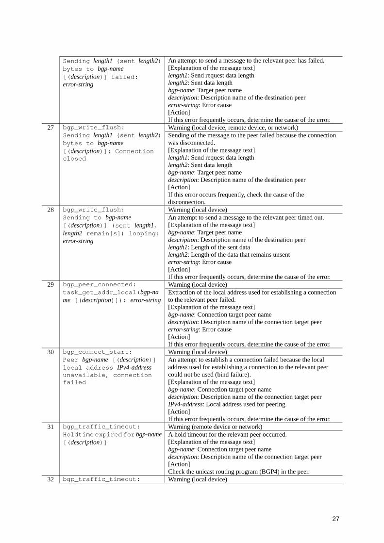
Sending length1 (sent length2) bytes to bgp-name [(description)] failed: error-string
An attempt to send a message to the relevant peer has failed. [Explanation of the message text] length1: Send request data length length2: Sent data length bgp-name: Target peer name description: Description name of the destination peer error-string: Error cause [Action] If this error frequently occurs, determine the cause of the error.
27 Warning (local device, remote device, or network)
bgp_write_flush: Sending length1 (sent length2) bytes to bgp-name [(description)]: Connection closed
Sending of the message to the peer failed because the connection was disconnected. [Explanation of the message text] length1: Send request data length length2: Sent data length bgp-name: Target peer name description: Description name of the destination peer [Action] If this error occurs frequently, check the cause of the disconnection.
28 Warning (local device)
bgp_write_flush: Sending to bgp-name [(description)] (sent length1, length2 remain[s]) looping: error-string
An attempt to send a message to the relevant peer timed out. [Explanation of the message text] bgp-name: Target peer name description: Description name of the destination peer length1: Length of the sent data length2: Length of the data that remains unsent error-string: Error cause [Action] If this error frequently occurs, determine the cause of the error.
29 Warning (local device)
bgp_peer_connected: task_get_addr_local(bgp-name [(description)]): error-string
Extraction of the local address used for establishing a connection to the relevant peer failed. [Explanation of the message text] bgp-name: Connection target peer name description: Description name of the connection target peer error-string: Error cause [Action] If this error frequently occurs, determine the cause of the error.
30 Warning (local device)
bgp_connect_start: Peer bgp-name [(description)] local address IPv4-address unavailable, connection failed
An attempt to establish a connection failed because the local address used for establishing a connection to the relevant peer could not be used (bind failure). [Explanation of the message text] bgp-name: Connection target peer name description: Description name of the connection target peer IPv4-address: Local address used for peering [Action] If this error frequently occurs, determine the cause of the error.
31 Warning (remote device or network)
bgp_traffic_timeout: Holdtime expired for bgp-name[(description)]
A hold timeout for the relevant peer occurred. [Explanation of the message text] bgp-name: Connection target peer name description: Description name of the connection target peer [Action] Check the unicast routing program (BGP4) in the peer.
32 bgp_traffic_timeout: Warning (local device)

28
Error sending KEEPALIVE to bgp-name [(description)]: error-string
An attempt to send a KEEPALIVE message to the relevant peer failed. [Explanation of the message text] bgp-name: Target peer name description: Description name of the destination peer error-string: Error cause [Action] If this error frequently occurs, determine the cause of the error.
33 Warning (local device)
bgp_listen_accept: accept(socket): error-string An attempt to accept a connection failed.
[Explanation of the message text] socket: Socket descriptor number error-string: Error cause [Action] If this error frequently occurs, determine the cause of the error.
34 Error (local device)
bgp_listen_accept: task_get_addr_local() failed, terminating!!
Extraction of the local address used for establishing a connection failed. The connection will be closed. [Explanation of the message text] None [Action] If this error frequently occurs, check the unicast routing program (BGP4) in the peer.
35 Error (local device)
bgp_listen_start: Couldn't get BGP listen socket!!
An attempt to create a socket for establishing a connection failed. The unicast routing program automatically restarts. [Explanation of the message text] None [Action] Take appropriate action by following the rtm aborted log.
36 Error (local device)
bgp_listen_start: listen: error-string Preparation for accepting a connection failed. The unicast routing
program automatically restarts. [Explanation of the message text] error-string: Error cause [Action] Take appropriate action by following the rtm aborted log.
37 Warning (local device)
bgp_set_peer_if: BGP peer bgp-name [(description)] interface not found. Leaving peer idled
The interface connected to the relevant peer was not found. [Explanation of the message text] bgp-name: Connection target peer name description: Description name of the connection target peer [Action] Check the configuration.
38 Warning (local device)
bgp_set_peer_if: BGP peer bgp-name [(description)] local address IPv4-address not on shared net. Leaving peer idled
The local address used for establishing a connection to the relevant peer is not in the same network. [Explanation of the message text] bgp-name: Connection target peer name description: Description name of the connection target peer IPv4-address: Local address used for establishing a connection [Action] Check the configuration.
39 bgp_pp_timeout: Warning (remote device or network)
29
Peer bgpp-name timed out waiting for OPEN
The timer for waiting for an OPEN message from the relevant peer timed out. [Explanation of the message text] bgpp-name: Connection target peer name [Action] Check the unicast routing program (BGP4) in the peer.
40 Warning (local device)
bgp_peer_init: BGP peer bgp-name [(description)] local address IPv4-address not found. Leaving peer idled
The interface for the local address used for establishing a connection to the relevant peer is not found. [Explanation of the message text] bgp-name: Connection target peer name description: Description name of the connection target peer IPv4-address: Local address used for establish a connection [Action] Check the configuration.
41 Error (remote device)
bgp_recv_v4_update: Peer bgp-name [(description)]: Strange message header length length
The message length in the message header of a message received from the relevant peer is invalid. [Explanation of the message text] bgp-name: Source peer name description: Description name of the source peer length: Message length of the received message header [Action] Check the unicast routing program (BGP4) in the peer.
42 Error (remote device)
bgp_recv_v4_update: Peer bgp-name [(description)] unrecognized message type type
The message type of a message received from the relevant peer is invalid. [Explanation of the message text] bgp-name: Source peer name description: Description name of the source peer type: Message type [Action] Check the unicast routing program (BGP4) in the peer.
43 Warning (remote device or network)
bgp_recv_v4_update: Received OPEN message from bgp-name [(description)], state is ESTABLISHED
An OPEN message was received from the relevant peer in the ESTABLISHED state. [Explanation of the message text] bgp-name: Source peer name description: Description name of the source peer [Action] The connection has become unstable. If this error occurs frequently, check the cause of the instability.
44 Error (remote device)
bgp_recv_v4_update: Peer bgp-name [(description)] UPDATE length length too small
The length of the UPDATE message from the relevant peer is too short. [Explanation of the message text] bgp-name: Source peer name description: Description name of the source peer length: Received data length [Action] Check the unicast routing program (BGP4) in the peer.
45 bgp_recv_v4_update: Error (remote device)
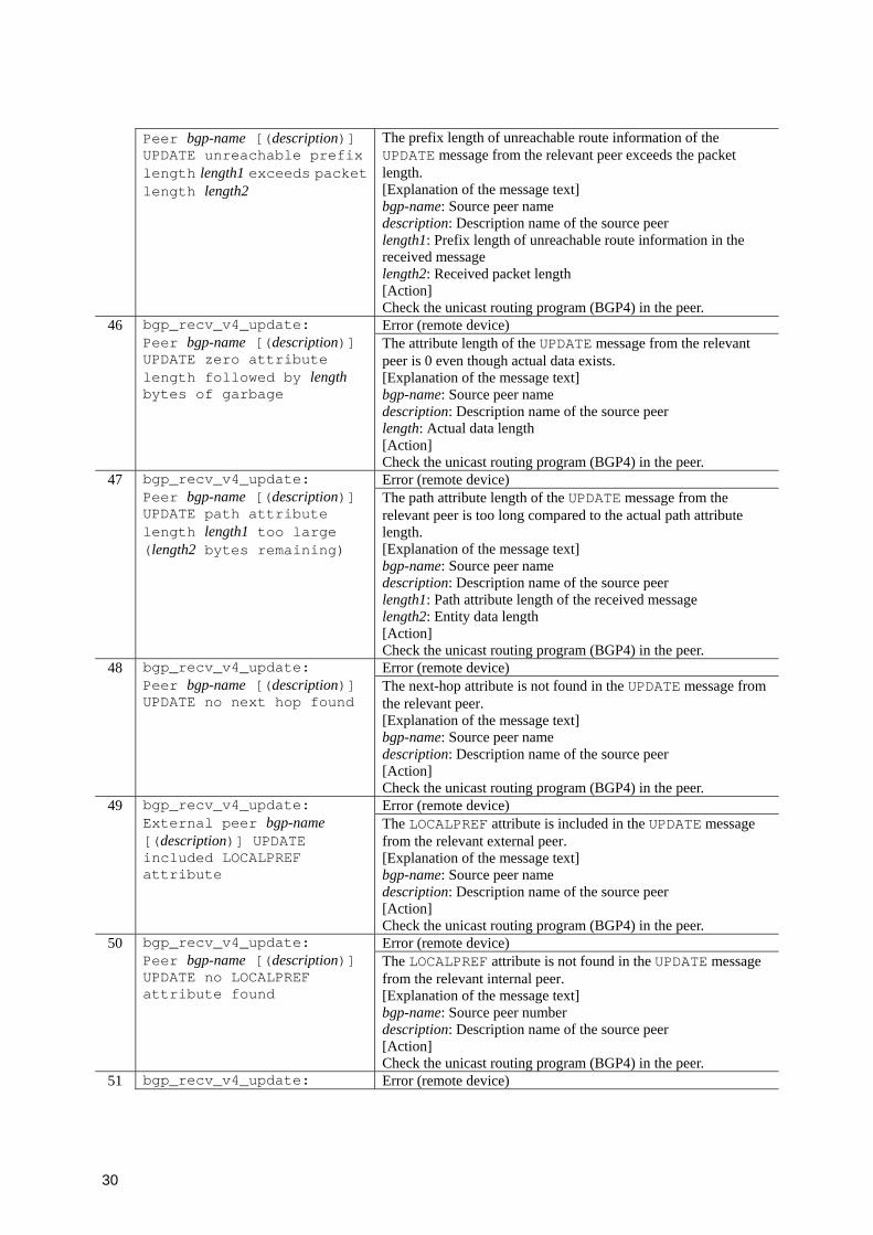
30
Peer bgp-name [(description)] UPDATE unreachable prefix length length1 exceeds packet length length2
The prefix length of unreachable route information of the UPDATE message from the relevant peer exceeds the packet length. [Explanation of the message text] bgp-name: Source peer name description: Description name of the source peer length1: Prefix length of unreachable route information in the received message length2: Received packet length [Action] Check the unicast routing program (BGP4) in the peer.
46 Error (remote device)
bgp_recv_v4_update: Peer bgp-name [(description)] UPDATE zero attribute length followed by length bytes of garbage
The attribute length of the UPDATE message from the relevant peer is 0 even though actual data exists. [Explanation of the message text] bgp-name: Source peer name description: Description name of the source peer length: Actual data length [Action] Check the unicast routing program (BGP4) in the peer.
47 Error (remote device)
bgp_recv_v4_update: Peer bgp-name [(description)] UPDATE path attribute length length1 too large (length2 bytes remaining)
The path attribute length of the UPDATE message from the relevant peer is too long compared to the actual path attribute length. [Explanation of the message text] bgp-name: Source peer name description: Description name of the source peer length1: Path attribute length of the received message length2: Entity data length [Action] Check the unicast routing program (BGP4) in the peer.
48 Error (remote device)
bgp_recv_v4_update: Peer bgp-name [(description)] UPDATE no next hop found
The next-hop attribute is not found in the UPDATE message from the relevant peer. [Explanation of the message text] bgp-name: Source peer name description: Description name of the source peer [Action] Check the unicast routing program (BGP4) in the peer.
49 Error (remote device)
bgp_recv_v4_update: External peer bgp-name [(description)] UPDATE included LOCALPREF attribute
The LOCALPREF attribute is included in the UPDATE message from the relevant external peer. [Explanation of the message text] bgp-name: Source peer name description: Description name of the source peer [Action] Check the unicast routing program (BGP4) in the peer.
50 Error (remote device)
bgp_recv_v4_update: Peer bgp-name [(description)] UPDATE no LOCALPREF attribute found
The LOCALPREF attribute is not found in the UPDATE message from the relevant internal peer. [Explanation of the message text] bgp-name: Source peer number description: Description name of the source peer [Action] Check the unicast routing program (BGP4) in the peer.
51 bgp_recv_v4_update: Error (remote device)
31
Peer bgp-name [(description)] UPDATE has path attributes but no reachable prefixes!
The UPDATE message from the relevant peer has path attributes but has no reachability information. [Explanation of the message text] bgp-name: Source peer name description: Description name of the source peer [Action] Check the unicast routing program (BGP4) in the peer.
52 Error (remote device)
bgp_recv_v4_unreach: Peer bgp-name [(description)] UPDATE: Invalid unreachable prefix length length
The prefix length of unreachable route information of the UPDATE message received from the relevant peer is invalid. [Explanation of the message text] bgp-name: Source peer name description: Description name of the source peer length: Prefix length in received messages [Action] Check the unicast routing program (BGP4) in the peer.
53 Error (remote device)
bgp_recv_v4_unreach: Peer bgp-name [(description)] UPDATE: Prefix length length1exceeds unreachable prefix data remaining (length2 bytes)
The prefix length of unreachable route information of the UPDATE message received from the relevant peer exceeds the prefix data of unreachable route information. [Explanation of the message text] bgp-name: Source peer name description: Description name of the source peer length1: Prefix length in received messages length2: Entity data length [Action] Check the unicast routing program (BGP4) in the peer.
54 Warning (remote device)
bgp_recv_v4_unreach: Peer bgp-name [(description)] UPDATE: Ignoring unreachable route with two or more labels (length1 of length2)
Routes of unreachable route information that has multiple labels of the UPDATE message received from the relevant peer are ignored. [Explanation of the message text] bgp-name: Source peer name description: Description name of the source peer length1 of length2: The location of invalid information in the message [Action] Check the unicast routing program (BGP4) in the peer.
55 Error (remote device)
bgp_recv_v4_unreach: Peer bgp-name [(description)] UPDATE: Ignoring unreachable route with RD 0 prefix (length1 of length2)
Routes of unreachable route information that has RD 0 of the UPDATE message received from the relevant peer are ignored. [Explanation of the message text] bgp-name: Source peer name description: Description name of the source peer length1 of length2: The location of invalid information in the message [Action] Check the unicast routing program (BGP4) in the peer.
56 bgp_recv_v4_unreach: Error (remote device)

32
Peer bgp-name [(description)] UPDATE: Ignoring invalid unreachable route IPv4-address/ mask (length1 of length2)
Invalid routes of unreachable route information of the UPDATE message received from the relevant peer are ignored. [Explanation of the message text] bgp-name: Source peer name description: Description name of the source peer IPv4-address: Destination address of unreachable route information mask: Network mask of unreachable route information length1 of length2: The location of invalid information in the message [Action] Check the unicast routing program (BGP4) in the peer.
57 Error (remote device)
bgp_recv_v4_reach: Peer bgp-name [(description)] AS as1 received path with first AS as2
The AS path whose next- hop AS number is as2 was received from the peer whose AS number is as1. [Explanation of the message text] bgp-name: Source peer name description: Description name of the source peer as1: AS number of the source peer as2: Next-hop AS number in the received message [Action] Check the unicast routing program (BGP4) in the peer.
58 Error (remote device)
bgp_recv_v4_reach: Peer bgp-name [(description)] UPDATE: Invalid prefix length length
The prefix length of the UPDATE message received from the relevant peer is invalid. [Explanation of the message text] bgp-name: Source peer name description: Description name of the source peer length: Prefix length in received messages [Action] Check the unicast routing program (BGP4) in the peer.
59 Error (remote device)
bgp_recv_v4_reach: Peer bgp-name [(description)] UPDATE: Prefix length length1exceeds prefix data remaining (length2 bytes)
The prefix length of the UPDATE message received from the relevant peer exceeds the actual prefix length. [Explanation of the message text] bgp-name: Source peer name description: Description name of the source peer length1: Prefix length in received messages length2: Actual prefix length [Action] Check the unicast routing program (BGP4) in the peer.
60 Warning (remote device)
bgp_recv_v4_reach: Peer bgp-name [(description)] UPDATE: Ignoring route with two or more labels (length1 of length2)
Routes that have multiple labels of the UPDATE message received from the relevant peer are ignored. [Explanation of the message text] bgp-name: Source peer name description: Description name of the source peer length1 of length2: The location of invalid information in the received message. [Action] Check the unicast routing program (BGP4) in the peer.
61 bgp_recv_v4_reach: Error (remote device)

33
Peer bgp-name [(description)] UPDATE: Ignoring route with RD 0 prefix (length1 of length2)
Routes that have RD 0 of the UPDATE message received from the relevant peer are ignored. [Explanation of the message text] bgp-name: Source peer name description: Description name of the source peer length1 of length2: The location of invalid information in the received message. [Action] Check the unicast routing program (BGP4) in the peer.
62 Error (remote device)
bgp_recv_v4_reach: Peer bgp-name [(description)] UPDATE:Included invalid route IPv4-address/ mask (length1of length2)
The UPDATE message received from the relevant peer includes invalid routes. [Explanation of the message text] bgp-name: Source peer name description: Description name of the source peer IPv4-address: Destination address mask: Network mask length1 of length2: The location of invalid information in the received message. [Action] Check the unicast routing program (BGP4) in the peer.
63 Warning (remote device)
bgp_recv_v4_reach: Ignoring network 0 route IPv4-address/ mask from peer bgp-name [(description)] (length1of length2)
Routes addressed to network 0 from the relevant peer are ignored.[Explanation of the message text] IPv4-address: Destination address mask: Network mask bgp-name: Source peer name description: Description name of the source peer length1 of length2: The location of invalid information in the received message. [Action] Check the unicast routing program (BGP4) in the peer.
64 Warning (remote device)
bgp_recv_v4_reach: Ignoring loopback route from peer bgp-name [(description)] (length1 of length2)
Loopback routes from the relevant peer are ignored. [Explanation of the message text] bgp-name: Source peer name description: Description name of the source peer length1 of length2: The location of invalid information in the received message. [Action] Check the unicast routing program (BGP4) in the peer.
65 Error (remote device)
bgp_recv_mp_unreach: Peer bgp-name [(description)] UPDATE: Invalid length of MP_UNREACH_NLRI attribute(length) : No address family
The length of the MP_UNREACH_NLRI attribute for the UPDATE message received from the peer is invalid. No address family exists. [Explanation of the message text] bgp-name: Source peer name description: Description name of the source peer length: Received MP_UNREACH_NLRI attribute length [Action] Check the unicast routing program (BGP4) in the peer.
66 bgp_recv_mp_unreach: Error (remote device)
34
Peer bgp-name [(description)] UPDATE: Invalid address family (address-family) in MP_UNREACH_NLRI attribute
The address family of the MP_UNREACH_NLRI attribute for the UPDATE message received from the peer is invalid. [Explanation of the message text] bgp-name: Source peer name description: Description name of the source peer address-family: Address family information of the received MP_UNREACH_NLRI attribute [Action] Check the unicast routing program (BGP4) in the peer.
67 Error (remote device)
bgp_recv_mp_reach: Peer bgp-name [(description)] UPDATE: Invalid length of MP_REACH_NLRI attribute(length) : No address family
The length of the MP_REACH_NLRI attribute for the UPDATE message received from the peer is invalid. No address family exists. [Explanation of the message text] bgp-name: Source peer name description: Description name of the source peer length: Received MP_REACH_NLRI attribute length [Action] Check the unicast routing program (BGP4) in the peer.
68 Error (remote device)
bgp_recv_mp_reach: Peer bgp-name [(description)] UPDATE: Invalid address family (address-family) in MP_REACH_NLRI attribute
The address family of the MP_REACH_NLRI attribute for the UPDATE message received from the relevant peer is invalid. [Explanation of the message text] bgp-name: Source peer name description: Description name of the source peer address-family: Address family information of the received MP_REACH_NLRI attribute [Action] Check the unicast routing program (BGP4) in the peer.
69 Error (remote device)
bgp_recv_mp_reach: Peer bgp-name [(description)] UPDATE: Invalid length of MP_REACH_NLRI attribute(length) : No nexthop length
The length of the MP_REACH_NLRI attribute for the UPDATE message received from the peer is invalid. No next-hop length exists. [Explanation of the message text] bgp-name: Source peer name description: Description name of the source peer length: Received MP_REACH_NLRI attribute length [Action] Check the unicast routing program (BGP4) in the peer.
70 Error (remote device)
bgp_recv_mp_reach: Peer bgp-name [(description)] UPDATE: Invalid nexthop length(length) in MP_REACH_NLRI attribute
The next-hop length of the MP_REACH_NLRI attribute for the UPDATE message received from the peer is invalid. [Explanation of the message text] bgp-name: Source peer name description: Description name of the source peer length: Next-hop length of the received MP_REACH_NLRI attribute [Action] Check the unicast routing program (BGP4) in the peer.
71 bgp_recv_mp_reach: Error (remote device)
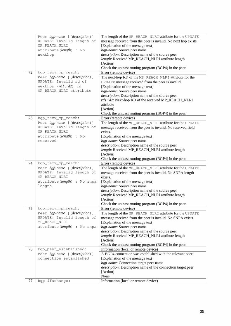
35
Peer bgp-name [(description)] UPDATE: Invalid length of MP_REACH_NLRI attribute(length) : No nexthop
The length of the MP_REACH_NLRI attribute for the UPDATE message received from the peer is invalid. No next hop exists. [Explanation of the message text] bgp-name: Source peer name description: Description name of the source peer length: Received MP_REACH_NLRI attribute length [Action] Check the unicast routing program (BGP4) in the peer.
72 Error (remote device)
bgp_recv_mp_reach: Peer bgp-name [(description)] UPDATE: Invalid rd of nexthop (rd1:rd2) in MP_REACH_NLRI attribute
The next-hop RD of the MP_REACH_NLRI attribute for the UPDATE message received from the peer is invalid. [Explanation of the message text] bgp-name: Source peer name description: Description name of the source peer rd1:rd2: Next-hop RD of the received MP_REACH_NLRI attribute [Action] Check the unicast routing program (BGP4) in the peer.
73 Error (remote device)
bgp_recv_mp_reach: Peer bgp-name [(description)] UPDATE: Invalid length of MP_REACH_NLRI attribute(length) : No reserved
The length of the MP_REACH_NLRI attribute for the UPDATE message received from the peer is invalid. No reserved field exists. [Explanation of the message text] bgp-name: Source peer name description: Description name of the source peer length: Received MP_REACH_NLRI attribute length [Action] Check the unicast routing program (BGP4) in the peer.
74 Error (remote device)
bgp_recv_mp_reach: Peer bgp-name [(description)] UPDATE: Invalid length of MP_REACH_NLRI attribute(length) : No snpa length
The length of the MP_REACH_NLRI attribute for the UPDATE message received from the peer is invalid. No SNPA length exists. [Explanation of the message text] bgp-name: Source peer name description: Description name of the source peer length: Received MP_REACH_NLRI attribute length [Action] Check the unicast routing program (BGP4) in the peer.
75 Error (remote device)
bgp_recv_mp_reach: Peer bgp-name [(description)] UPDATE: Invalid length of MP_REACH_NLRI attribute(length) : No snpa
The length of the MP_REACH_NLRI attribute for the UPDATE message received from the peer is invalid. No SNPA exists. [Explanation of the message text] bgp-name: Source peer name description: Description name of the source peer length: Received MP_REACH_NLRI attribute length [Action] Check the unicast routing program (BGP4) in the peer.
76 Information (local or remote device)
bgp_peer_established: Peer bgp-name [(description)] connection established
A BGP4 connection was established with the relevant peer. [Explanation of the message text] bgp-name: Connection target peer name description: Description name of the connection target peer [Action] None
77 bgp_ifachange: Information (local or remote device)
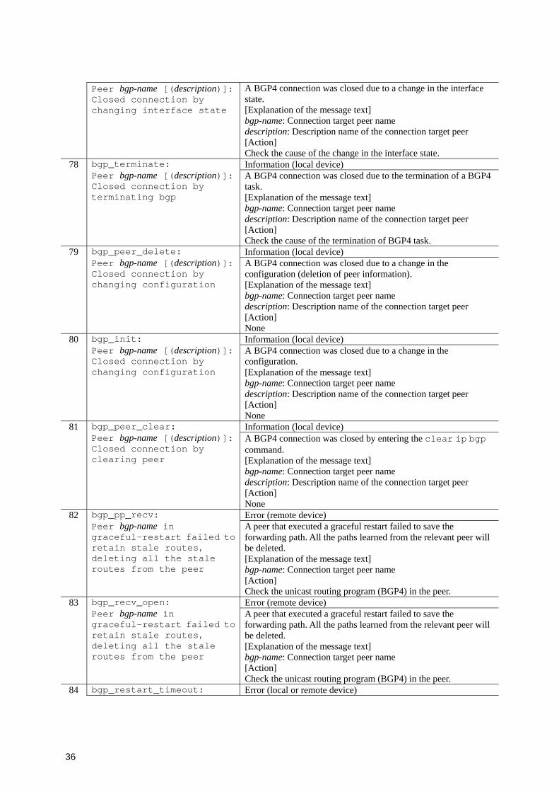
36
Peer bgp-name [(description)]: Closed connection by changing interface state
A BGP4 connection was closed due to a change in the interface state. [Explanation of the message text] bgp-name: Connection target peer name description: Description name of the connection target peer [Action] Check the cause of the change in the interface state.
78 Information (local device)
bgp_terminate: Peer bgp-name [(description)]: Closed connection by terminating bgp
A BGP4 connection was closed due to the termination of a BGP4 task. [Explanation of the message text] bgp-name: Connection target peer name description: Description name of the connection target peer [Action] Check the cause of the termination of BGP4 task.
79 Information (local device)
bgp_peer_delete: Peer bgp-name [(description)]: Closed connection by changing configuration
A BGP4 connection was closed due to a change in the configuration (deletion of peer information). [Explanation of the message text] bgp-name: Connection target peer name description: Description name of the connection target peer [Action] None
80 Information (local device)
bgp_init: Peer bgp-name [(description)]: Closed connection by changing configuration
A BGP4 connection was closed due to a change in the configuration. [Explanation of the message text] bgp-name: Connection target peer name description: Description name of the connection target peer [Action] None
81 Information (local device)
bgp_peer_clear: Peer bgp-name [(description)]: Closed connection by clearing peer
A BGP4 connection was closed by entering the clear ip bgp command. [Explanation of the message text] bgp-name: Connection target peer name description: Description name of the connection target peer [Action] None
82 Error (remote device)
bgp_pp_recv: Peer bgp-name in graceful-restart failed to retain stale routes, deleting all the stale routes from the peer
A peer that executed a graceful restart failed to save the forwarding path. All the paths learned from the relevant peer will be deleted. [Explanation of the message text] bgp-name: Connection target peer name [Action] Check the unicast routing program (BGP4) in the peer.
83 Error (remote device)
bgp_recv_open: Peer bgp-name in graceful-restart failed to retain stale routes, deleting all the stale routes from the peer
A peer that executed a graceful restart failed to save the forwarding path. All the paths learned from the relevant peer will be deleted. [Explanation of the message text] bgp-name: Connection target peer name [Action] Check the unicast routing program (BGP4) in the peer.
84 bgp_restart_timeout: Error (local or remote device)
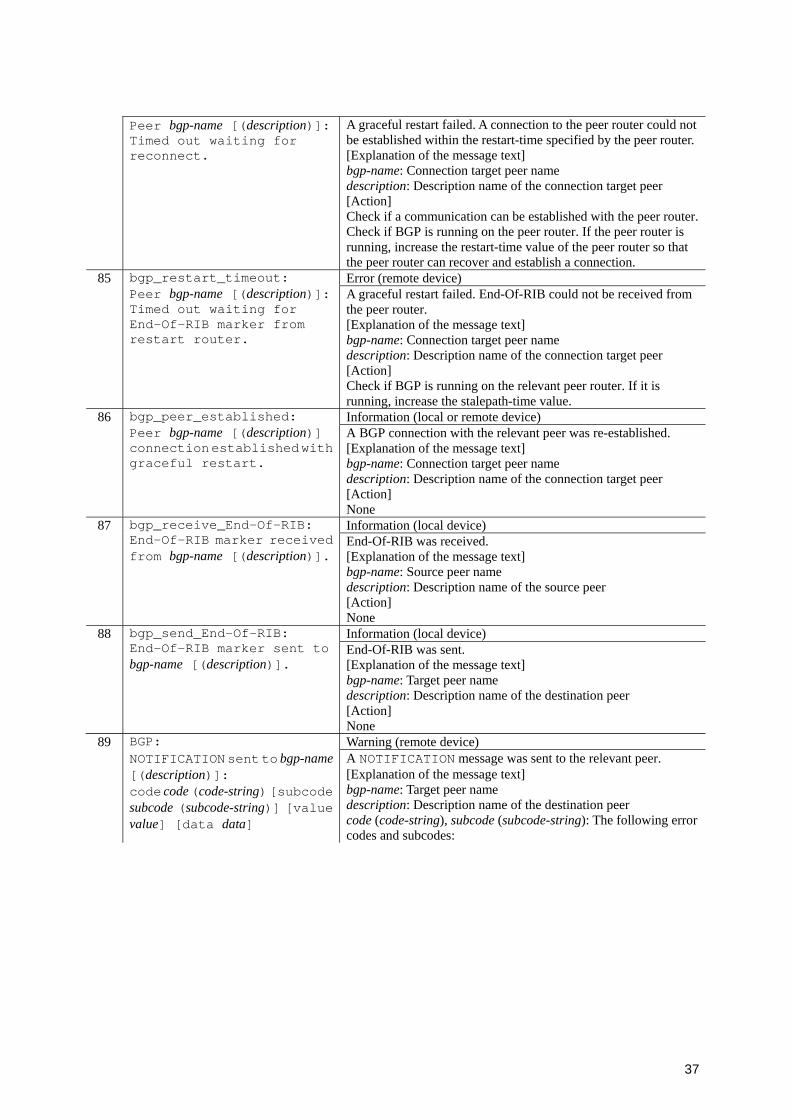
37
Peer bgp-name [(description)]: Timed out waiting for reconnect.
A graceful restart failed. A connection to the peer router could not be established within the restart-time specified by the peer router.[Explanation of the message text] bgp-name: Connection target peer name description: Description name of the connection target peer [Action] Check if a communication can be established with the peer router. Check if BGP is running on the peer router. If the peer router is running, increase the restart-time value of the peer router so that the peer router can recover and establish a connection.
85 Error (remote device)
bgp_restart_timeout: Peer bgp-name [(description)]: Timed out waiting for End-Of-RIB marker from restart router.
A graceful restart failed. End-Of-RIB could not be received from the peer router. [Explanation of the message text] bgp-name: Connection target peer name description: Description name of the connection target peer [Action] Check if BGP is running on the relevant peer router. If it is running, increase the stalepath-time value.
86 Information (local or remote device)
bgp_peer_established: Peer bgp-name [(description)] connection established with graceful restart.
A BGP connection with the relevant peer was re-established. [Explanation of the message text] bgp-name: Connection target peer name description: Description name of the connection target peer [Action] None
87 Information (local device)
bgp_receive_End-Of-RIB: End-Of-RIB marker received from bgp-name [(description)].
End-Of-RIB was received. [Explanation of the message text] bgp-name: Source peer name description: Description name of the source peer [Action] None
88 Information (local device)
bgp_send_End-Of-RIB: End-Of-RIB marker sent to bgp-name [(description)].
End-Of-RIB was sent. [Explanation of the message text] bgp-name: Target peer name description: Description name of the destination peer [Action] None
89 BGP: Warning (remote device) NOTIFICATION sent to bgp-name
[(description)]: code code (code-string) [subcode subcode (subcode-string)] [value value] [data data]
A NOTIFICATION message was sent to the relevant peer. [Explanation of the message text] bgp-name: Target peer name description: Description name of the destination peer code (code-string), subcode (subcode-string): The following error codes and subcodes:
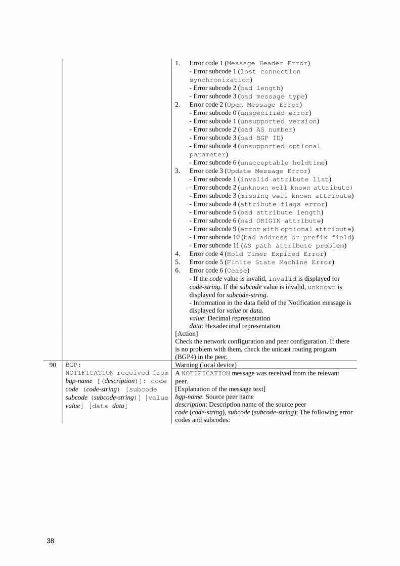
38
1. Error code 1 (Message Header Error) - Error subcode 1 (lost connection synchronization) - Error subcode 2 (bad length) - Error subcode 3 (bad message type)
2. Error code 2 (Open Message Error) - Error subcode 0 (unspecified error) - Error subcode 1 (unsupported version) - Error subcode 2 (bad AS number) - Error subcode 3 (bad BGP ID) - Error subcode 4 (unsupported optional parameter) - Error subcode 6 (unacceptable holdtime)
3. Error code 3 (Update Message Error) - Error subcode 1 (invalid attribute list) - Error subcode 2 (unknown well known attribute)- Error subcode 3 (missing well known attribute)- Error subcode 4 (attribute flags error) - Error subcode 5 (bad attribute length) - Error subcode 6 (bad ORIGIN attribute) - Error subcode 9 (error with optional attribute)- Error subcode 10 (bad address or prefix field)- Error subcode 11 (AS path attribute problem)
4. Error code 4 (Hold Timer Expired Error) 5. Error code 5 (Finite State Machine Error) 6. Error code 6 (Cease)
- If the code value is invalid, invalid is displayed for code-string. If the subcode value is invalid, unknown is displayed for subcode-string. - Information in the data field of the Notification message is displayed for value or data. value: Decimal representation data: Hexadecimal representation
[Action] Check the network configuration and peer configuration. If there is no problem with them, check the unicast routing program (BGP4) in the peer.
90 BGP: Warning (local device) NOTIFICATION received from
bgp-name [(description)]: code code (code-string) [subcode subcode (subcode-string)] [value value] [data data]
A NOTIFICATION message was received from the relevant peer. [Explanation of the message text] bgp-name: Source peer name description: Description name of the source peer code (code-string), subcode (subcode-string): The following error codes and subcodes:
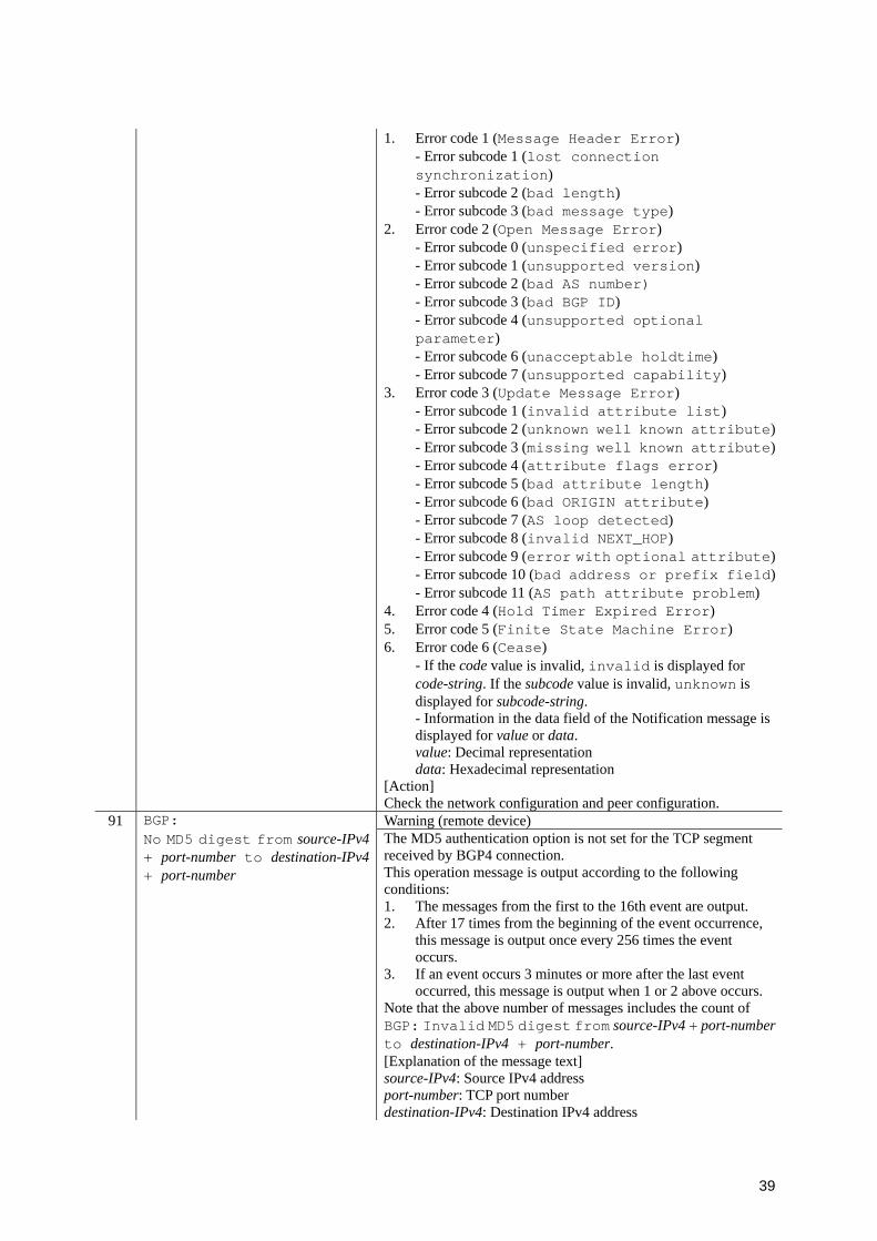
39
1. Error code 1 (Message Header Error) - Error subcode 1 (lost connection synchronization) - Error subcode 2 (bad length) - Error subcode 3 (bad message type)
2. Error code 2 (Open Message Error) - Error subcode 0 (unspecified error) - Error subcode 1 (unsupported version) - Error subcode 2 (bad AS number) - Error subcode 3 (bad BGP ID) - Error subcode 4 (unsupported optional parameter) - Error subcode 6 (unacceptable holdtime) - Error subcode 7 (unsupported capability)
3. Error code 3 (Update Message Error) - Error subcode 1 (invalid attribute list) - Error subcode 2 (unknown well known attribute)- Error subcode 3 (missing well known attribute)- Error subcode 4 (attribute flags error) - Error subcode 5 (bad attribute length) - Error subcode 6 (bad ORIGIN attribute) - Error subcode 7 (AS loop detected) - Error subcode 8 (invalid NEXT_HOP) - Error subcode 9 (error with optional attribute)- Error subcode 10 (bad address or prefix field)- Error subcode 11 (AS path attribute problem)
4. Error code 4 (Hold Timer Expired Error) 5. Error code 5 (Finite State Machine Error) 6. Error code 6 (Cease)
- If the code value is invalid, invalid is displayed for code-string. If the subcode value is invalid, unknown is displayed for subcode-string. - Information in the data field of the Notification message is displayed for value or data. value: Decimal representation data: Hexadecimal representation
[Action] Check the network configuration and peer configuration.
91 BGP: Warning (remote device) No MD5 digest from source-IPv4
+ port-number to destination-IPv4+ port-number
The MD5 authentication option is not set for the TCP segment received by BGP4 connection. This operation message is output according to the following conditions: 1. The messages from the first to the 16th event are output. 2. After 17 times from the beginning of the event occurrence,
this message is output once every 256 times the event occurs.
3. If an event occurs 3 minutes or more after the last event occurred, this message is output when 1 or 2 above occurs.
Note that the above number of messages includes the count of BGP: Invalid MD5 digest from source-IPv4 + port-numberto destination-IPv4 + port-number. [Explanation of the message text] source-IPv4: Source IPv4 address port-number: TCP port number destination-IPv4: Destination IPv4 address
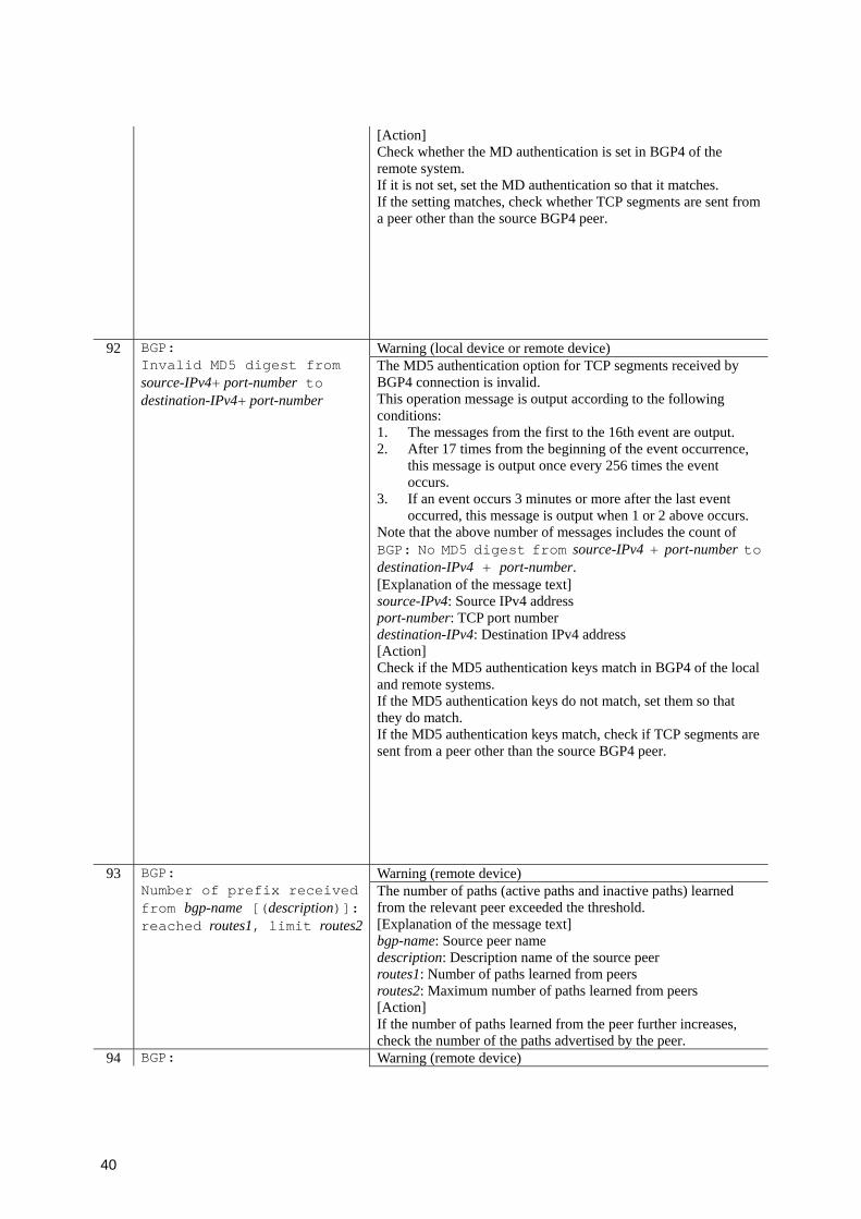
40
[Action] Check whether the MD authentication is set in BGP4 of the remote system. If it is not set, set the MD authentication so that it matches. If the setting matches, check whether TCP segments are sent from a peer other than the source BGP4 peer.
92 BGP: Warning (local device or remote device) Invalid MD5 digest from
source-IPv4+ port-number to destination-IPv4+ port-number
The MD5 authentication option for TCP segments received by BGP4 connection is invalid. This operation message is output according to the following conditions: 1. The messages from the first to the 16th event are output. 2. After 17 times from the beginning of the event occurrence,
this message is output once every 256 times the event occurs.
3. If an event occurs 3 minutes or more after the last event occurred, this message is output when 1 or 2 above occurs.
Note that the above number of messages includes the count of BGP: No MD5 digest from source-IPv4 + port-number to destination-IPv4 + port-number. [Explanation of the message text] source-IPv4: Source IPv4 address port-number: TCP port number destination-IPv4: Destination IPv4 address
[Action] Check if the MD5 authentication keys match in BGP4 of the local and remote systems. If the MD5 authentication keys do not match, set them so that they do match. If the MD5 authentication keys match, check if TCP segments are sent from a peer other than the source BGP4 peer.
93 BGP: Warning (remote device) Number of prefix received
from bgp-name [(description)]: reached routes1, limit routes2
The number of paths (active paths and inactive paths) learned from the relevant peer exceeded the threshold. [Explanation of the message text] bgp-name: Source peer name description: Description name of the source peer routes1: Number of paths learned from peers routes2: Maximum number of paths learned from peers [Action] If the number of paths learned from the peer further increases, check the number of the paths advertised by the peer.
94 BGP: Warning (remote device)
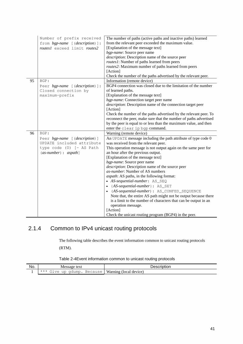
41
Number of prefix received from bgp-name [(description)]: routes1 exceed limit routes2
The number of paths (active paths and inactive paths) learned from the relevant peer exceeded the maximum value. [Explanation of the message text] bgp-name: Source peer name description: Description name of the source peer routes1: Number of paths learned from peers routes2: Maximum number of paths learned from peers [Action] Check the number of the paths advertised by the relevant peer.
95 BGP: Information (remote device) Peer bgp-name [(description)]:
Closed connection by maximum-prefix
BGP4 connection was closed due to the limitation of the number of learned paths. [Explanation of the message text] bgp-name: Connection target peer name description: Description name of the connection target peer [Action] Check the number of the paths advertised by the relevant peer. To reconnect the peer, make sure that the number of paths advertised by the peer is equal to or less than the maximum value, and then enter the clear ip bgp command.
96 BGP: Warning (remote device) Peer bgp-name [(description)]
UPDATE included attribute type code (0) [- AS Path (as-number): aspath]
An UPDATE message including the path attribute of type code 0 was received from the relevant peer. This operation message is not output again on the same peer for an hour after the previous output. [Explanation of the message text] bgp-name: Source peer name description: Description name of the source peer as-number: Number of AS numbers aspath: AS paths, in the following format: • AS-sequential-number: AS_SEQ • {AS-sequential-number}: AS_SET • (AS-sequential-number): AS_CONFED_SEQUENCE
Note that, the entire AS path might not be output because there is a limit to the number of characters that can be output in an operation message.
[Action] Check the unicast routing program (BGP4) in the peer.
2.1.4 Common to IPv4 unicast routing protocols
The following table describes the event information common to unicast routing protocols
(RTM).
Table 2-4Event information common to unicast routing protocols
No. Message text Description 1 *** Give up gdump. Because Warning (local device)

42
of no enough memory. Dump collection was stopped because the remaining memory capacity of the system temporarily fell below the preset value while unicast routing program control information dumps were being collected by the dump protocols unicast command. [Explanation of the message text] None [Action] There is not enough memory to execute the command. Review the capacity limitations.

43
2.2 IPv6 routing protocol information (RTM)
This section explains IPv6 routing protocol event information.
2.2.1 RIPng
The following table describes the event information for IPv6 routing protocol information
(RTM).
Table 2-5IPv6 routing protocol (RIPng) event information
No. Message text Description 1 Error (remote device)
ripng_recv: Bad metric (metric) for net prefix from source-address
Route information that has an invalid metric value (0, or 17 or larger) was received. [Explanation of the message text] metric: Metric value of the route information prefix: Route information destination prefix source-address: Source gateway address [Action] Check the unicast routing program (RIPng) for the source gateway.
2 Error (remote device)
ripng_recv: Bad prefixlen (pefix-length) for net prefix from source-address
Route information that has an invalid prefix length was received. [Explanation of the message text] pefix-length: Prefix length of the route information prefix: Route information destination source-address: Source gateway address [Action] Check the unicast routing program (RIPng) for the source gateway.
3 Error (remote device)
ripng_recv: Ignoring RIPng RIPng-commandpacket from source-address - ignoring invalid version packet
A received RIPng packet was ignored because the version field was invalid. [Explanation of the message text] RIPng-command: Received message type • Request, Response source-address: Source gateway address [Action] Check the unicast routing program (RIPng) for the source gateway.
4 Error (remote device)
ripng_recv: Packet hoplimit is hop-limit hop limit must be 255.
A received RIPng packet was ignored because the hop limit was invalid. [Explanation of the message text] hop-limit: Received hop limit [Action] Check the unicast routing program (RIPng) for the source gateway.
5 ripng_init: Error (local device)

44
Old copy of rtm is running Unicast routing program might already be running. The unicast routing program automatically restarts. [Explanation of the message text] None [Action] Take appropriate action by following the rtm aborted log.
6 Error (remote device)
ripng_recv: Ignoring RIPng RIPng-commandfrom source-address - source address is not link-local.
A received RIPng packet was ignored because the source address was not a link-local address. [Explanation of the message text] RIPng-command: Received message type source-address: Source gateway [Action] Check the unicast routing program (RIPng) for the source gateway.
7 Error (remote device)
ripng_recv: Ignoring RIPng RIPng-commandfrom source-address - source port is not valid.
A received RIPng packet was ignored because the source port was invalid. [Explanation of the message text] RIPng-command: Received message type source-address: Source gateway [Action] Check the unicast routing program (RIPng) for the source gateway.
8 Error (remote device)
ripng_recv: Ignoring RIPng RIPng-commandpacket from source-address - invalid or not implemented command
A received packet was ignored because the command was invalid or not implemented. [Explanation of the message text] RIPng-command: Received message type source-address: Source gateway [Action] Check the unicast routing program (RIPng) for the source gateway.
9 Error (remote device)
ripng_recv: Ignoring RIPng packet from source-address - too short packet (size)
A received packet was ignored because the packet length was shorter than the RIPng header. [Explanation of the message text] source-address: Source gateway size: Packet length [Action] Check the unicast routing program (RIPng) for the source gateway.
10 Error (remote device)
ripng_recv: Ignoring RIPng request packet from source-address - the routing entries of improper length
A received request packet was ignored because route information of invalid length was included. [Explanation of the message text] source-address: Source gateway [Action] Check the unicast routing program (RIPng) for the source gateway.
11 Error (remote device)
ripng_recv: Ignoring a routing entry of improper length - packet from source-address
Route information of invalid length was ignored. [Explanation of the message text] source-address: Source gateway [Action] Check the unicast routing program (RIPng) for the source gateway.
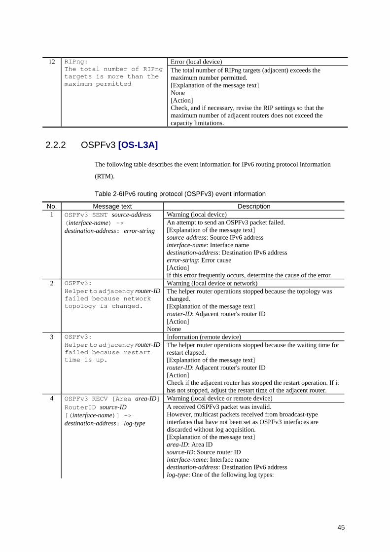
45
12 Error (local device)
RIPng: The total number of RIPng targets is more than the maximum permitted
The total number of RIPng targets (adjacent) exceeds the maximum number permitted. [Explanation of the message text] None [Action] Check, and if necessary, revise the RIP settings so that the maximum number of adjacent routers does not exceed the capacity limitations.
2.2.2 OSPFv3 [OS-L3A]
The following table describes the event information for IPv6 routing protocol information
(RTM).
Table 2-6IPv6 routing protocol (OSPFv3) event information
No. Message text Description Warning (local device) 1 OSPFv3 SENT source-address
(interface-name) -> destination-address: error-string
An attempt to send an OSPFv3 packet failed. [Explanation of the message text] source-address: Source IPv6 address interface-name: Interface name destination-address: Destination IPv6 address error-string: Error cause [Action] If this error frequently occurs, determine the cause of the error. Warning (local device or network) 2 OSPFv3:
Helper to adjacency router-ID failed because network topology is changed.
The helper router operations stopped because the topology was changed. [Explanation of the message text] router-ID: Adjacent router's router ID [Action] None Information (remote device) 3 OSPFv3:
Helper to adjacency router-ID failed because restart time is up.
The helper router operations stopped because the waiting time for restart elapsed. [Explanation of the message text] router-ID: Adjacent router's router ID [Action] Check if the adjacent router has stopped the restart operation. If it has not stopped, adjust the restart time of the adjacent router.
4 OSPFv3 RECV [Area area-ID] Warning (local device or remote device) RouterID source-ID
[(interface-name)] -> destination-address: log-type
A received OSPFv3 packet was invalid. However, multicast packets received from broadcast-type interfaces that have not been set as OSPFv3 interfaces are discarded without log acquisition.
[Explanation of the message text] area-ID: Area ID source-ID: Source router ID interface-name: Interface name destination-address: Destination IPv6 address log-type: One of the following log types:
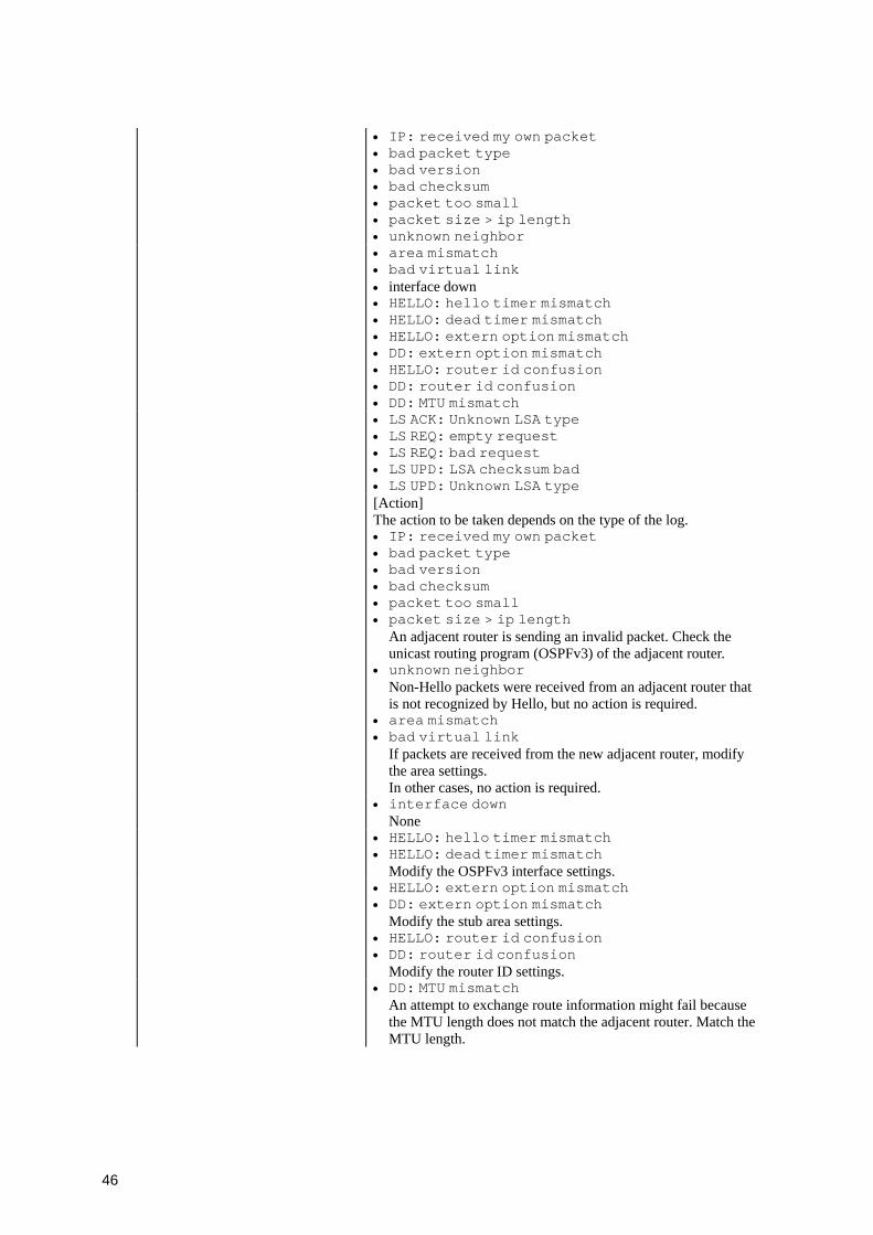
46
• IP: received my own packet • bad packet type • bad version • bad checksum • packet too small • packet size > ip length • unknown neighbor
• area mismatch • bad virtual link • interface down
• HELLO: hello timer mismatch • HELLO: dead timer mismatch • HELLO: extern option mismatch • DD: extern option mismatch • HELLO: router id confusion • DD: router id confusion • DD: MTU mismatch
• LS ACK: Unknown LSA type • LS REQ: empty request • LS REQ: bad request • LS UPD: LSA checksum bad • LS UPD: Unknown LSA type
[Action] The action to be taken depends on the type of the log. • IP: received my own packet • bad packet type • bad version • bad checksum • packet too small • packet size > ip length
An adjacent router is sending an invalid packet. Check the unicast routing program (OSPFv3) of the adjacent router.
• unknown neighbor Non-Hello packets were received from an adjacent router that is not recognized by Hello, but no action is required.
• area mismatch • bad virtual link
If packets are received from the new adjacent router, modify the area settings. In other cases, no action is required.
• interface down None
• HELLO: hello timer mismatch • HELLO: dead timer mismatch
Modify the OSPFv3 interface settings. • HELLO: extern option mismatch
• DD: extern option mismatch Modify the stub area settings.
• HELLO: router id confusion • DD: router id confusion
Modify the router ID settings. • DD: MTU mismatch
An attempt to exchange route information might fail because the MTU length does not match the adjacent router. Match the MTU length.

47
• LS ACK: Unknown LSA type • LS REQ: empty request • LS REQ: bad request • LS UPD: LSA checksum bad • LS UPD: Unknown LSA type
An adjacent router is sending an invalid packet. Check the unicast routing program (OSPFv3) of the adjacent router.
Error (local device) 5 OSPFv3: Conflict between LSDB LSID and route prefix /prefix-length - Export to OSPFASE Bypassed.
There is a conflict between LSDB LSID and the route. The unicast routing program automatically restarts. [Explanation of the message text] LSID: LSID of LSA prefix: Route information destination address prefix-length: Prefix length of the route information [Action] Take appropriate action by following the rtm aborted log. Warning (remote device or network) 6 OSPFv3:
Lost adjacency router-ID with interfaceID ID (interface-name) because no Hello received recently.
Adjacency was terminated because Hello packets that should be sent periodically from the adjacent router were not received during a given interval. This occurs when the adjacent router is deactivated, or if a problem occurs in communication between this device and adjacent router. [Explanation of the message text] router-ID: Adjacent router's router ID ID: ID of the interface of the adjacent router interface-name: Interface name [Action] If this warning occurs frequently, shorten the interval for sending Hello packets (hellointerval) or extend the maximum interval for receiving Hello packets (routerdeadinterval). Warning (remote device or network) 7 OSPFv3:
Lost adjacency router-ID with interfaceID ID (interface-name) because neighbor didn't receive my Hello recently.
Adjacency was terminated because the adjacent router no longer recognizes this device. This occurs when the adjacent router is restarted or Hello packets sent by this device are not properly received by the adjacent router. [Explanation of the message text] router-ID: Adjacent router's router ID ID: ID of the interface of the adjacent router interface-name: Interface name [Action] If this warning occurs frequently, extend the interval for sending Hello packets (hellointerval) and the maximum interval for receiving Hello packets (routerdeadinterval). Error (remote device) 8 OSPFv3:
Lost adjacency router-ID1 with interfaceID ID (interface-name) due to bad LS Request (LSID router-ID2 LS-type).
An adjacent router was lost due to an invalid LS request. [Explanation of the message text] router-ID1: Adjacent router's router ID ID: ID of the interface of the adjacent router interface-name: Interface name LSID: LSID of LSA router-ID2: LSA advertising router ID LS-type: LSA LS type code [Action] Check the unicast routing program (OSPFv3) of the adjacent router.
9 OSPFv3: Warning (local device or remote device)
48
Lost adjacency router-ID with interfaceID ID (interface-name) due to sequence mismatch (sequence1 versus sequence2)
An adjacent router was lost due to a sequence (or option) mismatch. [Explanation of the message text] router-ID: Adjacent router's router ID ID: ID of the interface of the adjacent router interface-name: Interface name sequence1: Sequence number in control data sequence2: Sequence number in the DD message [Action] If this warning occurs frequently, extend the interval for retransmitting OSPFv3 packets (retransmitinterval). Information (local or remote device) 10 OSPFv3:
Adjacency router-ID interface interface-name is established.
A connection with the OSPFv3 adjacent router was successfully established. [Explanation of the message text] router-ID: Adjacent router's router ID interface-name: Interface name [Action] None Error (local device) 11 OSPFv3:
Checksum failed at LSA type LS-type ID LSID adv-router router-ID in this system's LSDB that belongs to Area area-ID, Domain domain-ID.
LSDB checksum is invalid. The unicast routing program automatically restarts. [Explanation of the message text] LS-type: LSA LS type code LSID: LSID of LSA router-ID: LSA advertising router ID area-ID: LSA area ID domain-ID: LSA domain ID [Action] Take appropriate action by following the rtm aborted log. Information (local device) 12 OSPFv3:
Recovered from stub router (in domain domain-ID).
The stub router operation will now end. [Explanation of the message text] domain-ID: OSPFv3 domain ID [Action] None
2.2.3 BGP4+ [OS-L3A]
The following table describes the event information for IPv6 routing protocol information
(RTM).
Table 2-7IPv6 routing protocol (BGP4+) event information
No. Message text Description 1 Error (remote device)
bgp4+_check_auth: Synchronization failure with BGP task task-name
The value of the header marker of the message received by BGP4+ task was invalid. [Explanation of the message text] task-name: BGP4+ task name [Action] Check the unicast routing program (BGP4+) in the peer.
2 bgp4+_trace: Error (local device)
49
Unsupported BGP version version!!!
The BGP version number in control data was invalid. The unicast routing program automatically restarts. [Explanation of the message text] version: BGP version number in control data [Action] Take appropriate action by following the rtm aborted log.
3 Error (remote device)
bgp4+_log_notify: Notify message received from bgp-name [(description)] is truncated (length length)
The length of the NOTIFICATION message received from the relevant peer was invalid. [Explanation of the message text] bgp-name: Source peer name description: Description name of the source peer length: Received data length [Action] Check the unicast routing program (BGP4+) in the peer.
4 Warning (local device)
bgp4+_send: Sending length bytes to bgp-name [(description)] blocked (no spooling requested): error-string
An attempt to send a message to the relevant peer failed because the socket buffer became full. [Explanation of the message text] length: Send request message length bgp-name: Target peer name description: Description name of the destination peer error-string: Error cause [Action] If this error frequently occurs, determine the cause of the error.
5 Warning (local device)
bgp4+_send: Sending length bytes to bgp-name [(description)] failed: error-string
An attempt to send a message to the relevant peer failed. [Explanation of the message text] length: Send request message length bgp-name: Target peer name description: Description name of the destination peer error-string: Error cause [Action] If this error frequently occurs, determine the cause of the error.
6 Warning (local device, remote device, or network)
bgp4+_send: Sending length bytes to bgp-name [(description)]: connection closed
Sending of the message to the peer failed because the connection was disconnected. [Explanation of the message text] length: Send request message length bgp-name: Target peer name description: Description name of the destination peer [Action] If this error occurs frequently, check the cause of the disconnection.
7 Warning (local device)
bgp4+_send: sending to bgp-name [(description)] looping: error-string
An attempt to send a message to the relevant peer timed out. [Explanation of the message text] bgp-name: Target peer name description: Description name of the destination peer error-string: Error cause [Action] If this error frequently occurs, determine the cause of the error.
8 bgp4+_send_open: Error (local device)
50
Internal error! peer bgp-name [(description)], version version
The BGP version number of the OPEN message to be sent to the relevant peer was invalid. The unicast routing program automatically restarts. [Explanation of the message text] bgp-name: Target peer name description: Description name of the destination peer version: BGP version number in the send message [Action] Take appropriate action by following the rtm aborted log.
9 Error (remote device)
bgp4+_path_attr_error from routine: Update error subcode code (error-string) for peer bgp-name [(description)] detected. length bytes error data - 1st five:error-data
An error was detected in the UPDATE message received from the relevant peer. [Explanation of the message text] routine: Internal routine name code (error-string): Error cause bgp-name: Source peer name description: Description name of the source peer length: Error data length error-data: First five bytes of error data [Action] Check the unicast routing program (BGP4+) in the peer.
10 Warning (local device)
bgp4+_recv: Read from peer bgp-name [(description)] failed: error-string
An attempt to receive a message from the relevant peer failed. [Explanation of the message text] bgp-name: Source peer name description: Description name of the source peer error-string: Error cause [Action] If this error frequently occurs, determine the cause of the error.
11 Warning (local device, remote device, or network)
bgp4+_recv: Peer bgp-name [(description)]: Received unexpected EOF
An attempt to receive a message from the relevant peer failed due to disconnection. [Explanation of the message text] bgp-name: Source peer name description: Description name of the source peer [Action] If this error occurs frequently, check the cause of the disconnection.
12 Error (remote device)
bgp4+_read_message: Peer bgp-name [(description)]: message-type message arrived with length length
An invalid-length message was received from the relevant peer. [Explanation of the message text] bgp-name: Source peer name description: Description name of the source peer message-type: Received message type • invalid, Open, Update, Notification, KeepAlive length: Received data length [Action] Check the unicast routing program (BGP4+) in the peer.
13 bgp4+_read_message: Error (remote device)
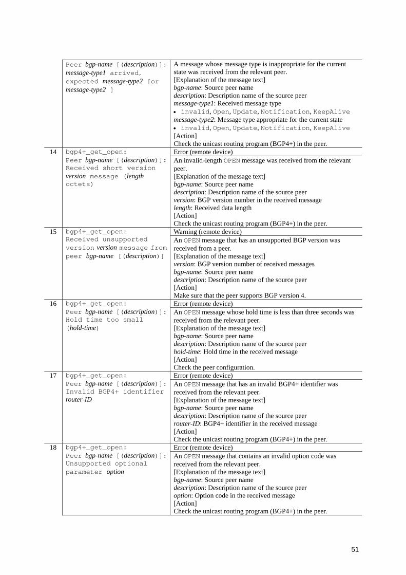
51
Peer bgp-name [(description)]: message-type1 arrived, expected message-type2 [or message-type2 ]
A message whose message type is inappropriate for the current state was received from the relevant peer. [Explanation of the message text] bgp-name: Source peer name description: Description name of the source peer message-type1: Received message type • invalid, Open, Update, Notification, KeepAlive message-type2: Message type appropriate for the current state • invalid, Open, Update, Notification, KeepAlive [Action] Check the unicast routing program (BGP4+) in the peer.
14 Error (remote device)
bgp4+_get_open: Peer bgp-name [(description)]: Received short version version message (length octets)
An invalid-length OPEN message was received from the relevant peer. [Explanation of the message text] bgp-name: Source peer name description: Description name of the source peer version: BGP version number in the received message length: Received data length [Action] Check the unicast routing program (BGP4+) in the peer.
15 Warning (remote device)
bgp4+_get_open: Received unsupported version version message from peer bgp-name [(description)]
An OPEN message that has an unsupported BGP version was received from a peer. [Explanation of the message text] version: BGP version number of received messages bgp-name: Source peer name description: Description name of the source peer [Action] Make sure that the peer supports BGP version 4.
16 Error (remote device)
bgp4+_get_open: Peer bgp-name [(description)]: Hold time too small (hold-time)
An OPEN message whose hold time is less than three seconds was received from the relevant peer. [Explanation of the message text] bgp-name: Source peer name description: Description name of the source peer hold-time: Hold time in the received message [Action] Check the peer configuration.
17 Error (remote device)
bgp4+_get_open: Peer bgp-name [(description)]: Invalid BGP4+ identifier router-ID
An OPEN message that has an invalid BGP4+ identifier was received from the relevant peer. [Explanation of the message text] bgp-name: Source peer name description: Description name of the source peer router-ID: BGP4+ identifier in the received message [Action] Check the unicast routing program (BGP4+) in the peer.
18 Error (remote device)
bgp4+_get_open: Peer bgp-name [(description)]: Unsupported optional parameter option
An OPEN message that contains an invalid option code was received from the relevant peer. [Explanation of the message text] bgp-name: Source peer name description: Description name of the source peer option: Option code in the received message [Action] Check the unicast routing program (BGP4+) in the peer.
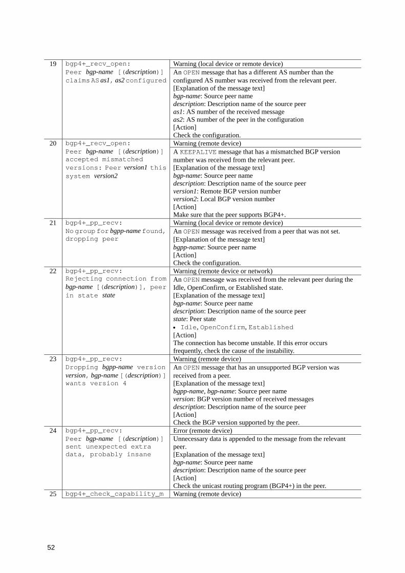
52
19 Warning (local device or remote device)
bgp4+_recv_open: Peer bgp-name [(description)] claims AS as1, as2 configured
An OPEN message that has a different AS number than the configured AS number was received from the relevant peer. [Explanation of the message text] bgp-name: Source peer name description: Description name of the source peer as1: AS number of the received message as2: AS number of the peer in the configuration [Action] Check the configuration.
20 Warning (remote device)
bgp4+_recv_open: Peer bgp-name [(description)] accepted mismatched versions: Peer version1 this system version2
A KEEPALIVE message that has a mismatched BGP version number was received from the relevant peer. [Explanation of the message text] bgp-name: Source peer name description: Description name of the source peer version1: Remote BGP version number version2: Local BGP version number [Action] Make sure that the peer supports BGP4+.
21 Warning (local device or remote device)
bgp4+_pp_recv: No group for bgpp-name found, dropping peer
An OPEN message was received from a peer that was not set. [Explanation of the message text] bgpp-name: Source peer name [Action] Check the configuration.
22 Warning (remote device or network)
bgp4+_pp_recv: Rejecting connection from bgp-name [(description)], peer in state state
An OPEN message was received from the relevant peer during the Idle, OpenConfirm, or Established state. [Explanation of the message text] bgp-name: Source peer name description: Description name of the source peer state: Peer state • Idle, OpenConfirm, Established [Action] The connection has become unstable. If this error occurs frequently, check the cause of the instability.
23 Warning (remote device)
bgp4+_pp_recv: Dropping bgpp-name version version, bgp-name [(description)] wants version 4
An OPEN message that has an unsupported BGP version was received from a peer. [Explanation of the message text] bgpp-name, bgp-name: Source peer name version: BGP version number of received messages description: Description name of the source peer [Action] Check the BGP version supported by the peer.
24 Error (remote device)
bgp4+_pp_recv: Peer bgp-name [(description)] sent unexpected extra data, probably insane
Unnecessary data is appended to the message from the relevant peer. [Explanation of the message text] bgp-name: Source peer name description: Description name of the source peer [Action] Check the unicast routing program (BGP4+) in the peer.
25 bgp4+_check_capability_m Warning (remote device)
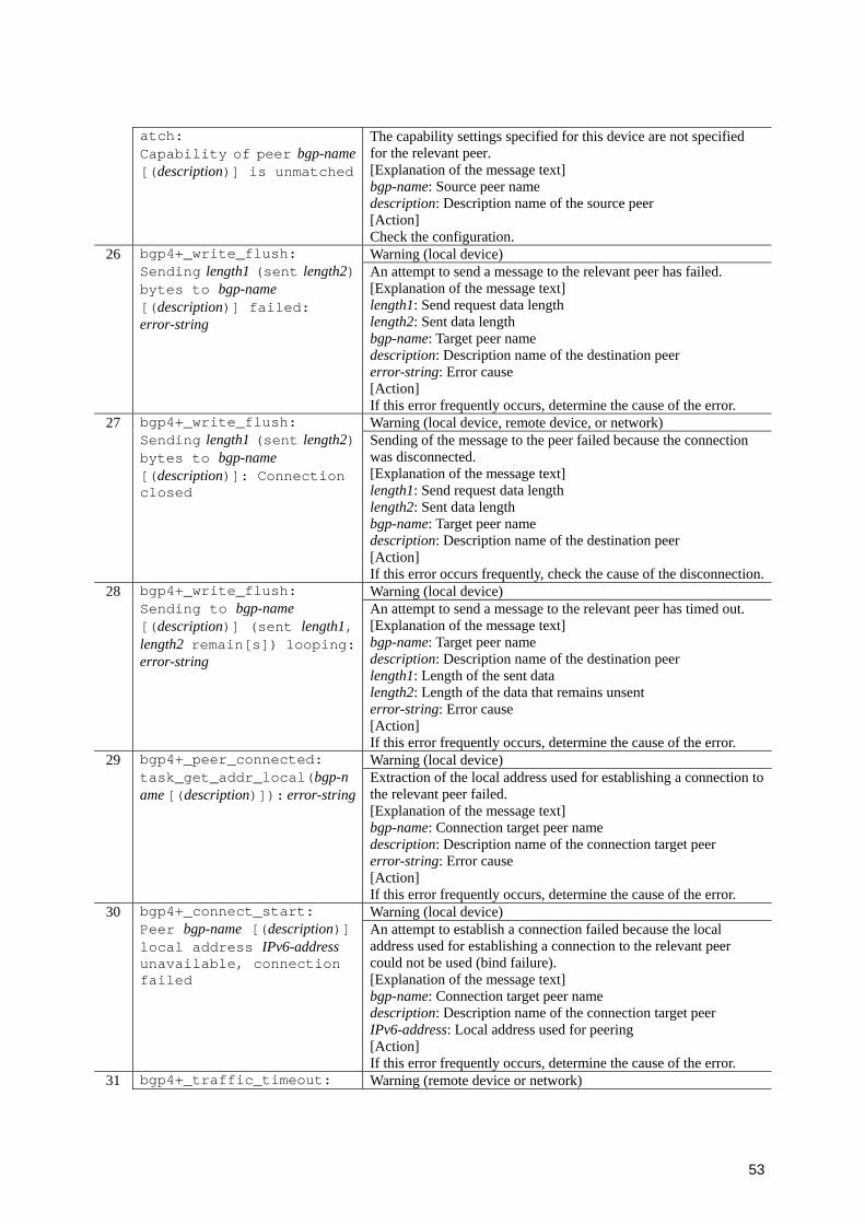
53
atch: Capability of peer bgp-name [(description)] is unmatched
The capability settings specified for this device are not specified for the relevant peer. [Explanation of the message text] bgp-name: Source peer name description: Description name of the source peer [Action] Check the configuration.
26 Warning (local device)
bgp4+_write_flush: Sending length1 (sent length2) bytes to bgp-name [(description)] failed: error-string
An attempt to send a message to the relevant peer has failed. [Explanation of the message text] length1: Send request data length length2: Sent data length bgp-name: Target peer name description: Description name of the destination peer error-string: Error cause [Action] If this error frequently occurs, determine the cause of the error.
27 Warning (local device, remote device, or network)
bgp4+_write_flush: Sending length1 (sent length2) bytes to bgp-name [(description)]: Connection closed
Sending of the message to the peer failed because the connection was disconnected. [Explanation of the message text] length1: Send request data length length2: Sent data length bgp-name: Target peer name description: Description name of the destination peer [Action] If this error occurs frequently, check the cause of the disconnection.
28 Warning (local device)
bgp4+_write_flush: Sending to bgp-name [(description)] (sent length1, length2 remain[s]) looping: error-string
An attempt to send a message to the relevant peer has timed out. [Explanation of the message text] bgp-name: Target peer name description: Description name of the destination peer length1: Length of the sent data length2: Length of the data that remains unsent error-string: Error cause [Action] If this error frequently occurs, determine the cause of the error.
29 Warning (local device)
bgp4+_peer_connected: task_get_addr_local(bgp-name [(description)]): error-string
Extraction of the local address used for establishing a connection to the relevant peer failed. [Explanation of the message text] bgp-name: Connection target peer name description: Description name of the connection target peer error-string: Error cause [Action] If this error frequently occurs, determine the cause of the error.
30 Warning (local device)
bgp4+_connect_start: Peer bgp-name [(description)] local address IPv6-address unavailable, connection failed
An attempt to establish a connection failed because the local address used for establishing a connection to the relevant peer could not be used (bind failure). [Explanation of the message text] bgp-name: Connection target peer name description: Description name of the connection target peer IPv6-address: Local address used for peering [Action] If this error frequently occurs, determine the cause of the error.
31 bgp4+_traffic_timeout: Warning (remote device or network)

54
Holdtime expired for bgp-name [(description)]
A hold timeout for the relevant peer occurred. [Explanation of the message text] bgp-name: Connection target peer name description: Description name of the connection target peer [Action] Check the unicast routing program (BGP4+) in the peer.
32 Warning (local device)
bgp4+_traffic_timeout: Error sending KEEPALIVE to bgp-name [(description)]: error-string
An attempt to send a KEEPALIVE message to the relevant peer failed. [Explanation of the message text] bgp-name: Target peer name description: Description name of the destination peer error-string: Error cause [Action] If this error frequently occurs, determine the cause of the error.
33 Warning (local device)
bgp4+_listen_accept: accept(socket): error-string An attempt to accept the connection failed.
[Explanation of the message text] socket: Socket descriptor number error-string: Error cause [Action] If this error frequently occurs, determine the cause of the error.
34 Error (local device)
bgp4+_listen_accept: bgp4+_get_peer_if() failed, terminating!!
Extraction of the link local address used for establishing a connection failed. The connection will be closed. [Explanation of the message text] None [Action] If this error frequently occurs, check the unicast routing program (BGP4+) in the peer.
35 Error (local device)
bgp4+_listen_accept: task_get_addr_local() failed, terminating!!
Extraction of the local address used for establishing a connection failed. The connection will be closed. [Explanation of the message text] None [Action] If this error frequently occurs, check the unicast routing program (BGP4+) in the peer.
36 Error (local device)
bgp4+_listen_start: Couldn't get BGP listen socket!!
An attempt to create a socket for establishing a connection failed. The unicast routing program automatically restarts. [Explanation of the message text] None [Action] Take appropriate action by following the rtm aborted log.
37 Error (local device)
bgp4+_listen_start: listen: error-string Preparation for accepting a connection failed. The unicast routing
program automatically restarts. [Explanation of the message text] error-string: Error cause [Action] Take appropriate action by following the rtm aborted log.
38 bgp4+_set_peer_if: Warning (local device)
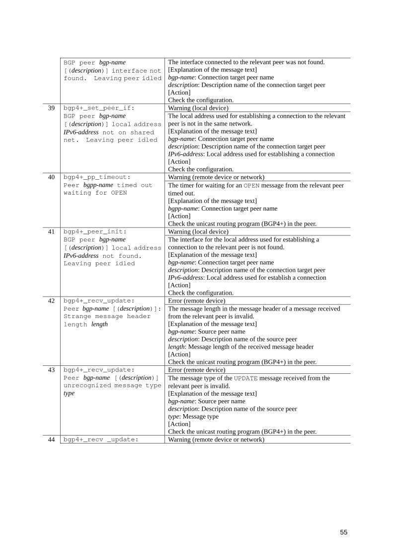
55
BGP peer bgp-name [(description)] interface not found. Leaving peer idled
The interface connected to the relevant peer was not found. [Explanation of the message text] bgp-name: Connection target peer name description: Description name of the connection target peer [Action] Check the configuration.
39 Warning (local device)
bgp4+_set_peer_if: BGP peer bgp-name [(description)] local address IPv6-address not on shared net. Leaving peer idled
The local address used for establishing a connection to the relevant peer is not in the same network. [Explanation of the message text] bgp-name: Connection target peer name description: Description name of the connection target peer IPv6-address: Local address used for establishing a connection [Action] Check the configuration.
40 Warning (remote device or network)
bgp4+_pp_timeout: Peer bgpp-name timed out waiting for OPEN
The timer for waiting for an OPEN message from the relevant peer timed out. [Explanation of the message text] bgpp-name: Connection target peer name [Action] Check the unicast routing program (BGP4+) in the peer.
41 Warning (local device)
bgp4+_peer_init: BGP peer bgp-name [(description)] local address IPv6-address not found. Leaving peer idled
The interface for the local address used for establishing a connection to the relevant peer is not found. [Explanation of the message text] bgp-name: Connection target peer name description: Description name of the connection target peer IPv6-address: Local address used for establish a connection [Action] Check the configuration.
42 Error (remote device)
bgp4+_recv_update: Peer bgp-name [(description)]: Strange message header length length
The message length in the message header of a message received from the relevant peer is invalid. [Explanation of the message text] bgp-name: Source peer name description: Description name of the source peer length: Message length of the received message header [Action] Check the unicast routing program (BGP4+) in the peer.
43 Error (remote device)
bgp4+_recv_update: Peer bgp-name [(description)] unrecognized message type type
The message type of the UPDATE message received from the relevant peer is invalid. [Explanation of the message text] bgp-name: Source peer name description: Description name of the source peer type: Message type [Action] Check the unicast routing program (BGP4+) in the peer.
44 bgp4+_recv _update: Warning (remote device or network)
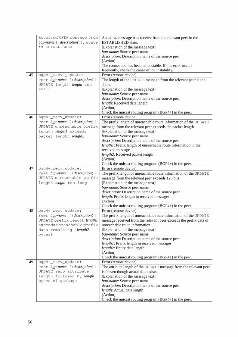
56
Received OPEN message from bgp-name [(description)], state is ESTABLISHED
An OPEN message was receive from the relevant peer in the ESTABLISHED state. [Explanation of the message text] bgp-name: Source peer name description: Description name of the source peer [Action] The connection has become unstable. If this error occurs frequently, check the cause of the instability.
45 Error (remote device)
bgp4+_recv _update: Peer bgp-name [(description)] UPDATE length length too small
The length of the UPDATE message from the relevant peer is too short. [Explanation of the message text] bgp-name: Source peer name description: Description name of the source peer length: Received data length [Action] Check the unicast routing program (BGP4+) in the peer.
46 Error (remote device)
bgp4+_recv_update: Peer bgp-name [(description)] UPDATE unreachable prefix length length1 exceeds packet length length2
The prefix length of unreachable route information of the UPDATE message from the relevant peer exceeds the packet length. [Explanation of the message text] bgp-name: Source peer name description: Description name of the source peer length1: Prefix length of unreachable route information in the received message length2: Received packet length [Action] Check the unicast routing program (BGP4+) in the peer.
47 Error (remote device)
bgp4+_recv_update: Peer bgp-name [(description)] UPDATE unreachable prefix length length too long
The prefix length of unreachable route information of the UPDATE message from the relevant peer exceeds 128 bits. [Explanation of the message text] bgp-name: Source peer name description: Description name of the source peer length: Prefix length in received messages [Action] Check the unicast routing program (BGP4+) in the peer.
48 Error (remote device)
bgp4+_recv_update: Peer bgp-name [(description)] UPDATE prefix length length1 exceeds unreachable prefix data remaining (length2 bytes)
The prefix length of unreachable route information of the UPDATE message received from the relevant peer exceeds the prefix data of unreachable route information. [Explanation of the message text] bgp-name: Source peer name description: Description name of the source peer length1: Prefix length in received messages length2: Entity data length [Action] Check the unicast routing program (BGP4+) in the peer.
49 Error (remote device)
bgp4+_recv_update: Peer bgp-name [(description)] UPDATE zero attribute length followed by length bytes of garbage
The attribute length of the UPDATE message from the relevant peer is 0 even though actual data exists. [Explanation of the message text] bgp-name: Source peer name description: Description name of the source peer length: Actual data length [Action] Check the unicast routing program (BGP4+) in the peer.
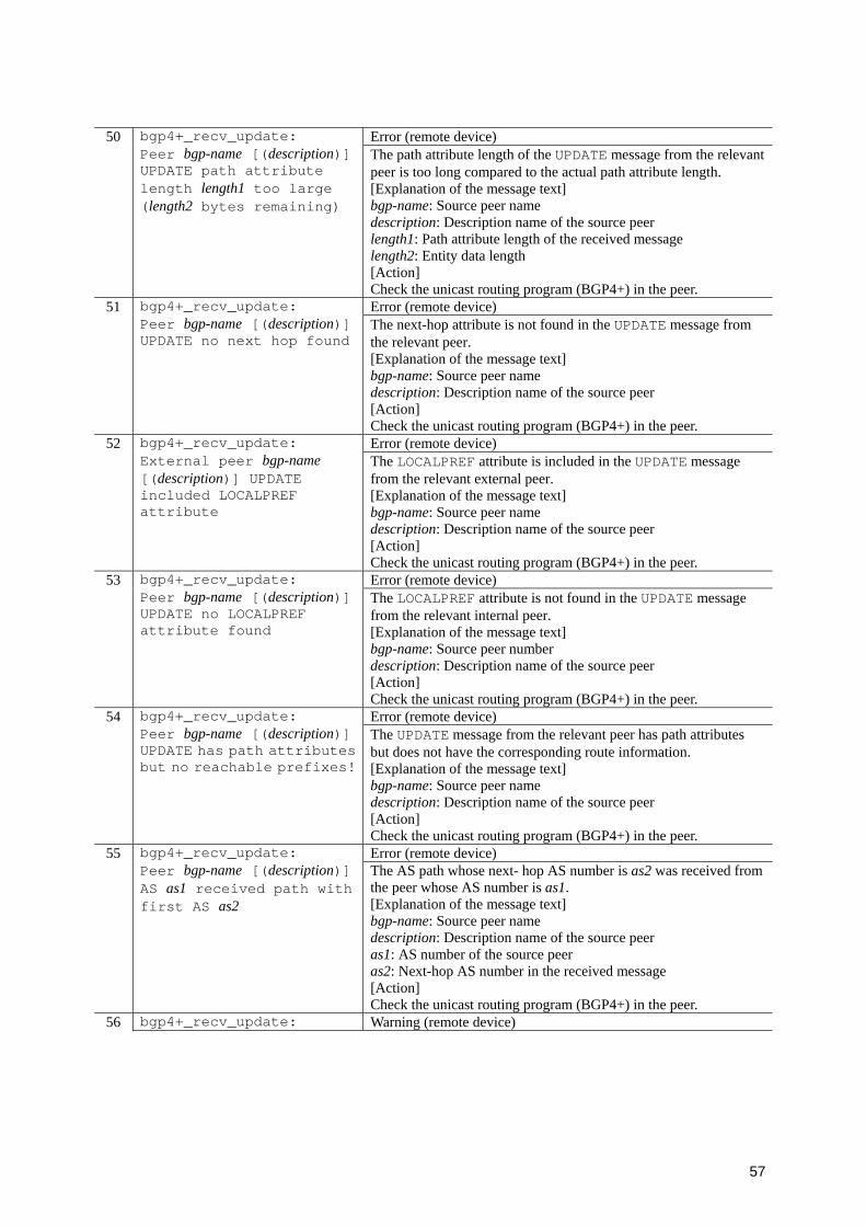
57
50 Error (remote device)
bgp4+_recv_update: Peer bgp-name [(description)] UPDATE path attribute length length1 too large (length2 bytes remaining)
The path attribute length of the UPDATE message from the relevant peer is too long compared to the actual path attribute length. [Explanation of the message text] bgp-name: Source peer name description: Description name of the source peer length1: Path attribute length of the received message length2: Entity data length [Action] Check the unicast routing program (BGP4+) in the peer.
51 Error (remote device)
bgp4+_recv_update: Peer bgp-name [(description)] UPDATE no next hop found
The next-hop attribute is not found in the UPDATE message from the relevant peer. [Explanation of the message text] bgp-name: Source peer name description: Description name of the source peer [Action] Check the unicast routing program (BGP4+) in the peer.
52 Error (remote device)
bgp4+_recv_update: External peer bgp-name [(description)] UPDATE included LOCALPREF attribute
The LOCALPREF attribute is included in the UPDATE message from the relevant external peer. [Explanation of the message text] bgp-name: Source peer name description: Description name of the source peer [Action] Check the unicast routing program (BGP4+) in the peer.
53 Error (remote device)
bgp4+_recv_update: Peer bgp-name [(description)] UPDATE no LOCALPREF attribute found
The LOCALPREF attribute is not found in the UPDATE message from the relevant internal peer. [Explanation of the message text] bgp-name: Source peer number description: Description name of the source peer [Action] Check the unicast routing program (BGP4+) in the peer.
54 Error (remote device)
bgp4+_recv_update: Peer bgp-name [(description)] UPDATE has path attributes but no reachable prefixes!
The UPDATE message from the relevant peer has path attributes but does not have the corresponding route information. [Explanation of the message text] bgp-name: Source peer name description: Description name of the source peer [Action] Check the unicast routing program (BGP4+) in the peer.
55 Error (remote device)
bgp4+_recv_update: Peer bgp-name [(description)] AS as1 received path with first AS as2
The AS path whose next- hop AS number is as2 was received from the peer whose AS number is as1. [Explanation of the message text] bgp-name: Source peer name description: Description name of the source peer as1: AS number of the source peer as2: Next-hop AS number in the received message [Action] Check the unicast routing program (BGP4+) in the peer.
56 bgp4+_recv_update: Warning (remote device)
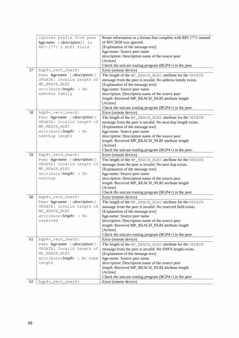
58
Ignores prefix from peer bgp-name [(description)] in RFC-1771's NLRI field
Route information in a format that complies with RFC1771 instead of RFC2858 was ignored. [Explanation of the message text] bgp-name: Source peer name description: Description name of the source peer [Action] Check the unicast routing program (BGP4+) in the peer.
57 Error (remote device)
bgp4+_recv_reach: Peer bgp-name [(description)] UPDATE: Invalid length of MP_REACH_NLRI attribute(length) : No address family
The length of the MP_REACH_NLRI attribute for the UPDATE message from the peer is invalid. No address family exists. [Explanation of the message text] bgp-name: Source peer name description: Description name of the source peer length: Received MP_REACH_NLRI attribute length [Action] Check the unicast routing program (BGP4+) in the peer.
58 Error (remote device)
bgp4+_recv_reach: Peer bgp-name [(description)] UPDATE: Invalid length of MP_REACH_NLRI attribute(length) : No nexthop length
The length of the MP_REACH_NLRI attribute for the UPDATE message from the peer is invalid. No next-hop length exists. [Explanation of the message text] bgp-name: Source peer name description: Description name of the source peer length: Received MP_REACH_NLRI attribute length [Action] Check the unicast routing program (BGP4+) in the peer.
59 Error (remote device)
bgp4+_recv_reach: Peer bgp-name [(description)] UPDATE: Invalid length of MP_REACH_NLRI attribute(length) : No nexthop
The length of the MP_REACH_NLRI attribute for the UPDATE message from the peer is invalid. No next hop exists. [Explanation of the message text] bgp-name: Source peer name description: Description name of the source peer length: Received MP_REACH_NLRI attribute length [Action] Check the unicast routing program (BGP4+) in the peer.
60 Error (remote device)
bgp4+_recv_reach: Peer bgp-name [(description)] UPDATE: Invalid length of MP_REACH_NLRI attribute(length) : No reserved
The length of the MP_REACH_NLRI attribute for the UPDATE message from the peer is invalid. No reserved field exists. [Explanation of the message text] bgp-name: Source peer name description: Description name of the source peer length: Received MP_REACH_NLRI attribute length [Action] Check the unicast routing program (BGP4+) in the peer.
61 Error (remote device)
bgp4+_recv_reach: Peer bgp-name [(description)] UPDATE: Invalid length of MP_REACH_NLRI attribute(length) : No snpa length
The length of the MP_REACH_NLRI attribute for the UPDATE message from the peer is invalid. No SNPA length exists. [Explanation of the message text] bgp-name: Source peer name description: Description name of the source peer length: Received MP_REACH_NLRI attribute length [Action] Check the unicast routing program (BGP4+) in the peer.
62 bgp4+_recv_reach: Error (remote device)

59
Peer bgp-name [(description)] UPDATE: Invalid length of MP_REACH_NLRI attribute(length) : No snpa
The length of the MP_REACH_NLRI attribute for the UPDATE message from the peer is invalid. No SNPA exists. [Explanation of the message text] bgp-name: Source peer name description: Description name of the source peer length: Received MP_REACH_NLRI attribute length [Action] Check the unicast routing program (BGP4+) in the peer.
63 Error (remote device)
bgp4+_recv_reach: Peer bgp-name [(description)] UPDATE multi-protocol prefix length length1 exceeds prefix data remaining (length2 bytes)
The prefix length of the route of the UPDATE message from the relevant peer is too long compared to the remaining data. [Explanation of the message text] bgp-name: Source peer name description: Description name of the source peer length1: Prefix length in received messages length2: Entity data length [Action] Check the unicast routing program (BGP4+) in the peer.
64 Error (remote device)
bgp4+_recv_reach: Peer bgp-name [(description)] UPDATE multi-protocol prefix length length too long
The prefix length of the route of the UPDATE message from the relevant peer exceeds 128 bits. [Explanation of the message text] bgp-name: Source peer name description: Description name of the source peer length: Received data length [Action] Check the unicast routing program (BGP4+) in the peer.
65 Error (remote device)
bgp4+_recv_reach: Peer bgp-name [(description)] bad next hop address length length
The next-hop address length of the route from the relevant peer is invalid. [Explanation of the message text] bgp-name: Source peer name description: Description name of the source peer length: Next-hop address length [Action] Check the unicast routing program (BGP4+) in the peer.
66 Error (remote device)
bgp4+_recv_reach: Peer bgp-name [(description)] next hop IPv6-address improper, ignoring routes in this update
The next-hop address of the route from the relevant peer is not in the same network. [Explanation of the message text] bgp-name: Source peer name description: Description name of the source peer IPv6-address: Next-hop address [Action] Check the unicast routing program (BGP4+) in the peer.
67 Error (remote device)
bgp4+_recv_reach: Peer bgp-name [(description)] unknown family/subfamily family/subfamily
Route information other than IPv6 unicast was received from the relevant peer. [Explanation of the message text] bgp-name: Source peer name description: Description name of the source peer family: Address family subfamily: Sub address family [Action] Check the unicast routing program (BGP4+) in the peer.
68 bgp4+_recv_unreach: Error (remote device)
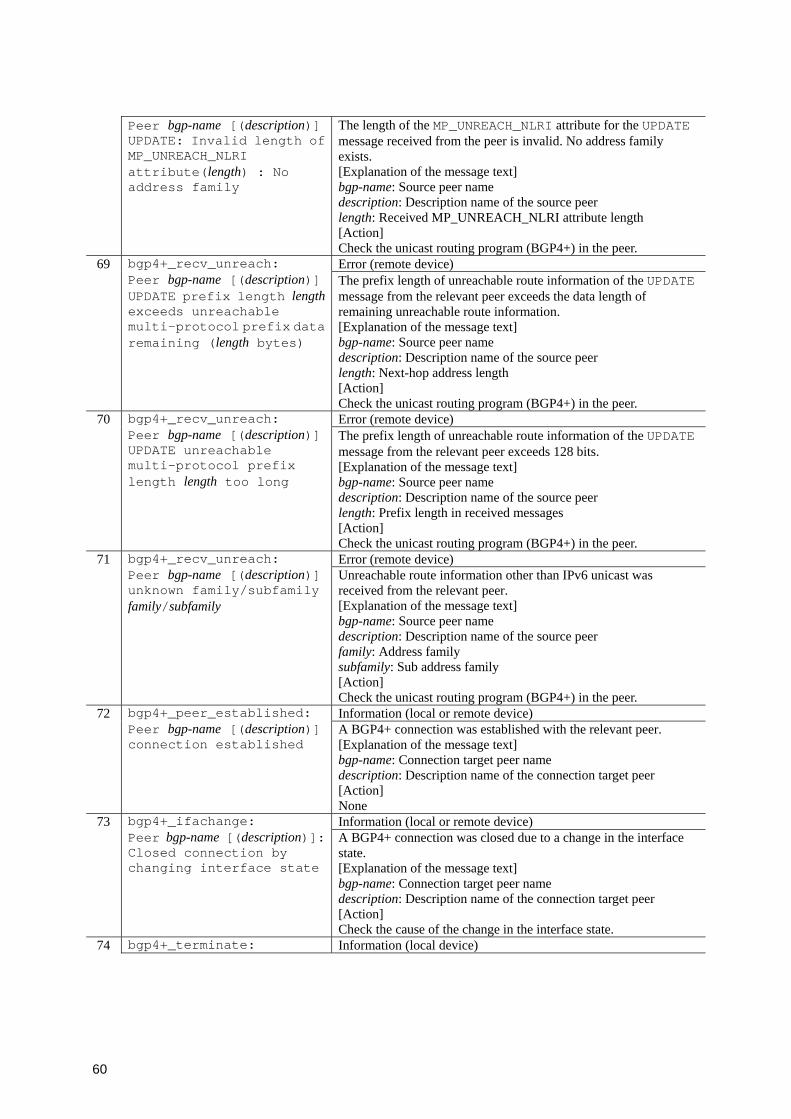
60
Peer bgp-name [(description)] UPDATE: Invalid length of MP_UNREACH_NLRI attribute(length) : No address family
The length of the MP_UNREACH_NLRI attribute for the UPDATE message received from the peer is invalid. No address family exists. [Explanation of the message text] bgp-name: Source peer name description: Description name of the source peer length: Received MP_UNREACH_NLRI attribute length [Action] Check the unicast routing program (BGP4+) in the peer.
69 Error (remote device)
bgp4+_recv_unreach: Peer bgp-name [(description)] UPDATE prefix length length exceeds unreachable multi-protocol prefix data remaining (length bytes)
The prefix length of unreachable route information of the UPDATE message from the relevant peer exceeds the data length of remaining unreachable route information. [Explanation of the message text] bgp-name: Source peer name description: Description name of the source peer length: Next-hop address length [Action] Check the unicast routing program (BGP4+) in the peer.
70 Error (remote device)
bgp4+_recv_unreach: Peer bgp-name [(description)] UPDATE unreachable multi-protocol prefix length length too long
The prefix length of unreachable route information of the UPDATE message from the relevant peer exceeds 128 bits. [Explanation of the message text] bgp-name: Source peer name description: Description name of the source peer length: Prefix length in received messages [Action] Check the unicast routing program (BGP4+) in the peer.
71 Error (remote device)
bgp4+_recv_unreach: Peer bgp-name [(description)] unknown family/subfamily family/subfamily
Unreachable route information other than IPv6 unicast was received from the relevant peer. [Explanation of the message text] bgp-name: Source peer name description: Description name of the source peer family: Address family subfamily: Sub address family [Action] Check the unicast routing program (BGP4+) in the peer.
72 Information (local or remote device)
bgp4+_peer_established: Peer bgp-name [(description)] connection established
A BGP4+ connection was established with the relevant peer. [Explanation of the message text] bgp-name: Connection target peer name description: Description name of the connection target peer [Action] None
73 Information (local or remote device)
bgp4+_ifachange: Peer bgp-name [(description)]: Closed connection by changing interface state
A BGP4+ connection was closed due to a change in the interface state. [Explanation of the message text] bgp-name: Connection target peer name description: Description name of the connection target peer [Action] Check the cause of the change in the interface state.
74 bgp4+_terminate: Information (local device)
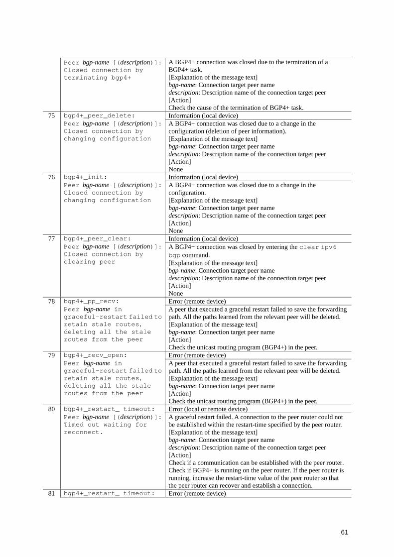
61
Peer bgp-name [(description)]: Closed connection by terminating bgp4+
A BGP4+ connection was closed due to the termination of a BGP4+ task. [Explanation of the message text] bgp-name: Connection target peer name description: Description name of the connection target peer [Action] Check the cause of the termination of BGP4+ task.
75 Information (local device)
bgp4+_peer_delete: Peer bgp-name [(description)]: Closed connection by changing configuration
A BGP4+ connection was closed due to a change in the configuration (deletion of peer information). [Explanation of the message text] bgp-name: Connection target peer name description: Description name of the connection target peer [Action] None
76 Information (local device)
bgp4+_init: Peer bgp-name [(description)]: Closed connection by changing configuration
A BGP4+ connection was closed due to a change in the configuration. [Explanation of the message text] bgp-name: Connection target peer name description: Description name of the connection target peer [Action] None
77 Information (local device)
bgp4+_peer_clear: Peer bgp-name [(description)]: Closed connection by clearing peer
A BGP4+ connection was closed by entering the clear ipv6 bgp command. [Explanation of the message text] bgp-name: Connection target peer name description: Description name of the connection target peer [Action] None
78 Error (remote device)
bgp4+_pp_recv: Peer bgp-name in graceful-restart failed to retain stale routes, deleting all the stale routes from the peer
A peer that executed a graceful restart failed to save the forwarding path. All the paths learned from the relevant peer will be deleted. [Explanation of the message text] bgp-name: Connection target peer name [Action] Check the unicast routing program (BGP4+) in the peer.
79 Error (remote device)
bgp4+_recv_open: Peer bgp-name in graceful-restart failed to retain stale routes, deleting all the stale routes from the peer
A peer that executed a graceful restart failed to save the forwarding path. All the paths learned from the relevant peer will be deleted. [Explanation of the message text] bgp-name: Connection target peer name [Action] Check the unicast routing program (BGP4+) in the peer.
80 Error (local or remote device)
bgp4+_restart_ timeout: Peer bgp-name [(description)]: Timed out waiting for reconnect.
A graceful restart failed. A connection to the peer router could not be established within the restart-time specified by the peer router. [Explanation of the message text] bgp-name: Connection target peer name description: Description name of the connection target peer [Action] Check if a communication can be established with the peer router. Check if BGP4+ is running on the peer router. If the peer router is running, increase the restart-time value of the peer router so that the peer router can recover and establish a connection.
81 bgp4+_restart_ timeout: Error (remote device)
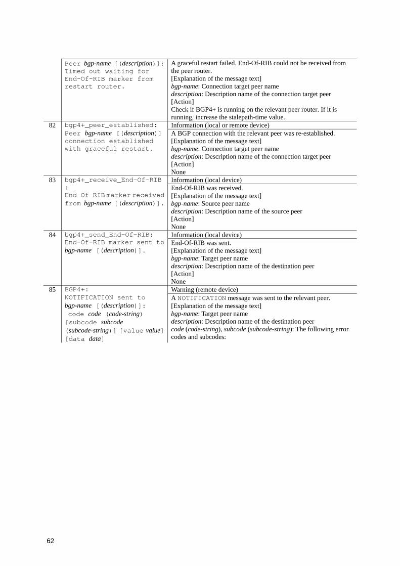
62
Peer bgp-name [(description)]: Timed out waiting for End-Of-RIB marker from restart router.
A graceful restart failed. End-Of-RIB could not be received from the peer router. [Explanation of the message text] bgp-name: Connection target peer name description: Description name of the connection target peer [Action] Check if BGP4+ is running on the relevant peer router. If it is running, increase the stalepath-time value.
82 Information (local or remote device)
bgp4+_peer_established: Peer bgp-name [(description)] connection established with graceful restart.
A BGP connection with the relevant peer was re-established. [Explanation of the message text] bgp-name: Connection target peer name description: Description name of the connection target peer [Action] None
83 Information (local device)
bgp4+_receive_End-Of-RIB: End-Of-RIB marker received from bgp-name [(description)].
End-Of-RIB was received. [Explanation of the message text] bgp-name: Source peer name description: Description name of the source peer [Action] None
84 Information (local device)
bgp4+_send_End-Of-RIB: End-Of-RIB marker sent to bgp-name [(description)].
End-Of-RIB was sent. [Explanation of the message text] bgp-name: Target peer name description: Description name of the destination peer [Action] None
85 BGP4+: Warning (remote device) NOTIFICATION sent to
bgp-name [(description)]: code code (code-string) [subcode subcode (subcode-string)] [value value] [data data]
A NOTIFICATION message was sent to the relevant peer. [Explanation of the message text] bgp-name: Target peer name description: Description name of the destination peer code (code-string), subcode (subcode-string): The following error codes and subcodes:
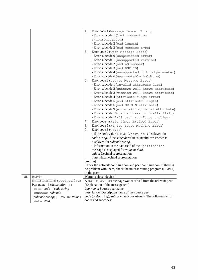
63
4. Error code 1 (Message Header Error) - Error subcode 1 (lost connection synchronization) - Error subcode 2 (bad length) - Error subcode 3 (bad message type)
5. Error code 2 (Open Message Error) - Error subcode 0 (unspecified error) - Error subcode 1 (unsupported version) - Error subcode 2 (bad AS number) - Error subcode 3 (bad BGP ID) - Error subcode 4 (unsupported optional parameter)- Error subcode 6 (unacceptable holdtime)
6. Error code 3 (Update Message Error) - Error subcode 1 (invalid attribute list) - Error subcode 2 (unknown well known attribute)- Error subcode 3 (missing well known attribute)- Error subcode 4 (attribute flags error) - Error subcode 5 (bad attribute length) - Error subcode 6 (bad ORIGIN attribute) - Error subcode 9 (error with optional attribute)- Error subcode 10 (bad address or prefix field) - Error subcode 11 (AS path attribute problem)
7. Error code 4 (Hold Timer Expired Error) 8. Error code 5 (Finite State Machine Error) 9. Error code 6 (Cease)
- If the code value is invalid, invalid is displayed for code-string. If the subcode value is invalid, unknown is displayed for subcode-string. - Information in the data field of the Notification message is displayed for value or data. value: Decimal representation data: Hexadecimal representation
[Action] Check the network configuration and peer configuration. If there is no problem with them, check the unicast routing program (BGP4+) in the peer.
86 BGP4+: Warning (local device) NOTIFICATION received from
bgp-name [(description)]: code code (code-string) [subcode subcode (subcode-string)] [value value] [data data]
A NOTIFICATION message was received from the relevant peer. [Explanation of the message text] bgp-name: Source peer name description: Description name of the source peer code (code-string), subcode (subcode-string): The following error codes and subcodes:
64
1. Error code 1 (Message Header Error) - Error subcode 1 (lost connection synchronization) - Error subcode 2 (bad length) - Error subcode 3 (bad message type)
2. Error code 2 (Open Message Error) - Error subcode 0 (unspecified error) - Error subcode 1 (unsupported version) - Error subcode 2 (bad AS number) - Error subcode 3 (bad BGP ID) - Error subcode 4 (unsupported optional parameter)- Error subcode 6 (unacceptable holdtime) - Error subcode 7 (unsupported capability)
3. Error code 3 (Update Message Error) - Error subcode 1 (invalid attribute list) - Error subcode 2 (unknown well known attribute)- Error subcode 3 (missing well known attribute)- Error subcode 4 (attribute flags error) - Error subcode 5 (bad attribute length) - Error subcode 6 (bad ORIGIN attribute) - Error subcode 7 (AS loop detected) - Error subcode 8 (invalid NEXT_HOP) - Error subcode 9 (error with optional attribute)- Error subcode 10 (bad address or prefix field) - Error subcode 11 (AS path attribute problem)
4. Error code 4 (Hold Timer Expired Error) 5. Error code 5 (Finite State Machine Error) 6. Error code 6 (Cease)
- If the code value is invalid, invalid is displayed for code-string. If the subcode value is invalid, unknown is displayed for subcode-string. - Information in the data field of the Notification message is displayed for value or data. value: Decimal representation data: Hexadecimal representation
[Action] Check the network configuration and peer configuration.
87 BGP4+: Warning (remote device) No MD5 digest from
source-IPv6+ port-number to destination-IPv6+ port-number
The MD5 authentication option is not set for the TCP segment received by BGP4+ connection. This operation message is output according to the following conditions: 1. The messages from the first to the 16th event are output. 2. After 17 times from the beginning of the event occurrence,
this message is output once every 256 times the event occurs. 3. If an event occurs 3 minutes or more after the last event
occurred, this message is output when 1 or 2 above occurs. Note that the above number of messages includes the count of BGP4+: Invalid MD5 digest from source-IPv6 + port-number to destination-IPv6 + port-number.

65
[Explanation of the message text] source-IPv6: Source IPv6 address port-number: TCP port number destination-IPv6: Destination IPv6 address [Action] Check whether the MD authentication is set in BGP4+ of the remote system. If it is not set, set the MD authentication so that it matches. If the setting matches, check whether TCP segments are sent from a peer other than the source BGP4+ peer.
88 BGP4+: Warning (local device or remote device) Invalid MD5 digest from
source-IPv6+ port-number to destination-IPv6+ port-number
The MD5 authentication option for TCP segments received by BGP4+ connection is invalid. This operation message is output according to the following conditions: 1. The messages from the first to the 16th event are output. 2. After 17 times from the beginning of the event occurrence,
this message is output once every 256 times the event occurs. 3. If an event occurs 3 minutes or more after the last event
occurred, this message is output when 1 or 2 above occurs. Note that the above number of messages includes the count of BGP4+: No MD5 digest from source-IPv6 + port-numberto destination-IPv6 + port-number.
[Explanation of the message text] source-IPv6: Source IPv6 address destination-IPv6: Destination IPv6 address port-number: TCP port number [Action] Check if the MD5 authentication keys match in BGP4+ of the local and remote systems. If the MD5 authentication keys do not match, set them so that they do match. If the MD5 authentication keys match, check if TCP segments are sent from a peer other than the source BGP4+ peer.
89 BGP4+: Warning (remote device) Number of prefix received
from bgp-name [(description)]: reached routes1, limit routes2
The number of paths (active paths and inactive paths) learned from the relevant peer exceeded the threshold. [Explanation of the message text] bgp-name: Source peer name description: Description name of the source peer routes1: Number of paths learned from peers routes2: Maximum number of paths learned from peers [Action] If the number of paths learned from the peer further increases, check the number of the paths advertised by the peer.
90 BGP4+: Warning (remote device) Number of prefix received
from bgp-name [(description)]: routes1 exceed limit routes2
The number of paths (active paths and inactive paths) learned from the relevant peer exceeded the maximum value. [Explanation of the message text] bgp-name: Source peer name description: Description name of the source peer routes1: Number of paths learned from peers routes2: Maximum number of paths learned from peers [Action] Check the number of the paths advertised by the relevant peer.
91 BGP4+: Information (remote device)
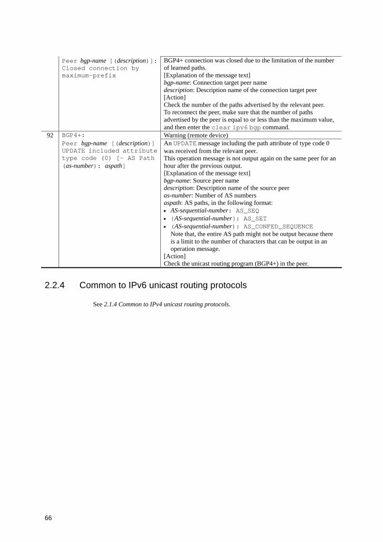
66
Peer bgp-name [(description)]: Closed connection by maximum-prefix
BGP4+ connection was closed due to the limitation of the number of learned paths. [Explanation of the message text] bgp-name: Connection target peer name description: Description name of the connection target peer [Action] Check the number of the paths advertised by the relevant peer. To reconnect the peer, make sure that the number of paths advertised by the peer is equal to or less than the maximum value, and then enter the clear ipv6 bgp command.
92 BGP4+: Warning (remote device) Peer bgp-name [(description)]
UPDATE included attribute type code (0) [- AS Path (as-number): aspath]
An UPDATE message including the path attribute of type code 0 was received from the relevant peer. This operation message is not output again on the same peer for an hour after the previous output. [Explanation of the message text] bgp-name: Source peer name description: Description name of the source peer as-number: Number of AS numbers aspath: AS paths, in the following format: • AS-sequential-number: AS_SEQ • {AS-sequential-number}: AS_SET • (AS-sequential-number): AS_CONFED_SEQUENCE
Note that, the entire AS path might not be output because there is a limit to the number of characters that can be output in an operation message.
[Action] Check the unicast routing program (BGP4+) in the peer.
2.2.4 Common to IPv6 unicast routing protocols
See 2.1.4 Common to IPv4 unicast routing protocols.
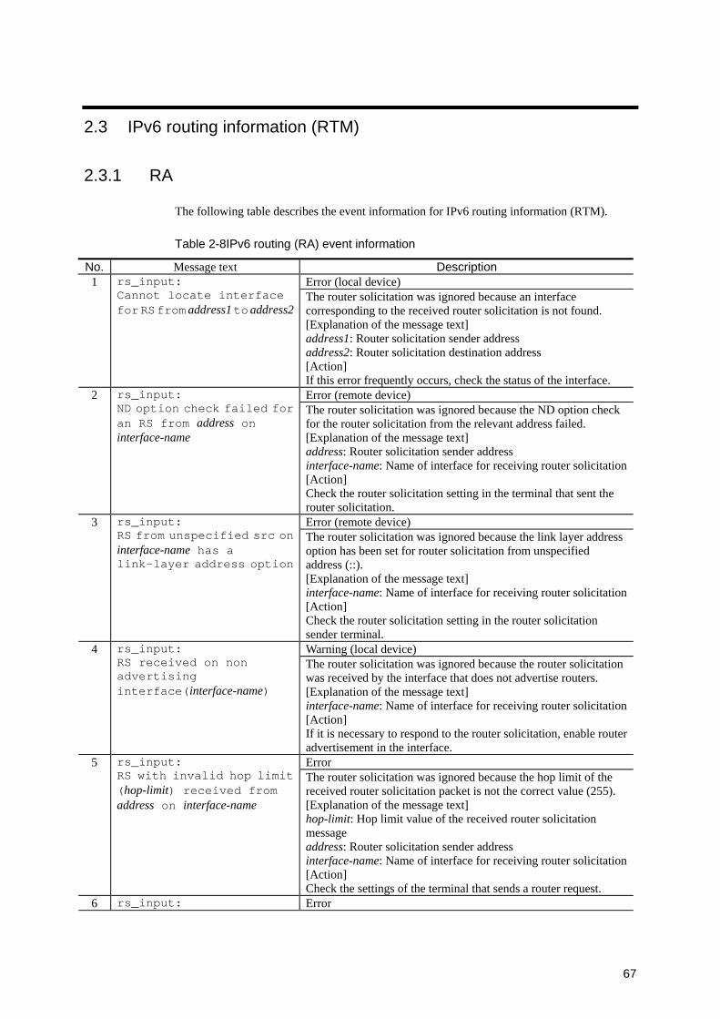
67
2.3 IPv6 routing information (RTM)
2.3.1 RA
The following table describes the event information for IPv6 routing information (RTM).
Table 2-8IPv6 routing (RA) event information
No. Message text Description Error (local device) 1 rs_input:
Cannot locate interface for RS from address1 to address2
The router solicitation was ignored because an interface corresponding to the received router solicitation is not found. [Explanation of the message text] address1: Router solicitation sender address address2: Router solicitation destination address [Action] If this error frequently occurs, check the status of the interface. Error (remote device) 2 rs_input:
ND option check failed for an RS from address on interface-name
The router solicitation was ignored because the ND option check for the router solicitation from the relevant address failed. [Explanation of the message text] address: Router solicitation sender address interface-name: Name of interface for receiving router solicitation[Action] Check the router solicitation setting in the terminal that sent the router solicitation. Error (remote device) 3 rs_input:
RS from unspecified src on interface-name has a link-layer address option
The router solicitation was ignored because the link layer address option has been set for router solicitation from unspecified address (::). [Explanation of the message text] interface-name: Name of interface for receiving router solicitation[Action] Check the router solicitation setting in the router solicitation sender terminal. Warning (local device) 4 rs_input:
RS received on non advertising interface(interface-name)
The router solicitation was ignored because the router solicitation was received by the interface that does not advertise routers. [Explanation of the message text] interface-name: Name of interface for receiving router solicitation[Action] If it is necessary to respond to the router solicitation, enable router advertisement in the interface. Error 5 rs_input:
RS with invalid hop limit (hop-limit) received from address on interface-name
The router solicitation was ignored because the hop limit of the received router solicitation packet is not the correct value (255). [Explanation of the message text] hop-limit: Hop limit value of the received router solicitation message address: Router solicitation sender address interface-name: Name of interface for receiving router solicitation[Action] Check the settings of the terminal that sends a router request.
6 rs_input: Error
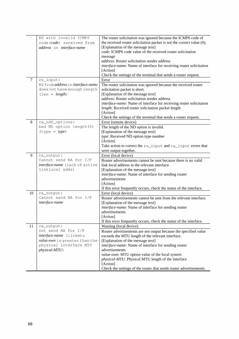
68
RS with invalid ICMP6 code(code) received from address on interface-name
The router solicitation was ignored because the ICMP6 code of the received router solicitation packet is not the correct value (0). [Explanation of the message text] code: ICMP6 code value of the received router solicitation message address: Router solicitation sender address interface-name: Name of interface for receiving router solicitation[Action] Check the settings of the terminal that sends a router request. Error 7 rs_input:
RS from address on interface-name does not have enough length (len = length)
The router solicitation was ignored because the received router solicitation packet is short. [Explanation of the message text] address: Router solicitation sender address interface-name: Name of interface for receiving router solicitationlength: Received router solicitation packet length [Action] Check the settings of the terminal that sends a router request. Error (remote device) 8 ra_nd6_options:
bad ND option length(0) (type = type)
The length of the ND option is invalid. [Explanation of the message text] type: Received ND option type number [Action] Take action to correct the rs_input and ra_input errors that were output together. Error (local device) 9 ra_output:
Cannot send RA for I/F interface-name (lack of active linklocal addr)
Router advertisements cannot be sent because there is no valid link local address in the relevant interface. [Explanation of the message text] interface-name: Name of interface for sending router advertisements [Action] If this error frequently occurs, check the status of the interface. Error (local device) 10 ra_output:
Cannot send RA for I/F interface-name
Router advertisements cannot be sent from the relevant interface. [Explanation of the message text] interface-name: Name of interface for sending router advertisements [Action] If this error frequently occurs, check the status of the interface. Warning (local device) 11 ra_output:
not send RA for I/F interface-name (linkmtu value-own is greater than the physical interface MTU physical-MTU)
Router advertisements are not output because the specified value exceeds the MTU length of the relevant interface. [Explanation of the message text] interface-name: Name of interface for sending router advertisements value-own: MTU option value of the local system physical-MTU: Physical MTU length of the interface [Action] Check the settings of the router that sends router advertisements.
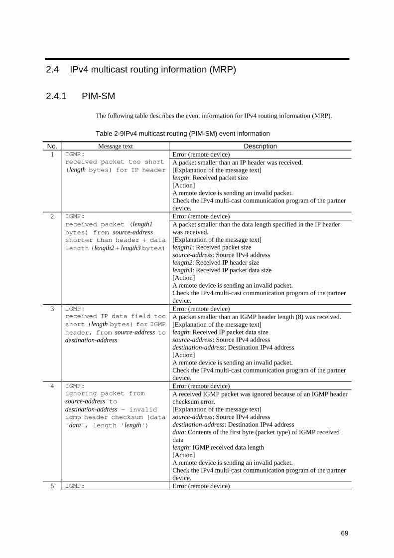
69
2.4 IPv4 multicast routing information (MRP)
2.4.1 PIM-SM
The following table describes the event information for IPv4 routing information (MRP).
Table 2-9IPv4 multicast routing (PIM-SM) event information
No. Message text Description 1 Error (remote device)
IGMP: received packet too short (length bytes) for IP header
A packet smaller than an IP header was received. [Explanation of the message text] length: Received packet size [Action] A remote device is sending an invalid packet. Check the IPv4 multi-cast communication program of the partner device.
2 Error (remote device)
IGMP: received packet (length1 bytes) from source-address shorter than header + data length (length2 + length3 bytes)
A packet smaller than the data length specified in the IP header was received. [Explanation of the message text] length1: Received packet size source-address: Source IPv4 address length2: Received IP header size length3: Received IP packet data size [Action] A remote device is sending an invalid packet. Check the IPv4 multi-cast communication program of the partner device.
3 Error (remote device)
IGMP: received IP data field too short (length bytes) for IGMP header, from source-address to destination-address
A packet smaller than an IGMP header length (8) was received. [Explanation of the message text] length: Received IP packet data size source-address: Source IPv4 address destination-address: Destination IPv4 address [Action] A remote device is sending an invalid packet. Check the IPv4 multi-cast communication program of the partner device.
4 Error (remote device)
IGMP: ignoring packet from source-address to destination-address - invalid igmp header checksum (data 'data', length 'length')
A received IGMP packet was ignored because of an IGMP header checksum error. [Explanation of the message text] source-address: Source IPv4 address destination-address: Destination IPv4 address data: Contents of the first byte (packet type) of IGMP received data length: IGMP received data length [Action] A remote device is sending an invalid packet. Check the IPv4 multi-cast communication program of the partner device.
5 IGMP: Error (remote device)
70
ignoring packet from source-address to destination-address - invalid group address 'group-address'
A received IGMP packet was ignored because the group address in the packet was invalid. [Explanation of the message text] packet: Packet type • Group Membership Report, Group Leave Report source-address: Source IPv4 address destination-address: Destination IPv4 address group-address: Received group address [Action] A remote device is sending an invalid packet. Check the IPv4 multi-cast communication program of the partner device.
6 Event (local device)
IGMP: Querier was changed on interface interface-name - new querier querier-ip-address (was old-querier-ip-address)
The querier router changed on the interface. [Explanation of the message text] interface-name: Interface name querier-ip-address: Querier IPv4 address old-querier-ip-address: Previous querier IPv4 address [Action] None
7 Error (remote device)
PIM: received packet too short (length bytes) for IP header
A packet smaller than the IP header was received. [Explanation of the message text] length: Received packet size [Action] A remote device is sending an invalid packet. Check the IPv4 multicast routing program (PIM-SM) of the remote device.
8 Error (remote device)
PIM: received packet (length1 bytes) from source-address shorter than header + data length (length2 + length3 bytes)
A packet smaller than the data length specified in the IP header was received. [Explanation of the message text] length1: Received packet size source-address: Source IPv4 address length2: Received IP header size length3: Received IP packet data size [Action] A remote device is sending an invalid packet. Check the IPv4 multicast routing program (PIM-SM) of the remote device.
9 Error (remote device)
PIM: received IP data field too short (length bytes) for PIM header, from source-address to destination-address
A packet smaller than the PIM header length (4) was received. [Explanation of the message text] length: Received IP packet data size source-address: Source IPv4 address destination-address: Destination IPv4 address [Action] A remote device is sending an invalid packet. Check the IPv4 multicast routing program (PIM-SM) of the remote device.
10 PIM: Error (remote device)
71
ignoring packet from source-address to destination-address - invalid pim header checksum (data 'data', length 'length')
A received PIM packet was ignored because of a PIM header checksum error. [Explanation of the message text] source-address: Source IPv4 address destination-address: Destination IPv4 address data: Contents of the first byte (packet type) of PIM received datalength: PIM received data length [Action] A remote device is sending an invalid packet. Check the IPv4 multicast routing program (PIM-SM) of the remote device.
11 Error (remote device)
PIM: ignoring packet message fromsource-address to destination-address - packet too short (length bytes)
A received PIM packet was ignored because the packet size was smaller than the minimum packet length. [Explanation of the message text] packet: Packet type • Register, Register-Stop, Join/Prune, Assert, Bootstrap, Candidate-RP-Advertisement
source-address: Source IPv4 address destination-address: Destination IPv4 address length: PIM received data length [Action] A remote device is sending an invalid packet. Check the IPv4 multicast routing program (PIM-SM) of the remote device.
12 Error (remote device)
PIM: ignoring packet message from source-address to destination-address - invalid encoded unicast address (cause)
A received PIM packet was ignored because the encoding unicast address in the packet was invalid. [Explanation of the message text] packet: Packet type • Register-Stop, Join/Prune, Assert, Bootstrap, Candidate-RP-Advertisement
source-address: Source IPv4 address destination-address: Destination IPv4 address cause: Detailed cause • address family 'value': The address family value is invalid
(other than 1). • encoding type 'value': The encoding type value is invalid
(other than 0). • source address 'address': The source IPv4 address address
is invalid. • upstream neighbor address 'address': The upstream
neighbor IPv4 address address is invalid. • BSR address 'address':The BSR address address is invalid. • RP address 'address': The rendezvous point address address
is invalid. [Action] A remote device is sending an invalid packet. Check the IPv4 multicast routing program (PIM-SM) of the remote device.
13 PIM: Error (remote device)

72
ignoring packet message from source-address to destination-address - invalid encoded source address (cause)
A received PIM packet was ignored because the encoding sender IPv4 address in the packet was invalid. [Explanation of the message text] packet: Packet type • Join/Prune source-address: Source IPv4 address destination-address: Destination IPv4 address cause: Detailed cause • address family 'value': The address family value is invalid
(other than 1). • encoding type 'value': The encoding type value is invalid
(other than 0). [Action] A remote device is sending an invalid packet. Check the IPv4 multicast routing program (PIM-SM) of the remote device.
14 Error (remote device)
PIM: ignoring packet message from source-address to destination-address - invalid encoded group address (cause)
A received PIM packet was ignored because the encoding group address in the packet was invalid. [Explanation of the message text] packet: Packet type • Register-Stop, Join/Prune, Assert, Bootstrap, Candidate-RP-Advertisement
source-address: Source IPv4 address destination-address: Destination IPv4 address cause: Detailed cause • address family 'value': The address family value is invalid
(other than 1). • encoding type 'value': The encoding type value is invalid
(other than 0). • mask length 'value': The group mask length value is invalid
(not in the range from 4 to 32). • group address 'address': The group address address is
invalid. [Action] A remote device is sending an invalid packet. Check the IPv4 multicast routing program (PIM-SM) of the remote device.
15 Error (remote device)
PIM: ignoring Hello message from source-address - invalid holdtime option length (length)
A received PIM packet was ignored because the length of the holdtime option in the Hello packet was invalid (other than 2). [Explanation of the message text] source-address: Source IPv4 address length: Received holdtime option length [Action] A remote device is sending an invalid packet. Check the IPv4 multicast routing program (PIM-SM) of the remote device.
16 Error (remote device)
PIM: ignoring Hello message from source-address - no holdtime option
A received PIM packet was ignored because the holdtime option was not included in the Hello packet. [Explanation of the message text] source-address: Source IPv4 address [Action] A remote device is sending an invalid packet. Check the IPv4 multicast routing program (PIM-SM) of the remote device.

73
17 Error (remote device)
PIM: ignoring Register message from source-address to destination-address - invalid inner source address 'inner-source-address'
A received PIM packet was ignored because the source IPv4 address of IP packets encapsulated by the Register packet was invalid. [Explanation of the message text] source-address: Source IPv4 address destination-address: Destination IPv4 address inner-source-address: Encapsulated source IPv4 address [Action] The source multi-cast data is sending invalid packets. Check the IPv4 multi-cast communication program sent from the source multi-cast data.
18 Error (remote device)
PIM: ignoring Register message from source-address to destination-address - invalid inner group address 'inner-group-address'
A received PIM packet was ignored because the group address of IP packets encapsulated by the Register packet was invalid. [Explanation of the message text] source-address: Source IPv4 address destination-address: Destination IPv4 address inner-group-address: Encapsulated group address [Action] The source multi-cast data is sending invalid packets. Check the IPv4 multi-cast communication program sent from the source multi-cast data. If the encapsulated group address is in the range from PIM to SSM, check the PIM-SSM setting of the remote device.
19 Error (remote device)
PIM: ignoring Bootstrap message from source-address to destination-address - invalid hash mask length 'value'
A received PIM packet was ignored because the hash mask length in the Bootstrap packet was invalid (33 or more). [Explanation of the message text] source-address: Source IPv4 address destination-address: Destination IPv4 address value: Hash mask length specified for the received packet [Action] A remote device is sending an invalid packet. Check the IPv4 multicast routing program (PIM-SM) of the remote device.
20 Warning (remote device)
PIM: BSR information was changed - lost BSR information
BSR information was cleared because advertisements from the Bootstrap router were lost. [Explanation of the message text] None [Action] Check the reason why advertisements from the Bootstrap router were lost.
21 Event (local device)
PIM: BSR information was changed - new BSR address IP-address
BSR address was changed. [Explanation of the message text] IP-address: BSR address If the BSR address is this device, (this system) is displayed after the IPv4 address. [Action] None
74
2.5 IPv6 multicast routing information (MR6)
2.5.1 IPv6 PIM-SM
The following table describes the event information for IPv6 routing information (MR6).
Table 2-10IPv6 multicast routing (PIM-SM) event information
No. Message text Description 1 Error (remote device)
MLD: ignoring packet from source-address - invalid scope group-address
MLD packets were ignored because the scope of group addresses included in the packets were invalid (node local or link local). [Explanation of the message text] packet: Packet type • Multicast Listener Query, Multicast Listener Report, Multicast Listener Done, MLDv2 Multicast Listener Report
source-address: Source IPv6 address group-address: MLD group address [Action] A remote device is sending an invalid packet. Check the IPv6 multi-cast communication program of the partner device.
2 Error (remote device)
MLD: ignoring packet from source-address - message received from a non linklocal address
MLD packets that have non-link local addresses in the source were ignored. [Explanation of the message text] packet: Packet type • Multicast Listener Query source-address: Source IPv6 address [Action] A remote device is sending an invalid packet. Check the IPv6 multi-cast communication program of the partner device.
3 Event (local device)
MLD: Querier was changed on interface interface-name - new querier querier-IPv6-address (was old-querier-IPv6-address)
The querier router changed on the interface. [Explanation of the message text] interface-name: Interface name querier-IPv6-address: Querier IPv6 address • If the querier IPv6 address is this device, (this system) is
displayed. old-querier-IPv6-address: Previous querier IPv6 address • If the previous querier IPv6 address is this device, (this system) is displayed.
[Action] None
4 PIM: Error (remote device)
75
ignoring packet message from source-address - packet too short (length bytes)
A received PIM packet was ignored because the packet size was smaller than the minimum packet length. [Explanation of the message text] packet: Packet type • Hello, Register, Register-Stop, Join/Prune, Assert, Bootstrap, Candidate-RP-Advertisement
source-address: Source IPv6 address length: PIM received data length [Action] A remote device is sending an invalid packet. Check the IPv6 multicast routing program (IPv6 PIM-SM) of the remote device.
5 Error (remote device)
PIM: ignoring packet message from source-address - invalid encoded unicast address (cause)
A received PIM packet was ignored because the encoding unicast address in the packet was invalid. [Explanation of the message text] packet: Packet type • Hello, Register-Stop, Join/Prune, Assert, Bootstrap, Candidate-RP-Advertisement
source-address: Source IPv6 address cause: Detailed cause • address family 'value': The address family value is
invalid (other than 2). • encoding type 'value': The encoding type value is invalid
(other than 0). • source address 'address': The source address address is
invalid. • upstream neighbor address 'address': The upstream
neighbor address address is invalid. • BSR address 'address': The BSR address address is invalid.• RP address 'address': The rendezvous point address address
is invalid. [Action] A remote device is sending an invalid packet. Check the IPv6 multicast routing program (IPv6 PIM-SM) of the remote device.
6 Error (remote device)
PIM: ignoring packet message from source-address - invalid encoded source address (cause)
A received PIM packet was ignored because the encoding source address was invalid. [Explanation of the message text] packet: Packet type • Join/Prune source-address: Source IPv6 address cause: Detailed cause • address family 'value': The address family value is
invalid (other than 2). • encoding type 'value': The encoding type value is invalid
(other than 0). [Action] A remote device is sending an invalid packet. Check the IPv6 multicast routing program (IPv6 PIM-SM) of the remote device.
7 PIM: Error (remote device)
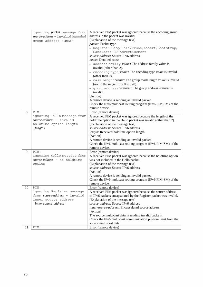
76
ignoring packet message from source-address - invalid encoded group address (cause)
A received PIM packet was ignored because the encoding group address in the packet was invalid. [Explanation of the message text] packet: Packet type • Register-Stop, Join/Prune, Assert, Bootstrap, Candidate-RP-Advertisement
source-address: Source IPv6 address cause: Detailed cause • address family 'value': The address family value is
invalid (other than 2). • encoding type 'value': The encoding type value is invalid
(other than 0). • mask length 'value': The group mask length value is invalid
(not in the range from 8 to 128). • group address 'address': The group address address is
invalid. [Action] A remote device is sending an invalid packet. Check the IPv6 multicast routing program (IPv6 PIM-SM) of the remote device.
8 Error (remote device)
PIM: ignoring Hello message from source-address - invalid holdtime option length (length)
A received PIM packet was ignored because the length of the holdtime option in the Hello packet was invalid (other than 2). [Explanation of the message text] source-address: Source IPv6 address length: Received holdtime option length [Action] A remote device is sending an invalid packet. Check the IPv6 multicast routing program (IPv6 PIM-SM) of the remote device.
9 Error (remote device)
PIM: ignoring Hello message from source-address - no holdtime option
A received PIM packet was ignored because the holdtime option was not included in the Hello packet. [Explanation of the message text] source-address: Source IPv6 address [Action] A remote device is sending an invalid packet. Check the IPv6 multicast routing program (IPv6 PIM-SM) of the remote device.
10 Error (remote device)
PIM: ignoring Register message from source-address - invalid inner source address 'inner-source-address'
A received PIM packet was ignored because the source address of IPv6 packets encapsulated by the Register packet was invalid. [Explanation of the message text] source-address: Source IPv6 address inner-source-address: Encapsulated source address [Action] The source multi-cast data is sending invalid packets. Check the IPv6 multi-cast communication program sent from the source multi-cast data.
11 PIM: Error (remote device)
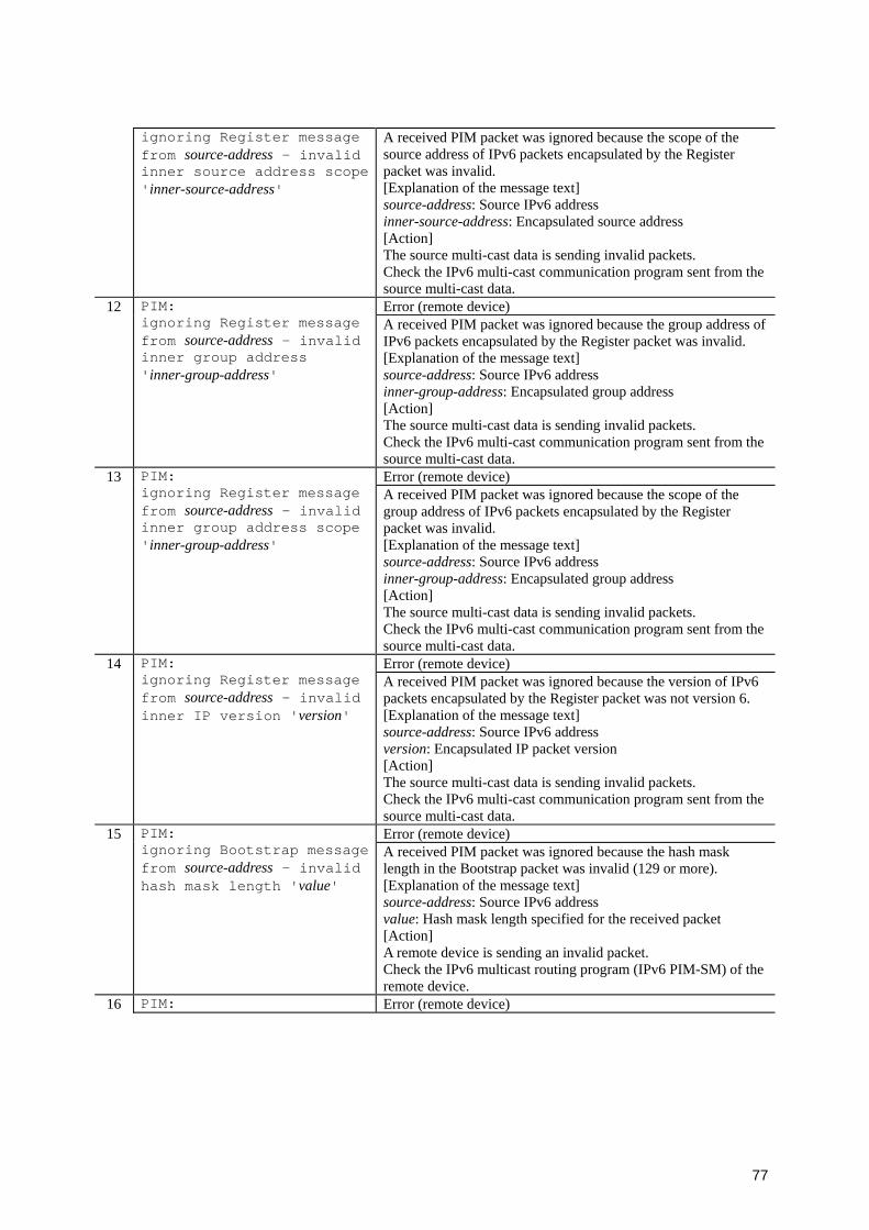
77
ignoring Register message from source-address - invalid inner source address scope 'inner-source-address'
A received PIM packet was ignored because the scope of the source address of IPv6 packets encapsulated by the Register packet was invalid. [Explanation of the message text] source-address: Source IPv6 address inner-source-address: Encapsulated source address [Action] The source multi-cast data is sending invalid packets. Check the IPv6 multi-cast communication program sent from the source multi-cast data.
12 Error (remote device)
PIM: ignoring Register message from source-address - invalid inner group address 'inner-group-address'
A received PIM packet was ignored because the group address of IPv6 packets encapsulated by the Register packet was invalid. [Explanation of the message text] source-address: Source IPv6 address inner-group-address: Encapsulated group address [Action] The source multi-cast data is sending invalid packets. Check the IPv6 multi-cast communication program sent from the source multi-cast data.
13 Error (remote device)
PIM: ignoring Register message from source-address - invalid inner group address scope 'inner-group-address'
A received PIM packet was ignored because the scope of the group address of IPv6 packets encapsulated by the Register packet was invalid. [Explanation of the message text] source-address: Source IPv6 address inner-group-address: Encapsulated group address [Action] The source multi-cast data is sending invalid packets. Check the IPv6 multi-cast communication program sent from the source multi-cast data.
14 Error (remote device)
PIM: ignoring Register message from source-address - invalid inner IP version 'version'
A received PIM packet was ignored because the version of IPv6 packets encapsulated by the Register packet was not version 6. [Explanation of the message text] source-address: Source IPv6 address version: Encapsulated IP packet version [Action] The source multi-cast data is sending invalid packets. Check the IPv6 multi-cast communication program sent from the source multi-cast data.
15 Error (remote device)
PIM: ignoring Bootstrap message from source-address - invalid hash mask length 'value'
A received PIM packet was ignored because the hash mask length in the Bootstrap packet was invalid (129 or more). [Explanation of the message text] source-address: Source IPv6 address value: Hash mask length specified for the received packet [Action] A remote device is sending an invalid packet. Check the IPv6 multicast routing program (IPv6 PIM-SM) of the remote device.
16 PIM: Error (remote device)

78
ignoring Bootstrap message from source-address - invalid BSR address 'IPv6-address'
A received PIM packet was ignored because the BSR address in the Bootstrap packet was invalid. [Explanation of the message text] source-address: Source IPv6 address IPv6-address: BSR address [Action] A remote device is sending an invalid packet. Check the IPv6 multicast routing program (IPv6 PIM-SM) of the remote device.
17 Warning (local device)
PIM: ignoring Bootstrap message from source-address - cannot find a route to the BSR(IPv6-address)
A received PIM packet was ignored because the unicast route to the BSR address in the Bootstrap was not found. [Explanation of the message text] source-address: Source IPv6 address IPv6-address: BSR address [Action] Check whether the route to the BSR address in the Bootstrap packet exists.
18 Error (remote device)
PIM: ignoring Candidate-RP-Advertisement message from source-address - non global address(IPv6-address) as RP
A received PIM packet was ignored because the rendezvous point address included in the Candidate-RP-Advertisement packet was invalid. [Explanation of the message text] source-address: Source IPv6 address IPv6-address: Rendezvous point address [Action] A remote device is sending an invalid packet. Check the IPv6 multicast routing program (IPv6 PIM-SM) of the remote device.
19 Warning (remote device)
PIM: BSR information was changed - lost BSR information
BSR information was cleared because advertisements from the Bootstrap router were lost. [Explanation of the message text] None [Action] Check the reason why advertisements from the Bootstrap router were lost.
20 Event (local device)
PIM: BSR information was changed - new BSR address IPv6-address
BSR address was changed. [Explanation of the message text] IPv6-address: BSR address If the BSR address is this device, (this system) is displayed after the IPv6 address. [Action] None
21 Event (local device)
PIM: Add interface interface-name to the output interface list of (S,G)=(source-address, group-address)
Interface interface-name was added to the output interface list of the multicast routing cache (S, G) (this message is output to syslog only). [Explanation of the message text] interface-name: Interface name source-address: Source IPv6 address group-address: IPv6 group address [Action] None
22 PIM: Event (local device)

79
Delete interface interface-namefrom the output interface list of (S,G)=(source-address, group-address)
Interface interface-name was deleted from the output interface list of the multicast routing cache (S, G) (this message is output to syslog only). [Explanation of the message text] interface-name: Interface name source-address: Source IPv6 address group-address: IPv6 group address [Action] None

80
81
3. Device Failure and Event Information
This chapter describes the contents of device failure and event information. All messages for
device failure and event information are output to the operation terminal window. Depending
on the error severity or event contents, the information is classified into seven event levels,
ranging from E3 to E9. If you specify the event level by using the set logging console
command, you can limit the output of messages to the specified level or lower.
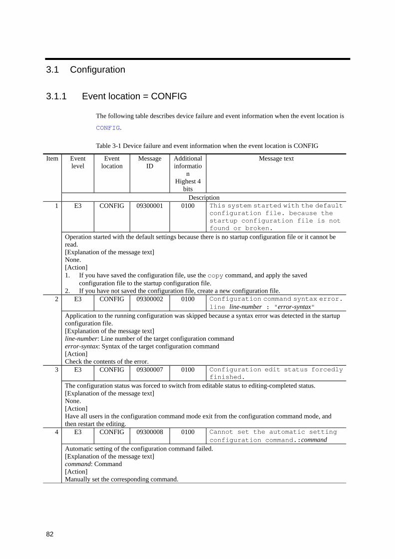
82
3.1 Configuration
3.1.1 Event location = CONFIG
The following table describes device failure and event information when the event location is
CONFIG.
Table 3-1 Device failure and event information when the event location is CONFIG
Event level
Event location
Message ID
Additional informatio
n Highest 4
bits
Message text Item
Description E3 CONFIG 09300001 0100 This system started with the default
configuration file. because the startup configuration file is not found or broken.
1
Operation started with the default settings because there is no startup configuration file or it cannot be read. [Explanation of the message text] None. [Action] 1. If you have saved the configuration file, use the copy command, and apply the saved
configuration file to the startup configuration file. 2. If you have not saved the configuration file, create a new configuration file.
E3 CONFIG 09300002 0100 Configuration command syntax error. line line-number : "error-syntax"
2
Application to the running configuration was skipped because a syntax error was detected in the startup configuration file. [Explanation of the message text] line-number: Line number of the target configuration command error-syntax: Syntax of the target configuration command [Action] Check the contents of the error.
E3 CONFIG 09300007 0100 Configuration edit status forcedly finished.
3
The configuration status was forced to switch from editable status to editing-completed status. [Explanation of the message text] None. [Action] Have all users in the configuration command mode exit from the configuration command mode, and then restart the editing.
E3 CONFIG 09300008 0100 Cannot set the automatic setting configuration command.:command
4
Automatic setting of the configuration command failed. [Explanation of the message text] command: Command [Action] Manually set the corresponding command.

83
E3 CONFIG 09600006 0100 Configuration access management error. processprocess-name:pidprocess-ID:time time
5
The lock was released and the device was automatically recovered because a process was accessing the configuration for a long time. [Explanation of the message text] process-name: Occurrence process name process-ID: Occurrence process ID time: Occurrence time (day-of-the-week month day hour:minutes:seconds year) [Action] None.

84
3.2 Access
3.2.1 Event location = ACCESS
The following table describes device failure and event information when the event location is
ACCESS.
Table 3-2 Device failure and event information when the event location is ACCESS
Event level
Event location
Message ID
Additional
information
Highest 4 bits
Message text Item
Description E3 ACCESS 00000001 0201
0205 Unknown host address IP-address. 1
An attempt to connect via telnet or FTP from IP-address was not permitted. [Explanation of the message text] IP-address: IPv4 address or IPv6 address [Action] 1. There might have been an unauthorized access (an access from a remote host other than one
permitted by the configuration) to this switch. Check the remote host whose IPv4 address or IPv6 address is IP-address.
2. If remote access from IP-address is permitted, the configuration might be incorrect. Check the configuration.
3. If you want to permit remote access from IP-address, specify access permissions for the configuration.
E3 ACCESS 00000002 0201 0205
Login incorrect user-name. 2
An attempt to log in by using the user-name account was made, but login was not allowed. [Explanation of the message text] user-name: User name [Action] 1. There might have been an unauthorized access (failed account or password authentication) to this
switch from a remote host permitted at the console or the configuration. Check the operational status of the remote host that is permitted at the console or the configuration.
2. This log data is collected even when a legitimate user executes an incorrect operation during login. Therefore, even if this log message is collected, the operation of the remote host might be normal.
3. Check if the account was already registered for this switch by using the adduser command. (Confirmation method: Check if the user has a home directory in ls/usr/home/)
E3 ACCESS 00000003 0201 0205
Login refused for too many users logged in.
3
An attempt to connect via telnet was refused because too many users are logged in. [Explanation of the message text] None. [Action] 1. Check the number of users who are currently logged in. 2. If necessary, increase the limit for the number of users who can log in for the configuration.
4 E3 ACCESS 00005002 0200 Login user-name from host (term).
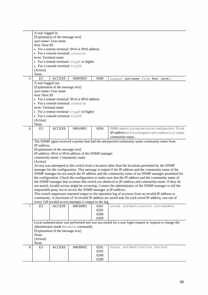
85
A user logged in. [Explanation of the message text] user-name: User name host: Host ID • For a remote terminal: IPv4 or IPv6 address • For a console terminal: console term: Terminal name • For a remote terminal: ttyp0 or higher • For a console terminal: tty00 [Action] None.
E3 ACCESS 00005003 0200 Logout user-name from host (term). 5 A user logged out. [Explanation of the message text] user-name: User name host: Host ID • For a remote terminal: IPv4 or IPv6 address • For a console terminal: console term: Terminal name • For a remote terminal: ttyp0 or higher • For a console terminal: tty00 [Action] None.
E3 ACCESS 00010001 0204 SNMP agent program received packet from IP-addresswith unexpected community name community-name.
6
The SNMP agent received a packet that had the unexpected community name community-name from IP-address. [Explanation of the message text] IP-address: IPv4 or IPv6 address of the SNMP manager community-name: Community name [Action] Access was attempted to this switch from a location other than the locations permitted by the SNMP manager for the configuration. This message is output if the IP address and the community name of the SNMP manager do not match the IP address and the community name of an SNMP manager permitted for the configuration. Check the configuration to make sure that the IP address and the community name of the SNMP manager that accesses this switch are identical to IP-address and community-name. If they do not match, invalid access might be occurring. Contact the administrator of the SNMP manager to tell the responsible party not to access the SNMP manager at IP-address. This switch suppresses repeated output to the operation log of accesses from an invalid IP address or community. A maximum of 16 invalid IP address are saved and, for each saved IP address, one out of every 128 invalid access attempts is output to the log.
E3 ACCESS 00030001 0201 0205 0208 0209
Local authentication succeeded. 7
Local authentication was performed and was successful for a user login request or request to change the administrator mode (enable command). [Explanation of the message text] None. [Action] None.
8 E3 ACCESS 00030002 0201 0205 0208 0209
Local authentication failed.

86
Local authentication was performed but authentication failed for a user login request or request to change the administrator mode (enable command). [Explanation of the message text] None. [Action] 1. An invalid attempt to access this switch might have occurred for a remote host permitted by the
configuration. Check the operational status of the remote host. 2. This log data is collected even when a legitimate user executes an incorrect operation (such as
incorrect password entry) during login. Therefore, even if this log message is collected, the operation of the remote host might be normal.
E3 ACCESS 00030003 0201 0205 0208 0209
RADIUS authentication accepted from host.
9
RADIUS authentication was performed successfully for a user login request or request to change the administrator mode (enable command). [Explanation of the message text] host: IP address or host name of the RADIUS server [Action] None.
E3 ACCESS 00030004 0201 0205 0208 0209
RADIUS authentication rejected from host. "message"
10
RADIUS authentication was attempted, but authentication failed for a user login request or request to change the administrator mode (enable command). [Explanation of the message text] host: IP address or host name of the RADIUS server message: RADIUS server response message [Action] 1. An invalid attempt to access this switch might have occurred for a remote host permitted by the
configuration. Check the operational status of the remote host. 2. This log data is collected even when a legitimate user executes an incorrect operation (such as
incorrect password entry) during login. Therefore, even if this log message is collected, the operation of the remote host might be normal.
3. Check the RADIUS server setting. E3 ACCESS 00030005 0201
0205 0208 0209
RADIUS server (host) didn't response.11
RADIUS authentication was attempted for a user login request or request to change the administrator mode (enable command), but the RADIUS server did not respond. [Explanation of the message text] host: IP address or host name of the RADIUS server [Action] 1. Check the configuration to make sure that the RADIUS server IP address is correct. 2. Check the RADIUS server configuration to make sure that the RADIUS server port number is
correct. 12 E3 ACCESS 00030006 0201
0205 0208 0209
RADIUS server configuration not defined.
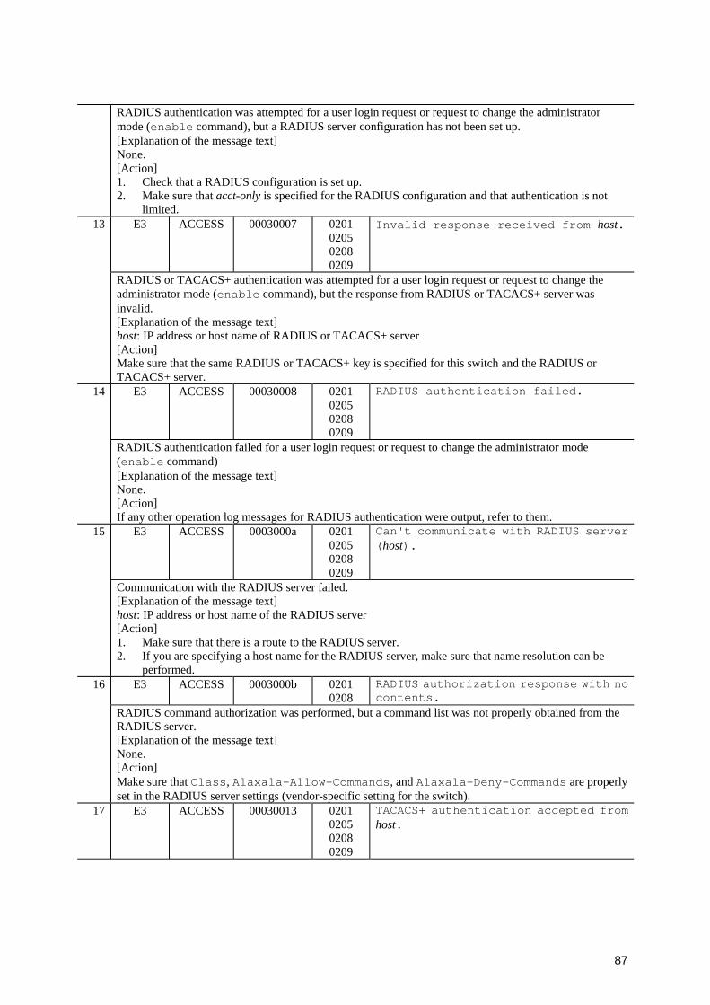
87
RADIUS authentication was attempted for a user login request or request to change the administrator mode (enable command), but a RADIUS server configuration has not been set up. [Explanation of the message text] None. [Action] 1. Check that a RADIUS configuration is set up. 2. Make sure that acct-only is specified for the RADIUS configuration and that authentication is not
limited. E3 ACCESS 00030007 0201
0205 0208 0209
Invalid response received from host.13
RADIUS or TACACS+ authentication was attempted for a user login request or request to change the administrator mode (enable command), but the response from RADIUS or TACACS+ server was invalid. [Explanation of the message text] host: IP address or host name of RADIUS or TACACS+ server [Action] Make sure that the same RADIUS or TACACS+ key is specified for this switch and the RADIUS or TACACS+ server.
E3 ACCESS 00030008 0201 0205 0208 0209
RADIUS authentication failed. 14
RADIUS authentication failed for a user login request or request to change the administrator mode (enable command) [Explanation of the message text] None. [Action] If any other operation log messages for RADIUS authentication were output, refer to them.
E3 ACCESS 0003000a 0201 0205 0208 0209
Can't communicate with RADIUS server (host).
15
Communication with the RADIUS server failed. [Explanation of the message text] host: IP address or host name of the RADIUS server [Action] 1. Make sure that there is a route to the RADIUS server. 2. If you are specifying a host name for the RADIUS server, make sure that name resolution can be
performed. E3 ACCESS 0003000b 0201
0208 RADIUS authorization response with no contents.
16
RADIUS command authorization was performed, but a command list was not properly obtained from the RADIUS server. [Explanation of the message text] None. [Action] Make sure that Class, Alaxala-Allow-Commands, and Alaxala-Deny-Commands are properly set in the RADIUS server settings (vendor-specific setting for the switch).
17 E3 ACCESS 00030013 0201 0205 0208 0209
TACACS+ authentication accepted from host.

88
TACACS+ authentication was successfully performed for a user login request or request to change the administrator mode (enable command). [Explanation of the message text] host: IP address or host name of the TACACS+ server [Action] None.
E3 ACCESS 00030014 0201 0205 0208 0209
TACACS+ authentication rejected from host.
18
TACACS+ authentication was attempted for a user login request or request to change the administrator mode (enable command), but the TACACS+ server denied it. [Explanation of the message text] host: IP address or host name of the TACACS+ server [Action] 1. An invalid attempt to access this switch might have occurred for a remote host permitted by the
configuration. Check the operational status of the remote host. 2. This log data is collected even when a legitimate user executes an incorrect operation (such as
incorrect password entry) during login. Therefore, the operation status of the remote host might be correct, even if this log data is collected.
3. Check the TACACS+ server setting. E3 ACCESS 00030015 0201
0205 0208 0209
TACACS+ server (host) didn't response.19
TACACS+ authentication and command authorization (if there is a command authorization specification in the TACACS+ configuration) were attempted for a user login request or request to change the administrator mode (enable command), but the TACACS+ server did not respond. [Explanation of the message text] host: IP address or host name of the TACACS+ server [Action] Check the configuration to make sure that the TACACS+ server IP address is correct.
E3 ACCESS 00030016 0201 0205 0208 0209
TACACS+ server configuration is not defined.
20
TACACS+ authentication was attempted for a user login request or request to change the administrator mode (enable command), but a TACACS+ server configuration did not exist. [Explanation of the message text] None. [Action] 1. Make sure that a TACACS+ configuration is set up. 2. Make sure that acct-only is specified for the TACACS+ configuration and the authentication is not
limited. E3 ACCESS 00030018 0201
0205 0208 0209
TACACS+ authentication failed. 21
TACACS+ authentication failed for a user login request or request to change the administrator mode (enable command). [Explanation of the message text] None. [Action] If any other operation log messages were output for TACACS+ authentication, refer to them.
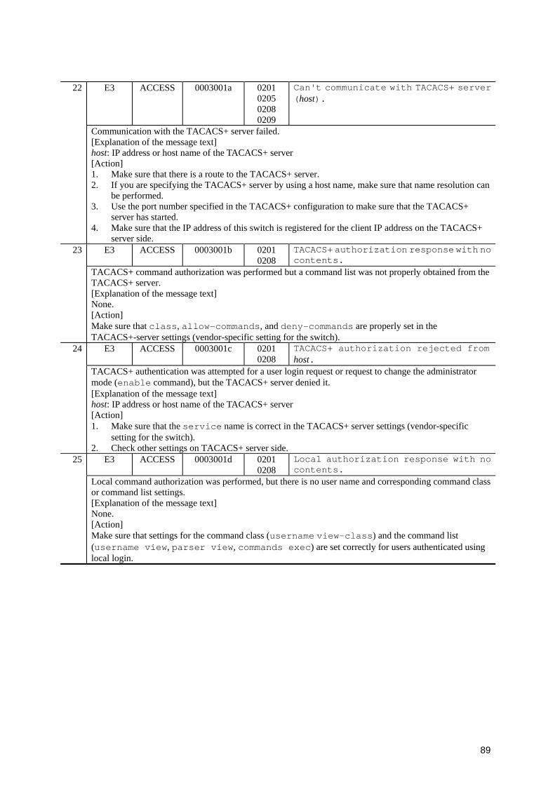
89
E3 ACCESS 0003001a 0201 0205 0208 0209
Can't communicate with TACACS+ server (host).
22
Communication with the TACACS+ server failed. [Explanation of the message text] host: IP address or host name of the TACACS+ server [Action] 1. Make sure that there is a route to the TACACS+ server. 2. If you are specifying the TACACS+ server by using a host name, make sure that name resolution can
be performed. 3. Use the port number specified in the TACACS+ configuration to make sure that the TACACS+
server has started. 4. Make sure that the IP address of this switch is registered for the client IP address on the TACACS+
server side. E3 ACCESS 0003001b 0201
0208 TACACS+ authorization response with no contents.
23
TACACS+ command authorization was performed but a command list was not properly obtained from the TACACS+ server. [Explanation of the message text] None. [Action] Make sure that class, allow-commands, and deny-commands are properly set in the TACACS+-server settings (vendor-specific setting for the switch).
E3 ACCESS 0003001c 0201 0208
TACACS+ authorization rejected from host.
24
TACACS+ authentication was attempted for a user login request or request to change the administrator mode (enable command), but the TACACS+ server denied it. [Explanation of the message text] host: IP address or host name of the TACACS+ server [Action] 1. Make sure that the service name is correct in the TACACS+ server settings (vendor-specific
setting for the switch). 2. Check other settings on TACACS+ server side.
E3 ACCESS 0003001d 0201 0208
Local authorization response with no contents.
25
Local command authorization was performed, but there is no user name and corresponding command class or command list settings. [Explanation of the message text] None. [Action] Make sure that settings for the command class (username view-class) and the command list (username view, parser view, commands exec) are set correctly for users authenticated using local login.

90
3.3 Protocol
3.3.1 Event location = IP
The following table describes device failure and event information when the event location is
IP.
3-3 Device failure and event information when the event location is IP
Event level
Event location
Message ID
Additional informatio
n Highest 4
bits
Message text Item
Description E4 IP 26000001 0600 The ARP entry can't be registered
at hardware tables. (IPv4-address) 1
An ARP entry cannot be registered in the hardware tables. [Explanation of the message text] IPv4-address: IPv4 address of the ARP entry that cannot be registered in the hardware tables [Action] Review the capacity limitations. However, depending on specifications of the cache applied to the hardware, certain IP address combinations do not allow the setting to the maximum of the capacity limit.
E4 IP 26000002 0600 The ARP entry can't be deleted from hardware tables.
2
An ARP entry cannot be deleted from the hardware tables. [Explanation of the message text] None. [Action] Replace the device.
E4 IP 26000003 0600 The NDP entry can't be registered at hardware tables. (IPv6-address)
3
An NDP entry cannot be registered in the hardware tables. [Explanation of the message text] IPv6-address: IPv6 address of NDP entry that cannot be registered in the hardware tables [Action] Review the capacity limitations. However, depending on specifications of the cache applied to the hardware, certain IPv6 address combinations do not allow the setting to the maximum of the capacity limit.
E4 IP 26000004 0600 The NDP entry can't be deleted from hardware tables.
4
An NDP entry cannot be deleted from the hardware tables. [Explanation of the message text] None. [Action] Replace the device.
5 E4 IP 26000005 0600 IPv4 unicast routing information can't be registered at hardware tables. (IPv4-prefix/masklen)

91
An IPv4 unicast routing table entry cannot be registered in the hardware tables. [Explanation of the message text] IPv4-prefix: IPv4 unicast routing table entry that cannot be registered in the hardware tables masklen: Subnet mask length of the above IPv4 unicast routing table entry [Action] Review the capacity limitations. However, depending on specifications of the cache applied to the hardware, certain IP addresses do not allow the setting to the maximum of the capacity limit.
E4 IP 26000006 0600 IPv4 unicast routing information can't be deleted from hardware tables.
6
An IPv4 unicast routing table entry cannot be deleted from the hardware tables. [Explanation of the message text] None. [Action] Replace the device.
E4 IP 26000007 0600 IPv4 multicast routing information can't be registered at hardware tables. (Source:IPv4-address Group:IPv4-address)
7
An IPv4 multicast routing table entry cannot be registered in the hardware tables. [Explanation of the message text] IPv4-address: Source IPv4 address and group address of the IPv4 multicast routing table entry that cannot be registered in the hardware tables [Action] Review the capacity limitations. However, depending on specifications of the cache applied to the hardware, certain IP addresses do not allow the setting to the maximum of the capacity limit.
E4 IP 26000008 0600 IPv4 multicast routing information can't be deleted from hardware tables.
8
An IPv4 multicast routing table entry cannot be deleted from the hardware tables. [Explanation of the message text] None. [Action] Replace the device.
E4 IP 26000009 0600 IPv6 unicast routing information can't be registered at hardware tables. (IPv6-prefix/prefixlen)
9
An IPv6 unicast routing table entry cannot be registered in the hardware tables. [Explanation of the message text] IPv6-prefix: IPv6 unicast routing table entry that cannot be registered in the hardware tables prefixlen: Prefix length of the above IPv6 unicast routing table entry [Action] Review the capacity limitations. However, depending on specifications of the cache applied to the hardware, certain IPv6 addresses do not allow the setting to the maximum of the capacity limit.
E4 IP 2600000a 0600 IPv6 unicast routing information can't be deleted from hardware tables.
10
An IPv6 unicast routing table entry cannot be deleted from the hardware tables. [Explanation of the message text] None. [Action] Replace the device.
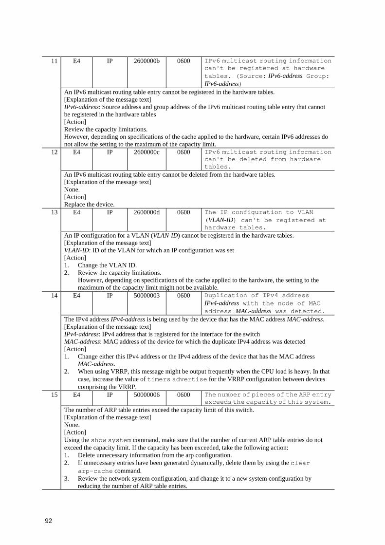
92
E4 IP 2600000b 0600 IPv6 multicast routing information can't be registered at hardware tables. (Source: IPv6-address Group: IPv6-address)
11
An IPv6 multicast routing table entry cannot be registered in the hardware tables. [Explanation of the message text] IPv6-address: Source address and group address of the IPv6 multicast routing table entry that cannot be registered in the hardware tables [Action] Review the capacity limitations. However, depending on specifications of the cache applied to the hardware, certain IPv6 addresses do not allow the setting to the maximum of the capacity limit.
E4 IP 2600000c 0600 IPv6 multicast routing information can't be deleted from hardware tables.
12
An IPv6 multicast routing table entry cannot be deleted from the hardware tables. [Explanation of the message text] None. [Action] Replace the device.
E4 IP 2600000d 0600 The IP configuration to VLAN (VLAN-ID) can't be registered at hardware tables.
13
An IP configuration for a VLAN (VLAN-ID) cannot be registered in the hardware tables. [Explanation of the message text] VLAN-ID: ID of the VLAN for which an IP configuration was set [Action] 1. Change the VLAN ID. 2. Review the capacity limitations.
However, depending on specifications of the cache applied to the hardware, the setting to the maximum of the capacity limit might not be available.
E4 IP 50000003 0600 Duplication of IPv4 address IPv4-address with the node of MAC address MAC-address was detected.
14
The IPv4 address IPv4-address is being used by the device that has the MAC address MAC-address. [Explanation of the message text] IPv4-address: IPv4 address that is registered for the interface for the switch MAC-address: MAC address of the device for which the duplicate IPv4 address was detected [Action] 1. Change either this IPv4 address or the IPv4 address of the device that has the MAC address
MAC-address. 2. When using VRRP, this message might be output frequently when the CPU load is heavy. In that
case, increase the value of timers advertise for the VRRP configuration between devices comprising the VRRP.
E4 IP 50000006 0600 The number of pieces of the ARP entry exceeds the capacity of this system.
15
The number of ARP table entries exceed the capacity limit of this switch. [Explanation of the message text] None. [Action] Using the show system command, make sure that the number of current ARP table entries do not exceed the capacity limit. If the capacity has been exceeded, take the following action: 1. Delete unnecessary information from the arp configuration. 2. If unnecessary entries have been generated dynamically, delete them by using the clear
arp-cache command. 3. Review the network system configuration, and change it to a new system configuration by
reducing the number of ARP table entries.
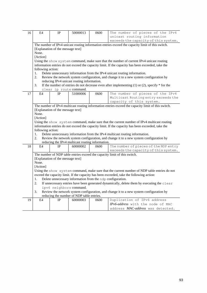
93
E4 IP 50000013 0600 The number of pieces of the IPv4 unicast routing information exceeds the capacity of this system.
16
The number of IPv4 unicast routing information entries exceed the capacity limit of this switch. [Explanation of the message text] None. [Action] Using the show system command, make sure that the number of current IPv4 unicast routing information entries do not exceed the capacity limit. If the capacity has been exceeded, take the following action: 1. Delete unnecessary information from the IPv4 unicast routing information. 2. Review the network system configuration, and change it to a new system configuration by
reducing IPv4 unicast routing information. 3. If the number of entries do not decrease even after implementing (1) or (2), specify * for the
clear ip route command. E4 IP 51000006 0600 The number of pieces of the IPv4
Multicast Routing entry exceeds the capacity of this system.
17
The number of IPv4 multicast routing information entries exceed the capacity limit of this switch. [Explanation of the message text] None. [Action] Using the show system command, make sure that the current number of IPv4 multicast routing information entries do not exceed the capacity limit. If the capacity has been exceeded, take the following action: 1. Delete unnecessary information from the IPv4 multicast routing information. 2. Review the network system configuration, and change it to a new system configuration by
reducing the IPv4 multicast routing information. E4 IP 60000002 0600 The number of pieces of the NDP entry
exceeds the capacity of this system.18
The number of NDP table entries exceed the capacity limit of this switch. [Explanation of the message text] None. [Action] Using the show system command, make sure that the current number of NDP table entries do not exceed the capacity limit. If the capacity has been exceeded, take the following action: 1. Delete unnecessary information from the ndp configuration. 2. If unnecessary entries have been generated dynamically, delete them by executing the clear
ipv6 neighbors command. 3. Review the network system configuration, and change it to a new system configuration by
reducing the number of NDP table entries. 19 E4 IP 60000003 0600 Duplication of IPv6 address
IPv6-address with the node of MAC address MAC-address was detected.
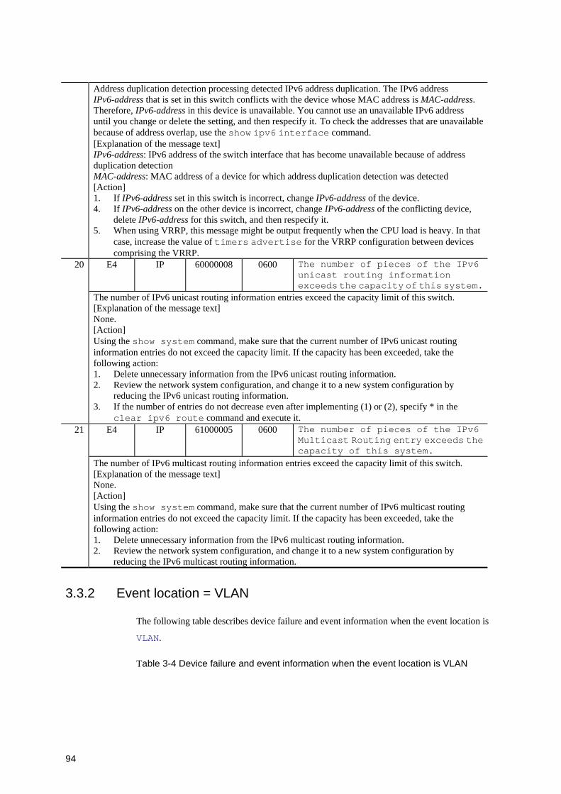
94
Address duplication detection processing detected IPv6 address duplication. The IPv6 address IPv6-address that is set in this switch conflicts with the device whose MAC address is MAC-address. Therefore, IPv6-address in this device is unavailable. You cannot use an unavailable IPv6 address until you change or delete the setting, and then respecify it. To check the addresses that are unavailable because of address overlap, use the show ipv6 interface command. [Explanation of the message text] IPv6-address: IPv6 address of the switch interface that has become unavailable because of address duplication detection MAC-address: MAC address of a device for which address duplication detection was detected [Action] 1. If IPv6-address set in this switch is incorrect, change IPv6-address of the device. 4. If IPv6-address on the other device is incorrect, change IPv6-address of the conflicting device,
delete IPv6-address for this switch, and then respecify it. 5. When using VRRP, this message might be output frequently when the CPU load is heavy. In that
case, increase the value of timers advertise for the VRRP configuration between devices comprising the VRRP.
E4 IP 60000008 0600 The number of pieces of the IPv6 unicast routing information exceeds the capacity of this system.
20
The number of IPv6 unicast routing information entries exceed the capacity limit of this switch. [Explanation of the message text] None. [Action] Using the show system command, make sure that the current number of IPv6 unicast routing information entries do not exceed the capacity limit. If the capacity has been exceeded, take the following action: 1. Delete unnecessary information from the IPv6 unicast routing information. 2. Review the network system configuration, and change it to a new system configuration by
reducing the IPv6 unicast routing information. 3. If the number of entries do not decrease even after implementing (1) or (2), specify * in the
clear ipv6 route command and execute it. E4 IP 61000005 0600 The number of pieces of the IPv6
Multicast Routing entry exceeds the capacity of this system.
21
The number of IPv6 multicast routing information entries exceed the capacity limit of this switch. [Explanation of the message text] None. [Action] Using the show system command, make sure that the current number of IPv6 multicast routing information entries do not exceed the capacity limit. If the capacity has been exceeded, take the following action: 1. Delete unnecessary information from the IPv6 multicast routing information. 2. Review the network system configuration, and change it to a new system configuration by
reducing the IPv6 multicast routing information.
3.3.2 Event location = VLAN
The following table describes device failure and event information when the event location is
VLAN.
Table 3-4 Device failure and event information when the event location is VLAN

95
Event level
Event location
Message ID
Additional informatio
n Highest 4
bits
Message text Item
Description E3 VLAN 20110002 0700 STP(mode): This bridge becomes the Root
Bridge. 1
The switch has become the root bridge. [Explanation of the message text] mode: Spanning tree type • single: Single spanning tree • PVST+:VLAN VLAN-ID: PVST+ spanning tree and VLAN ID [Action] None.
E3 VLAN 20110003 0700 STP(mode): This bridge becomes the Designated Bridge.
2
The switch has become the designated bridge. [Explanation of the message text] mode: Spanning tree type • single: Single spanning tree • PVST+:VLAN VLAN-ID: PVST+ spanning tree and VLAN ID [Action] None.
E3 VLAN 20110006 0700 STP(mode): Topology change detected -BPDU Timeout detected on the root port(NIF-number / port-number).
3
A BPDU timeout was detected on the root port. [Explanation of the message text] mode: Spanning tree type • single: Single spanning tree • PVST+:VLAN VLAN-ID: PVST+ spanning tree and VLAN ID • CIST: Multiple spanning tree (CIST) • MST Instance MST-instance-ID: Multiple spanning tree (MSTI) and MST instance ID NIF-number/port-number: NIF number / port number [Action] Check the line status.
E3 VLAN 20110007 0700 STP(mode): Topology change detected -Topology Change Notification BPDU received on the port(NIF-number / port-number).
4
A topology change BPDU has been received. [Explanation of the message text] mode: Spanning tree type • single: Single spanning tree • PVST+:VLAN VLAN-ID: PVST+ spanning tree and VLAN ID • MST: Multiple spanning tree NIF-number/port-number: NIF number / port number [Action] Check the line status.
5 E3 VLAN 20110011 0700 STP(mode): Spanning Tree Protocol enabled - BPDU received on the Port Fast(NIF-number / port-number).
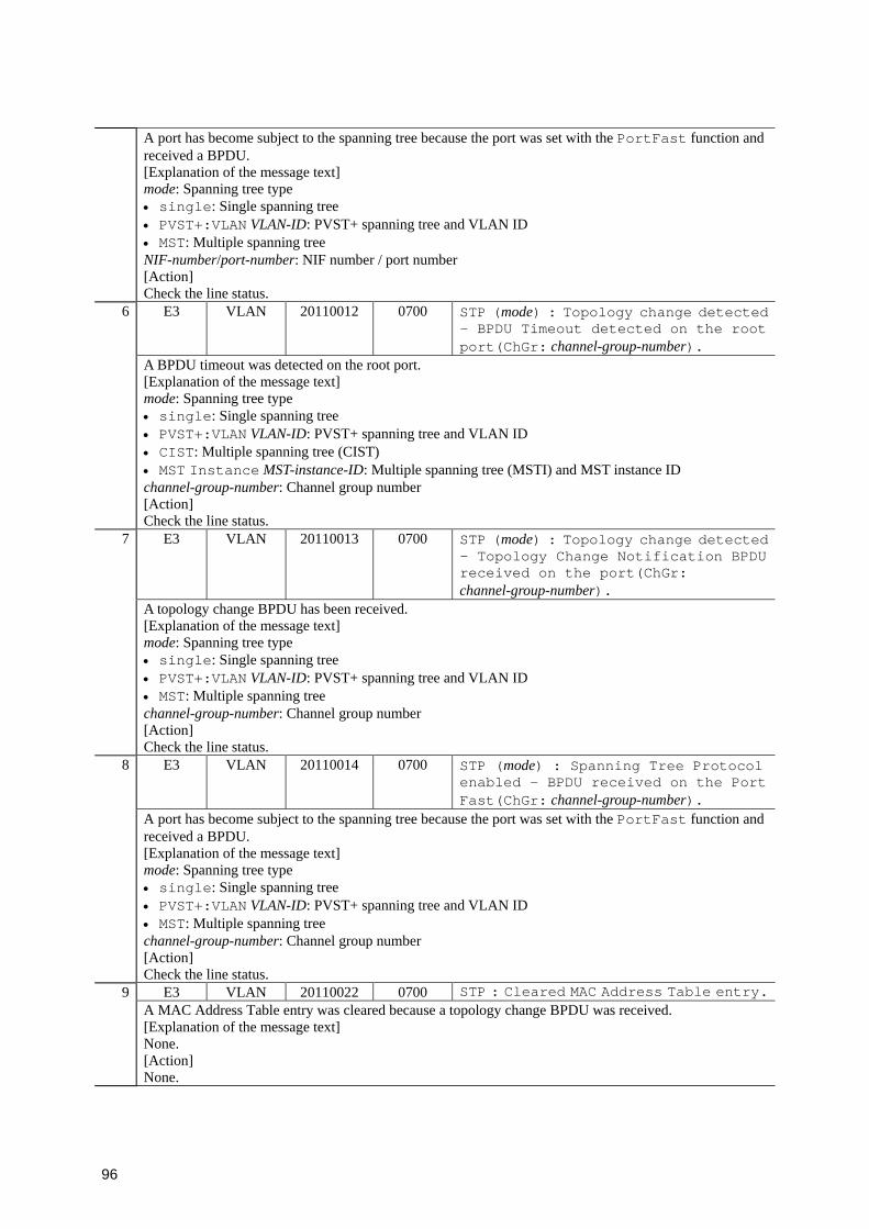
96
A port has become subject to the spanning tree because the port was set with the PortFast function and received a BPDU. [Explanation of the message text] mode: Spanning tree type • single: Single spanning tree • PVST+:VLAN VLAN-ID: PVST+ spanning tree and VLAN ID • MST: Multiple spanning tree NIF-number/port-number: NIF number / port number [Action] Check the line status.
E3 VLAN 20110012 0700 STP (mode) : Topology change detected - BPDU Timeout detected on the root port(ChGr: channel-group-number).
6
A BPDU timeout was detected on the root port. [Explanation of the message text] mode: Spanning tree type • single: Single spanning tree • PVST+:VLAN VLAN-ID: PVST+ spanning tree and VLAN ID • CIST: Multiple spanning tree (CIST) • MST Instance MST-instance-ID: Multiple spanning tree (MSTI) and MST instance ID channel-group-number: Channel group number [Action] Check the line status.
E3 VLAN 20110013 0700 STP (mode) : Topology change detected - Topology Change Notification BPDU received on the port(ChGr: channel-group-number).
7
A topology change BPDU has been received. [Explanation of the message text] mode: Spanning tree type • single: Single spanning tree • PVST+:VLAN VLAN-ID: PVST+ spanning tree and VLAN ID • MST: Multiple spanning tree channel-group-number: Channel group number [Action] Check the line status.
E3 VLAN 20110014 0700 STP (mode) : Spanning Tree Protocol enabled - BPDU received on the Port Fast(ChGr: channel-group-number).
8
A port has become subject to the spanning tree because the port was set with the PortFast function and received a BPDU. [Explanation of the message text] mode: Spanning tree type • single: Single spanning tree • PVST+:VLAN VLAN-ID: PVST+ spanning tree and VLAN ID • MST: Multiple spanning tree channel-group-number: Channel group number [Action] Check the line status.
E3 VLAN 20110022 0700 STP : Cleared MAC Address Table entry.9 A MAC Address Table entry was cleared because a topology change BPDU was received. [Explanation of the message text] None. [Action] None.
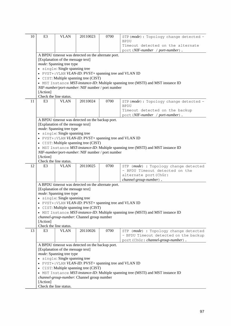
97
E3 VLAN 20110023 0700 STP(mode): Topology change detected -BPDU Timeout detected on the alternate port(NIF-number / port-number).
10
A BPDU timeout was detected on the alternate port. [Explanation of the message text] mode: Spanning tree type • single: Single spanning tree • PVST+:VLAN VLAN-ID: PVST+ spanning tree and VLAN ID • CIST: Multiple spanning tree (CIST) • MST Instance MST-instance-ID: Multiple spanning tree (MSTI) and MST instance ID NIF-number/port-number: NIF number / port number [Action] Check the line status.
E3 VLAN 20110024 0700 STP(mode): Topology change detected -BPDU Timeout detected on the backup port(NIF-number / port-number).
11
A BPDU timeout was detected on the backup port. [Explanation of the message text] mode: Spanning tree type • single: Single spanning tree • PVST+:VLAN VLAN-ID: PVST+ spanning tree and VLAN ID • CIST: Multiple spanning tree (CIST) • MST Instance MST-instance-ID: Multiple spanning tree (MSTI) and MST instance ID NIF-number/port-number: NIF number / port number [Action] Check the line status.
E3 VLAN 20110025 0700 STP (mode) : Topology change detected - BPDU Timeout detected on the alternate port(ChGr: channel-group-number).
12
A BPDU timeout was detected on the alternate port. [Explanation of the message text] mode: Spanning tree type • single: Single spanning tree • PVST+:VLAN VLAN-ID: PVST+ spanning tree and VLAN ID • CIST: Multiple spanning tree (CIST) • MST Instance MST-instance-ID: Multiple spanning tree (MSTI) and MST instance ID channel-group-number: Channel group number [Action] Check the line status.
E3 VLAN 20110026 0700 STP (mode) : Topology change detected - BPDU Timeout detected on the backup port(ChGr: channel-group-number).
13
A BPDU timeout was detected on the backup port. [Explanation of the message text] mode: Spanning tree type • single: Single spanning tree • PVST+:VLAN VLAN-ID: PVST+ spanning tree and VLAN ID • CIST: Multiple spanning tree (CIST) • MST Instance MST-instance-ID: Multiple spanning tree (MSTI) and MST instance ID channel-group-number: Channel group number [Action] Check the line status.

98
E3 VLAN 20110027 0700 STP(MST): This bridge becomes the CIST Root Bridge.
14
The switch has become the CIST root bridge. [Explanation of the message text] None. [Action] None.
E3 VLAN 20110028 0700 STP(CIST): This bridge becomes the CIST Regional Root Bridge.
15
The switch has become the CIST regional root bridge. [Explanation of the message text] None. [Action] None.
E3 VLAN 20110029 0700 STP(MST Instance MST-instance-ID): This bridge becomes the MSTI Regional Root Bridge.
16
The switch has become the MSTI regional root bridge. [Explanation of the message text] MST-instance-ID: MST instance ID [Action] None.
E3 VLAN 20110031 0700 STP(CIST): This bridge becomes the CIST Regional Designated Bridge.
17
The switch has become the CIST regional designated bridge. [Explanation of the message text] None. [Action] None.
E3 VLAN 20110032 0700 STP(MST Instance MST-instance-ID): This bridge becomes the MSTI Regional Designated Bridge.
18
The switch has become the MSTI regional designated bridge. [Explanation of the message text] MST-instance-ID: MST instance ID [Action] None.
E3 VLAN 21100001 0700 IGMP snooping: IGMP querier changed on VLAN VLAN-ID - lost IGMP querier address IPv4-address.
19
An advertisement (IGMPQuery) from the IGMP querier IPv4-address on a VLAN (VLAN-ID) has disappeared. The IGMP querier information is deleted. The availability of the IPv4 multicast group member (recipient host) cannot be checked, and IPv4 multicast data forwarding is not properly executed. [Explanation of the message text] VLAN-ID: VLAN ID IPv4-address: IPv4 address [Action] 1. Check the connection with the IGMP querier IPv4-address. 2. Check if the GMP querier change message (message ID is 21100002) was output. 3. If the connection with the IGMP querier cannot be checked, execute the configuration command ip
igmp snooping querier to enable the IGMP querier function of the switch. 20 E3 VLAN 21100002 0700 IGMP snooping: IGMP querier changed on
VLAN VLAN-ID - new IGMP querier address IPv4-address.
99
A IGMP querier was changed to IPv4-address because a new IGMP querier was identified on the VLAN (VLAN-ID). [Explanation of the message text] VLAN-ID: VLAN ID IPv4-address: IPv4 address [Action] None.
E3 VLAN 21100003 0700 IGMP snooping: IPv4 address not defined on VLAN VLAN-ID,IGMP querier function stopped.
21
A IGMP querier on the VLAN (VLAN-ID) was stopped because the IPv4 address is not set. [Explanation of the message text] VLAN-ID: VLAN ID [Action] 1. Set an IPv4 addresses for the appropriate VLAN. 2. Execute the show igmp-snooping command to check that the IPv4 address set for the
appropriate VLAN is displayed. E3 VLAN 21100004 0700 IGMP snooping:The number of the IGMP
snooping entry exceeded the capacity of this system.
22
The number of learn entries used in IGMP snooping exceeds the capacity limit (maximum: 500) of the switch. [Explanation of the message text] None. [Action] The number of entries exceeds the capacity limit. Review the system configuration and settings so that you can reduce the number of entries.
E3 VLAN 20110042 0700 STP (mode) : Topology change detected - BPDU Timeout detected on the root port(VLID: link-ID).
23
A BPDU timeout was detected on the root port. [Explanation of the message text] mode: Spanning tree type • single: Single spanning tree • PVST+:VLAN VLAN-ID: PVST+ spanning tree and VLAN ID • CIST: Multiple spanning tree (CIST) • MST Instance MST-instance-ID: Multiple spanning tree (MSTI) and MST instance ID link-ID: Virtual link ID [Action] Check the line status.
E3 VLAN 20110043 0700 STP (mode) : Topology change detected - Topology Change Notification BPDU received on the port(VLID: link-ID).
24
A topology change BPDU has been received. [Explanation of the message text] mode: Spanning tree type • single: Single spanning tree • PVST+:VLAN VLAN-ID: PVST+ spanning tree and VLAN ID • CIST: Multiple spanning tree (CIST) • MST Instance MST-instance-ID: Multiple spanning tree (MSTI) and MST instance ID link-ID: Virtual link ID [Action] Check the line status.
25 E3 VLAN 20110044 0700 STP (mode) : Topology change detected - BPDU Timeout detected on the alternate port(VLID: link-ID).
100
A BPDU timeout was detected on the alternate port. [Explanation of the message text] mode: Spanning tree type • single: Single spanning tree • PVST+:VLAN VLAN-ID: PVST+ spanning tree and VLAN ID • CIST: Multiple spanning tree (CIST) • MST Instance MST-instance-ID: Multiple spanning tree (MSTI) and MST instance ID link-ID: Virtual link ID [Action] Check the line status.
E3 VLAN 20110045 0700 STP (mode) : Topology change detected - BPDU Timeout detected on the backup port(VLID: link-ID).
26
A BPDU timeout was detected on the backup port. [Explanation of the message text] mode: Spanning tree type • single: Single spanning tree • PVST+:VLAN VLAN-ID: PVST+ spanning tree and VLAN ID • CIST: Multiple spanning tree (CIST) • MST Instance MST-instance-ID: Multiple spanning tree (MSTI) and MST instance ID link-ID: Virtual link ID [Action] Check the line status.
E3 VLAN 20130019 0700 MAC Address Table entry cleared, because flush request received on port port-list, Source MAC address MAC-address.
27
The MAC address table was cleared because a Flush Request frame was received. [Explanation of the message text] port-list: Port range MAC-address: Device MAC address of the frame-sending source [Action] None.
E3 VLAN 21200001 0700 MLD snooping: MLD querier changed on VLAN VLAN-ID - lost MLD querier address IPv6-address.
28
The MLD querier information was deleted because an advertisement (MLD Query) from the MLD querier IPv6-address on a VLAN (VLAN-ID) disappeared. The IPv6 multicast data will not be properly relayed because the existence of the IPv6 multicast group listener (recipient host) cannot be checked. [Explanation of the message text] VLAN-ID: VLAN ID IPv6-address: IPv6 address [Action] 1. Check the connection with the MLD querier at IPv6-address. 2. Check if the MLD querier change message (message ID is 21200002) was output. 3. If the connection with the MLD querier cannot be checked, execute the configuration command
ipv6 mld snooping querier to enable the MLD querier function of the switch. E3 VLAN 21200002 0700 MLD snooping: MLD querier changed on
VLAN VLAN-ID - new MLD querier address IPv6-address.
29
The MLD querier was changed to IPv6-address because a new MLD querier was identified on the VLAN (VLAN-ID). [Explanation of the message text] VLAN-ID: VLAN ID IPv6-address: IPv6 address [Action] None.
101
E3 VLAN 21200003 0700 MLD snooping: IPv6 address not defined on VLAN VLAN-ID, MLD querier function stopped.
30
The MLD querier on VLAN (VLAN-ID) was stopped because the IPv6 address was not set. [Explanation of the message text] VLAN-ID: VLAN ID [Action] 1. Set the IPv6 address for the appropriate VLAN. 2. Execute the show mld-snooping command to check that the IPv6 address set for the appropriate
VLAN is displayed. E3 VLAN 21200004 0700 MLD snooping:The number of the MLD
snooping entry exceeded the capacity of this system.
31
The number of learn entries used in MLD snooping exceeds the capacity limit (maximum: 500) of the switch. [Explanation of the message text] None. [Action] The number of entries exceeds the capacity limit. Review the system configuration and setting so that you can reduce the number of entries.
E3 VLAN 2510001b 0700 Sum of number of VLAN on ports exceeded capacity.
32
The total number of VLANs for each port exceed the capacity limit. [Explanation of the message text] None. [Action] Execute any of the following measures: • Use the copy command to apply the configuration file, with the total number of VLANs for each port
being within the capacity limit, to the running-config file. • Change the total number of VLANs to within the capacity limit, and execute the restart vlan
command. • Change the total number of VLANs to within the capacity limit, and restart the switch.
E4 VLAN 20110008 0700 STP(mode): Port status becomes Forwarding on the port(NIF-number / port-number).
33
The port was placed in the forwarding status. [Explanation of the message text] mode: Spanning tree type • single: Single spanning tree • PVST+:VLAN VLAN-ID: PVST+ spanning tree and VLAN ID • CIST: Multiple spanning tree (CIST) • MST Instance MST-instance-ID: Multiple spanning tree (MSTI) and MST instance ID NIF-number/port-number: NIF number / port number [Action] None.
34 E4 VLAN 20110009 0700 STP(mode): Port status becomes Blocking on the port(NIF-number / port-number).

102
The port was placed in the blocking status. [Explanation of the message text] mode: Spanning tree type • single: Single spanning tree • PVST+:VLAN VLAN-ID: PVST+ spanning tree and VLAN ID • CIST: Multiple spanning tree (CIST) • MST Instance MST-instance-ID: Multiple spanning tree (MSTI) and MST instance ID NIF-number/port-number: NIF number / port number [Action] None.
E4 VLAN 20110010 0700 STP(mode): Port status becomes Down-BPDU received on the BPDU GUARD port(NIF-number / port-number).
35
A port was placed in the down status because it was set with the BPDU guard function and received a BPDU. [Explanation of the message text] mode: Spanning tree type • single: Single spanning tree • PVST+:VLAN VLAN-ID: PVST+ spanning tree and VLAN ID • MST: Multiple spanning tree NIF-number/port-number: NIF number / port number [Action] Check the line status.
E4 VLAN 20110015 0700 STP (mode) : Port status becomes Forwarding on the port(ChGr: channel-group-number).
36
The port was placed in the forwarding status. [Explanation of the message text] mode: Spanning tree type • single: Single spanning tree • PVST+:VLAN VLAN-ID: PVST+ spanning tree and VLAN ID • CIST: Multiple spanning tree (CIST) • MST Instance MST-instance-ID: Multiple spanning tree (MSTI) and MST instance ID channel-group-number: Channel group number [Action] None.
E4 VLAN 20110016 0700 STP (mode) : Port status becomes Blocking on the port(ChGr: channel-group-number).
37
The port was placed in the blocking status. [Explanation of the message text] mode: Spanning tree type • single: Single spanning tree • PVST+:VLAN VLAN-ID: PVST+ spanning tree and VLAN ID • CIST: Multiple spanning tree (CIST) • MST Instance MST-instance-ID: Multiple spanning tree (MSTI) and MST instance ID channel-group-number: Channel group number [Action] None.
38 E4 VLAN 20110017 0700 STP (mode) : Port status becomes Down-BPDU received on the BPDU GUARD port(ChGr: channel-group-number).
103
A port was placed in the down status because it was set with the BPDU guard function and received a BPDU. [Explanation of the message text] mode: Spanning tree type • single: Single spanning tree • PVST+:VLAN VLAN-ID: PVST+ spanning tree and VLAN ID • MST: Multiple spanning tree channel-group-number: Channel group number [Action] Check the line status.
E4 VLAN 20110037 0700 STP (mode) : Port status becomes Blocking on the port(NIF-number / port-number), because IEEE802.1Q Tagged BPDU was received from the port which is not trunk port.
39
Even though there was a setting (using an Untagged frame) for an access port, protocol port, or MAC port, the switch received a BPDU with an IEEE802.1Q tag attached. Because of this, the port was placed in the Blocking status. [Explanation of the message text] mode: Spanning tree type • PVST+:VLAN VLAN-ID: PVST+ spanning tree and VLAN ID NIF-number/port-number: NIF number / port number [Action] Check the settings of the remote device.
E4 VLAN 20110038 0700 STP (mode) : Port status becomes Blocking on the port(ChGr: channel-group-number), because IEEE802.1Q Tagged BPDU was received from the port which is not trunk port.
40
Even though there was a setting (using an Untagged frame) for an access port, protocol port, or MAC port, the switch received a BPDU with an IEEE802.1Q tag attached. Because of this, the port was placed in the Blocking status. [Explanation of the message text] mode: Spanning tree type • PVST+:VLAN VLAN-ID: PVST+ spanning tree and VLAN ID channel-group-number: Channel group number [Action] Check the settings of the remote device.
E4 VLAN 20110039 0700 STP : Exceeded the number of the maximum spanning tree.
41
The number of trees exceed the maximum capacity of the spanning tree. No more trees can be added. [Explanation of the message text] None. [Action] Either review the network configuration, or use a single spanning tree or a multiple spanning tree.
42 E4 VLAN 20110040 0700 STP(mode): Port status becomes Blocking - BPDU that priority is high was received on the ROOT GUARD port(NIF-number / port-number).
104
A port was placed in the Blocking status because it was set with the route-guard function and received a high-priority BPDU. [Explanation of the message text] mode: Spanning tree type • single: Single spanning tree • PVST+:VLAN VLAN-ID: PVST+ spanning tree and VLAN ID • CIST: Multiple spanning tree (CIST) • MST Instance MST-instance-ID: Multiple spanning tree (MSTI) and MST instance ID NIF-number/port-number: NIF number / port number [Action] Check the settings of the remote device.
E4 VLAN 20110041 0700 STP(mode): Port status becomes Blocking - BPDU that priority is high was received on the ROOT GUARD port(ChGr: channel-group-number).
43
A port was placed in the Blocking status because it was set with the route-guard function and received a high-priority BPDU. [Explanation of the message text] mode: Spanning tree type • single: Single spanning tree • PVST+:VLAN VLAN-ID: PVST+ spanning tree and VLAN ID • CIST: Multiple spanning tree (CIST) • MST Instance MST-instance-ID: Multiple spanning tree (MSTI) and MST instance ID channel-group-number: Channel group number [Action] Check the settings of the remote device.
E4 VLAN 20110047 0700 STP (mode) : Port status becomes Forwarding on the port(VLID: link-ID).
44
The port was placed in the forwarding status. [Explanation of the message text] mode: Spanning tree type • single: Single spanning tree • PVST+:VLAN VLAN-ID: PVST+ spanning tree and VLAN ID • CIST: Multiple spanning tree (CIST) • MST Instance MST-instance-ID: Multiple spanning tree (MSTI) and MST instance ID link-ID: Virtual link ID [Action] None.
E4 VLAN 20110048 0700 STP (mode) : Port status becomes Blocking on the port(VLID: link-ID).
45
The port was placed in the blocking status. [Explanation of the message text] mode: Spanning tree type • single: Single spanning tree • PVST+:VLAN VLAN-ID: PVST+ spanning tree and VLAN ID • CIST: Multiple spanning tree (CIST) • MST Instance MST-instance-ID: Multiple spanning tree (MSTI) and MST instance ID link-ID: Virtual link ID [Action] None.
46 E4 VLAN 21100005 0700 The IGMP snooping entry can't be registered at hardware tables(VLAN: VLAN-ID MAC address: MAC-address).
105
An IGMP snooping entry cannot be set in a hardware table. [Explanation of the message text] VLAN-ID: VLAN ID MAC-address: MAC address [Action] Review the system configuration. However, depending on the hardware specification, the capacity cannot be set to the maximum.
E4 VLAN 21200005 0700 The MLD snooping entry can't be registered at hardware tables(VLAN: VLAN-ID MAC address: MAC-address).
47
An MLD snooping entry cannot be set in a hardware table. [Explanation of the message text] VLAN-ID: VLAN ID MAC-address: MAC address [Action] Review the system configuration. However, depending on the hardware specification, the capacity cannot be set to the maximum.
E4 VLAN 25100001 0700 VLAN (VLAN-ID) Status is Up. 48 The VLAN status is UP. [Explanation of the message text] VLAN-ID: VLAN ID [Action] None.
E4 VLAN 25100002 0700 VLAN (VLAN-ID) Status is Down. 49 The VLAN status is DOWN. [Explanation of the message text] VLAN-ID: VLAN ID [Action] Each line status check that belongs to VLAN.
E4 VLAN 25100005 0700 The mac-address-table static entry can't be registered at hardware tables(VLAN: VLAN-ID MAC address: MAC-address).
50
A Mac-address-table static configuration entry cannot be set in a hardware table. [Explanation of the message text] VLAN-ID: VLAN ID MAC-address: MAC address [Action] Review the system configuration. However, depending on the hardware specification, the capacity cannot be set to the maximum.
E4 VLAN 25100006 0700 The VLAN MAC Address entry can't be registered at hardware tables(VLAN: VLAN-ID MAC address: MAC-address).
51
A VLAN MAC address entry cannot be set for hardware. [Explanation of the message text] VLAN-ID: VLAN ID MAC-address: MAC address [Action] Review the system configuration. However, depending on the hardware specification, the capacity cannot be set to the maximum.
52 E4 VLAN 25100007 0700 Protocol based VLAN (VLAN-ID) registration failed on the port(NIF-number / port-number).
106
A protocol VLAN could not be set up. You attempted to use a specification that duplicated another VLAN for which a protocol was already specified. [Explanation of the message text] VLAN-ID: VLAN ID NIF-number/port-number: NIF number / port number [Action] Review the system configuration.
E4 VLAN 25100008 0700 VLAN (VLAN-ID) vlan-mac registration failed.
53
The vlan-mac setting failed. The number of VLANs that can be set for vlan-mac exceed the capacity limit. [Explanation of the message text] VLAN-ID: VLAN ID [Action] Review the system configuration.
E4 VLAN 25100021 0700 The vlan-protocol protocol-name registration failed on the VLAN VLAN-ID.
54
The setting of a protocol for the protocol VLAN failed. You attempted to use a specification that duplicated a protocol already set for the port. [Explanation of the message text] protocol-name: Name of the protocol that you are attempting to add VLAN-ID: VLAN ID [Action] Review the system configuration.
E4 VLAN 25100022 0700 Protocol frame-type registration failed on the vlan-protocol protocol-name.
55
The setting of a protocol value used for the VLAN protocol failed. You attempted to use a specification that duplicated a protocol already set for the port. [Explanation of the message text] frame-type: Frame type of the protocol that you are attempting to add • ethertype hex: EtherType value of Ethernet V2-format frame • llc hex: LLC value (DSAP, SSAP) of 802.3-format frame • snap-ethertype hex: EtherType value of 802.3-format frame protocol-name: Protocol name [Action] Review the system configuration.
3.3.3 Event location = VLAN (Ring Protocol)
The following table describes device failure and event information when the event location is
VLAN (Ring Protocol).
Table 3-5 Device failure and event information when the event location is VLAN (Ring Protocol)
Event level
Event location
Message ID
Additional informatio
n Highest 4
bits
Message text Item
Description 1 E3 VLAN 20170001 0700 AXRP ring-ID : activated state
monitoring.
107
Monitoring of the Ring Protocol state started. The switch outputs this message when Ring Protocol initialization is complete and you set the operation mode of the Ring Protocol configuration to the master mode. [Explanation of the message text] ring-ID: Ring ID [Action] None.
E3 VLAN 20170002 0700 AXRP ring-ID : detected fault recovery by receiving health check frames.
2
Monitoring of the Ring Protocol state detected a recovery from a failure. The switch outputs this message when it receives a health-check frame at the master node and detects a recovery from a failure. [Explanation of the message text] ring-ID: Ring ID [Action] None.
E3 VLAN 20170003 0700 AXRP ring-ID : cleared MAC address table by receiving flush request frames.
3
A flush control frame was received, and the MAC address table was cleared. The switch outputs this message when it clears a MAC address table whose output target is a ring port. [Explanation of the message text] ring-ID: Ring ID [Action] None.
E3 VLAN 20170005 0700 AXRP ring-ID : cleared MAC address table by timeout of forwarding-shift-timer.
4
A MAC address table was cleared due to a forwarding-shift-time timeout. The switch outputs this message when a forwarding-shift-time timeout is detected and the MAC address table is output. [Explanation of the message text] ring-ID: Ring ID [Action] None.
E3 VLAN 20170014 0700 AXRP(virtual-link link-ID) : cleared MAC address table by receiving flush frames.
5
A virtual link flush control frame was received with Ring Protocol, and MAC address table entries were cleared. This message is for the clearing of MAC address table entries for learning at all ring ports. [Explanation of the message text] link-ID: Virtual link ID [Action] None.
E3 VLAN 20170016 0700 AXRP ring-ID : detected fault recovery by receiving health check frames, but suspended the fault recovery process.
6
Monitoring of the Ring Protocol state detected a recovery from a failure, but a setting suppresses a path switch-back. The switch outputs this message when it detects a recovery from a failure at the master node. [Explanation of the message text] ring-ID: Ring ID [Action] Either wait for the suppression-time timeout specified by the configuration command preempt-delay, or manually remove the path switch-back suppression state with the command clear axrp preempt-delay.
7 E3 VLAN 20170017 0700 AXRP ring-ID : canceled the suspension of the fault recovery process.

108
Removal of Ring Protocol path switch-back suppression was executed. The switch outputs this message when the path switch-back suppression state is removed during such suppression at the master node. [Explanation of the message text] ring-ID: Ring ID [Action] None.
E3 VLAN 20170018 0700 AXRP ring-ID : activated multi fault state monitoring.
8
Multi-fault monitoring of Ring Protocol started. [Explanation of the message text] ring-ID: Ring ID [Action] None.
E3 VLAN 20170019 0700 AXRP ring-ID : detected multi fault recovery by receiving multi fault detection frames.
9
Multi-fault monitoring of Ring Protocol detected recovery from multiple faults. The switch outputs this message when it receives a multi-fault monitoring frame at a shared node and detects recovery from multiple faults. [Explanation of the message text] ring-ID: Ring ID [Action] None.
E3 VLAN 20170021 0700 AXRP (multi-fault-detection ring-ID) :cleared MAC address table by receiving flush frames.
10
A multi-fault flush control frame was received, and the MAC address table was cleared. The switch outputs this message when it clears the MAC address table of a ring port that supports the ring ID that applies multi-fault monitoring. [Explanation of the message text] ring-ID: Ring ID [Action] None.
E4 VLAN 20170004 0700 AXRP ring-ID : detected fault by health check timeout.
11
Monitoring of the Ring Protocol state detected a fault. The switch outputs this message when it detects a health-check timeout at the master node. [Explanation of the message text] ring-ID: Ring ID [Action] A fault may be occurring at the link or the node in a corresponding ring. Check the link and the node states.
E4 VLAN 20170020 0700 AXRP ring-ID : detected multi fault by multi fault detection timeout.
12
Multi-fault monitoring of Ring Protocol detected multiple faults. The switch outputs this message when the multi-fault monitoring function detects a timeout at the shared node. [Explanation of the message text] ring-ID: Ring ID [Action] Multiple faults might be occurring in a corresponding ring. Check the link and the node states.
3.3.4 Event location = VLAN (GSRP)
The following table describes device failure and event information when the event location is
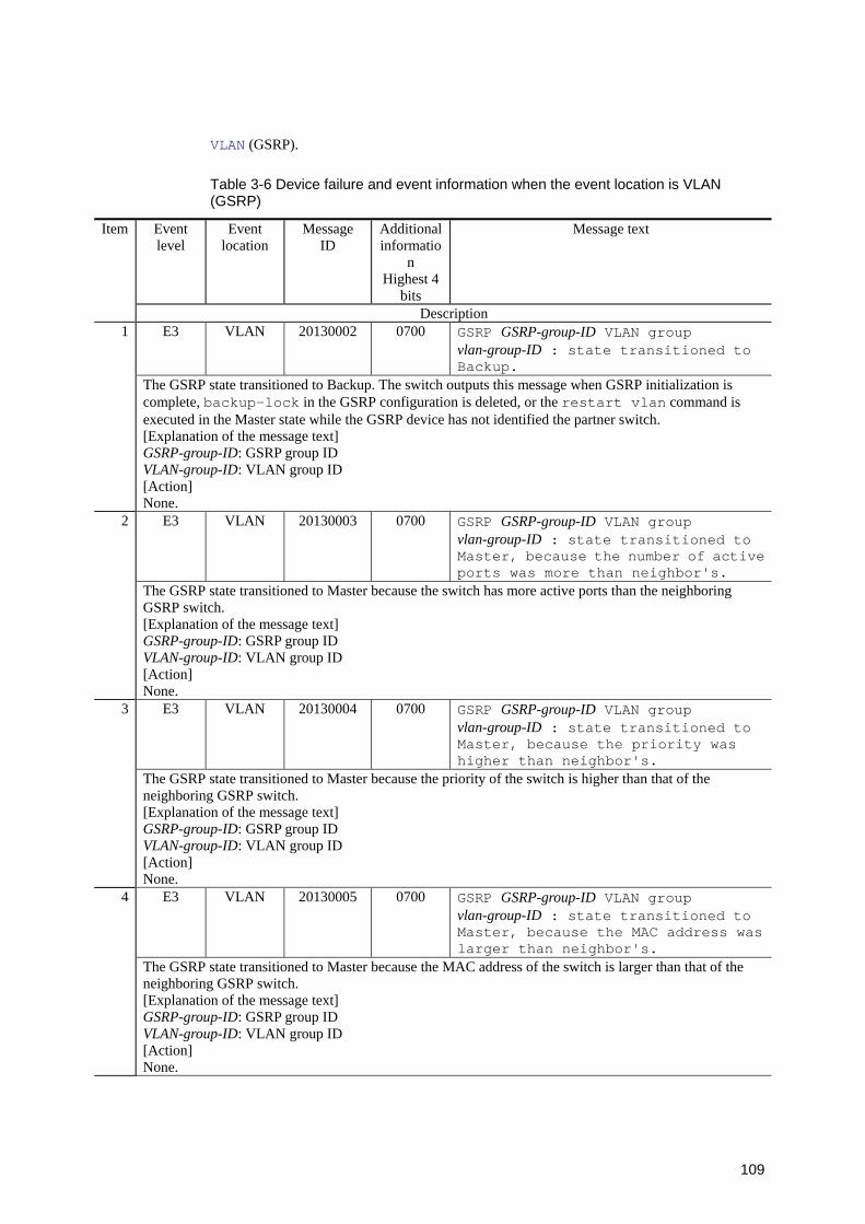
109
VLAN (GSRP).
Table 3-6 Device failure and event information when the event location is VLAN (GSRP)
Event level
Event location
Message ID
Additional informatio
n Highest 4
bits
Message text Item
Description E3 VLAN 20130002 0700 GSRP GSRP-group-ID VLAN group
vlan-group-ID : state transitioned to Backup.
1
The GSRP state transitioned to Backup. The switch outputs this message when GSRP initialization is complete, backup-lock in the GSRP configuration is deleted, or the restart vlan command is executed in the Master state while the GSRP device has not identified the partner switch. [Explanation of the message text] GSRP-group-ID: GSRP group ID VLAN-group-ID: VLAN group ID [Action] None.
E3 VLAN 20130003 0700 GSRP GSRP-group-ID VLAN group vlan-group-ID : state transitioned to Master, because the number of active ports was more than neighbor's.
2
The GSRP state transitioned to Master because the switch has more active ports than the neighboring GSRP switch. [Explanation of the message text] GSRP-group-ID: GSRP group ID VLAN-group-ID: VLAN group ID [Action] None.
E3 VLAN 20130004 0700 GSRP GSRP-group-ID VLAN group vlan-group-ID : state transitioned to Master, because the priority was higher than neighbor's.
3
The GSRP state transitioned to Master because the priority of the switch is higher than that of the neighboring GSRP switch. [Explanation of the message text] GSRP-group-ID: GSRP group ID VLAN-group-ID: VLAN group ID [Action] None.
E3 VLAN 20130005 0700 GSRP GSRP-group-ID VLAN group vlan-group-ID : state transitioned to Master, because the MAC address was larger than neighbor's.
4
The GSRP state transitioned to Master because the MAC address of the switch is larger than that of the neighboring GSRP switch. [Explanation of the message text] GSRP-group-ID: GSRP group ID VLAN-group-ID: VLAN group ID [Action] None.
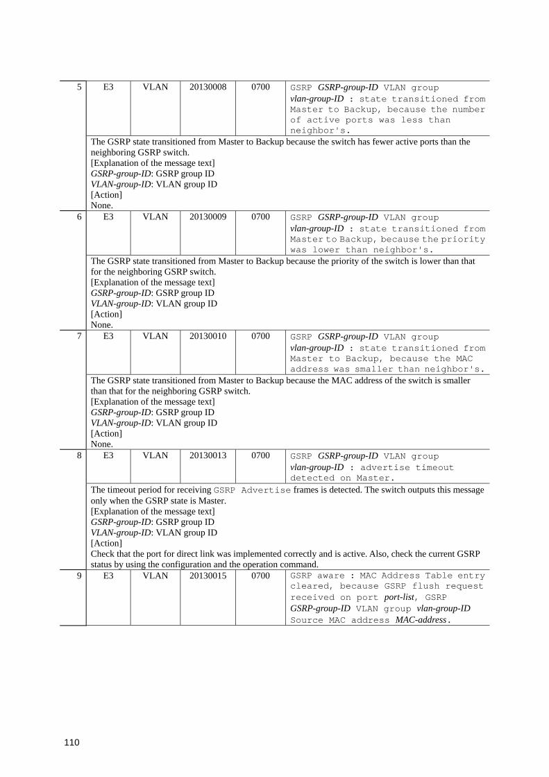
110
E3 VLAN 20130008 0700 GSRP GSRP-group-ID VLAN group vlan-group-ID : state transitioned from Master to Backup, because the number of active ports was less than neighbor's.
5
The GSRP state transitioned from Master to Backup because the switch has fewer active ports than the neighboring GSRP switch. [Explanation of the message text] GSRP-group-ID: GSRP group ID VLAN-group-ID: VLAN group ID [Action] None.
E3 VLAN 20130009 0700 GSRP GSRP-group-ID VLAN group vlan-group-ID : state transitioned from Master to Backup, because the priority was lower than neighbor's.
6
The GSRP state transitioned from Master to Backup because the priority of the switch is lower than that for the neighboring GSRP switch. [Explanation of the message text] GSRP-group-ID: GSRP group ID VLAN-group-ID: VLAN group ID [Action] None.
E3 VLAN 20130010 0700 GSRP GSRP-group-ID VLAN group vlan-group-ID : state transitioned from Master to Backup, because the MAC address was smaller than neighbor's.
7
The GSRP state transitioned from Master to Backup because the MAC address of the switch is smaller than that for the neighboring GSRP switch. [Explanation of the message text] GSRP-group-ID: GSRP group ID VLAN-group-ID: VLAN group ID [Action] None.
E3 VLAN 20130013 0700 GSRP GSRP-group-ID VLAN group vlan-group-ID : advertise timeout detected on Master.
8
The timeout period for receiving GSRP Advertise frames is detected. The switch outputs this message only when the GSRP state is Master. [Explanation of the message text] GSRP-group-ID: GSRP group ID VLAN-group-ID: VLAN group ID [Action] Check that the port for direct link was implemented correctly and is active. Also, check the current GSRP status by using the configuration and the operation command.
9 E3 VLAN 20130015 0700 GSRP aware : MAC Address Table entry cleared, because GSRP flush request received on port port-list, GSRP GSRP-group-ID VLAN group vlan-group-ID Source MAC address MAC-address.
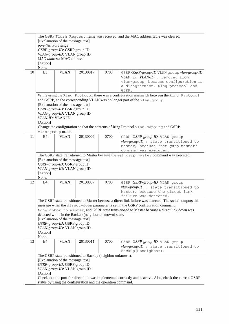
111
The GSRP Flush Request frame was received, and the MAC address table was cleared. [Explanation of the message text] port-list: Port range GSRP-group-ID: GSRP group ID VLAN-group-ID: VLAN group ID MAC-address: MAC address [Action] None.
E3 VLAN 20130017 0700 GSRP GSRP-group-ID VLAN group vlan-group-IDVLAN id VLAN-ID : removed from vlan-group, because configuration is a disagreement, Ring protocol and GSRP.
10
While using the Ring Protocol there was a configuration mismatch between the Ring Protocol and GSRP, so the corresponding VLAN was no longer part of the vlan-group. [Explanation of the message text] GSRP-group-ID: GSRP group ID VLAN-group-ID: VLAN group ID VLAN-ID: VLAN ID [Action] Change the configuration so that the contents of Ring Protocol vlan-mapping and GSRP vlan-group match.
E4 VLAN 20130006 0700 GSRP GSRP-group-ID VLAN group vlan-group-ID : state transitioned to Master, because "set gsrp master" command was executed.
11
The GSRP state transitioned to Master because the set gsrp master command was executed. [Explanation of the message text] GSRP-group-ID: GSRP group ID VLAN-group-ID: VLAN group ID [Action] None.
E4 VLAN 20130007 0700 GSRP GSRP-group-ID VLAN group vlan-group-ID : state transitioned to Master, because the direct link failure was detected.
12
The GSRP state transitioned to Master because a direct link failure was detected. The switch outputs this message when the direct-down parameter is set in the GSRP configuration command Noneighbor-to-master, and GSRP state transitioned to Master because a direct link down was detected while in the Backup (neighbor unknown) state. [Explanation of the message text] GSRP-group-ID: GSRP group ID VLAN-group-ID: VLAN group ID [Action] None.
E4 VLAN 20130011 0700 GSRP GSRP-group-ID VLAN group vlan-group-ID : state transitioned to Backup(Noneighbor).
13
The GSRP state transitioned to Backup (neighbor unknown). [Explanation of the message text] GSRP-group-ID: GSRP group ID VLAN-group-ID: VLAN group ID [Action] Check that the port for direct link was implemented correctly and is active. Also, check the current GSRP status by using the configuration and the operation command.
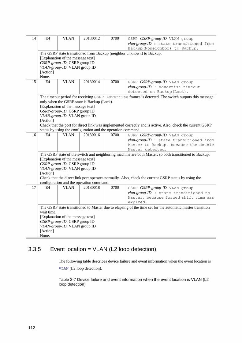
112
E4 VLAN 20130012 0700 GSRP GSRP-group-ID VLAN group vlan-group-ID : state transitioned from Backup(Noneighbor) to Backup.
14
The GSRP state transitioned from Backup (neighbor unknown) to Backup. [Explanation of the message text] GSRP-group-ID: GSRP group ID VLAN-group-ID: VLAN group ID [Action] None.
E4 VLAN 20130014 0700 GSRP GSRP-group-ID VLAN group vlan-group-ID : advertise timeout detected on Backup(Lock).
15
The timeout period for receiving GSRP Advertise frames is detected. The switch outputs this message only when the GSRP state is Backup (Lock). [Explanation of the message text] GSRP-group-ID: GSRP group ID VLAN-group-ID: VLAN group ID [Action] Check that the port for direct link was implemented correctly and is active. Also, check the current GSRP status by using the configuration and the operation command.
E4 VLAN 20130016 0700 GSRP GSRP-group-ID VLAN group vlan-group-ID : state transitioned from Master to Backup, because the double Master detected.
16
The GSRP state of the switch and neighboring machine are both Master, so both transitioned to Backup. [Explanation of the message text] GSRP-group-ID: GSRP group ID VLAN-group-ID: VLAN group ID [Action] Check that the direct link port operates normally. Also, check the current GSRP status by using the configuration and the operation command.
E4 VLAN 20130018 0700 GSRP GSRP-group-ID VLAN group vlan-group-ID : state transitioned to Master, because forced shift time was expired.
17
The GSRP state transitioned to Master due to elapsing of the time set for the automatic master transition wait time. [Explanation of the message text] GSRP-group-ID: GSRP group ID VLAN-group-ID: VLAN group ID [Action] None.
3.3.5 Event location = VLAN (L2 loop detection)
The following table describes device failure and event information when the event location is
VLAN (L2 loop detection).
Table 3-7 Device failure and event information when the event location is VLAN (L2 loop detection)
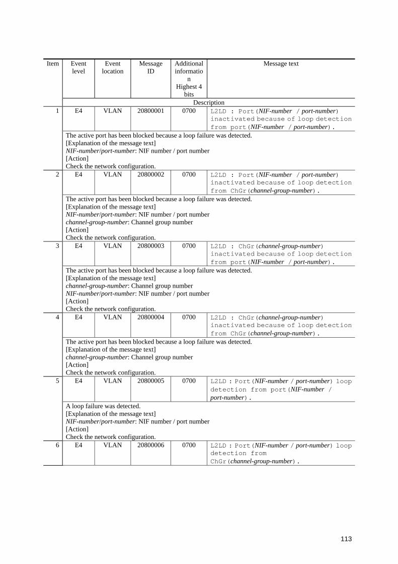
113
Event level
Event location
Message ID
Additional informatio
n Highest 4
bits
Message text Item
Description E4 VLAN 20800001 0700 L2LD : Port(NIF-number / port-number)
inactivated because of loop detection from port(NIF-number / port-number).
1
The active port has been blocked because a loop failure was detected. [Explanation of the message text] NIF-number/port-number: NIF number / port number [Action] Check the network configuration.
E4 VLAN 20800002 0700 L2LD : Port(NIF-number / port-number) inactivated because of loop detection from ChGr(channel-group-number).
2
The active port has been blocked because a loop failure was detected. [Explanation of the message text] NIF-number/port-number: NIF number / port number channel-group-number: Channel group number [Action] Check the network configuration.
E4 VLAN 20800003 0700 L2LD : ChGr(channel-group-number) inactivated because of loop detection from port(NIF-number / port-number).
3
The active port has been blocked because a loop failure was detected. [Explanation of the message text] channel-group-number: Channel group number NIF-number/port-number: NIF number / port number [Action] Check the network configuration.
E4 VLAN 20800004 0700 L2LD : ChGr(channel-group-number) inactivated because of loop detection from ChGr(channel-group-number).
4
The active port has been blocked because a loop failure was detected. [Explanation of the message text] channel-group-number: Channel group number [Action] Check the network configuration.
E4 VLAN 20800005 0700 L2LD : Port(NIF-number / port-number) loop detection from port(NIF-number / port-number).
5
A loop failure was detected. [Explanation of the message text] NIF-number/port-number: NIF number / port number [Action] Check the network configuration.
6 E4 VLAN 20800006 0700 L2LD : Port(NIF-number / port-number) loop detection from ChGr(channel-group-number).
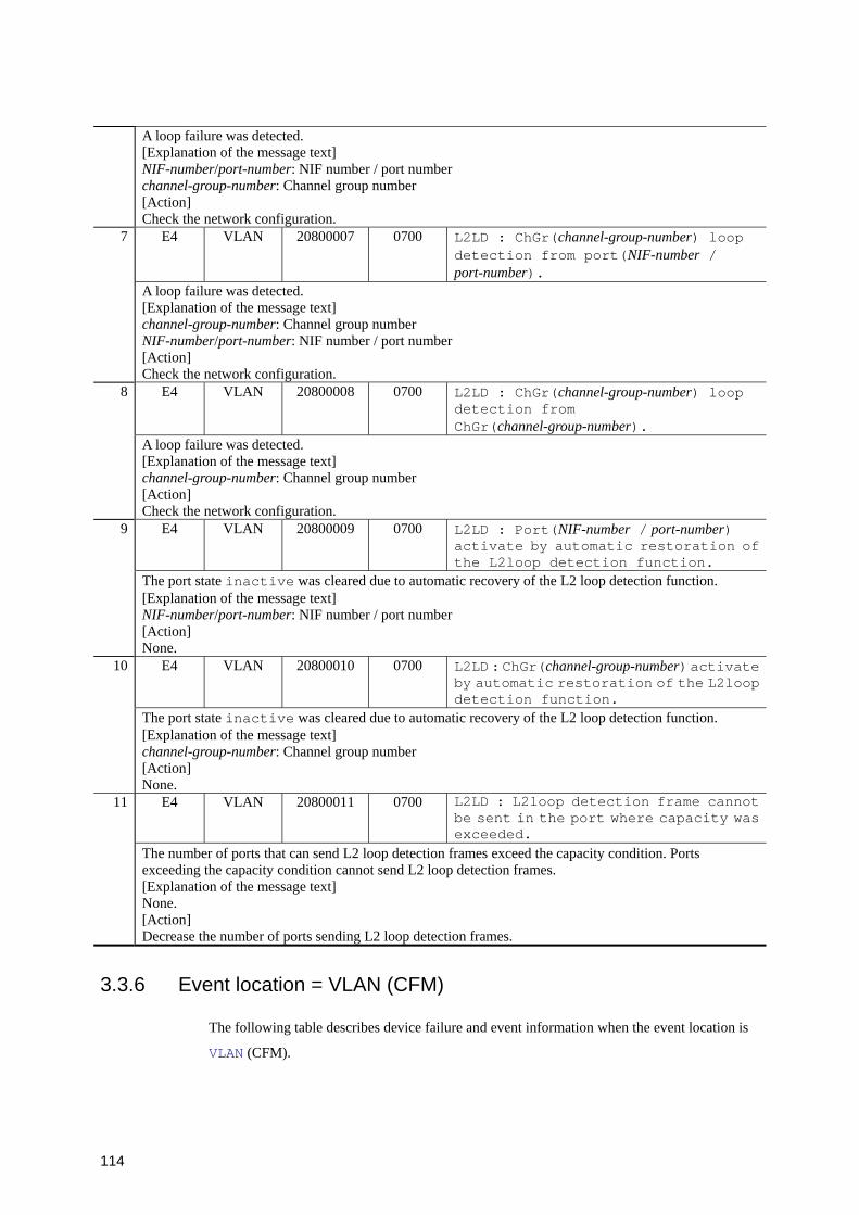
114
A loop failure was detected. [Explanation of the message text] NIF-number/port-number: NIF number / port number channel-group-number: Channel group number [Action] Check the network configuration.
E4 VLAN 20800007 0700 L2LD : ChGr(channel-group-number) loop detection from port(NIF-number / port-number).
7
A loop failure was detected. [Explanation of the message text] channel-group-number: Channel group number NIF-number/port-number: NIF number / port number [Action] Check the network configuration.
E4 VLAN 20800008 0700 L2LD : ChGr(channel-group-number) loop detection from ChGr(channel-group-number).
8
A loop failure was detected. [Explanation of the message text] channel-group-number: Channel group number [Action] Check the network configuration.
E4 VLAN 20800009 0700 L2LD : Port(NIF-number / port-number) activate by automatic restoration of the L2loop detection function.
9
The port state inactive was cleared due to automatic recovery of the L2 loop detection function. [Explanation of the message text] NIF-number/port-number: NIF number / port number [Action] None.
E4 VLAN 20800010 0700 L2LD : ChGr(channel-group-number) activate by automatic restoration of the L2loop detection function.
10
The port state inactive was cleared due to automatic recovery of the L2 loop detection function. [Explanation of the message text] channel-group-number: Channel group number [Action] None.
E4 VLAN 20800011 0700 L2LD : L2loop detection frame cannot be sent in the port where capacity was exceeded.
11
The number of ports that can send L2 loop detection frames exceed the capacity condition. Ports exceeding the capacity condition cannot send L2 loop detection frames. [Explanation of the message text] None. [Action] Decrease the number of ports sending L2 loop detection frames.
3.3.6 Event location = VLAN (CFM)
The following table describes device failure and event information when the event location is
VLAN (CFM).
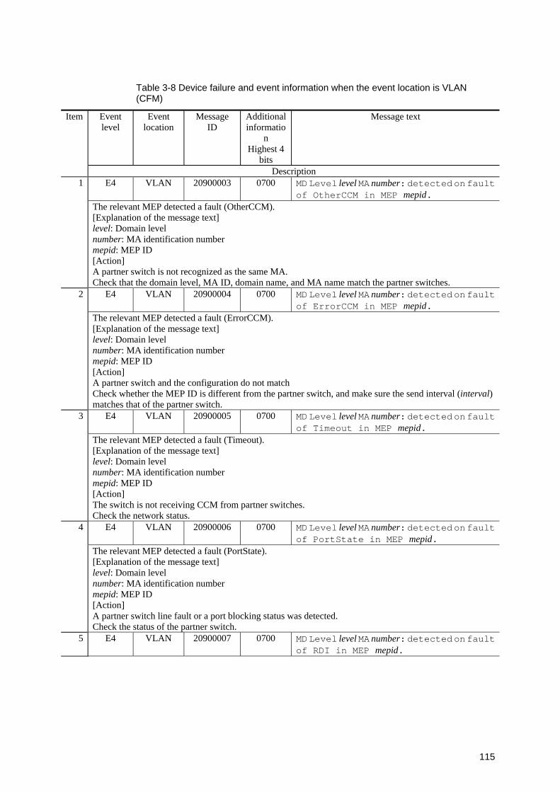
115
Table 3-8 Device failure and event information when the event location is VLAN (CFM)
Event level
Event location
Message ID
Additional informatio
n Highest 4
bits
Message text Item
Description E4 VLAN 20900003 0700 MD Level level MA number: detected on fault
of OtherCCM in MEP mepid. 1
The relevant MEP detected a fault (OtherCCM). [Explanation of the message text] level: Domain level number: MA identification number mepid: MEP ID [Action] A partner switch is not recognized as the same MA. Check that the domain level, MA ID, domain name, and MA name match the partner switches.
E4 VLAN 20900004 0700 MD Level level MA number: detected on fault of ErrorCCM in MEP mepid.
2
The relevant MEP detected a fault (ErrorCCM). [Explanation of the message text] level: Domain level number: MA identification number mepid: MEP ID [Action] A partner switch and the configuration do not match Check whether the MEP ID is different from the partner switch, and make sure the send interval (interval) matches that of the partner switch.
E4 VLAN 20900005 0700 MD Level level MA number: detected on fault of Timeout in MEP mepid.
3
The relevant MEP detected a fault (Timeout). [Explanation of the message text] level: Domain level number: MA identification number mepid: MEP ID [Action] The switch is not receiving CCM from partner switches. Check the network status.
E4 VLAN 20900006 0700 MD Level level MA number: detected on fault of PortState in MEP mepid.
4
The relevant MEP detected a fault (PortState). [Explanation of the message text] level: Domain level number: MA identification number mepid: MEP ID [Action] A partner switch line fault or a port blocking status was detected. Check the status of the partner switch.
5 E4 VLAN 20900007 0700 MD Level level MA number: detected on fault of RDI in MEP mepid.
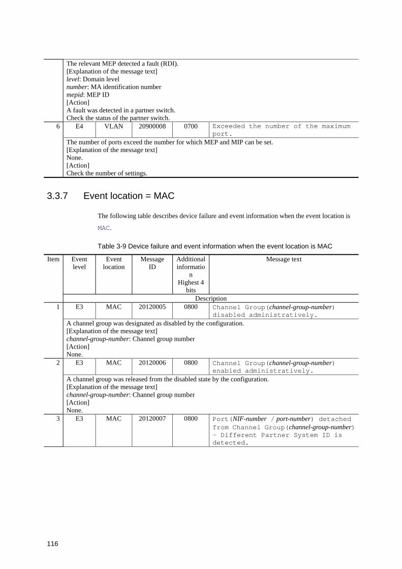
116
The relevant MEP detected a fault (RDI). [Explanation of the message text] level: Domain level number: MA identification number mepid: MEP ID [Action] A fault was detected in a partner switch. Check the status of the partner switch.
E4 VLAN 20900008 0700 Exceeded the number of the maximum port.
6
The number of ports exceed the number for which MEP and MIP can be set. [Explanation of the message text] None. [Action] Check the number of settings.
3.3.7 Event location = MAC
The following table describes device failure and event information when the event location is
MAC.
Table 3-9 Device failure and event information when the event location is MAC
Event level
Event location
Message ID
Additional informatio
n Highest 4
bits
Message text Item
Description E3 MAC 20120005 0800 Channel Group(channel-group-number)
disabled administratively. 1
A channel group was designated as disabled by the configuration. [Explanation of the message text] channel-group-number: Channel group number [Action] None.
E3 MAC 20120006 0800 Channel Group(channel-group-number) enabled administratively.
2
A channel group was released from the disabled state by the configuration. [Explanation of the message text] channel-group-number: Channel group number [Action] None.
3 E3 MAC 20120007 0800 Port(NIF-number / port-number) detached from Channel Group(channel-group-number) - Different Partner System ID is detected.

117
The system ID of a partner switch does not match between the ports for LACP mode link aggregation, and the port was detached from the channel group. [Explanation of the message text] NIF-number/port-number: NIF number / port number channel-group-number: Channel group number [Action] Check the following: 1. Is the connection with the partner switch correct? 2. Is the system ID setting of the partner switch correct?
E3 MAC 20120008 0800 Port(NIF-number / port-number) detached from Channel Group(channel-group-number) - Different Partner Key is detected.
4
The key of a partner switch does not match between the ports for LACP mode link aggregation, and the port was detached from the channel group. [Explanation of the message text] NIF-number/port-number: NIF number / port number channel-group-number: Channel group number [Action] Check the following: 1. Is the connection with the partner switch correct? 2. Is the key setting of the partner switch correct?
E3 MAC 20120009 0800 Port(NIF-number / port-number) removed from Channel Group(channel-group-number).
5
A port was detached from the channel group because of a configuration link deletion. [Explanation of the message text] NIF-number/port-number: NIF number / port number channel-group-number: Channel group number [Action] None.
E3 MAC 20120010 0800 Port(NIF-number / port-number) detached from Channel Group(channel-group-number) - Port down.
6
A line is down, and the port was detached from the channel group. [Explanation of the message text] NIF-number/port-number: NIF number / port number channel-group-number: Channel group number [Action] Check the line status.
E3 MAC 20120011 0800 Port(NIF-number / port-number) detached from Channel Group(channel-group-number) - Different Port data rate .
7
Lines that have different data rates (speeds) exist in the channel group. Lines that have low data rates were detached from the channel group. [Explanation of the message text] NIF-number/port-number: NIF number / port number channel-group-number: Channel group number [Action] For detached lines, check the settings of this switch and partner switches.
E3 MAC 20120012 0800 Port(NIF-number / port-number) detached from Channel Group(channel-group-number) - Half-duplex port.
8
Lines operating in half-duplex mode were detached from the channel group. [Explanation of the message text] NIF-number/port-number: NIF number / port number channel-group-number: Channel group number [Action] For detached lines, check the settings of this switch and partner switches.
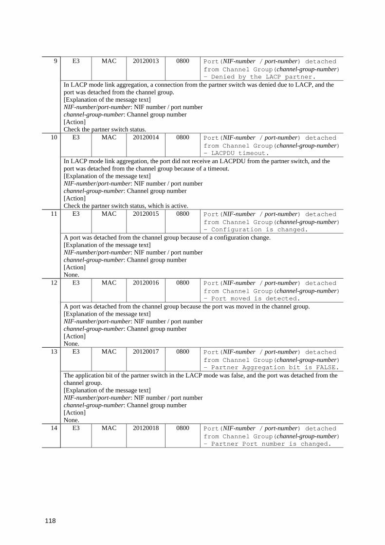
118
E3 MAC 20120013 0800 Port(NIF-number / port-number) detached from Channel Group(channel-group-number) - Denied by the LACP partner.
9
In LACP mode link aggregation, a connection from the partner switch was denied due to LACP, and the port was detached from the channel group. [Explanation of the message text] NIF-number/port-number: NIF number / port number channel-group-number: Channel group number [Action] Check the partner switch status.
E3 MAC 20120014 0800 Port(NIF-number / port-number) detached from Channel Group(channel-group-number) - LACPDU timeout.
10
In LACP mode link aggregation, the port did not receive an LACPDU from the partner switch, and the port was detached from the channel group because of a timeout. [Explanation of the message text] NIF-number/port-number: NIF number / port number channel-group-number: Channel group number [Action] Check the partner switch status, which is active.
E3 MAC 20120015 0800 Port(NIF-number / port-number) detached from Channel Group(channel-group-number) - Configuration is changed.
11
A port was detached from the channel group because of a configuration change. [Explanation of the message text] NIF-number/port-number: NIF number / port number channel-group-number: Channel group number [Action] None.
E3 MAC 20120016 0800 Port(NIF-number / port-number) detached from Channel Group(channel-group-number) - Port moved is detected.
12
A port was detached from the channel group because the port was moved in the channel group. [Explanation of the message text] NIF-number/port-number: NIF number / port number channel-group-number: Channel group number [Action] None.
E3 MAC 20120017 0800 Port(NIF-number / port-number) detached from Channel Group(channel-group-number) - Partner Aggregation bit is FALSE.
13
The application bit of the partner switch in the LACP mode was false, and the port was detached from the channel group. [Explanation of the message text] NIF-number/port-number: NIF number / port number channel-group-number: Channel group number [Action] None.
14 E3 MAC 20120018 0800 Port(NIF-number / port-number) detached from Channel Group(channel-group-number) - Partner Port number is changed.
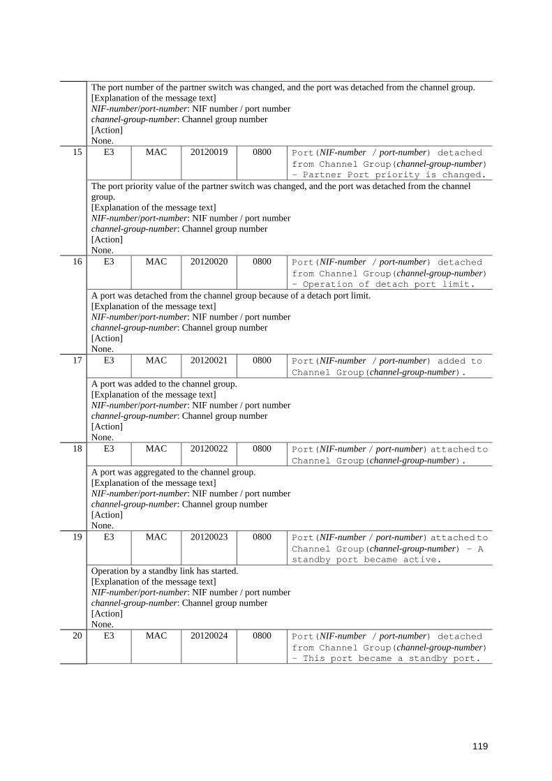
119
The port number of the partner switch was changed, and the port was detached from the channel group. [Explanation of the message text] NIF-number/port-number: NIF number / port number channel-group-number: Channel group number [Action] None.
E3 MAC 20120019 0800 Port(NIF-number / port-number) detached from Channel Group(channel-group-number) - Partner Port priority is changed.
15
The port priority value of the partner switch was changed, and the port was detached from the channel group. [Explanation of the message text] NIF-number/port-number: NIF number / port number channel-group-number: Channel group number [Action] None.
E3 MAC 20120020 0800 Port(NIF-number / port-number) detached from Channel Group(channel-group-number) - Operation of detach port limit.
16
A port was detached from the channel group because of a detach port limit. [Explanation of the message text] NIF-number/port-number: NIF number / port number channel-group-number: Channel group number [Action] None.
E3 MAC 20120021 0800 Port(NIF-number / port-number) added to Channel Group(channel-group-number).
17
A port was added to the channel group. [Explanation of the message text] NIF-number/port-number: NIF number / port number channel-group-number: Channel group number [Action] None.
E3 MAC 20120022 0800 Port(NIF-number / port-number) attached to Channel Group(channel-group-number).
18
A port was aggregated to the channel group. [Explanation of the message text] NIF-number/port-number: NIF number / port number channel-group-number: Channel group number [Action] None.
E3 MAC 20120023 0800 Port(NIF-number / port-number) attached to Channel Group(channel-group-number) - A standby port became active.
19
Operation by a standby link has started. [Explanation of the message text] NIF-number/port-number: NIF number / port number channel-group-number: Channel group number [Action] None.
20 E3 MAC 20120024 0800 Port(NIF-number / port-number) detached from Channel Group(channel-group-number) - This port became a standby port.

120
Operation by a standby link has started. [Explanation of the message text] NIF-number/port-number: NIF number / port number channel-group-number: Channel group number [Action] None.
E4 MAC 20120002 0800 Channel Group(channel-group-number) is Up.21 The channel group status is Up. [Explanation of the message text] channel-group-number: Channel group number [Action] None.
E4 MAC 20120003 0800 Channel Group(channel-group-number) is Down - All port detached.
22
All ports in the channel group are detached, and the channel group status is Down. [Explanation of the message text] channel-group-number: Channel group number [Action] For line connection status with partner switches: 1. Check whether the line is down. 2. Check whether the line is half-duplex. 3. Check that the LACP settings of the partner switch and line statuses are normal.
E4 MAC 20120004 0800 Channel Group(channel-group-number) is Down - The number of the detached port exceeded the configured number.
23
The number of detached ports in the channel group exceed the set limit, and the channel group status is Down. [Explanation of the message text] channel-group-number: Channel group number [Action] For line connection status with partner switches: 1. Check whether the line is down. 2. Check whether the line is half-duplex. 3. Check that the partner switch LACP setting and line statuses are normal.
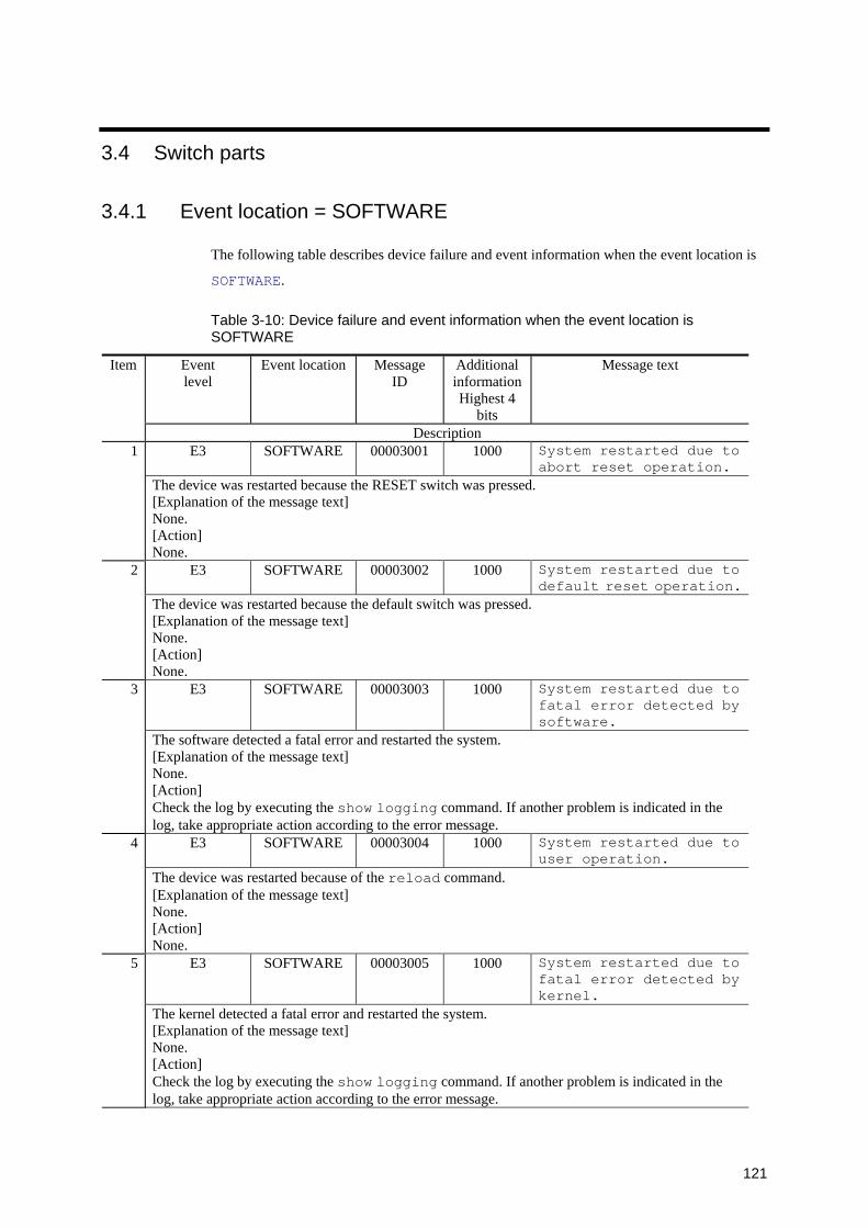
121
3.4 Switch parts
3.4.1 Event location = SOFTWARE
The following table describes device failure and event information when the event location is
SOFTWARE.
Table 3-10: Device failure and event information when the event location is SOFTWARE
Event level
Event location Message ID
Additional informationHighest 4
bits
Message text Item
Description E3 SOFTWARE 00003001 1000 System restarted due to
abort reset operation. 1
The device was restarted because the RESET switch was pressed. [Explanation of the message text] None. [Action] None.
E3 SOFTWARE 00003002 1000 System restarted due to default reset operation.
2
The device was restarted because the default switch was pressed. [Explanation of the message text] None. [Action] None.
E3 SOFTWARE 00003003 1000 System restarted due to fatal error detected by software.
3
The software detected a fatal error and restarted the system. [Explanation of the message text] None. [Action] Check the log by executing the show logging command. If another problem is indicated in the log, take appropriate action according to the error message.
E3 SOFTWARE 00003004 1000 System restarted due to user operation.
4
The device was restarted because of the reload command. [Explanation of the message text] None. [Action] None.
E3 SOFTWARE 00003005 1000 System restarted due to fatal error detected by kernel.
5
The kernel detected a fatal error and restarted the system. [Explanation of the message text] None. [Action] Check the log by executing the show logging command. If another problem is indicated in the log, take appropriate action according to the error message.
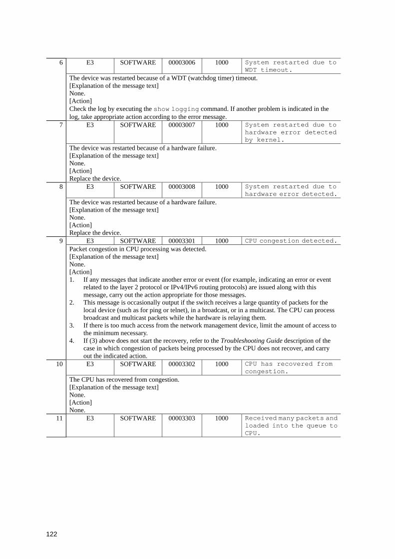
122
E3 SOFTWARE 00003006 1000 System restarted due to WDT timeout.
6
The device was restarted because of a WDT (watchdog timer) timeout. [Explanation of the message text] None. [Action] Check the log by executing the show logging command. If another problem is indicated in the log, take appropriate action according to the error message.
E3 SOFTWARE 00003007 1000 System restarted due to hardware error detected by kernel.
7
The device was restarted because of a hardware failure. [Explanation of the message text] None. [Action] Replace the device.
E3 SOFTWARE 00003008 1000 System restarted due to hardware error detected.
8
The device was restarted because of a hardware failure. [Explanation of the message text] None. [Action] Replace the device.
E3 SOFTWARE 00003301 1000 CPU congestion detected.9 Packet congestion in CPU processing was detected. [Explanation of the message text] None. [Action] 1. If any messages that indicate another error or event (for example, indicating an error or event
related to the layer 2 protocol or IPv4/IPv6 routing protocols) are issued along with this message, carry out the action appropriate for those messages.
2. This message is occasionally output if the switch receives a large quantity of packets for the local device (such as for ping or telnet), in a broadcast, or in a multicast. The CPU can process broadcast and multicast packets while the hardware is relaying them.
3. If there is too much access from the network management device, limit the amount of access to the minimum necessary.
4. If (3) above does not start the recovery, refer to the Troubleshooting Guide description of the case in which congestion of packets being processed by the CPU does not recover, and carry out the indicated action. E3 SOFTWARE 00003302 1000 CPU has recovered from
congestion. 10
The CPU has recovered from congestion. [Explanation of the message text] None. [Action] None.
11 E3 SOFTWARE 00003303 1000 Received many packets and loaded into the queue to CPU.
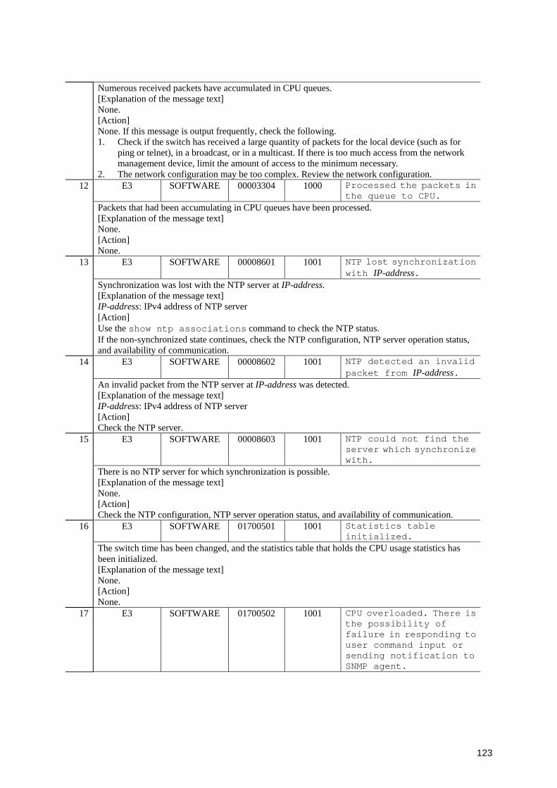
123
Numerous received packets have accumulated in CPU queues. [Explanation of the message text] None. [Action] None. If this message is output frequently, check the following. 1. Check if the switch has received a large quantity of packets for the local device (such as for
ping or telnet), in a broadcast, or in a multicast. If there is too much access from the network management device, limit the amount of access to the minimum necessary.
2. The network configuration may be too complex. Review the network configuration. E3 SOFTWARE 00003304 1000 Processed the packets in
the queue to CPU. 12
Packets that had been accumulating in CPU queues have been processed. [Explanation of the message text] None. [Action] None.
E3 SOFTWARE 00008601 1001 NTP lost synchronization with IP-address.
13
Synchronization was lost with the NTP server at IP-address. [Explanation of the message text] IP-address: IPv4 address of NTP server [Action] Use the show ntp associations command to check the NTP status. If the non-synchronized state continues, check the NTP configuration, NTP server operation status, and availability of communication.
E3 SOFTWARE 00008602 1001 NTP detected an invalid packet from IP-address.
14
An invalid packet from the NTP server at IP-address was detected. [Explanation of the message text] IP-address: IPv4 address of NTP server [Action] Check the NTP server.
E3 SOFTWARE 00008603 1001 NTP could not find the server which synchronize with.
15
There is no NTP server for which synchronization is possible. [Explanation of the message text] None. [Action] Check the NTP configuration, NTP server operation status, and availability of communication.
E3 SOFTWARE 01700501 1001 Statistics table initialized.
16
The switch time has been changed, and the statistics table that holds the CPU usage statistics has been initialized. [Explanation of the message text] None. [Action] None.
17 E3 SOFTWARE 01700502 1001 CPU overloaded. There is the possibility of failure in responding to user command input or sending notification to SNMP agent.
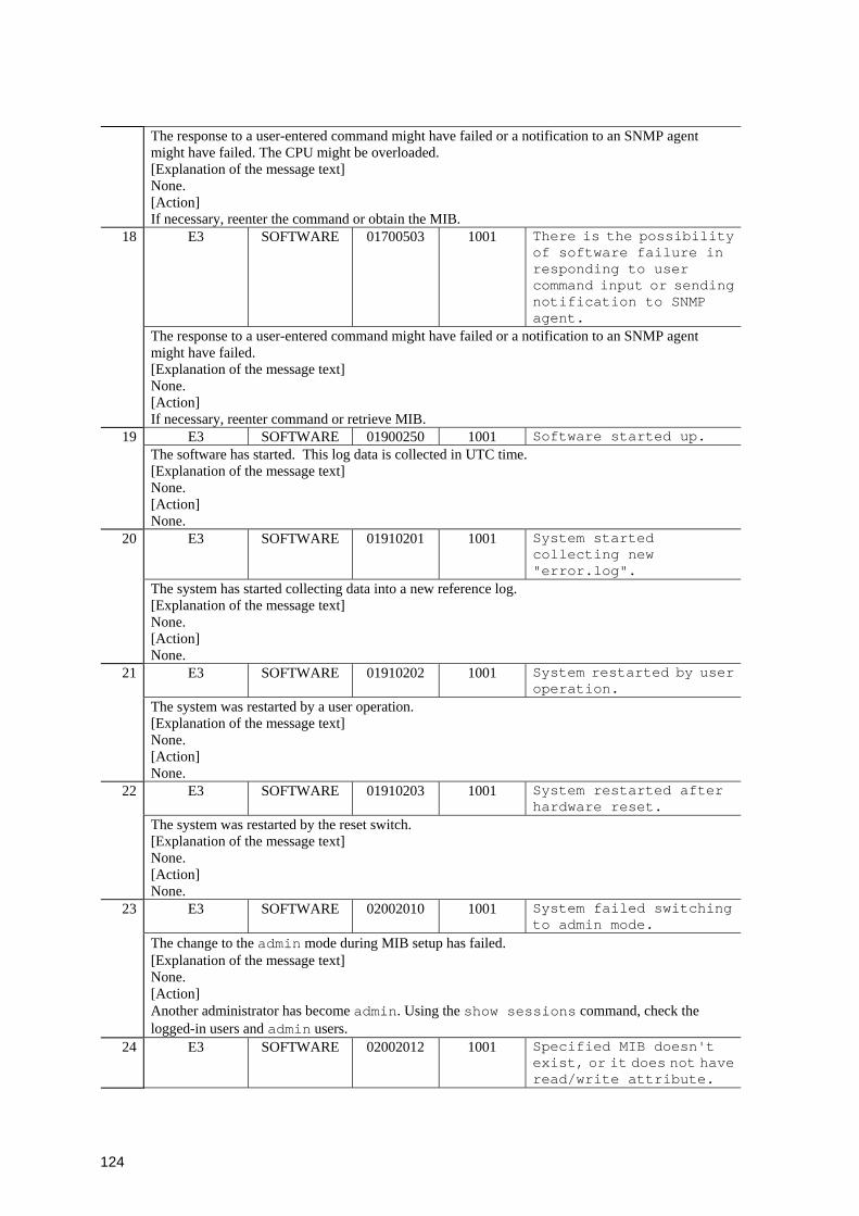
124
The response to a user-entered command might have failed or a notification to an SNMP agent might have failed. The CPU might be overloaded. [Explanation of the message text] None. [Action] If necessary, reenter the command or obtain the MIB.
E3 SOFTWARE 01700503 1001 There is the possibility of software failure in responding to user command input or sending notification to SNMP agent.
18
The response to a user-entered command might have failed or a notification to an SNMP agent might have failed. [Explanation of the message text] None. [Action] If necessary, reenter command or retrieve MIB.
E3 SOFTWARE 01900250 1001 Software started up. 19 The software has started. This log data is collected in UTC time. [Explanation of the message text] None. [Action] None.
E3 SOFTWARE 01910201 1001 System started collecting new "error.log".
20
The system has started collecting data into a new reference log. [Explanation of the message text] None. [Action] None.
E3 SOFTWARE 01910202 1001 System restarted by user operation.
21
The system was restarted by a user operation. [Explanation of the message text] None. [Action] None.
E3 SOFTWARE 01910203 1001 System restarted after hardware reset.
22
The system was restarted by the reset switch. [Explanation of the message text] None. [Action] None.
E3 SOFTWARE 02002010 1001 System failed switching to admin mode.
23
The change to the admin mode during MIB setup has failed. [Explanation of the message text] None. [Action] Another administrator has become admin. Using the show sessions command, check the logged-in users and admin users.
24 E3 SOFTWARE 02002012 1001 Specified MIB doesn't exist, or it does not have read/write attribute.
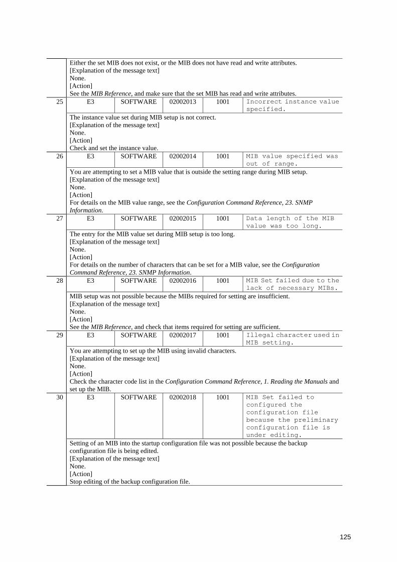
125
Either the set MIB does not exist, or the MIB does not have read and write attributes. [Explanation of the message text] None. [Action] See the MIB Reference, and make sure that the set MIB has read and write attributes.
E3 SOFTWARE 02002013 1001 Incorrect instance value specified.
25
The instance value set during MIB setup is not correct. [Explanation of the message text] None. [Action] Check and set the instance value.
E3 SOFTWARE 02002014 1001 MIB value specified was out of range.
26
You are attempting to set a MIB value that is outside the setting range during MIB setup. [Explanation of the message text] None. [Action] For details on the MIB value range, see the Configuration Command Reference, 23. SNMP Information.
E3 SOFTWARE 02002015 1001 Data length of the MIB value was too long.
27
The entry for the MIB value set during MIB setup is too long. [Explanation of the message text] None. [Action] For details on the number of characters that can be set for a MIB value, see the Configuration Command Reference, 23. SNMP Information.
E3 SOFTWARE 02002016 1001 MIB Set failed due to the lack of necessary MIBs.
28
MIB setup was not possible because the MIBs required for setting are insufficient. [Explanation of the message text] None. [Action] See the MIB Reference, and check that items required for setting are sufficient.
E3 SOFTWARE 02002017 1001 Illegal character used in MIB setting.
29
You are attempting to set up the MIB using invalid characters. [Explanation of the message text] None. [Action] Check the character code list in the Configuration Command Reference, 1. Reading the Manuals and set up the MIB.
E3 SOFTWARE 02002018 1001 MIB Set failed to configured the configuration file because the preliminary configuration file is under editing.
30
Setting of an MIB into the startup configuration file was not possible because the backup configuration file is being edited. [Explanation of the message text] None. [Action] Stop editing of the backup configuration file.

126
E3 SOFTWARE 02002019 1001 Failed in contact the configuration file while setting up MIB.
31
Access to the startup configuration file for MIB settings failed. [Explanation of the message text] None. [Action] Eliminate the cause of the access failure, and try again.
E3 SOFTWARE 02002020 1001 MIB value has failed to establish. Errors occurred in the "config" command.
32
An error occurred while editing the configuration at MIB setup, and the MIB could not be set. [Explanation of the message text] None. [Action] For details on configuration errors, see Configuration editing error messages in the manual Configuration Command Reference.
E3 SOFTWARE 02002021 1001 Not all MIB configured.33 MIB setup failed, and only some of the MIB values were set. [Explanation of the message text] None. [Action] Try setup again. If the retry still does not work, log in (for example, by using telnet) and set the MIB values.
E3 SOFTWARE 02002023 1001 System failed to save the configuration while processing MIB settings.
34
While setting up MIB from an SNMP manager, an error occurred during processing to save the configuration. [Explanation of the message text] None. [Action] The configuration has not been saved. Save it (for example, by using telnet).
E3 SOFTWARE 02002024 1001 object-name set as mib-value at the request of IP-address.
35
object-name was set to mib-value because of a request from IP-address. [Explanation of the message text] object-name: MIB object mnemonic mib-value: MIB value IP-address: IPv4 or IPv6 address of the SNMP manager [Action] None.
E3 SOFTWARE 02002025 1001 SNMP: MAC address table entry cleared at the request of IP-address
36
The MAC address table was cleared due to a MAC address table clear request from the SNMP manager at IP-address. [Explanation of the message text] IP-address: IPv4 or IPv6 address of the SNMP manager [Action] None.
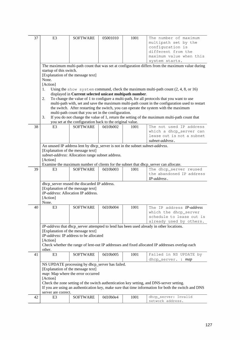
127
E3 SOFTWARE 05001010 1001 The number of maximum multipath set by the configuration is different from the maximum value when this system starts.
37
The maximum multi-path count that was set at configuration differs from the maximum value during startup of this switch. [Explanation of the message text] None. [Action] 1. Using the show system command, check the maximum multi-path count (2, 4, 8, or 16)
displayed in Current selected unicast multipath number. 2. To change the value of 1 to configure a multi-path, for all protocols that you want to use
multi-path with, set and save the maximum multi-path count in the configuration used to restart the switch. After restarting the switch, you can operate the system with the maximum multi-path count that you set in the configuration.
3. If you do not change the value of 1, return the setting of the maximum multi-path count that you set at the configuration back to the original value. E3 SOFTWARE 0d10b002 1001 The not used IP address
which a dhcp_server can lease out is not a subnet subnet-address.
38
An unused IP address lent by dhcp_server is not in the subnet subnet-address. [Explanation of the message text] subnet-address: Allocation range subnet address. [Action] Examine the maximum number of clients for the subnet that dhcp_server can allocate.
E3 SOFTWARE 0d10b003 1001 The dhcp_server reused the abandoned IP address IP-address.
39
dhcp_server reused the discarded IP address. [Explanation of the message text] IP-address: Allocation IP address. [Action] None.
E3 SOFTWARE 0d10b004 1001 The IP address IP-address which the dhcp_server schedule to lease out is already used by others.
40
IP-address that dhcp_server attempted to lend has been used already in other locations. [Explanation of the message text] IP-address: IP address to be allocated [Action] Check whether the range of lent-out IP addresses and fixed allocated IP addresses overlap each other.
E3 SOFTWARE 0d10b005 1001 Failed in NS UPDATE by dhcp_server. : map
41
NS UPDATE processing by dhcp_server has failed. [Explanation of the message text] map: Map where the error occurred [Action] Check the zone setting of the switch authentication key setting, and DNS-server setting. If you are using an authentication key, make sure that time information for both the switch and DNS server are correct.
42 E3 SOFTWARE 0d10b0e4 1001 dhcp_server: Invalid network address.
128
The DHCP server detected an invalid configuration. An invalid network address was specified. [Explanation of the message text] None. [Action] Delete the previously-entered setting, and respecify the setting using a correct network address.
E3 SOFTWARE 0d10b0ec 1001 dhcp_server: Invalid key.(ip dhcp key ... secret-hmac-md5 ...)
43
The DHCP server detected an invalid configuration. There is an invalid key. [Explanation of the message text] None. [Action] Delete the previously-entered setting, and respecify the setting using a correct key.
E3 SOFTWARE 0d10b0ee 1001 dhcp_server: Invalid IP address. (ip dhcp excluded-address ...)
44
The DHCP server detected an invalid configuration. An invalid exclusion address range was specified. [Explanation of the message text] None. [Action] Delete the previously-entered setting, and respecify the setting using a correct exclusion address range.
E3 SOFTWARE 0e008001 1000 Virtual router VRID of interface-name state has transitioned to state.
45
The virtual router active state transitioned to state. [Explanation of the message text] VRID: Virtual router ID interface-name: Name of interface on which VRRP is configured state: Virtual router state [Action] None.
E3 SOFTWARE 0e008002 1000 Virtual router VRID of interface-name received VRRP packet with IP TTL not equal to 255.
46
The virtual router received a VRRP ADVERTISEMENT packet whose TTL (Time-to-Live) in the IP header was not 255. [Explanation of the message text] VRID: Virtual router ID interface-name: Name of interface on which VRRP is configured [Action] Check the remote devices that make up the same virtual router.
E3 SOFTWARE 0e008003 1000 Virtual router VRID of interface-name received VRRP packet that length less than the length of the VRRP header.
47
The virtual router received a VRRP ADVERTISEMENT packet that had an invalid length. [Explanation of the message text] VRID: Virtual router ID interface-name: Name of interface on which VRRP is configured [Action] Check the remote devices that make up the same virtual router.

129
E3 SOFTWARE 0e008004 1000 Virtual router VRID of interface-name received VRRP packet that does not pass the authentication check.
48
Authentication of a received VRRP ADVERTISEMENT packet failed. [Explanation of the message text] VRID: Virtual router ID interface-name: Name of interface on which VRRP is configured [Action] Check the password settings for this switch and the partner switch that make up the same virtual router.
E3 SOFTWARE 0e008005 1000 Virtual router VRID of interface-name received VRRP packet for which the address list does not match the locally configured list for the virtual router.
49
The IP address of a virtual router specified in a received VRRP ADVERTISEMENT packet does not match the settings of the switch. [Explanation of the message text] VRID: Virtual router ID interface-name: Name of interface on which VRRP is configured [Action] Check the IP address settings of virtual routers for the switch and for the partner switch that make up the same virtual router.
E3 SOFTWARE 0e008006 1000 Virtual router VRID of interface-name received VRRP packet for which the advertisement interval is different than the one configured for local virtual router.
50
The transmission interval specified in a received VRRP ADVERTISEMENT packet does not match the settings of the switch. [Explanation of the message text] VRID: Virtual router ID interface-name: Name of interface on which VRRP is configured [Action] Check the transmission intervals for this switch and the partner switch that make up the same virtual router.
E3 SOFTWARE 0e008007 1000 VRRP packet received with unsupported version number.
51
The VRRP version specified in a received VRRP ADVERTISEMENT packet does not match the VRRP version of the switch. [Explanation of the message text] None. [Action] When constructing this switch with a virtual router, set the VRRP version of the partner switch to 2 for IPv4, and 3 for IPv6, respectively.
52 E3 SOFTWARE 0e008008 1000 Virtual router VRID of interface-name priority was changed to priority.
130
The VRRP priority was changed to priority. [Explanation of the message text] VRID: Virtual router ID interface-name: Name of interface on which VRRP is configured priority: Virtual router priority [Action] None.
E3 SOFTWARE 0e008012 1000 Virtual router VRID of interface-name was finished.
53
The virtual router ended. [Explanation of the message text] VRID: Virtual router ID interface-name: Name of interface on which VRRP is configured [Action] None.
E3 SOFTWARE 0e008015 1000 Virtual router VRID of interface-name received VRRP packet with IP HopLimit not equal to 255.
54
The virtual router received a VRRP ADVERTISEMENT packet whose HopLimit in the IP header was not 255. [Explanation of the message text] VRID: Virtual router ID interface-name: Name of interface on which VRRP is configured [Action] Check the remote devices that make up the same virtual router.
E3 SOFTWARE 0e008016 1000 Virtual router VRID of interface-name priority changed to priority, because error detected on line by vrrp-polling.
55
VRRP polling detected a line fault, and the VRRP priority was changed to priority. [Explanation of the message text] VRID: Virtual router ID interface-name: Name of interface on which VRRP is configured priority: Virtual router priority [Action] If switching occurs frequently, adjusting the configuration might solve the problem.
E3 SOFTWARE 0e008017 1000 interface-name assigned virtual router VRID is down because error detected on line by vrrp-polling.
56
The interface in which VRRP is set is down because VRRP polling detected a line fault. [Explanation of the message text] interface-name: Name of interface on which VRRP is configured VRID: Virtual router ID [Action] If switching occurs frequently, adjusting the configuration might solve the problem.
57 E3 SOFTWARE 0e008018 1000 interface-name assigned virtual router VRID is up because recovery detected on line by vrrp-polling.
131
The interface in which VRRP is set was brought up because VRRP polling detected recovery from a fault. [Explanation of the message text] interface-name: Name of interface on which VRRP is configured VRID: Virtual router ID [Action] None.
E3 SOFTWARE 0e008019 1000 Critical interface of interface-name is down.
58
A fault-monitoring interface is down. [Explanation of the message text] interface-name: Interface name of the fault-monitoring target [Action] None.
E3 SOFTWARE 0e008020 1000 Critical interface of interface-name is up.
59
A fault-monitoring interface is up. [Explanation of the message text] interface-name: Interface name of a fault-monitoring target. [Action] None.
E3 SOFTWARE 0e008025 1000 Critical interface of interface-type interface-number is down.
60
A fault-monitoring interface is down. [Explanation of the message text] interface-type: Interface that is specified as the fault-monitoring interface. • gigabitethernet: 10BASE-T/100BASE-TX/1000BASE-T, 100BASE-FX, 1000BASE-X • tengigabitethernet: 10GBASE-R • port-channel: channel-group interface-number: Interface number specified for the failure monitoring interface • NIF-number/port-number: NIF number / port number (For gigabitethernet or tengigabitethernet) • channel-group-number: Channel group number (For port-channel) [Action] None.
E3 SOFTWARE 0e008026 1000 Critical interface of interface-type interface-number is up.
61
A fault-monitoring interface is up. [Explanation of the message text] interface-type: Interface that is specified as the fault-monitoring interface. • gigabitethernet: 10BASE-T/100BASE-TX/1000BASE-T, 100BASE-FX, 1000BASE-X • tengigabitethernet: 10GBASE-R • port-channel: channel-group interface-number: Interface number specified for the failure monitoring interface • NIF-number/port-number: NIF number / port number(For gigabitethernet or tengigabitethernet) • channel-group-number: Channel group number(For port-channel) [Action] None.
62 E3 SOFTWARE 0e008027 1000 Critical interface of interface-number is up. But priority not changed because of different interface type.
132
A fault-monitoring interface is up at mixed speeds. The priority did not change. [Explanation of the message text] interface-number: Interface number specified for the failure monitoring interface • NIF-number/port-number: NIF number / port number [Action] None.
E3 SOFTWARE 0f306003 0f406003
1001 The multicast routing program will restart, because the multicast (PIM) max-interfaces configuration changed.
63
IP multicast routing program will restart because the IP multicast (PIM) information of the running configuration was changed by the configuration command ip pim max-interface. [Explanation of the message text] None. [Action] None.
E3 SOFTWARE 0f406004 1001 IPv4 multicast routing entry had exceeded maximum value number for limit, entry has discarded.
64
An entry was discarded because the items of IPv4 multicast routing information exceed the limit maximum value of number. [Explanation of the message text] number: Maximum number of items of IPv4 multicast routing information [Action] Unauthorized access might have been occurred. • Check if there were more than the expected number of additional requests for multicast routing
information. The number of items of multicast routing information exceed the maximum value because of the limit.
• Check the configuration (ip pim mroute-limit command). • Check the network configuration and reconsider the configuration of this device.
E3 SOFTWARE 0f406005 1001 IPv4 multicast routing entry has recovered from the state of discard.
65
IPv4 multicast routing information has recovered from the state in which entries were discarded. [Explanation of the message text] None. [Action] None.
E3 SOFTWARE 0f406006 1001 IGMP source-limit numberhas been exceeded on interface interface-name due to over-request. Request have been discarded.
66
A request was discarded because the interface interface-name received a request that exceeded the IGMP source limit value of number. [Explanation of the message text] number: IGMP group limit value interface-name: Interface name [Action] Unauthorized access might have been occurred. • Check if more than the expected number of additional requests were generated for sources
belonging to the IGMP group. • Check the configuration (ip igmp source-limit command). • Check the network configuration and reconsider the configuration of this device.

133
E3 SOFTWARE 0f406007 1001 IGMP source-limit on requests on interface interface-name has recovered from state of discard.
67
The interface interface-name has recovered from state in which sources belonging to IGMP group were discarded. [Explanation of the message text] interface-name: Interface name [Action] None.
E3 SOFTWARE 0f406008 1001 IGMP group-limit number has been exceeded on interface interface-name dueto over-request. Request have been discarded.
68
A request was discarded because the interface interface-name received a request that exceeded the IGMP group limit value of number. [Explanation of the message text] number: IGMP group limit value interface-name: Interface name [Action] Unauthorized access might have been occurred. • Check if more than the expected number of additional requests for the IGMP group were
generated. • Check the configuration (ip igmp group-limit command). • Check the network configuration and reconsider the configuration of this device.
E3 SOFTWARE 0f406009 1001 IGMP group-limit on requests on interface interface-name has recovered from state of discard.
69
The interface interface-name has recovered from the state in which IGMP groups were discarded. [Explanation of the message text] interface-name: Interface name [Action] None.
E3 SOFTWARE 1920a003 1001 The multicast routing program will restart, because the multicast (PIM6) max-interfaces configuration changed.
70
The IPv6 multicast routing program will restart because the IPv6 multicast (PIM6) information of the running configuration was changed by the configuration command ipv6 pim max-interface. [Explanation of the message text] None. [Action] None.
71 E3 SOFTWARE 1920a005 1001 IPv6 multicast routing entry had exceeded maximum value number for limit, entry has discarded.
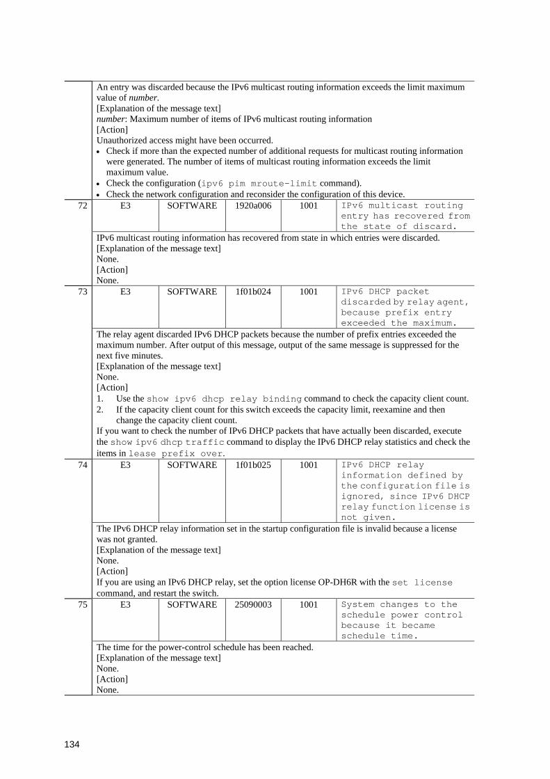
134
An entry was discarded because the IPv6 multicast routing information exceeds the limit maximum value of number. [Explanation of the message text] number: Maximum number of items of IPv6 multicast routing information [Action] Unauthorized access might have been occurred. • Check if more than the expected number of additional requests for multicast routing information
were generated. The number of items of multicast routing information exceeds the limit maximum value.
• Check the configuration (ipv6 pim mroute-limit command). • Check the network configuration and reconsider the configuration of this device.
E3 SOFTWARE 1920a006 1001 IPv6 multicast routing entry has recovered from the state of discard.
72
IPv6 multicast routing information has recovered from state in which entries were discarded. [Explanation of the message text] None. [Action] None.
E3 SOFTWARE 1f01b024 1001 IPv6 DHCP packet discarded by relay agent, because prefix entry exceeded the maximum.
73
The relay agent discarded IPv6 DHCP packets because the number of prefix entries exceeded the maximum number. After output of this message, output of the same message is suppressed for the next five minutes. [Explanation of the message text] None. [Action] 1. Use the show ipv6 dhcp relay binding command to check the capacity client count.2. If the capacity client count for this switch exceeds the capacity limit, reexamine and then
change the capacity client count. If you want to check the number of IPv6 DHCP packets that have actually been discarded, execute the show ipv6 dhcp traffic command to display the IPv6 DHCP relay statistics and check the items in lease prefix over.
E3 SOFTWARE 1f01b025 1001 IPv6 DHCP relay information defined by the configuration file is ignored, since IPv6 DHCP relay function license is not given.
74
The IPv6 DHCP relay information set in the startup configuration file is invalid because a license was not granted. [Explanation of the message text] None. [Action] If you are using an IPv6 DHCP relay, set the option license OP-DH6R with the set license command, and restart the switch.
E3 SOFTWARE 25090003 1001 System changes to the schedule power control because it became schedule time.
75
The time for the power-control schedule has been reached. [Explanation of the message text] None. [Action] None.
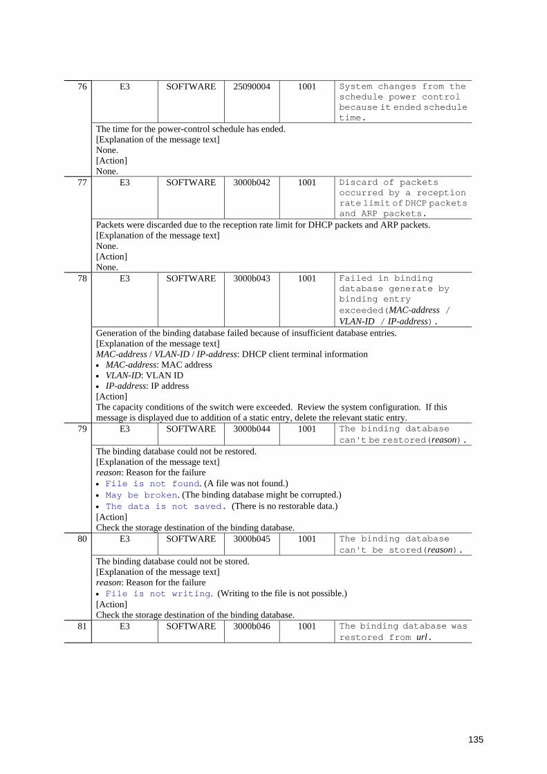
135
E3 SOFTWARE 25090004 1001 System changes from the schedule power control because it ended schedule time.
76
The time for the power-control schedule has ended. [Explanation of the message text] None. [Action] None.
E3 SOFTWARE 3000b042 1001 Discard of packets occurred by a reception rate limit of DHCP packets and ARP packets.
77
Packets were discarded due to the reception rate limit for DHCP packets and ARP packets. [Explanation of the message text] None. [Action] None.
E3 SOFTWARE 3000b043 1001 Failed in binding database generate by binding entry exceeded(MAC-address / VLAN-ID / IP-address).
78
Generation of the binding database failed because of insufficient database entries. [Explanation of the message text] MAC-address / VLAN-ID / IP-address: DHCP client terminal information • MAC-address: MAC address • VLAN-ID: VLAN ID • IP-address: IP address [Action] The capacity conditions of the switch were exceeded. Review the system configuration. If this message is displayed due to addition of a static entry, delete the relevant static entry.
E3 SOFTWARE 3000b044 1001 The binding database can't be restored(reason).
79
The binding database could not be restored. [Explanation of the message text] reason: Reason for the failure • File is not found. (A file was not found.) • May be broken. (The binding database might be corrupted.) • The data is not saved. (There is no restorable data.) [Action] Check the storage destination of the binding database.
E3 SOFTWARE 3000b045 1001 The binding database can't be stored(reason).
80
The binding database could not be stored. [Explanation of the message text] reason: Reason for the failure • File is not writing. (Writing to the file is not possible.) [Action] Check the storage destination of the binding database.
81 E3 SOFTWARE 3000b046 1001 The binding database was restored from url.

136
The binding database could not be restored. [Explanation of the message text] url: The binding database being read • previous process: The process before the restart • flash: Internal flash memory • mc: MC [Action] None.
E3 SOFTWARE 3000b047 1001 Failed in source guard setting by DHCP snooping (MAC-address / VLAN-ID / IP-address / NIF-number / port-number).
82
The terminal filter setting failed. [Explanation of the message text] MAC-address / VLAN-ID / IP-address / NIF-number / port-number: Terminal filter setting information • MAC-address: MAC address • VLAN-ID: VLAN ID • IP-address: IP address • NIF-number: NIF number • port-number: Port number [Action] The capacity conditions of the switch were exceeded. Review the system configuration.
E4 SOFTWARE 0e008021 1000 The VRRP virtual MAC address entry can't be registered at hardware tables.
83
The virtual MAC address of VRRP could not be set for the hardware. [Explanation of the message text] None. [Action] 1. Change the virtual router ID to a different value. 1. Change the VLAN ID of the VLAN for setting the virtual router to a different value.
E4 SOFTWARE 20160002 1001 The MAC-VLAN MAC Address entry can't be registered at hardware tables.
84
The MAC address that was set with the MAC VLAN configuration command could not be set for the hardware. [Explanation of the message text] None. [Action] Review the capacity limitations. However, depending on the hardware specification, the capacity cannot be set to the maximum.
E4 SOFTWARE 20400003 1001 The 802.1X Supplicant MAC address can't be registered at hardware tables.
85
The MAC address of a terminal, which had been successfully authenticated with IEEE802.1X, could not be set in the hardware table. [Explanation of the message text] None. [Action] Review the capacity limitations. However, depending on the hardware specification, the capacity cannot be set to the maximum.

137
E4 SOFTWARE 20400004 1001 The 802.1X Supplicant MAC address of MAC VLAN can't be registered at hardware tables.
86
The MAC address of a terminal, which had been successfully authenticated at a MAC VLAN with IEEE802.1X, could not be set in the hardware table. [Explanation of the message text] None. [Action] Review the capacity limitations. However, depending on the hardware specification, the capacity cannot be set to the maximum.
E4 SOFTWARE 20420002 1001 The wad MAC Address entry can't be registered at hardware tables.
87
Using the Web authentication function, the MAC address of a terminal could not be set in the hardware table. [Explanation of the message text] None. [Action] Review the capacity limitations. However, depending on the hardware specification, the capacity cannot be set to the maximum.
E4 SOFTWARE 20420003 1001 The wad MAC Address entry failed in the deletion.
88
Using the Web authentication function, the MAC address of a registered terminal could not be deleted from the hardware table. [Explanation of the message text] None. [Action] Restart L2MAC manager program (L2MacManager).
E4 SOFTWARE 20430002 1001 The macauthd MAC address entry can't be registered at hardware tables.
89
Using MAC-based authentication, the MAC address of a terminal could not be set in the hardware table. [Explanation of the message text] None. [Action] Review the capacity limitations. However, depending on the hardware specification, the capacity cannot be set to the maximum.
E4 SOFTWARE 20430003 1001 The macauthd MAC address entry failed in the deletion.
90
Using MAC-based authentication, the MAC address of a registered terminal could not be deleted from the hardware table. [Explanation of the message text] None. [Action] Restart L2MacManager.
91 E4 SOFTWARE 27000013 0000 System accounting failed (number times).
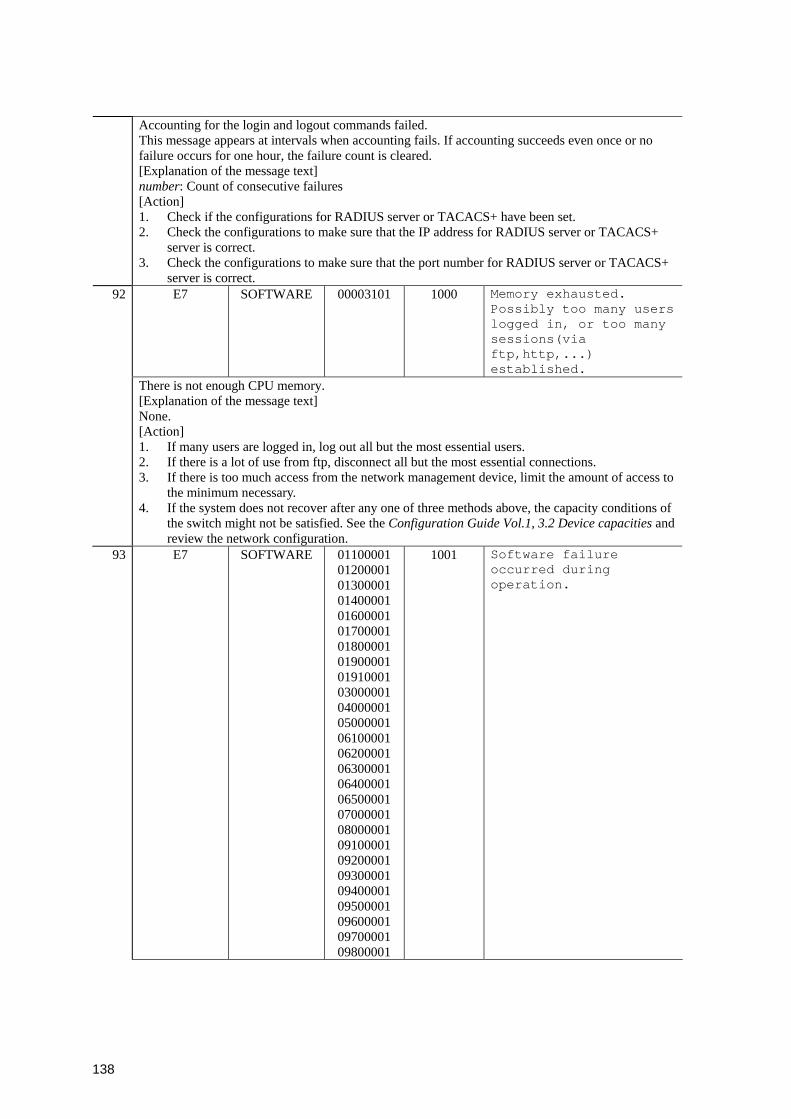
138
Accounting for the login and logout commands failed. This message appears at intervals when accounting fails. If accounting succeeds even once or no failure occurs for one hour, the failure count is cleared. [Explanation of the message text] number: Count of consecutive failures [Action] 1. Check if the configurations for RADIUS server or TACACS+ have been set. 2. Check the configurations to make sure that the IP address for RADIUS server or TACACS+
server is correct. 3. Check the configurations to make sure that the port number for RADIUS server or TACACS+
server is correct. E7 SOFTWARE 00003101 1000 Memory exhausted.
Possibly too many users logged in, or too many sessions(via ftp,http,...) established.
92
There is not enough CPU memory. [Explanation of the message text] None. [Action] 1. If many users are logged in, log out all but the most essential users. 2. If there is a lot of use from ftp, disconnect all but the most essential connections. 3. If there is too much access from the network management device, limit the amount of access to
the minimum necessary. 4. If the system does not recover after any one of three methods above, the capacity conditions of
the switch might not be satisfied. See the Configuration Guide Vol.1, 3.2 Device capacities and review the network configuration.
93 E7 SOFTWARE 01100001 01200001 01300001 01400001 01600001 01700001 01800001 01900001 01910001 03000001 04000001 05000001 06100001 06200001 06300001 06400001 06500001 07000001 08000001 09100001 09200001 09300001 09400001 09500001 09600001 09700001 09800001
1001 Software failure occurred during operation.
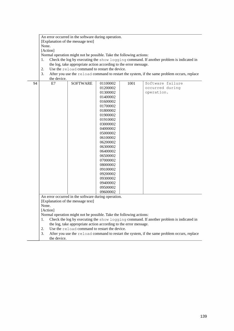
139
An error occurred in the software during operation. [Explanation of the message text] None. [Action] Normal operation might not be possible. Take the following actions: 1. Check the log by executing the show logging command. If another problem is indicated in
the log, take appropriate action according to the error message. 2. Use the reload command to restart the device. 3. After you use the reload command to restart the system, if the same problem occurs, replace
the device. 94 E7 SOFTWARE 01100002
01200002 01300002 01400002 01600002 01700002 01800002 01900002 01910002 03000002 04000002 05000002 06100002 06200002 06300002 06400002 06500002 07000002 08000002 09100002 09200002 09300002 09400002 09500002 09600002
1001 Software failure occurred during operation.
An error occurred in the software during operation. [Explanation of the message text] None. [Action] Normal operation might not be possible. Take the following actions: 1. Check the log by executing the show logging command. If another problem is indicated in
the log, take appropriate action according to the error message. 2. Use the reload command to restart the device. 3. After you use the reload command to restart the system, if the same problem occurs, replace
the device.
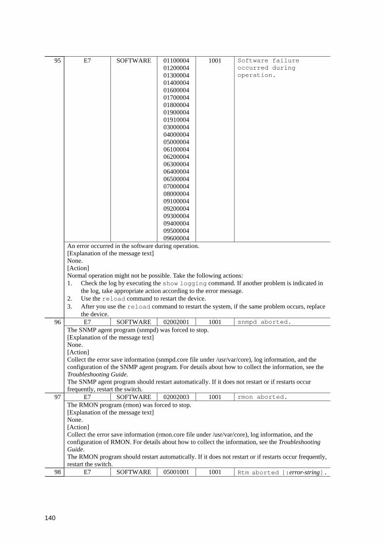
140
95 E7 SOFTWARE 01100004 01200004 01300004 01400004 01600004 01700004 01800004 01900004 01910004 03000004 04000004 05000004 06100004 06200004 06300004 06400004 06500004 07000004 08000004 09100004 09200004 09300004 09400004 09500004 09600004
1001 Software failure occurred during operation.
An error occurred in the software during operation. [Explanation of the message text] None. [Action] Normal operation might not be possible. Take the following actions: 1. Check the log by executing the show logging command. If another problem is indicated in
the log, take appropriate action according to the error message. 2. Use the reload command to restart the device. 3. After you use the reload command to restart the system, if the same problem occurs, replace
the device. E7 SOFTWARE 02002001 1001 snmpd aborted. 96
The SNMP agent program (snmpd) was forced to stop. [Explanation of the message text] None. [Action] Collect the error save information (snmpd.core file under /usr/var/core), log information, and the configuration of the SNMP agent program. For details about how to collect the information, see the Troubleshooting Guide. The SNMP agent program should restart automatically. If it does not restart or if restarts occur frequently, restart the switch.
E7 SOFTWARE 02002003 1001 rmon aborted. 97 The RMON program (rmon) was forced to stop. [Explanation of the message text] None. [Action] Collect the error save information (rmon.core file under /usr/var/core), log information, and the configuration of RMON. For details about how to collect the information, see the Troubleshooting Guide. The RMON program should restart automatically. If it does not restart or if restarts occur frequently, restart the switch.
98 E7 SOFTWARE 05001001 1001 Rtm aborted [:error-string].
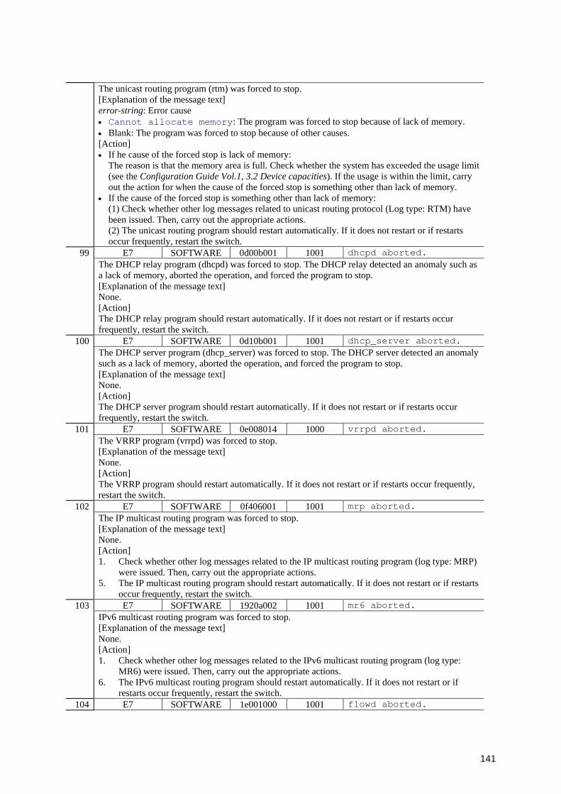
141
The unicast routing program (rtm) was forced to stop. [Explanation of the message text] error-string: Error cause • Cannot allocate memory: The program was forced to stop because of lack of memory. • Blank: The program was forced to stop because of other causes. [Action] • If he cause of the forced stop is lack of memory:
The reason is that the memory area is full. Check whether the system has exceeded the usage limit (see the Configuration Guide Vol.1, 3.2 Device capacities). If the usage is within the limit, carry out the action for when the cause of the forced stop is something other than lack of memory.
• If the cause of the forced stop is something other than lack of memory: (1) Check whether other log messages related to unicast routing protocol (Log type: RTM) have been issued. Then, carry out the appropriate actions. (2) The unicast routing program should restart automatically. If it does not restart or if restarts occur frequently, restart the switch.
E7 SOFTWARE 0d00b001 1001 dhcpd aborted. 99 The DHCP relay program (dhcpd) was forced to stop. The DHCP relay detected an anomaly such as a lack of memory, aborted the operation, and forced the program to stop. [Explanation of the message text] None. [Action] The DHCP relay program should restart automatically. If it does not restart or if restarts occur frequently, restart the switch.
E7 SOFTWARE 0d10b001 1001 dhcp_server aborted. 100 The DHCP server program (dhcp_server) was forced to stop. The DHCP server detected an anomaly such as a lack of memory, aborted the operation, and forced the program to stop. [Explanation of the message text] None. [Action] The DHCP server program should restart automatically. If it does not restart or if restarts occur frequently, restart the switch.
E7 SOFTWARE 0e008014 1000 vrrpd aborted. 101 The VRRP program (vrrpd) was forced to stop. [Explanation of the message text] None. [Action] The VRRP program should restart automatically. If it does not restart or if restarts occur frequently, restart the switch.
E7 SOFTWARE 0f406001 1001 mrp aborted. 102 The IP multicast routing program was forced to stop. [Explanation of the message text] None. [Action] 1. Check whether other log messages related to the IP multicast routing program (log type: MRP)
were issued. Then, carry out the appropriate actions. 5. The IP multicast routing program should restart automatically. If it does not restart or if restarts
occur frequently, restart the switch. E7 SOFTWARE 1920a002 1001 mr6 aborted. 103
IPv6 multicast routing program was forced to stop. [Explanation of the message text] None. [Action] 1. Check whether other log messages related to the IPv6 multicast routing program (log type:
MR6) were issued. Then, carry out the appropriate actions. 6. The IPv6 multicast routing program should restart automatically. If it does not restart or if
restarts occur frequently, restart the switch. 104 E7 SOFTWARE 1e001000 1001 flowd aborted.
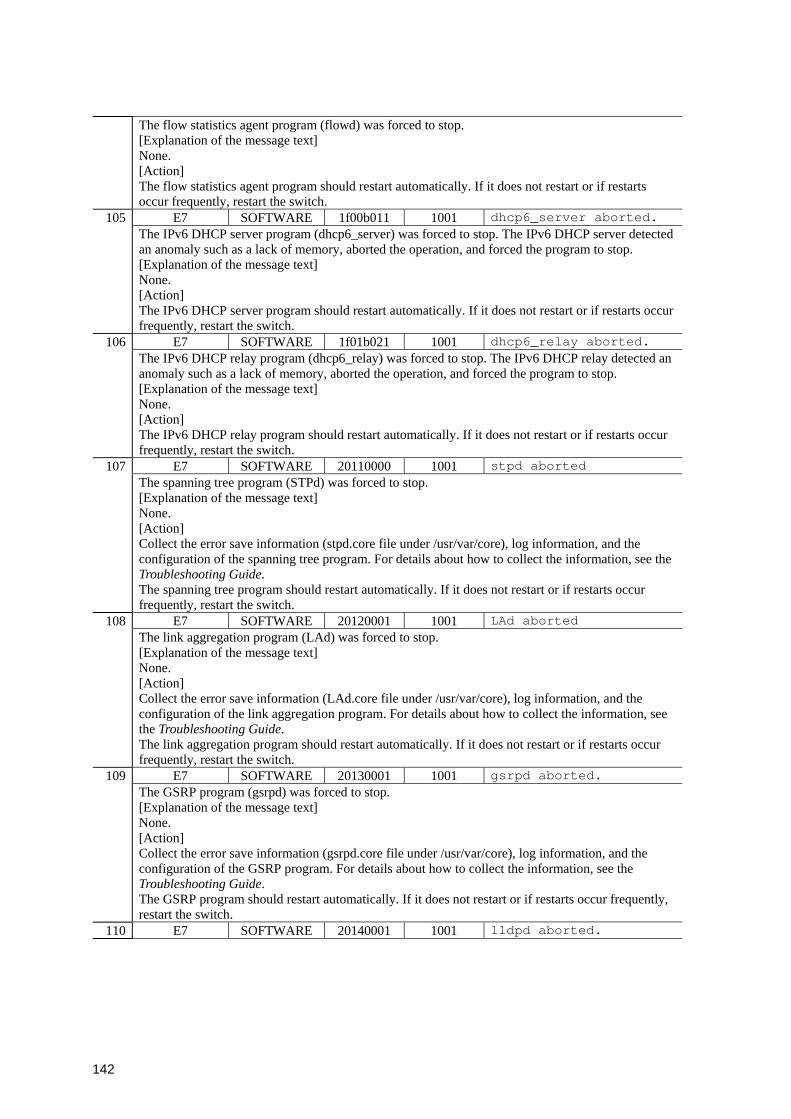
142
The flow statistics agent program (flowd) was forced to stop. [Explanation of the message text] None. [Action] The flow statistics agent program should restart automatically. If it does not restart or if restarts occur frequently, restart the switch.
E7 SOFTWARE 1f00b011 1001 dhcp6_server aborted. 105 The IPv6 DHCP server program (dhcp6_server) was forced to stop. The IPv6 DHCP server detected an anomaly such as a lack of memory, aborted the operation, and forced the program to stop. [Explanation of the message text] None. [Action] The IPv6 DHCP server program should restart automatically. If it does not restart or if restarts occur frequently, restart the switch.
E7 SOFTWARE 1f01b021 1001 dhcp6_relay aborted. 106 The IPv6 DHCP relay program (dhcp6_relay) was forced to stop. The IPv6 DHCP relay detected an anomaly such as a lack of memory, aborted the operation, and forced the program to stop. [Explanation of the message text] None. [Action] The IPv6 DHCP relay program should restart automatically. If it does not restart or if restarts occur frequently, restart the switch.
E7 SOFTWARE 20110000 1001 stpd aborted 107 The spanning tree program (STPd) was forced to stop. [Explanation of the message text] None. [Action] Collect the error save information (stpd.core file under /usr/var/core), log information, and the configuration of the spanning tree program. For details about how to collect the information, see the Troubleshooting Guide. The spanning tree program should restart automatically. If it does not restart or if restarts occur frequently, restart the switch.
E7 SOFTWARE 20120001 1001 LAd aborted 108 The link aggregation program (LAd) was forced to stop. [Explanation of the message text] None. [Action] Collect the error save information (LAd.core file under /usr/var/core), log information, and the configuration of the link aggregation program. For details about how to collect the information, see the Troubleshooting Guide. The link aggregation program should restart automatically. If it does not restart or if restarts occur frequently, restart the switch.
E7 SOFTWARE 20130001 1001 gsrpd aborted. 109 The GSRP program (gsrpd) was forced to stop. [Explanation of the message text] None. [Action] Collect the error save information (gsrpd.core file under /usr/var/core), log information, and the configuration of the GSRP program. For details about how to collect the information, see the Troubleshooting Guide. The GSRP program should restart automatically. If it does not restart or if restarts occur frequently, restart the switch.
110 E7 SOFTWARE 20140001 1001 lldpd aborted.
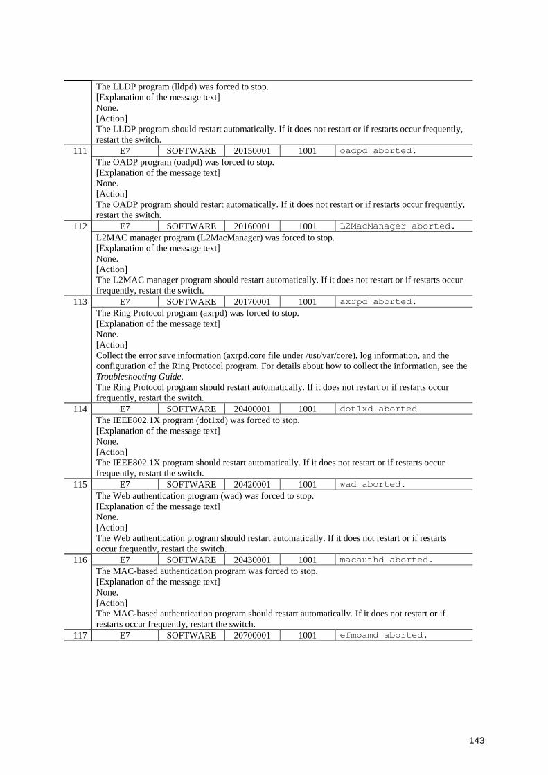
143
The LLDP program (lldpd) was forced to stop. [Explanation of the message text] None. [Action] The LLDP program should restart automatically. If it does not restart or if restarts occur frequently, restart the switch.
E7 SOFTWARE 20150001 1001 oadpd aborted. 111 The OADP program (oadpd) was forced to stop. [Explanation of the message text] None. [Action] The OADP program should restart automatically. If it does not restart or if restarts occur frequently, restart the switch.
E7 SOFTWARE 20160001 1001 L2MacManager aborted. 112 L2MAC manager program (L2MacManager) was forced to stop. [Explanation of the message text] None. [Action] The L2MAC manager program should restart automatically. If it does not restart or if restarts occur frequently, restart the switch.
E7 SOFTWARE 20170001 1001 axrpd aborted. 113 The Ring Protocol program (axrpd) was forced to stop.
[Explanation of the message text] None. [Action] Collect the error save information (axrpd.core file under /usr/var/core), log information, and the configuration of the Ring Protocol program. For details about how to collect the information, see the Troubleshooting Guide. The Ring Protocol program should restart automatically. If it does not restart or if restarts occur frequently, restart the switch.
E7 SOFTWARE 20400001 1001 dot1xd aborted 114 The IEEE802.1X program (dot1xd) was forced to stop.
[Explanation of the message text] None. [Action] The IEEE802.1X program should restart automatically. If it does not restart or if restarts occur frequently, restart the switch.
E7 SOFTWARE 20420001 1001 wad aborted. 115 The Web authentication program (wad) was forced to stop. [Explanation of the message text] None. [Action] The Web authentication program should restart automatically. If it does not restart or if restarts occur frequently, restart the switch.
E7 SOFTWARE 20430001 1001 macauthd aborted. 116 The MAC-based authentication program was forced to stop. [Explanation of the message text] None. [Action] The MAC-based authentication program should restart automatically. If it does not restart or if restarts occur frequently, restart the switch.
117 E7 SOFTWARE 20700001 1001 efmoamd aborted.

144
The IEEE802.3ah/OAM program (efmoamd) was forced to stop. [Explanation of the message text] None. [Action] The IEEE802.3ah/OAM program should restart automatically. If it does not restart if restarts occur frequently, restart the switch.
E7 SOFTWARE 20800001 1001 l2ldd aborted. 118 The L2 loop detection program (l2ldd) was forced to stop. [Explanation of the message text] None. [Action] The L2 loop detection manager program should restart automatically. If it does not restart or if restarts occur frequently, restart the switch.
E7 SOFTWARE 20900001 1001 cfmd aborted. 119 The CFM program (cfmd) was forced to stop. [Explanation of the message text] None. [Action] Collect the error save information (cfmd.core file under /usr/var/core), log information, and the configuration of the CFM program. For details about how to collect the information, see the Troubleshooting Guide. The CFM program should restart automatically. If it does not restart or if restarts occur frequently, restart the switch.
E7 SOFTWARE 21000001 1001 snoopd aborted. 120 The IGMP snooping/MLD snooping program (snoopd) was forced to stop. [Explanation of the message text] None. [Action] The IGMP snooping/MLD snooping program should restart automatically. If it does not restart or if restarts occur frequently, restart the switch.
E7 SOFTWARE 25300000 1001 nimd aborted. 121 The network interface manager program (nimd) was forced to stop. [Explanation of the message text] None. [Action] The network interface manager program should restart automatically. If it does not restart or if restarts occur frequently, restart the switch.
E7 SOFTWARE 27000001 0000 accountingd aborted. 122 The accounting program (accountingd) was forced to stop. [Explanation of the message text] None. [Action] Collect the error save information (acctd.core file under /usr/var/core), log information, and the configuration of the accounting program. For details about how to collect the information, see the Troubleshooting Guide. The accounting program should restart automatically. If it does not restart or if restarts occur frequently, restart the switch.
123 E7 SOFTWARE 27000011 0000 System accounting temporary stopped because accounting event congestion detected.
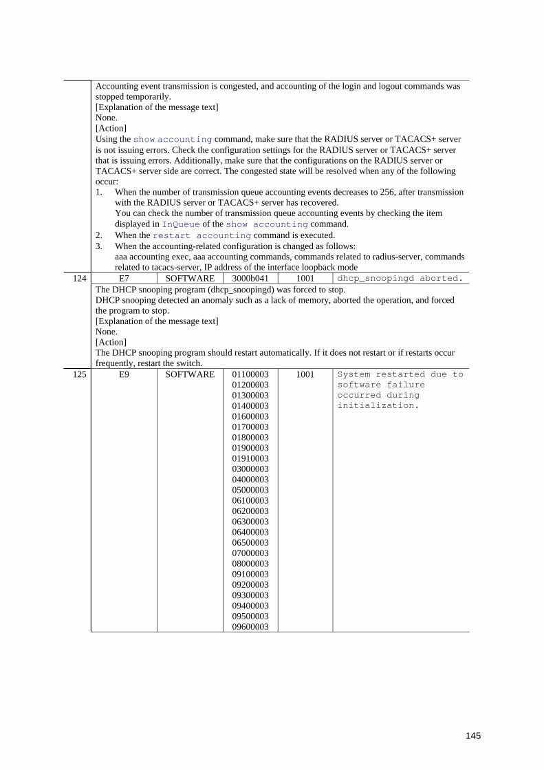
145
Accounting event transmission is congested, and accounting of the login and logout commands was stopped temporarily. [Explanation of the message text] None. [Action] Using the show accounting command, make sure that the RADIUS server or TACACS+ server is not issuing errors. Check the configuration settings for the RADIUS server or TACACS+ server that is issuing errors. Additionally, make sure that the configurations on the RADIUS server or TACACS+ server side are correct. The congested state will be resolved when any of the following occur: 1. When the number of transmission queue accounting events decreases to 256, after transmission
with the RADIUS server or TACACS+ server has recovered. You can check the number of transmission queue accounting events by checking the item displayed in InQueue of the show accounting command.
2. When the restart accounting command is executed. 3. When the accounting-related configuration is changed as follows:
aaa accounting exec, aaa accounting commands, commands related to radius-server, commands related to tacacs-server, IP address of the interface loopback mode E7 SOFTWARE 3000b041 1001 dhcp_snoopingd aborted.124
The DHCP snooping program (dhcp_snoopingd) was forced to stop. DHCP snooping detected an anomaly such as a lack of memory, aborted the operation, and forced the program to stop. [Explanation of the message text] None. [Action] The DHCP snooping program should restart automatically. If it does not restart or if restarts occur frequently, restart the switch.
125 E9 SOFTWARE 01100003 01200003 01300003 01400003 01600003 01700003 01800003 01900003 01910003 03000003 04000003 05000003 06100003 06200003 06300003 06400003 06500003 07000003 08000003 09100003 09200003 09300003 09400003 09500003 09600003
1001 System restarted due to software failure occurred during initialization.
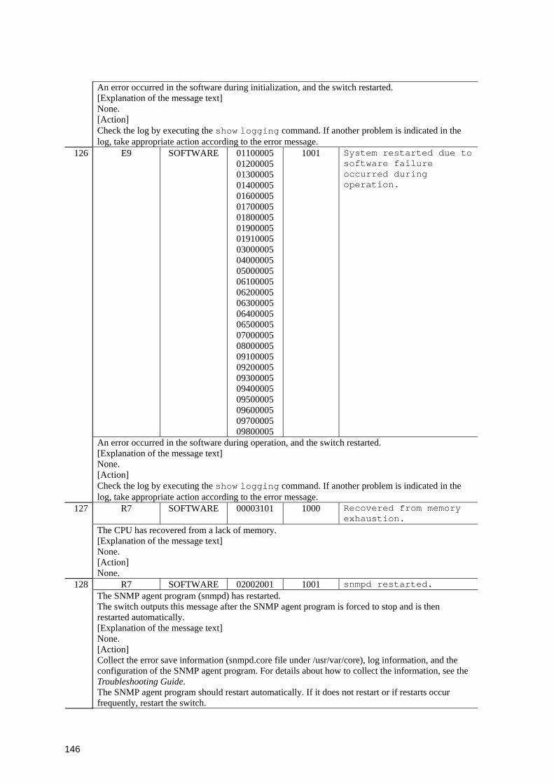
146
An error occurred in the software during initialization, and the switch restarted. [Explanation of the message text] None. [Action] Check the log by executing the show logging command. If another problem is indicated in the log, take appropriate action according to the error message.
126 E9 SOFTWARE 01100005 01200005 01300005 01400005 01600005 01700005 01800005 01900005 01910005 03000005 04000005 05000005 06100005 06200005 06300005 06400005 06500005 07000005 08000005 09100005 09200005 09300005 09400005 09500005 09600005 09700005 09800005
1001 System restarted due to software failure occurred during operation.
An error occurred in the software during operation, and the switch restarted. [Explanation of the message text] None. [Action] Check the log by executing the show logging command. If another problem is indicated in the log, take appropriate action according to the error message.
R7 SOFTWARE 00003101 1000 Recovered from memory exhaustion.
127
The CPU has recovered from a lack of memory. [Explanation of the message text] None. [Action] None.
R7 SOFTWARE 02002001 1001 snmpd restarted. 128 The SNMP agent program (snmpd) has restarted. The switch outputs this message after the SNMP agent program is forced to stop and is then restarted automatically. [Explanation of the message text] None. [Action] Collect the error save information (snmpd.core file under /usr/var/core), log information, and the configuration of the SNMP agent program. For details about how to collect the information, see the Troubleshooting Guide. The SNMP agent program should restart automatically. If it does not restart or if restarts occur frequently, restart the switch.
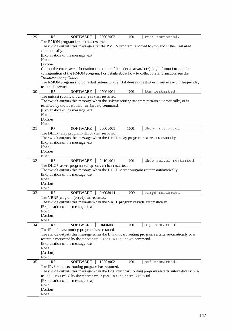
147
R7 SOFTWARE 02002003 1001 rmon restarted. 129 The RMON program (rmon) has restarted. The switch outputs this message after the RMON program is forced to stop and is then restarted automatically. [Explanation of the message text] None. [Action] Collect the error save information (rmon.core file under /usr/var/core), log information, and the configuration of the RMON program. For details about how to collect the information, see the Troubleshooting Guide. The RMON program should restart automatically. If it does not restart or if restarts occur frequently, restart the switch.
R7 SOFTWARE 05001001 1001 Rtm restarted. 130 The unicast routing program (rtm) has restarted. The switch outputs this message when the unicast routing program restarts automatically, or is restarted by the restart unicast command. [Explanation of the message text] None. [Action] None.
R7 SOFTWARE 0d00b001 1001 dhcpd restarted. 131 The DHCP relay program (dhcpd) has restarted. The switch outputs this message when the DHCP relay program restarts automatically. [Explanation of the message text] None. [Action] None.
R7 SOFTWARE 0d10b001 1001 dhcp_server restarted. 132 The DHCP server program (dhcp_server) has restarted. The switch outputs this message when the DHCP server program restarts automatically. [Explanation of the message text] None. [Action] None.
R7 SOFTWARE 0e008014 1000 vrrpd restarted. 133 The VRRP program (vrrpd) has restarted. The switch outputs this message when the VRRP program restarts automatically. [Explanation of the message text] None. [Action] None.
R7 SOFTWARE 0f406001 1001 mrp restarted. 134 The IP multicast routing program has restarted. The switch outputs this message when the IP multicast routing program restarts automatically or a restart is requested by the restart IPv4-multicast command. [Explanation of the message text] None. [Action] None.
R7 SOFTWARE 1920a002 1001 mr6 restarted. 135 The IPv6 multicast routing program has restarted. The switch outputs this message when the IPv6 multicast routing program restarts automatically or a restart is requested by the restart ipv6-multicast command. [Explanation of the message text] None. [Action] None.
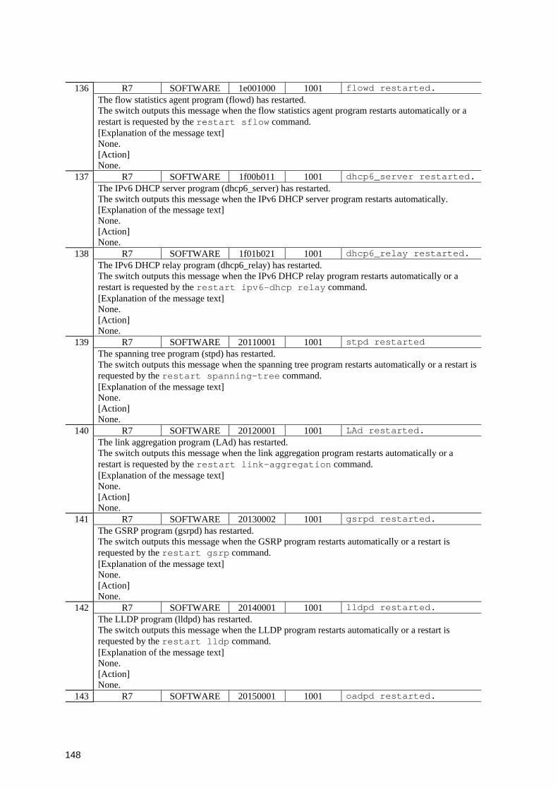
148
R7 SOFTWARE 1e001000 1001 flowd restarted. 136 The flow statistics agent program (flowd) has restarted. The switch outputs this message when the flow statistics agent program restarts automatically or a restart is requested by the restart sflow command. [Explanation of the message text] None. [Action] None.
R7 SOFTWARE 1f00b011 1001 dhcp6_server restarted.137 The IPv6 DHCP server program (dhcp6_server) has restarted. The switch outputs this message when the IPv6 DHCP server program restarts automatically. [Explanation of the message text] None. [Action] None.
R7 SOFTWARE 1f01b021 1001 dhcp6_relay restarted. 138 The IPv6 DHCP relay program (dhcp6_relay) has restarted. The switch outputs this message when the IPv6 DHCP relay program restarts automatically or a restart is requested by the restart ipv6-dhcp relay command. [Explanation of the message text] None. [Action] None.
R7 SOFTWARE 20110001 1001 stpd restarted 139 The spanning tree program (stpd) has restarted. The switch outputs this message when the spanning tree program restarts automatically or a restart is requested by the restart spanning-tree command. [Explanation of the message text] None. [Action] None.
R7 SOFTWARE 20120001 1001 LAd restarted. 140 The link aggregation program (LAd) has restarted. The switch outputs this message when the link aggregation program restarts automatically or a restart is requested by the restart link-aggregation command. [Explanation of the message text] None. [Action] None.
R7 SOFTWARE 20130002 1001 gsrpd restarted. 141 The GSRP program (gsrpd) has restarted. The switch outputs this message when the GSRP program restarts automatically or a restart is requested by the restart gsrp command. [Explanation of the message text] None. [Action] None.
R7 SOFTWARE 20140001 1001 lldpd restarted. 142 The LLDP program (lldpd) has restarted. The switch outputs this message when the LLDP program restarts automatically or a restart is requested by the restart lldp command. [Explanation of the message text] None. [Action] None.
143 R7 SOFTWARE 20150001 1001 oadpd restarted.
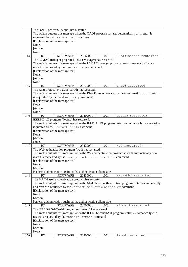
149
The OADP program (oadpd) has restarted. The switch outputs this message when the OADP program restarts automatically or a restart is requested by the restart oadp command. [Explanation of the message text] None. [Action] None.
R7 SOFTWARE 20160001 1001 L2MacManager restarted.144 The L2MAC manager program (L2MacManager) has restarted. The switch outputs this message when the L2MAC manager program restarts automatically or a restart is requested by the restart vlan command. [Explanation of the message text] None. [Action] None.
R7 SOFTWARE 20170001 1001 axrpd restarted. 145 The Ring Protocol program (axrpd) has restarted. The switch outputs this message when the Ring Protocol program restarts automatically or a restart is requested by the restart axrp command. [Explanation of the message text] None. [Action] None.
R7 SOFTWARE 20400001 1001 dot1xd restarted. 146 IEEE802.1X program (dot1xd) has restarted. The switch outputs this message when the IEEE802.1X program restarts automatically or a restart is requested by the restart dot1x command. [Explanation of the message text] None. [Action] None.
R7 SOFTWARE 20420001 1001 wad restarted. 147 The Web authentication program (wad) has restarted. The switch outputs this message when the Web authentication program restarts automatically or a restart is requested by the restart web-authentication command. [Explanation of the message text] None. [Action] Perform authentication again on the authentication client side.
R7 SOFTWARE 20430001 1001 macauthd restarted. 148 The MAC-based authentication program has restarted. The switch outputs this message when the MAC-based authentication program restarts automatically or a restart is requested by the restart mac-authentication command. [Explanation of the message text] None. [Action] Perform authentication again on the authentication client side.
R7 SOFTWARE 20700001 1001 efmoamd restarted. 149 The IEEE802.3ah/OAM program (efmoamd) has restarted. The switch outputs this message when the IEEE802.3ah/OAM program restarts automatically or a restart is requested by the restart efmoam command. [Explanation of the message text] None. [Action] None.
150 R7 SOFTWARE 20800001 1001 l2ldd restarted.
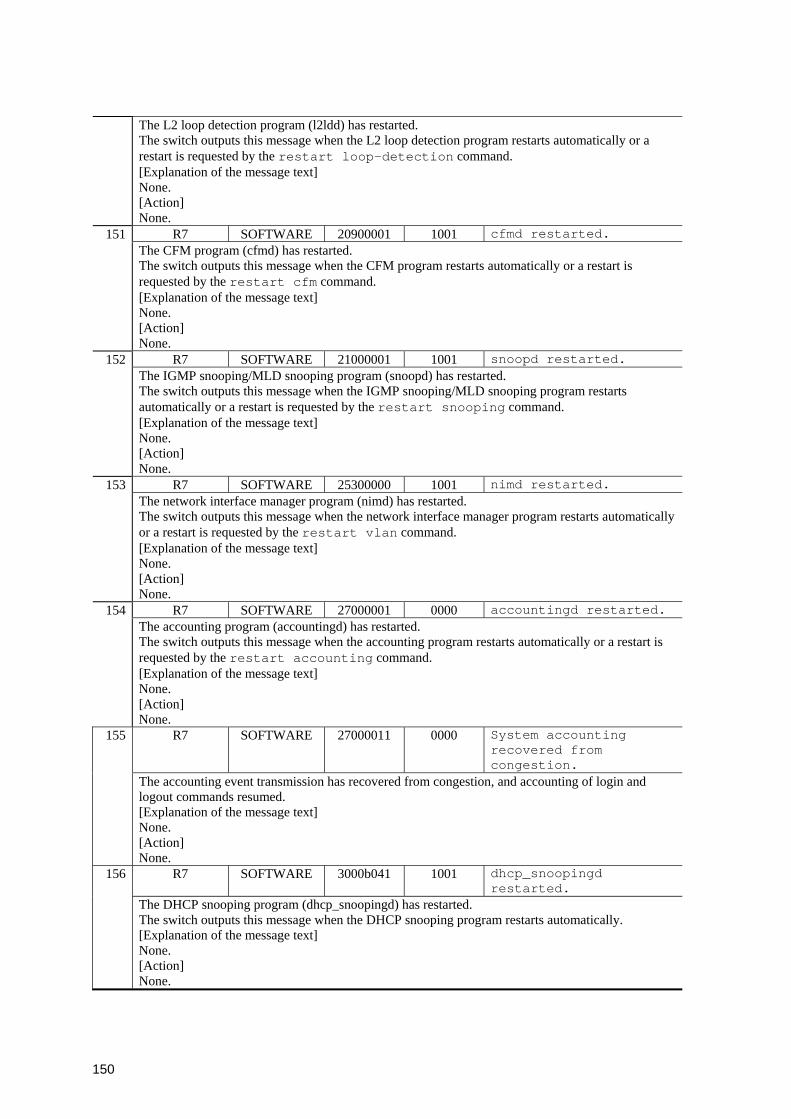
150
The L2 loop detection program (l2ldd) has restarted. The switch outputs this message when the L2 loop detection program restarts automatically or a restart is requested by the restart loop-detection command. [Explanation of the message text] None. [Action] None.
R7 SOFTWARE 20900001 1001 cfmd restarted. 151 The CFM program (cfmd) has restarted. The switch outputs this message when the CFM program restarts automatically or a restart is requested by the restart cfm command. [Explanation of the message text] None. [Action] None.
R7 SOFTWARE 21000001 1001 snoopd restarted. 152 The IGMP snooping/MLD snooping program (snoopd) has restarted. The switch outputs this message when the IGMP snooping/MLD snooping program restarts automatically or a restart is requested by the restart snooping command. [Explanation of the message text] None. [Action] None.
R7 SOFTWARE 25300000 1001 nimd restarted. 153 The network interface manager program (nimd) has restarted. The switch outputs this message when the network interface manager program restarts automatically or a restart is requested by the restart vlan command. [Explanation of the message text] None. [Action] None.
R7 SOFTWARE 27000001 0000 accountingd restarted. 154 The accounting program (accountingd) has restarted. The switch outputs this message when the accounting program restarts automatically or a restart is requested by the restart accounting command. [Explanation of the message text] None. [Action] None.
R7 SOFTWARE 27000011 0000 System accounting recovered from congestion.
155
The accounting event transmission has recovered from congestion, and accounting of login and logout commands resumed. [Explanation of the message text] None. [Action] None.
R7 SOFTWARE 3000b041 1001 dhcp_snoopingd restarted.
156
The DHCP snooping program (dhcp_snoopingd) has restarted. The switch outputs this message when the DHCP snooping program restarts automatically. [Explanation of the message text] None. [Action] None.
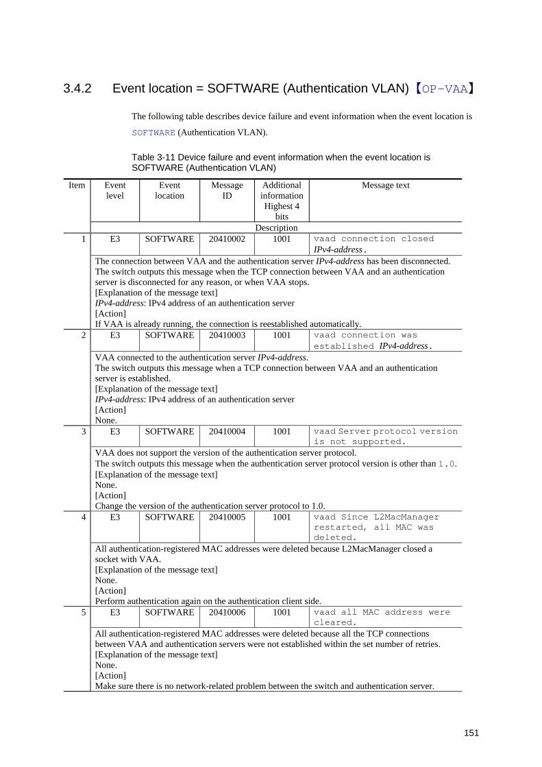
151
3.4.2 Event location = SOFTWARE (Authentication VLAN)【OP-VAA】
The following table describes device failure and event information when the event location is
SOFTWARE (Authentication VLAN).
Table 3-11 Device failure and event information when the event location is SOFTWARE (Authentication VLAN)
Event level
Event location
Message ID
Additional informationHighest 4
bits
Message text Item
Description E3 SOFTWARE 20410002 1001 vaad connection closed
IPv4-address. 1
The connection between VAA and the authentication server IPv4-address has been disconnected. The switch outputs this message when the TCP connection between VAA and an authentication server is disconnected for any reason, or when VAA stops. [Explanation of the message text] IPv4-address: IPv4 address of an authentication server [Action] If VAA is already running, the connection is reestablished automatically.
E3 SOFTWARE 20410003 1001 vaad connection was established IPv4-address.
2
VAA connected to the authentication server IPv4-address. The switch outputs this message when a TCP connection between VAA and an authentication server is established. [Explanation of the message text] IPv4-address: IPv4 address of an authentication server [Action] None.
E3 SOFTWARE 20410004 1001 vaad Server protocol version is not supported.
3
VAA does not support the version of the authentication server protocol. The switch outputs this message when the authentication server protocol version is other than 1.0.[Explanation of the message text] None. [Action] Change the version of the authentication server protocol to 1.0.
E3 SOFTWARE 20410005 1001 vaad Since L2MacManager restarted, all MAC was deleted.
4
All authentication-registered MAC addresses were deleted because L2MacManager closed a socket with VAA. [Explanation of the message text] None. [Action] Perform authentication again on the authentication client side.
E3 SOFTWARE 20410006 1001 vaad all MAC address were cleared.
5
All authentication-registered MAC addresses were deleted because all the TCP connections between VAA and authentication servers were not established within the set number of retries. [Explanation of the message text] None. [Action] Make sure there is no network-related problem between the switch and authentication server.

152
E3 SOFTWARE 20410007 1001 vaad The socket with L2MacManager was closed.
6
The socket between VAA and L2MacManager was closed. [Explanation of the message text] None. [Action] If this error occurs frequently, restart L2MacManager.
E3 SOFTWARE 20410012 1001 VAA information defined by the configuration file is ignored, since VAA function license is not given.
7
VAA information set in the startup configuration file is invalid because a license was not granted. [Explanation of the message text] None. [Action] Set the option license OP-VAA by using the set license command, and then restart the switch.
E4 SOFTWARE 20410008 1001 The vaad MAC Address entry can't be registered at hardware tables.
8
Using the VAA function, the MAC address of a terminal could not be set in the hardware table. [Explanation of the message text] None. [Action] Review the capacity limitations. However, depending on the hardware specification, the capacity cannot be set to the maximum.
E4 SOFTWARE 20410009 1001 vaad failed to get configuration data.
9
Retrieval of VAA function configuration data inside a switch failed. [Explanation of the message text] None. [Action] Delete the configuration of the VAA functionality, and then reset the VAA configuration.
E4 SOFTWARE 20410010 1001 vaad failed to make temporary file.
10
Creation of a VAA-function temporary file inside a switch failed. [Explanation of the message text] None. [Action] Delete the configuration of the VAA functionality, and then reset the VAA configuration.
E4 SOFTWARE 20410011 1001 vaad was not able to get enough memory.
11
Sufficient VAA memory failed to be reserved because switch memory capacity is insufficient. [Explanation of the message text] None. [Action] Delete the configuration of the VAA functionality, and then reset the VAA configuration.
E7 SOFTWARE 20410001 1001 vaad aborted. 12 The VAA program (vaad) was forced to stop. [Explanation of the message text] None. [Action] The VAA program should restart automatically. If it does not restart or if restarts occur frequently, restart the switch.
13 R7 SOFTWARE 20410001 1001 vaad restarted.

153
The VAA program (vaad) has restarted. The switch outputs this message when the VAA program restarts automatically or a restart is requested by the restart vaa command. [Explanation of the message text] None. [Action] Perform authentication again on the authentication client side.
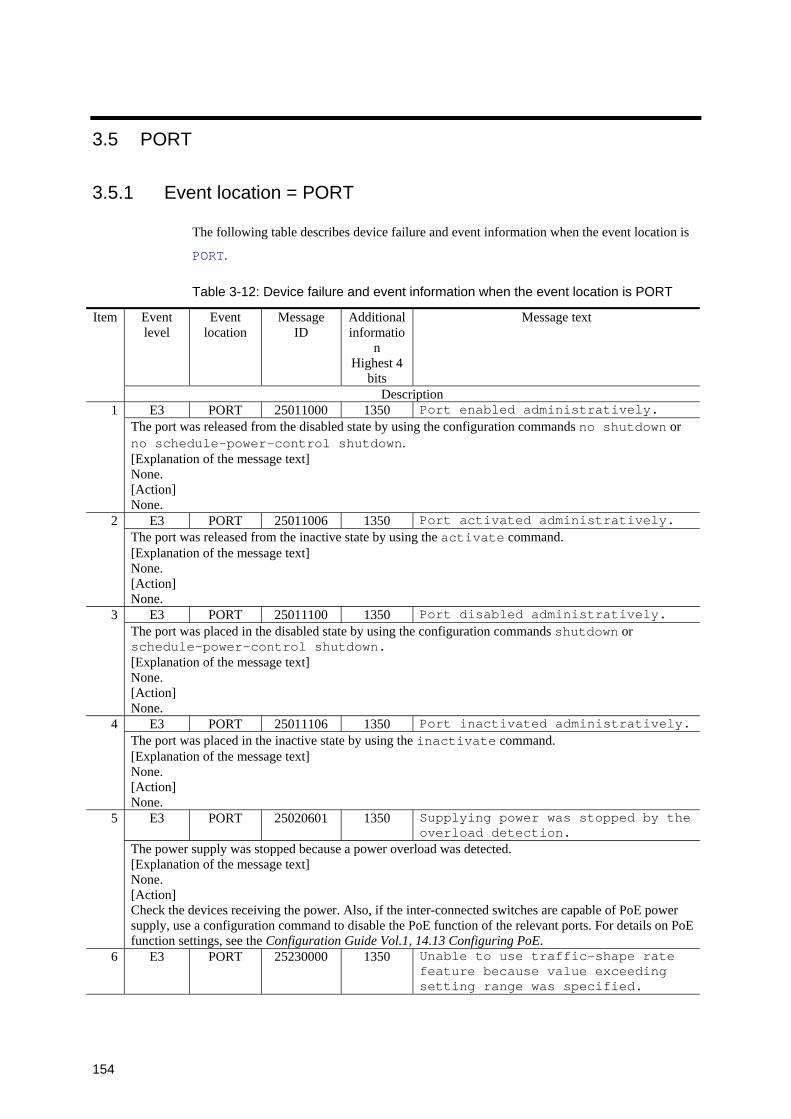
154
3.5 PORT
3.5.1 Event location = PORT
The following table describes device failure and event information when the event location is
PORT.
Table 3-12: Device failure and event information when the event location is PORT
Event level
Event location
Message ID
Additional informatio
n Highest 4
bits
Message text Item
Description E3 PORT 25011000 1350 Port enabled administratively. 1
The port was released from the disabled state by using the configuration commands no shutdown or no schedule-power-control shutdown. [Explanation of the message text] None. [Action] None.
E3 PORT 25011006 1350 Port activated administratively. 2 The port was released from the inactive state by using the activate command. [Explanation of the message text] None. [Action] None.
E3 PORT 25011100 1350 Port disabled administratively. 3 The port was placed in the disabled state by using the configuration commands shutdown or schedule-power-control shutdown. [Explanation of the message text] None. [Action] None.
E3 PORT 25011106 1350 Port inactivated administratively.4 The port was placed in the inactive state by using the inactivate command. [Explanation of the message text] None. [Action] None.
E3 PORT 25020601 1350 Supplying power was stopped by the overload detection.
5
The power supply was stopped because a power overload was detected. [Explanation of the message text] None. [Action] Check the devices receiving the power. Also, if the inter-connected switches are capable of PoE power supply, use a configuration command to disable the PoE function of the relevant ports. For details on PoE function settings, see the Configuration Guide Vol.1, 14.13 Configuring PoE.
6 E3 PORT 25230000 1350 Unable to use traffic-shape rate feature because value exceeding setting range was specified.
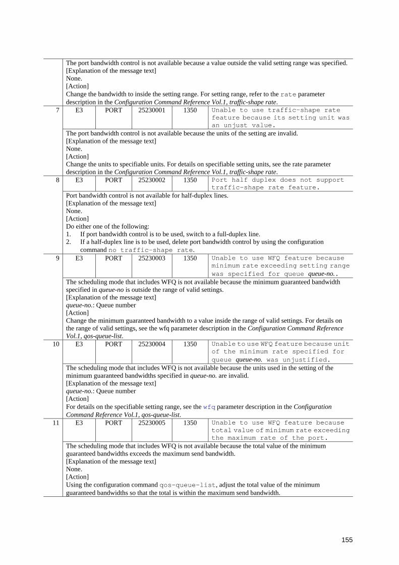
155
The port bandwidth control is not available because a value outside the valid setting range was specified.[Explanation of the message text] None. [Action] Change the bandwidth to inside the setting range. For setting range, refer to the rate parameter description in the Configuration Command Reference Vol.1, traffic-shape rate.
E3 PORT 25230001 1350 Unable to use traffic-shape rate feature because its setting unit was an unjust value.
7
The port bandwidth control is not available because the units of the setting are invalid. [Explanation of the message text] None. [Action] Change the units to specifiable units. For details on specifiable setting units, see the rate parameter description in the Configuration Command Reference Vol.1, traffic-shape rate.
E3 PORT 25230002 1350 Port half duplex does not support traffic-shape rate feature.
8
Port bandwidth control is not available for half-duplex lines. [Explanation of the message text] None. [Action] Do either one of the following: 1. If port bandwidth control is to be used, switch to a full-duplex line. 2. If a half-duplex line is to be used, delete port bandwidth control by using the configuration
command no traffic-shape rate. E3 PORT 25230003 1350 Unable to use WFQ feature because
minimum rate exceeding setting range was specified for queue queue-no..
9
The scheduling mode that includes WFQ is not available because the minimum guaranteed bandwidth specified in queue-no is outside the range of valid settings. [Explanation of the message text] queue-no.: Queue number [Action] Change the minimum guaranteed bandwidth to a value inside the range of valid settings. For details on the range of valid settings, see the wfq parameter description in the Configuration Command Reference Vol.1, qos-queue-list.
E3 PORT 25230004 1350 Unable to use WFQ feature because unit of the minimum rate specified for queue queue-no. was unjustified.
10
The scheduling mode that includes WFQ is not available because the units used in the setting of the minimum guaranteed bandwidths specified in queue-no. are invalid. [Explanation of the message text] queue-no.: Queue number [Action] For details on the specifiable setting range, see the wfq parameter description in the Configuration Command Reference Vol.1, qos-queue-list.
E3 PORT 25230005 1350 Unable to use WFQ feature because total value of minimum rate exceeding the maximum rate of the port.
11
The scheduling mode that includes WFQ is not available because the total value of the minimum guaranteed bandwidths exceeds the maximum send bandwidth. [Explanation of the message text] None. [Action] Using the configuration command qos-queue-list, adjust the total value of the minimum guaranteed bandwidths so that the total is within the maximum send bandwidth.

156
E3 PORT 25230006 1350 Port half duplex does not support WFQ feature.
12
The scheduling mode that includes WFQ is not available for half-duplex lines. [Explanation of the message text] None. [Action] Do either of the following: 1. If WFQ is to be used in the scheduling mode, switch to a full-duplex line. 2. If a half-duplex line is to be used, switch to a scheduling mode that does not include WFQ by using
the configuration commands qos-queue-group and qos-queue-list. E4 PORT 25011001 1350 Port up. 13
The port is up. [Explanation of the message text] None. [Action] None.
E4 PORT 25011002 1350 Transceiver connected. 14 A transceiver insertion was detected. [Explanation of the message text] None. [Action] None.
E4 PORT 25011101 1350 Error detected on the port. 15 Errors were detected at the ports. [Explanation of the message text] None. [Action] For 10Base-T, 100Base-TX, or 1000Base-T: 1. Make sure the specified cables are properly connected. 2. Make sure that startup of the partner switch has finished. 3. Execute the test interfaces command, and make sure that the switches and cables have no
problem. For 100BASE-FX, 1000BASE-X, or 10GBASE-R: 1. Make sure that the specified cables are properly connected. Make sure that the end sections of the
cables are clean. If they are dirty, clean them. 2. If you are using an optical attenuator, check the attenuation value. 3. Make sure that startup of the partner switch has completed. 4. Execute the test interfaces command, and make sure that the switches and cables have no
problem. E4 PORT 25011102 1350 Transceiver notconnected. 16
A transceiver removal was detected. [Explanation of the message text] None. [Action] Insert the transceiver properly.
E4 PORT 25011103 1350 Auto negotiation failed. 17 Auto negotiation has failed. [Explanation of the message text] None. [Action] • Check the auto negotiation status. • Execute the test interfaces command, and make sure that the cables have no problem. • If the devices and the cables are normal, check the destination devices.
18 E4 PORT 25011104 1350 Many failures occurred in receiving frames to the targeted port due to the port troubles. Execute the Line tests to check the port condition.
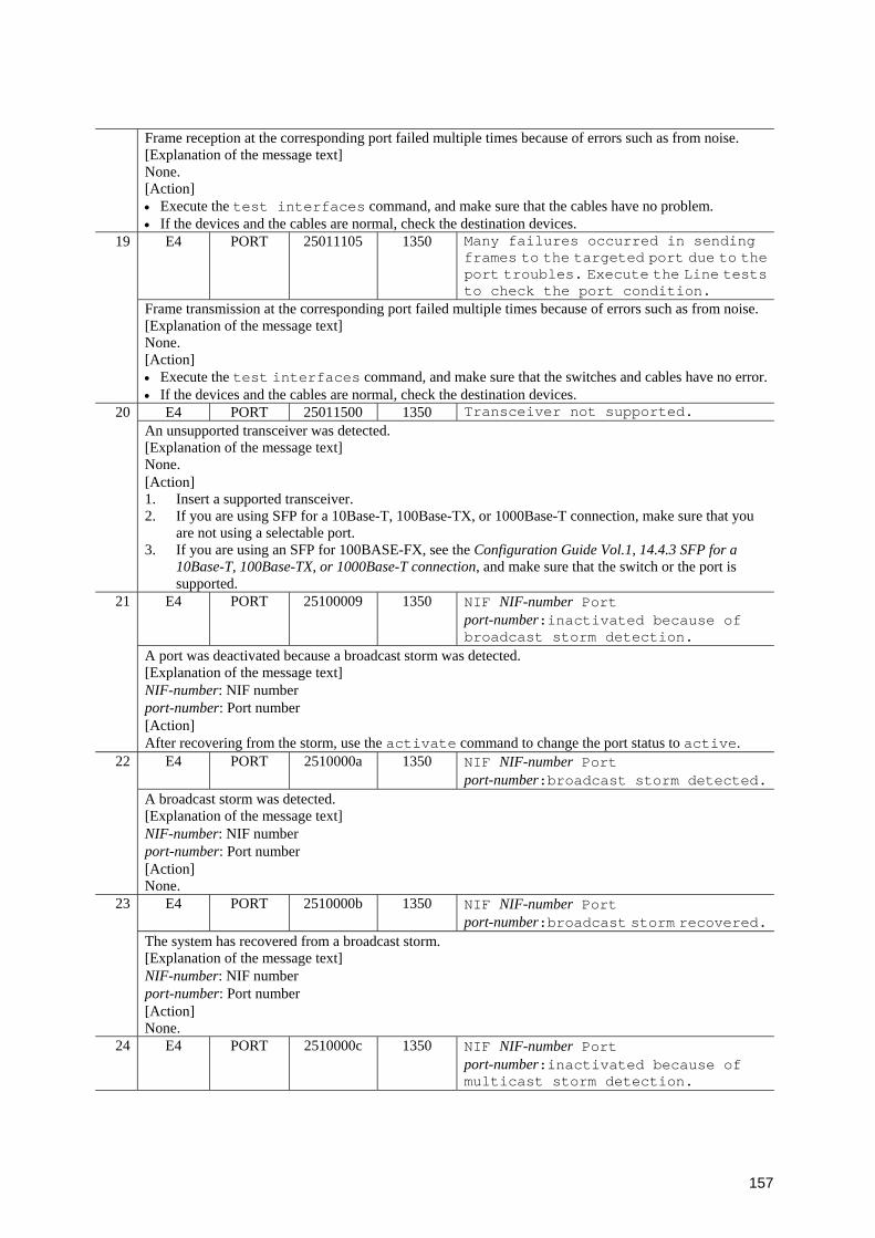
157
Frame reception at the corresponding port failed multiple times because of errors such as from noise. [Explanation of the message text] None. [Action] • Execute the test interfaces command, and make sure that the cables have no problem. • If the devices and the cables are normal, check the destination devices.
E4 PORT 25011105 1350 Many failures occurred in sending frames to the targeted port due to the port troubles. Execute the Line tests to check the port condition.
19
Frame transmission at the corresponding port failed multiple times because of errors such as from noise. [Explanation of the message text] None. [Action] • Execute the test interfaces command, and make sure that the switches and cables have no error.• If the devices and the cables are normal, check the destination devices.
E4 PORT 25011500 1350 Transceiver not supported. 20 An unsupported transceiver was detected. [Explanation of the message text] None. [Action] 1. Insert a supported transceiver. 2. If you are using SFP for a 10Base-T, 100Base-TX, or 1000Base-T connection, make sure that you
are not using a selectable port. 3. If you are using an SFP for 100BASE-FX, see the Configuration Guide Vol.1, 14.4.3 SFP for a
10Base-T, 100Base-TX, or 1000Base-T connection, and make sure that the switch or the port is supported.
E4 PORT 25100009 1350 NIF NIF-number Port port-number:inactivated because of broadcast storm detection.
21
A port was deactivated because a broadcast storm was detected. [Explanation of the message text] NIF-number: NIF number port-number: Port number [Action] After recovering from the storm, use the activate command to change the port status to active.
E4 PORT 2510000a 1350 NIF NIF-number Port port-number:broadcast storm detected.
22
A broadcast storm was detected. [Explanation of the message text] NIF-number: NIF number port-number: Port number [Action] None.
E4 PORT 2510000b 1350 NIF NIF-number Port port-number:broadcast storm recovered.
23
The system has recovered from a broadcast storm. [Explanation of the message text] NIF-number: NIF number port-number: Port number [Action] None.
24 E4 PORT 2510000c 1350 NIF NIF-number Port port-number:inactivated because of multicast storm detection.
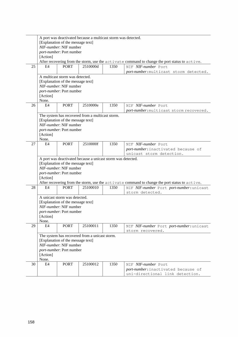
158
A port was deactivated because a multicast storm was detected. [Explanation of the message text] NIF-number: NIF number port-number: Port number [Action] After recovering from the storm, use the activate command to change the port status to active.
E4 PORT 2510000d 1350 NIF NIF-number Port port-number:multicast storm detected.
25
A multicast storm was detected. [Explanation of the message text] NIF-number: NIF number port-number: Port number [Action] None.
E4 PORT 2510000e 1350 NIF NIF-number Port port-number:multicast storm recovered.
26
The system has recovered from a multicast storm. [Explanation of the message text] NIF-number: NIF number port-number: Port number [Action] None.
E4 PORT 2510000f 1350 NIF NIF-number Port port-number:inactivated because of unicast storm detection.
27
A port was deactivated because a unicast storm was detected. [Explanation of the message text] NIF-number: NIF number port-number: Port number [Action] After recovering from the storm, use the activate command to change the port status to active.
E4 PORT 25100010 1350 NIF NIF-number Port port-number:unicast storm detected.
28
A unicast storm was detected. [Explanation of the message text] NIF-number: NIF number port-number: Port number [Action] None.
E4 PORT 25100011 1350 NIF NIF-number Port port-number:unicast storm recovered.
29
The system has recovered from a unicast storm. [Explanation of the message text] NIF-number: NIF number port-number: Port number [Action] None.
30 E4 PORT 25100012 1350 NIF NIF-number Port port-number:inactivated because of uni-directional link detection.

159
A port was deactivated because a unidirectional link failure was detected. [Explanation of the message text] NIF-number: NIF number port-number: Port number [Action] • Make sure that the IEEE802.3ah/OAM function is valid at the connection target. • Execute the test interfaces command, and make sure that the switches and cables have no error.• If the devices and the cables are normal, check the destination devices. After the above, activate the port by using the activate command.
E4 PORT 25100013 1350 NIF NIF-number Port port-number:inactivated because of loop detection.
31
A port was deactivated because a loop was detected. [Explanation of the message text] NIF-number: NIF number port-number: Port number [Action] Check the network configuration.
E8 PORT 25020201 1350 Port restarted because of its hardware failure.
32
A port was restarted because a hardware failure occurred at the port. [Explanation of the message text] None. [Action] Check subsequent fault recovery log entries or fault recovery failure log entries. If the system has recovered from the fault, operations can resume. If the recovery failed, switch to an unused port. If you want to reuse the failed port, replace the device. If a transceiver is implemented, make sure that it is firmly installed.
E8 PORT 25020202 1350 Port stopped because of its hardware failure.
33
A port was stopped because a hardware failure occurred at the port. [Explanation of the message text] None. [Action] Switch to an unused port. If you want to reuse the failed port, replace the device.
E8 PORT 25020401 1350 Port restarted, but not recovered from hardware failure.
34
A port restarted, but the port has not recovered from a hardware failure. [Explanation of the message text] None. [Action] Switch to an unused port. If you want to reuse the failed port, replace the device. If a transceiver is implemented, make sure that it is firmly installed.
R8 PORT 25020201 1350 Port recovered from hardware failure.35 A port has recovered from a hardware failure. [Explanation of the message text] None. [Action] None.
3.5.2 Event location = ULR
The following table describes device failure and event information when the event location is
ULR.
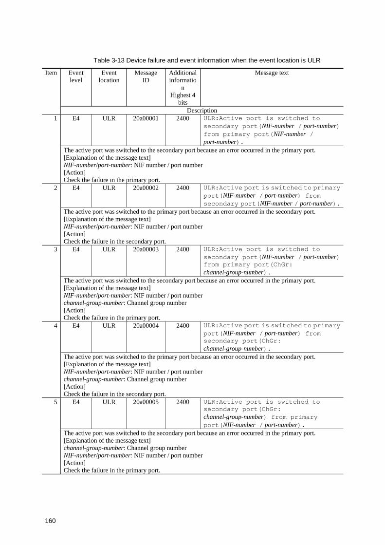
160
Table 3-13 Device failure and event information when the event location is ULR
Event level
Event location
Message ID
Additional informatio
n Highest 4
bits
Message text Item
Description E4 ULR 20a00001 2400 ULR:Active port is switched to
secondary port(NIF-number / port-number) from primary port(NIF-number / port-number).
1
The active port was switched to the secondary port because an error occurred in the primary port. [Explanation of the message text] NIF-number/port-number: NIF number / port number [Action] Check the failure in the primary port.
E4 ULR 20a00002 2400 ULR:Active port is switched to primary port(NIF-number / port-number) from secondary port(NIF-number / port-number).
2
The active port was switched to the primary port because an error occurred in the secondary port. [Explanation of the message text] NIF-number/port-number: NIF number / port number [Action] Check the failure in the secondary port.
E4 ULR 20a00003 2400 ULR:Active port is switched to secondary port(NIF-number / port-number) from primary port(ChGr: channel-group-number).
3
The active port was switched to the secondary port because an error occurred in the primary port. [Explanation of the message text] NIF-number/port-number: NIF number / port number channel-group-number: Channel group number [Action] Check the failure in the primary port.
E4 ULR 20a00004 2400 ULR:Active port is switched to primary port(NIF-number / port-number) from secondary port(ChGr: channel-group-number).
4
The active port was switched to the primary port because an error occurred in the secondary port. [Explanation of the message text] NIF-number/port-number: NIF number / port number channel-group-number: Channel group number [Action] Check the failure in the secondary port.
E4 ULR 20a00005 2400 ULR:Active port is switched to secondary port(ChGr: channel-group-number) from primary port(NIF-number / port-number).
5
The active port was switched to the secondary port because an error occurred in the primary port. [Explanation of the message text] channel-group-number: Channel group number NIF-number/port-number: NIF number / port number [Action] Check the failure in the primary port.
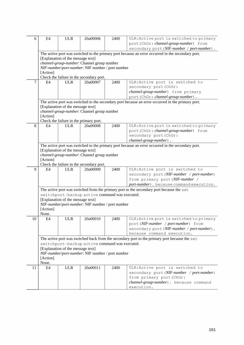
161
E4 ULR 20a00006 2400 ULR:Active port is switched to primary port(ChGr: channel-group-number) from secondary port(NIF-number / port-number).
6
The active port was switched to the primary port because an error occurred in the secondary port. [Explanation of the message text] channel-group-number: Channel group number NIF-number/port-number: NIF number / port number [Action] Check the failure in the secondary port.
E4 ULR 20a00007 2400 ULR:Active port is switched to secondary port(ChGr: channel-group-number) from primary port(ChGr: channel-group-number).
7
The active port was switched to the secondary port because an error occurred in the primary port. [Explanation of the message text] channel-group-number: Channel group number [Action] Check the failure in the primary port.
E4 ULR 20a00008 2400 ULR:Active port is switched to primary port(ChGr: channel-group-number) from secondary port(ChGr: channel-group-number).
8
The active port was switched to the primary port because an error occurred in the secondary port. [Explanation of the message text] channel-group-number: Channel group number [Action] Check the failure in the secondary port.
E4 ULR 20a00009 2400 ULR:Active port is switched to secondary port(NIF-number / port-number) from primary port(NIF-number / port-number), because command execution.
9
The active port was switched from the primary port to the secondary port because the set switchport-backup active command was executed. [Explanation of the message text] NIF-number/port-number: NIF number / port number [Action] None.
E4 ULR 20a00010 2400 ULR:Active port is switched to primary port(NIF-number / port-number) from secondary port(NIF-number / port-number), because command execution.
10
The active port was switched back from the secondary port to the primary port because the set switchport-backup active command was executed. [Explanation of the message text] NIF-number/port-number: NIF number / port number [Action] None.
11 E4 ULR 20a00011 2400 ULR:Active port is switched to secondary port(NIF-number / port-number) from primary port(ChGr: channel-group-number), because command execution.
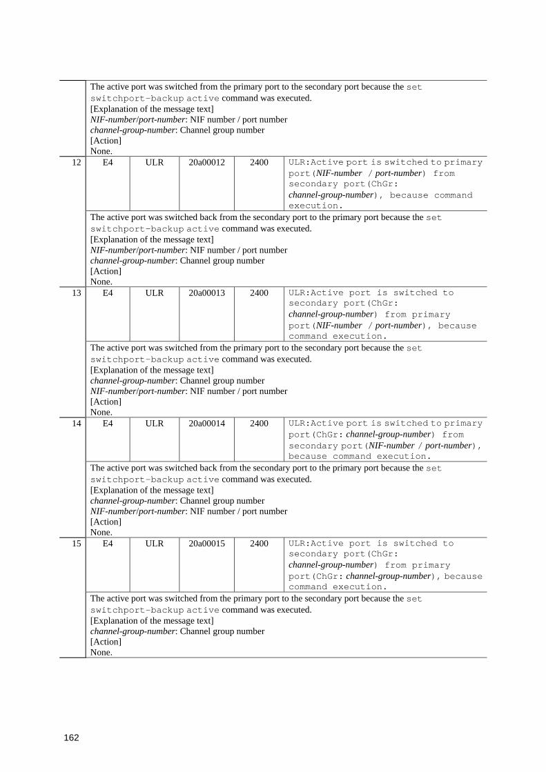
162
The active port was switched from the primary port to the secondary port because the set switchport-backup active command was executed. [Explanation of the message text] NIF-number/port-number: NIF number / port number channel-group-number: Channel group number [Action] None.
E4 ULR 20a00012 2400 ULR:Active port is switched to primary port(NIF-number / port-number) from secondary port(ChGr: channel-group-number), because command execution.
12
The active port was switched back from the secondary port to the primary port because the set switchport-backup active command was executed. [Explanation of the message text] NIF-number/port-number: NIF number / port number channel-group-number: Channel group number [Action] None.
E4 ULR 20a00013 2400 ULR:Active port is switched to secondary port(ChGr: channel-group-number) from primary port(NIF-number / port-number), because command execution.
13
The active port was switched from the primary port to the secondary port because the set switchport-backup active command was executed. [Explanation of the message text] channel-group-number: Channel group number NIF-number/port-number: NIF number / port number [Action] None.
E4 ULR 20a00014 2400 ULR:Active port is switched to primary port(ChGr: channel-group-number) from secondary port(NIF-number / port-number), because command execution.
14
The active port was switched back from the secondary port to the primary port because the set switchport-backup active command was executed. [Explanation of the message text] channel-group-number: Channel group number NIF-number/port-number: NIF number / port number [Action] None.
E4 ULR 20a00015 2400 ULR:Active port is switched to secondary port(ChGr: channel-group-number) from primary port(ChGr: channel-group-number), because command execution.
15
The active port was switched from the primary port to the secondary port because the set switchport-backup active command was executed. [Explanation of the message text] channel-group-number: Channel group number [Action] None.

163
E4 ULR 20a00016 2400 ULR:Active port is switched to primary ChGr(channel-group-number) from secondary ChGr(channel-group-number), because command execution.
16
The active port was switched back from the secondary port to the primary port because the set switchport-backup active command was executed. [Explanation of the message text] channel-group-number: Channel group number [Action] None.
E4 ULR 20a00017 2400 ULR:Primary port(NIF-number / port-number) became the active port.
17
The primary port has become the active port. [Explanation of the message text] NIF-number/port-number: NIF number / port number [Action] None.
E4 ULR 20a00018 2400 ULR:Primary port(ChGr: channel-group-number), became the active port.
18
The primary port has become the active port. [Explanation of the message text] channel-group-number: Channel group number [Action] None.
E4 ULR 20a00019 2400 ULR:Secondary port(NIF-number / port-number) became the active port.
19
The secondary port has become the active port. [Explanation of the message text] NIF-number/port-number: NIF number / port number [Action] None.
E4 ULR 20a00020 2400 ULR:Secondary port(ChGr: channel-group-number) became the active port.
20
The secondary port has become the active port. [Explanation of the message text] channel-group-number: Channel group number [Action] None.
E4 ULR 20a00021 2400 ULR:Both uplink redundant port(NIF-number / port-number) and port(NIF-number /port no.>) are down.
21
Both the primary port and the secondary port have gone down. [Explanation of the message text] NIF-number/port-number: NIF number / port number [Action] Make sure that no error occurred between the primary and secondary port.
22 E4 ULR 20a00022 2400 ULR:Both uplink redundant port(NIF-number / port-number) and port(ChGr: channel-group-number) are down.

164
Both the primary port and the secondary port have gone down. [Explanation of the message text] NIF-number/port-number: NIF number / port number channel-group-number: Channel group number [Action] Make sure that no error occurred between the primary and secondary port.
E4 ULR 20a00023 2400 ULR:Both uplink redundant port(ChGr: channel-group-number) and port(NIF-number / port-number) are down.
23
Both the primary port and the secondary port have gone down. [Explanation of the message text] channel-group-number: Channel group number NIF-number/port-number: NIF number / port number [Action] Make sure that no error occurred between the primary and secondary port.
E4 ULR 20a00024 2400 ULR:Both uplink redundant port(ChGr: channel-group-number) and port(ChGr: channel-group-number) are down.
24
Both the primary port and the secondary port have gone down. [Explanation of the message text] channel-group-number: Channel group number [Action] Make sure that no error occurred between the primary and secondary port.
E4 ULR 20a00025 2400 ULR:Active port is switched to primary port(NIF-number / port-number) from secondary port(NIF-number / port-number), because preemption execution.
25
The active port was switched from the secondary port to the primary port because automatic preemption was executed. [Explanation of the message text] NIF-number/port-number: NIF number / port number [Action] None.
E4 ULR 20a00026 2400 ULR:Active port is switched to primary port(NIF-number / port-number) from secondary port(ChGr: channel-group-number), because preemption execution.
26
The active port was switched from the secondary port to the primary port because automatic preemption was executed. [Explanation of the message text] NIF-number/port-number: NIF number / port number channel-group-number: Channel group number [Action] None.
E4 ULR 20a00027 2400 ULR:Active port is switched to primary port(ChGr: channel-group-number) from secondary port(NIF-number / port-number), because preemption execution.
27
The active port was switched from the secondary port to the primary port because automatic preemption was executed. [Explanation of the message text] channel-group-number: Channel group number NIF-number/port-number: NIF number / port number [Action] None.
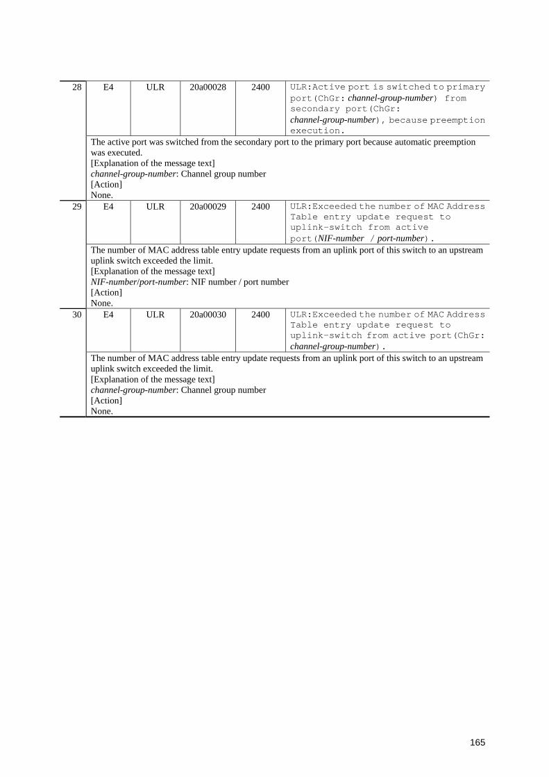
165
E4 ULR 20a00028 2400 ULR:Active port is switched to primary port(ChGr: channel-group-number) from secondary port(ChGr: channel-group-number), because preemption execution.
28
The active port was switched from the secondary port to the primary port because automatic preemption was executed. [Explanation of the message text] channel-group-number: Channel group number [Action] None.
E4 ULR 20a00029 2400 ULR:Exceeded the number of MAC Address Table entry update request to uplink-switch from active port(NIF-number / port-number).
29
The number of MAC address table entry update requests from an uplink port of this switch to an upstream uplink switch exceeded the limit. [Explanation of the message text] NIF-number/port-number: NIF number / port number [Action] None.
E4 ULR 20a00030 2400 ULR:Exceeded the number of MAC Address Table entry update request to uplink-switch from active port(ChGr: channel-group-number).
30
The number of MAC address table entry update requests from an uplink port of this switch to an upstream uplink switch exceeded the limit. [Explanation of the message text] channel-group-number: Channel group number [Action] None.

166
3.6 Option Structure
3.6.1 Event location = PS
The following table describes device failure and event information when the event location is
PS.
Table 3-14 Device failure and event information when the event location is PS
Event level
Event location
Message ID
Additional informatio
n Highest 4
bits
Message text Item
Description E3 PS 00000003 2200 Failed in accumulated running time
access to PS. 1
Access to the total operating time for a PS unit failed. PS displays the PS unit (either PS1 or PS2) for which access to the total operating time failed. [Explanation of the message text] PS: PS1 or PS2 [Action] This event does not affect communication and usual operation. However, you cannot use the total operating time management function. If you want to use the function, change the PS unit.
E8 PS 00000001 2200 PS is power off. 2 The displayed power unit is turned off. PS displays the power unit (either PS or EPU) that is turned off. [Explanation of the message text] PS: PS or EPU [Action] 1. Check the power switch, and turn it on. 2. Check the power cable connection and the power source, and then connect them properly. 3. Check the implementation status of the external reserve power.
E8 PS 00000002 2200 PS is power off. 3 The displayed power unit is either turned off or is not implemented. PS displays the power unit (either PS1 or PS2) that is turned off or is not implemented. [Explanation of the message text] PS: PS1 or PS2 [Action] 1. Check the power switch, and turn it on. 2. Check the power cable connection and the power source, and then connect them properly. 3. Check the implementation status of the power unit.
Visually check the implementation status or check it by using the show system command. 4. If the power unit has failed, replace it.
E8 PS 00000102 2200 Power unit isn't redundantly mounted.4 The power unit is not in a redundant configuration. [Explanation of the message text] None. [Action] Check the implementation status of the power unit. If the power unit is not implemented in a redundant configuration, set no power redundancy-mode by the configuration command.
5 R8 PS 00000001 2200 PS is normal.

167
The displayed power unit is in a normal state. PS displays the power unit (either PS or EPU) that is in a normal state. This message appears when the following conditions are met: 1. When the power unit state changes from an anomalous state to a normal state, or from an
unimplemented state to a normal state, the power unit in the normal state is displayed. 2. When an EPU is removed for a power unit that is in a redundant configuration, PS in a normal state
is displayed. [Explanation of the message text] PS: PS or EPU [Action] None.
R8 PS 00000002 2200 PS is normal. 6 The displayed power unit is in a normal state. PS displays a power unit (either PS1 or PS2) that is in a normal state. 1. When the power unit state changes from an anomalous state to a normal state, or from an
unimplemented state to a normal state, the power unit in the normal state is displayed. 2. When either one of the power units in a redundant configuration is removed, the power unit in the
normal state is displayed. [Explanation of the message text] PS: PS1 or PS2 [Action] None.
R8 PS 00000102 2200 Power unit is mounted redundantly or mode changed.
7
The power unit has been implemented in a redundant configuration, or the operation mode has changed. [Explanation of the message text] None. [Action] None.
3.6.2 Event location = EQUIPMENT
The following table describes device failure and event information when the event location is
EQUIPMENT.
Table 3-15: Device failure and event information when the event location is EQUIPMENT
Event level
Event location
Message ID
Additional informatio
n Highest 4
bits
Message text Item
Description E3 EQUIPM
ENT 00000003 2101 Failed in accumulated running time
access to main. 1
Access to the total operating time for the switch failed. [Explanation of the message text] None. [Action] This event does not affect communication and usual operation. However, you cannot use the total operating time management function. If you want to use this function, replace the device.
2 E3 EQUIPMENT
25040b01 2101 Layer-2 hardware table entry can't be registered. Change to recommended l2-table mode mode.

168
An entry could not be registered in the layer-2 hardware table. Change the search method for the layer-2 hardware table to mode. [Explanation of the message text] mode: Search method of the layer-2 hardware table after the change [Action] None.
E3 EQUIPMENT
25040b02 2101 Layer-2 hardware table entry can't be registered. The recommended l2-table mode is mode.
3
An entry could not be registered in the layer-2 hardware table. The search method for the most optimal layer-2 hardware table is mode. [Explanation of the message text] mode: Search method of the most optimal layer-2 hardware table [Action] When using the search method displayed in this message, change the configuration command system l2-table mode, and execute the restart vlan command.
E3 EQUIPMENT
25040b03 2101 The recommended l2-table mode can't be selected.
4
The search method for the most optimal layer-2 hardware table could not be selected. [Explanation of the message text] None. [Action] Review the system configuration.
E3 EQUIPMENT
25040c01 2101 Corrected memory soft errors. 5
The system has recovered from a memory software error. Some frames may were discarded because of the software error. [Explanation of the message text] None. [Action] None. This indicates that the memory data bits inside a switch processor might have been abruptly altered (for example by cosmic rays from a solar flare) and a software error is issued temporarily. This is not a hardware failure.
E7 EQUIPMENT
00020102 2101 Hardware exceeded tolerance level of low temperature(0 degree). Check room temperature.
6
The hardware temperature went below the minimum value of the permissible temperature range (0 degrees Celsius). [Explanation of the message text] None. [Action] 1. Check and, if necessary, improve the environment such as the room temperature around the switches.2. Check and, if necessary, replace the fan.
E7 EQUIPMENT
00020103 2101 Hardware exceeded tolerance level of high temperature (40 degree). Check that room temperature and the fan is operating normally.
7
The hardware temperature rose above the maximum value of the permissible temperature range (40 degrees Celsius). [Explanation of the message text] None. [Action] 1. Check and, if necessary, improve the environment such as ventilation and heat sources around the
switches. 2. Check and, if necessary, replace the fan.

169
E8 EQUIPMENT
00000001 2102 FAN stopped. 8
A failure was detected at the displayed fan. You can identify the stopped fan by the additional information. Additional information = 2102:ABCD******** "*" represents an indefinite value. It can be ignored. A, B, C, and D correspond to the fan numbers. A=FAN4 0=Normal, 1=Stopped B=FAN3 0=Normal, 1=Stopped C=FAN2 0=Normal, 1=Stopped D=FAN1 0=Normal, 1=Stopped [Explanation of the message text] None. [Action] Replace the device.
E8 EQUIPMENT
25040201 2101 Hardware restarted because of its failure.
9
The switch was restarted because a hardware failure occurred at the switch. [Explanation of the message text] None. [Action] Check subsequent fault recovery log entries or fault recovery failure log entries. If the recovery was successful, operations can resume. If the recovery failed, replace the device.
E8 EQUIPMENT
25040400 2101 Hardware restarted, but not recovered.10
The device restarted, but it has not recovered from a hardware failure. [Explanation of the message text] None. [Action] Replace the device.
E9 EQUIPMENT
00020105 2101 Hardware is becoming high temperature which give damage to this system. (tempdegree).
11
The hardware temperature has reached a temperature (50 degrees Celsius or higher) that is likely to critically damage device operation. [Explanation of the message text] temp: Detected temperature [Action] 1. Check and improve the environment such as ventilation and heat sources around the switches. 2. Check and, if necessary, replace the fan.
R7 EQUIPMENT
00020102 2101 The temperature of hardware returnedto normal level (3 degree).
12
The hardware temperature returned to normal (3 degrees Celsius). [Explanation of the message text] None. [Action] None.
R7 EQUIPMENT
00020103 2101 The temperature of hardware returned to normal level (37 degree).
13
The hardware temperature returned to normal (37 degrees Celsius). [Explanation of the message text] None. [Action] None.
14 R8 EQUIPMENT
00000001 2102 FAN is normal.
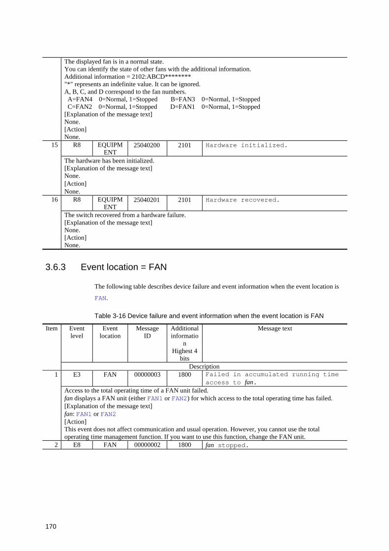
170
The displayed fan is in a normal state. You can identify the state of other fans with the additional information. Additional information = 2102:ABCD******** "*" represents an indefinite value. It can be ignored. A, B, C, and D correspond to the fan numbers. A=FAN4 0=Normal, 1=Stopped B=FAN3 0=Normal, 1=Stopped C=FAN2 0=Normal, 1=Stopped D=FAN1 0=Normal, 1=Stopped [Explanation of the message text] None. [Action] None.
R8 EQUIPMENT
25040200 2101 Hardware initialized. 15
The hardware has been initialized. [Explanation of the message text] None. [Action] None.
R8 EQUIPMENT
25040201 2101 Hardware recovered. 16
The switch recovered from a hardware failure. [Explanation of the message text] None. [Action] None.
3.6.3 Event location = FAN
The following table describes device failure and event information when the event location is
FAN.
Table 3-16 Device failure and event information when the event location is FAN
Event level
Event location
Message ID
Additional informatio
n Highest 4
bits
Message text Item
Description E3 FAN 00000003 1800 Failed in accumulated running time
access to fan. 1
Access to the total operating time of a FAN unit failed. fan displays a FAN unit (either FAN1 or FAN2) for which access to the total operating time has failed. [Explanation of the message text] fan: FAN1 or FAN2 [Action] This event does not affect communication and usual operation. However, you cannot use the total operating time management function. If you want to use this function, change the FAN unit.
2 E8 FAN 00000002 1800 fan stopped.
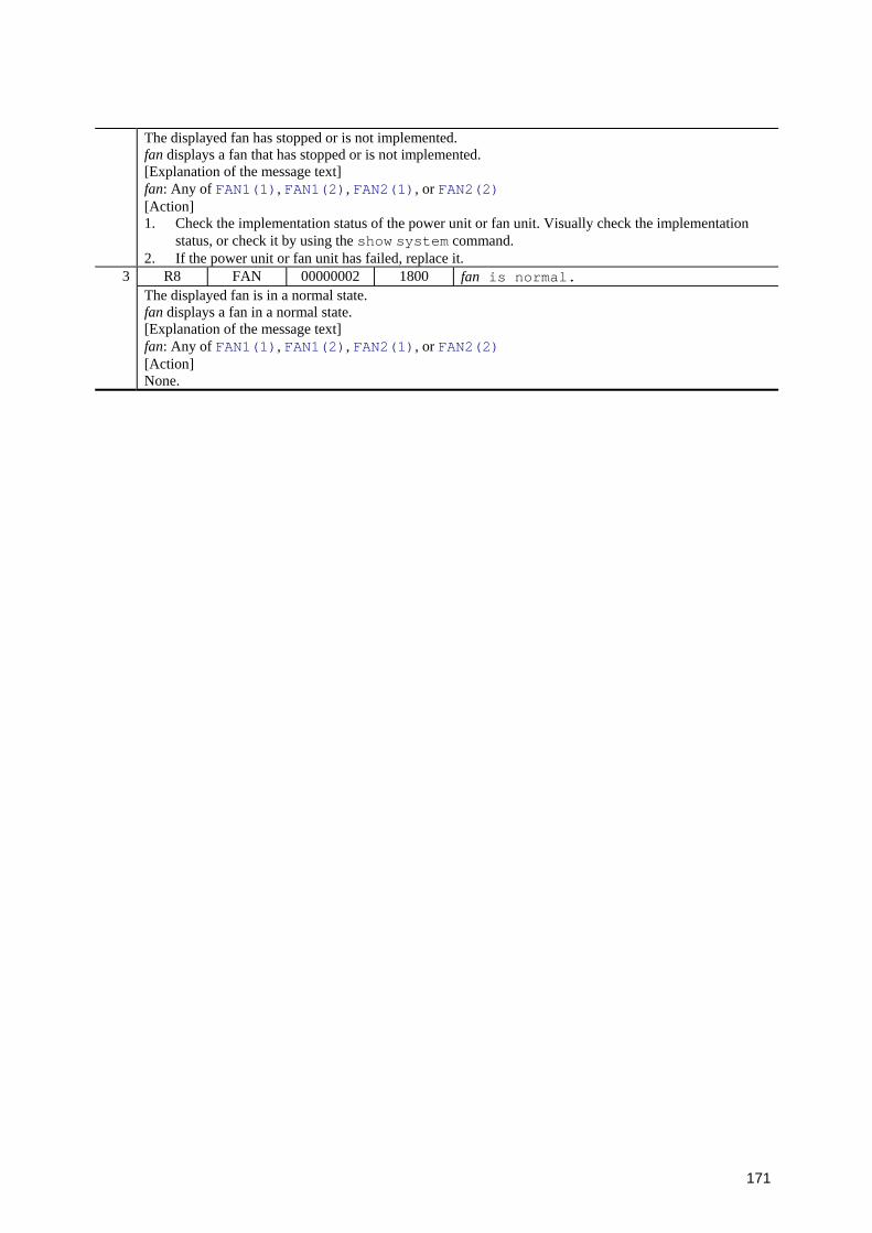
171
The displayed fan has stopped or is not implemented. fan displays a fan that has stopped or is not implemented. [Explanation of the message text] fan: Any of FAN1(1), FAN1(2), FAN2(1), or FAN2(2) [Action] 1. Check the implementation status of the power unit or fan unit. Visually check the implementation
status, or check it by using the show system command. 2. If the power unit or fan unit has failed, replace it.
R8 FAN 00000002 1800 fan is normal. 3 The displayed fan is in a normal state. fan displays a fan in a normal state. [Explanation of the message text] fan: Any of FAN1(1), FAN1(2), FAN2(1), or FAN2(2) [Action] None.