ax 144 cb radio owners manual - angelfire
TRANSCRIPT
. , r'-=::::::::
uniden
"
AX 144 CB RADIOOWNERS MANUAL
-- n--------.
Downloaded from www.Manualslib.com manuals search engine
L
-- --- -.
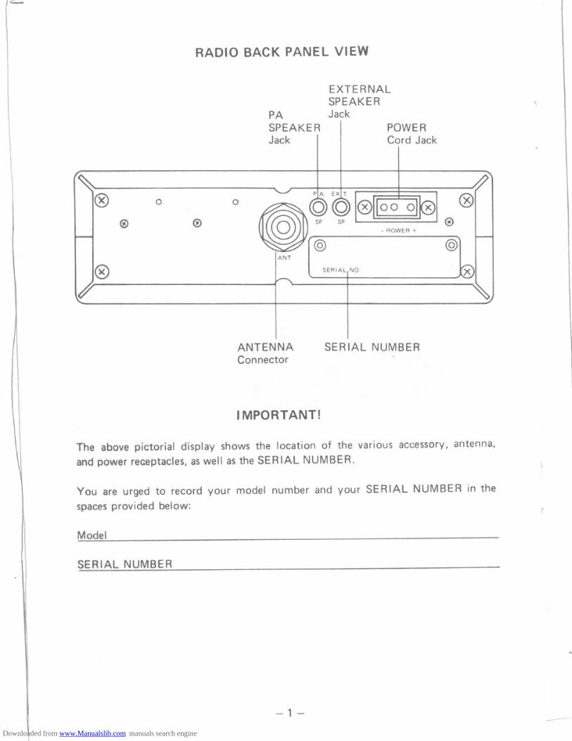
RADIO BACK PANEL VIEW
EXTERNALSPEAKER
PA JackSPEAKERJack
POWERCord Jack
ANT
SERIAL,NO
ANTENNAConnector
SERIAL NUMBER
I MPORT ANT!
The above pictorial display shows the location of the various accessory, antenna,
and power receptacles, as well as the SERIAL NUMBER.
You are urged to record your model number and your SERIAL NUMBER in thespaces provided below:
Model
SERIAL NUMBER
-1-
-. - --------
}--
@ 0 0
@ @
@
Downloaded from www.Manualslib.com manuals search engine
~.n
GENERAL
Channels
Frequency RangeFrequency ControlFrequency ToleranceFrequency StabilityOperating Temperature RangeMicrophone
Input Voltage
Current Drain
Cabinet Dimensions
WeightAntenna ConnectorSemiconductors
Meter
Indicators
TRANSMITTER
Power OutputModulationIntermodulation Distortion
SSB Carrier SuppressionUnwanted Sideband
Frequency ResponseOutput ImpedanceSSB Filter
Output Indicators
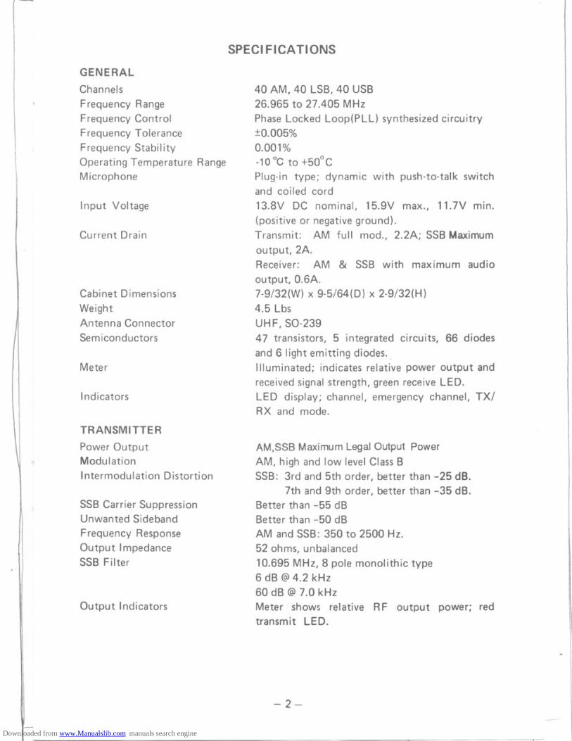
SPECIFICATIONS
40 AM, 40 LSB, 40 USB26.965 to 27.405 MHz
Phase Locked Loop(PLL) synthesized circuitry:to.005%0.001 %-10°C to +50°CPlug-in type; dynamic with push-to-talk switchand coiled cord
13.8V DC nominal, 15.9V max., 11.7V min.(positive or negative ground).Transmit: AM full mod., 2.2A; SSB Maximum
output,2A.Receiver: AM & SSB with maximum audio
output, 0.6A.7-9/32(W) x 9-5/64(0) x 2-9/32(H)4.5 Lbs
UHF, SO-23947 transistors, 5 integrated circuits, 66 diodes
and 6 light emitting diodes..Illuminated; indicates relative power output and
received signal strength, green receive LED.LED display; channel, emergency channel, TX/RX and mode.
AM,SSB Maximum Legal Output PowerAM, high and Iow level Class BSSB: 3rd and 5th order, better than -25 dB.
7th and 9th order, better than -35 dB.Better than -55 dBBetter than -50 dBAM and SSB: 350 to 2500 Hz.
52 ohms, unbalanced10.695 MHz, 8 pole monolithic type6 dB @4.2 kHz60 dB @ 7.0 kHz
Meter shows relative RF output power; redtransmit LED.
-2-
rj ,------
Downloaded from www.Manualslib.com manuals search engine

RECEIVER
Sensitivity
SelectivityCross Modulation
Image Rejectiont.F. FrequencyAM and SSB RF Gain ControlAutomatic Gain Control
SquelchNoise Blanker
Clarifier RangeAudio Output PowerFrequency ResponseDistortion
Built-in SpeakerExternal Speaker (Not Supplied)
PA SYSTEM
Power OutputExternal Speaker for PA
SSB: Better than ,25 p V for 10 dB(S+N)/N at greater than 1f2watt of audiooutput
AM: Better than .5 pV for 10 dB
(S+N)/N at greater than 1f2watt of audiooutput
SSB and AM: 6 dB @ 4.2 kHz, 60 dB @ 7.0 kHzMore than 50 dBMore than 75 dBAM and SSB: 10.695 MHz
Adjustable for optimum signal reception.(AGC): Less than 10 dB change in audio outputfor inputs from 10 to 500,000 microvolts.Adjustable; threshold less than .5 pV.RF type, effective on AM and SSB.::\:1.0kHz3 watts into 8 ohms350 to 2500 Hz
Less than 10% at 3 watts output.16 ohms, round8 ohms; disables internal speaker when con-nected.
3 watts into external speaker.8 ohms (not supplied)
-3-
- Ij ,---------
Downloaded from www.Manualslib.com manuals search engine
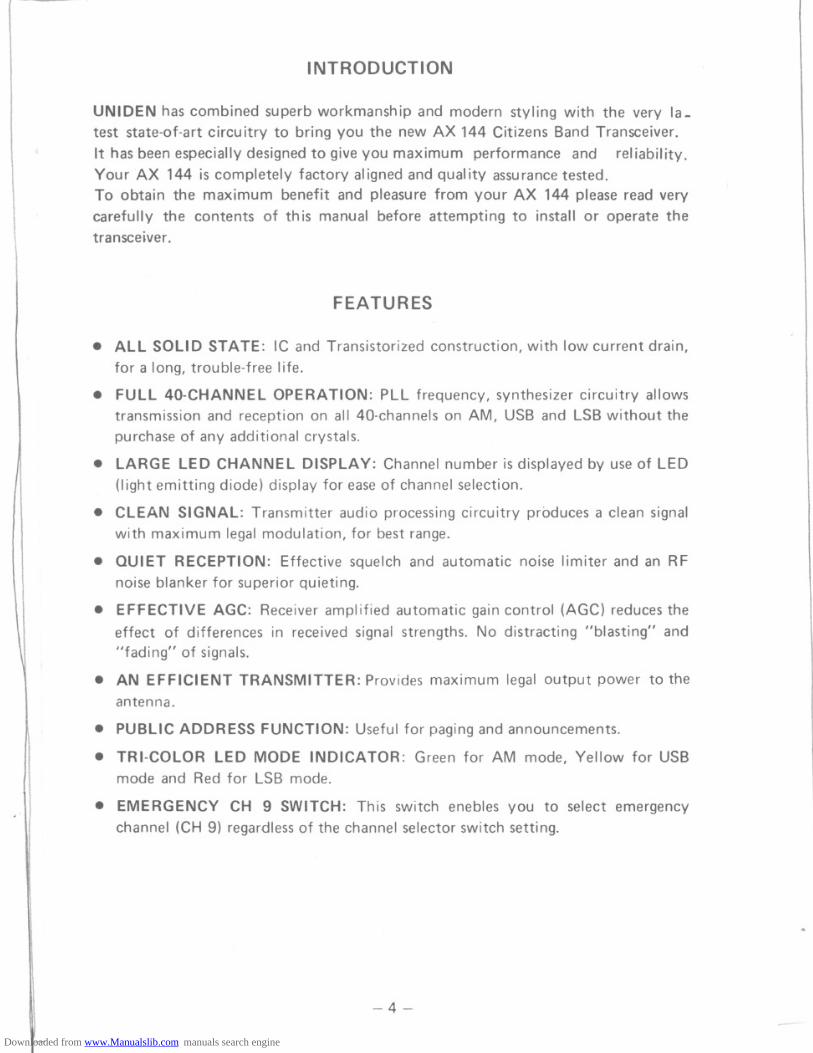
INTRODUCTION
UNIDEN has combined superb workmanship and modern styling with the very la-test state-of-art circuitry to bring you the new AX 144 Citizens Band Transceiver.
It has been especially designed to give you maximum performance and reliability.YourAX 144 is completely factory aligned and quality assurance tested.To obtain the maximum benefit and pleasure from your AX 144 please read verycarefully the contents of this manual before attempting to install or operate thetransce~ver .
FEATURES
. ALL SOLID STATE: IC and Transistorized construction, with Iow current drain,for a long, trouble-free life.
. FULL 40-CHANNEL OPERATION: PLL frequency, synthesizer circuitry allowstransmission and reception on all 40-channels on AM, USB and LSBwithout thepurchase of any additional crystals.
. LARGE LED CHANNELDISPLAY: Channel number is displayed by use of LED(light emitting diode) display for ease of channel selection.
. CLEAN SIGNAL: Transmitter audio processing circuitry produces a clean signalwith maximum legalmodulation, for best range.
. QUIET RECEPTION: Effective squelch and automatic noise limiter and an RFnoise blanker for superior quieting.
. EFFECTIVE AGC: Receiver amplified automatic gain control (AGC) reduces theeffect of differences in received signal strengths. No distracting "blasting" and"fading" of signals.
. AN EFFICIENT TRANSMITTER:Provides maximum legal output power to theantenna.
. PUBLICADDRESSFUNCTION: Usefulfor pagingand announcements.
. TRI-COLOR LED MODE INDICATOR: Green for AM mode, Yellow for USBmode and Red for LSB mode.
. EMERGENCY CH 9 SWITCH: This switch enebles you to select emergencychannel (CH 9) regardlessof the channel selector switch setting.
-4-
rt
-- --- -
Downloaded from www.Manualslib.com manuals search engine
~, ==
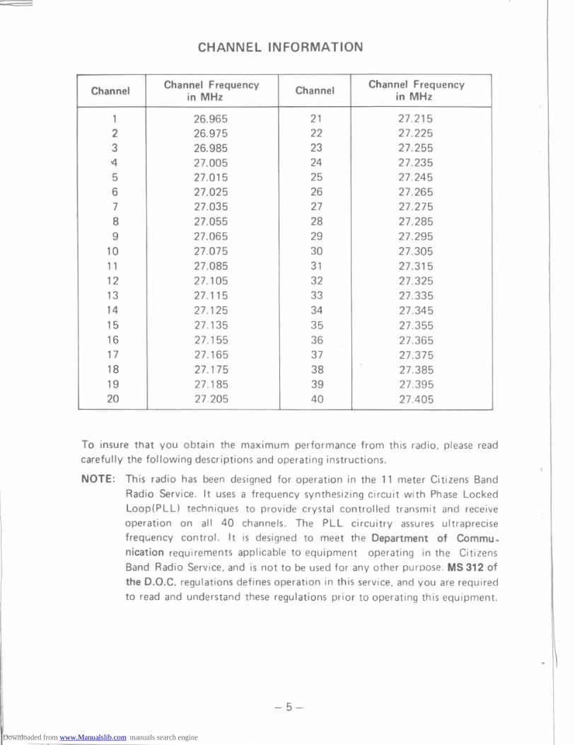
CHANNEL INFORMATION
To insure that you obtain the maximum performance from this radio, please readcarefully the following descriptions and operating instructions.
NOTE: This radio has been designed for operation in the 11 meter Citizens BandRadio Service. It uses a frequency synthesizing circuit with Phase LockedLoop(PLL) techniques to provide crystal controlled transmit and receiveoperation on all 40 channels. The PLL circuitry assures ultraprecisefrequency control. It is designed to meet the Department of Commu~nication requirements applicable to equipment operating in the CitizensBand Radio Service, and is not to be used for any other purpose. MS 312 ofthe D.O.C. regulations defines operation in this service, and you are requiredto read and understand these regulations prior to operating this equipment.
-5-
~ Ij ,--------
Channel Channel Frequency Channel Channel Frequencyin MHz in MHz
1 26.965 21 27.2152 26.975 22 27.2253 26.985 23 27.255-4 27.005 24 27.2355 27.015 25 27.2456 27.025 26 27.2657 27.035 27 27.2758 27.055 28 27.2859 27.065 29 27.295
10 27.075 30 27.30511 27.085 31 27.31512 27.105 32 27.32513 27.115 33 27.33514 27.125 34 27.34515 27.135 35 27.35516 27. 155 36 27.36517 27.165 37 27.37518 27.175 38 27.38519 27.185 39 27.39520 27.205 40 27.405
Downloaded from www.Manualslib.com manuals search engine

INSTAllATION
Location
Plan the location of the transceiver and microphone bracket before starting theinstallation. Select a location that is convenient for operation and does not interferewith the driver or passenger in the vehicle. In automobiles, the transceiver is usuallymounted to the dash panel with the microphone bracket beside it.
Mounting and Connection
This radio is supplied with a universal mounting bracket. The transceiver is held inthe bracket by the two thumb screws supplied, permftting adjustment to the mostconvenient angle. The bracket must be mounted with the machine screws supplied.The mounting surface must be mechanically strong. Proceed as follows to mount thetransceiver:
1. After you have determined the most convenient location in your vehicle, hold theradio with mounting bracket in the exact location desired. If nothing interfereswith mounting it in the desired position, remove the mounting bracket bolts.Before drilling the holes, make sure nothing will interfere with the installation ofthe mounting bolts.
2. Connect the antenna cable plug to the standard receptacle on the rear panel. MostCB antennas are terminated with a type PL-259 plug which mates with thereceptacle on the rear panel.
3. Connect the DC power input wire with the fuse (red) to +12V DC. This wireextends from a plug which connects to the rear panel. In automobile installations,+12V DC is usually obtained from the accessory contact on the ignition switch.
-6-
rj ,------
Downloaded from www.Manualslib.com manuals search engine
~= .-'--'
This prevents the set being left on accidentally when the driver leaves the car andalso permits operating the radio without the engine running. You can locate theaccessory contact on most ignition switches by tracing the power wire from theAM broadcast receiver in the car.
Note: See ground connection under GENERAL INFORMATION for more detail.
4. Connect the black wire to ground. This is usually the chassis of the car. Any con-venient location with good electrical contact may be used. (remove paint).
5. Mount the microphone hanger on the side of the unit or near the unit, using twoscrews supplied. When mounting in an automobile, place the hanger on the dashso the microphone is easily accessible.
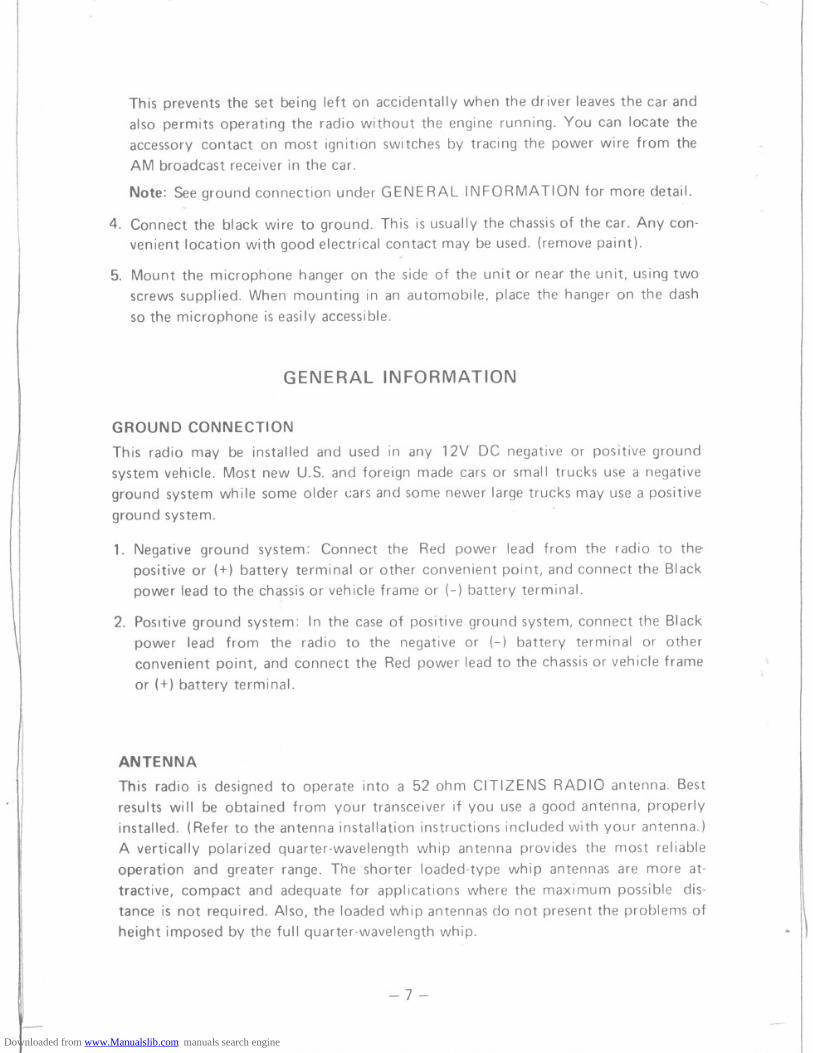
GENERAL INFORMATION
GROUND CONNECTION
This radio may be installed and used in any 12V DC negative or positive groundsystem vehicle. Most new U.S. and foreign made cars or small trucks use a negativeground system while some older cars and some newer large trucks may use a positiveground system.
1. Negative ground system: Connect the Red power lead from the radio to the-positive or (+) battery terminal or other convenient point, and connect the Blackpower lead to the chassis or vehicle frame or (-) battery terminal.
2. Positive ground system: In the case of positive ground system, connect the Blackpower lead from the radio to the negative or (-) battery terminal or otherconvenient point, and connect the Red power lead to the chassis or vehicle frameor (+) battery terminal.
ANTENNA
This radio is designed to operate into a 52 ohm CITIZENS RADIO antenna. Bestresults will be obtained from your transceiver if you use a good antenna, properlyinstalled. (Refer to the antenna installation instructions included with your antenna.)
A vertically polarized quarter-wavelength whip antenna provides the most reliableoperation and greater range. The shorter loaded-type whip antennas are more at-tractive, compact and adequate for applications where the maximum possible dis-tance is not required. Also, the loaded whip antennas do not present the problems ofheight imposed by the full quarter-wavelength whip.
-7-
-.---
-- r-----Downloaded from www.Manualslib.com manuals search engine

Mobile whip antennas utilize the metal body of the vehicle as a ground plane. When
mounted on a corner of the vehicle, they are slightly directional, in the direction ofthe body of the vehicle. For all practical purposes, however, the radiation pattern is
non-directional. A slight directional characteristic wi 11be observed only at extreme
distances. A standard antenna connector (Type SO-239) is provided on thetransceiver for easy connection to a standard PL-259 cable termination.
When installed in a boat, the transceiver will perform most efficiently whenantenna used has been specifically designed for marine applications.
Before installing the transceiver in a boat, consult your dealer for information
regarding an adequate grounding system and prevention of electrolysis between fitt-ings in the hull and water.
BASE STATION OPERATION
To operate the transceiver from your home or office, using regular house current as
the power source, you will require a separate power supply capable of supplying 2.5amps at a 13.8V DC output with a nominal input voltage of 120 volts AC, 50/60Hz.
Simply connect the red (+) and black (-) leads of the transceiver to the correspond-ing DC terminals of the power supply.
NOTE: Do not attempt to operate th is transceiver by connectin.g directly to 117VAC. When AC power supply is used with the transceiver for base station
operation any Citizens Band beam, dipole, ground plane or vertical antenna
may be used. A ground plane vertical antenna wi II provide the most uniformhorizontal coverage.
REMOTE SPEAKER
The external speaker jack (EXT. SPKR) on the rear panel is used for remote receiver
monitoring. The external speaker should have 8 ohms impedance. When the externalspeaker is plugged in, the internal speaker is disconnected.
PUBLIC ADDRESS
An external 8 ohm 4-watt speaker must be connected to the (PA SPKR) jack locatedon the rear panel when the transceiver is used as a public address system. The speakershould be directed away from the microphone to prevent acoustic feedback. Physicalseparation or isolation of the microphone and speaker is important when operatingthe PA at high output levels.
-8-
--- ----
Downloaded from www.Manualslib.com manuals search engine
~
' -,
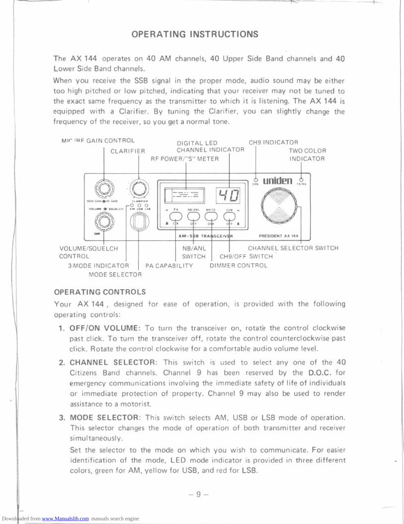
OPERATING INSTRUCTIONS
The AX 144 operates on 40 AM channels, 40 Upper Side Band channels and 40Lower Side Band channels.
When you receive the SSB signal in the proper mode, audio sound may be eithertoo high pitched or Iow pitched, indicating that your receiver may not be tuned tothe exact same frequency as the transmitter to which it is listening. The AX 144 isequipped with a Clarifier. By tuning the Clarifier, you can slightly change thefrequency of the receiver, so you get a normal tone.
Mlr IRF GAIN CONTROL DIGITAL LED CH9 INDICATOR
I CLARIFIER CHANNEL INDICATORI
T,
WO COLOR
. I RF POWER/"S" METER I INDICATOR
uniden
AM-St;B TRAI\ISCEIVI!R PRESIDENT AX 144
VOLUME/SQUELCH
I
I
I
NB/ANL
I
I CHANNE~ SELECTOR SWITCHCONTROL SWITCH CH9/0FF SWITCH
3-MODE INDICATOR PA CAPABILITY DIMMER CONTROLMODE SELECTOR
OPERATING CONTROLS
Your AX 144, designed for ease of operation, is provided with the followingoperating controls:
1. OFF/ON VOLUME: To turn the transceiver on, rotate the control clockwise
past click. To turn the transceiver off, rotate the control counterclockwise pastclick. Rotate the control clockwise for a comfortable audio volume level.
2. CHANNEL SELECTOR: This switch is used to select anyone of the 40Citizens Band channels. Channel 9 has been reserved by the D.O.C. foremergency communications involving the immediate safety of life of individualsor immediate protection of property. Channel 9 may also be used to renderassistance to a motorist.
3. MODE SELECTOR: This switch selects AM, USB or LSB mode of operation.This selector changes the mode of operation of both transmitter and receiversimultaneously.
Set the selector to the mode on which you wish to communicate. For easieridentification of the mode, LED mode indicator is provided in three differentcolors, green for AM, yellow for USB, and red for LSB.
-9-
- - ~--------Downloaded from www.Manualslib.com manuals search engine

,~~
T
4. SQUELCH: The squelch control is normally set to a position which justeliminates undesired background noise with no signal present. With the audiovolume adjusted to a satisfactory level, rotate the Squelch control clockwise tothe point where the sound from the speaker is cut off. In this position, there will
be no sound from the speaker until a signal is received. In order to hear weaksignals, it may be necessary to rotate the Squelch control counterclockwise,allowing some background noise to be heard.
5. CLARI FIER: The clarifier is normally set to the center position. This featurehas several uses and can greatly enhance receiver operation. If a receive signalis slightly off frequency, this control can be operated to optimize the receivesignal. This control is primarily intended to tune in SSB signals, but, it may bealso used to optimize the AM signal.
6. MIKEGAIN: This control is used to adjust, as required, microphone inputsensitivity for optimum amount of modulation in transmit UN IDEN's citizen'sband transceivers have been designed to permit the user to attain levels ofmodulation up to 100% depending on the setting of the microphone gaincontrol, using the microphone provided with the unit. UNIDEN's automaticcompression and peak limiting circuits assure maximum modualtion with mini-mum distortion.
7. DIMMER SWITCH: This switch is used to adjust the brightness of the LEDchannel display and the meter. 0 IM position reduces brightness.
8. CH9 SWITCH: This switch is for use when emergency communication is neededon the emergency channel CH9. Pressing the CH9 switch activates CH9regardless of the position of the channel selector switch. When CH9 switch ispressed, the channel display is blanked and the CH9 indicator is activated.
9. PA-CB SWITCH: This control engages the PA function. The PA function shouldnot be used unless an external speaker is connected. In the CB position, the PAfunction is disabled and the radio will transmit and receive on the selectedchannel.
10. NB/ANL SWITCH: When the switch is placed in the NB/ANL position, both ofRF Noise Blanker and Automatic Noise Limiter circuits are activated. The
NB is very effective for repetitive impulse noise such as ignition noise. TheANL reduces annoying hash-type noises.
11. RF GAIN: This control is used primarily to optimize reception in strong signalareas. Gain is reduced by counterclockwise rotation of the control.
.. r\
- 10-
1+
-
Downloaded from www.Manualslib.com manuals search engine
<:::::::e: - -
INDICATOR FUNCTION
1. S/RF METER: This meter displays relative transmitter RF output power whentransmitting, and input signal strength when receiving. The meter is illuminatedwhen power is on, the illumination can be adjusted by the DIMMER switch for
optimum brightness.
TX/RX INDICATOR: The TX/RX light in the upper right corner of the frontpanel lights in red color when the microphone button is pressed and transmitteris in operation. It lights in green color when the microphone button is releasedand the receiver is in operation.
2.
PRESSTO TALK MICROPHONE
The receiver and transmitter are controlled by the press-to-talk switch on themicrophone. Press the switch and the transmitter is activated. Release the switchto receive. When transmitting, hold the microphone about three inches from yourmouth and speak at a normal voice level.
RECEIVE OPERATING PROCEDURE
1. Place the CB-PA switch in CB position.
2. Turn the set on by turning the VOLUME CONTROL clockwis~, past click.
NOTE: Microphone must be plugged in for receiver to operate.
3.
4.
5.
Set the VOLUME CONTROL to a comfortable level.
Set the Mode Selector Switch to the desired mode.
Listen to the background noise from the speaker. Turn the SQUELCHCONTROL slowly clockwi-se, until the noise just disappears. The Squelch is nowproperly adjusted. The receiver will remain quiet until a signal is received. Donot advance th€ control too far, or some of the weaker signals will not be heard.
Set the Channel Selector to the desired channel.
Adjust the CLARIFIER to clearly receive SSB or AM signals.
6.
7.
TRANSMIT OPERATING PROCEDURE
1. Select the desired channel of transmission.
2. If the channel is clear, depress the push-to-talk switch on the microphone andspeak in a normal voice.
- 11 -
'f"::; Ij ,--------
Downloaded from www.Manualslib.com manuals search engine
WARNING
Oper:ation of this equipment requires a valid station license issued by the Depart-ment of Communication Do not transmit with your equipment until you havea license.
- 12-
1r-t
Downloaded from www.Manualslib.com manuals search engine

<::::;--- n .- -~
MAINTENANCE AND ADJUSTMENT
This transceiver is especially designed for the environment encountered in mobileinstallations. The use of all solid state circuitry and its light weight result in high
reliability. Should failure occur, however, replace parts only with identical parts. Donot substitute.
-13 -
~F::
- ------Downloaded from www.Manualslib.com manuals search engine

- 14-
- I1 ,-----
Downloaded from www.Manualslib.com manuals search engine
.~
V!n; !~
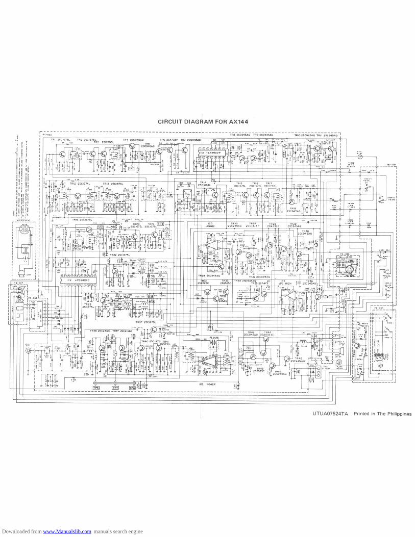
CIRCUIT DIAGJAM FOR AX144
r------------------------------------------------I PC-833
I I TRI 2SCI675LIIIIIIJIIIIIIIIIIIIIIIII
.'0'
PI-ooe,IIIIIIIII
0404-' I.O/ANC I
IIIIIIIIIIIJ~IIIIIIIIIIIIIIIIIIIIII
UTUAO7524T A Printed in The Philippines
Downloaded from www.Manualslib.com manuals search engine
UTUAO1524TC
x:
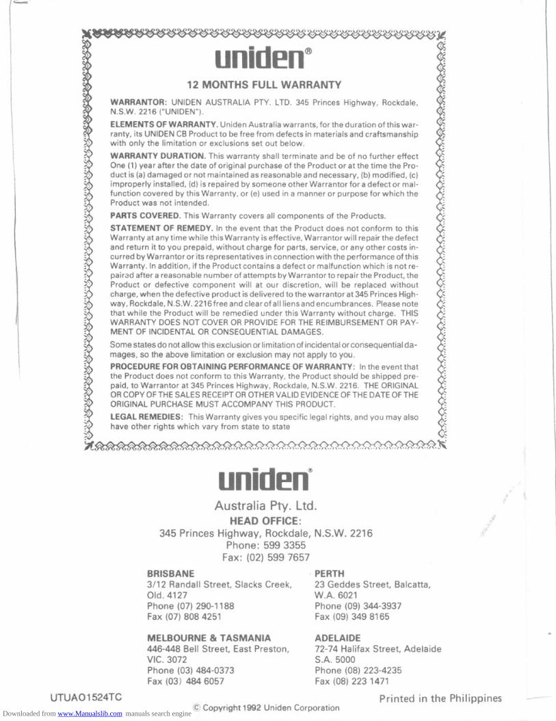
uniden@12 MONTHS FULL WARRANTY
WARRANTOR: UNIDEN AUSTRALIA PTY. LTD. 345 Princes Highway, Rockdale,N.S.W. 2216 ("UNIDEN").
ELEMENTS OF WARRANTY. Uniden Australia warrants, for the duration of this war-
ranty, its UNIDEN CB Product to be free from defects in materials and craftsmanshipwith only the limitation or exclusions set out below.
WARRANTY DURATION. This warranty shall terminate and be of no further effectOne (1) year after the date of original purchase of the Product or at the time the Pro-duct is (a) damaged or not maintained as reasonable and necessary, (b) modified, (c)improperly installed, (d) is repaired by someone other Warrantor for a defect or mal-function covered by this Warranty, or (e) used in a manner or- purpose for which theProduct was not intended.
PARTS COVERED. This Warranty covers all components of the Products.
STATEMENT OF REMEDY. 'n the event that the Product does not conform to this
Warranty at any time while this Warranty is effective, Warrantor will repair the defectand return it to you prepaid, without charge for parts, service, or any other costs in-curred by Warrantor or its representatives in connection with the performance of thisWarranty. In addition, if the Product contains a defect or malfunction which is not re-pairad after a reasonable number of attempts by Warrantor to repair the Product, theProduct or defective component will at our discretion, will be replaced withoutcharge, when the defective product is delivered to the warrantor at 345 Princes High-way, Rockdale, N.S.W. 2216 free and clear of all liens and encumbrances. Please notethat while the Product will be remedied under this Warranty without charge. THISWARRANTY DOES NOT COVER OR PROVIDE FOR THE REIMBURSEMENT OR PAY-MENT OF INCIDENTAL OR CONSEQUENTIAL DAMAGES.
Some states do not allow this exclusion or limitation of incidental or consequential da-mages, so the above limitation or exclusion may not apply to you.
PROCEDUREFOROBTAINING PERFORMANCEOFWARRANTY: In the event thatthe Product does not conform to this Warranty, the Product should be shipped pre-paid, to Warrantor at 345 Princes Highway, Rockdale, N.S.W. 2216. THEORIGINALORCOpy OFTHESALESRECEIPTOROTHERVALIDEVIDENCEOFTHEDATEOFTHEORIGINALPURCHASEMUST ACCOMPANYTHIS PRODUCT.
LEGAL REMEDIES: This Warranty gives you specific legal rights, and you may alsohave other rights which vary from state to state
uniden~Australia Pty. Ltd.
HEAD OFFICE:345 Princes Highway, Rockdale, N.S.W. 2216
Phone: 599 3355Fax: (02) 599 7657
.f
BRISBANE3/12 Randall Street, Slacks Creek,Old. 4127Phone (07) 290-1188Fax (07) 8084251
PERTH23 Geddes Street, Balcatta,W.A. 6021Phone (09) 344-3937Fax (09) 349 8165
MELBOURNE & TASMANIA446-448 Bell Street, East Preston,VIC. 3072Phone (03) 484-0373Fax (03) 4846057
ADELAIDE
72-74 Halifax Street, AdelaideS.A. 5000Phone (08) 223-4235Fax (08) 223 1471
Printed in the Philippines@ Copyright 1992 Uniden Corporation
~--
l
~
Downloaded from www.Manualslib.com manuals search engine