awater-soluble nacmc/napaa binder for exceptional ...li.mit.edu/a/papers/18/patra18rathcsc.pdf ·...
TRANSCRIPT

A Water-Soluble NaCMC/NaPAA Binder for ExceptionalImprovement of Sodium-Ion Batteries with an SnO2-Ordered Mesoporous Carbon AnodeJagabandhu Patra,[a, b, f] Purna Chandra Rath,[a, b] Chi Li,[a] Hsien-Ming Kao,[c] Fu-Ming Wang,[d]
Ju Li,*[e] and Jeng-Kuei Chang*[a, b, e, f]
Introduction
Rechargeable Na-ion batteries (NIBs) are an appealing alterna-
tive or complementary technology to lithium-ion batteries
(LIBs) for large-scale energy storage.[1, 2] The main incentive for
using NIBs is the abundance, global distribution, and low cost
of sodium precursors.[3] However, NIBs are still in the early
stages of development. For example, although there has beendecent progress on cathode materials, including layered
oxides, polyanionic compounds, Prussian blue analogues, andorganic compounds,[4–8] finding a good anode is relatively chal-
lenging because the commonly used LIB graphite anode haspoor Na+ storage capability.[9, 10] In addition to electrode mate-rials, there are many components in NIBs, such as binders, con-
ductive agents, electrolytes, additives, and separators.[11–15]
These seemingly minor parts significantly affect the per-formance of NIBs.[16]
In general, the main function of polymer binders is to glue
the active materials and conductive agents to the current col-lector, to maintain mechanical integrity, simultaneous electron-
ic and ionic percolation, and to reduce thickness expansion.The importance of binders is usually overlooked, as they ac-count for only approximately 5 wt % of the electrode material
and directly contribute little to the capacity.[11, 17, 18] Polyvinyli-dene difluoride (PVDF) is a widely used binder in LIBs owing to
its acceptable bonding capability and electrochemical stabili-ty.[19] PVDF is usually dissolved in volatile, flammable, and toxic
N-methyl pyrrolidone (NMP) solvent for electrode slurry prepa-
ration, which requires special care of the processing condi-tions, and thus has a high production cost.[18, 20] Moreover, both
PVDF and NMP are expensive and difficult to recycle. For NIBapplications, it has been reported that PVDF tends to defluori-
nate during sodiation, leading to loss of electrode integrity.[21]
In this context, new water-soluble binders have recently at-
SnO2@CMK-8 composite, a highly promising anode for Na-ionbatteries (NIBs), was incorporated with polyvinylidene difluor-ide (PVDF), sodium carboxymethylcellulose (NaCMC), sodium
polyacrylate (NaPAA), and NaCMC/NaPAA mixed binders to op-timize the electrode sodiation/desodiation properties. Synergis-tic effects between NaCMC and NaPAA led to the formation ofan effective protective film on the electrode. This coating layernot only increased the charge–discharge Coulombic efficiency,suppressing the accumulation of solid–electrolyte interphases,
but also kept the SnO2 nanoparticles in the CMK-8 matrix, pre-
venting the agglomeration and removal of oxide upon cycling.The adhesion strength and stability towards the electrolyte of
the binders were evaluated. In addition, the charge–transfer re-sistance and apparent Na+ diffusion of the SnO2@CMK-8 elec-
trodes with various binders were examined and post-mortemanalyses were conducted. With NaCMC/NaPAA binder, excep-tional electrode capacities of 850 and 425 mAh g@1 were ob-
tained at charge–discharge rates of 20 and 2000 mA g@1, re-spectively. After 300 cycles, 90 % capacity retention was ach-
ieved. The thermal reactivity of the sodiated electrodes wasstudied by using differential scanning calorimetry. The binder
effects on NIB safety, in terms of thermal runaway, are dis-cussed.
[a] Dr. J. Patra, Dr. P. C. Rath, C. Li, Prof. J.-K. ChangInstitute of Materials Science and EngineeringNational Central University300, Zhongda Road, Taoyuan, 320 (Taiwan)E-mail : [email protected]
[b] Dr. J. Patra, Dr. P. C. Rath, Prof. J.-K. ChangDepartment of Materials Science and EngineeringNational Chiao Tung University1001, University Road, Hsinchu, 300 (Taiwan)
[c] Prof. H.-M. KaoDepartment of ChemistryNational Central University300, Zhongda Road, Taoyuan, 320 (Taiwan)
[d] Prof. F.-M. WangGraduate Institute of Applied Science and TechnologyNational Taiwan University of Science and Technology43, Keelung Road, Taipei, 106 (Taiwan)
[e] Prof. J. Li, Prof. J.-K. ChangDepartment of Nuclear Science and Engineering and Department of Materi-als Science and EngineeringMassachusetts Institute of Technology77 Massachusetts Avenue, Cambridge, MA 02139 (USA)E-mail : [email protected]
[f] Dr. J. Patra, Prof. J.-K. ChangHierarchical Green-Energy Materials (Hi-GEM) Research CentreNational Cheng Kung University, 1, University Road, Tainan, 701 (Taiwan)
Supporting information and the ORCID identification number(s) for theauthor(s) of this article can be found under :https://doi.org/10.1002/cssc.201801962.
ChemSusChem 2018, 11, 3923 – 3931 T 2018 Wiley-VCH Verlag GmbH & Co. KGaA, Weinheim3923
Full PapersDOI: 10.1002/cssc.201801962
tracted a lot of attention for LIBs and NIBs owing to their lowcost, nontoxicity, short drying time, easy processing, and great
bonding ability.[22–26] Cost-effectiveness and large-scale applica-tions are emphasized for NIBs. Therefore, the use of appropri-
ate and inexpensive binders to improve battery performance ismore desirable than developing sophisticated active materials
for the same purpose. The radius of Na+ (1.02 a) is larger thanthat of Li+ (0.76 a) ; therefore, the electrode volume variationupon charging/discharging of NIBs is higher than that of
LIBs.[27] This implies that binders can play a more significantrole in determining performance for NIBs. All these factors jus-tify the importance of further study of water-soluble bindersfor NIBs.
SnO2 has attracted much attention as an NIB anode becauseit is chemically stable, readily available, nontoxic, and has a
high theoretical capacity.[28–31] Recently, we proposed a unique
three-dimensional (3D) architectured SnO2@CMK-8 electrodewith a high tap density.[32] CMK stands for “carbon mesostruc-
tured by KAIST”, to mark the contribution from KAIST, Korea,for template-assisted fabrications of mesoporous carbons.[33]
CMK-8 is a kind of 3D mesoporous carbon with an Ia3d sym-metry, which can be prepared by using ordered porous silica
KIT-6 as a hard template for nanocasting.[34] With optimized
electronic and ionic conduction in the electrode, SnO2 nano-particles (NPs) underwent a conversion reaction (SnO2 + 4 Na+
+ 4 e@$Sn + Na2O) and then an alloying reaction (Sn +
3.75 Na+ + 3.75 e@$1=4 Na15Sn4), resulting in a reversible capaci-
ty of as high as 800 mAh g@1.[32] This electrode is quite promis-ing, even though PVDF binder was used. However, there are
some issues (e.g. , relatively low (ca. 55 %) first-cycle Coulombic
efficiency (CE), limited rate capability, and nonideal cycling sta-bility) that must be overcome before practical applications
become feasible. The effects of binder selection on the electro-chemical performance of a SnO2-based NIB anode are still un-
clear; various binders have been arbitrarily chosen in previousstudies (PVDF is the most common).[35–37] The only study
on binders for SnO2 anodes showed that polyacrylic acid
(PAA)-soluble starch (SS) binder was superior to theconventional PDVF binder in terms of electrode durability.[38]
However, the SnO2 capacity was relatively low (i.e. ,370 mAh g@1@100 mA g@1), so the volume expansion/shrinkageduring cycling was relatively gentle (less harsh on binders). Amore systematic and detailed investigation is needed.
Binder selection can be electrode-material-specific. Komabaet al. found that a hard carbon anode with sodium carboxy-methyl cellulose (NaCMC) binder has better reversibility andcyclability than those of an electrode with PVDF binder.[21] WithNaCMC binder, the hard carbon derived from cherry petals
showed a high initial capacity of 310 mAh g@1 and great cyclingstability.[39] NaCMC binder was also found to improve the CE,
rate capability, and stability of a Na2Ti6O13 anode.[40] It was re-
cently reported that a Na3V2(PO4)2F3 cathode with NaCMCbinder has excellent high-rate performance and cycle life (i.e. ,
75 mAh g@1@70 C and 79 % capacity retention after 3500cycles).[24] In addition, NaCMC binder was found to be also suit-
able for phosphorus/carbon nanotube (CNT), PbTiO3, andNa0.44MnO2 electrodes.[25, 41, 42] However, opposite results have
also been reported; for example, a sodium Prussian blue/PVDFelectrode showed superior charge–discharge performance tothat prepared with NaCMC binder.[43] Contradictory resultshave also been reported for sodium polyacrylate (NaPAA)
binder, which can outperform PAA binder owing to its more fa-vorable polymer conformation and because Na+ can improve
the solid–electrolyte interphase (SEI) properties.[23, 44] N-dopedCNT[45] and FeS2
[26] anodes with NaPAA binder exhibited excel-lent capacity, CE, and cycling stability, whereas an Sn-Co anode
with the same binder showed poor durability.[46] Therefore, anappropriate binder must be selected for a given electrode ma-terial to optimize electrochemical performance. The develop-ment of a good binder for high-capacity SnO2 anodes of NIBs
is the goal of the present work.The thermochemical stability of sodiated anodes is a crucial
property that affects thermal runaway in practical NIBs. Two
key factors are of major concern: (i) the exothermic onset tem-perature, which governs the initial step that triggers a fire/ex-
plosion, and (ii) the total heat released, which is indicative ofthe magnitude of reaction enthalpy.[47, 48] Both factors are asso-
ciated with the thermal stability of the SEI layer.[47, 48] Becausethe binder can affect SEI chemistry,[49] it is expected that the
electrode thermal reactivity will vary with binder type. Howev-
er, this topic has received little attention to date. In this study,we investigated this issue for NIBs by using differential scan-
ning calorimetry (DSC). PVDF, NaCMC, NaPAA, and mixedNaCMC/NaPAA binders were systematically compared in terms
of crystallinity, bonding strength, stability, the resulting elec-trode morphology, surface chemistry, impedance, and sodia-
tion/desodiation properties.
Results and discussion
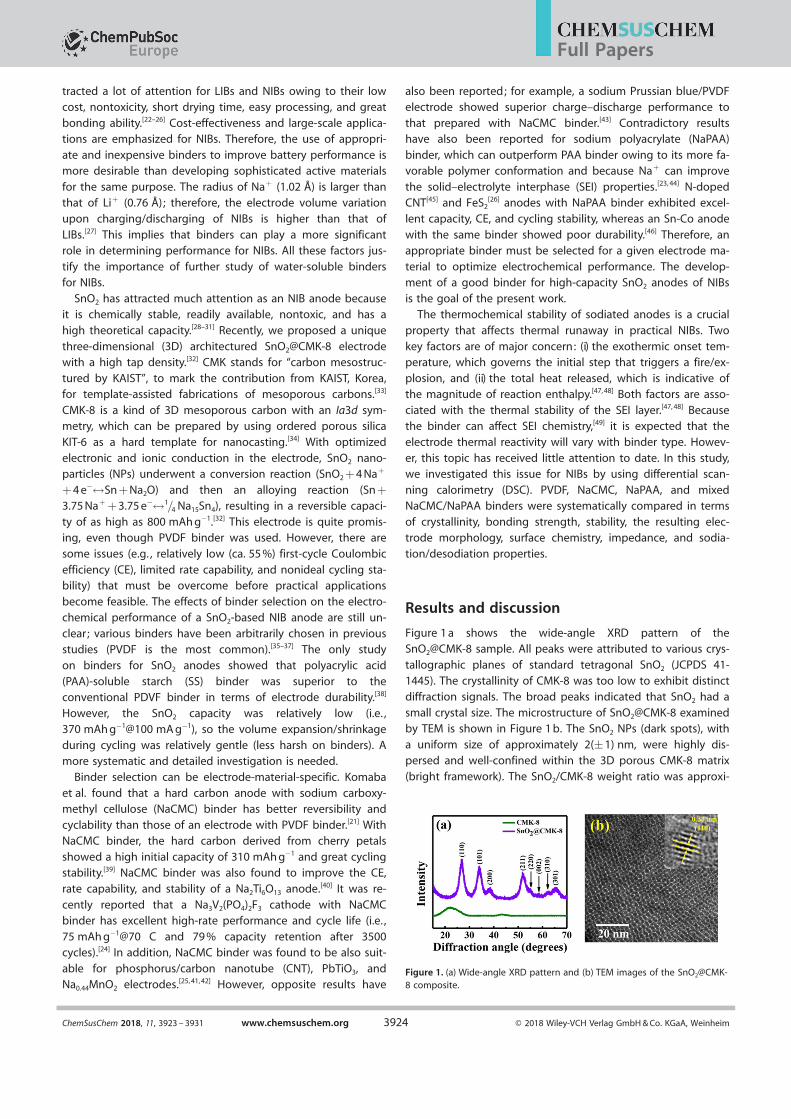
Figure 1 a shows the wide-angle XRD pattern of theSnO2@CMK-8 sample. All peaks were attributed to various crys-
tallographic planes of standard tetragonal SnO2 (JCPDS 41-
1445). The crystallinity of CMK-8 was too low to exhibit distinctdiffraction signals. The broad peaks indicated that SnO2 had a
small crystal size. The microstructure of SnO2@CMK-8 examinedby TEM is shown in Figure 1 b. The SnO2 NPs (dark spots), with
a uniform size of approximately 2(:1) nm, were highly dis-persed and well-confined within the 3D porous CMK-8 matrix
(bright framework). The SnO2/CMK-8 weight ratio was approxi-
Figure 1. (a) Wide-angle XRD pattern and (b) TEM images of the SnO2@CMK-8 composite.
ChemSusChem 2018, 11, 3923 – 3931 www.chemsuschem.org T 2018 Wiley-VCH Verlag GmbH & Co. KGaA, Weinheim3924
Full Papers

mately 85:15.[32] The small-angle XRD data for pristine CMK-8and SnO2@CMK-8 samples are shown in Figure S2 (see the
Supporting Information). The intensities of the 1.18 and 1.38peaks, which corresponded to (211) and (220) superlattice dif-
fractions, respectively, of the CMK-8 highly ordered mesopo-rous structure with an Ia3d symmetry,[50]significantly decreasedafter SnO2 incorporation. This confirmed that most of the mes-opores of CMK-8 were filled with SnO2 NPs.
The thermal stability of the binders was evaluated by TGA;
the obtained data are shown in Figure S3. Considering the hy-drophilicity of NaCMC and NaPAA, the gradual weight lossbefore approximately 150 8C for the two binders was attributedto the removal of absorbed water. NaCMC showed the lowestdecomposition temperature (ca. 300 8C), producing Na2O andNa2CO3.[51] PVDF decomposed at approximately 420 8C with a
huge weight drop of >60 %. NaPAA had the highest thermal
stability (i.e. , the smallest weight loss, 25 %, at the highest tem-perature, 460 8C). For any binder, the decomposition tempera-
ture was much higher than that used for slurry drying (i.e. ,ca. 100 8C); therefore, binder thermal stability was not an issue
during the electrode fabrication process.The bonding ability of the binders was evaluated using peel
tests. Scotch tape was adhered to the electrode and then man-
ually peeled off to test the adhesion. As shown in Figure S4,for the PVDF sample, the active material layer was mostly re-
moved from the substrate. With the NaCMC binder, the adhe-sion between Cu foil and the coating material layer was im-
proved. However, the connection between the SnO2@CMK-8NPs was still not strong, as a clearly detached film was found
on the tape side. The NaPAA binder enhanced the interparticle
adhesion even more, as the amount of SnO2@CMK-8 on thetape was reduced. The highest adhesion strength was found
for NaCMC/NaPAA mixed binder. The carbonyl and carboxylgroups on the binders can form hydrogen bonds between the
polymer chains and interact with SnO2 and the current collec-tor to maintain mechanical stability.[17, 52] In addition to being
an adhesive, NaCMC is also a dispersant,[11, 53] which can modify
the conformation of the mixed binder and increase thenumber of bonding sites with the active material and Cu foil,which reduces the flaw size[54] and leads to excellent adhesionof the electrode.
Figure 2 a shows the initial five cyclic voltammetry (CV)curves of the SnO2@CMK-8 electrode with NaCMC/NaPAA
binder. In the first negative scan, there were small humps atapproximately 1.5–2.0 V, which were associated with the sur-face group reduction at the electrode. The irreversible peak at
approximately 0.8 V was attributed to the decomposition offluoroethylene carbonate and the formation of SEI.[13, 55] A con-
version reaction of SnO2 with Na+ then occurred, whichformed Sn and Na2O. When the potential was scanned towards
even lower voltage (<0.3 V), another cathodic peak arose, indi-
cating the occurrence of Sn-Na alloying reactions (formingNaSn5, NaSn, Na9Sn4, Na15Sn4).[56, 57] Below 0.1 V, Na+ insertion
into the carbon phase can also take place.[58] In the followingpositive scan, the reverse reactions (i.e. , deinsertion, dealloying,
and reconversion) occurred, contributing to the anodic peaks.The CV redox behavior became stable in the subsequent scans.
The voltammetric characteristics of the SnO2@CMK-8 electro-des with other binders were similar, as shown in Figure S5.
The charge–discharge curves of various SnO2@CMK-8 elec-trodes (for the initial five cycles) are shown in Figure 2 b and
Figure S6. The Coulombic inefficiency (CI/1@CE) was ascribedto the partial trapping of Na in SnO2 and the formation of an
SEI layer (i.e. , electrolyte decomposition).[28, 30] Figure 2 c indi-
cates that the first-cycle CE values for the PVDF, NaCMC,NaPAA, and NaCMC/NaPAA electrodes were 53 %, 60 %, 62 %,
and 70 %, respectively (Table 1). The initial efficiency of 70 % isamong the best reported (the mechanism is discussed later),
with efficiencies of 30–45 % common for various SnO2-basedNIB anodes.[30, 38, 55, 59, 60] At the fifth cycle, a CE of 99.3 % was ob-
Figure 2. (a) CV curves of the NaCMC/NaPAA electrode measured at a scanrate of 0.1 mV s@1. (b) Initial five charge–discharge curves of the NaCMC/NaPAA electrode measured at 20 mA g@1. (c) The CE values versus cyclenumber for the electrodes with various binders.
ChemSusChem 2018, 11, 3923 – 3931 www.chemsuschem.org T 2018 Wiley-VCH Verlag GmbH & Co. KGaA, Weinheim3925
Full Papers

tained for the NaCMC/NaPAA electrode at a low charge–dis-charge rate of 20 mA g@1. The data suggest that an appropriate
binder can accommodate the volume change and modify thesurface chemistry of SnO2@CMK-8, improving the reversibility
of the electrode.
XPS was used to examine the surface chemical compositionof the electrodes. The C 1s spectra of the as-prepared electro-
des are shown in Figure 3 a. The peak at approximately284.6 eV corresponds to the binding energy of C@C and C@H
bonds.[61, 62] The PVDF electrode exhibited strong signals at285.5 and 290.6 eV, which were attributed to @CH2@ and
@CF2@ bonds, respectively.[61] For the aqueous binder electro-
des, the 286.7 eV peak was associated with C@O bonding (forNaCMC), and the 288.5 eV peak was ascribed to the @COONa
group (for both NaCMC and NaPAA).[21, 63] Figure 3 b presentsthe Sn 3d spectra of the electrodes, which show similar binding
energies for all binders. The 3d5/2 and Sn 3d3/2 peaks located at487.5 and 496.1 eV, respectively, confirmed that the valence of
Sn was + 4.[32, 64] Interestingly, the normalized peak intensity for
the electrodes decreased in the sequence PVDF>NaCMC>
NaPAA>NaCMC/NaPAA. These results suggested that theNaCMC/NaPAA electrode was best covered by the binder layer,
decreasing the signals from the underlying SnO2. The co-exis-tence of NaCMC and NaPAA led to a synergistic improvement
in homogeneous wetting of the binder on the active particle
surface, consistent with the adhesion testing results (Figure S4)before cycling.
Figure 3 c compares the surface-exposed Sn content levelsof various electrodes before and after five charge–discharge
cycles. It was found that the surface Sn concentration of thePVDF electrode was considerably reduced after cycling, where-
as that of the NaCMC/NaPAA electrode remained almost un-
changed. Continuous electrolyte decomposition (suggested bythe low CE; Figure 2 c), and thus the growth of the SEI layer,
was responsible for the clear decrease in the Sn ratio of thePVDF electrode. Figure 3 d shows the F spectra of the cycled
electrodes. The peak at approximately 687.6 eV for the PVDFelectrode was associated with its @CF2@ bond.[65, 66] All the elec-
trodes showed a new signal at approximately 684.1 eV after cy-
cling, corresponding to NaF within the SEI, which originatedfrom electrolyte decomposition.[66, 67] The low NaF in-
tensity for the NaCMC/NaPAA electrode further sup-ported the suppressed SEI growth.
Figure 4 shows the electrode microstructure devel-opment. Owing to the crystalline nature (Figure S7)
and bundle formation of PVDF chains,[61, 62] PVDF
binder cannot uniformly cover the electrode surface.The electrolyte easily permeated through PVDF andcame into direct contact with the electrode material,leading to a large electrolyte decomposition reaction
and high CI, especially in the first cycle. Moreover,this SEI layer did not seem to be robust enough to
withstand the SnO2 volume change upon charging/discharging (according to Figure 2 c). The repeatedbreakdown and reformation of the SEI layer led to its
thickening like a snow cover. In contrast, the NaCMCand NaPAA binders were fully amorphous (Figure S7)
and can form a relatively continuous surface coatinglayer because of better wetting and spreading prop-
erties on the particle surface, which acted like an ar-
tificial SEI layer (because these binders are reasona-ble ionic conductors but poor electronic conductors),
improving electrode passivation. In addition, thislayer was mechanically stable, minimizing the
growth of the SEI layer.
Table 1. Charge–discharge properties and film densities of SnO2@CMK-8 electrodes with various binders.
Binders First-cycle CE[%]
Max. capacity[a]
[mAh g@1]High rate capacity[b]
[mAh g@1]Rate capability[c]
[%]Cycling retention[d]
[%]Film density[mg cm@3]
PVDF 53 795 325 41 78 0.40NaCMC 60 800 345 43 83 0.47NaPAA 62 810 365 45 85 0.47NaCMC/NaPAA 70 850 425 50 90 0.48
[a] C20 ; at 20 mA g@1. [b] C2000 ; at 2000 mA g@1. [c] C2000/C20. [d] After 300 cycles.
Figure 3. XPS (a) C 1s and (b) Sn 3d spectra of freshly prepared electrodes with variousbinders. (c) Comparison of Sn concentrations of various electrodes before and after fivecharge–discharge cycles. (d) XPS F 1s spectra of various electrodes after five charge–dis-charge cycles.
ChemSusChem 2018, 11, 3923 – 3931 www.chemsuschem.org T 2018 Wiley-VCH Verlag GmbH & Co. KGaA, Weinheim3926
Full Papers

The charge–discharge curves (after five conditioning cycles)
of the SnO2@CMK-8 electrodes measured at various rates areshown in Figure 5 a and Figure S8. At 20 mA g@1, the measured
discharge (desodiation) capacities were 795, 800, 810, and850 mAh g@1 for the electrodes with PVDF, NaCMC, NaPAA, and
NaCMC/NaPAA binders, respectively (Table 1). The NaCMC/
NaPAA mixed binder was the most suitable for the SnO2@CMK-8 electrode. With the unique 3D mesoporous architecture and
appropriate selection of functional binder, the obtained elec-trode capacity of 850 mAh g@1 was superior to most reported
values.[30, 35–38, 55, 59, 60, 64] The great bonding ability of the bindercan increase the utilization of the active material. The thin SEI
layer facilitated Na+ transport across the electrode/electrolyteinterface.[65] Moreover, the carbonyl and carboxyl groups of thebinders could partially participate in the sodiation/desodiation
reaction.[68] As a result, the NaCMC/NaPAA electrode had greatcharge–discharge capacity.
The electrode’s volumetric specific capacity is also a concernfor practical battery applications. The compressed densities ofthe PVDF, NaCMC, NaPAA, and NaCMC/NaPAA layers were 0.40,0.47, 0.47, and 0.48 g cm@3, respectively (including binder and
carbon black; Table 1). The water-soluble binders can more
closely pack the active material particles and reduce the inter-particle space in the electrodes (Figure 4). The volumetric ca-
pacities of these electrodes were calculated to be 254, 301,311, and 326 mAh cm@3, respectively, at 20 mA g@1. Nanostruc-
tured materials usually exhibit low volumetric performance.However, the experimental data confirm that our anode with
an appropriate binder had a much higher volumetric capacity
than that (130 mAh cm@3) of a hard carbon elec-trode, which is the most commonly studied NIB
anode.[69]
The binder effects on the rate capability of the
SnO2@CMK-8 electrodes are shown in Figure 5 b. Ata high rate of 2000 mA g@1, the electrodes with
PVDF, NaCMC, NaPAA, and NaCMC/NaPAA binders
had reversible capacities of 325, 345, 365, and425 mAh g@1, corresponding to 41 %, 43 %, 45 %, and
50 % retention, respectively (Table 1), compared withthe values measured at 20 mA g@1. The reasons for
the performance variation were determined usingelectrochemical impedance spectroscopy (EIS). As re-vealed in the Nyquist plots in Figure 5 c, the spectra
consisted of a semicircle at high frequency and asloping line at low frequency, which can be charac-terized by the equivalent circuit shown in the inset,in which Re, Rct, CPE, and W are the electrolyte resist-ance, interfacial charge transfer resistance, interfacialconstant phase element, and Warburg impedance
associated with Na+ diffusion in the electrode, re-spectively.[30] The Rct values, which are related to theEIS semicircle diameter, were calculated to be 580,
400, 370, and 240 W for the PVDF, NaCMC, NaPAA,and NaCMC/NaPAA electrodes, respectively. The
higher Rct of the PVDF electrode was attributed toits thicker SEI layer (Figure 3 c). The apparent Na+
diffusion coefficients (DNa+) for the electrodes were
calculated from the oblique linear Warburg parts;[64]
the calculated values for these electrodes were 1.7 V
10@16, 3.8 V 10@15, 6.1 V 10@15, and 8.3 V 10@15 cm2 s@1,respectively. The tightly packed SnO2@CMK-8 NPs
can form a favorable Na+ diffusion pathway, whichresulted in an enhanced transport rate. The DNa
+
Figure 4. Scheme of electrode structures with PVDF and NaCMC/NaPAAbinders after charge–discharge cycling.
Figure 5. (a) Charge–discharge curves of NaCMC/NaPAA electrode measured at variousrates. (b) Comparison of reversible capacities of various electrodes measured at variousrates. (c) EIS data of the electrodes with various binders after conditioning cycles. (d) Cy-cling stability data of SnO2@CMK-8 electrodes with various binders measured at100 mA g@1. (e) Rct values of various electrodes with respect to charge–discharge cyclenumber.
ChemSusChem 2018, 11, 3923 – 3931 www.chemsuschem.org T 2018 Wiley-VCH Verlag GmbH & Co. KGaA, Weinheim3927
Full Papers
values of the PVDF and NaCMC/NaPAA electrodes were also es-timated using CV (see Figure S9 for details). The linear relation-
ship between the redox current and the square root of the CVsweep rate indicated that the sodiation/desodiation reactions
were diffusion-controlled. The obtained DNa+ values were 7.2 V
10@16 and 1.2 V 10@14 cm2 s@1, respectively, which were consis-
tent with the EIS data, again confirming the importance of thebinder selection for achieving the desired electrochemicalproperties.
The cycling stability of the various SnO2@CMK-8 electrodeswas evaluated at 100 mA g@1; the results are shown in Fig-ure 5 d. The capacity retention ratios after 300 cycles were78 %, 83 %, 85 %, and 90 % for the PVDF, NaCMC, NaPAA, and
NaCMC/NaPAA electrodes, respectively (Table 1), with the CEvalues saturating at 98.6 %, 99.1 %, 99.2 %, and 99.7 %, respec-
tively. The variation of Rct with the number of cycles for the
electrodes is shown in Figure 5 e. The more pronounced Rct in-crease upon cycling for the PVDF electrode indicated the infe-
rior surface passivation of this electrode. The accumulation ofthe SEI layer, which not only increased the electrode resistance
but also decreased the number of electroactive sites, led tothe capacity fading. In contrast, the adhesive and dispersant
nature of NaCMC,[11] when mixed with NaPAA, improved the
wetting and spreading of the binder on the active particle sur-face. This artificial layer that formed was robust and could sup-
press the SEI evolution, improving the electrode durability. Thecycling stability of the electrodes was further examined at a
high charge–discharge rate of 2000 mA g@1 (Figure S10). After150 cycles, the capacity retention ratios were 56 %, 64 %, 66 %,
and 73 % for the PVDF, NaCMC, NaPAA, and NaCMC/NaPAA
electrodes, respectively. The decreased durability at a high so-diation-desodiation rate suggested that the electrode volume
expansion/shrinkage, rather than other parasitic reactions, wasmainly responsible for the capacity decay. A good binder, even
though it accounts for only a small portion of the electrode,plays a significant role in cycling stability, especially under
high-rate operation. Besides the binder selection, the electrode
cycling stability can also be improved by development of newelectrolyte formulations, electrode architectures, and other pre-
treatment processes.[16, 70, 71]
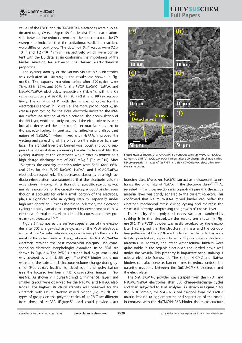
Figure S11 compares the surface appearances of the electro-des after 300 charge–discharge cycles. For the PVDF electrode,some of the Cu substrate was exposed (owing to the detach-
ment of the active material layer), whereas the NaCMC/NaPAAelectrode retained the best mechanical integrity. The corre-sponding electrode morphologies examined using SEM areshown in Figure 6. The PVDF electrode had huge cracks andwas covered by a thick SEI layer. The PVDF binder could not
withstand the substantial electrode volume change during cy-cling (Figures 6 a), leading to decohesion and pulverization
(see the focused ion beam (FIB) cross-section image in Fig-ure 6 e). As shown in Figures 6 b and c, thinner SEI layers andsmaller cracks were observed for the NaCMC and NaPAA elec-
trodes. The highest structural stability was observed for theelectrode with NaCMC/NaPAA mixed binder (Figure 6 d). The
types of groups on the polymer chains of NaCMC are differentfrom those of NaPAA (Figure S1) and could provide extra
bonding sites. Moreover, NaCMC can act as a dispersant to en-
hance the uniformity of NaPAA in the electrode slurry.[11, 53] Asrevealed in the cross-section micrograph (Figure 6 f), the active
material layer was tightly adhered to the current collector. Thisconfirmed that NaCMC/NaPAA mixed binder can buffer the
electrode mechanical stress during cycling and maintain the
structural integrity, suppressing the growth of the SEI layer.The stability of the polymer binders was also examined by
soaking it in the electrolyte; the results are shown in Fig-ure S12. The PVDF powder was easily peptized by the electro-
lyte. This implied that the structural firmness and the conduc-tive pathways of the PVDF electrode can be degraded by elec-
trolyte penetration, especially with high-expansion electrodematerials. In contrast, the other water-soluble binders werequite stable in the organic electrolyte and settled down well
under the vessels. This property is important for sustaining arobust electrode framework. The stable NaCMC and NaPAA
binders can also serve as barrier layers to reduce undesirableparasitic reactions between the SnO2@CMK-8 electrode and
the electrolyte.
The SnO2@CMK-8 powder was scraped from the PVDF andNaCMC/NaPAA electrodes after 300 charge–discharge cycles
and then subjected to TEM analyses. As shown in Figure 7, forthe PVDF sample, the SnO2 NPs had escaped from the CMK-8
matrix, leading to agglomeration and separation of the oxide.In contrast, with the NaCMC/NaPAA binder, the microstructure
Figure 6. SEM images of SnO2@CMK-8 electrodes with (a) PVDF, (b) NaCMC,(c) NaPAA, and (d) NaCMC/NaPAA binders after 300 charge–discharge cycles.FIB cross-section images of (e) PVDF and (f) NaCMC/NaPAA electrodes afterthe same cycles.
ChemSusChem 2018, 11, 3923 – 3931 www.chemsuschem.org T 2018 Wiley-VCH Verlag GmbH & Co. KGaA, Weinheim3928
Full Papers
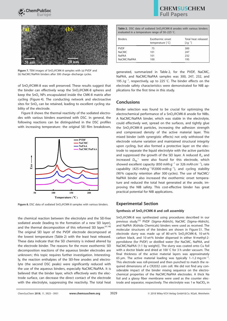
of SnO2@CMK-8 was well preserved. These results suggest thatthe binder can effectively wrap the SnO2@CMK-8 spheres and
keep the SnO2 NPs encapsulated inside the CMK-8 matrix after
cycling (Figure 4). The conducting network and electroactivesites for SnO2 can be retained, leading to excellent cycling sta-
bility of the electrode.Figure 8 shows the thermal reactivity of the sodiated electro-
des with various binders examined with DSC. In general, thefollowing reactions can be distinguished in the DSC profiles
with increasing temperature: the original SEI film breakdown,
the chemical reaction between the electrolyte and the SEI-freesodiated anode (leading to the formation of a new SEI layer),
and the thermal decomposition of this reformed SEI layer.[47, 48]
The original SEI layer of the PVDF electrode decomposed at
the lowest temperature (Table 2) with the least heat released.These data indicate that the SEI chemistry is indeed altered by
the electrode binder. The reasons for the more exothermic SEIdecomposition reactions of the aqueous binder electrodes are
unknown; this topic requires further investigation. Interesting-
ly, the reaction enthalpies of the SEI-free anodes and electro-lyte (the second DSC peaks) were significantly reduced with
the use of the aqueous binders, especially NaCMC/NaPAA. It isbelieved that the binder layer, which effectively wets the elec-
trode surface, can decrease the direct contact of the electrodewith the electrolyte, suppressing the reactivity. The total heat
generated, summarized in Table 2, for the PVDF, NaCMC,NaPAA, and NaCMC/NaPAA samples was 300, 247, 232, and195 J g@1, respectively, up to 225 8C. The binder effects on the
electrode safety characteristics were demonstrated for NIB ap-plications for the first time in this study.
Conclusions
Binder selection was found to be crucial for optimizing theelectrochemical performance of a SnO2@CMK-8 anode for NIBs.
A NaCMC/NaPAA binder, which was stable in the electrolyte,
could effectively wet, spread on the surfaces, and tightly gluethe SnO2@CMK-8 particles, increasing the adhesion strength
and compressed density of the active material layer. Thismixed binder (with synergistic effects) not only withstood the
electrode volume variation and maintained structural integrityupon cycling, but also formed a protective layer on the elec-
trode to separate the liquid electrolyte with the active particles
and suppressed the growth of the SEI layer. A reduced Rct andincreased DNa
+ were also found for this electrode, which
showed excellent capacity (850 mAh g@1 or 326 mAh cm@1), ratecapability (425 mAh g@1@2000 mAh g@1), and cycling stability
(90 % capacity retention after 300 cycles). The use of NaCMC/NaPAA binder also increased the exothermic onset tempera-
ture and reduced the total heat generated at the anode, im-
proving the NIB safety. This cost-effective binder has greatpractical potential for NIB applications.
Experimental Section
Synthesis of SnO2@CMK-8 and cell assembly
SnO2@CMK-8 was synthesized using procedures described in ourprevious study.[32] PVDF (Sigma–Aldrich), NaCMC (Sigma–Aldrich),and NaPAA (Kishida Chemicals) binders were used as received. Themolecular structures of the binders are shown in Figure S1. Theelectrode slurry was made up of 80 wt % SnO2@CMK-8, 10 wt %carbon black, and 10 wt % binder dispersed in either N-methyl-2-pyrrolidone (for PVDF) or distilled water [for NaCMC, NaPAA, andNaCMC/NaPAA (1:1 by weight)] . The slurry was coated onto Cu foilwith a doctor blade and dried at 100 8C for 3 h under vacuum. Thefinal thickness of the active material layers was approximately65 mm. The active material loading was typically 1–1.2 mg [email protected] electrode was roll-pressed and then punched to match the re-quired dimensions of a CR2032 coin cell. We did not find any con-siderable impact of the binder mixing sequence on the electro-chemical properties of the NaCMC/NaPAA electrodes. A thick Nafoil and a glassy fiber membrane were used as the counter elec-trode and separator, respectively. The electrolyte was 1 m NaClO4 in
Figure 7. TEM images of SnO2@CMK-8 samples with (a) PVDF and(b) NaCMC/NaPAA binders after 300 charge–discharge cycles.
Figure 8. DSC data of sodiated SnO2@CMK-8 samples with various binders.
Table 2. DSC data of sodiated SnO2@CMK-8 anodes with various bindersevaluated in a temperature range of 50–225 8C.
Binders Exothermic onsettemperature [8C]
Total heat released[J g@1]
PVDF 75 300NaCMC 101 247NaPAA 101 232NaCMC/NaPAA 100 195
ChemSusChem 2018, 11, 3923 – 3931 www.chemsuschem.org T 2018 Wiley-VCH Verlag GmbH & Co. KGaA, Weinheim3929
Full Papers

propylene carbonate (PC)/ethylene carbonate (EC) mixed solvent(1:1 by volume) with 5 wt % fluoroethylene carbonate (FEC) addi-tive. The assembly of the coin cells was performed in an argon-filled glove box (Innovation Technology Co. Ltd.), in which boththe moisture and oxygen content levels were maintained at below0.5 ppm.
Material and electrochemical characterization
The crystallinity of SnO2@CMK-8 was characterized by X-ray diffrac-tion (XRD; Bruker D8 ADVANCE) using CuKa radiation as the inci-dent X-ray source. The small-angle XRD patterns were recordedwith a Shimadzu LabX XRD-6000 diffractometer with CuKa radia-tion. The morphology and microstructure of the samples were ex-amined using SEM (FEI Inspect F50), a FIB; FEI V ersa 3D), andhigh-resolution TEM (TEM; JEOL 2100F). X-ray photoelectron spec-troscopy (XPS; VG Sigma Probe) was used to analyze the surfacechemical compositions of the electrodes. AlKa radiation (1486.6 eV)was used as the excitation source. All of the acquired spectra werereferenced to the C 1s peak of hydrocarbon at a binding energy of284.6 eV. XPSPEAK 4.1 software was adopted for the data fitting.TGA (PerkinElmer TGA7) were conducted with a heating rate of5 8C min@1 to characterize the thermal stability of the binders. EISwas performed in the frequency range of 100 kHz-10 mHz with anAC amplitude of 10 mV. A Biologic VSP-300 potentiostat was usedfor CV measurements. The charge–discharge properties (such ascapacity, rate performance, and cycling stability) of various electro-des were evaluated using a battery tester (Arbin, BT-2043) at 25 8C.For each condition, at least five coin cells were tested. The per-formance deviation was typically within 5 %. The reported data arethe median values. The thermal reactivity of the sodiatedSnO2@CMK-8 samples with various binders was evaluated usingDSC (Netzsch DSC3500) in a temperature range of 50–225 8C. Thesamples were presodiated to 0.01 V versus Na/Na+ , recoveredfrom the coin cells, placed into Al capsules in the glove box with-out washing and drying, and then transferred to the DSC chamber,which was filled with N2 gas and heated at a rate of 10 8C min@1.
Acknowledgements
The financial support provided for this work by the Ministry of
Science and Technology (MOST) of Taiwan is gratefully appreciat-ed. JL acknowledges the support provided by the National Sci-
ence Foundation (ECCS-1610806).
Conflict of interest
The authors declare no conflict of interest.
Keywords: batteries · binders · electrodes · energy storage ·sodium
[1] J. W. Choi, D. Aurbach, Nat. Rev. Mater. 2016, 1, 16013.[2] H. Kim, H. Kim, Z. Ding, M. H. Lee, K. Lim, G. Yoon, K. Kang, Adv. Energy
Mater. 2016, 6, 1600943.[3] C. Vaalma, D. Buchholz, M. Weil, S. Passerini, Nat. Rev. Mater. 2018, 3,
18013.[4] N. Wongittharom, C. H. Wang, Y. C. Wang, C. H. Yang, J. K. Chang, ACS
Appl. Mater. Interfaces 2014, 6, 17564 – 17570.[5] C. H. Wang, Y. W. Yeh, N. Wongittharom, Y. C. Wang, C. J. Tseng, S. W.
Lee, W. S. Chang, J. K. Chang, J. Power Sources 2015, 274, 1016 – 1023.
[6] H. Y. Li, C. H. Yang, C. M. Tseng, S. W. Lee, C. C. Yang, T. Y. Wu, J. K.Chang, J. Power Sources 2015, 285, 418 – 424.
[7] Y. You, A. Manthiram, Adv. Energy Mater. 2018, 8, 1701785.[8] P. K. Nayak, L. Yang, W. Brehm, P. Adelhelm, Angew. Chem. Int. Ed. 2018,
57, 102 – 120; Angew. Chem. 2018, 130, 106 – 126.[9] P. Ge, M. Fouletier, Solid State Ionics 1988, 28 – 30, 1172 – 1175.
[10] B. Jache, P. Adelhelm, Angew. Chem. Int. Ed. 2014, 53, 10169 – 10173;Angew. Chem. 2014, 126, 10333 – 10337.
[11] W. Zhang, M. Dahbi, S. Komaba, Curr. Opin. Chem. Eng. 2016, 13, 36 – 44.[12] C. Bommier, X. Ji, Small 2018, 14, 1703576.[13] S. Komaba, T. Ishikawa, N. Yabuchi, W. Murata, A. Ito, Y. Ohsawa, ACS
Appl. Mater. Interfaces 2011, 3, 4165 – 4168.[14] P. Arora, Z. Zhang, Chem. Rev. 2004, 104, 4419 – 4462.[15] Q. Zhang, Z. Yu, P. Du, C. Su, Recent Pat. Nanotechnol. 2010, 4, 100 – 110.[16] J. Y. Hwang, S. T. Myung, Y. K. Sun, Chem. Soc. Rev. 2017, 46, 3529 – 3614.[17] S. L. Chou, Y. Pan, J. Z. Wang, H. K. Liu, S. X. Dou, Phys. Chem. Chem.
Phys. 2014, 16, 20347 – 20359.[18] J. T. Li, Z. Y. Wu, Y. Q. Lu, Y. Zhou, Q. S. Huang, L. Huang, S. G. Sun, Adv.
Energy Mater. 2017, 7, 1701185.[19] N. Yabuuchi, K. Kubota, M. Dahbi, S. Komaba, Chem. Rev. 2014, 114,
11636 – 11682.[20] X. Wang, C. Yao, F. Wang, Z. Li, Small 2017, 13, 1702240.[21] M. Dahbi, T. Nankano, N. Yabuchi, T. Ishikawa, K. Kubota, M. Fukunishi,
S. Shibahara, J. Y. Son, Y. T. Cui, H. Oji, S. Komaba, Electrochem. Commun.2014, 44, 66 – 69.
[22] Y. Shi, X. Zhou, G. Yu, Acc. Chem. Res. 2017, 50, 2642 – 2652.[23] S. Komaba, K. Okushi, T. Ozeki, H. Yui, Y. Katayama, T. Miura, T. Saito, H.
Groult, Electrochem. Solid-State Lett. 2009, 12, A107 – A110.[24] J. Zhao, X. Yang, Y. Yao, Y. Gao, Y. Sui, B. Zou, H. Ehrenberg, G. Chen, F.
Du, Adv. Sci. 2018, 5, 1700768.[25] V. Dall’Asta, D. Buchholz, L. G. Chagas, X. Dou, C. Ferrara, E. Quartarone,
C. Tealdi, S. Passerini, ACS Appl. Mater. Interfaces 2017, 9, 34891 – 34899.[26] K. Chen, W. Zhang, L. Xie, W. Chen, X. Xiang, M. Wan, Y. Huang, ACS
Appl. Mater. Interfaces 2017, 9, 1536 – 1541.[27] S. Y. Hong, Y. Kim, Y. Park, A. Choi, N. S. Choi, K. T. Lee, Energy Environ.
Sci. 2013, 6, 2067 – 2081.[28] Z. Li, J. Ding, D. Mitlin, Acc. Chem. Res. 2015, 48, 1657 – 1665.[29] B. Huang, Z. Pan, X. Su, L. An, J. Power Sources 2018, 395, 41 – 59.[30] J. Patra, H. C. Chen, C. H. Yang, C. T. Hsieh, C. Y. Su, J. K. Chang, Nano
Energy 2016, 28, 124 – 134.[31] X. Li, Z. Zhu, G. P. Nayaka, J. Duan, D. Wang, P. Dong, L. Huang, J. Zhao,
S. Sun, X. Yu, Y. Zhang, J. Alloys Compd. 2018, 752, 68 – 75.[32] J. Patra, P. C. Rath, C. H. Yang, D. Saikia, H. M. Kao, J. K. Chang, Nanoscale
2017, 9, 8674 – 8683.[33] R. Ryoo, S. H. Joo, Stud. Surf. Sci. Catal. 2004, 148, 241 – 260.[34] P. C. Rath, J. Patra, D. Saikia, M. Mishra, J. K. Chang, H. M. Kao, J. Mater.
Chem. A 2016, 4, 14222 – 14233.[35] Y. Y. Wang, B. H. Hou, Y. N. Wang, H. Y. Lu, J. Z. Guo, Q. L. Ning, J. P.
Zhang, C. L. Lu, X. L. Wu, J. Mater. Chem. A 2018, 6, 6578 – 6586.[36] M. Dirican, Y. Lu, Y. Ge, O. Yildiz, X. Zhang, ACS Appl. Mater. Interfaces
2015, 7, 18387 – 18396.[37] H. Z. Li, L. Y. Yang, J. Liu, S. T. Li, L. B. Fang, Y. K. Lu, H. R. Yang, S. L. Liu,
M. Lei, J. Power Sources 2016, 324, 780 – 787.[38] Y. Wei, Z. Wang, H. Ye, J. Mou, D. Lei, Y. Liu, W. Lv, B. Li, F. Kang, Y. B. He,
ChemistrySelect 2017, 2, 11365 – 11369.[39] Z. Zhu, F. Liang, Z. Zhou, X. Zeng, D. Wang, P. Dong, J. Zhao, S. Sun, Y.
Zhang, X. Li, J. Mater. Chem. A 2018, 6, 1513 – 1522.[40] Y. Zhang, H. Hou, X. Yang, J. Chen, M. Jing, Z. Wu, X. Jia, X. Ji, J. Power
Sources 2016, 305, 200 – 208.[41] J. Song, Z. Yu, M. L. Gordin, X. Li, H. Peng, D. Wang, ACS Nano 2015, 9,
11933 – 11941.[42] Y. Zhang, M. Ji, Z. Liu, Y. He, Y. Hu, Q. Yang, B. Lia, J. Wang, RSC Adv.
2017, 7, 25678 – 25684.[43] M. J. Piernas-MuÇoz, E. C. Martinez, J. L. G. Camer, T. Rojo, Electrochim.
Acta 2016, 200, 123 – 130.[44] Z. J. Han, K. Yamagiwa, N. Yabuuchi, J. Y. Son, Y. T. Cui, H. Oji, A. Kogure,
T. Harada, S. Ishikawa, Y. Aoki, S. Komaba, Phys. Chem. Chem. Phys.2015, 17, 3783 – 3795.
[45] Q. Fan, W. Zhang, J. Duan, K. Hong, L. Xue, Y. Huang, Electrochim. Acta2015, 174, 970 – 977.
ChemSusChem 2018, 11, 3923 – 3931 www.chemsuschem.org T 2018 Wiley-VCH Verlag GmbH & Co. KGaA, Weinheim3930
Full Papers

[46] Y. Yui, M. Hayashi, K. Hayashi, J. Nakamura, Solid State Ionics 2016, 288,219 – 223.
[47] A. Ponrouch, E. Marchante, M. Courty, J. M. Tarascona, M. R. Palacın,Energy Environ. Sci. 2012, 5, 8572 – 8583.
[48] G. G. Eshetu, S. Grugeon, H. Kim, S. Jeong, L. Wu, G. Gachot, S. Laruelle,M. Arman, S. Passerini, ChemSusChem 2016, 9, 462 – 471.
[49] Y. S. Park, E. S. Oh, S. M. Lee, J. Power Sources 2014, 248, 1191 – 1196.[50] F. Kleitz, S. H. Choi, R. Ryoo, Chem. Commun. 2003, 2136 – 2137.[51] N. Cuesta, A. Romes, I. Camean, C. Antuna, A. B. Garcia, Electrochim.
Acta 2015, 155, 140 – 147.[52] N. P. W. Pieczonka, V. Borgel, B. Ziv, N. Leifer, V. Dargel, D. Aurbach, J. H.
Kim, Z. Liu, X. Huang, S. A. Krachkovskiy, G. R. Goward, I. Halalay, B. R.Powell, A. Manthiram, Adv. Energy Mater. 2015, 5, 1501008.
[53] L. Chen, X. Xie, J. Xie, K. Wang, J. Yang, J. Appl. Electrochem. 2006, 36,1099 – 1104.
[54] H. Gao, B. Ji, I. L. Jager, E. Arzt, P. Fratzl, Proc. Natl. Acad. Sci. USA 2003,100, 5597 – 5600.
[55] H. C. Chen, J. Patra, S. W. Lee, C. J. Tseng, T. Y. Wu, M. H. Lin, J. K. Chang,J. Mater. Chem. A 2017, 5, 13776 – 13784.
[56] J. W. Wang, X. H. Liu, S. X. Mao, J. Y. Huang, Nano Lett. 2012, 12, 5897 –5902.
[57] V. L. Chevrier, G. Ceder, J. Electrochem. Soc. 2011, 158, A1011 – A1014.[58] J. Ding, H. Wang, Z. Li, A. Kohandehghan, K. Cui, Z. Xu, B. Zahiri, X. Tan,
E. M. Lotfabad, B. C. Olsen, D. Mitlin, ACS Nano 2013, 7, 11004 – 11015.[59] Y. X. Wang, Y. G. Lim, M. S. Park, S. L. Chou, J. H. Kim, H. K. Liu, S. X. Dou,
Y. J. Kim, J. Mater. Chem. A 2014, 2, 529 – 534.[60] J. Ding, Z. Li, H. Wang, K. Cui, A. Kohandehghan, X. Tan, D. Karpuzovc,
D. Mitlin, J. Mater. Chem. A 2015, 3, 7100 – 7111.
[61] N. Yabuuchi, K. Shimomura, Y. Shimbe, T. Ozeki, J. Y. Son, H. Oji, Y. Ka-tayama, T. Miura, S. Komaba, Adv. Energy Mater. 2011, 1, 759 – 765.
[62] S. Komaba, N. Yabuchi, T. Ozeki, Z. J. Han, K. Shimomura, H. Yui, Y. Ka-tayama, T. Miura, J. Phys. Chem. C 2012, 116, 1380 – 1389.
[63] S. Komaba, K. Shimomura, N. Yabuchi, T. Ozeki, H. Yui, K. Konno, J. Phys.Chem. C 2011, 115, 13487 – 13495.
[64] L. Fan, X. Li, B. Yan, J. Feng, D. Xiong, D. Li, L. Gu, Y. Wen, S. Lawes, X.Sun, Adv. Energy Mater. 2016, 6, 1502057.
[65] J. Patra, H. T. Huang, W. Xue, C. Wang, A. S. Helal, J. Li, J. K. Chang,Energy Storage Mater. 2019, 16, 146 – 154.
[66] K. Takada, Y. Yamada, E. Watanabe, J. Wang, K. Sodeyama, Y. Tateyama,K. Hirata, T. Kawasa, A. Yamada, ACS Appl. Mater. Interfaces 2017, 9,33802 – 33809.
[67] H. Kim, J. S. Park, S. H. Sahgong, S. Park, J. K. Kim, Y. Kim, J. Mater. Chem.A 2014, 2, 19584 – 19588.
[68] Y. Ein-Eli, V. R. Koch, J. Electrochem. Soc. 1997, 144, 2968 – 2973.[69] X. F. Luo, A. S. Helal, C. T. Hsieh, J. Li, J. K. Chang, Nano Energy 2018, 49,
515 – 522.[70] J. Cui, S. Yao, J. K. Kim, Energy Storage Mater. 2017, 7, 64 – 114.[71] C. Chen, Y. Wen, X. Hu, X. Ji, M. Yan, L. Mai, P. Hu, B. Shan, Y. Huang,
Nat. Commun. 2015, 6, 6929.
Manuscript received: August 25, 2018
Revised manuscript received: September 21, 2018
Accepted manuscript online: September 24, 2018Version of record online: November 8, 2018
ChemSusChem 2018, 11, 3923 – 3931 www.chemsuschem.org T 2018 Wiley-VCH Verlag GmbH & Co. KGaA, Weinheim3931
Full Papers
Supporting Information
A Water-Soluble NaCMC/NaPAA Binder for ExceptionalImprovement of Sodium-Ion Batteries with an SnO2-Ordered Mesoporous Carbon AnodeJagabandhu Patra,[a, b, f] Purna Chandra Rath,[a, b] Chi Li,[a] Hsien-Ming Kao,[c] Fu-Ming Wang,[d]
Ju Li,*[e] and Jeng-Kuei Chang*[a, b, e, f]
cssc_201801962_sm_miscellaneous_information.pdf

Figure S1. Molecular Structures of (a) PVDF, (b) NaCMC, and (c) NaPAA binders.
(a) (b)
(c)

Figure S2. Small-angle XRD patterns of pristine CMK-8 and SnO2@CMK-8 composite.
0 1 2 3 4(2
20
)
(21
1) CMK-8
SnO2@CMK-8
Inte
nsi
ty (
a.u
)
Diffraction angle (degrees)

Figure S3. TGA data of PVdF, NaCMC, and NaPAA binders measured at a heating rate of 5 °C
min–1.
100 200 300 400 500 600 7000
20
40
60
80
100
120
Temperature ( OC )
PVDF
NaCMC
NaPAA
Wei
gh
t (%
)

Figure S4. Peel test results of SnO2@CMK-8 electrodes with (a) PVDF, (b) NaCMC, (c) NaPAA,
and (d) NaCMC/NaPAA electrodes.
(a)
(b)
(c)
(d)
Substrate side Tape side
1 cm

Figure S5. CV curves of (a) PVDF, (b) NaCMC, and (c) NaPAA electrodes measured at a scan
rate of 0.1 mV s−1.
0.0 0.5 1.0 1.5 2.0 2.5 3.0
-0.6
-0.4
-0.2
0.0
0.2
1st cycle
2nd cycle
3rd cycle
4th cycle
5th cycle
Cu
rren
t (m
A)
Potential (V vs. Na/Na+)
(a)
0.0 0.5 1.0 1.5 2.0 2.5 3.0
-0.6
-0.4
-0.2
0.0
0.2
1st cycle
2nd cycle
3rd cycle
4th cycle
5th cycle
Cu
rren
t (m
A)
Potential (V vs. Na/Na+)
(b)
0.0 0.5 1.0 1.5 2.0 2.5 3.0
-0.6
-0.4
-0.2
0.0
0.2
1st cycle
2nd cycle
3rd cycle
4th cycle
5th cycle
Cu
rren
t (m
A)
Potential (V vs. Na/Na+)
(c)

Figure S6. Initial five charge–discharge curves of (a) PVDF, (b) NaCMC, and (c) NaPAA
electrodes measured at 20 mA g–1.
0 400 800 1200 1600
0.0
0.5
1.0
1.5
2.0
2.5
3.0 1st cycle
2nd cycle
3rd cycle
4th cycle
5th cycle
P
ote
nti
al
(V v
s. N
a/N
a+)
Specific capacity (mAh/g)
(a)
0 400 800 1200 1600
0.0
0.5
1.0
1.5
2.0
2.5
3.0 1st cycle
2nd cycle
3rd cycle
4th cycle
5th cycle
Po
ten
tia
l (V
vs.
Na
/Na
+)
Specific capacity (mAh/g)
(b)
0 400 800 1200 1600
0.0
0.5
1.0
1.5
2.0
2.5
3.0 1st cycle
2nd cycle
3rd cycle
4th cycle
5th cycle
Po
ten
tia
l (V
vs.
Na
/Na
+)
Specific capacity (mAh/g)
(c)

Figure S7. XRD patterns of PVDF, NaCMC, and NaPAA binders.
10 20 30 40 50 60
PVDF
NaCMC
NaPAA
Inte
nsi
ty (
a.u
)
Diffraction angle (degrees)

Figure S8. Charge−discharge curves of (a) PVDF, (b) NaCMC, and (c) NaPAA electrodes
measured at various rates.
0 200 400 600 800 1000
0.0
0.5
1.0
1.5
2.0
2.5
3.0
20 mA/g
50 mA/g
100 mA/g
200 mA/g
500 mA/g
1000 mA/g
2000 mA/g
Po
ten
tia
l (V
vs.
Na
/Na
+)
Specific capacity (mAh/g)
(b)
0 200 400 600 800 1000
0.0
0.5
1.0
1.5
2.0
2.5
3.0
20 mA/g
50 mA/g
100 mA/g
200 mA/g
500 mA/g
1000 mA/g
2000 mA/g
Po
ten
tia
l (V
vs.
Na
/Na
+)
Specific capacity (mAh/g)
(c)
0 200 400 600 800 1000
0.0
0.5
1.0
1.5
2.0
2.5
3.0
20 mA/g
50 mA/g
100 mA/g
200 mA/g
500 mA/g
1000 mA/g
2000 mA/g
Po
ten
tia
l (V
vs.
Na
/Na
+)
Specific capacity (mAh/g)
(a)

The linear relationship between the redox current and the square root of the CV sweep rate
indicates that the sodiation/desodiation reactions are diffusion-controlled. Thus, the following
Randles–Sevcik equation is applicable. The apparent Na+ diffusion coefficients can be estimated
according to:
Ip = (2.69 x 10⁵) n3/2 A D1/2 v1/2 Co
0.0 0.5 1.0 1.5 2.0 2.5 3.0
-1.5
-1.0
-0.5
0.0
0.5
1.0
0.1mV/S
0.2 mV/S
0.5 mV/S
0.8 mV/S
1.0 mV/S
2.0 mV/S
Cu
rren
t (m
A)
Potential (V vs. Na/Na+)
(a)
0.0 0.5 1.0 1.5 2.0 2.5 3.0
-1.5
-1.0
-0.5
0.0
0.5
1.0
0.1 mV/s
0.2 mV/s
0.5 mV/s
0.8 mV/s
1.0 mV/s
2.0 mV/s
Cu
rren
t (m
A)
Potential (V vs. Na/Na+)
(b)
0.3 0.6 0.9 1.2 1.50.0
0.2
0.4
0.6
0.8
1.0
D Na+ =
1.2 x 10⁻¹
4 cm2 /se
c
D Na+ =
7.2 x 10⁻¹
6 cm2 /se
c
PVDF
NaCMC/NaPAA
Pea
k C
urr
ent
(mA
)
Square root of scan rate ((mV/s)1/2
)
(c)

where Ip is the peak current, n is the charge-transfer number, A is the geometric area of the
electrode, Co is the concentration of Na+ in electrolyte, v is the potential sweep rate, D is the
apparent diffusion coefficient of Na+.
Figure S9. CV curves of (a) PVDF and (b) NaCMC/NaPAA electrodes measured at various
potential sweep rates. (c) DNa+ calculation plots.

Figure S10. Cycling stability data of SnO2@CMK-8 electrodes with various binders measured at
2000 mA g–1.
0
200
400
600
800
0 60 90 120 150
PVDF
NaPAA
NaCMC
Co
ulo
mb
ic e
fficie
ncy
(%)
Sp
ecif
ic c
ap
acit
y (
mA
h/g
)
Cycle number
NaCMC/NaPAA
30
50
60
70
80
90
100
110
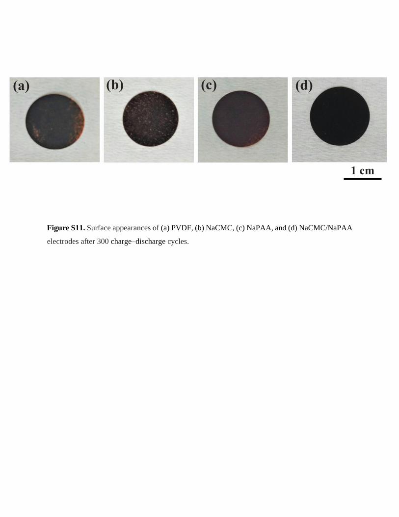
Figure S11. Surface appearances of (a) PVDF, (b) NaCMC, (c) NaPAA, and (d) NaCMC/NaPAA
electrodes after 300 charge–discharge cycles.
1 cm
(a) (b) (c) (d)

Figure S12. Photographs of (a) PVDF, (b) NaCMC, (c) NaPAA, and (d) NaCMC/NaPAA binders
immersed in 1 M NaClO4 PC/EC/FEC electrolyte.
(b) (a)
(c) (d)