avxmu ltilayer ceramic smd feedthru...
TRANSCRIPT
AVX Multilayer Ceramic SMD Feedthru Capacitors
Commercial, Automotive, High Current, RoHS & SnPb Termination
ww
w.a
vx
.com
Version 17.5
Feedthru 0805/1206 CapacitorsTable of Contents
W2F/W2H/W3F Series - 0805 & 1206 Feedthru Chips Commercial, Automotive, High Current, RoHS & SnPb . . . . . . . . . . . . . . . . . . . . . . . . . . . 1Application Notes . . . . . . . . . . . . . . . . . . . . . . . . . . . . . . . . . . . . . . . . . . . . . . . . . . . 5

1
Feedthru 0805/1206 CapacitorsW2F/W3F Series, High Current W2H SeriesCommercial, Automotive, High Current, RoHS & SnPbGENERAL DESCRIPTION
Available in both a standard 0805 and 1206 size, AVX’s line of feedthru capacitors are ideal choices for EMI suppres-sion, broadband I/O filtering, or Vcc power line condition-ing. The unique construction of a feedthru capacitor pro-vides low parallel inductance and offers excellent decou-pling capability for all high di/dt environments and provides significant noise reduction in digital circuits to <5 GHz. A large range of capacitor values are available in either NP0 or X7R ceramic dielectrics. AVX FeedThru filters are AEC Q200 qualified. High reliability screening options, and SnPb termination are available for spacecraft designs.
ELECTRICAL PARAMETERS
SIGNAL LINE - INPUT OUTPUT
GROUND
W2F/W2H Series
0805
W3F Series1206
HOW TO ORDER
W
StyleW = Plated Ni & SnL = Plated SnPb
3
Size2 = 08053 = 1206
F
Feedthru
1
Numberof
Elements
5
Voltage1 = 100V5 = 50V
C
DielectricA = NP0C = X7R
223
CapacitanceCode
8
CapacitanceTolerance
8 = +50/-20%
A
Failure RateA = Not Applicable4 = AUTOMOTIVE
T
TerminationT = Plated Ni & SnB* = Plated SnPb
3
Packaging Code(Reel Size)
1 & 2 = 7" ReelEmbossed Tape3 & 4 = 13" ReelEmbossed Tape
A
QuantityCode
(Pcs./Reel)F = 1,000A = 2,000,4,000 or10,000
Standard SnPb Termination Finish Automotive Automotive w/ SnPb
Termination Finish0805 W2H11A2208ATxx L2H11A2208ABxx W2H11A22084Txx L2H11A22084Bxx 22 100V 0.5 NP0 0805 W2H11A4708ATxx L2H11A4708ABxx W2H11A47084Txx L2H11A47084Bxx 47 100V 0.5 NP0 0805 W2H11A1018ATxx L2H11A1018ABxx W2H11A10184Txx L2H11A10184Bxx 100 100V 0.5 NP0 0805 W2H11A2218ATxx L2H11A2218ABxx W2H11A22184Txx L2H11A22184Bxx 220 100V 0.5 NP0 0805 W2H11A4718ATxx L2H11A4718ABxx W2H11A47184Txx L2H11A47184Bxx 470
+50%, -20%+50%, -20%+50%, -20%+50%, -20%+50%, -20% 100V 0.5 NP0
0805 W2H15C1028ATxx L2H15C1028ABxx W2H15C10284Txx L2H15C10284Bxx 1000 50V 1.0 X7R 0805 W2H15C1038ATxx L2H15C1038ABxx W2H15C10384Txx L2H15C10384Bxx 10000 50V 1.0 X7R 0805 W2H15C2238ATxx L2H15C2238ABxx W2H15C22384Txx L2H15C22384Bxx 22000 50V 1.0 X7R 0805 W2H15C4738ATxx L2H15C4738ABxx W2H15C47384Txx L2H15C47384Bxx 47000 50V 2.0 X7R 0805 W2H13C1048ATxx L2H13C1048ABxx W2H13C10484Txx L2H13C10484Bxx 100000
+50%, -20%+50%, -20%+50%, -20%+50%, -20%+50%, -20% 25V 2.0 X7R
0805 W2F11A2208ATxx L2F11A2208ABxx W2F11A22084Txx L2F11A22084Bxx 22 100V 0.3 NP00805 W2F11A4708ATxx L2F11A4708ABxx W2F11A47084Txx L2F11A47084Bxx 47 100V 0.3 NP00805 W2F11A1018ATxx L2F11A1018ABxx W2F11A10184Txx L2F11A10184Bxx 100 100V 0.3 NP00805 W2F11A2218ATxx L2F11A2218ABxx W2F11A22184Txx L2F11A22184Bxx 220 100V 0.3 NP00805 W2F11A4718ATxx L2F11A4718ABxx W2F11A47184Txx L2F11A47184Bxx 470
+50%, -20%+50%, -20%+50%, -20%+50%, -20%+50%, -20% 100V 0.3 NP0
0805 W2F15C1028ATxx L2F15C1028ABxx W2F15C10284Txx L2F15C10284Bxx 1000 50V 0.3 X7R0805 W2F15C2228ATxx L2F15C2228ABxx W2F15C22284Txx L2F15C22284Bxx 2200 50V 0.3 X7R0805 W2F15C4728ATxx L2F15C4728ABxx W2F15C47284Txx L2F15C47284Bxx 4700 50V 0.3 X7R0805 W2F15C1038ATxx L2F15C1038ABxx W2F15C10384Txx L2F15C10384Bxx 10000 50V 0.3 X7R0805 W2F15C2238ATxx L2F15C2238ABxx W2F15C22384Txx L2F15C22384Bxx 22000 50V 0.3 X7R0805 W2F15C4738ATxx L2F15C4738ABxx W2F15C47384Txx L2F15C47384Bxx 47000
+50%, -20%+50%, -20%+50%, -20%+50%, -20%+50%, -20%+50%, -20% 50V 0.3 X7R
1206 W3F11A2208ATxx L3F11A2208ABxx W3F11A22084Txx L3F11A22084Bxx 22 100V 0.3 NP01206 W3F11A4708ATxx L3F11A4708ABxx W3F11A47084Txx L3F11A47084Bxx 47 100V 0.3 NP01206 W3F11A1018ATxx L3F11A1018ABxx W3F11A10184Txx L3F11A10184Bxx 100 100V 0.3 NP01206 W3F11A2218ATxx L3F11A2218ABxx W3F11A22184Txx L3F11A22184Bxx 220 100V 0.3 NP01206 W3F11A4718ATxx L3F11A4718ABxx W3F11A47184Txx L3F11A47184Bxx 470
+50%, -20%+50%, -20%+50%, -20%+50%, -20%+50%, -20% 100V 0.3 NP0
1206 W3F15C1028ATxx L3F15C1028ABxx W3F15C10284Txx L3F15C10284Bxx 1000 50V 0.3 X7R1206 W3F15C2228ATxx L3F15C2228ABxx W3F15C22284Txx L3F15C22284Bxx 2200 50V 0.3 X7R1206 W3F15C4728ATxx L3F15C4728ABxx W3F15C47284Txx L3F15C47284Bxx 4700 50V 0.3 X7R1206 W3F15C1038ATxx L3F15C1038ABxx W3F15C10384Txx L3F15C10384Bxx 10000 50V 0.3 X7R1206 W3F15C2238ATxx L3F15C2238ABxx W3F15C22384Txx L3F15C22384Bxx 22000 50V 0.3 X7R1206 W3F15C4738ATxx L3F15C4738ABxx W3F15C47384Txx L3F15C47384Bxx 47000
+50%, -20%+50%, -20%+50%, -20%+50%, -20%+50%, -20%+50%, -20% 50V 0.3 X7R
Rated Current(Amps)
Dielectric
Hig
h C
urre
ntSt
anda
rd
Type Case Size(EIA)
AVX Part NumberCapacitance
(pF)Capacitance
ToleranceRated
DC Voltage
Parameter High Current StandardInsulation Resistance (Minimum) 1000 MΩ 1000 MΩ
DC Resistance <0.15 Ω <0.60 Ω
Operating Temperature -55C to +125C
xx = Packaging and quantity code - see "How To Order" section.
*Not RoHS Compliant
SIGNAL LINE - INPUT OUTPUT
GROUND
F = FeedhtruH= High Current
Feedthru
050817

2
T
P
LC
P
S W
BW
T
SX
L CL
EW
WBL
Feedthru Pad Feedthru Pad
Common Ground
Common Ground
DIMENSIONS
RECOMMENDED SOLDER PAD LAYOUT (TYPICAL DIMENSIONS)
L W T BW BL EW X S
0805 MM 2.01 ± 0.20 1.25 ± 0.20 1.14 Max. 0.46 ± 0.10 0.18 + 0.25 -0.08 0.25 ± 0.13 1.02 ± 0.10 0.23 ± 0.15(in.) (0.079 ± 0.008) (0.049 ± 0.008) (0.045 Max.) (0.018 ±0.004) (0.007 + 0.010 -0.003) (0.010 ± 0.005) (0.040 ± 0.004) (0.009 ± 0.006)
1206 MM 3.20 ± 0.20 1.60 ± 0.20 1.27 Max. 0.89 ± 0.10 0.18 + 0.25 -0.08 0.38 ± 0.18 1.60 ± 0.10 0.46 ± 0.15(in.) (0.126 ± 0.008) (0.063 ± 0.008) (0.050 Max.) (0.035 ± 0.004) (0.007 + 0.010 -0.003) (0.015 ± 0.007) (0.063 ± 0.004) (0.018 ± 0.006)
T P S W L C
0805 MM 3.45 0.51 0.76 1.27 1.02 0.46(in.) (0.136) (0.020) (0.030) (0.050) (0.040) (0.018)
1206 MM 4.54 0.94 1.02 1.65 1.09 0.71(in.) (0.179) (0.037) (0.040) (0.065) (0.043) (0.028)
TYPICAL FEEDTHRU CHIP CAP CONNECTION
Feedthru Chip Component Model Physical Layout - A
Physical Layout - B
Vcc orSignal In
Signal In
The terminals are connected internally side to side.Left side and right side are connected and front and back are connected internally. For Decoupling, the chip is usually surrounded by four vias, two for Vcc and two for GND.For Signal Filtering, the in and out lines need to beseparated on the circuit board.
Vcc orSignal Out
Signal Out
Ground
Ground
Ground
Vcc Vcc
Ground
Ground
Feedthru 0805/1206 CapacitorsW2F/W3F Series, High Current W2H SeriesCommercial, Automotive, High Current, RoHS & SnPb
3
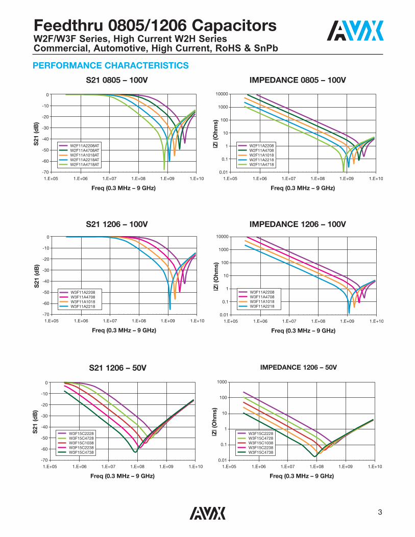
PERFORMANCE CHARACTERISTICS
S21 0805 – 100V IMPEDANCE 0805 – 100V
S21 1206 – 100V IMPEDANCE 1206 – 100V
S21 1206 – 50V IMPEDANCE 1206 – 50V
0
-10
-20
-30
-40
-50
-60
-701.E+05 1.E+06 1.E+07 1.E+08 1.E+09 1.E+10
Freq (0.3 MHz – 9 GHz)
S21
(dB
)
10000
1000
100
10
1
0.1
0.011.E+05 1.E+06 1.E+07 1.E+08 1.E+09 1.E+10
Freq (0.3 MHz – 9 GHz)
|Z| (
Ohm
s)
W2F11A2208ATW2F11A4708ATW2F11A1018ATW2F11A2218ATW2F11A4718AT
W2F11A2208W2F11A4708W2F11A1018W2F11A2218W2F11A4718
0
-10
-20
-30
-40
-50
-60
-701.E+05 1.E+06 1.E+07 1.E+08 1.E+09 1.E+10
Freq (0.3 MHz – 9 GHz)
S21
(dB
)
10000
1000
100
10
1
0.1
0.011.E+05 1.E+06 1.E+07 1.E+08 1.E+09 1.E+10
Freq (0.3 MHz – 9 GHz)
|Z| (
Ohm
s)
W3F11A2208W3F11A4708W3F11A1018W3F11A2218
W3F11A2208W3F11A4708W3F11A1018W3F11A2218
0
-10
-20
-30
-40
-50
-60
-701.E+05 1.E+06 1.E+07 1.E+08 1.E+09 1.E+10
Freq (0.3 MHz – 9 GHz)
S21
(dB
)
1000
100
10
1
0.1
0.011.E+05 1.E+06 1.E+07 1.E+08 1.E+09 1.E+10
Freq (0.3 MHz – 9 GHz)
|Z| (
Ohm
s)
W3F15C2228W3F15C4728W3F15C1038W3F15C2238W3F15C4738
W3F15C2228W3F15C4728W3F15C1038W3F15C2238W3F15C4738
Feedthru 0805/1206 CapacitorsW2F/W3F Series, High Current W2H SeriesCommercial, Automotive, High Current, RoHS & SnPb

4
PERFORMANCE CHARACTERISTICS
30.00
35.00
40.00
25.00
20.000.3 0.5 0.7
Current (A)
Com
pon
ent
Tem
per
atur
e (°
C)
0.8 1.00 1.20
100pf220pf
47pf
470pf
30.00
35.00
40.00
25.00
20.000.3 0.5 0.7
Current (A)
Com
pon
ent
Tem
per
atur
e (°
C)
0.8 1.00 1.20
1000pf2200pf
4700pf
10nf
47nf
22nf
100pf 22pf 47pf 470pf 220pf
40.00
20.00
0.000.3 0.5 0.75
Current (A)
0.87 1.00 1.20
Com
pon
ent
Tem
per
atur
e (°
C)
2200pf
40.00
20.00
0.000.3 0.5 0.75
Current (A)
Com
pon
ent
Tem
per
atur
e (°
C)
0.87 1.00 1.20
22,000pf1000pf
0805 NP0
Current vs. Temperature
0805 X7R
Current vs. Temperature
1206 NP0
Current vs. Temperature
1206 X7R
Current vs. Temperature
Feedthru 0805/1206 CapacitorsW2F/W3F Series, High Current W2H SeriesCommercial, Automotive, High Current, RoHS & SnPb

5REV 01
Feedthru 0805/1206 CapacitorsW2F/W3F Series
APPLICATIONSEMI SuppressionBroadband I/O FilteringVcc Line Conditioning
FEATURESStandard EIA SizesBroad Frequency ResponseLow ESR8 mm Tape and Reel
MARKET SEGMENTSComputersAutomotivePower SuppliesMultimedia Add-On CardsBar Code Scanners and Remote TerminalsPCMCIA CardsMedical InstrumentationTest EquipmentTransceivers/Cell Phones
Applications
Typical Circuits RequiringEMI Filtering
THE FOLLOWING APPLICATIONS AND SCHEMATIC DIAGRAMS SHOW WHEREFEEDTHRU CAPACITORS MIGHT BE USED FOR EMI SUPPRESSION
• Digital to RF Interface Filtering• Voltage Conditioning in RF Amplifiers• Power Decoupling GaAs FET Transistor Preamplifier• Vcc Line Filtering on Frequency Control Circuit• Clock, Data, Control Line High Frequency Decoupling (Frequency Synthesizer)
(SEE APPLICATION NOTES)
Audio
Digital�Block
RF�Block
= Feedthru
DIGITAL TO RF INTERFACE FILTERING

6 REV 01
S.M. = SILVER MICA
RFC1FB
L3
Q1
G D
SL4
L5
R2
R1
R3
L6
1N914
D1D2
L1 L2
J2OUTPUT
J1INPUT
C2
C3
C5
OUT INGND
U178L05C4
C1 C8
C60.1
C70.1
1.5pFTYPICAL
5.6S.M.
621/4W
511/8W
16V0.4W
1000F.T.
15S.M.
200CHIP500
POT
200CHIP
200CHIP
+12/14V14mA
= Feedthru
OUT
C85
C87
2
0.022
C8282 D25
1N914
2N5486 Q25
R1361M
R141100
R140100
R139100k
R138100k
R13747k
C8450
C910.022
C890.022
C8610
C880.022
C90
T14
C8124pF
C8082
L3C83
24
VCC
INGND
To Bilateral Mixer
U10
Reg78L05
6-6.35 MHz VFO
FB1
Q2640673
+
2.2μF16V
= Feedthru
Feedthru 0805/1206 CapacitorsW2F/W3F Series
= Feedthru
Q1
Z1
Z3
Z2
Z4
Z5
+28V
+28V
RFC7
RFC8
RFC1
RFC5
RFC6
R6D1
C9
C1
C5
C2 C3
C7 C8 C15
C26 C20
C14
C21
C22
C23
C24
C16C6
C4 C11 C12
C25 C18
C13
C10
R1
T1
RF in
RF Out
T2
R4
R2
R3
R5
L1
Filter
L2
L3
RFC2
RFC4
RFC3
+28V
Z7
Z6
Z8
Q2
Q4
Q3
VOLTAGE CONDITIONING IN RF AMPLIFIERS
POWER DECOUPLING GaAs FET TRANSISTOR PREAMPLIFIER
Vcc LINE FILTERING ON FREQUENCY CONTROL CIRCUIT

7REV 01
High Current Feedthru CapacitorsW2H Series
APPLICATIONS
Dual Power Switch Filtering
PCMCIACard
I/O BusController
3.3V 3VIN
5VIN5V
W2H15C1048AT1A W2H15C1038AT1A
VC120630D650
RF OUT
TransGuard
PA Filtering

8 REV 01
Feedthru 0805/1206 CapacitorsW2F/W2H/W3F Series
EMI REDUCTION THROUGH THE USE OF SMT FEEDTHRU CAPACITORS
ABSTRACTToday’s high speed, miniaturized semiconductors havemade EMI issues a key design consideration. This paperbriefly defines EMI and illustrates the capability of SMTfeedthru capacitors.
WHAT IS EMI?The term EMI stands for Electromagnetic Interference andrefers to signals/energy interfering with a circuit or systemsfunctions.In an electronic system, two classes of energy are generated- wanted and unwanted. Both are potential sources of EMI(1).Wanted signals such as clocks and bus lines could causeEMI if they were not decoupled, terminated or filtered prop-erly. Unwanted signals (cell phones, police radios, powersupply noise, etc.) could be conducted or radiated into thecircuit due to poor circuit layout, improper decoupling or alack of high frequency filtering.In either type of EMI signal interference, the system could berendered useless or put into a state which would cause earlyfailure of its semiconductors. Even worse, the unwantedenergy could cause an incorrect answer to be generatedfrom a computer by randomly powering a gate up or down. From all of this we can gather that EMI is a complex prob-lem, usually with no one solution. EMI interference can be arandom single shot noise (like a SCR firing) or repetitive innature (stepper motor or relay noise). The interference canenter into our designs either by being induced by E/B fields,or it can be conducted through control lines or a communi-cation bus. EMI can even be self generated by internal com-ponents that generate steep risetime waveforms of voltageor current.
HOW CAN EMI BE CONTROLLED? EMI is most efficiently controlled by realizing it to be a designparameter in the earliest stages of the design. This way, theboard layout can be optimized with large power and groundplanes which will be low impedance in nature. The use ofSMT feedthru filters will yield optimal results.
SMT FEEDTHRU CAPACITORSAVX introduced feedthru capacitors to supply a broadbandEMI filter capacitor for source suppression and receiver noisereduction.SMT feedthru capacitors use the same material systems asstandard ceramic capacitors. They exhibit the same reliabili-
ty and can be processed in the same end user productionmethods as standard capacitors. What feedthru capacitorsoffer is an optimized frequency response across a wide RFspectrum due to a modified internal electrode design.An application comparison between an SMT feedthru and adiscrete capacitor is shown in Figure 1.
The key difference between the two filtering methods is thatthe feedthru has a much lower inductance between the sig-nal line and ground than the capacitor. The difference ininductances can be in the range of roughly one order mag-nitude with a feedthru capacitor. This inductance can beshown in an electrical sense through the model for a feedthruand a capacitor (Figure 2).
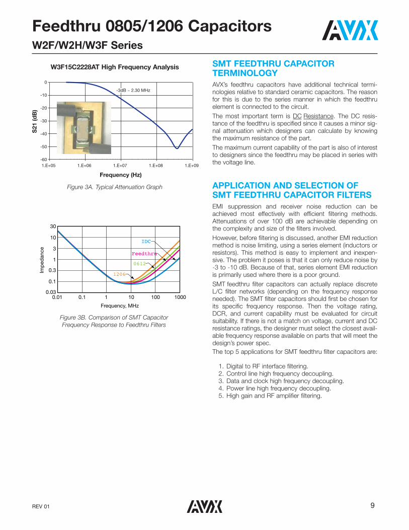
The feedthru capacitor has a minimized parallel inductanceand an optimal series inductance (which broadens the frequency response curve). Typical attenuation graphs areshown in Figure 3A.These curves demonstrate feedthru capacitors advantage ofa broad frequency response with high attenuation. They alsoserve as a comparison to the inductance of even lowerinductance devices (primarily used in extreme decouplingcases and switch mode power supplies) - see Figure 3B.
(1)Practical Design for Electromagnetic Compatibility edited by Rocco F. FicchiHayden Book Company 1978
INPUT
FEEDTHRU FILTER
OUTPUT
Signal Trace Signal Trace
INPUT
SMT CAPACITOR
OUTPUT
Signal Trace Signal Trace
Figure 1. Comparison of Feedthru Capacitors
to Discrete Capacitors
Figure 2. Comparison of Feedthru Capacitors
to Discrete Capacitors
FEEDTHRU FILTER
OUTPUTINPUT OUTPUTINPUT
SMT CAPACITOR
9REV 01
Feedthru 0805/1206 CapacitorsW2F/W2H/W3F Series
SMT FEEDTHRU CAPACITOR TERMINOLOGYAVX’s feedthru capacitors have additional technical termi-nologies relative to standard ceramic capacitors. The reasonfor this is due to the series manner in which the feedthruelement is connected to the circuit.The most important term is DC Resistance. The DC resis-tance of the feedthru is specified since it causes a minor sig-nal attenuation which designers can calculate by knowingthe maximum resistance of the part.The maximum current capability of the part is also of interestto designers since the feedthru may be placed in series withthe voltage line.
APPLICATION AND SELECTION OF SMT FEEDTHRU CAPACITOR FILTERSEMI suppression and receiver noise reduction can beachieved most effectively with efficient filtering methods.Attenuations of over 100 dB are achievable depending onthe complexity and size of the filters involved.However, before filtering is discussed, another EMI reductionmethod is noise limiting, using a series element (inductors orresistors). This method is easy to implement and inexpen-sive. The problem it poses is that it can only reduce noise by-3 to -10 dB. Because of that, series element EMI reductionis primarily used where there is a poor ground.SMT feedthru filter capacitors can actually replace discreteL/C filter networks (depending on the frequency responseneeded). The SMT filter capacitors should first be chosen forits specific frequency response. Then the voltage rating,DCR, and current capability must be evaluated for circuitsuitability. If there is not a match on voltage, current and DCresistance ratings, the designer must select the closest avail-able frequency response available on parts that will meet thedesign’s power spec.The top 5 applications for SMT feedthru filter capacitors are:
0
-10
-20
-30
-40
-50
-601.E+05 1.E+06 1.E+07 1.E+08 1.E+09
Frequency (Hz)
S21
(dB
)
-3dB ~ 2.30 MHz
1206
0612
Feedthru
IDC
0.03
0.1
0.3
1
3
10
30
Imp
edan
ce
Frequency, MHz
10001001010.10.01
Figure 3B. Comparison of SMT Capacitor
Frequency Response to Feedthru Filters
Figure 3A. Typical Attenuation Graph
W3F15C2228AT High Frequency Analysis
1. Digital to RF interface filtering.2. Control line high frequency decoupling.3. Data and clock high frequency decoupling.4. Power line high frequency decoupling.5. High gain and RF amplifier filtering.

S-FTCA0M815 -C
A KYOCERA GROUP COMPANY
http://www.avx.com
Contact:
AVX Greenville, SCTel: 864-967-2150
AVX Limited, EnglandTel: +44-1276-697000
AVX S.A.S., FranceTel: +33-1-69-18-46-00
AVX GmbH, GermanyTel: +49-0811-95949-0
AVX SRL, ItalyTel: +39-02-614-571
AVX Czech RepublicTel: +420-57-57-57-521
AVX/ELCO UKTel: +44-1638-675000
ELCO Europe GmbHTel: +49-2741-299-0
AVX S.A., SpainTel: +34-91-63-97-197
AVX BeneluxTel: +31-187-489-337
AVX/Kyocera (S) Pte Ltd.,Singapore
Tel: +65-6286-7555
AVX/Kyocera, Asia, Ltd.,Hong Kong
Tel: +852-2363-3303
AVX/Kyocera Yuhan Hoesa,South Korea
Tel: +82-2785-6504
AVX/Kyocera HK Ltd., Taiwan
Tel: +886-2-2656-0258
AVX/Kyocera (M) Sdn Bhd,Malaysia
Tel: +60-4228-1190
AVX/Kyocera InternationalTrading Co. Ltd.,
ShanghaiTel: +86-21-3255 1933
AVX/Kyocera Asia Ltd.,Shenzen
Tel: +86-755-3336-0615
AVX/Kyocera InternationalTrading Co. Ltd.,
BeijingTel: +86-10-6588-3528
AVX/Kyocera India Liaison Office
Tel: +91-80-6450-0715
AMERICAS EUROPE ASIA-PACIFIC
KED Hong Kong Ltd.Tel: +852-2305-1080/1223
KED Hong Kong Ltd.Shenzen
Tel: +86-755-3398-9600
KED Company Ltd.Shanghai
Tel: +86-21-3255-1833
KED Hong Kong Ltd.Beijing
Tel: +86-10-5869-4655
KED Taiwan Ltd.Tel: +886-2-2950-0268
KED Korea Yuhan Hoesa,South Korea
Tel: +82-2-783-3604/6126
KED (S) Pte Ltd.Singapore
Tel: +65-6509-0328
Kyocera CorporationJapan
Tel: +81-75-604-3449
ASIA-KED(KYOCERA Electronic Devices)