avera distributing
TRANSCRIPT
High-technology antennas designed and manufactured in ITALYHigh-technology antennas designed and manufactured in ITALY 44
666
7,89,1011151617181920
21,2221,22
262727282930
31,32
636
37,3837,3837,38
31,3231,32
3
39,4039,4039,40
1213,1413,14
1223,2423,2423,2423,24
2535
33,3433,3433,34
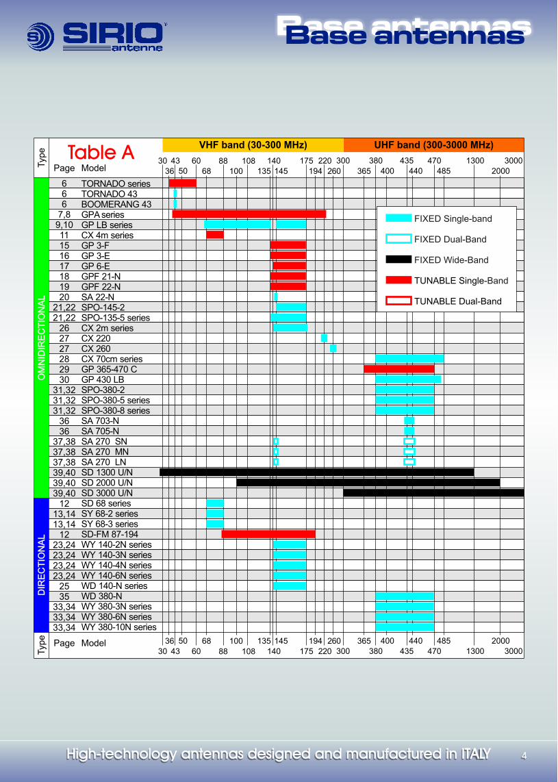
TORNADO seriesTORNADO 43BOOMERANG 43GPA seriesGP LB seriesCX 4m seriesGP 3-FGP 3-EGP 6-EGPF 21-NGPF 22-NSA 22-NSPO-145-2SPO-135-5 seriesCX 2m seriesCX 220CX 260CX 70cm series GP 365-470 CGP 430 LBSPO-380-2SPO-380-5 series SPO-380-8 seriesSA 703-NSA 705-N SA 270 SNSA 270 MNSA 270 LNSD 1300 U/NSD 2000 U/NSD 3000 U/NSD 68 seriesSY 68-2 seriesSY 68-3 seriesSD-FM 87-194WY 140-2N seriesWY 140-3N seriesWY 140-4N seriesWY 140-6N seriesWD 140-N seriesWD 380-NWY 380-3N series WY 380-6N series WY 380-10N series
UHF band (300-3000 MHz)
Base antennasBase antennas
Table A Page
Model
Page
Model
365
300 380 470
485
30001300
2000
435
400 440
30 60
36
43 88
68 135
140
145
175 220
260194 365300 380 470
485
30001300
2000
108
100435
50 400 440
DIR
EC
TIO
NA
LD
IRE
CT
ION
AL
OM
NID
IRE
CT
ION
AL
OM
NID
IRE
CT
ION
AL
VHF band (30-300 MHz)
30 60
36
43 8868 135
140
145
175 220
260194108
10050
FIXED Single-band
FIXED Dual-Band
TUNABLE Single-Band
FIXED Wide-Band
TUNABLE Dual-Band
Typ
e
Typ
e
Page
Model
High-technology antennas designed and manufactured in ITALYHigh-technology antennas designed and manufactured in ITALY55
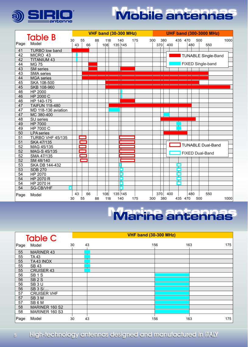
UHF band (300-3000 MHz)VHF band (30-300 MHz) Table B
Page
Model30
664388
135
140
145
175
370
300 380 470
480
1000500
550118 43555
400
414242444343444545
47474748494950515152525252535354545454
464646
TURBO low bandMICRO 43TITANIUM 43MG 75SM seriesSMA seriesMGA seriesSKA 108-500SKB 108-960HP 2000HP 2000 CHP 140-175TAIFUN 118-480MD 118-136 aviationMC 380-400SU seriesHP 7000HP 7000 CLPA seriesTURBO VHF 45/135SKA 47/135MAG 45/135MAG-S 45/135SMA 47/135SM 48/140SKA DB 144-432SDB 270HP 2070HP 2070 RHP 2070 HSG-CB/VHF
Page
Model
VHF band (30-300 MHz) Table C
Page
Model 30 43 156 163 175
5555555555565656565757575858
MARINER 43TA 43TA 43 INOXSB 43CRUISER 43SB 1 SSB 2 SSB 3 USB 3 S/....CRUISER VHFSB 3 MSB 6 MMARINER 160 S2MARINER 160 S3
108
30
6643
88
135
140
145
175
370300 380 470
480
1000500
550
118 43555
400108
30 43 156 163 175
FIXED Dual-Band
TUNABLE Dual-Band
FIXED Single-band
TUNABLE Single-Band
Mobile antennasMobile antennas
Marine antennasMarine antennas
Base antennasBase antennas
High-technology antennas designed and manufactured in ITALYHigh-technology antennas designed and manufactured in ITALY3939
Vertical whipmounting
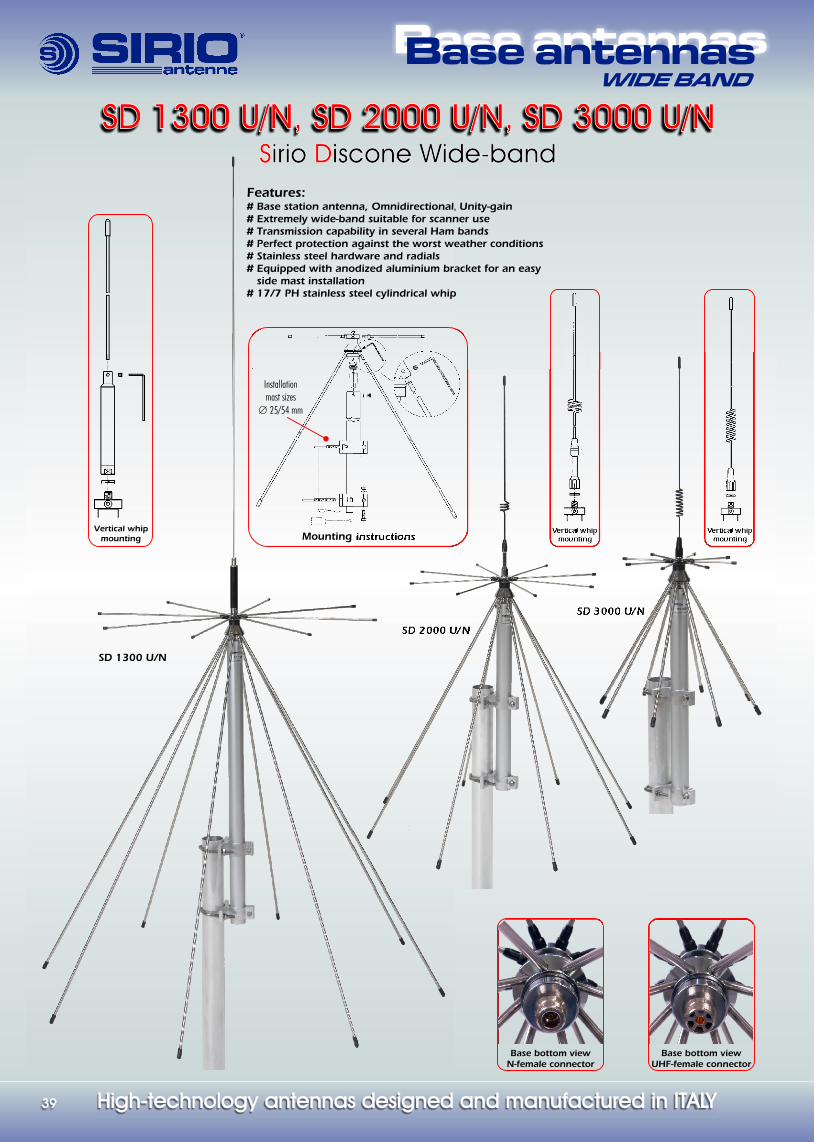
Features:# Unity-gain#
Base station antenna, Omnidirectional, Extremely wide-band suitable for scanner use
# Transmission capability in several Ham bands# Perfect protection against the worst weather conditions# Stainless steel hardware and radials# Equipped with anodized aluminium bracket for an easy side mast installation# 17/7 PH stainless steel cylindrical whip
Mounting instructions
Base bottom viewUHF-female connector
Base bottom viewN-female connector
SD 1300 U/N, SD 2000 U/N, SD 3000 U/NSD 1300 U/N, SD 2000 U/N, SD 3000 U/N
SD 1300 U/N
SD 3000 U/N
SD 2000 U/N
Vertical whipmounting
Vertical whipmounting
Installation mast sizes
25/54 mmÆ
WIDE BAND
irio iscone Wide-bandS D Sirio Discone Wide-band
Base antennasBase antennasWIDE BAND
High-technology antennas designed and manufactured in ITALYHigh-technology antennas designed and manufactured in ITALY 4040
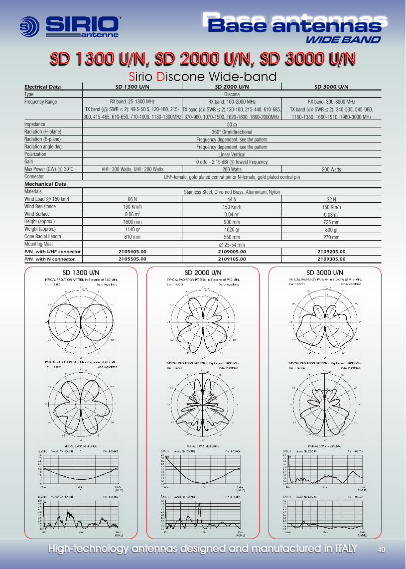
Electrical Data
Type
Frequency Range
Impedance
Radiation (H-plane)
Radiation (E-plane)
Radiation angle deg.
Polarization
Gain
Max Power (CW) @ 30°C
Connector
Mechanical Data
Materials
Wind Load @ 150 km/h
Wind Resistance
Wind Surface
Height (approx.)
Weight (approx.)
Cone Radial Length
Mounting Mast
P/N with UHF connector
P/N with N connector
SD 1300 U/N SD 2000 U/N SD 3000 U/N
SD 1300 U/N
RX band: 25-1300 MHz
TX band (@ SWR 2): 49.5-50.5, 120-180, 215-
300, 415-465, 610-650, 710-1000, 1130-1300MHz
VHF: 300 Watts, UHF: 200 Watts
66 N
130 Km/h20.06 m
1600 mm
1140 gr
810 mm
2105405.00
2105505.00
£
SD 2000 U/N
Discone
RX band: 100-2000 MHz
TX band (@ SWR 2):130-160, 215-440, 610-685,
870-960, 1070-1500, 1620-1800, 1860-2000MHz
50
360° Omnidirectional
Frequency dependent, see the pattern
Frequency dependent, see the pattern
Linear Vertical
0 dBd - 2.15 dBi @ lowest frequency
200 Watts
Stainless Steel, Chromed Brass, Aluminium, Nylon
44 N
150 Km/h20.04 m
900 mm
1020 gr
550 mm
mm2109005.00
2109105.00
£
W
Æ 25-54
SD 3000 U/N
RX band: 300-3000 MHz
TX band (@ SWR 2): 340-535, 545-960,
1180-1380, 1660-1910, 1980-3000 MHz
200 Watts
32 N
150 Km/h20.03 m
725 mm
830 gr
270 mm
2109205.00
2109305.00
£
SD 1300 U/N, SD 2000 U/N, SD 3000 U/NSD 1300 U/N, SD 2000 U/N, SD 3000 U/N irio iscone Wide-bandS D Sirio Discone Wide-band
UHF-female, gold plated central pin or N-female, gold plated central pin

AccesspriesAccessories
High-technology antennas designed and manufactured in ITALYHigh-technology antennas designed and manufactured in ITALY5959
“S” MountFrequency Range: from DC to 300 MHz
Mounting Hole: 19 mmOverall Size: 42 mm.
1 “S” Chrome .............................. 2501002.012 “S” Black ................................. 2501002.02
Æ Æ
“ABN” Trunk MountFixing Hole: 16 mmMaterial: Painted Steel
Æ
ABN Black .................................... 2504105.00
“SL” MountFrequency Range: from DC to 500 MHzOverall Size: 39 mmMounting Hole: 19 mm
Æ Æ
1 “SL” Chrome ............................ 2501102.012 “SL” Black ............................... 2501102.02
“Screw & Bolt”Materials: Chrome plated Brass and Zamak 1 Chrome ..................................... 2506206.002 Black ........................................ 2506207.00
“SL-S” MountFrequency Range: from DC to 500 MHzOverall Size: 39 mmMounting Hole: 19 mm
Æ Æ
“SL-S” Black ............................... 2501102.04
“Wing Bolt”Materials: Chrome plated Brass1 Chrome .................................... 2506306.002 Black ....................................... 2506307.00
“FT-2 Universal”, “FT-3”, “FT-4” Fixing BracketTop Size for antenna fitting: FT-2, FT-4= 38 mm, FT-3= 30 mmBottom Size: FT-2= 45/50 mm mast fitting, FT-3= 35/54 mm mast fitting, FT-4=2x 9 mm wall fitting (screws not included). Weight (approx.): FT-2=1100 gr, FT-3=350gr, FT-4=780grMaterial: FT-2, FT-4=Galvanized Steel, FT-3=Anodized aluminium, Stailess steelFT-2 Universal ............... 2510004.00, FT-3 ............... 2511301.00, FT-4 ............... 2513404.00
Æ Æ
Æ Æ Æ
“ML” MountFrequency Range: from DC to 1000 MHzOverall Size: 30mmMounting Hole: 14 or 18 mm
Æ Æ
“ML” ........................................... 2501202.06
“Safety Set”Materials: Chrome plated Brass and Zamak 1 Chrome .................................... 2506506.002 Black ....................................... 2506507.00
“M-1”, “M-2” Marine BracketsDimension: M1:38x64x98mm, M2:38x100x180mmMaterial: Stainless Steel. Mounting Hole: 2x 16mm1 M-1 Marine Bracket .................. 2503503.002 M-2 Marine Bracket .................. 2503203.003 With Optional fixing set .................................. ........... 2503203.00/SA or 2503503.00/SA
Æ
“M-3” Marine MountConnection: standard 1”x14 threadsDimension L x W x H : 60 x 95 x 130 mmWeight (approx.): 860 grMaterials: Chromed Brass, Stainless steel hardwareM-3 OT Marine Mount .................. 2503606.00
“M-8 “Marine MountConnection: standard 1”x14 threadsDimension L x W x H : 67 x 94 x 124 mmWeight (approx.): 330 grMaterials: Nylon, Stainless steel hardwareM-8 NY Marine Mount ................... 2503301.00
“M-10” Marine MountConnection: standard 1”x14 threadsFixing diameter: 1”Weight (approx.): 600 grMaterials: Chromed Brass, Stainless steel hardwareM-10 OT Marine Mount ................. 2503406.00
1 21 2
1 2 1
2
“KF” Gutter MountFixing Hole: 16 mmMaterial: Painted Zamak
1+2 KF Black w/Cable SO239 ..... 2504205.20
Æ
1 KF Black only ........................... 2504205.00
“TRUNK TOP 2” MountCable / Connector: 5.5m RG 58 / UHF-maleConnection: UHF-female or DV jointDV to PL Chrome ............................ 2504406.12DV to PL Black ............................... 2504407.13
1
2
3
Optional Screw & Bolt Optional Wing Bolt
2. 4m cable w/SO239 & PL259 connected
1. KF black
1
2
FT-2 FT-3 FT-4

AccesspriesAccessories
High-technology antennas designed and manufactured in ITALYHigh-technology antennas designed and manufactured in ITALY 6060
“Antennas’ Dispenser”Overall Dimension W x H: 86 x 230 cm Material: Painted steel. Max weight capacity: 20 KgAntenna's dispenser .................................................................. 32.0002
“MAG H 12” Magnet MountFrequency Range: from DC to 500 MHz. Overall size: 92 mmMaterials: Ferrite magnet, Chromed Brass, Nylon, Rubber protectionCable / Connector: 3.6 m RG 58 / PL 259 R maleMAG H 12 PL ..................................................................... 2502502.05MAG H 12 S ...................................................................... 2502502.01MAG H 12 S Black .............................................................. 2502502.02MAG H 12 3/8 ................................................................... 2502502.03
Æ “MAG 125” Magnet Mount
Frequency Range: from DC to 500 MHz. Overall size: 127 mmMaterials: Ferrite magnet, Chromed Brass, Nylon, Rubber protectionCable / Connector: 3.6 m RG 58 / PL 259 R maleMAG 125 PL ...................................................................... 2502602.05MAG 125 S ....................................................................... 2502602.01MAG 125 S Black ............................................................... 2502602.02MAG 125 3/8 .................................................................... 2502602.03
Æ
“MAG 160” Magnet MountFrequency Range: from DC to 500 MHz. Overall size: 166 mmMaterials: Chromed Brass, Nylon, Magnetic RubberCable / Connector: 3.6 m RG 58 / PL 259 R maleMAG 160 PL ...................................................................... 2502802.05MAG 160 S ....................................................................... 2502802.01MAG 160 S Black ............................................................... 2502802.02MAG 160 3/8 .................................................................... 2502802.03
Æ
AVAILABLE CONNECTION
MAG .... STiltable Joint Chromed or black
MAG .... PLUHF-female connector
MAG .... 3/83/8” connection
“MAG 145” Magnet MountFrequency Range: from DC to 500 MHz. Overall size: 160 mmMaterials: Ferrite magnet, Chromed Brass, Nylon, Rubber protectionCable / Connector: 3.6 m RG 58 / PL 259 R male
......................................MAG 145 S ....................................................................... 2502702.01MAG 145 S Black ............................................................... 2502702.02MAG 145 3/8 .................................................................... 2502702.03
Æ
MAG 145 PL .................... ............ 2502702.05
“HP MAG H 12 PL” Magnet MountFrequency Range: from DC to 500 MHzOverall size: 92 mmMaterials: Ferrite magnet, Chromed Brass, Nylon, Rubber protection, Teflon insulator, Gold plated pinCable: 3.6m RG58 C/U MIL C17HP MAG H 12 PL .............................................................. 2511802.05
Æ
“HP MAG 125 PL” Magnet MountFrequency Range: from DC to 500 MHzOverall size: 127 mmMaterials: Ferrite magnet, Chromed Brass, Nylon, Rubber protection, Teflon insulator, Gold plated pinCable: 3.6m RG58 C/U MIL C17HP MAG 125 PL ................................................................ 2511202.05
Æ
“HP-AC/U” Angular ConnectorFrequency Range: from DC to 500 MHz. Materials: Brass nichel plated, Teflon insulator, 5m RG58 C/U MIL C17HP-AC/U ......................................................................... 2510805.00
“Antennas Display”Materials: Silver painted zamak with rubber gasketFixing Hole: 8 x 12.5 mmANTENNAS DISPLAY ......................................................... 2508008.00
Æ
Metal CapMetal Cap
FME/UHF-male adaptor
Metal Cap
FME/UHF-male adaptorPlastic locking key
Angular connector w/ 5m RG 58 C/U & FME-f
Cables & ConnectorsCables & Connectors
High-technology antennas designed and manufactured in ITALYHigh-technology antennas designed and manufactured in ITALYHigh-technology antennas designed and manufactured in ITALYHigh-technology antennas designed and manufactured in ITALY6161
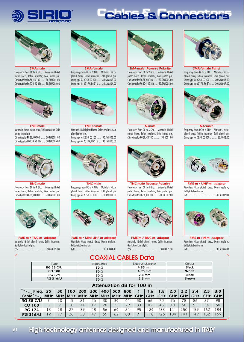
SMA-femaleFrequency: from DC to 9 GHz. Materials: Nickel plated brass, Teflon insulator, Gold plated pin.Crimp type for RG 58, CO 100 ...... 30.SMA003.00Crimp type for RG 174, RG 316 .... 30.SMA004.00
SMA-maleFrequency: from DC to 9 GHz. Materials: Nickel plated brass, Teflon insulator, Gold plated pin.Crimp type for RG 58, CO 100 ...... 30.SMA001.00Crimp type for RG 174, RG 316 .... 30.SMA002.00
N-maleFrequency: from DC to 6 GHz. Materials: Nickel plated brass, Teflon insulator, Gold plated pin.Crimp type for RG 58, CO 100 .......... 30.N001.00
N-femaleFrequency: from DC to 6 GHz. Materials: Nickel plated brass, Teflon insulator, Gold plated pin.Crimp type for RG 58, CO 100 .......... 30.N002.00
FME-maleMaterials: Nickel plated brass, Teflon insulator, Gold plated central pin.Crimp type for RG 58, CO 100 ....... 30.FME001.00Crimp type for RG 174, RG 316 .... 30.FME005.00
FME-femaleMaterials: Nickel plated brass, Delrin insulator, Gold plated central pin.Crimp type for RG 58, CO 100 ....... 30.FME002.00Crimp type for RG 174, RG 316 .... 30.FME003.00
FME-m / UHF-m adaptorMaterials: Nickel plated brass, Delrin insulator, Gold plated central pin.P/N ............................................. 30.AD002.00
COAXIAL CABLES DataType
RG 58 C/UCO 100RG 174
RG 316/U
Impedance50 50 50 50
WWWW
External diameter 4.95 mm4.95 mm2.8 mm2.5 mm
ColourBlackWhiteBlackBrown
Freq. CableRG 58 C/U
CO 100RG 174
RG 316/U
25MHz
75
1312
50MHz107
1817
100MHz15102726
200MHz21143938
300MHz26174847
400MHz30205655
500MHz34236462
800MHz44298480
1GHz50339591
1.6GHz6642
124118
1.8GHz7045
133126
2.0GHz7648
141134
2.2GHz7850
150141
2.4GHz8653
159149
2.5GHz8754
162152
3.0GHz9860
184169
Attenuation dB for 100 m
FME-m / BNC-m adaptorMaterials: Nickel plated brass, Delrin insulator, Gold plated central pin.P/N ............................................. 30.AD005.00
FME-m / N-m adaptorMaterials: Nickel plated brass, Delrin insulator, Gold plated central pin.P/N ............................................. 30.AD006.00
FME-m / Mini UHF-m adaptorMaterials: Nickel plated brass, Delrin insulator, Gold plated central pin.P/N ............................................. 30.AD004.00
FME-m / TNC-m adaptorMaterials: Nickel plated brass, Delrin insulator, Gold plated central pin.P/N ............................................. 30.AD003.00
TNC-maleFrequency: from DC to 4 GHz. Materials: Nickel plated brass, Teflon insulator, Gold plated pin.Crimp type for RG 58, CO 100 ....... 30.TNC001.00
BNC-maleFrequency: from DC to 4 GHz. Materials: Nickel plated brass, Teflon insulator, Gold plated pin.Crimp type for RG 58, CO 100 ....... 30.BNC001.00
TNC-male Reverse PolarityFrequency: from DC to 4 GHz. Materials: Nickel plated brass, Teflon insulator, Gold plated pin.Crimp type for RG 58, CO 100 ....... 30.TNC002.00
SMA-female PanelFrequency: from DC to 9 GHz. Materials: Nickel plated brass, Teflon insulator, Gold plated pin.Crimp type for RG 58, CO 100 ...... 30.SMA008.00Crimp type for RG 174, RG 316 .... 30.SMA007.00
SMA-male Reverse PolarityFrequency: from DC to 9 GHz. Materials: Nickel plated brass, Teflon insulator, Gold plated pin.Crimp type for RG 58, CO 100 ...... 30.SMA005.00Crimp type for RG 174, RG 316 .... 30.SMA006.00
High-technology antennas designed and manufactured in ITALYHigh-technology antennas designed and manufactured in ITALY 6262
Introduction to the radiation patterns coordinate and plotting.The technical data published on this catalog have been measured by means of the
last generation of sophisticated equipment to minimise doubts or mistakes on
measurements. When comparing two radiation diagrams you should keep into
consideration following points:
# Check that all patterns in this catalog have been normalized ( the outside of the
pattern is the maximum gain of the antenna).
# A very important point to remember it is that the shape of a pattern ( its general
appearance ) is highly dependent on the grid system used for the plotting.
# Our radiation polar patterns are represented in 30 dB logarithmic grid scale like
most part of manufacturers. The main goal of such diagrams is to amplify the
maximum gain area to better show all details.
Gain measurement methods.The gain values for base and marine antennas are expressed in dBd (Decibel
relative to 1/2 wave dipole) and they are the result of the comparison between the
reference antenna, in this case the 1/2 wave dipole, and the antenna to test. Same
measurement method is used for vehicular antennas but the difference is the
reference antenna which is a 1/4 wave whip mounted on centre car roof. It's
possible to calculate the gain value in dBi (decibel relative to Isotropic radiator) or
in dBd (decibel relative to 1/2 wave dipole) by adding or deducting 2.14 to the
available value. If the available value is expressed in dBd you should add 2.14 to
get the equivalent in dBi (Ex: 3 dBd + 2.14 = 5.14 dBi); if the value is expressed in
dBi you should deduct 2.14 to get the equivalent value in dBd (Ex: 5.14 dBi - 2.14
= 3 dBd).
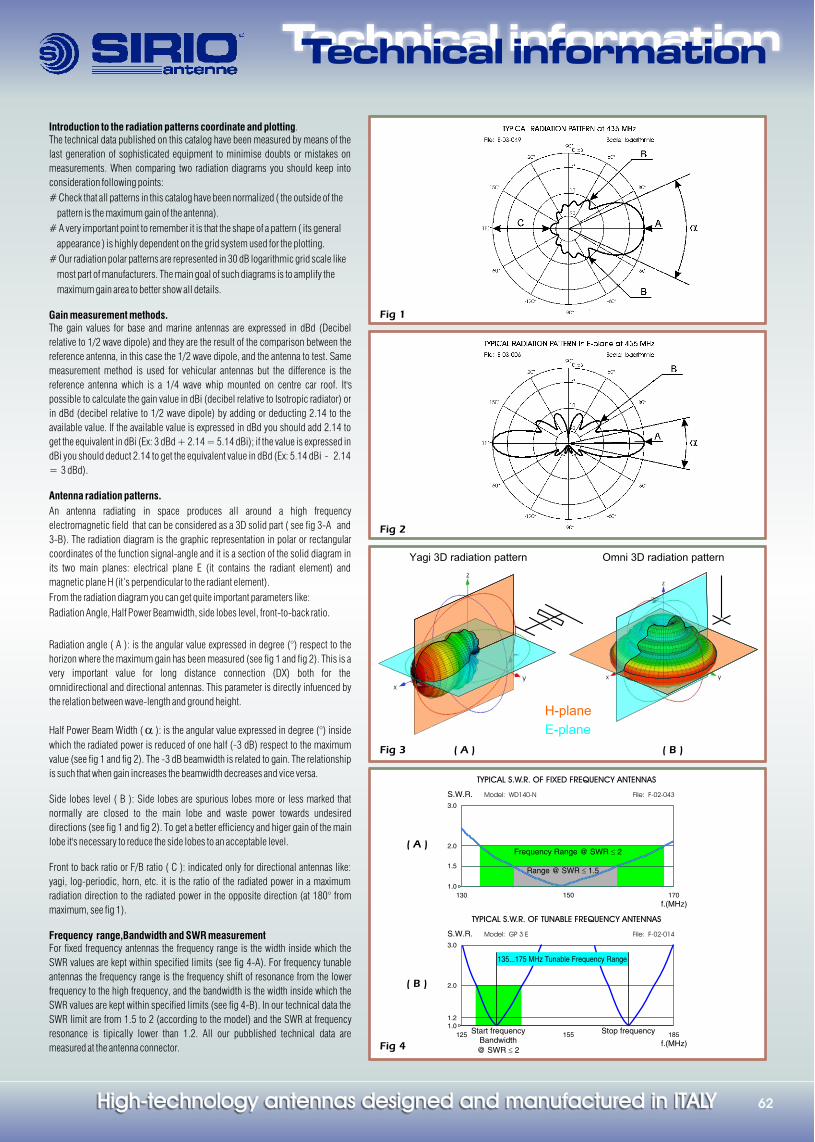
Antenna radiation patterns.
An antenna radiating in space produces all around a high frequency
electromagnetic field that can be considered as a 3D solid part ( see fig 3-A and
3-B). The radiation diagram is the graphic representation in polar or rectangular
coordinates of the function signal-angle and it is a section of the solid diagram in
its two main planes: electrical plane E (it contains the radiant element) and
magnetic plane H (it’s perpendicular to the radiant element).
From the radiation diagram you can get quite important parameters like:
Radiation Angle, Half Power Beamwidth, side lobes level, front-to-back ratio.
Radiation angle ( A ): is the angular value expressed in degree (°) respect to the
horizon where the maximum gain has been measured (see fig 1 and fig 2). This is a
very important value for long distance connection (DX) both for the
omnidirectional and directional antennas. This parameter is directly infuenced by
the relation between wave-length and ground height.
Half Power Beam Width ( a ): is the angular value expressed in degree (°) inside
which the radiated power is reduced of one half (-3 dB) respect to the maximum
value (see fig 1 and fig 2). The -3 dB beamwidth is related to gain. The relationship
is such that when gain increases the beamwidth decreases and vice versa.
Side lobes level ( B ): Side lobes are spurious lobes more or less marked that
normally are closed to the main lobe and waste power towards undesired
directions (see fig 1 and fig 2). To get a better efficiency and higer gain of the main
lobe it's necessary to reduce the side lobes to an acceptable level.
Front to back ratio or F/B ratio ( C ): indicated only for directional antennas like:
yagi, log-periodic, horn, etc. it is the ratio of the radiated power in a maximum
radiation direction to the radiated power in the opposite direction (at 180° from
maximum, see fig 1).
Frequency range,Bandwidth and SWR measurementFor fixed frequency antennas the frequency range is the width inside which the
SWR values are kept within specified limits (see fig 4-A). For frequency tunable
antennas the frequency range is the frequency shift of resonance from the lower
frequency to the high frequency, and the bandwidth is the width inside which the
SWR values are kept within specified limits (see fig 4-B). In our technical data the
SWR limit are from 1.5 to 2 (according to the model) and the SWR at frequency
resonance is tipically lower than 1.2. All our pubblished technical data are
measured at the antenna connector.
Fig 1
Fig 2
Fig 4
Fig 3 ( A ) ( B )
Technical informationTechnical information
TYPICAL S.W.R. OF FIXED FREQUENCY ANTENNAS
Model: WD140-NS.W.R.
1.0
1.5
2.0
3.0
130 150 170
f.(MHz)
File: F-02-043
Frequency Range @ SWR 2£
Range @ SWR 1.5£
High-technology antennas designed and manufactured in ITALYHigh-technology antennas designed and manufactured in ITALY 6262
Introduction to the radiation patterns coordinate and plotting.The technical data published on this catalog have been measured by means of the
last generation of sophisticated equipment to minimise doubts or mistakes on
measurements. When comparing two radiation diagrams you should keep into
consideration following points:
# Check that all patterns in this catalog have been normalized ( the outside of the
pattern is the maximum gain of the antenna).
# A very important point to remember it is that the shape of a pattern ( its general
appearance ) is highly dependent on the grid system used for the plotting.
# Our radiation polar patterns are represented in 30 dB logarithmic grid scale like
most part of manufacturers. The main goal of such diagrams is to amplify the
maximum gain area to better show all details.
Gain measurement methods.The gain values for base and marine antennas are expressed in dBd (Decibel
relative to 1/2 wave dipole) and they are the result of the comparison between the
reference antenna, in this case the 1/2 wave dipole, and the antenna to test. Same
measurement method is used for vehicular antennas but the difference is the
reference antenna which is a 1/4 wave whip mounted on centre car roof. It's
possible to calculate the gain value in dBi (decibel relative to Isotropic radiator) or
in dBd (decibel relative to 1/2 wave dipole) by adding or deducting 2.14 to the
available value. If the available value is expressed in dBd you should add 2.14 to
get the equivalent in dBi (Ex: 3 dBd + 2.14 = 5.14 dBi); if the value is expressed in
dBi you should deduct 2.14 to get the equivalent value in dBd (Ex: 5.14 dBi - 2.14
= 3 dBd).
Antenna radiation patterns.
An antenna radiating in space produces all around a high frequency
electromagnetic field that can be considered as a 3D solid part ( see fig 3-A and
3-B). The radiation diagram is the graphic representation in polar or rectangular
coordinates of the function signal-angle and it is a section of the solid diagram in
its two main planes: electrical plane E (it contains the radiant element) and
magnetic plane H (it’s perpendicular to the radiant element).
From the radiation diagram you can get quite important parameters like:
Radiation Angle, Half Power Beamwidth, side lobes level, front-to-back ratio.
Radiation angle ( A ): is the angular value expressed in degree (°) respect to the
horizon where the maximum gain has been measured (see fig 1 and fig 2). This is a
very important value for long distance connection (DX) both for the
omnidirectional and directional antennas. This parameter is directly infuenced by
the relation between wave-length and ground height.
Half Power Beam Width ( a ): is the angular value expressed in degree (°) inside
which the radiated power is reduced of one half (-3 dB) respect to the maximum
value (see fig 1 and fig 2). The -3 dB beamwidth is related to gain. The relationship
is such that when gain increases the beamwidth decreases and vice versa.
Side lobes level ( B ): Side lobes are spurious lobes more or less marked that
normally are closed to the main lobe and waste power towards undesired
directions (see fig 1 and fig 2). To get a better efficiency and higer gain of the main
lobe it's necessary to reduce the side lobes to an acceptable level.
Front to back ratio or F/B ratio ( C ): indicated only for directional antennas like:
yagi, log-periodic, horn, etc. it is the ratio of the radiated power in a maximum
radiation direction to the radiated power in the opposite direction (at 180° from
maximum, see fig 1).
Frequency range,Bandwidth and SWR measurementFor fixed frequency antennas the frequency range is the width inside which the
SWR values are kept within specified limits (see fig 4-A). For frequency tunable
antennas the frequency range is the frequency shift of resonance from the lower
frequency to the high frequency, and the bandwidth is the width inside which the
SWR values are kept within specified limits (see fig 4-B). In our technical data the
SWR limit are from 1.5 to 2 (according to the model) and the SWR at frequency
resonance is tipically lower than 1.2. All our pubblished technical data are
measured at the antenna connector.
Fig 1
Fig 2
Fig 4
Fig 3 ( A ) ( B )
Technical informationTechnical information
TYPICAL S.W.R. OF FIXED FREQUENCY ANTENNAS
Model: WD140-NS.W.R.
1.0
1.5
2.0
3.0
130 150 170
f.(MHz)
File: F-02-043
Frequency Range @ SWR 2£
Range @ SWR 1.5£
z
x y
z
x
y
Yagi 3D radiation pattern Omni 3D radiation pattern
TYPICAL S.W.R. OF TUNABLE FREQUENCY ANTENNAS
Model: GP 3 ES.W.R.
1.01.2
2.0
3.0
125 155 185
f.(MHz)
File: F-02-014
Start frequencyBandwidth
@ SWR 2£
135...175 MHz Tunable Frequency Range
Stop frequency
H-plane
E-plane
( A )
( B )

Antennas designed and manufactured in ItalyAntennas designed and manufactured in Italy
SIRIO ANTENNE Srl, via Liguria 1546049 Volta Mantovana, MN - ITALY
Ph. +39 0376 801515, Fax +39 0376 801254www.sirioantenne.it [email protected]
Wh
ile th
e in
form
ati
on
has
been
care
fully c
om
piled
to th
e b
est
of
our
kn
ow
led
ge,
noth
ing
is
inte
nd
ed
as
repre
sen
tati
on
or
warr
an
ty on
our
part
an
d n
o st
ate
men
t h
ere
in sh
all be
con
stru
ed
as
reco
mm
en
dati
on
to in
fran
ge e
xis
tin
g p
ate
nts
.SIR
IO A
NTEN
NE r
ese
rves
the r
igh
t to
ch
an
ge o
n a
ny t
ime
an
d w
ith
out
pri
or
warn
ing
th
e te
chn
ical
speci
fica
tion
on
an
y
pro
du
ct
in
this
cata
log
ue.
Co
pyri
gh
t ©
20
08
An
ten
nas
Cata
log
ue V
HF-U
HF H
AM
20
08
fir
st e
dit
ion
P/N
31
.00
02