available to the public analysis and moving base simulation of transition ... · pdf...
TRANSCRIPT
V
NASA CR-114698Available to the Public
ANALYSIS AND MOVING BASE SIMULATION
OF TRANSITION CONFIGURATION MANAGEMENT
ASPECTS OF A POWERED LIFT AIRCRAFT
Walter ..A. Johnson.Samuel. J. Craig
Irving L. Ashkenas
December 1973
STI TR 1015-2
Distribution of this report is providedin the interest of information exchange.Responsibility for the contents resides inthe author or organization that prepared it.
Prepared under contract NAS2-6441 bySYSTEMS TECHNOLOGY, INC.
13766 South Hawthorne BoulevardHawthorne, California 90250
for
Ames Research Center
NATIONAL AERONAUTICS AND SPACE ADMINISTRATION
https://ntrs.nasa.gov/search.jsp?R=19740014558 2018-05-20T02:37:48+00:00Z

Page Intentionally Left Blank

FOREWORD
The research reported here was sponsored by the Ames Research Center,
National Aeronautics and Space Administration. It was conducted by Systems
Technology, Inc., Hawthorne, California, under Contract No. 32-6 41 with
NASA support for the simulation experiments. The NASA Project Monitors
were James A., Franklin "arid Everett A. Palmer.
The authors would like to express their gratitude to the NASA personnel
for their excellent cooperation throughout the experiments; special thanks
to James Franklin and the NASA pilots who acted as subjects — Gordon H.
Hardy and Robert C. Innis. Their patience, and many helpful suggestions,
are greatly appreciated.
TR-1015-2 ii

TABLE OF CONTENTS
I. INTRODUCTION 1
A. General 1
B. Specific 1
II. ANALYSIS 5
A. Trim "Corridor" Considerations 3
B. Possibilities for Improved Trim Managementand Control 15
III. SIMULATION PLAN 23
A. Task Outline 23
B. Control System Types and Operational Implications ... 25
C. Disturbance Environment 29
D. Test Procedures and Tasks 31
IV. RESULTS 33
V. CONCLUSIONS 50
REFERENCES 51
TR-1015-2 iii

LIST OP FIGURES
1 . Generic Plot of Operational Window for Constant Speedand Flight Path Angle (or ax)
2. Generic View of Available and Desirable Trim States . . . . 5
3- Performance Curves for Augmentor Wing Aircraft ...... 7
k. Nozzle vs. Flap Trim Curves for Augmentor Wing Aircraft . . .10
5- Range of Desirable, Constant Throttle, Trim Conditionsfor Transition ................. 1^
6. Flap-Nozzle Relationships for Level Flight(y = ax =0) Transition .............. 17
7- Schematic Block Diagram of Automatic Speed Control System . . 19
8. Vehicle Configurations During Conversion to STOL and NominalTransition with 7 = ax = 0 ............. 20
9- Bode Plot of V/VC closedLoop, with RCAH SAS at V = 80 kt . . . 22
10. Views of Overhead and Console Control Levers,and Cockpit Instruments .............. 2k
1 1 . Block Diagram of Rate -Command Attitude -Hold Pitch SAS . . . . JO
12. Manual with Schedule, Smooth Air, Overhead Control ..... 35
13- Manual with Interconnect, Still Air, Console Control,Pilot A ................... 37
I1)-. Manual with Interconnect, Turbulence and Shear,Console Control, Pilot A . . . . ......... 38
15- Manual with Interconnect Mode> Turbulence and Shear,Button Flap Control, Pilot B ............ kO
16. Manual with Interconnect Mode, Turbulence and Shear, Overhead(Detented) Flap Control, Pilot B ........... Ul
17. Manual with Interconnect, Turbulence, Detented Flap,Decelerate/Accelerate, Pilot B
18. Automatic Mode, No SAS, Turbulence and Shear, Glide SlopeControl with Throttle, Pilot B ........... kk
TR-1015-2

19. Automatic Mode, No SAS, Turbulence and Shear, Glide SlopeControl with Attitude (e), Pilot B
20. Automatic Mode, Turbulence", Level Flight,Decelerate/Stop/Accelerate, Pilot A
21 . Automatic Mode, Still Air, Stair Step Transition toGlide Slope, Pilot A
22. Automatic Mode, Turbulence and Shear, Pilot B
LIST OF TABLES
1. Manual Control Improvement Evaluations 35
TR-1015-2

SYMBOLS
ax Total longitudinal acceleration
D Drag
^ 1} ^2> % Functions
g Acceleration due to gravity
h Altitude
IAS Indicated air speed
K-| Gain
MR Elevator control power stability derivativeC
nz Normal load factor, g's
q Pitch rate
(j Dynamic pressure
RCAH Rate command attitude hold
s Laplace operator
SAS Stability augmentation system
T Thrust
TI Time constant
V Airspeed
V Smoothed airspeed
W Aircraft weight
X . Longitudinal coordinate
ZgF Flap control power stability derivative
a Angle of attack
7 Flight path angle
TR-1015-2 vi

Page Intentionally Left Blank

5C Longitudinal column deflection
oe Elevator deflection angle
5p Flap deflection angle
BT Throttle deflection angle
5V Nozzle deflection angle (0 deg is aftand 90 eg is down)
A( ) Increment in ( )
6 Pitch attitude
(') d( )/dt
Subscripts
c Command (except for 5C)
GS Glide slope
o Nominal value
e Error
TR-1015-2 vii

SECTION I
INTRODUCTION
A. GENERAL
This is the second in a series of reports documenting analytical and
moving-base simulation results of a study to improve flight safety and
operations of the Augmentor Wing Jet STOL Research Aircraft. Such improve-
ments were to encompass both flight control system (FCS) and flight director
(FD) aspects; and, initially, were to reflect little, if any, of the practical
(cost-associated) hardware considerations imposed on the full-scale aircraft
itself. As the study progressed, this open policy gradually tightened in view
of the favorable results and the desirability of implementing certain of the
concepts on the actual airplane.
Many of the detailed study results, while important to the development of
overall perspective and specific insight, are considered quite "routine".
Similar findings-(e. g.} relating to piloting technique, inner-loop stability aug-
mentation systems, etc) are already reported in the literature (e.g., Refs. 5-7)-
Accordingly, such aspects of the .study are but mentioned (and referenced) in
passing; and the report concentrates, rather, on only the more significant and
novel aspects of the work accomplished.
Among the latter, a most important result has been the concept and imple-
mentation of a configuration management FCS designed to take the guesswork out
of, and improve'the operational safety of, transition flight in the region from
cruise to STOL. This is the subject of the present report. Other reports
(Refs. 1 and 2) cover those study phases devoted to improved flight directors
and to the application of both FCS improvements and flight directors suitable
for use in STOL approaches involving decelerating, descending, curved paths.
B. SPECIFIC
At the time the project was initiated, there was relatively little experi-
ence with detailed flight control problems and procedures for the Augmentor
Wing aircraft. It was being flown on the Ames Research Center Flight Simulator
TR-1015-2 ' 1

for Advanced Aircraft (PSAA) in a "first-flight" configuration embodying the
best available aerodynamic data and a minimum (funds-limited) contractor-
designed stability augmentation system (SAS). The approach configuration
had been set to permit one-engine control and abort; and project pilots,
flying 7-1/2 deg approaches in the absence of winds and shears} had developed
suitable control techniques. However, the airplane was considered unforgiving,
even when on the acquired glide slope. Furthermore, the level-flight (con-
stant altitude) transition process from 120 to 60 kt consisted of essentially
a one-step maneuver which involved: setting thrust to that required on the
glide slope; using the nozzle to rapidly decelerate; and deflecting flaps in
rough accordance with its placard speeds. There was no real appreciation for
control, or available margins, about any of the resulting transitory flight
conditions during the transition. Clearly, it was advisable and necessary
to investigate and develop potential improvements in the trim configuration
management aspects of the transition process; not only for operational safety
in the experimental program, but also as would eventually be required for
civil transports. This development and the results obtained are the subject
of the present report.
TR-1015-2

SECTION II
ANALYSIS
The Augmentor Wing aircraft has, in common with many powered STOL or
VTOL aircraft, a redundant set of basic longitudinal controls; i.e., eleva-
tor, flaps, throttle, and thrust vector angle.* This redundancy permits
the aircraft to be trimmed for a given steady speed, angle of climb, and
attitude in any one of a large number of control combinations as depicted
generically in the Fig. 1 sketch. (Trim elevator angles, not shown, are
of course related to the angle of attack which is a more pertinent control
parameter.) The bounds on this figure are either physical limits (e.g.,
max or min 5T, Sv, or speed-associated flap placards) or represent areas
where flight safety or comfort is deficient (e.g., stall a, min e). For
other aircraft, additional limits due to buffet, deficient handling, etc.,
might be superposed. Qualitatively similar (but quantitatively different)
plots for each speed and path angle make up the totality of the trim space
available. [Note that a given steady path angle is equivalent also to an
instantaneous acceleration and a different path angle in accordance with the
general trim condition: (T — D)/W = 7+ax/g = constant.]
A. TRIM "CORRIDOR" CONSIDERATIONS
The wide range of possible trim conditions inherent in the above picture
seems to be highly desirable from the standpoint of enhanced operational flexi-
bility. However, considering the available incremental performance, safety
and comfort margins, handling characteristics, etc. about a given trim condition,
much of the total available steady trim space is not safely nor comfortably
usable. A completely flexible approach to trim management can therefore result,
at worst, in inadvertent, dangerously marginal conditions; or, at best, in near-
optimum, safe, high-margin conditions. To insure that the best possible trim
conditions are always used, and to prevent inadvertent incursions into marginal
regions,-it is advisable to narrow the trim space to a "desirable" corridor.
This concept is'depicted schematically in Fig- 2. .
*Thrust vectoring is accomplished via Pegasus nozzles that can rotate theexhaust throughout the range of 6 deg (nozzles essentially aft) to 10U deg(nozzles down, and slightly forward).
TR-1015-2 3

c:oo
o0)
to
o
55
IMMO
6O
WIN
''MIN
SF(Flgp)
Figure 1. Generic Plot of Operational Window for ConstantSpeed and Flight Path Angifee (or ax)
TR-1015-2

CO<U-P03-Pco
EH
•3M•H
COo;Q
•8i-i•Hcd
O•H
0)O
CM
0)
TR-1015-2

To implement this concept requires that the chosen corridor have the best
obtainable characteristics relative to the following desirable properties for
the transition "manuever".
1. Adequate closed loop small perturbation control aboutall trim operating points with a uniform pilotingtechnique: to permit positive control of progression(or regression) through the transition trim states
2. Adequate ±A7 (or Aax) control
3. Only small changes in trim attitude and angle of attack(the first to ease the piloting_workload problem, andthe second^ to preserve' stall margin)
4. Monotonic trim configuration settings as a functionof speed
j The first point requires some initial consideration of the most desirable
piloted control technique, i.e., how 7 and V changes (about given operating
points) are to be effected. In this connection, early closed-loop studies
showed that controlling h or 7 with the nozzle (rather than with throttle),
and V with attitude (through elevator.) was the best control strategy. This
choice can be. appreciated'by-reference also to the performance plots of
Fig. 3 (see also Ref. 3). ^These plots show directly the steady state responses
to two alternative sets of primary means of control: pitch attitude changes
by means of the elevator, and either power (Fig. 3a) or nozzle (Fig.., 3t>)
inputs. Figure 3a shows that, when trimmed for approach (symbol +), throttle
(power) changes at constant pitch angle produce an adverse coupling. That is,
thrust (and 7) increases are accompanied by decreases in airspeed. Pitch
attitude inputs at constant power result in direct and proper airspeed change
but with a "reversed" flight path change in that raising the nose causes an
increased steady rate of descent (because the airplane is trimmed on the back-
side of the drag curve). Therefore, using attitude to control airspeed and
throttle to control path angle (as for usual backside conditions) will in this
case require the pilot to nose over with added power, a highly unconventional
and hazardous technique when approaching the ground. If attitude is held and
throttle increased, there will be a large initial flight path response (overshoot)
which then decays as speed bleeds off. Because of such difficulties, pilot
opinion of flight path control will be less than satisfactory.. (The particular
technique corresponding to Fig. Ja was rated in Ref. h as 3-1/2—5 for VFR
approaches with no turbulence.)
TB-1015-2 6

-4
yJdeg)
-6
-8
-10
V40 50 60
V(kt)
70 80 90 100
-4°
\
W= 40,000 Ib:Sp= 65degS I /=90deg
ST( Percent)
.84
'\ ApproachCondition
a) Throttle Inputs (Taken from Ref.
Figure 3. Performance Curves for Augmentor Wing Aircraft
TE-1015-2

0
-2
-4
y(deg)
-6
-8
50 60 70V(kt)
80 90 100 110I I I
W = 40,000lb
F = 65deg
ST = 50% Max.
.ApproachCondition
b) Nozzle Inputs (Adapted from Ref. it-)
Figure 3 (Concluded)
TR-1015-2 8

If nozzle deflection (rather than throttle) is used to control flight
path, Fig. Jb shows that the resulting speed responses at constant attitude
are favorable, i.e., the flight path responses will not display the over-
shoot tendencies accruing to throttle inputs. The Ref. k- pilot rating for
flying the approach with nozzle control (corresponding to Fig. 3b) was 3-
References 5 and 6 present generalized results pertaining to the subject
of airspeed, flight path "coupling" and path response "overshoots" which
lend further detailed support to the above arguments.
The upshot of the foregoing is that, for the basic aircraft (no SAS),
manual control of 7 with nozzle rather than throttle is the desirable
strategy. It is important, therefore, in constraining the trim conditions
to select regions in the available control space which reflect good nozzle
control of 7. Accordingly, we seek a transition trim corridor where the
"Items 1 and 2" requirements in the above listing are met primarily by use
of the nozzle, and throttle usage is minimized (both to avoid undesirable
speed bleedoff and to.simplify the piloting task).
In view of the above, a first step in the definition of the most suitable
trim conditions was to establish the vehicle configurations giving near maxi-
mum ±Ay control with the nozzle. These configurations are represented by a
region that cuts across the complete trim envelopes as shown in Fig. k.
(Figure k is based on computed "data" supplied by ARC. Any discontinuities
in the plots are due to the computer generation scheme.) Within this already
restricted region we can impose further restrictions to confine the a range
to safe, comfortable and easily controlled limitsj and further to consider
possible restrictions on throttle setting requirements. Notice that in
general the good Ay region corresponds to trim conditions involving large
nozzle trim settings (roughly 60° to 90°)• This is consistent with the
desired generation of thrust to increase both climb rate and airspeed as in
Fig. 3b. That is, nozzle deflections about these large settings produce
primarily forces in the X direction (A thrust rather than A lift changes).
Accordingly, the restricted region provides not only excellent nozzle
control-power (±Ay) for off-nominal conditions (e.g., head wind and tail
wind shears) but also offers good incremental nozzle characteristics for
closed-loop control.
TR-1015-2 9

30
20 h
10 h
= 0 ,V= !20 kts
10
"Centered" Ay Capability With ASV
Range For at Least ±4 deg A/
I I20 50 6030 40
SF(deg)
a) 7=J±i V = 120
^Ij Nn_7.7.1p. VR,_F1 ap_Trim _QarnzBS _for_A\igtne.ntor Jiing Aircraftf" _
ID—'

/ =0 ,V= 100 kts
100 -
(deg)
20 -
10 -
"Centered" Ay Capability WithAS* ( Ay = ±6deg — ±8deg)
10 20 30 40SF (deg)
Range for at Least±4 deg Ay
50
_igureT ( Cont inu|3d. )
t s
60

= 0,V=80kts
100 -"Centered" AyCapability With(A/= ±6 deg —±8 deg)
/ 1:1
(deg)
10 -
TR-1015-2
40SF (deg)
c) 7 = 0, V = 80 ktsFigure k (Continued)
12
,'.;•.; ...\.Range for at: *Least ±4 deg A/

t y=0,V=80ktS
100
90
-2 -4
a -
(deg)Sr--
80
70
60
50
40
30
20
10
"Centered" A/Capability With
— ±8 deg)
10 20 30 408F (deg)
50
c) 7 = 0, V = 80 ktsFigure U (Continued)
I
Range for at ?Least ±4deg AX
±8°j
60 70
TR-1015-2 12

y=0 ,V=60kts
100
90
80
8*(deg)
70
60
50 -
40 -
30
20 -
10
0 = 128T =38
n "Centered" Ayy Capability With
= ±8deg)
10 20 30
TR-1015-2
40SF(deg)
d) ?(> 0, V = 60 ktsFigure h (Concluded)
13
50 60 70

8
6
4
(deg)
(deg)
100
90
80
7O
60
50
4O
30
2O
IO
0
u
-2
-4
-6
Symbol
OX
18 deg21 deg25deg
I20I
100 8OVelocity (kts)
<B
= 60kts,a x = 0y = -7.5deg
hI I
60 65 75Flap(deg)
Figure 5. Range of Desirable, Constant Throttle, Trim -Conditions for Transition
TR-1015-2

Within the restricted region we can now ascertain the steady trim condi-
tions for a range of constant throttle settings (desired for easy piloted
control) as in Fig. 5. We see here that 6^ = 25° represents a very simple
and safe schedule in that a is constant and small (=0) throughout level-
flight (7 = 0°) transition; furthermore, the available climb capability is
near-maximum (i.e., &T = 25°, a = 0 is in the center of the good climb band
in Fig. k) for speeds less than 120 kt. The lower throttle settings shown
require increasing a as speed decreases, and incur a reduced climb capability
(compared with ST = 25°). However, from the standpoint of reduced fuel con-
sumption and noise (not a restriction seriously considered in this first phase
exploration, although influencing later phases of the total program — Ref. 2),
the lower settings are desirable. Also, they are more compatible with avoiding
nozzle saturation on the 7 = —7-5° glide slope. For example, at high power,
the nozzle settings approach the maximum forward limit (= I0 o)j therefore,
descent capability with nozzles (only) is severely restricted. Reducing power
reduces nozzle trim and thereby increases the available deflection about trim.
The resulting improved descent capability is further enhanced by increased
flap deflection (from 65° to 75°). This is not true for the high power set-
ting where increasing flap deflection has little effect on the trim nozzle
setting and produces uncomfortable pitch attitudes. For example, for 6p = 75°,
5rp = 25° the angle of attack is about —6°, and the resulting nose down attitude
is therefore about 1U°.
On the basis of the foregoing considerations, the trim schedule tentatively
adopted for further exploration and simulation is that corresponding to 6T = 21?
B. POSSIBILITIES FOR IMPROVED TRIM MANAGEMENT AND CONTROL
Using such a '."nominal" schedule as the basic building block, it appears
that improved operational control and trim management can be achieved by suc-
cessive levels of automation as follows.
1. Manual Control
The obvious feature of the trim schedule rendering improved control possible
(either manually or by increasingly automatic means) is the observed direct
relation between.speed and flap position. By adhering to this flap schedule
TR-1015-2 15

(say in stepwise increments or "detents") the pilot can now achieve controlled
transition while maintaining good flight characteristics. Notice (Fig. 5) -
that with this flap schedule the general nature of_the corresponding nozzle
deflection with speed is the same over the probable range of throttle set-
tings. Therefore, throttle changes from "nominal" can be offset by simply
adding a nozzle bias to the basic nozzle-flap relationship (e.g., Fig. 6).
Similarly, nozzle biases can be offset by constant throttle increments.
Without such counteracting offsets, auxiliary calculations show that nozzle
or throttle biases on a given (Fig. 5) trim combination result in roughly
uniform increments in climb/descent or acceleration/deceleration over the
entire transition speed range. That is, a nozzle increment of 15°, roughly
equivalent to a throttle decrement of 3°, produces about Ay = —3°, or
ax = —1 kt/sec.
It can be appreciated from the foregoing that the imposition of a "nominal"
trim schedule does not detract in any way from the flexibility inherent in the
basic set of redundant controls. Rather it provides a framework of standard
activity and responses which is "desirable in itself, and especially so in view
of the resulting near-maximum performance and other good flight qualities.
2. Manual Control with Interconnect
The nearly constant shape of the Sv vs. 5F relationship (Fig. 6) offers
the possibility of a flap-nozzle interconnect that will provide approximate
trim throughout any transition regardless of off-nominal throttle or nozzle
settings. Suppose, for example, that either a nozzle or throttle bias is used
to initiate a roughly uniformly decelerating transition. In either event (as
discussed above), the flap-nozzle schedule required to maintain such decelera-
tion has the same basic umbrella shape shown in Fig. 6. With a corresponding
flap-nozzle interconnect, and a means for providing a nozzle-bias, the pilot -
has only to lower flaps with decreasing speed in accordance with the basic
flap schedule. The appropriate nozzle to maintain desirable trim will.be
provided automatically by the interconnect.
TR-1015-2 16

100
90
808,
70(deg)
60
50
40
30
20
10
020
Symbol 8T
18 deg
O 21 deg
X 25 deg
30
o
40 50SF(deg)
60
Figure 6. Flap-Nozzle Relationships for LevelFlight (y = ax = 0) Transition
TR-1015-2

3. Automatic Configuration (and Speed) Control System
The ultimate pilot relief from trim management workload is attainable by
utilizing the intereonnect as the basis for an automatic trim management/
command system. The sequential considerations of importance in developing
the system are:
a. The flap, .and interconnected nozzle, should be programmedas a function of speed.
b. Because premature -flap deflections cause "ballooning,"it is desirable for the flap to lag, rather than lead,speed changes.
c. Flap actuation is slower than nozzle actuation; therefore,use the flap to drive the nozzle (for trim).
d. To complete the configuration management picture, use theflap to also drive the elevator (for trim).
e. $peed regulation and command (acceleration/deceleration)is best accomplished with the nozzle. (See later dis-cussion of piloting technique.)
In summary, for trim, drive the flap with speed, and nozzle and elevator
with the flap. (This will insure a desirable vehicle configuration at all
speeds, and there will be no ballooning.) For speed control use the velocity
error to additionally bias the nozzle. This control logic is depicted as:
VTRIM
The system block diagram is shown in Fig. 7. As noted in Fig. 7, the
trim functions (f-|, f2, and fx) utilized in mechanizing the automatic con-
figuration management system are obtained from the curves in Fig. 8 (which
includes the &T = 21° curves in Fig. 5). As previously observed, a throttle
change from this nominal condition has hardly any effect on the "correct"
f^ function relating 5p to speed (see Fig. 5); and only a small effect on
the ±2 function relating 6VriVRTM to op. However, the (correct) f^ X f-| pro-
duct relating eiTKBl *° sPeeti does change with throttle changes in almost
direct ratio to the trim angle of attack variations depicted in Fig. 5. The
TR-1015-2 18

CO
—^CO
' •
SifrO
j
u;
<<
—T*
P?
* '
;5>
;
<X)
•{••n I-
5*—o:i-N
CO
i
•D•^
u.
CVJ
. -
10>
o£=
>
I
U.
^— l>
ro**-
i
*>
—
i
—"t~tr>
V=*
0)
r"
F"
2Ei-d)
(X)
s
Ehi
5"^j \
(0^J
toX<Ucr
/^f^tAJ
o>0)
COIIh-
o° -g(/) -pO) ?> to5
3 rHo oC. -Pc c'C o••- °^ "%t Q)^ ft
£ M^o 5|
T) O -P0) -go
"H 0
<i> o 3."°y> 3 bO,~ !H to*~ bDi-1O n3
•~ -H fn"*~ Q O0 -PC *~* "o d^ ^ o -P5 •"* °CD -v N --»^ O 0
0 CD ^10 A g
**"• *, ^ cy
? A «D /^^^^^
w S^! ^««- 0£ 1
.. ^ ^ TI
<ur^
XIcoEeo
TR-1015-2

3
2
I
0
(deg)
90 h
80
70
60
50
40
30
20
: 10
Angle of Attack a
Elevator -Se
Flap Placard
1
120 100 80 60 Velocity (kts)
Figure 8. ^Vehicle Configurations During Conversion tcrSTOL and Nominalm -^^n with 7 = ,ax = 0. (Note that c -•s5~'J_- ™™T ^
kt_occurs at essentially constant_e.levatorpositj.on.)

speed error feedback to 5V will automatically handle the minor perturbations
in the trim nozzle (5 -0-™) schedule occasioned by such off-nominal thrust
conditions; and the use of a pitch rate command, attitude hold, series, inner
SAS loop, as indicated in Fig. 7, will handle the variations in Se i - The
1/( Lus + 1) elements in the V6 and forward V loop were included to "filter"
undesirable gust components.
Figure 9 illustrates the response properties of the system to velocity
command perturbation inputs about the 80 kt trim condition, for essentially
constant 8, as would be obtained by either a rate-command attitude-hold SAS
or by normal pilot regulation of attitude. To obtain this plot the f-|,:f2,
and fj functions at 80 kt were approximated by linearized "derivatives" from
the Fig. 8 summary plot of the nominal trim conditions. The break frequency
of 0.8 rad/sec is considered quite adequate for a speed control loop (Ref. 5).
The fact that the dc gain is not exactly unity is of little real concern
since the command system can easily accommodate built-in compensation for
possible steady errors. As a matter of fact, the magnitude of the steady
error indicated in Fig. 9 is apparently an artifact of the linearization
process^ for in the complete nonlinear airplane simulation the error was
considerably less, as noted later. Additional analysis of the speed SAS
is presented in Ref. 2.
TR-1015-2 21

Figure 9- Bode Plot of ^c CiosedLoop} RCAH SASat V = 8° kt
TR-1015-2 22

SECTION III
SIMULATION PLAN
A basic simulation experiment was developed to investigate and assess the
above enumerated possibilities for improved trim management and glide slope
control on the NASA. Ames FSAA facility. In addition, to further improve the
manual control manipulations, a set of modified cockpit controls was configured
as follows.
© Throttle and nozzle levers (overhead for the standardconfiguration) were also located on the center console.(See Figure 10.) What is conventionally used as aconsole throttle lever was used for nozzle control, andthe "usual" spoiler lever was used as a throttle lever.
© A thumb-actuated three-position switch was mounted onthe console nozzle lever. The "trim button"-like switchwas used to drive either the flap motor or the commandedairspeed (depending on the configuration being simulated).
The purposes of these changes was to put the control levers (switch) in a
more convenient location for the pilot to use.
A. TASK OUTLINE
In addition to accomplishing the level flight transition manuever to 60 kt
(corresponding to the Fig,. 8 trim schedule) the pilot was also required to
acquire and track the —7.5° glide slope and on certain runs to flare and land.
Glide path acquisition and tracking was an IFR task with breakout at about 200 ft
altitude. Flare and touchdown were to be accomplished VFR. Conventional instru-
ment -displays were utilized (see Fig. 10) for simulated IFR conditions,, and a
flight director indicator (Ref. l) was used for glide slope tracking at 60 kts.
The transition "manuever" itself was, furthermore, to be subjected to
detailed examination as to controllability. That is, the pilot's ability to
stop transition at any point, hold speed or return to a higher speed condition,
or proceed with speed reduction, etc. was to be investigated and assessed.
TR-1015-2 23

ThrottleLevers
3 PositionSwitch
ThrottlLever
IndicatedAirspeed
(V)
Turn andBank
Nozzle Lever
Nozzle Lever
ADI
^BarometricAltimeter
Radio Altimeter
IVSI
Bug Airspeed(V c )
— HSI
Flap PositionIndicator
Clock
Figure 10. Views of Overhead and Console ControlLevers, and Cockpit Instruments
TR-1015-2

B. CONTROL SYSTEM TYPES AND OPERATIONAL IMPLICATIONS
The various control systems available to effect the foregoing task elements
were as follows.
1. Manual—overhead ("standard") control levers for nozzle,throttle, and flap (with detents).
2. Manual—improved control levers.
. The' nozzle and thr.ottl-e 'levers were moved down fromtheir overhead location to the .center console as1", notedearlier. >Thel"usual" console throttle lever was usedas a nozzle control, and the.."usual" -console spoilerhandle was used as a throttle lever. In addition, theconsole throttle sensitivity (i.e., thrust output perdegree of lever) was reduced to about half that of theoverhead ("standard") throttle to improve accuracy andease of setting.
The flap control was also moved down to the consolein the form of a switch (which ran the flap drive motor)located near the top of the nozzle lever, and operatedby the pilot's thumb. This meant that for constant-throttle transitions the pilot could leave his righthand on the nozzle lever throughout the transition, andhe could "beep" in flap as desired.
These "improved" control levers (and thumb switch)were also used in the "manual with interconnect" and"automatic" control modes of operation. In all otherrespects the airplane simulation was essentially asreported and documented in Refs. U, 7> an(i 8.
A step-by-step listing of the manual control eventsthat take place from cruise through to touchdown, inamplification of the Fig. 8 schedule, is as follows:
Cruise Configuration
h = 1500 ft Sv = 6 deg
7=0 OT = lU deg
V = 1MD kt /a = h.k deg
TR-1015-2 25

Conversion to STOL
O The nozzle is set at 76 cleg to initiate deceleration.
• As the vehicle decelerates through 130 kt the throttleis advanced to 21 deg.
e With 76 deg nozzle and 21 deg throttle the vehiclewill decelerate to 120 kt (where it will be in trimwith an angle of attack of.5. deg and U.5 deg flaps).
• Flaps are lowered to 22 deg and nozzle is reset to^3 deg. (Speed stays at 120 kt, but pitch attitudeand angle of attack are lowered to one deg.)
Transition
• Nozzle is set to 70 deg to produce a deceleration./
• As vehicle decelerates at about-1 to 2 kt/sec, theflaps are lowered per the plot in Fig. 8. Altitudeis.held constant with attitude.
• To stop the deceleration at any point, nozzle is resetto the Fig. 8 trim value, e.g., at 60 kt the nozzleis reset to 55 deg to terminate transition.
Post-Transition Configuration
h = 1500 ft Sv = 55 deg
7=0 ST = 21 deg
V = 60 kt -• a = U.O deg
SF = 55 deg
Glide Slope Acquisition and Tracking
® , At about 1/2 dot below the glide slope the nose ispushed down, the flaps are lowered to 75 deg, andthe nozzle is set to 9^ deg.
• Speed is now maintained at 60 kt with attitude, andbeam deviation is controlled with nozzle.'
Glide Slope Configuration
7 = -7.5 deg 8T = 21 deg
V = 60 kt e = -9.5 deg
6p = 75 deg a = -2 deg
&v = 9U deg
TR-1015-2 26

Flare
The nozzles are rotated aft to about 70 degjust prior to flare (at an altitude of about100 ft) to minimize the speed bleedoff duringflare (and prior to touchdown). At flare thenose is raised to give a pitch attitude ofabout zero deg.
5. Manual with Interconnect
In this mode the crossfeeds from the flap to thenozzle and elevator provide the required nozzle andelevator trim. Thus, the pilot puts in the appropriateamount of flap for the speed he desires, and the cor-responding trim values of nozzle and elevator are auto-matically provided via the crossfeeds. (The trim nozzleand elevator that go with any given flap position can bedetermined from Fig. 8.) This simplifies the controltask and reduces the pilot workload.
If the overhead flap lever (which has appropriatedetents) is used instead of the thumb switch, then theflap is usually lowered in discrete amounts (rather thanmore-or-less continuously), but the corresponding trimvalues of nozzle and elevator are still provided by thecrossfeeds. However, the pilot may now prefer to pro-vide his own elevator trim in order to eliminate theunwanted pitching moments that arise when sudden largeflap changes are made. These pitching moments are causedby the elevator trim changes that accompany the flapchanges at essentially constant speed (but which may notbe required until after the speed has changed to thevalue associated with the new flap position).
As mentioned above, the crossfeed provides the appro-priate nozzle for trimming the vehicle at 7 = ax =0 (atany desired speed). However, to accelerate or deceleraterequires an additional input by the pilot. The choice ofnozzle as the most effective available input for achiev-ing gross speed control is based on the possibilitieslisted below in order of increasing preference.
V—5e
Results in ballooning.
Control power and bandwidth of h—^-6e are bothhigher than for h—^-Sv. Therefore, 8V is not avery effective means to counteract the ballooninginduced by 5e.
TR-1015-2 27

Results in ballooning [due to ZspSp and M0e(6e/&F)o'F —if present].
Attitude is effective in counteracting ballooningbut requires large pitch changes.
Good accelerator/decelerator when nozzle is pointingaft.
Wot good accelerator/decelerator when nozzle is point-ing down (i.e., V < 100 kt). Further, when nozzle ispointing down, get large angle of attack and rate ofclimb (descent) problems.
• Involves only small pitching moments and no ballooning.
• Altitude control via attitude is effective.
Thus, the procedure contemplated for acceleration/decelerationcontrol is for the pilot to bias the nozzle with a series inputthat sums with the built-in nozzle (flap) schedule. For exam-ple, to decelerate ("convert") from cruise at 1^0 kt to theSTOL mode at 120 kt the "standard" nozzle angle of 76 deg isset by the pilot. This setting is consistent with the nozzleschedule (as a function of flap) because the schedule assumesthat the pilot supplies the initial 76 deg. Accordingly, itdoes not constitute a bias input in the above context; however,to now decelerate from 120 kt does require a true bias to thenormal nozzle schedule. This is taken care of by the pilot'sadding roughly 20 deg of "extra" nozzle at 120 kt (to providedeceleration) and then removing this bias when he reaches 60 kt.Thus, the crossfeed takes care of trim, and the pilot only hasto use the nozzle for deceleration. In addition, the pilot:
• Sets trim with the flap position (each flap anglehas a particular speed associated with it), and
• During "constant"-speed flight phases, controlsaltitude with the nozzle and airspeed with atti-tude .
TR-1015-2 28

k. Automatic
In this control mode the pilot flies with elevatorand throttle much the same as he would with a conven-tional front-side airplane. That is, altitude is con-trolled with attitude, and sink rate trim is controlledwith throttle. The control system operates the nozzle(to provide acceleration and deceleration, as well astrim), the flap (to keep trim angle of attack within anacceptable range), and elevator (for trim) as shownschematically in the block diagram of Fig. 7. Thus, thecontrol system not only controls speed, but it also con-trols the vehicle configuration to insure that it iswithin a "good" region of the overall window of possibleconfigurations. To initiate or stop transition thepilot has only to set the button-operated speed-command"bug" at the desired speed.
5. Pitch Rate Command Attitude Hold (RCAH) SAS
The above control configurations were usually flownthrough an inner-loop SAS shown schematically in Fig. 11.This portion of the total system improves the basicallysluggish pitch response properties of the basic aircraftso they do not "interfere" with the basic transitionmanagement and (path) control aspects under study. TheSAS is similar to others already reported (Ref. 7) andwill not be further discussed in this report except tonote that it supplies a steady pitch rate proportionalto column position, in addition to holding the last com-manded pitch attitude. That is, the RCAH SAS maintainsthe attitude existing at the time the pilot releases thecontrol column or returns it to neutral (trim). For someof the automatic mode testing the inner-loop SAS wasdeactivated and only basic elevator control used to simu-late a failed SAS. A complete analysis of the RCAH systemconcept is presented in Ref. 2.
C. DISTURBANCE ENVIRONMENT
All of the configurations tested were first flown under "ideal" conditions
of calm air. Later they were run again with high frequency* random gusts,
steady winds and wind shears. The particular disturbances used were: gusts,
aUer = av = 4 ft/sec; and the steady wind and shear shown at the top ofo o
page 31. The random gust intensity level was considered "light" by the
participating pilots.
Unfortunately, the random gust source available at the time of theexperiments had very little power below 1 Hz.
TR-1015-2 29

Actual Loop Structure
V 0=60kts
b) Equivalent Diagram
Block Diagram of Rate-Command Attitude-Hold Pitch SAS

'ANiD';S.HEAR ..
10 8 6 4 2 0 2 468 10Tail Wind (kts) Headwind (kts)
D. TEST PROCEDURES AND TASKS
Three IFR STOL transition maneuvers were selected. These are consistent
with a level flight transition, followed by the intersection of a 7—1/2 deg
glide slope beam, acquiring and tracking the beam, breakout at 200 ft altitude,
and then performing a visual flare and landing.
1. Nominal continuous transition
This is a conversion to STOL (1*(-0 kt clean, down to120 kt with 22 deg flap, kk deg nozzle and 21 deg throttle)followed by continuous deceleration and configurationchanges down to the post-transition flight condition.Glide slope acquisition, tracking, and flare follow.
2. Decelerate-stop-decelerate transition.
This is a conversion to STOL followed by a decelera-tion to 100 kt. One hundred kt is then maintained whileall transition transients die out. Then the vehicle isdecelerated to 80 kt, where all transients are againremoved. Finally, the vehicle is decelerated to 60 ktand again a steady condition obtained. Glide slope andflare are as before. The purpose of this task is todetermine if any problems arise in terminating (or delay-ing) a transition once it has begun.
3. Decelerate-stop-accelerate transition
This is a conversion to STOL followed by a decelera-tion to 80 kt and then a relatively rapid accelerationback to the cruise condition at 1^0 kt. The purpose ofthis is to determine if any .problems arise when abortinga transition (at constant altitude).
TR-1015-2 31

During these various transitions, the different modes of control described
above were compared and assessed. In addition, altitude control with throttle
and nozzle were compared during glide slope tracking. Time histories were
obtained for all test conditions and were supplemented by recorded pilot com-
mentary. Pilot ratings using the Cooper-Harper scale (Ref. 9) were obtained
for selected configurations from the two participating NASA test pilots.
TR-1015-2 32
SECTION IV
RESULTS
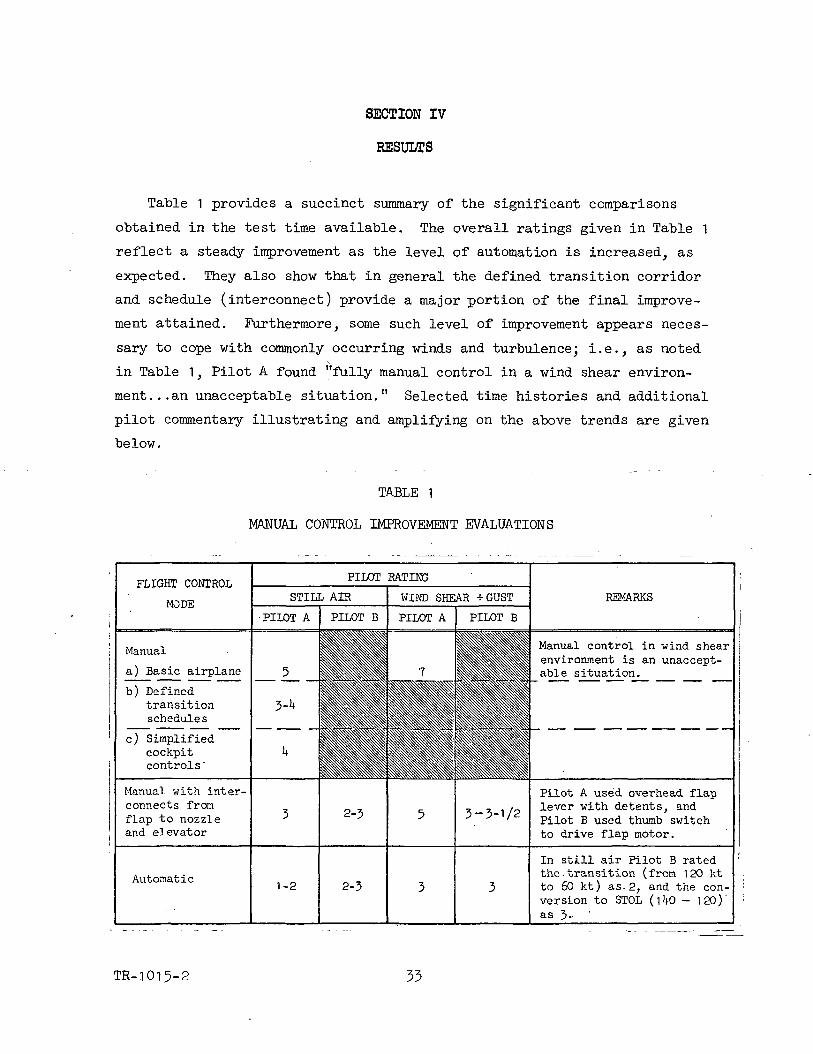
Table 1 provides a succinct summary of the significant comparisons
obtained in the test time available. The overall ratings given in Table 1
reflect a steady improvement as the level of automation is increased, as
expected. They also show that in general the defined transition corridor
and schedule (interconnect) provide a major portion of the final improve-
ment attained. Furthermore, some such level of improvement appears neces-
sary to cope with commonly occurring winds and turbulence; i.e., as noted
in Table 1, Pilot A found "fully manual control in a wind shear environ-
ment... an unacceptable situation." Selected time histories and additional
pilot commentary illustrating and amplifying on the above trends are given
below.
TABLE 1
MANUAL CONTROL IMPROVEMENT EVALUATIONS
FLIGHT CONTROL
MODEREMARKS
Manual
a) Basic airplane
b) Definedtransitionschedule s
c) Simplifiedcockpitcontrols'
Manual control in wind shearenvironment is an unaccept-able situation.
Manual with inter-connects fromflap to nozzleand elevator
Pilot A used overhead flaplever with detents, andPilot B used thumb switchto drive flap motor.
Automatic
In still air Pilot B ratedthe.transition (from 120 ktto 60 kt) as-2, and the con-version to STOL (1 0 - 120)'
as 3-
TR-.1015-2 33

Figure 12 is an example of a typical time history, in this case for a manual
approach utilizing the flap/nozzle schedule in smooth air and also emplpying
the overhead control arrangement. This run was made after considerable practice
and familiarization with the basic interconnect system and automatic modes of
control, so that the pilot had pretty well learned how to fly the airplane.
(in fact as a result of this learning process, Pilot A changed his rating from
a 5 to a 3~^«) It may be seen that the transition maneuver was stopped at 80 kt
and held for a considerable length of time and then continued down to 60 kt
where the glide slope was intercepted through a pitchover attitude change. The
glide slope tracking exhibited is quite good, and as indicated by the fairly
constant 9 trace and the active nozzle trace, it was controlled primarily by use
of the nozzle. In addition, however, the pilot did use throttle, as evidenced
by the hot thrust and throttle position variations shown in the lowermost trace.
This trace also indicates that the hot thrust follows the throttle motion with
reasonable fidelity. (On later figures, there is no by trace but, as shown here,
It bears a close resemblance to the hot thrust trace which is contained in all
(the remaining figures.) It is pointed out that the occasional large "bumps"• . y
in the h trace that seem to occur when no inputs are applied are in fact '
responses to step increments in flap extension. At the end of the run it
may be seen that the flare maneuver was accomplished by pulling up in attitude
and decreasing the nozzle angle to provide more thrust. Notice, as a result,
that the airspeed is quite constant throughout the flare until touchdown.
Notice also that for the entire run the throttle was used quite sparingly
in that the major portions of the run are at nearly constant values of thrust.
Pilot comments follow.
9 The decelerate- stop- decelerate task performed manuallygives too much workload. The task with three controls(&F, 8V, ST) is too much.
• The vehicle is "more fun manually, " but performancecapability is restricted. You cannot go to a desiredspeed easily (manually), and you probably couldn't doit in gusty air. The workload is too high.
e The rating change from a 5 to a 3-^ (noted above) doesn'treflect the smaller head- and tail-wind envelope thatexists with manual control.
TR-1015-2

HO
-Paoo
a
0)
o
-Poo
X!O0)
OJ
tfl
•OJ
0)
I
TR-1015-2
e The nozzle dimdicator should be on the same meter as theflap indicator—and displayed in a way that tells thepilot at a glance when nozzle and flap are correctly"synchronized" and when they are not. Thus, the pilotwould know how to get "back" to the proper nozzle posi-tion for any given flap setting.
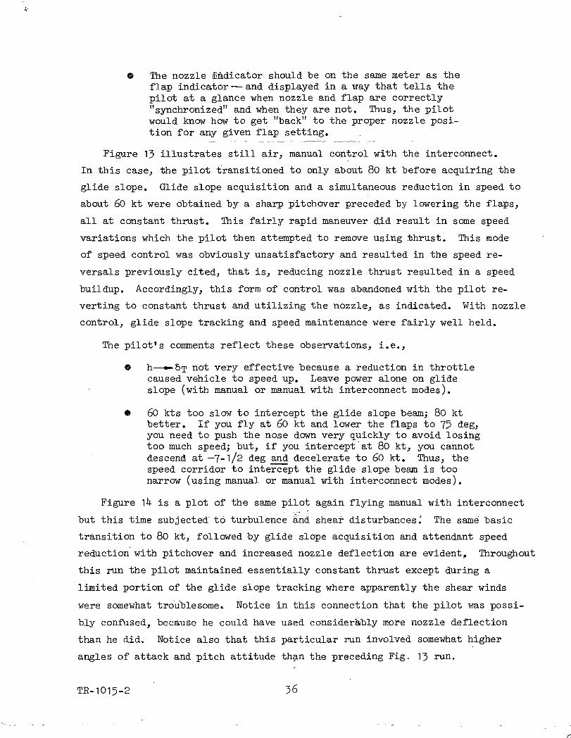
Figure 13 illustrates still air, manual control with the interconnect.
In this case, the pilot transitioned to only about 80 kt before acquiring the
glide slope. Glide slope acquisition and a simultaneous reduction in speed to
about 60 kt were obtained by a sharp pitchover preceded by lowering the flaps,
all at constant thrust. This fairly rapid maneuver did result in some speed
variations which the pilot then attempted to remove using thrust. This mode
of speed control was obviously unsatisfactory and resulted in the speed re-
versals previously cited, that is, reducing nozzle thrust resulted in a speed
buildup. Accordingly, this form of control was abandoned with the pilot re-
verting to constant thrust and utilizing the nozzle, as indicated. With nozzle
control, glide slope tracking and speed maintenance were fairly well held.
The pilot's comments reflect these observations, i.e.,
C h—^-&T not very effective because a reduction in throttlecaused vehicle to speed up. Leave power alone on glideslope (with manual or manual with interconnect modes).
• 60 kts too slow to intercept the glide slope beam; 80 ktbetter. If you fly at 60 kt and lower the flaps to 75 deg,you need to push the nose down very quickly to avoid losingtoo much speed; but, if you intercept at 80 kt, you cannotdescend at —7-1/2 deg and decelerate to 60 kt. Thus, thespeed corridor to intercept the glide slope beam is toonarrow (using manual or manual with interconnect modes).
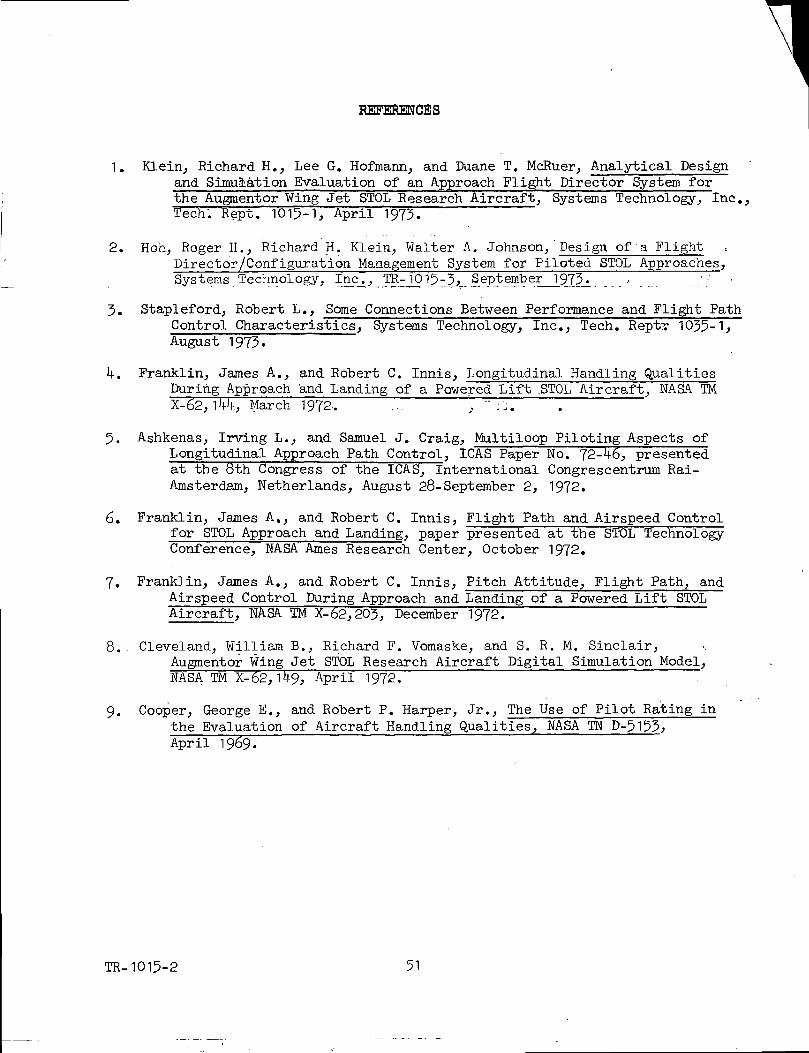
Figure 1^ is a plot of the same pilot again flying manual with interconnect
but this time subjected to turbulence and shear disturbances.' The same basic
transition to 80 kt, followed by glide slope acquisition and attendant speed
reduction with pitchover and increased nozzle deflection are evident, Throughout
this run the pilot maintained essentially constant thrust except during a
limited portion of the glide slope tracking where apparently the shear winds
were somewhat troublesome. Notice in this connection that the pilot was possi-
bly confused, because he could have used considerably more nozzle deflection
than he did. Notice also that this particular run involved somewhat higher
angles of attack and pitch attitude than the preceding Fig. 13 run.
TR-1015-2 36

I I-.-.
O
-PCO
0)rHO(Q
§O
•H-P03
-PO0)C
§. O
-Pfl
-p•H
i-l03g03
<Ufcpf(30
•H
TR-1015-2

•8
OO
(Ur-loCd
GOO
03Q>
0)Oaa;
-po0)
I.aha>-p
-p•H
TR-1015-2

Additional general Pilot A commentary on the manual and manual with inter-
connect mode follows:
• On the 7-1/2 deg glide slope there is not sufficientdescent capability with nozzle (only about an additional400 ft per min). But get even less descent capabilitywith less than 75 deg flap.
O Doesn't like the button flap control because there arean infinite number of flap positions possible; and doesn'tlike to have to look at the flap gauge. He wants onlya few possible flap positions. Thus, he likes the over-head flap lever that has detented positions better.
9 Summarizing the manual with interconnect mode^ it iseasy to decelerate and intercept the glide slope, but7 control on glide slope is poor. It is, however, animprovement over purely manual control.
Figure 15 represents a run similar to the last except that it was conducted
by Pilot B rather than Pilot A. In this case, the transition to 60 kt is com-
pleted before the glide slope is acquired. The nozzle thrust is held constant
throughout the entire maneuver. The glide slope, as before, is acquired with
a pitchover and a nozzle angle increase. Nozzle control-.of the glide slope
is evident, but it is only fair, in that a low-frequency eGg oscillation is•
evident. Notice that a, e, and h perturbations are somewhat lower than those
of the preceding run.
Figure 16 is essentially a duplication of the preceding figures except that
in this case overhead flap control was utilized rather than the flap button
on the console. The runs are quite similar except that Fig. 16 indicates a
little more nozzle activity during the transition and glide slope tracking
portions of the flight. Glide slope tracking, on the whole, appears also to
be a little more consistent than in the previous trial.
The following pilot commentary is applicable to Figures 15 and 16:
O With the flap on the thumb button he could hold attitudebetter (no large transients). Prefers button to detentcontrol.
• A better technique to use when acquiring the glide slopebeam is to fly at 70 kt (instead of 60) until ready tostart descending. Then put down 75 deg of flaps (from55 deg) and push over as vehicle slows down to 60 kt.In this way you don't need to push over so quickly, andthe maneuver is no longer critical.
TR-1015-2 -39

O o
8
I - ° E
— " I? *-*
^
1 1 II 1
in O m co —^ o
(75 g « o* 15 — *w t o .g o ° c
C
= 1*~"
I 1
°8
i"»I?
1 --sl>= asa3 ~ 0-5
i ii iO O <n o
« OJ
S ° "s § «>I'S 2 £(§"
51
1
cvjo '
• 1o»O)
cV 0
5 0^a
1 tm oOJ
o £*- O0 '*- <
is"
, g,s
imCVJ
u^1
» -o
pq-po-1-1•HCM
OO
• s -OP
cd0)
0)oC!
0)
po
§o
-pH
•P•Hisr-l05
g
Q)
TR-1015-2

03
O
050)
Q)o pqid0) -pr-l O3 r-\£> -H^ PL,
^ O<U fnTi -Po a
-pO ft0) 03(3 rH
o ^-h tJ0) Q)-P -PC C
M <U
x: a;-P Q
033a
VQ
in O incvi — OQ O o in inw w
o " =-•ifo •* .—„ ° o>
.2? O O 0)
?? 2
£§ -O — in O>
Is-'*ua.
TR-1015-2

Figure 17 also shows the manual control with interconnect using the detented
flap. In this case, however, the task was simply to stop, the transition and
return to level flight at 1*4-0 kt (deceleration-acceleration). The transition
was stopped at 80 kt and the entire maneuver was accomplished with nozzle
thrust held constant. There is little evidence here that the pilot attempted•
to control h deviations with the nozzle. Rather, it seems he was using 6 to
control h. Of course, for the minimum speed shown (80 kt), such a technique
is feasible because the aircraft is still (barely) on the front side of the
jdrag curve.
Figure 18 is a record of glide slope control with the automatic mode but
without an inner-loop SAS operating. In this case, the pilot attempted to
control on the glide slope with throttle, as evident by the lowermost nozzle
thrust trace. Notice that now the airspeed variations are not particularly
troublesome despite the use of thrust because of the speed-holding features
of the automatic mode.
Figure 19 is a run similar to the preceding except that the pilot here is
using attitude (through elevator) to control glide slope rather than throttle.
(Nozzle thrust was held constant.) In general, this mode of control resulted•
in smaller a, nz, V, and h perturbations than did use of the throttle. A further
point of interest in comparing these two figures is the fact that the attitude
time histories look quite similar to the nozzle thrust time histories in Fig.
18, that is, to maintain glide slope appears to require similar kinds of input
timing. In fact, these two figures demonstrate that with the automatic system
the pilot has a choice of primary control and that he can use either throttle
or attitude to regulate glide slope deviations.
The pilot commented that he
• Likes (and uses) h—^-&e on glide slope with the speed-command system. It makes it a nice flying airplane evenwithout the SAS.
Figure 20 is an example of the fully automatic mode, in this case as
utilized"'in a decelerating, stopping, accelerating, transition maneuver. The
first, short, stop at about 105 kt is not as clean.as it might be, apparently'
because the nozzle thrust had not yet been set at its proper value, as evidenced
in the lower trace. However, once set at a constant value, the remaining
TR-1015-2 *4-2

I ICM —
T3 O
O mw cvi
in mCM N
o mCMi
o -«o> .• o
O £
o '-^
UJ O.
r-)
0)
0)-p0)
0>CJ .
S
-p.2w "£s
-p .<_H U.C °5•P f-iTH <u? (UrH O03 0)
c~-
<u
•Hf*
TR-1015-2

Hi 5h 1000
6"*S*- Altitude 5oo|3e oiopeErrorf f* r*
(cleg)Lo 5 -
c.Load
Factornz I
(g's)0
30Angle ofAttack n
a u
(deg)-20
PitchRate
q(deg/sec)
-12.525 h
E leva tor NozzlePocitinn PoSltiOlPosition
Se
(deg)-25
- Off Scale
( f t )
Rate of
12.5-Pitch
Attitude
6(deg)
IMU^^IC
Position
*v(deg)
10,000 (1 3Hot
(UEnS;, 5-°°°(Ibs)
0
Figu]re 18
TR-1015-2
^^
. Automatic Mode, No SAS, Turbulence andControl with Throttle, Pilot B
zzle,;T;:hrus|.M I I:
and Shear, Glide Slope

1m
if
io
Q.£ »_ "^(f) O </) O>
t o oO UJ VW T3!5 —
1 1 1
m oj —o
•o oO ^~ M
5 o c
1 10 C
r
*w~
C7>
1
D O0
*4—0 ^ ">0} JJ „ O>i i U Cj Q^
O> Jl T3
iOC\J
1
imcvi
1
-C
^^
(X
IO
0)__ CT
cr
imcvi
— ~ ~§^^o>(U•o
1mCVJ
>_o0
(U
UJ
1O
c0
• v>>
oQ_
1
CVJ1
it O>r o3
0)
CO
OJ
f-t03
PQ
CQJ
-p• -H
& *
" -P'ri s
TR-1015-2

decelerating, stop, accelerating maneuvers are accomplished quite smoothly at
almost constant attitude and angle of attack, as indicated. Notice that the
minimum speed is slightly below a commanded speed of 60 kt, but that the error
is apparently smaller than indicated by the previously discusse.d^linear analysis,
Figure 21 is a more complete example of the automatic mode operation in
that it also includes glide slope acquisition and tracking (however, all in
still air); In this case, the decelerate, stop, accelerate, etc., maneuver is
very smoothly performed and essentially at constant nozzle thrust. Glide slope
acquisition and subsequent tracking are both very smooth and steady.
Figure 22 illustrates the performance attained in the automatic mode with
turbulence and shear disturbances. The small perturbations in a and airspeed
are notable as is the rapidity and precision of the transition maneuver.
Summary comments on the automatic mode are as follows:
A The pilots liked the vehicle when it flew "like an airplane."
e The Vc bug should be on the IAS meter (rather than on aseparate meter—an expedience dictated by lack of a con-trollable bug on the IAS meter).
P Pilot A said the speed command mode reduced the workloadconsiderably. But he would rather not have a slewing
; switch on Vc.
ft He liked the idea of speed changing a little when hechanged 7 by moderate amounts. (This was with a gainof 5 deg/kt instead of 10.on the speed error signal.)
• Pilot A liked the automatic mode very much because itgave him good 7 control on glide slope with eitherthrottle or attitude. He said "it flies like a realstable airplane."
• Pilot B things the speed command system is tremendous.
TR-1015-2

ooo
o -Qo> E._,
IC
Ooo
c~E
Oro
OCO
TJ0)0) ^
8->S
Oro
m o m o m o1 — — ojOr-
o oOJ O
oo
ooom
0>T3
O 0>~ 03 O)±: "o
^> oN '•*-
o>c 1^li I o
-p•a•H
rH
-
„ o<u o
o
03
O. OJ
o QOJ
0)
I I I I I Iin inOJ CM
_L_oOJ — O O
roO iQOJ OJ
oQ)
.
o o c o>_,o ._^ o a <u .-to D-
a>T3 LUQ.
mOJ
a>
TR-1015-2

P)Q)-PCO
•H(3-PCO
-PO
•H<
i-H•H-P
Q)
OHCO
0? 0)
O•H O-P -P03£-" <~1O O-P -H3 -P< -H
• cfi<- ^OJ EH
(U
TR-1015-2

PQ
H•HP-i
03 '01
0)u
I
Q)••dO
o•H-P
1I
CMCM
>o O>»0 CO
O (O
5-1 ,-5 *«.?-=
to o in oj — o ( 8 mrJin o in <n o
;£„»o -— *> s*s««
TR-1015-2

SECTION V
CONCLUSIONS
The basic conclusions, supported by both analysis and simulation, are:
c A four.-control (&e.j &F, &v, &T) manual situation resultsin excessive pilot workload.
o The concept of using control crossfeeds to constrain thepossible vehicle configurations (as well as to simplifythe piloting task) was confirmed as useful and desirable.It is especially effective when used also to eliminaterelatively unsafe configurations and improve operationalperformance (e.g., it is noted that throughout the tran-sition there.are adequate margins in angle of attack,throttle, and nozzle available for maneuvering the air-craft should the need arise).
© The automatic system was validated as being very desirable.It made the vehicle "fly like an airplane," and made iteasy to control flight path with either attitude or throttle.
/Additional, incidental findings specific to the Augmentor Wing aircraft
configuration are listed below.
© -E.br standardization, the cockpit controls should be moveddown to the center console.
9 Acceleration/deceleration should be accomplished via thenozzle during transition. '
• When nozzle is crossfed from flap, then the nozzle indi-cator gauge should be part of the flap gauge so that thepilot can tell at a glance what the appropriate trim nozzleposition should be.
® For the automatic system, the commanded speed should bedisplayed on the IAS meter.
TR-1015-2 50
REFERENCES
1. Klein, Richard H., Lee G. Hofmann, and Duane T. McRuer, Analytical Designand Simulation Evaluation of an Approach Flight Director System forthe Augmentor Wing Jet STOL Research Aircraft, Systems Technology, Inc.,Tech". Kept. 1015-1, April 1973.
2. Hoh, Roger H., Richard H. Klein, Walter A. Johnson,'Design of a FlightDirector/Configuration Management System for Piloted STOL Approaches,Systems Technology, Inc., TR-1015-3, September 1973. , '_:"...-
3. Stapleford, Robert L., Some Connections Between Performance and Flight PathControl Characteristics, Systems Technology, Inc., Tech. Rept? 1035-1;August 1973.
14-. Franklin, James A., and Robert C. Innis, Longitudinal Handling QualitiesDuring Approach and Landing of a Powered Lift .STOL Aircraft, NASA TMX-62, 1MI, March 1972-. ~ ,, ~ :j. i
5. Ashkenas, Irving L., and Samuel J. Craig, Maltiloop Piloting Aspects ofLongitudinal Approach Path Control, ICAS Paper No. 72-46, presentedat the 8th Congress of the ICAS, International Congrescentrum Rai-Amsterdam, Netherlands, August 28-September 2, 1972.
6. Franklin, James A., and Robert C. Innis, Flight Path and Airspeed Controlfor STOL Approach and Landing, paper presented at the STOL TechnologyConference, NASA Ames Research Center, October 1972.
7. Franklin, James A., and Robert C. Innis, Pitch Attitude, Flight Path, andAirspeed Control During Approach and Landing of a Powered Lift STOLAircraft, NASA TM X-62,203, December 1972.
8. Cleveland, William B., Richard F. Vomaske, and S. R. M. Sinclair, •;Augmentor Wing Jet STOL Research Aircraft Digital Simulation Model,NASA TM X-62,1 9, April 1972. "
9. Cooper, George E., and Robert P. Harper, Jr., The Use of Pilot Rating inthe Evaluation of Aircraft Handling Qualities, NASA TN D-April 1969.
TR-1015-2 51