a/v control center - berner's site · blades with one wider than the other. a grounding type...
TRANSCRIPT

MX119Owner’s Manual
McIntosh Laboratory, Inc. 2 Chambers Street Binghamton, New York 13903-2699 Phone: 607-723-3512 FAX: 607-724-0549
A/V Control Center
Manufactured under license from Dolby Laboratories. “Dolby”, “Pro Logic” and the double-D symbol are trademarks of Dolby Laboratories.
“DTS” and “DTS Digital Surround” are registered trademarks of Digital Theater Systems, Inc.

2
IMPORTANT SAFETYINSTRUCTIONS!
PLEASE READ THEM BEFOREOPERATING THIS EQUIPMENT.
WARNING - TO REDUCE RISK OFFIRE OR ELECTRICAL SHOCK, DONOT EXPOSE THIS EQUIPMENT TO
RAIN OR MOISTURE.
The lightning flash with arrowhead,within an equilateral triangle, is intendedto alert the user to the presence ofuninsulated “dangerous voltage” withinthe product’s enclosure that may be ofsufficient magnitude to constitute a riskof electric shock to persons.
NO USER-SERVICEABLE PARTSINSIDE. REFER SERVICING TO
QUALIFIED PERSONNEL.To prevent the risk of electric shock, do not remove cover or
back. No user-serviceable parts inside.
The exclamation point within an equi-lateral triangle is intended to alert theuser to the presence of importantoperating and maintenance (servic-ing) instructions in the literature ac-companying the appliance.
1. Read these instructions.2. Keep these instructions.3. Heed all warnings.4. Follow all instructions.5. Do not use this apparatus near water.6. Clean only with a dry cloth.7. Do not block any ventilation openings. Install in
accordance with the manufacturer’s instructions.8. Do not install near any heat sources such as
radiators, heat registers, stoves, or otherapparatus (including amplifiers) that produceheat.
9. Do not defeat the safety purpose of the polarizedor grounding-type plug. A polarized plug has twoblades with one wider than the other. A groundingtype plug has two blades and a third groundingprong. The wide blade or the third prong areprovided for your safety. If the provided plugdoes not fit into your outlet, consult an electricianfor replacement of the obsolete outlet.
10. Protect the power cord from being walked on orpinched particularly at plugs, conveniencereceptacles, and the point where they exit fromthe apparatus.
11. Only use attachments/accessories specified by themanufacturer.
12. Use only with the cart, stand, tripod, bracket, ortable specified by the manufacturer,or sold with the apparatus. When acart is used, use caution when movingthe cart/apparatus combination toavoid injury from tip-over.
13. Unplug this apparatus during lightning storms orwhen unused for long periods of time.
14. Refer all servicing to qualified service personnel.Servicing is required when the apparatus hasbeen damaged in any way, such as power-supplycord or plug is damaged, liquid has been spilledor objects have fallen into the apparatus, theapparatus has been exposed to rain or moisture,does not operate normally, or has been dropped.
15. Do not expose this equipment to dripping orsplashing and ensure that no objects filled withliquids, such as vases, are placed on theequipment.
16. To completely disconnect this equipment fromthe a.c. mains, disconnect the power supply cordplug from the a.c. receptacle.
17. The mains plug of the power supply cord shallremain readily operable.

3
If an outside antenna or cable system is connected tothe product, be sure the antenna or cable system isgrounded so as to provide some protection againstvoltage surges and built-up static charge. Article 810of the National Electrical Code, ANSI/NFPA 70, pro-vides information with reguards to proper groundingof the mast and supporting structure, grounding of thelead-in wire to an antenna discharge unit, and size ofground conductors, location of antenna-discharge unit,connection to ground electrodes and requirements forthe grounding electrode.
Outdoor Antenna Grounding
Example of antenna grounding as perNational Electrical Code, ANSI/NFPA 70
Safety Instructions

4
Safety Instructions ............................................................. 2Thank You and Please Take a Moment .............................. 4Technical Assistance and Customer Service ..................... 4Table of Contents ............................................................... 4Important Information ....................................................... 5Connector Information ...................................................... 6Introduction ....................................................................... 7Performance Features ........................................................ 7Dimensions ........................................................................ 8Installation ......................................................................... 9ConnectionsRear Panel Multizone, Control and Switch ..................... 10Rear Panel Analog and Digital Audio Connections ........ 11Rear Panel Video Connections ........................................ 12How to Connect Multizone, Data and Power Control ..... 13How to Connect Digital Audio Components ................... 14How to Connect Analog Audio Componentsfor five or six channels .................................................... 15How to Connect Analog Audio Componentsfor seven channels ........................................................... 16How to Connect Video Components ............................... 18How to Connect for Zone B ............................................ 19Front Panel FeaturesFront Panel Controls and Sensor ..................................... 20Front Panel Push-button and Switch ............................... 21Front Panel Displays ........................................................ 22Remote ControlRemote Control Push-Buttons ......................................... 24How to Operate by Remote Control ................................ 25Setup ModeHow to Operate the Setup Mode ..................................... 26Default Settings ............................................................... 27How to Adjust for Loudspeaker Size ............................... 28How to Adjust Loudspeaker Time Delay ........................ 30How to Adjust Loudspeaker Levels ................................ 31How to Change the Input Setup ....................................... 33How to Change the Volume Setup ................................... 38How to Change the Advanced Settings ........................... 39OperationHow to Operate the MX119 ............................................ 41How to Operate the Trim Mode....................................... 44How to Operate the Surround Mode ............................... 47How to Make a Recording ............................................... 49How to Operate Zone B ................................................... 50Additional InformationAudio and General Specifications ................................... 51TM1 AM/FM Tuner ModuleTM1 Table of Contents .................................................... 52Packing Instructions ........................................................ 59
Table of ContentsYour decision to own this McIntosh MX119 A/V ControlCenter ranks you at the very top among discriminating mu-sic listeners. You now have “The Best.” The McIntoshdedication to “Quality,” is assurance that you will receivemany years of musical enjoyment from this unit.
Please take a short time to read the information in thismanual. We want you to be as familiar as possible with allthe features and functions of your new McIntosh.
Customer Service
Technical Assistance
Please Take A Moment
Thank You
Copyright 2004 © by McIntosh Laboratory, Inc.
The serial number, purchase date and McIntosh Dealername are important to you for possible insurance claim orfuture service. The spaces below have been provided foryou to record that information:
Serial Number:Purchase Date:Dealer Name:
If it is determined that your McIntosh product is in need ofrepair, you can return it to your Dealer. You can also returnit to the McIntosh Laboratory Service Department. For as-sistance on factory repair return procedure, contact theMcIntosh Service Department at:
McIntosh Laboratory, Inc.2 Chambers StreetBinghamton, New York 13903Phone: 607-723-3515Fax: 607-723-1917
If at any time you have questions about your McIntoshproduct, contact your McIntosh Dealer who is familiar withyour McIntosh equipment and any other brands that maybe part of your system. If you or your Dealer wish addi-tional help concerning a suspected problem, you can re-ceive technical assistance for all McIntosh products at:
McIntosh Laboratory, Inc.2 Chambers StreetBinghamton, New York 13903Phone: 607-723-1545Fax: 607-723-3636

5
Important Information
1. The MX119 A/V Control Center has provisions for adding anoptional McIntosh TM1 AM/FM Tuner Module for RadioStation Reception. The TM1 is available from your McIntoshDealer and can be installed at any time, usually while youwait. Refer to page 52 for additional TM1 information.
2. Before making any connections to the MX119, make sure theMain POWER Switch is in the Off position. Failure to do socould result in malfunctioning of some or all of the system’snormal operations.
3. All Zones in a McIntosh Multizone System (except for Zone A)are unbalanced Analog Audio Signals only. The Digital AudioInput Source Signals and Balanced Analog Audio InputSignals will not appear at any of the Zones (including Zone Bof the MX119 and Zones of a CR12 or CR16 when connectedto the MX119). The Source Component Unbalanced AnalogOutputs must be connected to the MX119.
4. The connection of a turntable to the PH/AUX Input jacksrequires changes to be made in the SETUP Mode, refer topage 33. The MX119 INPUT Control for Zone A and B needsto be placed in the PHON position in order to make arecording from the turntable and/or for listening to a record inZone B of the MX119 or the Zone(s) of a CR16 whenconnected to the MX119.
5. Connecting Cables are available from the McIntosh PartsDepartment:
Data and Power Control Cable Part No. 170-202Six foot, shielded 2 conductor, with 1/8 inch stereo miniphone plugs on each end.
Control Center to Multi-Channel Power Amplifier CablePart No. 170-631
Six foot, DB25, shielded, straight through, 25 conductormale-to-female cable.
Control Center to CR16 Cable Part No. 170-430Six foot, DB37, shielded, straight through, 37 conductormale-to-male cable.
6. When the MX119 is connected to some McIntosh MultichannelPower Amplifiers with a 25 conductor cable, the amplifiermeters may automatically indicate the output of individualchannels during the Speaker Level Setup Operation. Refer tothe Power Amplifiers Owner’s Manual for additionalinformation.
7. When the MX119 is connected to a CR16 Controller Input Bjack with the 37 conductor cable, do not connect a 25conductor cable to the CR16 Controller Input A jack fromanother McIntosh Control Center.
8. When the MX119 is connected with a CR16, the MX119provides fixed specific audio signals that match the CR16Inputs. If the MX119 Inputs listed below are re-titled, theInputs Titles on the CR16 will no longer match. For example,if the MX119 TV Input (4), is reassigned as DVD2, selectingthe TV Input on the CR16 will receive the audio signals fromDVD2.
MX119 Inputs CR16 Inputs MX119 Inputs CR16 Inputs 0. TUNER TUNER 2. CD (2) CD2 1. PH/AUX AUX 3. SAT LV
Important InformationMX119 Inputs CR16 Inputs MX119 Inputs CR16 Inputs 4. TV TV 6. VCR 1 VCR 1 5. DVD DVD 7. TAPE 1 TAPE 1
9. The MX119 Input Source Name “DVD” is equivalent to “V-Aux” on some McIntosh Keypads, Remote Controls andAudio/Video Control Centers.
10. Up to four McIntosh Sensors or Keypads can be wired inparallel for both Zones A and B.
11. When a McIntosh WK-2 Keypad or a R649 Sensor is to beconnected to the McIntosh MX119 A/V Control Center thatuses a RJ-45 Connector Plug instead of the “F” CoaxialConnector, connect the Center Conductor to Pin 1 and theShield Conductor to Pin 2. Refer to the figure below.
12. The Zone A and Zone B IR Inputs, with 1/8 inch mini phonejacks, are configured for non-McIntosh IR sensors such as aXantech Model 291-10. To avoid possible interaction,disable the MX119 Front Panel Sensor with the switchrecessed in the bottom panel behind and to the left of theSensor.
13. System Setup operations must be performed in the orderthey appear in the Main System Setup Menu as they areinteractive.
14. In order to hear bass frequencies below 80Hz, your systemmust include either a Subwoofer or Large FrontLoudspeakers.
15. When an assigned Digital Input and a matching AnalogInput are in use, the MX119 automatically searches first fora Digital Signal. If no Digital Signal is sensed, it switches tothe Analog Input.
16. Certain DVD or Laser Video Disc Players that arereproducing Digital DTS Signals into a MX119 DigitalInput, may only produce noise from their Analog Outputs. IfZone B is turned on and that same input is selected, thatnoise will be heard.
17. There are three types of Video Signals that can be connectedto and selected by the MX119; Composite, S-Video andComponent. Zone A, Zone B and RECord Outputs have bothComposite and S-Video connections; the Component VideoOutput is for Zone A only. The MX119 has Digital VideoProcessing Circuitry that will Up-Convert the desiredComposite Input to S-Video; it will also Up-Convert thedesired Composite and/or S-Video Inputs to ComponentVideo.
18. For additional connection information, refer to the owner’smanual(s) for any component(s) connected to the MX119A/V Control Center.
RJ-45Plug
Data Ground(to Pin 2)
Shielded Cable Data Signal(to Pin 1)
“F” Connector
Pin 1 Pin 8

6
Connector InformationKeypad Terminal ConnectorTo use a WK-3 or WK-4 Keypad with the MX119, connectthe shield and four leads of a shielded 4 conductor cable toa RJ-45 Connector Plug, according to the numbers listedbelow. There is a numbered connector built into each Key-pad, which has a different pin out.
MX119 RJ-45 WK-3 and WK-4 Keypad1. Signal Data 1. Supply Voltage Positive2. Signal Data Gnd. 2. Supply Voltage Negative
and Cable Shield 3. Cable Shield3. N/C 4. Signal Data4. Supply Voltage Negative 5. Signal Data Gnd.5. Supply Voltage Positive6. N/C7. N/C8. N/C
RS232 DB9 Connector Pin Layout1. N/C 6. N/C2. Data Out (TXD) 7. N/C3. Data In (RXD) 8. N/C4. N/C 9. N/C5. Gnd.
Multi-Channel Amp DB25 Connector Pin Layout 1. Left Front + 15. Center Front Gnd. 2. Center Front + 16. Right Front Gnd. 3. Right Front + 17. Subwoofer Gnd. 4. Subwoofer + 18. Left Surround Gnd. 5. Left Surround + 19. Right Surround Gnd. 6. Right Surround + 20. Left Back Surround Gnd. 7. Left Back Surround + 21. Right Back Surround Gnd. 8. Right Back Surround + 22. N/C 9. N/C 23. N/C10. N/C 24. System Calibrate Gnd.11. N/C. 25. Power Control Gnd.12. System Calibrate13. Power Control In14. Left Front Gnd.
XLR ConnectorsBelow is the Pin configuration for the XLR Balanced Inputand Output Connectors on the MX119. Refer to the dia-gram for connection:
PIN 1: Shield/GroundPIN 2: + SignalPIN 3: - Signal
Multizone Controller (DB37 Connector):1. Accessory-On 14. SAT-Left 26. CD-Data2. SYS-Off 15. TV-Left 27. N/C3. Sum Data 16. Aux-Left 28. N/C4. DVD-Data 17. Tape 1-Left 29. Ground5. SAT-Data 18. Tuner-Left 30. DVD-Right6. Aux-Data 19. CD-Left 31. VCR 1-Right7. Tuner-Data 20. Video Power 32. SAT-Right8. N/C 21. Ground 33. TV-Right9. N/C 22. Home-Data 34. Aux-Right
10. N/C 23. VCR 1-Data 35. Tape 1-Right11. Ground 24. TV-Data 36. Tuner-Right12. DVD-Left 25. Tape 1-Data 37. CD-Right13. VCR 1-Left
Power Control ConnectorThe MX119’s Power Control Outputs provide a 5 volt sig-nal. Use a 1/8 inch stereo miniphone plug to connect to the PowerControl Input on other McIntoshComponents.
Data and IR Input Port ConnectorsThe MX119’s Data Port Output provides Remote ControlSignals. Use a 1/8 inch stereo mini phone plug to connectto the Data Port Inputs on McIntosh Source Units. The IRPorts also use a 1/8 inch stereo mini phone plug and allowsthe connection of other brands IR Sensors to the MX119.
Connector Information
MX119KeypadSocket
Positive
N/C
Negative
Pin 1Pin 2
Pin 3
Data PortConnector Data Signal
N/C
Ground
IR Input PortConnector Data Signal
Ground
N/C

7
Performance Features
Introduction
••••• Balanced Inputs and OutputsA pair of Balanced high level Inputs (assignable) and FrontLeft, Center and Right Channel Balanced Outputs are pro-vided.
••••• Moving Magnet Phono InputThere is a Precision Phono Preamplifier for Moving Mag-net Cartridges.
••••• On-Screen and Multifunction Fluorescent DisplaysA comprehensive On-Screen Display capability makes iteasy to perform setup adjustments using the Remote Con-trol. The front panel display indicates volume levels, tunerfunctions, input selection, operating mode and setup func-tions.
••••• Automatic Mode Switching with Auto MemoryThe MX119 Automatically Switches Operating Modes ac-cording to the input signal. Zone A will memorize the Pre-ferred Mode settings last used for each input.
••••• Separate Listen and Record Input SelectionThe 6 Analog Audio/Video and 2 Analog Audio only Inputscan be retitled for any desired signal sources. Any unusedinput can be “turned off” so the input selector will skipover it. The six Digital Inputs can be assigned to any of theZone A Inputs. Separate Record and Listen Circuits allowrecording of one program source while listening to another.
••••• Latest in Digital Audio ProcessingThe MX119 incorporates the latest technology in digitalmulti-channel processing, including Dolby Digital EX, ProLogic IIx, DTS-ES and NEO:6.
••••• LED Signal Format IndicatorsThe MX119 includes eight LEDs on the front panel to indi-cate what type of signal processing is chosen.
Introduction and Performance Features
Now you can take advantage of traditional McIntosh stan-dards of excellence in the MX119 A/V Control Center asthe heart of your Home Theater System. The MX119 pro-vides superior eight channel reproduction with the latest indigital decoding combined with complete audio and videoswitching. The McIntosh MX119 sets new standards foraccuracy in a Home Theater System.
••••• Pure Stereo ModeWhen the Stereo Mode of Operation is selected for an ana-log source the signal is amplified with no digital processingplaced in the signal path.
••••• Adjustable Channel Level and Time DelayA built-in test signal generator allows all eight channels tobe calibrated for precise volume levels with either auto-matic or manual channel switching and can be adjusted fortime delay to compensate for different distances from eachLoudspeaker to the listening area.
••••• Digitally Controlled Volume and Tone ControlsA Precision Tracking Volume Control adjusts all eightchannels with tracking accuracy better than 0.5dB. Digi-tally controlled bass, treble and loudness analog circuitsprovide a wide range of tone shaping with no loss in tradi-tional McIntosh sonic excellence.
••••• Video Switching with Digital Video ProcessingAny Composite and/or S-Video Input can be Up-Convertedto a Component Video Signal with the built-in DigitalVideo Processing Circuitry. There is also video switchingfor all three types of video signals.
••••• External Eight Channel InputAn external eight channel signal processor can be con-nected to these inputs as well as a DVD-Audio Player orSuper Audio Disc Player with a built-in processor.
••••• Dual Zone and Additional ExpansionThe MX119 has the built-in ability to control a separateremote audio/video zone with program selection indepen-dent of Zone A, using a dedicated power amplifier andspeakers. A rear panel connector is provided to interfacewith the CR16 Remote Control System to add four addi-tional Remote A/V Zones.
••••• Fiber Optic Solid State Front Panel IlluminationThe Illumination of the Front Panel is accomplished by thecombination of custom designed Fiber Optic Light Diffus-ers and Light Emitting Diodes (LEDs). This provides uni-form Front Panel Illumination, together with the extra longlife of the LEDs.
••••• Glass Front PanelThe famous McIntosh Illuminated Glass Front Panel en-sures the pristine beauty of the MX119 will be retained formany years.

8
Dimensions
The following dimensions can assist in determining thebest location for your MX119. There is additional informa-tion on the next page pertaining to installing the MX119into cabinets.
Dimensions
17-1/2"44.45cm
6-5/16"16.03cm
7-5/8"19.37cm
18-1/2"46.99cm
3/16"0.48cm
13-1/4"33.66cm
17"43.18cm
Front View of the MX119
Rear View of the MX119
Side View of the MX119
7-1/8"18.10cm
13/16"2.06cm
6-1/2"16.51cm
14-1/16"35.72cm
17"43.18cm
7/8"2.22cm

9
Installation
InstallationThe MX119 can be placed upright on a table or shelf,standing on its four feet. It also can be custom installed in apiece of furniture or cabinet of your choice. The four feetmay be removed from the bottom of the MX119 when it iscustom installed as outlined below. The four feet togetherwith the mounting screws should be retained for possiblefuture use if the MX119 is removed from the custom instal-lation and used freestanding. The re-quired panel cutout,ventilation cutout andunit dimensions areshown.
Always provideadequate ventilationfor your MX119.Cool operation en-sures the longest pos-sible operating life forany electronic instru-ment. Do not installthe MX119 directlyabove a heat generat-ing component suchas a high poweredamplifier. If all thecomponents are in-stalled in a singlecabinet, a quiet run-ning ventilation fancan be a definite assetin maintaining all thesystem components atthe coolest possibleoperating tempera-ture.
A custom cabinetinstallation shouldprovide the followingminimum spacing di-mensions for cool op-eration. Allow at least2 inches (5.08cm)above the top, 2inches (5.08cm) be-low the bottom and 1
6-5/8"16.83cm
17-1/16"43.34cm
Cutout Opening for Custom Mounting
MX119 Front Panel Custom Cabinet Cutout
CutoutOpening
forVentilation
Cutout Opening for VentilationSupportShelf
CabinetFrontPanel
ChassisSpacers
MX119 Side Viewin Custom Cabinet
MX119 Bottom Viewin Custom Cabinet
13" 33.02cm
13" 33.02cm
15" 38.10cm
1" 2.54cm
14-1/4" 36.20cm
10-7/8" 27.64cm
Notes: Center the Cutout Horitzonally on unit. For purposes of clarity, the above illustration is not drawn to scale.
inch (2.54cm) on each side of the A/V Control Center, sothat airflow is not obstructed. Allow 21 inches (53.34cm)depth behind the front panel. Allow 1 inch (2.54cm) infront of the mounting panel for knob clearance. Be sure tocut out a ventilation hole in the mounting shelf accordingto the dimensions in the drawing.

10
Rear Panel Multizone, Control Connections and Switch
Connect the MX119power cord to a liveAC outlet. Refer to in-formation on the backpanel to determine thecorrect voltage
POWER CONTROLA and B send a turnOn/Off signal to aMcIntosh Power Am-plifier for each Zone
ACC sends a turnOn/Off signal toMcIntosh SourceComponents
DATA Ports send sig-nals to compatiblesource components toallow remote controloperation
TO MULTIZONECONTROLLER con-nects to the McIntoshMultizone ControllerInput B
RS232 connectorfor connection to acomputer or othercontrol device
HOME Data Portconnects to theoptional HC-1Home Controller
SUM A Data Port forconnections to otherMcIntosh Compo-nents
IR INPUTSfor Zone A orB externalsensors
KEYPADSZONE A and Bfor a McIntoshKeypad or IRroom sensor
VIDEO sends aturn On/Off sig-nal to McIntoshVideo SourceComponents
SUM Data Port forZones A and B providesconnections to the otherMcIntosh Components
IR POWER On/Off for Zone Aor B externalSensors

11
Rear Panel Audio and Digital Audio Connections
MULTI-CHANNELAMPlifier connectoraccepts a 25 conductorcable that connects allaudio and power con-trol signals to a McIn-tosh Power Amplifier
DIGITAL INPUTS SAT,CD(2) and AUX receivea digital audio signalfrom the Optical Outputof a component
DIGITAL INPUTSTAPE, DVD and TVreceive a digital audiosignal from the Co-axial Output of a com-ponent
The eight channelEXTERNAL IN-PUTS accept audiosignals from a com-ponent or externalprocessor
ZONE A OUTPUTSsend all eight audiochannel signals topower amplifier in-puts
INPUTS for analogaudio signals from aTAPE, VCR 1, DVD,TV, SAT, CD (2), orPHono/AUX compo-nents
RECord OUTPUTSsupply analog audiorecord signals forrecorders
DIGITAL OUTPUTS bothoptical and coaxial, provide adigital audio signal to an ex-ternal digital processor
ZONE A FIXED OUTPUTSsend a fixed line level, twochannel analog signal asselected by the INPUT ZoneA Control
ZONE B OUTPUTSsend a two channelsignal from the ana-log inputs as selectedby the INPUT ZoneB Control
TUNER INput/OUTput allowsfor connecting an external tunerto the MX119 when the optionalTM1 Module is not installed orTuner Audio Output Signalswhen the TM1 is installed in theMX119
ZONE A BALANCED OUTPUTScontain the program signals for Right,Center and Left Front Channels
BALANCED INPUTSfor two channel com-ponent sources

12
Rear Panel Video Connections
INPUTS for Composite Video Signalsfrom a VCR 1, DVD, TV, SAT, CD (2),or PHono/AUX components
OUTPUT MONitor Asends a Composite orS-Video Signal to amonitor/TV located inZone A
OUTPUTS for RECord supplyComposite or S-Video Signalsfor recorders
OUTPUT MONitor Bsends a Composite orS-Video Signal to amonitor/TV located inZone B
COMPONENT INPUTS receiveComponent Video (Y, PR and PB)Signals from three ComponentVideo Sources
COMPONENT OUTPUTS sendComponent Video (Y, PR and PB)Signals to the ZONE A VideoMonitor
Note: If the MX119 A/V System ControlCenter has the TM1 AM/FMTuner Module installed, proceedto page 53 for Rear PanelAntenna Connection Information.
INPUTS for S-Video Signals from aVCR 1, DVD, TV, SAT, CD (2), orPHono/AUX components

13
Home Controller
McIntosh CR16 Multizone Controller
McIntosh Audio/Video Player
How to Connect Multizone, Data and Power Control
IR Sensor
1. Connect a Data Control Cable from the MX119 DVD(Input 5) Data Port to the McIntosh Audio/VideoPlayer Data In Jack.Note: By adding a McIntosh Remote Control Translator to
the MX119, non McIntosh Source Devices such as aSatellite Receiver can be remotely controlled using aMcIntosh Remote Control and Keypads.
2. Connect a Data Control Cable from the MX119 HOMEData Port to the Home Controller Data In Jack.
3. Connect a 4 conductor shielded cable from the MX119ZONE A KEYPAD Socket to a McIntosh WK-4 Key-pad.
4. Connect a DB37 Cable, shielded straight through 37
How to Connect Multizone, Data and PowerControl conductor, from the MX119 TO MULTIZONE CON-
TROLLER Connector to the CR16 Multizone “Con-troller Input B” socket.
5. Connect a Power Control Cable from the MX119POWER CONTROL ACC Jack to the McIntosh Au-dio/Video Player Power Control In Jack.
6. Connect a Power Control Cable from the MX119POWER CONTROL A Jack to the McIntosh PoweredSubwoofer Power Control In Jack.
7. Connect a Power Control Cable from the McIntoshPowered Subwoofer Power Control Out Jack to theMcIntosh Power Control AC Outlet Strip Power Con-trol Jack.
8. Optionally, connect a Data Control Cable from theMX119 IR INPUTS A to an external IR Sensor.
McIntosh WK-4 Keypad
McIntoshPowerControl
McIntosh Powered Subwoofer

14
Satellite Receiver
How to Connect Digital Audio Components
How to Connect Digital Audio Components1. Connect a cable from the MX119 DIGITAL CO-
AXIAL DVD INPUT (Input E) to the McIntosh Co-axial Digital Output of the McIntosh Audio/VideoPlayer.
2. Connect a cable from the MX119 SAT INPUT (InputC) OPTICAL DIGITAL INPUT to the Optical DigitalOutput of a Satellite Receiver.
3. Connect a cable from the MX119 AUX INPUT (InputA) OPTICAL DIGITAL INPUT to the Optical DigitalOutput of a Digital Audio Recorder.
4. Connect a cable from the Digital Audio Recorder Inputto the MX119 OPTICAL DIGITAL OUTPUT.
McIntosh Audio/Video Player
Digital IN Digital OUT
Digital Audio Recorder
15
How to Connect Audio Components for five or six channels
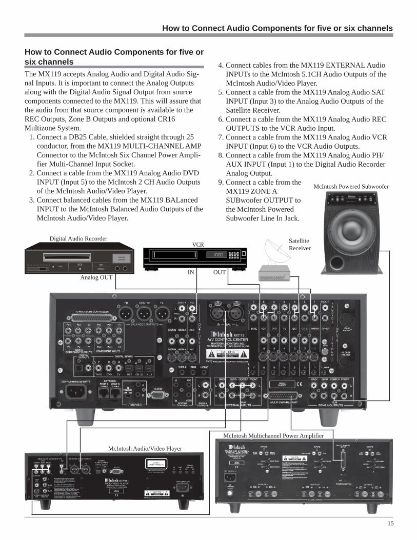
The MX119 accepts Analog Audio and Digital Audio Sig-nal Inputs. It is important to connect the Analog Outputsalong with the Digital Audio Signal Output from sourcecomponents connected to the MX119. This will assure thatthe audio from that source component is available to theREC Outputs, Zone B Outputs and optional CR16Multizone System.
1. Connect a DB25 Cable, shielded straight through 25conductor, from the MX119 MULTI-CHANNEL AMPConnector to the McIntosh Six Channel Power Ampli-fier Multi-Channel Input Socket.
2. Connect a cable from the MX119 Analog Audio DVDINPUT (Input 5) to the McIntosh 2 CH Audio Outputsof the McIntosh Audio/Video Player.
3. Connect balanced cables from the MX119 BALancedINPUT to the McIntosh Balanced Audio Outputs of theMcIntosh Audio/Video Player.
4. Connect cables from the MX119 EXTERNAL AudioINPUTs to the McIntosh 5.1CH Audio Outputs of theMcIntosh Audio/Video Player.
5. Connect a cable from the MX119 Analog Audio SATINPUT (Input 3) to the Analog Audio Outputs of theSatellite Receiver.
6. Connect a cable from the MX119 Analog Audio RECOUTPUTS to the VCR Audio Input.
7. Connect a cable from the MX119 Analog Audio VCRINPUT (Input 6) to the VCR Audio Outputs.
8. Connect a cable from the MX119 Analog Audio PH/AUX INPUT (Input 1) to the Digital Audio RecorderAnalog Output.
9. Connect a cable from theMX119 ZONE ASUBwoofer OUTPUT tothe McIntosh PoweredSubwoofer Line In Jack.
IN OUT
VCR SatelliteReceiver
McIntosh Audio/Video Player
McIntosh Multichannel Power Amplifier
Analog OUT
Digital Audio Recorder
How to Connect Audio Components for five orsix channels
McIntosh Powered Subwoofer

16
How to Connect Audio Components for sevenchannelsThe MX119 accepts Analog Audio and Digital Audio Sig-nal Inputs. It is important to connect the Analog Outputsalong with the Digital Audio Signal Output from sourcecomponents connected to the MX119. This will assure thatthe audio from that source component is available to theVCR1 and 2 Outputs, Zone B and optional CR16Multizone System.
1. Connect balanced cables from the MX119 Zone A FR(Front Right), Front CENTER and FL (Front Left)BALANCED OUTPUTS to the McIntosh Seven Chan-nel Power Amplifier FR (Front Right), Front Centerand FL (Front Left) Balanced Inputs, making sure tomatch up the channel identifications between bothunits.Note: In place of the Balanced Audio Cables, unbalanced
cables may be used.2. Connect unbalanced cables from the MX119 ZONE A
OUTPUTS SURRound Left and Right together withBACK Left and Right Outputs to the McIntosh SevenChannel Power Amplifier LS (Left Surround), RS(Right Surround), RB (Right Back) and LB (Left Back)Inputs, making sure to match up the channel identifica-tions between both units.Note: In place of the unbalanced cables a DB25 cable may
be used.3. Connect a cable from the MX119 Analog Audio IN-
PUTS (Input 5) to the McIntosh 2 CH Audio Outputsof the McIntosh Audio/Video Player.
4. Connect balanced cables from the MX119 ZONE ABALanced Inputs to the McIntosh Balanced AudioOutputs of the McIntosh Audio/Video Player.
5. Connect cables from the MX119 EXTERNAL AnalogAudio INPUTS to the McIntosh 5.1CH Audio Outputsof the McIntosh Audio/Video Player.
6. Connect a cable from the MX119 Analog Audio IN-PUTS (Input 3) to the Analog Audio Outputs of theSatellite Receiver.
7. Connect a cable from the MX119 Analog AudioRECord OUTPUTS to the VCR Audio Input.
8. Connect a cable from the MX119 VCR Analog AudioINPUTS (Input 6) to the VCR Audio Output.
9. Connect a cable from the MX119 PH/AUX Analog Au-dio INPUTS (Input 1) to the Digital Audio RecorderAnalog Output.
10. Connect a cable from the MX119 ZONE ASUBwoofer OUTPUTS to the McIntosh PoweredSubwoofer Line In Jack.
IN OUT
VCR
McIntosh Audio/Video Player
Analog OUT
Digital Audio Recorder

17
SatelliteReceiver
How to Connect Audio Components for seven channels
McIntosh Powered Subwoofer
McIntosh Seven ChannelPower Amplifier

18
McIntosh Audio/Video Player
How to Connect Video Components
How to Connect Video ComponentsThere are three types of Video Signals that can be con-nected to and selected by the MX119; Composite, S-Videoand Component. The built-in Digital Video Processing Cir-cuitry can Up-Convert the desired Composite Input to S-Video; it will also Up-Convert the desired Composite or S-Video Inputs to Component Video. Connect all of the avail-able Source Component Video Outputs (Component, S-Video and Composite), using the appropriate Video Cablesto the MX119. This will assure that video is available tothe Zone B and RECord Outputs. Refer to Video ConverterSetup on page 36 for additional information.
1. Connect video cables from the MX119 DVD VIDEOINPUTS to the McIntosh Video Outputs of the McIn-tosh Audio/Video Player.
IN OUT
VCR
To ACOutlet
2. Connect video cables from the MX119 DVD COMPO-NENT INPUTS 3 to the McIntosh Component VideoOutputs of the McIntosh Audio/Video Player.
3. Connect video cables from the MX119 SAT VIDEOINPUTS to the Video Outputs of a Satellite Receiver.
4. Connect video cables from the MX119 SAT COMPO-NENT INPUTS 1 to the Component Video Outputs ofa Satellite Receiver.
5. Connect video cables from the MX119 VCR INPUTSto the VCR Video Outputs.
6. Connect video cables from the MX119 VCR RECordOUTPUTS to the VCR Video Inputs.
7. Connect video cables from the MX119 MON A COM-PONENT OUTPUTS to the Monitor/TV ComponentVideo Inputs.Note: If the Monitor/TV does not have Component Video
Inputs, then connect the MX119 MON A S-Video orComposite Output(s) instead.
Monitor/TV
Note: If the MX119 A/V SystemControl Center has theTM1 AM/FM TunerModule installed, proceedto page 54 for How toConnect AntennasInformation.
Satellite Receiver

19
Monitor/TV
How to Connect for Zone BThe MX119 is a Dual Zone A/V Control Center. For ZoneB activation, a Power Amplifier and Loudspeakers are re-quired and the addition of a McIntosh Sensor or Keypadallows for more convenient operation. To provide the bestvideo quality for Zone B, it is important to use high qualitycables and keep the cable lengths as short as possible. If S-Video Connections are used, make sure the cable’s signalcarrying wires are individually shielded.
Note: If Zone B will not be connected at this time, proceed tostep 5.
1. Connect a cable from the MX119 POWER CONTROLB Jack to the McIntosh Power Amplifier Power Con-trol In Jack.
2. Connect a cable from the MX119 ZONE B OUTPUTSLeft and Right to the McIntosh Power Amplifier Un-balanced Left and Right Inputs.
McIntosh WK-4 Keypad
McIntosh Power Amplifier
LeftLoudspeaker
RightLoudspeaker
3. Connect a cable from the MX119 KEYPADS ZONE Bto the McIntosh Keypad.
4. Connect a cable from the MX119 MON B S-VideoSocket to the Monitor/TV video input.
5. Connect the MX119 to a live AC Outlet.
How to Connect for Zone B
To ACOutlet

20
Front Panel Controls and Sensor
IR (Infra Red) Sensoraccepts IR signals di-rectly from the RemoteControl
Selects which of the seven Au-dio/Video Sources or Tuner Sig-nal is available at the Zone Aand B Audio/Video Outputs andfor the RECord Outputs
Adjusts the Listen VolumeLevel of all eight channelsfor Zone A and both chan-nels for Zone B
Selects the desired audiooperating mode and selectsthe external eight channelinput
Selects the Trim Func-tion for making audioand front panel displayadjustments
21
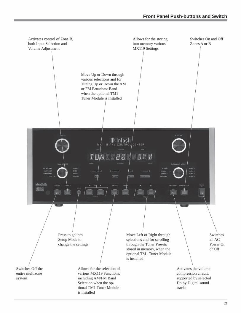
Move Up or Down throughvarious selections and forTuning Up or Down the AMor FM Broadcast Bandwhen the optional TM1Tuner Module is installed
Switches Off theentire multizonesystem
Press to go intoSetup Mode tochange the settings
Activates the volumecompression circuit,supported by selectedDolby Digital soundtracks
Switches On and OffZones A or B
Switchesall ACPower Onor Off
Allows for the selection ofvarious MX119 Functions,including AM/FM BandSelection when the op-tional TM1 Tuner Moduleis installed
Allows for the storinginto memory variousMX119 Settings
Move Left or Right throughselections and for scrollingthrough the Tuner Presetsstored in memory, when theoptional TM1 Tuner Moduleis installed
Front Panel Push-buttons and Switch
Activates control of Zone B,both Input Selection andVolume Adjustment

22
Front Panel Displays
Indicates which TrimParameter has beenselected
Indicates which SurroundMode is in use
Indicates whenZone B FrontControl is active
Indicates whenthe Late NightProcessing hasbeen selected
Indicates when theMX119 is inStandby/On Mode
Indicates Input Selection Status, Volume, TrimAdjustments, Surround Modes, Setup Functions.The Tuner Functions are displayed when theOptional TM1 Module is installed
Indicates when the InputSource selected is processinga Digital Signal
Indicates the name or type ofthe Operating/Decoding Modesthat are in use

23
Notes

24
Remote Control Push-Buttons
Selects one of the availableAudio Sources
Turns AC Power ON or OFF tocertain McIntosh Componentswhen connected via the Data Port
Adjusts the volumelevel up or down
Press to Power the MX119ON or OFF
Use to select tunerpresets, disc tracks orany numbered opera-tion
Mutes the audio
Selects On Screen Func-tions for certain McIntoshDisc Players
Selects the REWindMode on Disc Playersand Tunes Down theAM/FM Dial
Press the push-buttonto illuminate the keys
Press to REVIEW TunerStation Presets and selectcertain functions onMcIntosh Disc Players
Selects the Fast ForwardMode on Disc Players andTunes Up the AM/FMDial
Selects a Disc Player orTape Recorder Functionsand also performs variousfunctions on a variety ofMcIntosh Components
Selects FM Tuner Operat-ing Functions and TrackSelection on certainMcIntosh CD Players
Selects AM Tuner Oper-ating Functions and DiscSelection on certainMcIntosh Disc Players
Press MODE to switchbetween various SurroundModes
Press TRIM and then theLEVEL Push-buttons toadjust various functions
Selects Functions for theMcIntosh Home Control-ler

25
stored in the tuner memory. Press REVIEW a second timeto stop on a station preset and exit the Review process.
Note: The above Tuner Function requires either the optionalTM1 Tuner Module installed in the MX119 or anexternal McIntosh Tuner connected to the MX119.
VolumePress the Up or Down VOLUME Push-button to raiseor lower the listening volume level.
Note: The RECord OUPUTS are not affected by volumechanges.
Acc OnPress ACC ON to turn the power ON to a McIntosh DiscPlayer.
Acc OffPress ACC OFF to turn the power OFF to a McIntosh DiscPlayer.
EPress E to perform various functions on a variety ofMcIntosh Components. It will also pause the playing of adisc or tape player. The E Push-button will also allow forquick exiting from the active menu when in the setupmode.
LightingPress and release the LIGHTING Push-button to momen-tarily illuminate the upper half of the Remote ControlPush-buttons.
Note: While the LIGHTING Push-button is being depressed,the Remote Control will be unable to send a remotecommand. When the LIGHTING Push-button is releasedthe push-buttons will continue to stay illuminated forapproximately three seconds thus allowing you to sendthe desired command. If any of the translucent push-buttons are depressed, they will continue to stayilluminated for approximately three seconds.
How to Operate by Remote Control
How to Operate by Remote Control
The supplied Remote Control is capable of directly control-ling the functions of contemporary McIntosh Source Com-ponents connected to the MX119. Earlier McIntosh sourcecomponents and other brand source components can becontrolled by the MX119 with the addition of a McIntoshRemote Control Translator (RCT).
Note: Your McIntosh Dealer can assist you with theinstallation and operation of the Remote ControlTranslator (RCT).
MutePress the MUTE Push-button to mute audio in the Zonewhere the command is issued. The RECord OUTPUTS arenot affected by the MUTE function. The MX119 FrontPanel Alphanumeric Display will indicate the word Mutefor Zone A. Press MUTE a second time to unmute audio.
ModePress the MODE Push-button to select the Surround Modefrom Cinema 2 to Music 4 plus External Mode for listeningto an Eight Channel Analog Audio Source.
TrimPress the TRIM Push-button, followed by the LEVELUp or Down Push-button to select various sound ad-justments and MX119 Setup Settings.
Input Source SelectionPress one of the appropriate Input Push-buttons to select aprogram source, both audio and video.
Disc and Tape FunctionsUse these push-buttons to operate a DVD Player, CDPlayer, CD Changer or Tape Recorder.
Numbered Push-buttonsPress Push-buttons 0 through 9 to access tuner station pre-sets or CD tracks/discs.
Disc and TrackUse the DISC and TRACK Push-buttons when a CDPlayer or changer is being used.
Tuner Push-buttonsPress the AM or FM Push-button to select the desiredbroadcast band. Press and release the Channel Up orDown Push-button to move from station to station. Pressand hold a Channel Up or Down Push-button to movecontinuously from station to station. Press REVIEW tostart the automatic brief audition of each of the presets
26
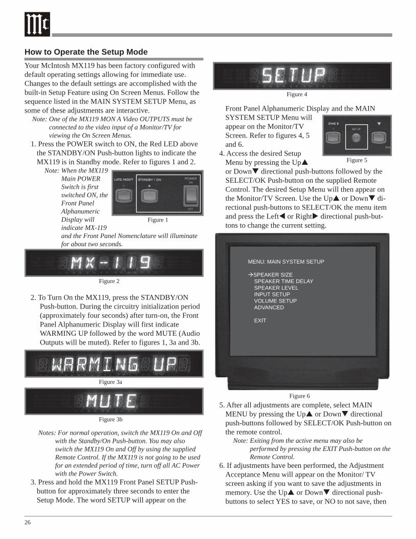
How to Operate the Setup ModeYour McIntosh MX119 has been factory configured withdefault operating settings allowing for immediate use.Changes to the default settings are accomplished with thebuilt-in Setup Feature using On Screen Menus. Follow thesequence listed in the MAIN SYSTEM SETUP Menu, assome of these adjustments are interactive.
Note: One of the MX119 MON A Video OUTPUTS must beconnected to the video input of a Monitor/TV forviewing the On Screen Menus.
1. Press the POWER switch to ON, the Red LED abovethe STANDBY/ON Push-button lights to indicate theMX119 is in Standby mode. Refer to figures 1 and 2.
Note: When the MX119Main POWERSwitch is firstswitched ON, theFront PanelAlphanumericDisplay willindicate MX-119and the Front Panel Nomenclature will illuminatefor about two seconds.
2. To Turn On the MX119, press the STANDBY/ONPush-button. During the circuitry initialization period(approximately four seconds) after turn-on, the FrontPanel Alphanumeric Display will first indicateWARMING UP followed by the word MUTE (AudioOutputs will be muted). Refer to figures 1, 3a and 3b.
Notes: For normal operation, switch the MX119 On and Offwith the Standby/On Push-button. You may alsoswitch the MX119 On and Off by using the suppliedRemote Control. If the MX119 is not going to be usedfor an extended period of time, turn off all AC Powerwith the Power Switch.
3. Press and hold the MX119 Front Panel SETUP Push-button for approximately three seconds to enter theSetup Mode. The word SETUP will appear on the
Front Panel Alphanumeric Display and the MAINSYSTEM SETUP Menu willappear on the Monitor/TVScreen. Refer to figures 4, 5and 6.
4. Access the desired SetupMenu by pressing the Upor Down directional push-buttons followed by theSELECT/OK Push-button on the supplied RemoteControl. The desired Setup Menu will then appear onthe Monitor/TV Screen. Use the Up or Down di-rectional push-buttons to SELECT/OK the menu itemand press the Left or Right directional push-but-tons to change the current setting.
5. After all adjustments are complete, select MAINMENU by pressing the Up or Down directionalpush-buttons followed by SELECT/OK Push-button onthe remote control.
Note: Exiting from the active menu may also beperformed by pressing the EXIT Push-button on theRemote Control.
6. If adjustments have been performed, the AdjustmentAcceptance Menu will appear on the Monitor/ TVscreen asking if you want to save the adjustments inmemory. Use the Up or Down directional push-buttons to select YES to save, or NO to not save, then
Figure 4
Figure 1
Figure 5
Figure 3b
Figure 3a
Figure 6
MENU: MAIN SYSTEM SETUP
SPEAKER SIZESPEAKER TIME DELAYSPEAKER LEVELINPUT SETUPVOLUME SETUPADVANCED
EXIT
Figure 2

27
The following listings indicate the factory default settings.Refer to the listed page number for instructions on how tochange a default setting:
Default Settings
Speaker Size:Speaker Type Speaker Setting Refer to PageFront ................................. Small ........................................... 28Center ............................... Small ........................................... 28Surround .......................... Small ........................................... 28Back Surr ......................... Small2 ......................................... 28Subwoofer1 ....................... Yes .............................................. 28Sub Xover ........................ 80Hz ........................................... 28MC Bass Mode ................ Off ............................................... 28
Speaker Time Delay:Speaker Location Viewing Distance Refer to PageAll Locations ................... 10 feet ......................................... 30
Speaker Level:Speaker Location Initial Level Refer to PageAll Locations ................... 0 .................................................. 31
Analog Inputs (Zones A and B):Number Name Refer to Page 0 ...................................... TUN ............................................ 33 1 ...................................... PH/AUX ..................................... 33 2 ...................................... CD(2) .......................................... 33 3 ...................................... SAT ............................................. 33 4 ...................................... TV ............................................... 33 5 ...................................... DVD ........................................... 33
Figure 7
ADJUSTMENTS HAVE BEEN MADEDO YOU WANT TO SAVE THEM?
NO YES
press the SELECT/OK Push-button to exit the SetupMode and return to normal operation. Refer to figure 7.
Setup
6 ............................................ VCR ..................................... 33 7 ............................................ TAPE ................................... 33
Digital Inputs (Zone A):Letter Type Name Refer to Page
A .............. Optical .............. AUX .................................... 34B .............. Optical .............. CD(2) ................................... 34C .............. Optical .............. SAT ...................................... 34D .............. Coaxial .............. TV ........................................ 34E ............... Coaxial .............. DVD .................................... 34F ............... Coaxial .............. TAPE ................................... 34
Zone A Analog Input:Number Setting Refer to Page
0 - 7 ...................................... RCA ..................................... 34
Surr (Surround) Mode Default:Number Setting Refer to Page
0 - 7 ...................................... LAST ................................... 35
Video Power Control:Number Power Control Refer to Page
0 - 7 ...................................... ON ....................................... 35
Component Video Inputs (Zone A):Number Name Refer to Page
1 ......................................... SAT ...................................... 352 ......................................... TV ........................................ 353 ......................................... DVD .................................... 35
Video Converter:Number Conversion Refer to Page
0 - 7 ...................................... OFF ..................................... 36
Volume Setup:Description Initial Setting Refer to PageZone A Volume Preset: ............ Last ...................................... 38Zone A Volume Maximum: ..... 99 ........................................ 38
Zone B Volume Preset: ............ 20 ........................................ 38Zone B Volume Maximum: ..... 99 ........................................ 38
Advanced Digital Settings:Function Setting Refer to PageRC Toggle: ............................... OFF ...................................... 39
Advanced Input Select Power:Function Setting Refer to PageInput Select Power: ................ OFF ...................................... 39
1The Low Frequency Effect (LFE) Sound Information is usuallyassigned to the Subwoofer Channel. If the Subwoofer Channel isswitched Off and one or more of the Front Channel Loudspeakersare set to Large in the Speaker Size Setup Menu, the LFE SoundInformation will be redirected to the Large Loudspeaker(s).

28
How to Adjust for Loudspeaker SizeA Home Theater System can include a variety of Loud-speakers with various capabilities. The LARGE listing re-fers to the Loudspeaker’s capability for reproducing bassfrequencies down to 35Hz within -3dB of the midrange fre-quencies. If a Loudspeaker can not reproduce bass frequen-cies down to 35Hz within -3dB of the midrange frequen-cies, it is considered SMALL. If you do not have aSubwoofer, you must have Front (Left and Right) Loud-speakers that are LARGE in order to hear the low frequen-cies below the Subwoofer Crossover Setting of 80Hz. Ifyou are unsure as to the bass performance capabilities ofyour Loudspeakers, select the SMALL setting.1. Press and hold the Front Panel SETUP Push-button for
approximately three seconds to enter the Setup Mode.The word SETUP will appear on the MX119 FrontPanel Alphanumeric Display and the MAIN SYSTEMSETUP Menu will appear on the Monitor/TV screen.Refer to figure 6 on page 26.
2. Using the Up or Down directional push-buttons,select Speaker Size on the On-Screen Menu, followedby the SELECT/OK Push-button on the Remote Con-trol. Refer to figure 8.Notes: The very first time the SPEAKER SIZE Menu is
accessed, the factory default settings will beindicated. In the Speaker Size Menu Setting Options,the number after the name of Small or Large refers toquantity of Loudspeakers. If the setting for the BackSurround Loudspeaker is Small 1 (BSL - BackSurround Left), only the Zone A Back Output LeftChannel will have audio output.
3. Select the appropriate Loudspeaker location and typeby using the Up or Down directional push-buttonsto select first the menu item and then press the Leftor Right directional push-buttons to change the cur-rent setting.Notes: When the Front Loudspeakers are set to Small, the
options in the Speaker Size Setup Menu for the Centerand Surround Loudspeakers are Small or None; theSubwoofer Loudspeaker will be set to the On position.If the Surround Loudspeakers are set to Small, theoptions in the Speaker Size Setup Menu for the BackSurrround Loudspeaker are Small 1(BSL), Small 2 orNone. When the Small 1 (BSL) setting is selected, theBACK Surround Right Channel ZONE A OUTPUTwill be switched Off. A chart has been provided on thenext page to record your system settings.
4. When all of the settings on the SPEAKER SIZE Menuagree with the Loudspeakers in your Home TheaterSystem, perform the SUB Crossover and/or the MCBASS MODE adjustments or if no adjustments areneeded, then continue to the SPEAKER TIME DELAYSettings. If you do not wish to perform SPEAKERTIME DELAY adjustments at this time, select MAINMENU from the menu. The MAIN SYSTEM SETUPMenu will reappear on the Monitor/TV screen and pro-ceed to the next step.
5. Select EXIT from the MAIN SYSTEM SETUP Menu.If you are satisfied with the changes that you havemade, select YES to save those changes or NO not tosave them. The MX119 will then return to normal op-eration. Refer to figure 7 on page 27.
Figure 8
MENU: SPEAKER SIZE
FRONT: Small CENTER: Small SURROUND: Small BACK SURROUND: Small2 SUBWOOFER: Yes SUB Crossover: 80Hz MC BASS MODE OFF
MAIN MENU
29
Sub CrossoverThe MX119 incorporates a built-in Electronic Crossover.The Crossover will redirect all of the audio frequencies be-low the crossover frequency setting to the Subwoofer andall the frequencies above the setting to the appropriate re-maining Home Theater Loudspeakers. The default settingfor the SUB Crossover frequency setting is 80 Hz, which isthe correct frequency for most Home Theater LoudspeakerSystems. Refer to figure 8 and perform the following stepsto change the setting.
6. Using the Up or Down directional push-buttons,select SUB Crossover from the SPEAKER SIZE On-Screen Menu, followed by pressing the Left orRight directional push-buttons to change the cross-over frequency to the desired setting.Notes: The range of adjustment is from 60Hz to 120Hz in
10Hz increments. When the Input Source is Analogand the Surround Mode is set to STEREO (theAlphanumeric Front Panel Display will indicatePURE STEREO) the crossover frequency will defaultto 80Hz.
7. Next perform the MC Bass Mode adjustment below orif no adjustment is needed, then continue to theSPEAKER TIME DELAY Settings. If you do not wishto perform SPEAKER TIME DELAY adjustments atthis time, select MAIN MENU from the menu. TheMAIN SYSTEM SETUP Menu will reappear on theMonitor/TV screen and proceed to the next step.
8. Select EXIT from the MAIN SYSTEM SETUP Menu.If you are satisfied with the changes that you may havemade, select YES to save those changes or NO not tosave them. The MX119 will then return to normal op-eration. Refer to figure 7 on page 27.
SETUP, con’t
Loudspeaker Default Setting New Setting
Front (L&R) Small
Center Small
Surround (L&R) Small
Back Surround Small 2
Subwoofer YesSub Crossover 80HzMC Bass Off
Loudspeaker Size
MC Bass ModeWhen a Home Theater System contains Loudspeakers thatare refered to as Large, the Bass Management Circuitrywill direct all the Low Frequency Sounds away from theSubwoofer and to the Large Loudspeakers. With the MCBASS MODE set to ON the Low Frequency Sounds aresent to both the Large Loudspeakers and to the Subwoofer,thus increasing the total low frequency output of the HomeTheater System. The default setting for the MC BASSMODE is OFF. Refer to figure 8 and perform the followingsteps to switch it On.
Note: The MC BASS Mode is only active when the Source iseither a Two Channel Analog or Digital Signal.
9. Using the Up or Down directional push-buttons,select MC BASS MODE from the SPEAKER SIZEOn-Screen Menu, followed by pressing the Left orRight directional push-buttons to activate the circuit.Select MAIN MENU and the MAIN SYSTEM SETUPMenu will reappear on the Monitor/TV screen.
10. Next continue to the SPEAKER TIME DELAY Set-tings. If you do not wish to perform SPEAKER TIMEDELAY adjustments at this time, select MAIN MENUfrom the menu. The MAIN SYSTEM SETUP Menuwill reappear on the Monitor/TV screen and proceed tothe next step.
11. Select EXIT from the MAIN SYSTEM SETUP Menu.If you are satisfied with the changes that you havemade, select YES to save those changes or NO not tosave them. The MX119 will then return to normal op-eration. Refer to figure 7 on page 27.

30
How to Adjust Loudspeaker Time DelayThe following Time Delay Adjustments will electronicallycompensate for different Loudspeaker distances from theListening/Viewing Area. Refer to figure 9. Time delay ismeasured in feet. The delays can be adjusted from 1 foot to20 feet in one foot increments for each Loudspeaker.
Note: Before performing the TIME DELAY adjustments, youmust first have completed the SPEAKER SIZEadjustments.
1. Press and hold the Front Panel SETUP Push-button forapproximately three seconds to enter the Setup Mode.The word SETUP will appear on the MX119 FrontPanel Display and the MAIN SYSTEM SETUP Menuwill appear on the Monitor/TV screen. Refer to figure6 on page 26.
2. Using the Up or Down directional push-buttons,select SPEAKER TIME DELAY on the On-ScreenMenu, followed by the SELECT/OK Push-button onthe Remote Control. Refer to figure 10.Note: The very first time the SPEAKER TIME DELAY
MENU is accessed, the factory default settings will beindicated.
3. Measure the distance from the Listening/Viewing Areato each of the Loudspeakers. A table has been providedto record the measurements and settings.Note: A distance measurement that contains fractions of a
foot, should be rounded up or down to the nearestwhole number for this procedure.
4. Select the appropriate Loudspeaker location and typeby using the Up or Down directional push-buttonsto select first the menu item and then press the Leftor Right directional push-buttons to change the cur-
rent setting. When all of the settings on the SPEAKERTIME DELAY Menu agree with the Loudspeaker mea-sured distances in your Home Theater System, selectMAIN MENU. The MAIN SYSTEM SETUP Menuwill reappear on the Monitor/TV screen.
5. Continue next to the SPEAKER LEVEL Settings. Ifyou do not wish to perform SPEAKER LEVEL Adjust-ments at this time, select MAIN MENU from themenu. The MAIN SYSTEM SETUP Menu will reap-pear on the Monitor/TV screen and proceed to the nextstep.
6. Select EXIT from the MAIN SYSTEM SETUP Menu.If you are satisfied with the changes that you havemade, select YES to save those changes or NO not tosave them. The MX119 will then return to normal op-eration. Refer to figure 7 on page 27.
Figure 9
Location Default Setting New Setting
Left Front 10 feet
Center 10 feet
Right Front 10 feet
Right Surround 10 feet
Right Back Sur 10 feet
Left Back Sur 10 feet
Left Surround 10 feet
Subwoofer 10 feet
Loudspeaker Time Delay
Figure 10
MENU: SPEAKER TIME DELAYLEFT FRONT 10FT
CENTER 10FT RIGHT FRONT 10FT RIGHT SURROUND 10FT RIGHT BACK SUR 10FT LEFT BACK SUR 10FT LEFT SURROUND 10FT SUBWOOFER 10FT
MAIN MENU

31
A properly setup Home Theater Surround Sound Systemwill have all Loudspeaker levels adjusted to the same vol-ume level in the Listening/Viewing Area. The MX119 in-cludes a built-in test signal generator and its output isswitched into each Loudspeaker, either automatically ormanually. The correct volume level for each Loudspeakercan be determined in the Listening/Viewing area, eitherwith a sound pressure meter or by listening. Level adjust-ments are made in 1dB steps, over a plus or minus 12dBrange, by using the Remote Control Left and Right di-rectional push-buttons.
Notes: Before adjusting the SPEAKER LEVELs, perform theSPEAKER SIZE and SPEAKER TIME DELAYadjustments first. The SPEAKER LEVEL On-ScreenDisplay will only indicate channels that have beenswitched On in the SPEAKER SIZE Menu. A sound levelpressure meter will greatly aid in adjusting theLoudspeaker levels and the Left Front LoudspeakerVolume level can serve as a reference.
1. Press and hold the Front Panel SETUP Push-button ap-proximately three seconds to enter the Setup Mode.The word SETUP will appear on the MX119 FrontPanel Display and the MAIN SYSTEM SETUP Menuwill appear on the Monitor/TV screen. Refer to figure6 on page 26.
2. Using the Up or Down directional push-buttons,select SPEAKER LEVEL on the On-Screen Menu, fol-lowed by the SELECT/OK Push-button on the RemoteControl. Refer to figure 11.Note: The very first time the SPEAKER LEVEL MENU is
accessed, the factory default settings will beindicated.
3. Determine whether you wish to use the Automatic (re-quires less push-button presses) or Manual (quickerwhen used with a sound pressure meter) LoudspeakerLevel switching mode. For Automatic switching, pro-ceed to Step 4. For Manual switching, proceed to Step11 on the next page.
Automatic Loudspeaker Level Switching4. Using the Left or Right directional push-buttons,
select AUTO MODE from the SPEAKER LEVEL On-Screen Menu, followed by pressing the SELECT/OKPush-button to activate the Automatic LoudspeakerLevel Switching Mode. The test signal will start cy-cling continuously through all Loudspeakers in 2-sec-ond intervals. Refer to figure 12.
5. While in the Listening/Viewing area, note the volumelevels from each of the Loudspeakers as the test signalswitches. If you determine that the test signal volume
How to Adjust Loudspeaker Levels
Figure 11
MENU: SPEAKER LEVELOFF
LEFT FRONT 0CENTER 0RIGHT FRONT 0RIGHT SURROUND 0RIGHT BACK SURR 0LEFT BACK SURR 0LEFT SURROUND 0SUBWOOFER 0
MAIN MENU
is louder or softer in any of the Loudspeakers, the lev-els should be adjusted so you hear the same test signalvolume from all of the Loudspeakers.
6. Adjust the volume of the test signal by pressing theLeft or Right directional push-buttons on the Re-mote Control. If an adjustment is made on a Loud-speaker, there is an additional 2-second time intervalbefore the system switches to the next Loudspeaker. Asa level is changed, the on-screen display instantly indi-cates the level change with numbers or minus numbers.
7. As the test signal switches to succeeding Loudspeak-
SETUP, con’t
Figure 12
MENU: SPEAKER LEVELAUTO MODE: PRESS SELECT
LEFT FRONT 0CENTER 0RIGHT FRONT 0RIGHT SURROUND 0RIGHT BACK SURR 0LEFT BACK SURR 0LEFT SURROUND 0SUBWOOFER 0
MAIN MENU

32
Figure 14
ers, repeat the level adjustment process until the testsignal volume levels of all the Loudspeakers are thesame. The Loudspeaker level cycling mode can be re-peated as often as necessary.
8. Press the SELECT/OK Push-button to switch Off theAutomatic Loudspeaker Level Switching Mode. Referto figure 13.
9. Continue next to the INPUT SETUP. If you do not wishto perform INPUT SETUP Adjustments at this time,select MAIN MENU from the menu. The MAIN SYS-TEM SETUP Menu will reappear on the Monitor/TVscreen and proceed to the next step.
10. Select EXIT from the MAIN SYSTEM SETUP Menu.If you are satisfied with the changes that you may havemade, select YES to save those changes or NO not tosave them. The MX119 will then return to normal op-eration. Refer to figure 7 on page 27.
Manual Loudspeaker Level Switching11. Using the Left or Right directional push-buttons,
select MANUAL MODE from the SPEAKER LEVELOn-Screen Menu, followed by pressing the SELECT/OK Push-button to activate the Manual LoudspeakerLEVEL Switching Mode. Refer to figure 14.
12. Adjust the volume of the Loudspeaker by pressing theLeft or Right directional push-buttons on the Re-mote Control.
13. Using the Up or Down directional push-buttons,select the next Loudspeaker and perform the level ad-justing procedure. Continue this for each of the remain-
ing Loudspeakers. Repeat this as often as necessary un-til you are satisfied that the volume levels of all theLoudspeakers are the same.
14. Press the SELECT/OK Push-button to switch Off theManual Loudspeaker Level Switching Mode.
15. Continue next to the INPUT SETUP. If you do notwish to perform INPUT SETUP Adjustments at thistime, select MAIN MENU from the menu. The MAINSYSTEM SETUP Menu will reappear on the Monitor/TV screen and proceed to the next step.
16. Select EXIT from the MAIN SYSTEM SETUP Menu.If you are satisfied with the changes that you may havemade, select YES to save those changes or NO not tosave them. The MX119 will then return to normal op-eration. Refer to figure 7 on page 27.
Location Default Setting New Setting
Left Front 0dB
Center 0dB
Right Front 0dB
Right Surround 0dB
Right Back Sur 0dB
Left Back Sur 0dB
Left Surround 0dB
Subwoofer 0dB
Loudspeaker Levels
Figure 13
MENU: SPEAKER LEVELAUTO MODE: SELECT TO STOP
LEFT FRONT 0CENTER 0RIGHT FRONT 0RIGHT SURROUND 0RIGHT BACK SURR 0LEFT BACK SURR 0LEFT SURROUND 0SUBWOOFER 0
MAIN MENU
MENU: SPEAKER LEVELMANUAL MODE: PRESS SELECT
LEFT FRONT 0CENTER 0RIGHT FRONT 0RIGHT SURROUND 0RIGHT BACK SURR 0LEFT BACK SURR 0LEFT SURROUND 0SUBWOOFER 0
MAIN MENU

33
The MX119 has eight Analog Audio Inputs numbered 0through 7, six Digital Audio Inputs lettered A through Fand three Component Video Inputs numbered 1 through 3.These inputs already have assigned titles and associationsthat will allow for immediate hookup, operation and enjoy-ment.
If these starting assignments and associations do notmatch up with components in your system, they may bereassigned from the default settings. The following ex-ample will illustrate how to rename the TV Inputs, bothAudio and Video to DVD2. When the Input Selector is ro-tated to select what was originally the TV Input, DVD2will now appear on the Front Panel Alphanumeric Display.The Surround Mode, Video Power Control, Video Con-verter Input and Component Video can also be set for eachInput.
Notes: 1. The very first time the INPUT SETUP is accessed, thedefault settings will be indicated.
2. Unused Inputs may be switched Off so that they willnot appear when rotating through the input sourcechoices using the Input Selector and also will not beavailable when using the Remote Control or Keypad.
3. If the MX119 is connected to either a CR16 or CR12Multizone Controller, refer to Important Informationnote number 8 on page 5.
1. Press and hold the Front Panel SETUP Push-button ap-proximately three seconds to enter the Setup Mode.The word SETUP will appear on the MX119 FrontPanel Display and the MAIN SYSTEM SETUP Menuwill appear on the Monitor/TV screen. Refer to figure6 on page 26.
2. Using the Up or Down directional push-buttons onthe Remote Control, select INPUT SETUP on the On-Screen Menu, followed by the SELECT/OK Push-but-ton. Refer to figure 6 on page 26.
3. Using the Up or Down directional push-buttons,select SOURCE INPUT from the On-Screen Menu,followed by pressing the Left or Right directionalpush-buttons to select Input Number 4 - IR-TV. Referto figure 15.
Note: The information displayed after the Source InputNumber indicates which IR Remote ControlCommand selects the input.
Analog Audio/Video Input Title4. Using the Up or Down directional push-buttons,
select TITLE, followed by pressing the SELECT/OKPush-button. The On-Screen Menu Title can now bechanged from the default name. Refer to figure 16.
5. Using the Up or Down directional push-buttons,select “D” as the first character of the new title.
How to Change the Input Setup
Note: The TITLE may be up to 4 characters in lengthincluding (0 thru 9) and (A thru Z).
6. Press the Right directional push-button to select thesecond character position of the title.
7. Using the Up or Down directional push-buttons toselect “V” the second character of the title.
8. Select the two remaining characters “D” and “2” of thetitle by using the directional push-buttons.
9. Press the SELECT/OK Push-button once and thenpress the Down directional push-button.
10. Proceed to the Digital Input Setting. If you do not
SETUP, con’t
MENU: INPUT SETUP
SOURCE INPUT 4 - IR-TVTITLE TVDIGITAL INPUT COAX D LKZONE A ANALOG INPUT RCASURR MODE LASTVIDEO POWER ONCOMPONENT VIDEO NONE
VIDEO CONV INPUT OFFMAIN MENU
Figure 15
Figure 16
MENU: INPUT SETUP
SOURCE INPUT 4 - IR-TVTITLE ADIGITAL INPUT COAX D LKZONE A ANALOG INPUT RCASURR MODE LASTVIDEO POWER ONCOMPONENT VIDEO NONE
VIDEO CONV INPUT OFFMAIN MENU

34
wish to perform Digital Input Setting at this time, pro-ceed to the ZONE A Analog Input Setting.
Digital InputThere are three Optical Digital Inputs and three CoaxialDigital Inputs available for assignment with any of theeight Audio Inputs. The following example describes howto reassign Digital Input A, which by default has been as-signed to Input Number 1 PH/AUX, over to the VCR Input(6) instead.11. Using the Up or Down directional push-buttons,
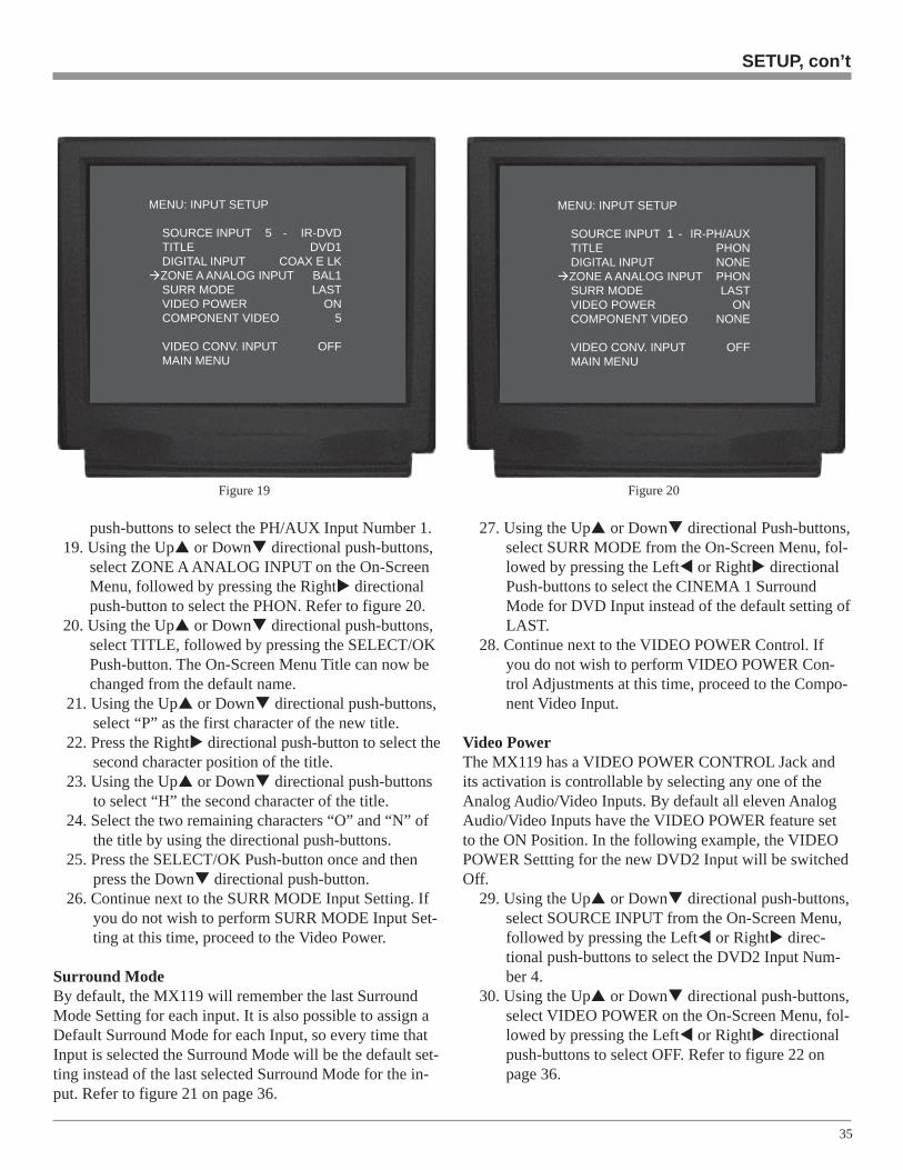
select SOURCE INPUT from the On-Screen Menu,followed by pressing the Left or Right directionalpush-buttons to select the PH/AUX Input Number 1.
12. Using the Up or Down directional push-buttons,select DIGITAL INPUT on the On-Screen Menu, fol-lowed by pressing the Left or Right directionalpush-buttons to select NONE for the Digital Input.Refer to figure 17.
13. Using the Up or Down directional push-buttons,select SOURCE INPUT from the On-Screen Menu,followed by pressing the Left or Right directionalpush-buttons to select the VCR Input Number 6.
14. Using the Up or Down directional push-buttons,select DIGITAL INPUT on the On-Screen Menu, fol-lowed by pressing the Left or Right directionalpush-buttons to select the OPTICAL A LK Digital In-put. Refer to figure 17.
Notes: A Digital Input may be assigned to multiple AudioInputs. The “LK” after the Digital Input Nameindicates the MX119 will stay locked into the
Digital Mode even with an interruption of theSignal. When the Lock is Off, the MX119 will switchto the associate Analog Input Signal if there isinterruption of the Digital Signal.
15. Continue next to the ZONE A Analog Input Setting. Ifyou do not wish to perform ZONE A Analog InputSetting at this time, proceed to the SURR MODE set-ting.
ZONE A Analog InputThe MX119 has one Stereo Balanced Input that may be as-signed to any of the eight Audio Inputs instead of unbal-anced (RCA Type) jacks. The AUX Input also includes theoption of connecting a Turntable with a Moving Magnettype Phono Cartridge to PH/AUX unbalanced jacks. In thesteps below, the BALanced Input will be assigned to theDVD Input and the PH/AUX Input will change over to aPhono Input.
16. Using the Up or Down directional push-buttons,select SOURCE INPUT from the On-Screen Menu,followed by pressing the Left or Right directionalpush-buttons to select the DVD Input Number 5.
17. Using the Up or Down directional push-buttons,select ZONE A ANALOG INPUT on the On-ScreenMenu, followed by pressing the Right directionalpush-button to select BAL. Refer to figure 19.Note: The BALanced Input may be assigned to multiple
Audio Inputs.18. Using the Up or Down directional push-buttons,
select SOURCE INPUT from the On-Screen Menu,followed by pressing the Left or Right directional
Figure 17
MENU: INPUT SETUP
SOURCE INPUT 1 -IR-PH/AUXTITLE AUXDIGITAL INPUT NONEZONE A ANALOG INPUT RCASURR MODE LASTVIDEO POWER ONCOMPONENT VIDEO NONE
VIDEO CONV. INPUT OFFMAIN MENU
Figure 18
MENU: INPUT SETUP
SOURCE INPUT 6 - IR-VCRTITLE VCRDIGITAL INPUT OPT A LKZONE A ANALOG INPUT RCASURR MODE LASTVIDEO POWER ONCOMPONENT VIDEO NONE
VIDEO CONV. INPUT OFFMAIN MENU
35
push-buttons to select the PH/AUX Input Number 1.19. Using the Up or Down directional push-buttons,
select ZONE A ANALOG INPUT on the On-ScreenMenu, followed by pressing the Right directionalpush-button to select the PHON. Refer to figure 20.
20. Using the Up or Down directional push-buttons,select TITLE, followed by pressing the SELECT/OKPush-button. The On-Screen Menu Title can now bechanged from the default name.
21. Using the Up or Down directional push-buttons,select “P” as the first character of the new title.
22. Press the Right directional push-button to select thesecond character position of the title.
23. Using the Up or Down directional push-buttonsto select “H” the second character of the title.
24. Select the two remaining characters “O” and “N” ofthe title by using the directional push-buttons.
25. Press the SELECT/OK Push-button once and thenpress the Down directional push-button.
26. Continue next to the SURR MODE Input Setting. Ifyou do not wish to perform SURR MODE Input Set-ting at this time, proceed to the Video Power.
Surround ModeBy default, the MX119 will remember the last SurroundMode Setting for each input. It is also possible to assign aDefault Surround Mode for each Input, so every time thatInput is selected the Surround Mode will be the default set-ting instead of the last selected Surround Mode for the in-put. Refer to figure 21 on page 36.
27. Using the Up or Down directional Push-buttons,select SURR MODE from the On-Screen Menu, fol-lowed by pressing the Left or Right directionalPush-buttons to select the CINEMA 1 SurroundMode for DVD Input instead of the default setting ofLAST.
28. Continue next to the VIDEO POWER Control. Ifyou do not wish to perform VIDEO POWER Con-trol Adjustments at this time, proceed to the Compo-nent Video Input.
Video PowerThe MX119 has a VIDEO POWER CONTROL Jack andits activation is controllable by selecting any one of theAnalog Audio/Video Inputs. By default all eleven AnalogAudio/Video Inputs have the VIDEO POWER feature setto the ON Position. In the following example, the VIDEOPOWER Settting for the new DVD2 Input will be switchedOff.
29. Using the Up or Down directional push-buttons,select SOURCE INPUT from the On-Screen Menu,followed by pressing the Left or Right direc-tional push-buttons to select the DVD2 Input Num-ber 4.
30. Using the Up or Down directional push-buttons,select VIDEO POWER on the On-Screen Menu, fol-lowed by pressing the Left or Right directionalpush-buttons to select OFF. Refer to figure 22 onpage 36.
SETUP, con’t
Figure 20
MENU: INPUT SETUP
SOURCE INPUT 1 - IR-PH/AUXTITLE PHONDIGITAL INPUT NONEZONE A ANALOG INPUT PHONSURR MODE LASTVIDEO POWER ONCOMPONENT VIDEO NONE
VIDEO CONV. INPUT OFFMAIN MENU
Figure 19
MENU: INPUT SETUP
SOURCE INPUT 5 - IR-DVDTITLE DVD1DIGITAL INPUT COAX E LKZONE A ANALOG INPUT BAL1SURR MODE LASTVIDEO POWER ONCOMPONENT VIDEO 5
VIDEO CONV. INPUT OFFMAIN MENU

36
31. If you do not wish to perform COMPONENTVIDEO Input Adjustments at this time, proceed toVideo Converter Input.
Component Video InputThe MX119 has Electronic Input Switching for three Com-ponent Video Sources and they may be assigned to any ofthe eight Analog Audio/Digital Inputs. The following ex-ample describes how to reassign COMPONENT 1 INVideo Input, which by default has been assigned to SATInput 3, over to the VCR Input 6.
Note: The MX119 allows for assigning a Component VideoInput to multiple Analog Audio/Digital Inputs orswitched Off.
32. Using the Up or Down directional push-buttons,select SOURCE INPUT from the On-Screen Menu,followed by pressing the Left or Right direc-tional push-buttons to select the SAT Input, Number3. Using the Up or Down directional push-but-tons, select COMPONENT VIDEO on the On-Screen Menu, followed by pressing the Left orRight directional push-buttons to select NONE.
33. Using the Up or Down directional push-buttons,select SOURCE INPUT from on the On-ScreenMenu, followed by pressing the Left or Rightdirectional push-buttons to select VCR Input 6. Referto figure 23.
34. Using the Up or Down directional push-buttons,select COMPONENT VIDEO from the On-Screen
Menu, followed by pressing the Left or Rightdirectional push-buttons to select the Number 1.
35. If you do not wish to perform VIDEO CON-VERTER Adjustments at this time, proceed to Howto Change the Volume Setup on page 38.
Video ConverterThe MX119 Video Converter feature allows the Up-Con-versions of Composite Video Signals to S-Video andComponent Video; S-Video Input Signals may be con-verted to Component Video. This will provide better pic-ture quality and will simplify video connections and op-eration of the TV/Monitor. In the following example, theCD(2) Input 2 has a S-Video Signal and it will be con-verted to Component Video.
36. Using the Up or Down directional push-but-tons, select SOURCE INPUT from the On-ScreenMenu, followed by pressing the Left or Rightdirectional push-buttons to select the CD(2) Input,Number 2.
37. Using the Up or Down directional push-but-tons, select VIDEO CONV. INPUT on the On-Screen Menu, followed by pressing the Left orRight directional push-buttons to select S-VID.Refer to figure 24.
38. Using the Up or Down directional push-but-tons, select MAIN MENU on the On-Screen Menuand press the SELECT/OK Push-button.
Figure 22
MENU: INPUT SETUP
SOURCE INPUT 4 - IR-TVTITLE DVD2DIGITAL INPUT COAX D LKZONE A ANALOG INPUT RCASURR MODE CINEMA 1VIDEO POWER OFFCOMPONENT VIDEO NONE
VIDEO CONV. INPUT OFFMAIN MENU
Figure 21
MENU: INPUT SETUP
SOURCE INPUT 4 - IR-TVTITLE DVD2DIGITAL INPUT COAX D LKZONE A ANALOG INPUT RCASURR MODE CINEMA 1VIDEO POWER ONCOMPONENT VIDEO NONE
VIDEO CONV. INPUT OFFMAIN MENU

37
SETUP, con’t
Figure 24
MENU: INPUT SETUP
SOURCE INPUT 4 - IR-TVTITLE DVD2DIGITAL INPUT COAX D LKZONE A ANALOG INPUT RCASURR MODE CINEMA 1VIDEO POWER OFFCOMPONENT VIDEO 4
VIDEO CONV. INPUT S-VIDMAIN MENU
Figure 23
MENU: INPUT SETUP
SOURCE INPUT 6 - IR-VCRTITLE VCRDIGITAL INPUT OPT A LKZONE A ANALOG INPUT RCASURR MODE LASTVIDEO POWER OFFCOMPONENT VIDEO NONE
VIDEO CONV. INPUT OFFMAIN MENU
Number Title Default Setting New Setting Default Setting New Setting Default Setting New Setting
0 TUNER ON - OFF
1 PH/AUX ON - OFF
2 CD(2) ON - OFF
3 SAT ON 1 OFF
4 TV ON 2 OFF
5 DVD ON 3 OFF
6 VCR ON - OFF
7 TAPE ON - OFF
Video Inputs Source SettingsVideo Power Control Component Video Source Video Input Converter
38. Continue next to the VOLUME SETUP on page 38.If you do not wish to perform VOLUME SETUP Ad-justments at this time, select MAIN MENU from themenu. The MAIN SYSTEM SETUP Menu will reap-pear on the Monitor/TV screen and proceed to thenext step.
39. Select EXIT from the MAIN SYSTEM SETUPMenu. If you are satisfied with the changes that youmay have made, select YES to save those changes orNO not to save them. The MX119 will then return tonormal operation. Refer to figure 7 on page 27.
Number Default Title New Title Default Input New Input
0 TUNER -
1 PH/AUX A-Optical
2 CD(2) B-Optical
3 SAT C-Optical
4 TV D-Coaxial
5 DVD E-Coaxial
6 VCR -
7 TAPE F-Coaxial
Analog and Digital Audio Input Source SettingsDigital Input

38
How to Change the Volume SetupThe MX119 has provisions for setting the wake-up volumelistening level for Zones A and B. A maximum volume lis-tening level can also be set for both zones.1. Press and hold the Front Panel SETUP Push-button ap-
proximately three seconds to enter the Setup Mode.The word SETUP will appear on the MX119 FrontPanel Display and the MAIN SYSTEM SETUP Menuwill appear on the Monitor/TV screen. Refer to figure6 on page 26.
2. Using the Up or Down directional push-buttons onthe Remote Control, select VOLUME SETUP on theOn-Screen Menu, followed by the SELECT/OK Push-button. Refer to figure 25.
3. Using the Up or Down directional push-buttons,select ZONE A VOLUME PRESET from the On-Screen Menu, followed by pressing the Left orRight directional push-buttons to select either LAST(the last volume level listened to) or a fixed (0-99)wake-up volume level. Refer to figure 26.
Note: The Remote Control Volume Up and Downpush-buttons may also be used.
4. Using the Up or Down directional push-buttons,select ZONE A VOLUME MAXIMUM from the On-Screen Menu, followed by pressing the Left orRight directional push-buttons to select the maxi-mum volume level.
5. If desired, make similar adjustments for Zone B.6. Continue to the ADVANCED settings on page 39. If
you do not wish to perform ADVANCED settings atthis time, select MAIN MENU from the menu. TheMAIN SYSTEM SETUP Menu will reappear on theMonitor/TV screen and proceed to the next step.
7. Select EXIT from the MAIN SYSTEM SETUP Menu.If you are satisfied with the changes that you may havemade, select YES to save those changes or NO not tosave them. The MX119 will then return to normal op-eration. Refer to figure 7 on page 27.
Zone Default Setting New Setting
Zone A Wake-Up Last
Zone A Maximum 99
Zone B Wake-Up 20
Zone B Maximum 99
Zone Volume Levels
Figure 25
MENU: MAIN SYSTEM SETUP
SPEAKER SIZESPEAKER TIME DELAYSPEAKER LEVELINPUT SETUPVOLUME SETUPADVANCED
EXIT
Figure 26
MENU: VOLUME SETUP
ZONE A VOLUME PRESET: LASTZONE A VOLUME MAXIMUM: 99
ZONE B VOLUME PRESET: 20ZONE B VOLUME MAXIMUM: 99
MAIN MENU

39
Figure 28
MENU: DIGITAL SETTINGS
RC INPUT TOGGLE: ON
ADVANCED MENU
1. Press and hold the Front Panel SETUP Push-button ap-proximately three seconds to enter the Setup Mode.The word SETUP will appear on the MX119 FrontPanel Display and the MAIN SYSTEM SETUP Menuwill appear on the Monitor/TV screen. Refer to figure6 on page 26.
2. Using the Up or Down directional push-buttons onthe Remote Control, select ADVANCED on the On-Screen Menu, followed by the SELECT/OK Push-but-ton. Refer to figure 27.
RC Input ToggleThe MX119 incorporates Automatic Digital/Analog AudioInput Switching. When a source with an assigned digitalinput is selected, the MX119 will automatically search firstfor a Digital Audio Signal; if no Digital Signal is sensed, itswitches to the Analog Signal. This RC Input Toggle fea-ture can be manually overridden at any time by simply re-selecting that same source by pressing the appropriate Re-mote Control Push-button. To activate the RC Input Toggleperform the following steps:3. Using the Up or Down directional push-buttons,
select DIGITAL SETTINGS from the On-ScreenMenu, followed by the SELECT/OK Push-button.
4. Use the Left or Right directional push-buttons toSelect ON. Refer to figure 28.
5. Using the Up or Down directional push-buttons,select ADVANCED MENU from the On-Screen Menu,followed by pressing the SELECT/OK Push-button.
6. Continue to the INPUT SELECT POWER ON Setting.If you do not wish to perform INPUT SELECTPOWER ON Setting at this time, select the MAINMENU. The MAIN SYSTEM SETUP Menu will reap-pear on the Monitor/TV screen and proceed to the nextstep.
7. Select EXIT from the MAIN SYSTEM SETUP Menu.If you are satisfied with the changes that you may havemade, select YES to save those changes or NO not tosave them. The MX119 will then return to normal op-eration. Refer to figure 7 on page 27.
Input Select Power OnThe MX119 has a feature called Input Select Power Onthat allows for easier operation. When an Input SourcePush-button on the Remote Control or Keypad is pressed,the MX119 will automatically switch-on without first hav-ing to press the STANDBY/ON Push-button. This featuremay be de-activated by performing the following. Refer tofigure 29 on page 40.
8. Using the Up or Down directional push-buttons,
How to change the Advanced Settings
select INPUT SELECT POWER ON from the On-Screen Menu, followed by pressing the Left orRight directional push-buttons to select OFF.
9. Using the Up or Down directional push-buttons,select the MAIN MENU. The MAIN SYSTEMSETUP Menu will reappear on the Monitor/TV screenand proceed to the next step.
10. Select EXIT from the MAIN SYSTEM SETUP Menu.If you are satisfied with the changes that you may havemade, select YES to save those changes or NO not tosave them. The MX119 will then return to normal op-eration. Refer to figure 7 on page 27.
Figure 27
MENU: ADVANCED
DIGITAL SETTINGSINPUT SELECT POWER ON: ONVERSION CHECKRESTORE DEFAULTS
MAIN MENU
SETUP, con’t
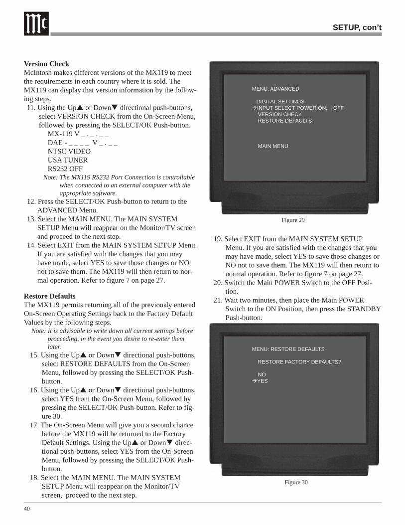
40
SETUP, con’t
Version CheckMcIntosh makes different versions of the MX119 to meetthe requirements in each country where it is sold. TheMX119 can display that version information by the follow-ing steps.11. Using the Up or Down directional push-buttons,
select VERSION CHECK from the On-Screen Menu,followed by pressing the SELECT/OK Push-button.
MX-119 V _ . _ . _ _DAE - _ _ _ _ V _ . _ _NTSC VIDEOUSA TUNERRS232 OFF
Note: The MX119 RS232 Port Connection is controllablewhen connected to an external computer with theappropriate software.
12. Press the SELECT/OK Push-button to return to theADVANCED Menu.
13. Select the MAIN MENU. The MAIN SYSTEMSETUP Menu will reappear on the Monitor/TV screenand proceed to the next step.
14. Select EXIT from the MAIN SYSTEM SETUP Menu.If you are satisfied with the changes that you mayhave made, select YES to save those changes or NOnot to save them. The MX119 will then return to nor-mal operation. Refer to figure 7 on page 27.
Restore DefaultsThe MX119 permits returning all of the previously enteredOn-Screen Operating Settings back to the Factory DefaultValues by the following steps.
Note: It is advisable to write down all current settings beforeproceeding, in the event you desire to re-enter themlater.
15. Using the Up or Down directional push-buttons,select RESTORE DEFAULTS from the On-ScreenMenu, followed by pressing the SELECT/OK Push-button.
16. Using the Up or Down directional push-buttons,select YES from the On-Screen Menu, followed bypressing the SELECT/OK Push-button. Refer to fig-ure 30.
17. The On-Screen Menu will give you a second chancebefore the MX119 will be returned to the FactoryDefault Settings. Using the Up or Down direc-tional push-buttons, select YES from the On-ScreenMenu, followed by pressing the SELECT/OK Push-button.
18. Select the MAIN MENU. The MAIN SYSTEMSETUP Menu will reappear on the Monitor/TVscreen, proceed to the next step.
19. Select EXIT from the MAIN SYSTEM SETUPMenu. If you are satisfied with the changes that youmay have made, select YES to save those changes orNO not to save them. The MX119 will then return tonormal operation. Refer to figure 7 on page 27.
20. Switch the Main POWER Switch to the OFF Posi-tion.
21. Wait two minutes, then place the Main POWERSwitch to the ON Position, then press the STANDBYPush-button.
Figure 29
MENU: ADVANCED
DIGITAL SETTINGSINPUT SELECT POWER ON: OFFVERSION CHECKRESTORE DEFAULTS
MAIN MENU
Figure 30
MENU: RESTORE DEFAULTS
RESTORE FACTORY DEFAULTS?
NOYES

41
The McIntosh MX119 has been factory configured for de-fault operating settings that will allow immediate enjoy-ment of superb video and high fidelity audio without theneed for further adjustments. If you wish to make changesto the factory default settings refer to the SETUP Sectionof this Owner’s Manual.
Power On and OffPress the POWER switch to ON, the Red Indicator abovethe STANDBY/ON Push-button lights to indicate theMX119 is in Standby Mode and the title MX-119 will ap-pear on the Front Panel Alphanumeric Display for approxi-mately two seconds. To Switch-On the MX119 press theSTANDBY/ON Push-button. During the circuitry initial-ization period (approximately four seconds) after turn-on,the Front Panel Alphanumeric Display will first indicateWARMING UP followed by the word MUTE (Audio Out-puts will be muted). Refer to figures 31, 32a and 32b.
Note: For normal operation, turn the MX119 On and Off withthe Standby/On Push-button. You may also turn On the
How to Operate the MX119MX119 by simply pressing the ON Push-button on theRemote Control. If the A/V System Controller is notgoing to be used for an extended period of time, turn Offall AC Power with the Power Switch. If the MX119 is inthe Standby Mode and is connected to a McIntoshAudio/Video Multizone Control System Controller, theFront Panel Alphanumeric Display will indicateREMOTE ZONE when any Zone of the Controller isswitched On.
Zone A Input SelectionThe INPUT Selector Switch selects the program signalsource for Zone A and is indicated on the right side of theFront Panel Alphanumeric Display. The Selection of thesource inputs for Zone A may also be accomplished bypressing the appropriate push-button on the Remote Con-trol. Refer to figure 33.
Note: If the “RC Digital Toggle” feature in setup has been setto On, an additional press of the source selection push-button on the Remote Control will allow selection ofeither the Digital or Analog Signal Source for thatassigned input. Refer to page 39 for additionalinformation.
Zone B Input SelectionFirst press the Zone B Push-button, then rotate the INPUTSelector Switch for the desired source. The selected sourceis available for Listening/Viewing in Zone B and at theAUDIO RECord OUTPUT jacks, for recording. If Zone Ais active, pressing the Zone B Push-button followed by theSTANDBY/ON Push-button will either Turn-On Zone B orTurn-Off if Zone B is already active.
Notes: About five seconds after pressing the ZONE B Push-button, the ZONE B Control Access will be switched Offand the LED above the push-button will extinguish
Figure 32a
Figure 32b
How to Operate the MX119
Figure 31
Figure 33

42
unless a Front Panel Control or Push-button is engagedafter pressing the ZONE B Push-button. Refer to “Howto Operate Zone B” on page 50.
Volume ControlAdjust the VOLUME Control to select the desired level inZone A. The Volume Control adjusts all eight channels si-multaneously, and level is indicated from 0 to 99 in thecenter of the front panel display. To change the volumelevel in Zone B when it is active, first press the Zone BPush-button and adjust the front panel VOLUME Controlto select the desired level in Zone B. The Zone B volumelevel may also be adjusted in the Zone B Room with a Re-mote Control or Keypad.
System OffNormally, Remote Zones are turned On and Off individu-ally in each respective zone by pressing the Power Push-button on a Keypad or Remote Control. If you desire toswitch Off all zones of an entire McIntosh System simulta-neously, including a control center and accessory sourcecomponents, you can press the SYS OFF Push-button onthe MX119 Front Panel. Refer to figure 34.
Note: The Sys Off Push-button on a Keypad or RemoteControl may also be used to switch Off the entiresystem.
SetupPressing the SETUP Push-button for three seconds acti-vates the MX119 SETUP Mode for making changes to theHome Theater System.
TuningThe TUNING Up and Down Push-buttons allow for
tuning to up and down the FM or AM Radio Bands whenthe optional TM1 Tuner Module is installed.
SelectWhen the MX119 has the optional TM1 Tuner Module in-stalled, the SELECT Push-button allows for selecting ei-ther the FM or AM Broadcast Bands.
EnterWhen the MX119 has the optional TM1 Tuner Module in-stalled, the ENTER Push-button is used for entering AM orFM Broadcast Stations into memory.
Preset The PRESET Left and Right Push-buttons allow forselecting the next FM or AM Radio Station that has beenstored into memory, when the optional TM1 Tuner Moduleis installed.
Late NightThe LATE NIGHT Push-button turns a volume compres-sion circuit On and Off. This feature suppresses loudsounds or music that might disturb neighbors or others notin the immediate area of the Home Theater. Soft levels arealso raised slightly so they are still listenable at reducedoverall volume levels. This works only on a Dolby DigitalSound Track with encoded data that supports the compres-sion function.
Reset of MicroprocessorsIn the event that the controls of the MX119 stop function-ing, there is a built-in user reset function. Press thePOWER Switch to OFF and wait for two minutes. Then
Figure 34

43
Press the POWER Switch to ON. This will reset theMX119 microprocessors. Refer to figure 33 on page 41.Note: The above condition is usually caused by either
interruptions in AC power and/or major changes involtage.
Front Panel StatusThe front panel LEDs indicate the status of Operating/De-coding Modes. Refer to figure 34.
Operating Mode DisplaysA. The DOLBY DIGITAL Display will illuminate when
the input contains Dolby Digital Encoded Signals.B. The EX (Dolby Digital) Display will illuminate
when the input contains Dolby Digital EX EncodedSignals.
C. The PRO LOGIC IIx Display will illuminate whenthe Surround Mode Selector is turned to CINEMA1or MUSIC 1 positions.
D. The DIGITAL SIGNAL Display will illuminatewhen the MX119 is processing a Digital EncodedSignal.
E. The DTS Display will illuminate when the input con-tains DTS Encoded Signals.
F. The DTS ES Display will illuminate when the inputcontains DTS ES Encoded Signals.
G. The NEO:6 Display will illuminate when the Sur-round Mode Selector is turned to CINEMA2 or MU-SIC 2 positions.
H. The 2 CHANNEL Display will illuminate when theSurround Mode Selector is turned to STEREO (2CHANNEL) position.
How to Operate the MX119, con’t

44
How to Operate the Trim ModeThe MX119 TRIM SELECT Switch together with theTRIM LEVEL Control provide the means for adjustingseven different audio functions and the Front Panel Alpha-numeric Display Brightness. This can be accomplishedfrom either the Front Panel Controls or with the suppliedRemote Control, very conveniently from the Listening/Viewing Area. The Front Panel Alphanumeric Display indi-cates the Trim Mode Selected and Trim Levels. You cancreate the sound quality that you prefer while listening tomusic or a movie sound track. Refer to figures 37 & 39.
Note: The following Trim Examples are performed using theMX119 Front Panel Controls. They also can be madeusing the supplied Remote Control. Make any TrimAdjustments based on your own preferences.
Loudspeaker Volume LevelsThe Volume Levels of the Center, Subwoofer and SurroundLoudspeakers can be adjusted up or down by 12dB relativeto the Left and Right Front Loudspeakers and saved in per-manent memory for the Stereo, Music (1 - 4) and ExternalSurround Modes. They are automatically recalled any timethat particular input is selected again.The Surround Trimlevel adjustments made in CINEMA 1 and CINEMA 2 willrevert back to the Setup Loudspeaker Levels when theMX119 is placed in STANDBY (Off).
1. Rotate the TRIM SELECT Control to theSUBWOOFER position and SUB TRIM appears onthe Front Panel Alphanumeric Display. Refer to figure37.
Note: Low Frequency Information must be present in theProgram Source Material in order to hear anychanges in the Subwoofer Loudspeaker Levels.
2. Press the Front Panel TRIM LEVEL Up or DownPush-button until the number 5 appears to the right ofSUB TRIM on the Front Panel Alphanumeric Display.This is an example of increasing the Subwoofer levelby 5dB.
3. Rotate the TRIM SELECT Control to the SURR SPKRposition and SURR TRIM appears on the Front Panel
Figure 38
Figure 40
Figure 37
Figure 39
Alphanu-mericDisplay.Refer tofigure 38.
4. Press theFrontPanelTRIMLEVELUp or Down Push-button until the number -10 ap-pears to the right of SURR TRIM on the display. Thisis an example of decreasing the Surround Loud-speakers Levels by 10dB.
5. Rotate the TRIM SELECT Control to the CENTERSPKR position and CTR TRIM appears on the FrontPanel Alphanumeric Display. Refer to figure 40.
6. Press the Front Panel TRIM LEVEL Up or DownPush-button until the number 3 appears to the right ofCTR TRIM on the Front Panel Alphanumeric Display.This is an example of increasing the Center Loud-speaker Level by 3dB.
Notes: 1. If no Trim adjustments are made during a tensecond interval, the TRIM Mode will becancelled and the normal Front Panel Displaywill appear.
2. The location of the Trim Selector Control willremain in the last selected position until theINPUT A Listen Control or SURROUND MODEControl is changed.
Bass and TrebleThe MX119 allows for changing the tonal response for anyof the eight inputs via the BASS and TREBLE Compensa-tion TRIM Adjustments. Any tonal changes made are savedin permanent memory and automatically recalled any timethat particular input is selected again. The Bass and TrebleTonal Response can be adjusted up or down by 12db fromthe Flat Setting.
1. Rotate the TRIM SELECT Control clockwise untilBASS TRIM appears on the Front Panel AlphanumericDisplay. Refer to figure 41.
2. Press the Front Panel TRIM LEVEL Up or DownPush-button until the number 10 appears to the right of

45
BASS TRIM on the Front Panel Alphanumeric Dis-play. This is an example of increasing the Bass re-sponse by 10dB.
3. Rotate the TRIM SELECT Control clockwise untilTREB TRIM appears on the Front Panel AlphanumericDisplay. Refer to figure 42.
4. Press the Front Panel TRIM LEVEL Up or DownPush-button until the number 11 appears to the right ofTREB on the Front Panel Alphanumeric Display. Thisis an example of increasing the Treble response by11dB.
EffectsThe MX119’s Trim Select Effect Mode allows for differenttypes of audio signal processing as different SurroundModes are selected. Refer to the chart below:
LoudnessThe Loudness Control Function automatically increasesbass response as the volume level is lowered for improved
Figure 41
Figure 42
Figure 43
Figure 44
Figure 45
listening at softer volume levels. The amount of LoudnessBoost is adjustable in 10% increments from 10% to 100%.The maximum Loudness boost is 18dB, less any bass boostthat may have been previously set by the Bass Trim func-tion. For example if the Bass is boosted 10dB, the maxi-mum additional Loudness boost will be 18dB less 10dB or8dB. Refer to figure 43.
1. Rotate the TRIM SELECT Control clockwise to theEFFECT position. The word TRIMLOUD will appearon the Front Panel Alphanumeric Display.
2. Press the Front Panel TRIM LEVEL Up or DownPush-button until the desired percent of Loudness isindicated to the right of TRIMLOUD on the FrontPanel Alphanumeric Display.
Center WidthThis mode takes some of the Center Channel Signal andadds it to the Left and Right Front Loudspeakers, thus in-creasing the width of the front sound field. The effect canbe varied with eight different settings ranging from mini-mum (0) to maximum (7). Refer to figures 44 and 45.
3. Rotate the TRIM SELECT Control clockwise to theEFFECT position. The words CTR WIDTH will ap-pear on the Front Panel Alphanumeric Display.
4. Press the Front Panel TRIM LEVEL Up or DownPush-button until the desired sound stage is achieved.
EffectWhen the MUSIC 4 Surround Mode is selected, the EF-FECT Mode allows for various alterations to the SoundStage.
5. Rotate the TRIM SELECT Control clockwise to theEFFECT position. The word EFFECT together with a
How to Operate the Trim Mode
Surround Mode Effect Sound Type
Stereo Loudness Compensation
Cinema 1 Loudness Compensation
Cinema 2 Loudness Compensation
External Loudness Compensation
Music 1* Center Width
Music 2** Center Width
Music 4 Sound Stage Variations
Trim Effect Mode
*when a two channel signal is processed in the aDolby Pro Logic IIx Mode
**when a two channel signal is processed in the aaDTS NEO:6 Mode

46
Figure 47
number will appear on the Front Panel AlphanumericDisplay. Refer to figure 46.
6. Press the Front Panel TRIM LEVEL Up or DownPush-button to select one of the many different soundeffects available.
Display BrightnessThe brightness of the Front Panel Alphanumeric Displaymay be adjusted using the Display Trim Feature. The Dis-play brightness range extends from Off to a maximumbrightness setting of 31.
1. Rotate the TRIM SELECT Control clockwise untilDISPLAY appears on the Front Panel AlphanumericDisplay. A number to the right of the display indicatesthe current brightness level. Refer to figure 47.
2. Press the Front Panel TRIM LEVEL Up or DownPush-button until the desired display brightness isachieved.
How to Operate the Trim Mode, con’t
Figure 46

47
Figure 51
The MX119 provides nine different Surround Modes. TheFront Panel Alphanumeric Display and the Output FormatLEDs will indicate the Surround Mode selected. The Sur-round Mode Selected is stored into permanent memory andautomatically recalled any time that particular input is se-lected again. If the Surround Mode is changed when theinput is again selected, thenew mode will be activeand stored. Refer to figure48.
Note: The Remote Controlmay also be used tomake changes to theSurround Modes.
Stereo ModeA Stereo signal source connected to an Analog Audio Inputis reproduced without any processing. The Front Panel Al-phanumeric Display will indicate PURE STEREO. When aDigital Audio Input is selected in Stereo Mode, the FrontPanel Alphanumeric Display will indicate DSP STEREO.All multichannel signal sources are combined and reducedto 2 channels in the stereo mode. Refer to figures 49 and50.
Music 1The Front Panel Alphanumeric Display will indicate MU-SIC 1. Refer to figure 51. This Mode utilizes Dolby ProLogic II Processing to create a wide and deep sound space.The effect may be varied depending upon the Trim EffectSetting for “Center Width”, refer to page 45 to alter the set-tings.
Music 2The Front Panel Alphanumeric Display will indicate MU-SIC 2. Refer to figure 52. This Mode utilizes DTS NEO:6Processing to add center, surround and back channels to a
Figure 53
Figure 52
stereo recording. The effect may be varied depending uponthe Trim Effect Setting for “Center Width”, refer to page 44to alter the settings.
Music 3The Front Panel Alphanumeric Display will indicate MU-SIC 3. Refer to figure 53. This processing Mode creates aneffect of a party in a small room. A Center Channel andBack Surround Channel are created from the sum of theLeft and Right Front Channels. The Left and Right FrontChannel Information is also sent to the Surround Loud-speakers.
Note: The Music 3 Surround Mode is intended for use withtwo channels of audio information.
Music 4The Front Panel Alphanumeric Display will indicate MU-SIC 4. Refer to figure 54. This processing Mode creates aneffect of a Night Club. A Center Channel is created fromthe Left and Right Front Channels. The Left and RightFront Channels are processed through the Trim Effect andsent to the Surround Loudspeakers. Refer to page 45 to al-ter the Trim Effect settings.
Note: The Music 4 Surround Mode is intended for use withtwo channels of audio information.
Cinema 1The Front Panel Alphanumeric Display will indicate CIN-EMA 1 and the appropriate Front Panel Operating ModeDisplay LEDs will illuminate. Refer to figure 55 on page48. This provides Dolby Pro Logic IIx processing of Ana-log Signals and 2-Channel Digital Signals.
When a Dolby Digital or DTS Signal is present theMX119 will automatically decode the information either asMono, Stereo, Surround or 5.1 discrete depending on theinformation contained in the signal. If a 5.1 signal containsback surround information (Dolby Digital EX or DTS ES/
Figure 54
How to Operate the Surround Mode
How to Operate the Surround Mode
Figure 48
Figure 49
Figure 50

48
EX), the decoder will reproduce all 7.1 channels of infor-mation.
Cinema 2The Front Panel Alphanumeric Display will indicate CIN-EMA 2 and the appropriate Front Panel Operating ModeDisplay LEDs will illuminate. Refer to figure 56. This pro-vides DTS NEO:6 processing Analog Signals and 2-Chan-nel Digital Signals.
When a Dolby Digital or DTS Digital Signal is presentthe MX119 will automatically decode the information ei-ther as Mono, Stereo or Surround depending on the infor-mation contained in the signal. If the signal contains 5.1 ormore channels of information, the decoder will automati-cally reproduced the signal as 7.1 channels of information.
ExternalAll internal signal processing is bypassed and the eightRear Panel EXTERNAL INPUTS are activated so theMX119 performs as an Eight Channel Preamplifier for anexternal source or processor. The Front Panel Alphanu-meric Display indicates EXTERNAL. Refer to figure 57a.
Note: Approximately 3 seconds after selecting EXTERNALSURROUND MODE, the Front Panel AlphanumericDisplay will change, indicating EXTERNAL, to thenormal display of INPUT A, INPUT B and percentageof VOLUME.
Dobly Digital Pro Logic IIx Music ModeThe MX119’s built-in Dolby Digital Prologic IIx MusicProcessing Mode allows for the adjustment of the depth(Dimension), width (Center Width) and spread (Panorama)of the sound when the MUSIC 1 Surround Mode is se-lected. Refer to figure 48 on page 47.
Note: The Front Panel Alphanumeric Display will indicateany changes made to the Dolby Digital Prologic IIMusic Processing Mode.
Figure 57a
How to Operate the Surround Mode, con’t
Figure 55
Figure 56
Pro Logic IIx PanoramaThis mode adds Surround Sound by spreading the soundfield of the front speakers to the left and right of the listen-ing position. This effect can be switched On or Off. Referto figures 57b and 57c.1. Using the Remote Control, press the HOME Push-but-
ton followed by immediately pressing the SELECTpush-button to switch the Panorama effect On or Off.
Pro Logic IIx Center WidthThis mode takes some of the Center Channel Signal andadds it to the Left and Right Front Loudspeakers, thus in-creasing the width of the front sound field. The effect canbe varied with eight different settings ranging from mini-mum (0) to maximum (7). Refer to figures 44 and 45 onpage 45.2. Using the Remote Control, press the HOME Push-but-
ton followed by pressing immediately the Left orRight directional push-buttons to select the desiredeffect.
Pro Logic IIx DimensionThis mode allows for adjusting the balance between theFront and Surround Sound Fields. The effect can be variedwith seven different settings ranging from -3 to +3. Referto figures 57d and 57e.3. Using the Remote Control, press the HOME Push-but-
ton followed by pressing immediately the Up orDown directional push-buttons select the desired ef-fect.
Figure 57e
Figure 57d
Figure 57c
Figure 57b
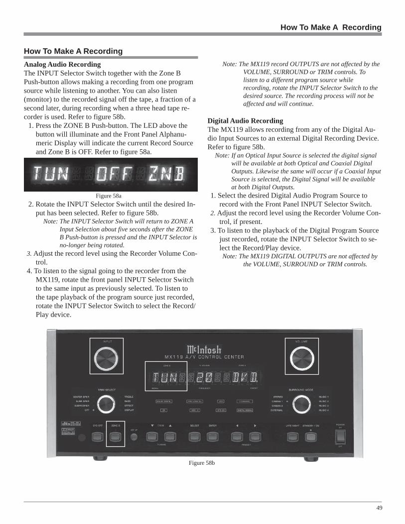
49
How To Make A RecordingAnalog Audio RecordingThe INPUT Selector Switch together with the Zone BPush-button allows making a recording from one programsource while listening to another. You can also listen(monitor) to the recorded signal off the tape, a fraction of asecond later, during recording when a three head tape re-corder is used. Refer to figure 58b.
1. Press the ZONE B Push-button. The LED above thebutton will illuminate and the Front Panel Alphanu-meric Display will indicate the current Record Sourceand Zone B is OFF. Refer to figure 58a.
2. Rotate the INPUT Selector Switch until the desired In-put has been selected. Refer to figure 58b.
Note: The INPUT Selector Switch will return to ZONE AInput Selection about five seconds after the ZONEB Push-button is pressed and the INPUT Selector isno-longer being rotated.
3. Adjust the record level using the Recorder Volume Con-trol.
4. To listen to the signal going to the recorder from theMX119, rotate the front panel INPUT Selector Switchto the same input as previously selected. To listen tothe tape playback of the program source just recorded,rotate the INPUT Selector Switch to select the Record/Play device.
How To Make A Recording
Note: The MX119 record OUTPUTS are not affected by theVOLUME, SURROUND or TRIM controls. Tolisten to a different program source whilerecording, rotate the INPUT Selector Switch to thedesired source. The recording process will not beaffected and will continue.
Digital Audio RecordingThe MX119 allows recording from any of the Digital Au-dio Input Sources to an external Digital Recording Device.Refer to figure 58b.
Note: If an Optical Input Source is selected the digital signalwill be available at both Optical and Coaxial DigitalOutputs. Likewise the same will occur if a Coaxial InputSource is selected, the Digital Signal will be availableat both Digital Outputs.
1. Select the desired Digital Audio Program Source torecord with the Front Panel INPUT Selector Switch.
2. Adjust the record level using the Recorder Volume Con-trol, if present.
3. To listen to the playback of the Digital Program Sourcejust recorded, rotate the INPUT Selector Switch to se-lect the Record/Play device.Note: The MX119 DIGITAL OUTPUTS are not affected by
the VOLUME, SURROUND or TRIM controls.
Figure 58b
Figure 58a

50
Operating Zone B from a Keypad or SensorTo activate Zone B Control from the Keypad or Sensor per-form the following steps. Refer to figure 61.
1. Press the POWER Push-button on the Keypad or usethe Remote Control aimed at a Sensor located in ZoneB.
Note: When Zone B is switched On the MX119 FrontPanel Alphanumeric Display will indicate ZONE BON, if Zone A is not active.
2. Select the desired Zone B Source and adjust the Vol-ume to the desired listening level by pressing the ap-propriate push-buttons on the Keypad or Remote Con-trol.
3. If a McIntosh Disc Player is connected to the MX119,most operating functions can be performed with theKeypad or Remote Control.
Note: By adding a McIntosh Remote Control Translatorto the MX119, non McIntosh Source Devices, suchas a Satellite Receiver, can be remotely controlledusing a McIntosh Remote Control and Keypads.
Controlling a Source Component from Zone BTo control a source component from the Keypad or Sensorperform the following steps. Refer to figure 61.
1. Press the appropriate source push-button (e.g. CD) onthe Keypad or Remote Control. Then press the appro-priate control push-button for the desired function (e.g.the Next Push-button to play the next selectionfrom the disc).
Figure 61
How to Operate Zone BThe MX119 includes the capability of being able to operateand control two audio/video zones, independently of eachother. Zone A is the Primary (Home Theater ListeningArea) with Surround Sound. Zone B is configured for aSecondary Remote Location providing two channel audioand video programs.
The MX119 Front Panel Alphanumeric Display indi-cates the Zone A Program Source Selected on the right sideand the Zone B Program Source Selected on the left side.Refer to figure 58b on page 49.
Operating Zone B from the MX119 Front PanelTo activate Zone B Control from the MX119 Front Panel,perform the following steps.
1. Press the Front Panel STANDBY/ON Push-button, ifZone A is not active.
2. Press the ZONE B Push-button and immediately pressthe STANDBY/ON Push-button, the Front Panel Al-phanumeric Display will indicate Zone B Input SourceSelect and Volume Level. Refer to figure 59.
Note: During the time the LED Indicator above the ZONEB Push-button is illuminated (approximately threeseconds), the Zone B Volume Level may be changedusing the VOLUME Control. The Zone B Powermay also be switched Off by pressing the FrontPanel STANDBY/ON Push-button within the threesecond time period. If the Front Panel Controlreverts back to Zone A (the LED Indicator abovethe ZONE B Push-button is not illuminated), pressthe ZONE B Push-button again to activate controlof Zone B.
3. Rotate the INPUT Selector Switch to select the desiredsource.
4. Press the ZONE B Push-button and then rotate theVOLUME Control to the desired volume level forZone B.
5. To switch Off Zone B from the MX119 Front Panel ifZone A is already Off, press the SYS OFF Push-button.Refer to figure 58b on page 49.
Figure 60
Figure 59
How to Operate Zone B

51
General Specifications
Frequency ResponseLeft, Center, Right,Left Surround,Right Surround,Left Back, Right Back:±0.5dB from 20Hz-20,000Hz
Subwoofer1:±0.5dB from 20Hz-140Hz
Total Harmonic Distortion0.005% maximum from 20Hz to 20,000Hz at rated output
Signal To Noise RatioPhono: 86dB below 10mV input (A Weighted)High Level: 96dB below rated output (A Weighted)
Rated Output Voltage2.5V Unbalanced Outputs (Main)5.0V Balanced Outputs (Main)
Maximum Voltage Output9.5V Unbalanced19V Balanced
Output Impedance100 ohms Unbalanced200 ohms Balanced
Input ImpedancePhono: 47k Ohms, 65pfHigh Level: 22k Ohms Unbalanced
50k Ohms Balanced
Sensitivity for Rated OutputPhono: 5mVHigh Level: 500mV Unbalanced
1V Balanced
Maximum Input SignalPhono: 50mVHigh Level: 5V Unbalanced
10V Balanced
Voltage GainPhono to REC Out: 40dBPhono to Output (Main): 54dBHigh Level to REC Out: 0dBHigh Level to Output (Main): 14dB
Tone ControlsBass Control: ±12dB at 30HzTreble Control: ±12dB at 10,000Hz
Power Requirements100 Volts, 50/60Hz at 65 watts110 Volts, 50/60Hz at 65 watts120 Volts, 50/60Hz at 65 watts220 Volts, 50/60Hz at 65 watts230 Volts, 50/60Hz at 65 watts240 Volts, 50/60Hz at 65 wattsNote: Refer to the rear panel of the MX119 for the correct
voltage.
Overall DimensionsWidth is 17-1/2 inches (44.45cm)Height is 7-5/8 inches (19.37cm) including feetDepth is 18-3/4 inches (47.63cm) including the Front Paneland Knobs
Weight27 pounds (12.25Kg) net, 46 pounds (20.87Kg) shipping
Audio and General Specifications
Audio Specifications
1 If any of the Channels have the Loudspeaker Setting of Small, thesubwoofer has an electronic low pass filter with a 24dB per Octaverolloff in all modes except external.

52
McIntosh RAA1Remote AM Antenna
Cable for connecting theRAA1 to the MX119
Cables for installingthe McIntosh TM1AM/FM Tuner Moduleinto the MX119
High PerformanceMcIntosh AM/FMTuner Module
TM1 AM/FM Tuner Module
••••• Special FM RF AmplifierDouble-Diffused Metal Oxide Field Effect Transistor(DMOS-FET) RF amplifier increases sensitivity and CrossModulation rejection.
••••• External AM RF Amplifier and AntennaThe TM1 includes a RAA1 Remote AM Antenna that con-tains an electrostatically shielded AM RF Amplifier Stagefor maximum noise rejection. It can be located in a remotearea, away from sources of interference and can be posi-tioned for the best possible reception of even the weakestAM stations.
••••• FM Stereo Auto Blend CircuitryAn automatic variable stereo separation control circuit isused to reduce background noise when receiving weak ste-reo stations.
••••• Preset Stations and Permanent MemoryNine AM and nine FM station presets make it easy to listento your favorite stations. Station Presets and FunctionsModes are retained in Permanent Memory even when ACpower is switched Off.
••••• Alphanumeric Fluorescent DisplayThe MX119 Multi-function Front Panel Display indicatesstation frequency, station preset number, signal strength,stereo and broadcast band.
Performance Features
The MX119 A/V Control Center has provisions for addingan optional McIntosh TM1 AM/FM Tuner Module for Ra-dio Station Reception. The TM1 delivers the same excep-tional performance as the stand-alone McIntosh MR85Tuner. The TM1 is available from your McIntosh Dealerand can be installed at any time, usually while you wait.
Introduction
TM1 Table of ContentsIntroduction ..................................................................... 52Performance Features ...................................................... 52MX119 Rear and RAA1 Top PanelsAntenna Connections ....................................................... 53How to Connect Antenna Components ........................... 54How to Operate the Tuner ............................................... 55How to Assign Preset Stations ......................................... 56How to Optimize AM Reception ..................................... 57FM Specifications ............................................................ 58AM Specifications ........................................................... 58

53
MX119 Rear Panel and RAA1 Top Panel Antenna Connections
75 OHM FM ANT(Antenna) connectsto an external FMAntenna or cable
AM ANT (An-tenna) connectorallows a McIntoshRemote Antenna tobe connected
RAA1 Remote Antenna can be adjusted to aposition for optimum reception of your fa-vorite AM stations
Connects withsupplied cable tothe MX119
Note: Proceed to page 13and start theconnection process.

54
How to Connect Antenna Components
FM Antenna
1. Connect the Remote AM Antenna by plugging the DINConnector of the supplied 3 conductor cable into theAM ANTenna, DIN socket on the back panel of theMX119.
Note: If a longer length cable needs to be used between theMX119 and the RAA1, use a 2 conductor shielded cable.
2. Connect a 75 ohm coax cable from an FM Antenna orcable system to the MX119, 75 OHM FM ANTennaConnector.
3. Proceed to page 19 and continue the connection pro-cess.
How to Connect Antenna ComponentsRAA1 ConnectorConnect the shield and two leadsof a shielded 2 conductor cable tothe supplied 5 Pin Terminal Con-nector Plug. Refer to the connec-tion information on the top coverof the RAA1.
7 Pin DIN Connector1. Red Wire 5. N/C2. Black Wire 6. Jumper from Pin 73. N/C 7. Green Wire (Shield)4. N/C and Jumper to Pin 6
RedBlack
Green
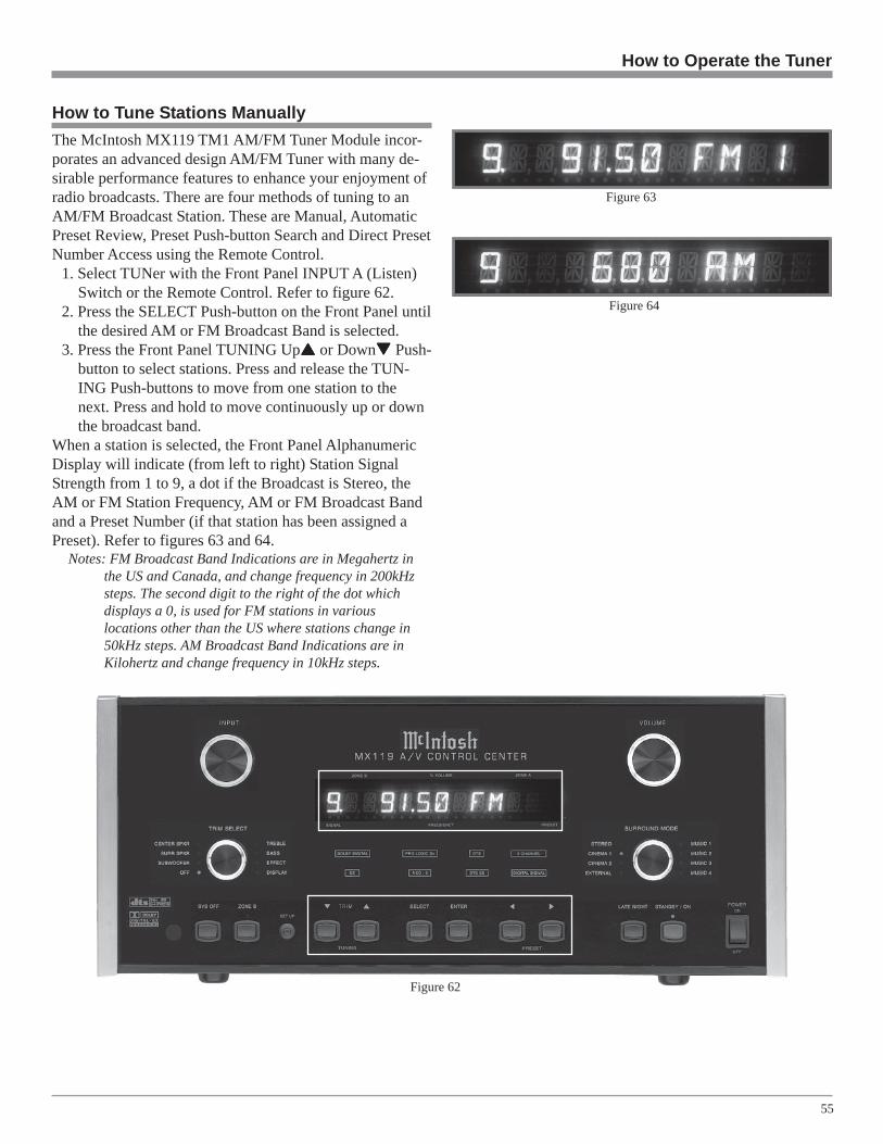
55
How to Operate the Tuner
How to Tune Stations ManuallyThe McIntosh MX119 TM1 AM/FM Tuner Module incor-porates an advanced design AM/FM Tuner with many de-sirable performance features to enhance your enjoyment ofradio broadcasts. There are four methods of tuning to anAM/FM Broadcast Station. These are Manual, AutomaticPreset Review, Preset Push-button Search and Direct PresetNumber Access using the Remote Control.
1. Select TUNer with the Front Panel INPUT A (Listen)Switch or the Remote Control. Refer to figure 62.
2. Press the SELECT Push-button on the Front Panel untilthe desired AM or FM Broadcast Band is selected.
3. Press the Front Panel TUNING Up or Down Push-button to select stations. Press and release the TUN-ING Push-buttons to move from one station to thenext. Press and hold to move continuously up or downthe broadcast band.
When a station is selected, the Front Panel AlphanumericDisplay will indicate (from left to right) Station SignalStrength from 1 to 9, a dot if the Broadcast is Stereo, theAM or FM Station Frequency, AM or FM Broadcast Bandand a Preset Number (if that station has been assigned aPreset). Refer to figures 63 and 64.
Notes: FM Broadcast Band Indications are in Megahertz inthe US and Canada, and change frequency in 200kHzsteps. The second digit to the right of the dot whichdisplays a 0, is used for FM stations in variouslocations other than the US where stations change in50kHz steps. AM Broadcast Band Indications are inKilohertz and change frequency in 10kHz steps.
Figure 62
Figure 63
Figure 64

56
How To Clear an Assigned Station Preset
1. Press ENTER Push-button.2. Press the Front Panel PRESET Left and Right
Push-buttons to select the Preset Station that will beremoved from memory.
3. Press and Hold the ENTER Push-button for approxi-mately 3 seconds until the Front Panel AlphanumericDisplay indicates the word CLEARED. Refer to figure68.Note: If you wish to replace an already assigned Station
Preset with another radio station, it is not necessaryto clear the Preset first, just enter in the new stationfor that Preset. The new station will automaticallyreplace the previously assigned station.
4. To clear any additional Station Presets perform steps 1through 3 again.
How to Assign Preset Stations
The MX119 AM/FM Tuner Module (TM1) allows for pre-setting radio stations into memory. To enter Presets followthe below steps:
Note: If there are no Presets Assigned and either the FrontPanel PRESET Push-buttons or the Remote ControlREVIEW Push-button are pressed, the MX119 FrontPanel Alphanumeric Display will indicate NOPRESETS. Refer to figure 65.
1. Select either the AM or FM Broadcast Band.2. Press the Front Panel TUNING Up or Down Push-
button to select a station.3. Momentarily press and release the Front Panel ENTER
Push-button. The Front Panel Alphanumeric Displaywill indicate 1 AVAILABLE, which is the first of 9Preset Numbers that can be assigned. The Station thatis about to be entered into memory may also assignedto a different Preset Number (2-9) by pressing thePRESET Left and Right Push-buttons to select thedesired Preset Number. Refer to figure 66.Note: Presets are automatically assigned in order from 1 to
9 unless a different Preset Number is selected.
4. Press and release the Front Panel ENTER Push-button asecond time to store the Preset into memory. The justentered Station Preset Selection will be assigned PresetNumber 1 which is displayed on the far right side ofthe Front Panel Alphanumeric. Refer to figure 67.
5. Assign additional station Presets by performing steps 1through 5 until a total of 9 AM and 9 FM Station Pre-sets have been assigned. Each time you assign an addi-tional Preset Number, the Front Panel AlphanumericDisplay will indicate the number of the next availablePreset.Note: If all 9 Presets are assigned and the ENTER Push-
button is pressed, the display will indicate the stationselected for Preset Number 1.
How to Assign Preset Stations
6. To verify the Station Preset(s) just entered intomemory, press the PRESET Left and Right Push-buttons to cycle through and confirm your preset as-signments.
Figure 65
Figure 66
Figure 67
Figure 68

57
The McIntosh RAA1 Remote AM Antenna is designed toprovide the best in AM Reception especially if the tuner orA/V unit is located in a noisy reception area. Locate theRAA1 away from all electronic and electrical interferencesources. Rotate the AM Antenna to reduce interference andreceive maximum signal strength.
Notes: The RAAI Remote AM Antenna of the TM1 has beenfactory adjusted for optimum reception in a typicalurban location. If you wish to customize the AMAntenna for the best possible performance in yourlocation, have your dealer perform the two adjustmentoperationslisted below.An additionallong wire AMantenna orexternalground can beconnected tothe GND andANT terminalsif desired.
1. Tune to a weakAM station near600kHz on the AM band. Using an appropriate NON -
How to Optimize AM Reception
Figure 69
METALLIC tool, adjust the 600kHz Transformer L1for maximum signal strength. Refer to figure 69.
2. Tune to a weak AM station near 1400kHz on the AMband. Using an appropriate NON - METALLIC tool,adjust the 1400kHz Trimmer Capacitor C1 for maxi-mum signal strength.
3. Repeat steps 1 and 2 until no further improvements canbe obtained.
How to Optimize AM Reception
Preset Number Frequency City Call Letters Name
FM 1FM 2FM 3FM 4FM 5FM 6FM 7FM 8FM 9AM 1AM 2AM 3AM 4AM 5AM 6AM 7AM 8AM 9
FM and AM Station Presets

58
FM Tuner SpecificationsUseable Sensitivity14dBf which is 1.4uV across 75 ohms
50dB Quieting SensitivityMono: 19dBf which is 2.4uV across 75 ohmsStereo: 35dBf which is 15uV across 75 ohms
Signal To Noise RatioMono: 75dBStereo: 70dB
Frequency ResponseMono: + 0, - 1dB from 20 to 15,000HzStereo: + 0, - 1dB from 20 to 15,000Hz
Harmonic DistortionMono: 0.3% at 100Hz
0.3% at 1,000Hz0.3% at 10,000Hz
Stereo: 0.45% at 100Hz0.45% at 1,000Hz0.65% at 10,000Hz
Intermodulation DistortionMono 0.25%Stereo 0.45%
Capture Ratio1.2dB
Alternate Channel Selectivity75dB
Spurious Response100dB
Image Response75dB
RF Intermodulation65dB
Stereo Separation45dB at 100Hz45dB at 1,000Hz35dB at 10,000Hz
SCA Rejection65dB
TM1 FM and AM Specifications
AM Tuner SpecificationsSensitivity20uV External Antenna Input
Signal To Noise Ratio48dB at 30% modulation58dB at 100% modulation
Harmonic Distortion0.5% maximum at 50% modulation
Frequency Response50Hz to 6kHz NRSC
Adjacent Channel Selectivity45dB minimum IHF
Image Rejection65dB minimum from 540 to 1600kHz
IF Rejection80dB minimum
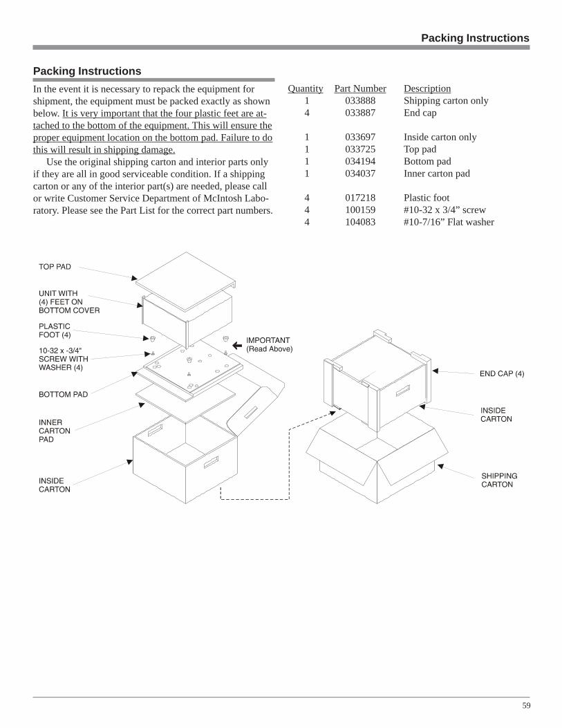
59
Packing InstructionsIn the event it is necessary to repack the equipment forshipment, the equipment must be packed exactly as shownbelow. It is very important that the four plastic feet are at-tached to the bottom of the equipment. This will ensure theproper equipment location on the bottom pad. Failure to dothis will result in shipping damage.
Use the original shipping carton and interior parts onlyif they are all in good serviceable condition. If a shippingcarton or any of the interior part(s) are needed, please callor write Customer Service Department of McIntosh Labo-ratory. Please see the Part List for the correct part numbers.
Packing Instructions
Quantity Part Number Description1 033888 Shipping carton only4 033887 End cap
1 033697 Inside carton only1 033725 Top pad1 034194 Bottom pad1 034037 Inner carton pad
4 017218 Plastic foot4 100159 #10-32 x 3/4” screw4 104083 #10-7/16” Flat washer

McIntosh Part No. 04090400
McIntosh Laboratory, Inc.2 Chambers Street
Binghamton, NY 13903
The continuous improvement of its products isthe policy of McIntosh Laboratory Incorporatedwho reserve the right to improve design withoutnotice.
Printed in the U.S.A.