auxetic metamaterials under direct impact loads in a ... · notional embedded structural health...
TRANSCRIPT

Auxetic Metamaterials under Direct Impact Loads in a
Structural Health Monitoring Framework
by James Ayers, Ben Chamish, Tzi-Kang Chen, Anindya Ghoshal, Chandan
Kittur, Michael Coatney, Natasha Bradley, and Tyrone Jones
ARL-TR-6306 January 2013
Approved for public release; distribution unlimited.

NOTICES
Disclaimers
The findings in this report are not to be construed as an official Department of the Army position
unless so designated by other authorized documents.
Citation of manufacturer’s or trade names does not constitute an official endorsement or
approval of the use thereof.
Destroy this report when it is no longer needed. Do not return it to the originator.

Army Research Laboratory Aberdeen Proving Ground, MD 21005
ARL-TR-6306 January 2013
Auxetic Metamaterials under Direct Impact Loads in a
Structural Health Monitoring Framework
James Ayers, Tzi-Kang Chen, Anindya Ghoshal, Chandan Kittur,
Michael Coatney, and Natasha Bradley Vehicle Technology Directorate, ARL
Ben Chamish and Tyrone Jones Weapons and Materials Research Directorate, ARL
Approved for public release; distribution unlimited.

ii
REPORT DOCUMENTATION PAGE Form Approved OMB No. 0704-0188
Public reporting burden for this collection of information is estimated to average 1 hour per response, including the time for reviewing instructions, searching existing data sources, gathering and maintaining the
data needed, and completing and reviewing the collection information. Send comments regarding this burden estimate or any other aspect of this collection of information, including suggestions for reducing the
burden, to Department of Defense, Washington Headquarters Services, Directorate for Information Operations and Reports (0704-0188), 1215 Jefferson Davis Highway, Suite 1204, Arlington, VA 22202-4302.
Respondents should be aware that notwithstanding any other provision of law, no person shall be subject to any penalty for failing to comply with a collection of information if it does not display a currently valid
OMB control number.
PLEASE DO NOT RETURN YOUR FORM TO THE ABOVE ADDRESS.
1. REPORT DATE (DD-MM-YYYY)
January 2013
2. REPORT TYPE
Final
3. DATES COVERED (From - To)
1 October 2011 to 30 September 2012 4. TITLE AND SUBTITLE
Auxetic Metamaterials under Direct Impact Loads in a Structural Health
Monitoring Framework
5a. CONTRACT NUMBER
5b. GRANT NUMBER
5c. PROGRAM ELEMENT NUMBER
6. AUTHOR(S)
James Ayers, Ben Chamish, Tzi-Kang Chen, Anindya Ghoshal, Chandan Kittur,
Michael Coatney, Natasha Bradley, and Tyrone Jones
5d. PROJECT NUMBER
5e. TASK NUMBER
5f. WORK UNIT NUMBER
7. PERFORMING ORGANIZATION NAME(S) AND ADDRESS(ES)
U.S. Army Research Laboratory
ATTN: RDRL-VTM
Aberdeen Proving Ground, MD 21005
8. PERFORMING ORGANIZATION REPORT NUMBER
ARL-TR-6306
9. SPONSORING/MONITORING AGENCY NAME(S) AND ADDRESS(ES)
10. SPONSOR/MONITOR’S ACRONYM(S)
11. SPONSOR/MONITOR’S REPORT NUMBER(S)
12. DISTRIBUTION/AVAILABILITY STATEMENT
Approved for public release; distribution unlimited.
13. SUPPLEMENTARY NOTES
14. ABSTRACT
Under direct impact from ballistic loads, acoustic waves typically propagate throughout a structural component causing damage
to sensitive areas. For structures with intelligent embedded monitoring systems, such as mounted piezoelectric actuators, a
direct impact between 150–200 m/s of small-caliber rounds has produced catastrophic results. This report focuses on
redirecting acoustic waves using non-traditional structural configurations. The technical approach utilizes periodic and graded
metamaterials (produced from auxetic cellular, lattice topology and material composition), which are lightweight and can be
assembled for extreme anisotropy and phononic bandgaps, which can be exploited to alter the propagation path of high
amplitude stress waves. This research focuses on the initial stage of understanding how to tailor periodic lattices for highly
concentrated impact and blast loads, which generally produce a broadband frequency response and yield only partial bandgaps.
Specific attention is given to square, hexagonal, re-entrant, and modified re-entrant topologies. As a baseline comparison, a
solid aluminum plate is examined against uniform and graded re-entrant unit cell lattices. The plates are individually subjected
to both in- and out-of-plane direct impact loading conditions of a 0.22-caliber fragment simulating projectile traveling at
300 m/s. A less than 10% marginal difference in peak stress amplitude exists between the loading conditions for a given single
through-the-thickness unit cell. 15. SUBJECT TERMS
Auxetic, metamaterials, lattice, impact
16. SECURITY CLASSIFICATION OF: 17. LIMITATION OF ABSTRACT
UU
18. NUMBER OF PAGES
26
19a. NAME OF RESPONSIBLE PERSON
James Ayers a. REPORT
Unclassified
b. ABSTRACT
Unclassified
c. THIS PAGE
Unclassified
19b. TELEPHONE NUMBER (Include area code)
410-278-7650
Standard Form 298 (Rev. 8/98)
Prescribed by ANSI Std. Z39.18

iii
Contents
List of Figures iv
List of Tables iv
1. Background and Motivation 1
2. Objectives and Technical Approach 3
3. Numerical Analysis 3
3.1 Numerical Setup ..............................................................................................................4
3.2 Numerical Results ...........................................................................................................7
3.2.1 Full-field Wave Propagation ...............................................................................7
3.2.2 In-plane Loading Quantitative Comparison ......................................................11
3.3.3 Out-of-plane Loading Quantitative Comparison ...............................................13
4. Experimental Investigation 14
4.1 Experimental Setup .......................................................................................................14
4.2 Experimental Results .....................................................................................................15
5. Conclusions 16
6. References 18
List of Symbols, Abbreviations, and Acronyms 19
Distribution List 20

iv
List of Figures
Figure 1. Notional embedded structural health monitoring system for impact. .............................1
Figure 2. Finite element method (FEM) parameterization: (a) Hexagonal honeycomb (angle θ = 30°), (b) rectangular cell (angle θ = 0°), (c) re-entrant cell (angle θ = –10°), (d) hexagonal cell with linear variation of the cell thickness in Z direction, (e) hexagonal cell with gradual variation in X-Y plane, and (f) re-entrant cell with banded thick wall regions. .......................................................................................................................................4
Figure 3. (a) View of projectile (green)-lattice (magenta) interface and (b) magnified view. .......5
Figure 4. Loading conditions: (a) in-plane impact and (b) out of plane impact of the FSP impacting the periodic lattice. ....................................................................................................6
Figure 5. Loading profile: (a) time domain and (b) frequency content. .........................................6
Figure 6. Comparison of time history of wave propagation for in-plane loading: (a) solid plate, (b) uniform auxetic lattice, and (c) graded T-banded auxetic lattice. ..............................8
Figure 7. Comparison of time history of wave propagation for out-of-plane loading: (a) solid plate, (b) uniform auxetic lattice, and (c) graded T-banded auxetic lattice. ..........................10
Figure 8. Identified monitoring locations for (a) in-plane and (b) out-of-plane load. ..................11
Figure 9. In-plane loading comparison per spatial location for uniform auxetic lattice: (a) radial alignment and (b) vertically aligned points. .............................................................12
Figure 10. In-plane loading solid versus auxetic lattice configuration: (a) point 4 and (b) point 8. ................................................................................................................................12
Figure 11. Out-of-plane loading comparison per spatial location: (a) radial and (b) vertical points. .......................................................................................................................................13
Figure 12. Out-of-plane loading solid vs. lattice configuration: (a) point 4 and (b) point 8. ......14
Figure 13. Auxetic panel: (a) schematic and (b) plexiglass panel with bonded piezoelectric actuator. ....................................................................................................................................15
Figure 14. Auxetic panel subjected to continuous harmonic loads: excitation frequency at (a) 35 kHz and (b) 65 kHz. .....................................................................................................16
List of Tables
Table 1. Monitoring point location relative to an origin (0,0) at lower left corner. .....................11

1
1. Background and Motivation
Under direct impact from ballistic loads, acoustic waves will typically propagate throughout a
structural component and may cause damage to sensitive areas. Sensitive areas may be defined
as primary structural elements (PSE) that are critical for mission performance, i.e., embedded
hardware such as avionic controlling devices or intelligent systems that allow for structural state
awareness (figure 1). For structures with intelligent embedded monitoring systems, such as
mounted piezoelectric actuators, a direct impact between 150–200 m/s of small-caliber rounds
has produced catastrophic results (1). One way to reduce the wave propagation is to design a
larger structure, which lowers the resulting localized stress, while increasing undesirable weight.
Another design strategy is to guide the waves away from the critical areas by built-in energy
arresters or lightweight structured materials. Air-based vehicles, such as airplanes and
helicopters, generally require the weight to be minimized for range and endurance. This report
focuses on redirecting guided waves using non-traditional structural configurations that are
conventionally lightweight.
Figure 1. Notional embedded structural health monitoring system for impact.
Traditional passive armor platforms operate under two stages during a small arms ballistic event:
(1) arresting the projectile and (2) energy dissipation. Extensive armor research has focused on
ceramic materials, which are some of the most efficient armor materials to mitigate momentum

2
transfer of a small- or medium-caliber projectile (2). Ceramic recipes rely on stiffness from
backing materials to work on arresting the projectile. These backing materials are usually bonded
behind ceramics with low-density, low-impedance, and low shear strength adhesives. The
backing is largely used to dissipate the kinetic energy in a ceramic armor system. As an example,
experimental and modeling methods have been developed to investigate mechanical responses
on sandwich composite panels subjected to the impact of explosively driven wet sand (3). Under
high-intensity dynamic loading, sandwich panels suffered 30% less deflection than equivalent
solid plates. One-dimensional studies were used to study the momentum and energy transfer to
plates in air blasts (4).
Other work investigated the dynamic behavior of two types of sandwich composites composed
of E-Glass Vinyl-Ester (EVE) face sheets and Corecell™ A-series foam with a polyurea
interlayer (5). Using a shock tube apparatus to subject samples to high-intensity impulse loading,
results show that the addition of polyurea interlayer improves the overall blast performance and
maintains structural integrity. However, ceramic armor concepts can suffer due to parasitic
weight. One method of reducing the energy is by redirecting a significant portion of the energy,
i.e., shock waves, as the projectile impacts the armor, which improves the ballistic performance
of passive armor systems (6). It is expected that the understanding and development of novel
dynamic energy dissipation mechanisms for armor systems under high ballistic loading rates will
forge the development of new and possibly improved solutions for protection (7).
Metamaterial research is an emerging area due to recent advances in additive manufacturing and
has been broadly defined as materials that have properties associated with the structure as
opposed to their inherent chemical composition. One researched metamaterial is a periodic
lattice, which has the distinct structural advantage of redundancy for load paths and contact
interface. One such periodic lattice is the auxetic configuration, which is characterized by a
negative Poisson’s ratio, where the lattice exhibits a dilatation under tensile loads and contraction
under compressive loads. Continuous periodic structures with a cell structure smaller than a
desired wavelength will attenuate and guide waves (8). Unit cells with negative internal angles
have shown to reduce the angular range of wave propagation (9). In addition, auxetic topologies
with angles between –30° and 30° have shown to propagate waves primarily in the vertical
direction. The negative internal angle has the added benefit of having significantly less
propagation in the horizontal direction. There is also a change in the directionality depending on
the frequency of the excitation.
Other work focused on in-plane wave propagation in chiral lattices using Bloch analysis, with
sets of parameters that affect the elasto-dynamic behavior, suggesting a class of lattice for
designing novel photonic metamaterials (10). Periodicity has been exploited with resistive
inductive (RL) shunted piezoelectric patches to control vibrations of a cantilever aluminum plate
(11). Results indicate that the unit cell approach can predict the actual response of the system.

3
The auxetic lattice also exhibits anisotropy, which means a dependence on direction. Since the
acoustic waves must follow a path along the structure, the energy is diverted in the path of least
resistance. Functionally graded materials (FGMs) have been modeled to investigate propagation
of large amplitude waves within layered and graded structures. Results illustrate that it involves
complex coupling of elastic and viscoelastic responses (12).
2. Objectives and Technical Approach
The primary objective of this research is to understand how waves propagate in inorganic
materials under direct impact loads. A secondary goal is to develop optimized structures that
distribute energy and stress levels to specified locations. The approach is to utilize the
anisotropic behavior of auxetic periodic lattices to redirect the energy, and then to fabricate and
test the metamaterials under prescribed loading conditions that are parallel and perpendicular to
the periodicity of the lattice. The developed configurations are evaluated against a baseline
configuration, which is a simplified metallic plate.
3. Numerical Analysis
The models of three-dimensional (3-D) lattice structures are generated for finite element analysis
using solid continuum elements. In order to build and update the structures models with different
shape, size, and details of the cell, the models were generated using Abaqus/CAE with plug-in
Python codes that generate the models with different parametric features. The following features
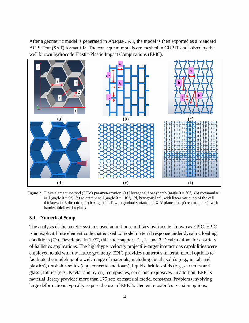
were designed for variation, as shown in figure 2:
1. Model geometric dimensions: (X, Y, Z)
2. Shape of the unit cell (hexagon, rectangular, re-entrant)
3. Angles of the cell (θ)
4. Sizes of the unit cell (a, h)
5. Wall thickness in the unit cell (t1, t2)
6. Linear variation of the cell wall thickness in model thickness direction (Z)
7. Variation of the cell wall thickness in model X-Y plane (gradually or banded)
4
After a geometric model is generated in Abaqus/CAE, the model is then exported as a Standard
ACIS Text (SAT) format file. The consequent models are meshed in CUBIT and solved by the
well known hydrocode Elastic-Plastic Impact Computations (EPIC).
(a) (b) (c)
(d) (e) (f)
Figure 2. Finite element method (FEM) parameterization: (a) Hexagonal honeycomb (angle θ = 30°), (b) rectangular
cell (angle θ = 0°), (c) re-entrant cell (angle θ = –10°), (d) hexagonal cell with linear variation of the cell
thickness in Z direction, (e) hexagonal cell with gradual variation in X-Y plane, and (f) re-entrant cell with
banded thick wall regions.
3.1 Numerical Setup
The analysis of the auxetic systems used an in-house military hydrocode, known as EPIC. EPIC
is an explicit finite element code that is used to model material response under dynamic loading
conditions (13). Developed in 1977, this code supports 1-, 2-, and 3-D calculations for a variety
of ballistics applications. The high/hyper velocity projectile-target interactions capabilities were
employed to aid with the lattice geometry. EPIC provides numerous material model options to
facilitate the modeling of a wide range of materials, including ductile solids (e.g., metals and
plastics), crushable solids (e.g., concrete and foam), liquids, brittle solids (e.g., ceramics and
glass), fabrics (e.g., Kevlar and nylon), composites, soils, and explosives. In addition, EPIC’s
material library provides more than 175 sets of material model constants. Problems involving
large deformations typically require the use of EPIC’s element erosion/conversion options,
5
wherein finite elements are either eroded (eliminated) or converted to particles when their
inelastic strains have exceeded a user-specified threshold level. EPIC’s Generalized Particle
Algorithm (GPA) is used to model the behavior of the converted particles. The solid model
geometries discussed in section 3 were created in Abaqus/CAE then meshed externally with the
software CUBIT. The meshed model was then transferred to the EPIC software. The
discretization of auxetic panels was high enough to necessitate parallel processing, and the
models were solved using EPIC on eight processors.
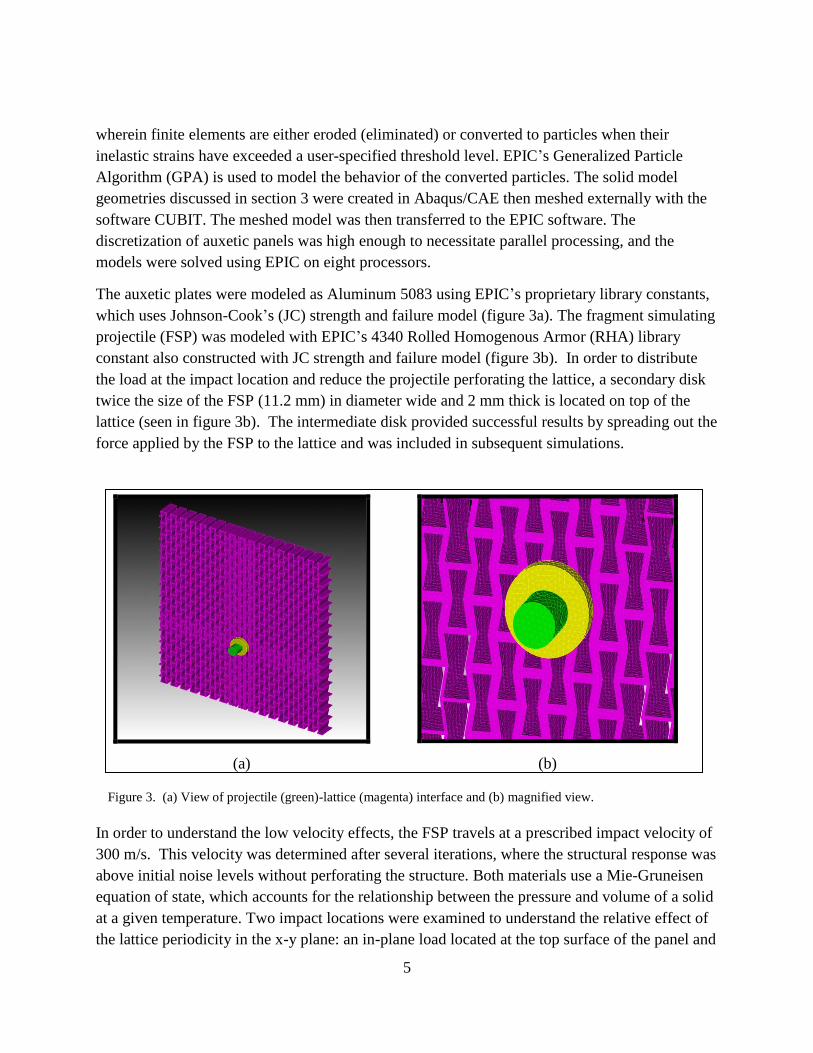
The auxetic plates were modeled as Aluminum 5083 using EPIC’s proprietary library constants,
which uses Johnson-Cook’s (JC) strength and failure model (figure 3a). The fragment simulating
projectile (FSP) was modeled with EPIC’s 4340 Rolled Homogenous Armor (RHA) library
constant also constructed with JC strength and failure model (figure 3b). In order to distribute
the load at the impact location and reduce the projectile perforating the lattice, a secondary disk
twice the size of the FSP (11.2 mm) in diameter wide and 2 mm thick is located on top of the
lattice (seen in figure 3b). The intermediate disk provided successful results by spreading out the
force applied by the FSP to the lattice and was included in subsequent simulations.
(a) (b)
Figure 3. (a) View of projectile (green)-lattice (magenta) interface and (b) magnified view.
In order to understand the low velocity effects, the FSP travels at a prescribed impact velocity of
300 m/s. This velocity was determined after several iterations, where the structural response was
above initial noise levels without perforating the structure. Both materials use a Mie-Gruneisen
equation of state, which accounts for the relationship between the pressure and volume of a solid
at a given temperature. Two impact locations were examined to understand the relative effect of
the lattice periodicity in the x-y plane: an in-plane load located at the top surface of the panel and

6
an out-of-plane load whose impact was located where the T-banded horizontal and vertically
graded unit cells intersect (figure 4).
(a) (b)
Figure 4. Loading conditions: (a) in-plane impact and (b) out of plane impact of the FSP impacting the periodic lattice.
The primary purpose of the loading study is to understand how the stress waves travel to exploit
the in-plane periodicity and answer the fundamental question whether out-of-plane loading may
be successfully directed by a periodic panel in the in-plane direction.
The loading profile from the impact was determined by summing the nodal forces at the point of
impact throughout the time interval in which the load rapidly decays. The temporal and spectral
profiles are provided in figure 5a–b. It can be seen that for the given FPS, the primary frequency
lobe is between 10‒50 kHz, which will be a consideration later in the design of the unit cell size
and respective geometry selection per reference 9.
(a) (b)
Figure 5. Loading profile: (a) time domain and (b) frequency content.

7
3.2 Numerical Results
Full-field wave propagation effects and single point analysis are compared for given plate
configurations and loading conditions. A qualitative study of the wave propagation is performed
on three different plate configurations. A quantitative study of individual points on the plates
relative to the impact load is then provided.
3.2.1 Full-field Wave Propagation
As a qualitative comparison of the stress wave interaction within the periodic configurations,
figure 6a–c shows sequential progression at 20 µs intervals of three different plate
configurations: a solid aluminum plate, a homogeneous plate with a re-entrant unit cell, and a T-
banded graded plate with a re-entrant unit cell. For comparative purposes, each plate was
designed with equivalent mass, where the length and width spatial dimensions were fixed, while
the depth of each configuration is varied.

8
Figure 6. Comparison of time history of wave propagation for in-plane loading: (a) solid plate, (b) uniform
auxetic lattice, and (c) graded T-banded auxetic lattice.
(a) (b) (c)

9
Qualitatively, from figure 6a, the solid plate exhibits radial waves, which are then reflected at the
boundaries and a complex interaction exists between the incident and reflected waves after the
40-µs time interval. The uniform and graded T-banded auxetic panels illustrate the apparent
vertical anisotropic behavior of the panels, where the maximum stress field is clearly vertically
oriented, particularly in the figure 6c. Rather than radial waves, this observed redirection of the
energy is possible for in-plane impact loading due to the inherent in-plane unit cell periodicity. In
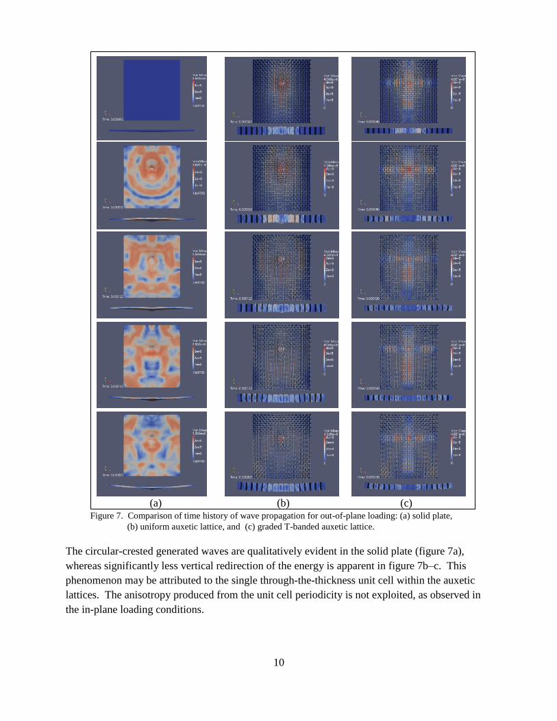
contrast, figure 7a–c depicts the solid and auxetic plates under out-of-plane loading at the 80-µs
interval, such that the axis of the FSP is perpendicular to the mid-plane of the plate.
10
Figure 7. Comparison of time history of wave propagation for out-of-plane loading: (a) solid plate,
(b) uniform auxetic lattice, and (c) graded T-banded auxetic lattice.
The circular-crested generated waves are qualitatively evident in the solid plate (figure 7a),
whereas significantly less vertical redirection of the energy is apparent in figure 7b–c. This
phenomenon may be attributed to the single through-the-thickness unit cell within the auxetic
lattices. The anisotropy produced from the unit cell periodicity is not exploited, as observed in
the in-plane loading conditions.
(a) (b) (c)

11
3.2.2 In-plane Loading Quantitative Comparison
For in-plane loading, the plates were monitored at specific locations to more fully understand the
effect of the auxetic lattice, consequent grading effects, and the dependence on the loading
direction. Figure 8 identifies the eight monitoring points, and table 1 provides the (x,y) locations
relative to the origin at the lower left corner. Eight points were identified for each plate
configuration: four radially aligned (numbered 1–4) and four vertically aligned (numbered 5–8).
(a) (b)
Figure 8. Identified monitoring locations for (a) in-plane and (b) out-of-plane load.
The monitoring points (table 1) were spatially identical for each plate configuration, solid and
auxetic, for subsequent quantitative comparisons.
Table 1. Monitoring point location relative to an origin (0,0) at lower left corner.
Point X [mm] Y [mm]
1 32 52
2 25 44
3 19 36
4 12 28
5 55 52
6 55 36
7 55 20
8 55 4
Figure 9a–b compares the radial and vertically aligned points as a function time and von Mises
stress for the uniform auxetic lattice.
X
Y
X
Y

12
(a) (b)
Figure 9. In-plane loading comparison per spatial location for uniform auxetic lattice: (a) radial alignment and
(b) vertically aligned points.
From figure 9a–b, it is observed that the maximum Von Mises stress occurs at Points 1 and 5,
which is expected due to their proximity to the impact location. For the radially aligned points,
the relative peak stress is reduced by 62.5% from Point 1 to Point 4, which is approximately
equivalent to the vertically aligned stress reduction of 64.5% from Point 5 to Point 8. Potential
reasons for the dramatic reduction are wave attenuation through material damping, boundary
interaction, and distribution of the energy through the periodic ligaments.
A comparison between the solid, uniform auxetic, and graded auxetic are shown for selected
points in figure 10a–b.
(a) (b)
Figure 10. In-plane loading solid vs. auxetic lattice configuration: (a) point 4 and (b) point 8.

13
From figure 10a, the incident arrival time of the wave is a factor of 2.9 faster in the solid plate
than the auxetic lattice at radial Point 4, and a factor of 1.9 larger in peak stress amplitude. This
significant discrepancy highlights the effectiveness of the auxetic lattices to directionally orient
the energy per the designed anisotropy of unit cell. In figure 10b, the initial arrival time of the
solid plate is 9.2% faster than the auxetic configurations at the vertical Point 8, whereas the
initial peak amplitude decreases by 36.3%. These results further confirm the premise that the
energy is steered vertically as the loading remains in-plane to the periodicity, while the wave
speeds are approximately equivalent.
3.3.3 Out-of-plane Loading Quantitative Comparison
The identical eight monitoring points are compared for out-of-plane loading conditions, as
shown in figure 8b. Figure 11 presents a comparison of the uniform auxetic lattice for the radial
and vertical points, and gives specific attention to comparing the solid to auxetic lattice
configuration.
(a) (b)
Figure 11. Out-of-plane loading comparison per spatial location: (a) radial and (b) vertical points.
From figure 11a, the peak amplitude ratio is an estimated 3:1 ratio of radial locations Point 1 and
Point 4, whereas the peak amplitude of the vertical locations Points 5‒7 are within 5%. The
distinct variation between the radial and vertical points may be attributed to anisotropy of the
auxetic lattice configuration. Figure 12a–b illustrates the solid to lattice variation as a function of
time for Point 4 and Point 8.
14
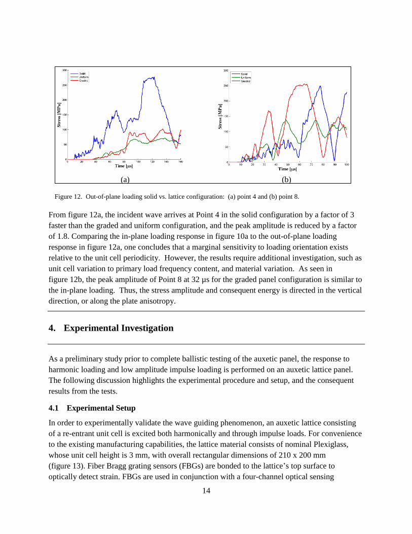
(a) (b)
Figure 12. Out-of-plane loading solid vs. lattice configuration: (a) point 4 and (b) point 8.
From figure 12a, the incident wave arrives at Point 4 in the solid configuration by a factor of 3
faster than the graded and uniform configuration, and the peak amplitude is reduced by a factor
of 1.8. Comparing the in-plane loading response in figure 10a to the out-of-plane loading
response in figure 12a, one concludes that a marginal sensitivity to loading orientation exists
relative to the unit cell periodicity. However, the results require additional investigation, such as
unit cell variation to primary load frequency content, and material variation. As seen in
figure 12b, the peak amplitude of Point 8 at 32 µs for the graded panel configuration is similar to
the in-plane loading. Thus, the stress amplitude and consequent energy is directed in the vertical
direction, or along the plate anisotropy.
4. Experimental Investigation
As a preliminary study prior to complete ballistic testing of the auxetic panel, the response to
harmonic loading and low amplitude impulse loading is performed on an auxetic lattice panel.
The following discussion highlights the experimental procedure and setup, and the consequent
results from the tests.
4.1 Experimental Setup
In order to experimentally validate the wave guiding phenomenon, an auxetic lattice consisting
of a re-entrant unit cell is excited both harmonically and through impulse loads. For convenience
to the existing manufacturing capabilities, the lattice material consists of nominal Plexiglass,
whose unit cell height is 3 mm, with overall rectangular dimensions of 210 x 200 mm
(figure 13). Fiber Bragg grating sensors (FBGs) are bonded to the lattice’s top surface to
optically detect strain. FBGs are used in conjunction with a four-channel optical sensing

15
interrogator, an si920 purchased from MicronOptics, Inc. The si920 has a maximum sampling
rate of 500 kS/s for a single channel, or a 120 kS/s. By pulsing a light through the fiber, an
internal algorithm within the si920 converts the change in wavelength from the FBG to a
calibrated strain.
Figure 13a–b shows the experimental setup of the Plexiglass lattice. Two FBGs are placed along
the vertical Y-axis where the primary incident wave is expected to propagate. Two additional
FBGs are located radially at 45° from the actuator, where the propagation is expected to be
significantly less. In the harmonic loading testing, the lattice is excited using a piezoelectric
actuator, which operates by converting voltage into mechanical strain. The piezoelectric actuator
is driven by an input sine function from am Agilent 3320A wave generator. The amplitude is
kept constant, and a frequency sweep from 10 to 120 kHz is performed to evaluate the structural
response. The optical interrogator is triggered by the wave generator, such that the strain
measurements as a function of time and frequency may be recorded.
(a) (b)
Figure 13. Auxetic panel: (a) schematic and (b) plexiglass panel with bonded piezoelectric actuator.
4.2 Experimental Results
The strain amplitudes of the auxetic lattice for different frequencies at Sensors 1 and 2 are shown
in figure 14. The strain ratio from Sensor 1 to 2 varies by 3.8:1 and 17:1 for frequencies 35 and
65 kHz, respectively. The significant amplitude decrease in figure 14a–b may be attributed to the
attenuation produced by the material damping of the composite and the anisotropy from the unit
cell orientation.

16
(a) (b)
Figure 14. Auxetic panel subjected to continuous harmonic loads: excitation frequency at (a) 35 kHz and
(b) 65 kHz.
5. Conclusions
Several conclusions may be derived from the numerical and experimental investigation.
Numerically, the full-field results demonstrated the ability to steer energy for both in- and out-of-
plane low velocity impact loading conditions. It was expected that in-plane periodicity would
enable more efficient steering when subjected to in-plane impact relative to the baseline of a
solid aluminum plate. However, only a marginal sensitivity to loading orientation exists relative
to the unit cell periodicity, as the out-of-plane loading exhibited a calculated 10% decrease to in-
plane loading. In addition, the incident arrival time of the wave is a factor of 2.9 faster in the
solid plate than the auxetic lattice, and a factor of 1.9 larger in peak stress amplitude. This
significant discrepancy highlights the effectiveness of the auxetic lattices to directionally orient
the energy per the designed anisotropy of unit cell. Experimentally, a large amplitude differential
from vertical to radial directivity may be attributed to the attenuation produced by the material
damping of the composite and the anisotropy from the unit cell orientation. However, these
numerical results require additional investigation, such as unit cell variation to primary load
frequency content, and material variation.
Furthermore, future work consists of higher fidelity experiments that enable decoupling of the
waves and to sweep higher frequency regimes, such that an accurate mapping of the wave
guiding phenomenon is achieved. Instrumentation such as Digital Image Correlation (DIC) and
3-D laser Doppler vibrometry will allow for increased resolution of the stress wave. Additional
testing using an impulse hammer experiment will be used to investigate low energy levels. Other
considerations must include the ligament to ligament connection and related instabilities, such as

17
plasticity zones near the joints. A preliminary study of standing waves within individual
ligaments and potential for energy cancelation mechanisms is underway. An extension of the
work will consider the design, fabrication, and testing of 3-D lattice-wise periodic graded panels
to explore through-thickness wave redirection. A 3-D lattice-wise system may allow for internal
structural health monitoring and increase the design space for the lattice configuration as
multifunctional configuration as a self-sensing, adaptive system for direct impact loads.

18
6. References
1. Salamone, S.; Bartoli, I.; Rhymer, J.; Lanza di Scalea, F.; Kim, H. Validation of the
Piezoelectric Rosette Technique for Locating Impacts in Complex Aerospace Panels. Proc.
SPIE 2011, 7984, 79841E.
2. Anderson Jr., C. E.; Burkins, M. S.; Walker, J. D.; Gooch, W. A. Time-Resolved
Penetration of B4C Tiles by the APM2 Bullet. Computer Modeling in Engineering &
Sciences 2005, 8 (2), 91–104.
3. Rimoli, J. J.; Talamini, B.; Wetzel, J. J.; Dharmasena K. P.; Radovitzky, R.; Wadley, H.N.G.
Wet-sand Impulse Loading of Metallic Plates and Corrugated Core Sandwich Panels.
International Journal of Impact Engineering 2011, 38, 837–848.
4. Hutchinson J. W. Energy and Momentum Transfer in Air Shocks. Journal of Applied
Mechanics 2009, 76 (5), 051307-1–051307-7.
5. Gardner, N.; Wang, E.; Kumar, P.; Shulka, A. Blast Mitigation in a Sandwich Composite
Using Graded Core and Polyurea. Experimental Mechanics 2011, 52, 119–133.
6. Walker, J. Turning Bullets into Baseballs. Technology Today 1887, 17–21.
7. Kataev, I. G. Electromagnetic Shock Waves. Iliffe, ISBN: 0592050017, 1966.
8. Langley, R. S. The Response of Two-dimensional Periodic Structures to Point Harmonic
Loading. J. Sound Vibration 1996, 197 (4), 447–469.
9. Ruzzene, M.; Scarpa, F. Directional and Band-gap Behavior of Periodic Auxetic Lattices.
Physica Status Solidi (B), Applied Research 2005, 242 (3), 665–680.
10. Spadoni A. Application of Chiral Cellular Materials for the Design of Innovative
Components. Ph.D. Thesis, Georgia Institute of Technology, 2008.
11. Casadei, F.; Ruzzene, M.; Dozio, L.; Cunefare, K. A. Broadband Vibration Control Through
Periodic Arrays of Resonant Shunts: Experimental Investigation on Plates. Smart Materials
and Structures I 2010, 19 (1), 1–13.
12. Li, Y.; Ramesh, K. T.; Chin, E.S.C. Dynamic Characterization of Layered and Graded
Structures Under Impulsive Loading. International Journal of Solids and Structures 2001,
38 (34–35), 6045–6061.
13. Johnson, G. R.; Beissel, S. R.; Gerlach, C. A.; Holmquist, T. J User Instructions for the
2011 Version of the EPIC Code; Final Report; Southwest Research Institute, TX, 2011.

19
List of Symbols, Abbreviations, and Acronyms
3-D three-dimensional
DIC Digital Image Correlation
EPIC Elastic-Plastic Impact Computations
EVE E-Glass Vinyl-Ester
FBGs fiber Bragg grating
FGMs functionally graded materials
FEM finite element method
FSP fragment simulating projectile
GPA Generalized Particle Algorithm
JC Johnson-Cook’s
PSE primary structural elements
RHA rolled homogenous armor
RL resistive inductive
SAT standard ACIS Text

20
NO. OF
COPIES ORGANIZATION
1 DEFENSE TECHNICAL
(PDF INFORMATION CTR
only) DTIC OCA
8725 JOHN J KINGMAN RD
STE 0944
FORT BELVOIR VA 22060-6218
1 PDF DIRECTOR
US ARMY RESEARCH LAB
IMAL HRA
2800 POWDER MILL RD
ADELPHI MD 20783-1197
1 PDF DIRECTOR
US ARMY RESEARCH LAB
RDRL CIO LL
2800 POWDER MILL RD
ADELPHI MD 20783-1197
ABERDEEN PROVING GROUND
6 HCS US ARMY RESEARCH LAB
ATTN RDRL VTM
J AYERS
A GHOSHAL
T CHEN
M COATNEY
N BRADLEY
D LE
APG MD 21005
2 HCS US ARMY RESEARCH LAB
ATTN RDRL WMP E
B CHAMISH
T JONES
APG MD 21005
TOTAL: 11 (3 PDF, 8 HCS)