autopilot navpilot-611 - furuno usa · lever type: fap-6221, 6222 dodge type: fap-6231, 6232...
TRANSCRIPT
www.furuno.co.jp
AUTOPILOT NAVpilot-611
Installation Manual TABLE OF CONTENTS
SAFETY INSTRUCTIONS.......................i
SYSTEM CONFIGURATION.................. ii
EQUIPMENT LISTS .............................. iii
1. INSTALLATION OF UNITS .......... 1-1 1.1 Control Unit FAP-6011..................... 1-1 1.2 Processor Unit FAP-5002................ 1-3 1.3 Rudder Reference Unit FAP-6112 ... 1-4 1.4 Remote Controllers (option) ............ 1-5
2. WIRING ....................................... 2-1 2.1 Wiring System................................. 2-1 2.2 Processor Unit................................. 2-2 2.3 Control Unit ..................................... 2-7 2.4 Remote Controllers (option) ............ 2-8 2.5 Connection of Instruments FI-30 ... 2-11 2.6 Input/Output Sentences................. 2-12
3. ADJUSTMENTS........................... 3-1 3.1 How to Access the Installation Menu.... ....................................................... 3-1 3.2 DOCKSIDE SETUP Menu .............. 3-2 3.3 SEA TRIAL Menu...........................3-11 3.4 DISPLAY SETUP Menu ................ 3-16 3.5 DATA CALIBRATION Menu........... 3-18 3.6 Other Settings............................... 3-20
PACKING LISTS.................................A-1
OUTLINE DRAWINGS ..................... D-1
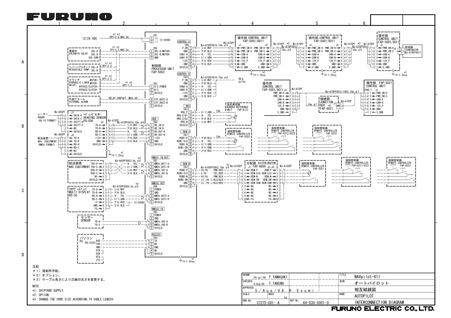
INTERCONNECTION DIAGRAMS ...S-1

The paper used in this manualis elemental chlorine free.
・FURUNO Authorized Distributor/Dealer
9-52 Ashihara-cho,Nishinomiya, 662-8580, JAPAN
Telephone : +81-(0)798-65-2111
Fax : +81-(0)798-65-4200
A : AUG 2008.Printed in JapanAll rights reserved.
Pub. No. IME-72750-A
*00016935610**00016935610*(HIMA ) NAVPILOT-611*00016935610**00016935610** 0 0 0 1 6 9 3 5 6 1 0 *

i
WARNINGTurn off the power at the switchboardbefore beginning the installation.
Fire or electrical shock can result if thepower is left on.
Use the specified power cable.
Use of other power cable may result infire.
CAUTION
Observe the following compass safedistances to prevent interference to amagnetic compass:
Control unit
Standard Steeringcompass compass
0.30 m 0.30 m
Confirm that the power supply voltageis compatible with the voltage rating of the equipment.
Connection to the wrong power supplycan cause fire or equipment damage.
Processorunit
0.35 m 0.30 m
SAFETY INSTRUCTIONS
Remotecontrollers 0.30 m 0.30 m
Confirm that no one is near the rudderwhen bleeding air from oil cylinder.
The rudder may move unexpectedly,possibly causing bodily injury.
When connecting a geomagnetism detection type heading sensor, correct magnetic field deviation.
If an autopilot is used without the compen-sation, unexpected course change may occur.
Set REMOTE CONTROLLER 1 and 2 on SYSTEM SETUP menu properly accord-ing to remote controller connected.
If not done properly, malfunction may occur. Especially, take care when setting the NFU-type remote controller.

ii
SYSTEM CONFIGURATION
Standard configuration is shown with solid line.
12-24 VDC
Processor UnitFAP-5002
Control UnitFAP-6011 (Max. 6)*
Heading sensorPG-500
Rudder Reference UnitFAP-6112
Remote Controller
Distributor FAP-6800
Remote Controller
Remote Controller
Reversible pump orElectromagnetic valve unit
PC
External buzzer
Navigator(NMEA0183)
RD-30 (Max. 3)(NMEA0183)
Clutch
Remote Controller
Remote controlerDial type: FAP-5551, FAP-5552Button type: FAP6211, FAP-6212Lever type: FAP-6221, 6222Dodge type: FAP-6231, 6232
Ship's steering system
*: Any combination of FAP-5001, 5011 and 6011 is available. Also, FAP-5021 can be connected at the end of series.
iii
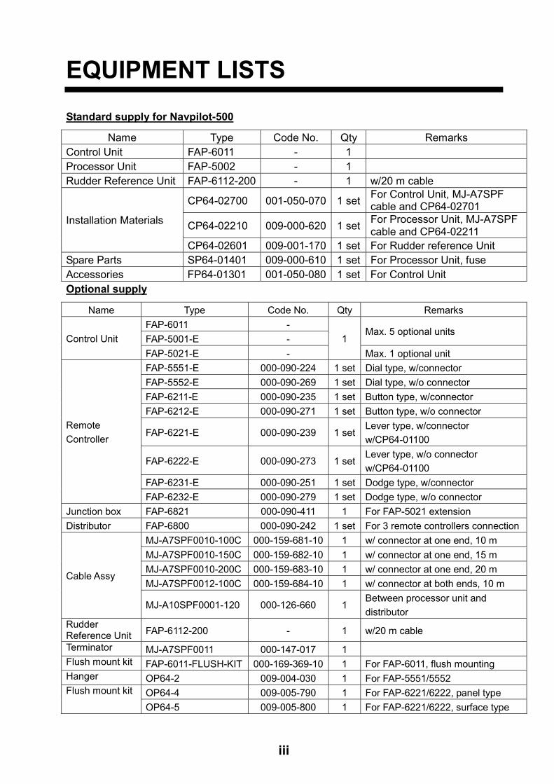
EQUIPMENT LISTS
Standard supply for Navpilot-500
Name Type Code No. Qty Remarks Control Unit FAP-6011 - 1 Processor Unit FAP-5002 - 1 Rudder Reference Unit FAP-6112-200 - 1 w/20 m cable
CP64-02700 001-050-070 1 set For Control Unit, MJ-A7SPF cable and CP64-02701
CP64-02210 009-000-620 1 set For Processor Unit, MJ-A7SPF cable and CP64-02211
Installation Materials
CP64-02601 009-001-170 1 set For Rudder reference Unit Spare Parts SP64-01401 009-000-610 1 set For Processor Unit, fuse Accessories FP64-01301 001-050-080 1 set For Control Unit Optional supply
Name Type Code No. Qty Remarks FAP-6011 - FAP-5001-E -
Max. 5 optional units Control Unit
FAP-5021-E - 1
Max. 1 optional unit FAP-5551-E 000-090-224 1 set Dial type, w/connector FAP-5552-E 000-090-269 1 set Dial type, w/o connector FAP-6211-E 000-090-235 1 set Button type, w/connector FAP-6212-E 000-090-271 1 set Button type, w/o connector
FAP-6221-E 000-090-239 1 setLever type, w/connector w/CP64-01100
FAP-6222-E 000-090-273 1 setLever type, w/o connector w/CP64-01100
FAP-6231-E 000-090-251 1 set Dodge type, w/connector
Remote Controller
FAP-6232-E 000-090-279 1 set Dodge type, w/o connector Junction box FAP-6821 000-090-411 1 For FAP-5021 extension Distributor FAP-6800 000-090-242 1 set For 3 remote controllers connection
MJ-A7SPF0010-100C 000-159-681-10 1 w/ connector at one end, 10 m MJ-A7SPF0010-150C 000-159-682-10 1 w/ connector at one end, 15 m MJ-A7SPF0010-200C 000-159-683-10 1 w/ connector at one end, 20 m MJ-A7SPF0012-100C 000-159-684-10 1 w/ connector at both ends, 10 m
Cable Assy
MJ-A10SPF0001-120 000-126-660 1 Between processor unit and distributor
Rudder Reference Unit FAP-6112-200 - 1 w/20 m cable
Terminator MJ-A7SPF0011 000-147-017 1 Flush mount kit FAP-6011-FLUSH-KIT 000-169-369-10 1 For FAP-6011, flush mounting Hanger OP64-2 009-004-030 1 For FAP-5551/5552
OP64-4 009-005-790 1 For FAP-6221/6222, panel type Flush mount kit
OP64-5 009-005-800 1 For FAP-6221/6222, surface type

iv
This page is intentionally left blank.
1-1
1. INSTALLATION OF UNITS
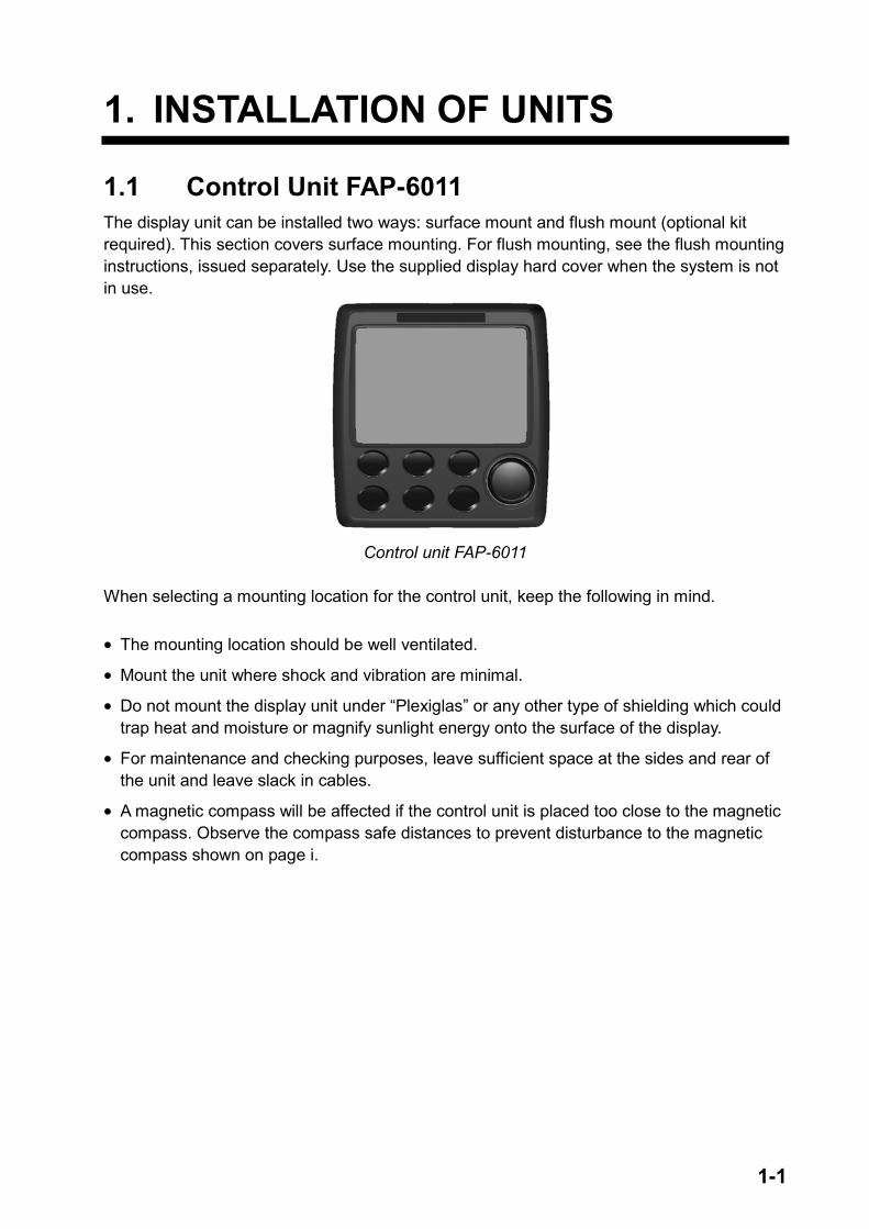
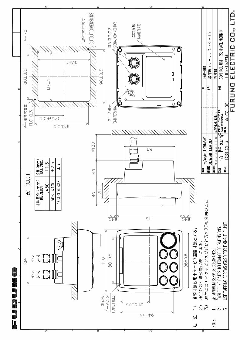
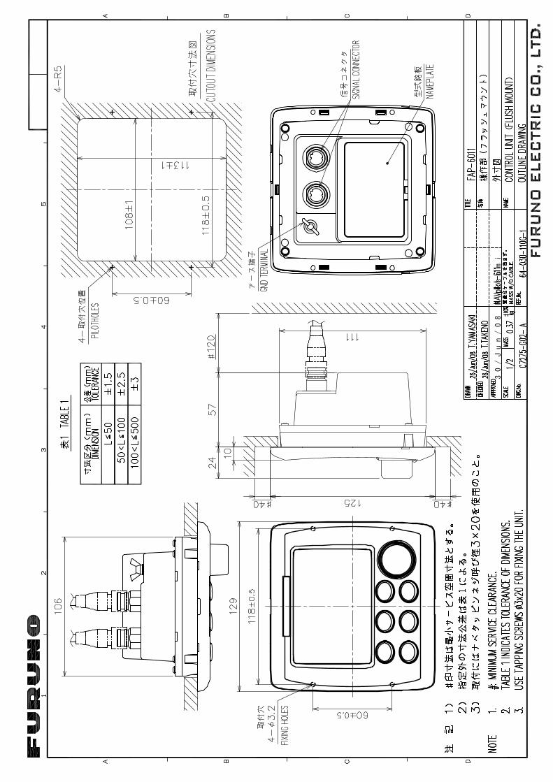
1.1 Control Unit FAP-6011 The display unit can be installed two ways: surface mount and flush mount (optional kit required). This section covers surface mounting. For flush mounting, see the flush mounting instructions, issued separately. Use the supplied display hard cover when the system is not in use.
Control unit FAP-6011
When selecting a mounting location for the control unit, keep the following in mind. • The mounting location should be well ventilated.
• Mount the unit where shock and vibration are minimal.
• Do not mount the display unit under “Plexiglas” or any other type of shielding which could trap heat and moisture or magnify sunlight energy onto the surface of the display.
• For maintenance and checking purposes, leave sufficient space at the sides and rear of the unit and leave slack in cables.
• A magnetic compass will be affected if the control unit is placed too close to the magnetic compass. Observe the compass safe distances to prevent disturbance to the magnetic compass shown on page i.
1. INSTALLATION OF UNITS
1-2
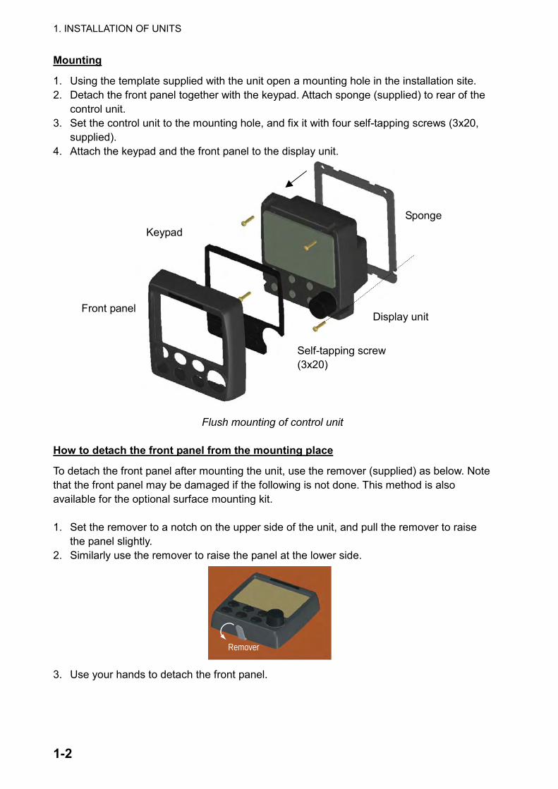
Mounting
1. Using the template supplied with the unit open a mounting hole in the installation site. 2. Detach the front panel together with the keypad. Attach sponge (supplied) to rear of the
control unit. 3. Set the control unit to the mounting hole, and fix it with four self-tapping screws (3x20,
supplied). 4. Attach the keypad and the front panel to the display unit.
Flush mounting of control unit
How to detach the front panel from the mounting place
To detach the front panel after mounting the unit, use the remover (supplied) as below. Note that the front panel may be damaged if the following is not done. This method is also available for the optional surface mounting kit. 1. Set the remover to a notch on the upper side of the unit, and pull the remover to raise
the panel slightly. 2. Similarly use the remover to raise the panel at the lower side.
Remover
3. Use your hands to detach the front panel.
Front panel
Keypad
Display unit
Self-tapping screw (3x20)
Sponge
1. INSTALLATION OF UNITS
1-3
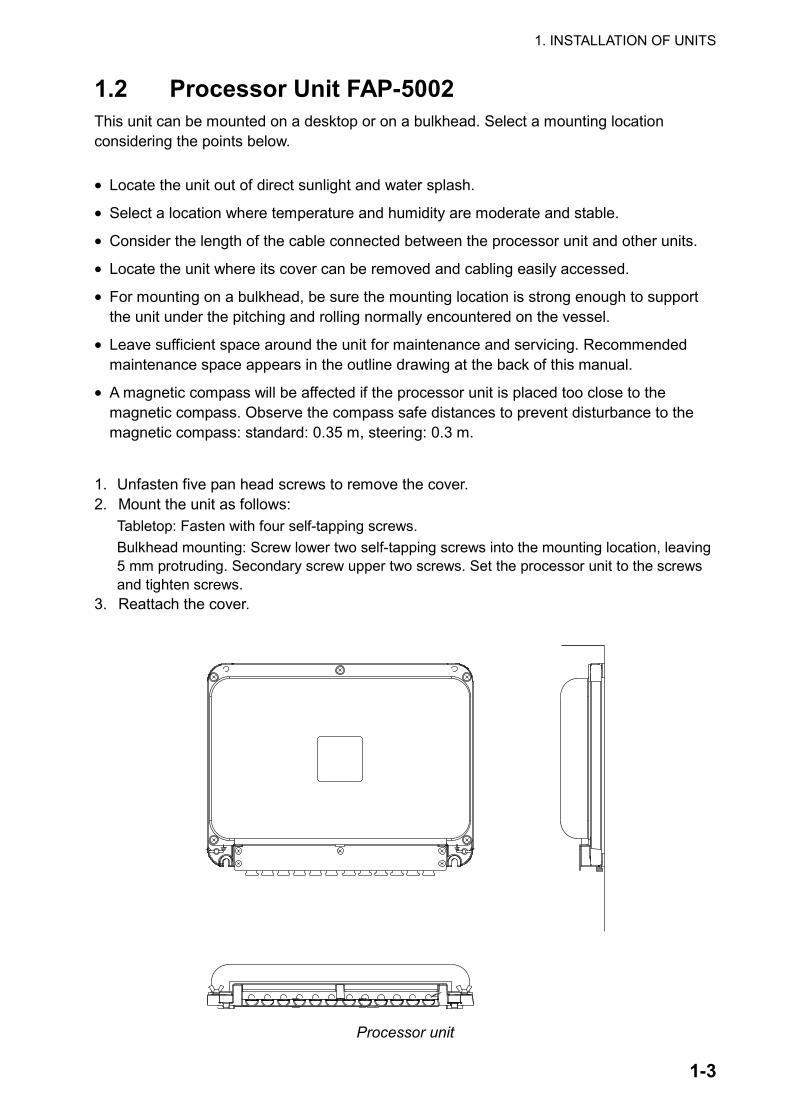
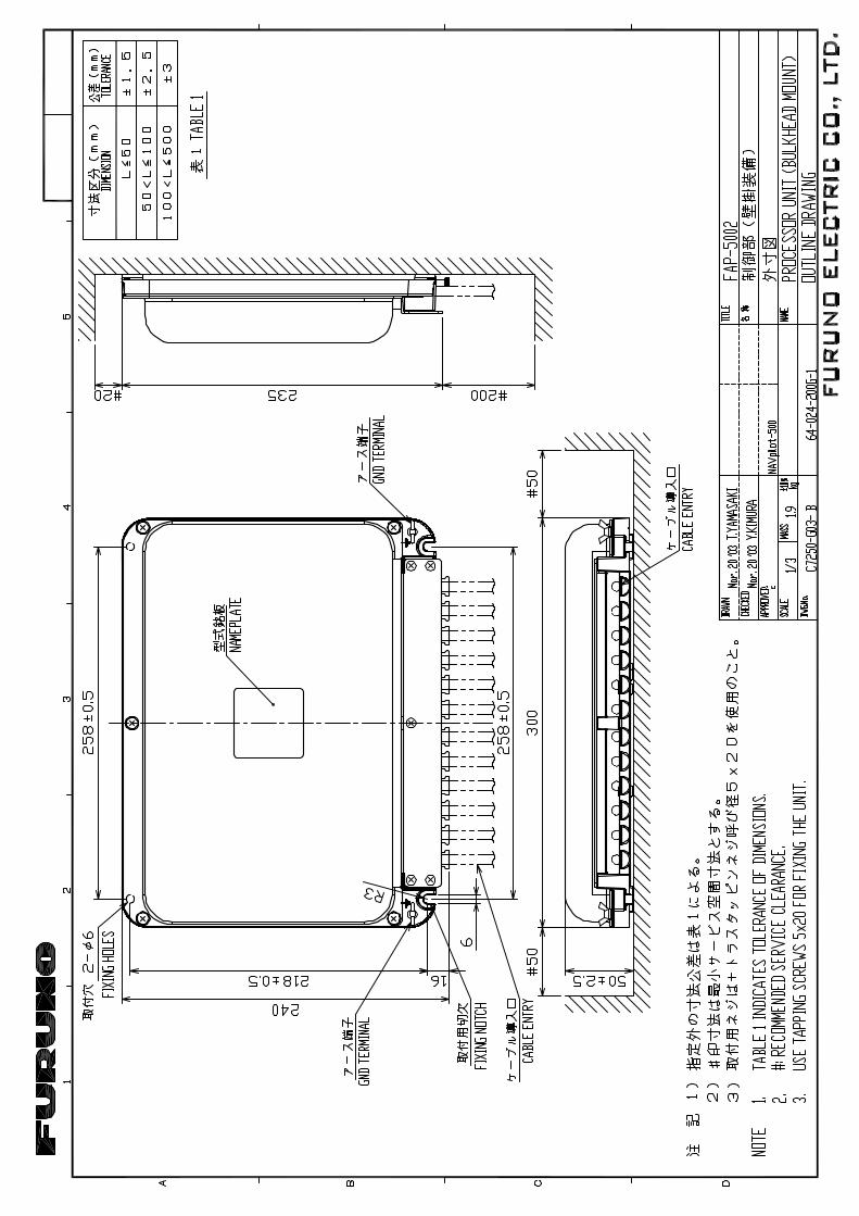
1.2 Processor Unit FAP-5002 This unit can be mounted on a desktop or on a bulkhead. Select a mounting location considering the points below. • Locate the unit out of direct sunlight and water splash.
• Select a location where temperature and humidity are moderate and stable.
• Consider the length of the cable connected between the processor unit and other units.
• Locate the unit where its cover can be removed and cabling easily accessed.
• For mounting on a bulkhead, be sure the mounting location is strong enough to support the unit under the pitching and rolling normally encountered on the vessel.
• Leave sufficient space around the unit for maintenance and servicing. Recommended maintenance space appears in the outline drawing at the back of this manual.
• A magnetic compass will be affected if the processor unit is placed too close to the magnetic compass. Observe the compass safe distances to prevent disturbance to the magnetic compass: standard: 0.35 m, steering: 0.3 m.
1. Unfasten five pan head screws to remove the cover. 2. Mount the unit as follows:
Tabletop: Fasten with four self-tapping screws. Bulkhead mounting: Screw lower two self-tapping screws into the mounting location, leaving 5 mm protruding. Secondary screw upper two screws. Set the processor unit to the screws and tighten screws.
3. Reattach the cover.
Processor unit
1. INSTALLATION OF UNITS
1-4
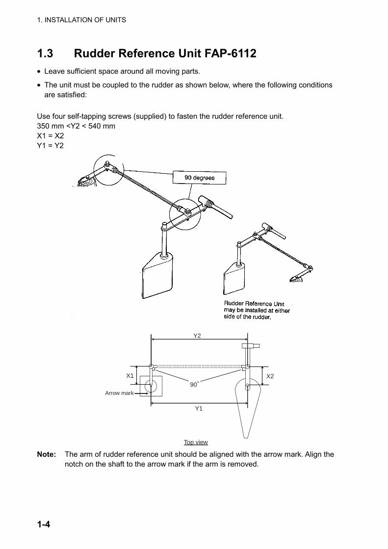
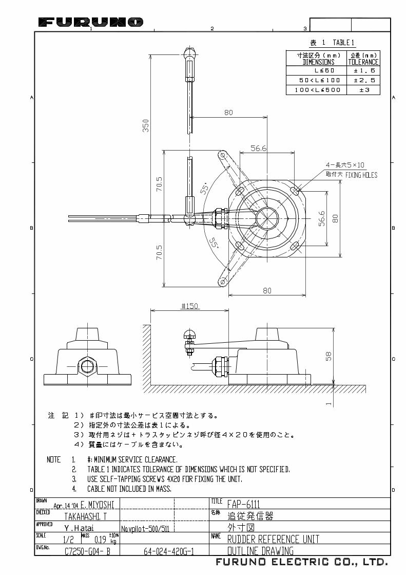
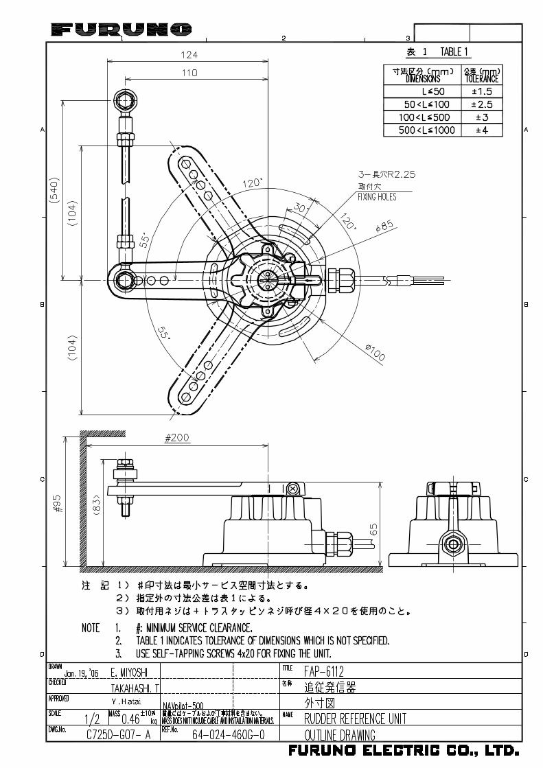
1.3 Rudder Reference Unit FAP-6112 • Leave sufficient space around all moving parts.
• The unit must be coupled to the rudder as shown below, where the following conditions are satisfied:
Use four self-tapping screws (supplied) to fasten the rudder reference unit. 350 mm <Y2 < 540 mm X1 = X2 Y1 = Y2
X1 X2
Y1
Y2
90
Top view
Arrow mark
Note: The arm of rudder reference unit should be aligned with the arrow mark. Align the
notch on the shaft to the arrow mark if the arm is removed.

1. INSTALLATION OF UNITS
1-5
Relationship between Reversing Pump Flow Rate and Steering Cylinder Capacity
The table below shows a rough guideline to determine the proper Reversing Pump Flow Rate to match with the Hydraulic Steering Cylinder capacity. Your experience with specific boat designs may cause you to select a pump/cylinder relationship outside of the range of these guidelines.
Hardover to Hardover is 70º. Hardover to Hardover is 90º.
1.0 cu. in./sec. pump 5.85 to 17.5 cu. in. 7.5 to 22.5 cu. in.
1.6 cu. in./sec. pump 9.36 to 28.0 cu. in. 12.0 to 36.0 cu. in. • If the Hydraulic Cylinder capacity is much smaller than the recommended values in the
table, the rudder turning speed maybe too fast for the pilot to deliver proper performance. The rudder deadband will decrease and the Navpilot System may not apply enough voltage for the pump motor to start because the applied “Duty Cycle” will be too low.
• If the Hydraulic Cylinder capacity is much larger than the recommended values in the table, the rudder turning speed may be too slow to allow the Navpilot System to control the boat effectively.
1.4 Remote Controllers (option) Two remote controllers may be connected to the processor unit FAP-5002. To connect three or four remote controllers, the optional distributor FAP-6800 is required. Note 1: The distributor FAP-6800 enables connection of three NFU (Non-Follow Up) type remote controllers (button and lever) to the processor unit. Note 2: Keep the remote controller out of water splash. Dial type remote controller FAP-5551/5552
Hooking up FAP-5551/5552
1. INSTALLATION OF UNITS
1-6
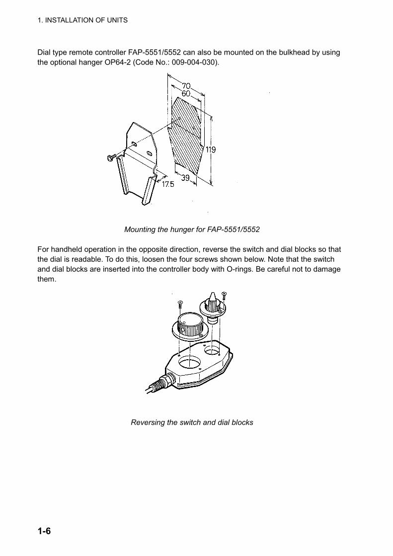
Dial type remote controller FAP-5551/5552 can also be mounted on the bulkhead by using the optional hanger OP64-2 (Code No.: 009-004-030).
Mounting the hunger for FAP-5551/5552
For handheld operation in the opposite direction, reverse the switch and dial blocks so that the dial is readable. To do this, loosen the four screws shown below. Note that the switch and dial blocks are inserted into the controller body with O-rings. Be careful not to damage them.
Reversing the switch and dial blocks
1. INSTALLATION OF UNITS
1-7
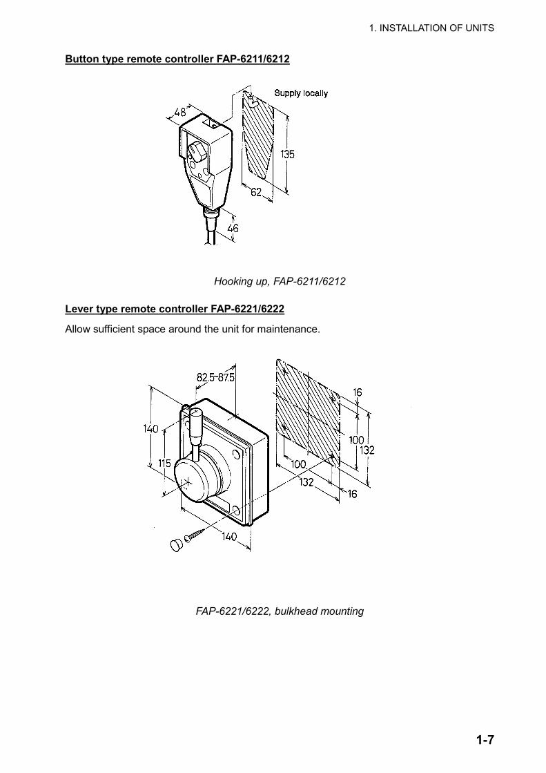
Button type remote controller FAP-6211/6212
Hooking up, FAP-6211/6212
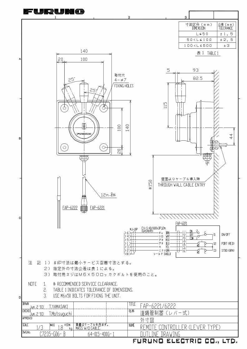
Lever type remote controller FAP-6221/6222
Allow sufficient space around the unit for maintenance.
FAP-6221/6222, bulkhead mounting
1. INSTALLATION OF UNITS
1-8
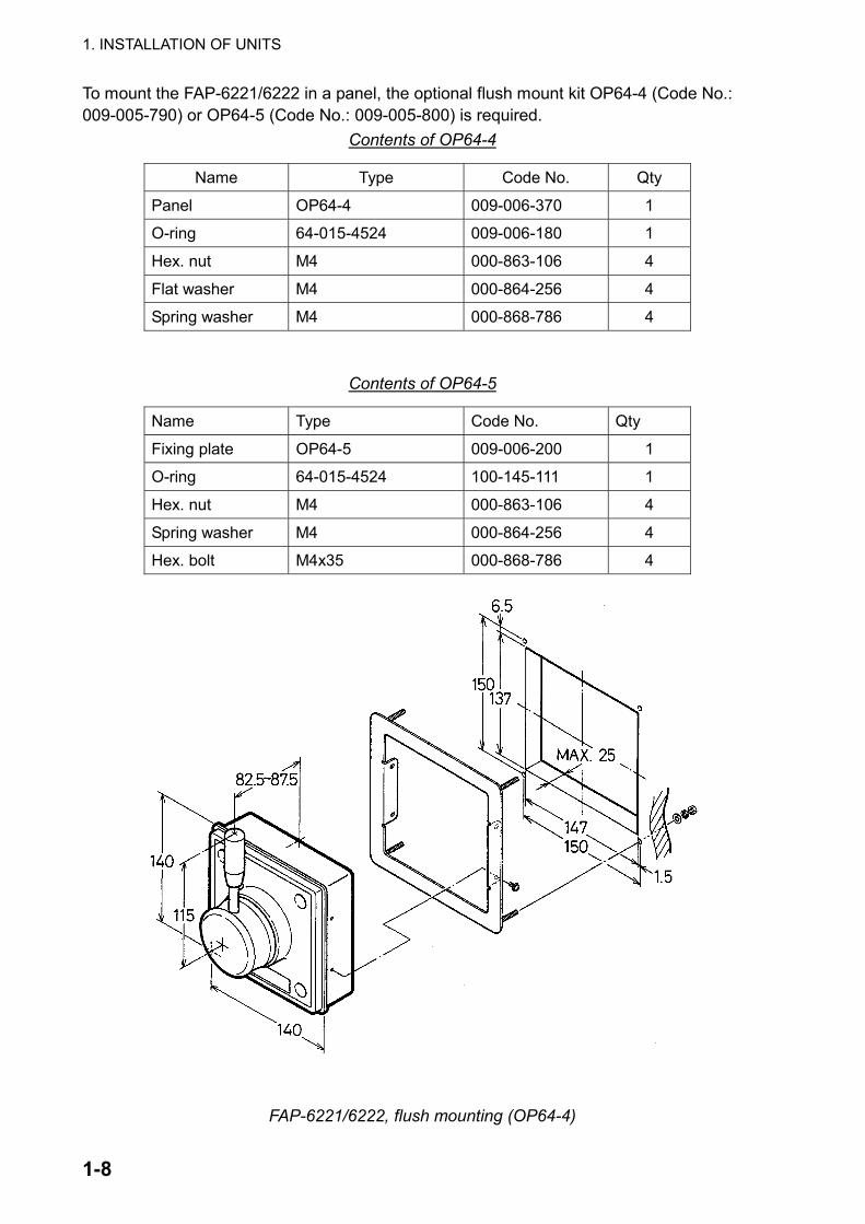
To mount the FAP-6221/6222 in a panel, the optional flush mount kit OP64-4 (Code No.: 009-005-790) or OP64-5 (Code No.: 009-005-800) is required.
Contents of OP64-4
Name Type Code No. Qty
Panel OP64-4 009-006-370 1
O-ring 64-015-4524 009-006-180 1
Hex. nut M4 000-863-106 4
Flat washer M4 000-864-256 4
Spring washer M4 000-868-786 4
Contents of OP64-5
Name Type Code No. Qty
Fixing plate OP64-5 009-006-200 1
O-ring 64-015-4524 100-145-111 1
Hex. nut M4 000-863-106 4
Spring washer M4 000-864-256 4
Hex. bolt M4x35 000-868-786 4
FAP-6221/6222, flush mounting (OP64-4)
1. INSTALLATION OF UNITS
1-9
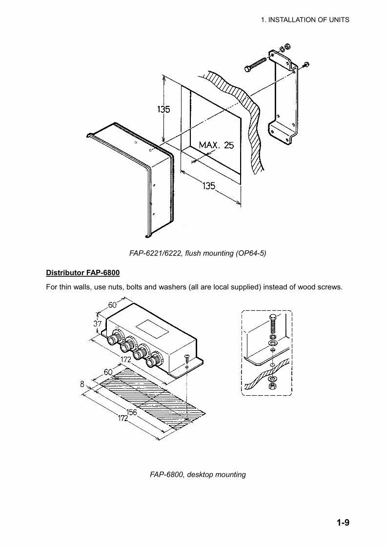
FAP-6221/6222, flush mounting (OP64-5)
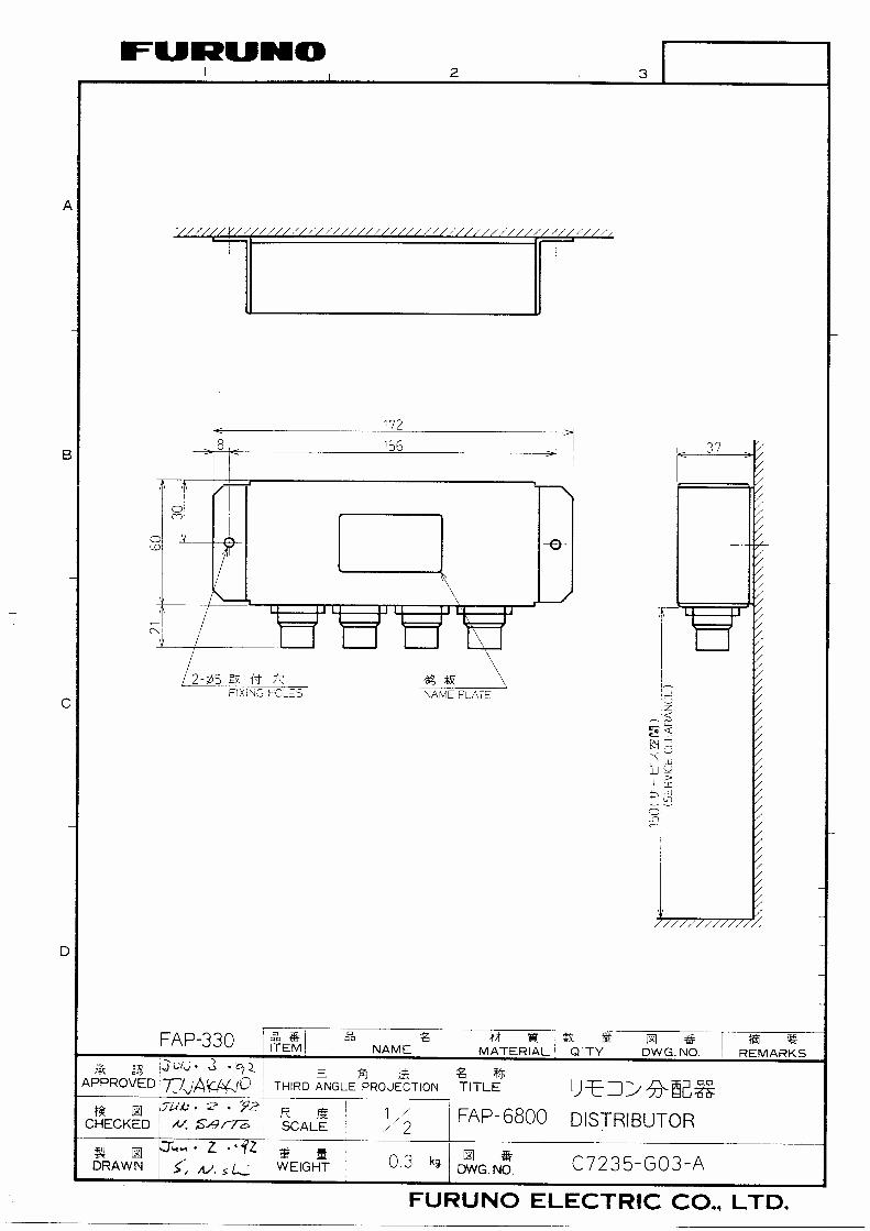
Distributor FAP-6800
For thin walls, use nuts, bolts and washers (all are local supplied) instead of wood screws.
FAP-6800, desktop mounting

1. INSTALLATION OF UNITS
1-10
This page is intentionally left blank.

2-1
2. WIRING
2.1 Wiring System All units are connected to the processor unit. The cables should be separated as far as possible from cables carrying radio frequency or pulsed signals. At least one meter separation is recommended.
Reversible pump
Solenoid valve
Hydrauliclinear drive
Power supply12-24 VDC
Terminator MJ-A7SPF0011*(supplied)
MJ-A7SPF0010-100C (supplied)/150C (option)/200C (option)
MJ-A7SPF0012-100C
Control unitFAP-6011
Processor unit FAP-5002
Terminator MJ-A7SPF0011*(supplied)
MJ-A7SPF0010-100
PG-500
Rudderreferenceindicator
FAP-6112
Remotecontroller
orDistributor
Remotecontroller
orDistributor
PC
NMEA OUT(FI-30 etc.)
NMEA IN(FI-30 etc.) NMEA IN/OUT
(FI-30 etc.)
*Attach the terminator to the empty connector of the last control unit in the series. Wiring
2. WIRING
2-2
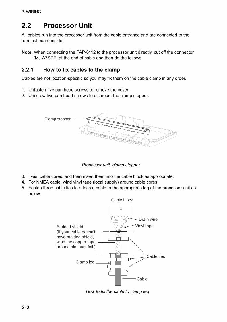
2.2 Processor Unit All cables run into the processor unit from the cable entrance and are connected to the terminal board inside. Note: When connecting the FAP-6112 to the processor unit directly, cut off the connector
(MJ-A7SPF) at the end of cable and then do the follows. 2.2.1 How to fix cables to the clamp Cables are not location-specific so you may fix them on the cable clamp in any order. 1. Unfasten five pan head screws to remove the cover. 2. Unscrew five pan head screws to dismount the clamp stopper.
Clamp stopper
Processor unit, clamp stopper
3. Twist cable cores, and then insert them into the cable block as appropriate. 4. For NMEA cable, wind vinyl tape (local supply) around cable cores. 5. Fasten three cable ties to attach a cable to the appropriate leg of the processor unit as
below.
Clamp leg
Cable
Cable ties
Braided shield(If your cable doesn't have braided shield, wind the copper tape around alminum foil.)
Drain wire
Vinyl tape
Cable block
How to fix the cable to clamp leg
2. WIRING
2-3
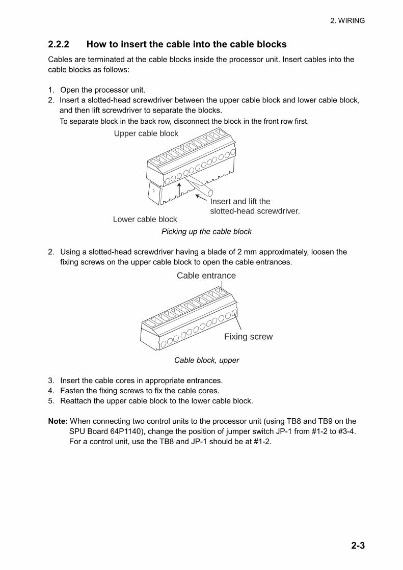
2.2.2 How to insert the cable into the cable blocks Cables are terminated at the cable blocks inside the processor unit. Insert cables into the cable blocks as follows: 1. Open the processor unit. 2. Insert a slotted-head screwdriver between the upper cable block and lower cable block,
and then lift screwdriver to separate the blocks. To separate block in the back row, disconnect the block in the front row first.
Insert and lift the slotted-head screwdriver.
Lower cable block
Upper cable block
Picking up the cable block
2. Using a slotted-head screwdriver having a blade of 2 mm approximately, loosen the
fixing screws on the upper cable block to open the cable entrances.
Fixing screw
Cable entrance
Cable block, upper
3. Insert the cable cores in appropriate entrances. 4. Fasten the fixing screws to fix the cable cores. 5. Reattach the upper cable block to the lower cable block. Note: When connecting two control units to the processor unit (using TB8 and TB9 on the
SPU Board 64P1140), change the position of jumper switch JP-1 from #1-2 to #3-4. For a control unit, use the TB8 and JP-1 should be at #1-2.

2. WIRING
2-4
Control unit
Remote controller
Rudder reference unit
HeadingSensor
(PG-500)
NMEAIn/Out
NMEAOut
NMEAIn
RS232C
Ext. Buzzer
Ship'smains Motor
PWR+,B/Clutch
JP-1#1-2#3-4
TB9 TB10
1 2 3 4 5
#1-2#3-4 JP-2
Processor unit, inside view
2.2.3 Power and Motor cable For ship’s mains cable and motor line cable, use the recommended shielded cable in the table shown below. Connect the ship’s mains cable to a breaker which has a rating suitable to the motor.
Motor Voltage 12 VDC 24 VDC Cable length Section of core
(mm²) AWG Section of core (mm²) AWG
3 m or less 2.5 12 2.5 12 6 m or less 4 10 2.5 12 10 m or less 6 8 4 10 16 m or less 10 6 6 8
2. WIRING
2-5
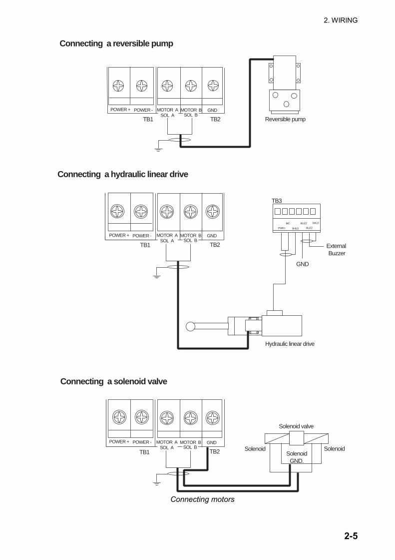
MOTOR A MOTOR B GNDPOWER + POWER -SOL A SOL B
TB2TB1 Reversible pump
MOTOR A MOTOR B GNDPOWER + POWER -SOL A SOL B
TB2TB1
TB3
PWR+
SHLDB/C
SHLD
BUZZ
Hydraulic linear drive
MOTOR A MOTOR B GNDPOWER + POWER -SOL A SOL B
TB2TB1 SolenoidSolenoid
GND.
Solenoid
Solenoid valve
Connecting a reversible pump
Connecting a hydraulic linear drive
Connecting a solenoid valve
BUZZ
External Buzzer
GND
Connecting motors
2. WIRING
2-6
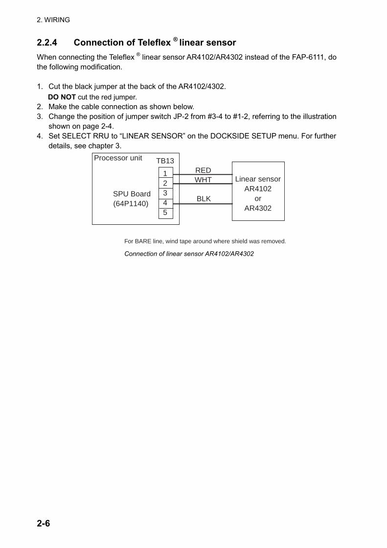
2.2.4 Connection of Teleflex ® linear sensor When connecting the Teleflex ® linear sensor AR4102/AR4302 instead of the FAP-6111, do the following modification. 1. Cut the black jumper at the back of the AR4102/4302.
DO NOT cut the red jumper. 2. Make the cable connection as shown below. 3. Change the position of jumper switch JP-2 from #3-4 to #1-2, referring to the illustration
shown on page 2-4. 4. Set SELECT RRU to “LINEAR SENSOR” on the DOCKSIDE SETUP menu. For further
details, see chapter 3.
12345
SPU Board(64P1140)
TB13
Linear sensorAR4102
or AR4302
REDWHT
BLK
Processor unit
For BARE line, wind tape around where shield was removed.
Connection of linear sensor AR4102/AR4302
2. WIRING
2-7
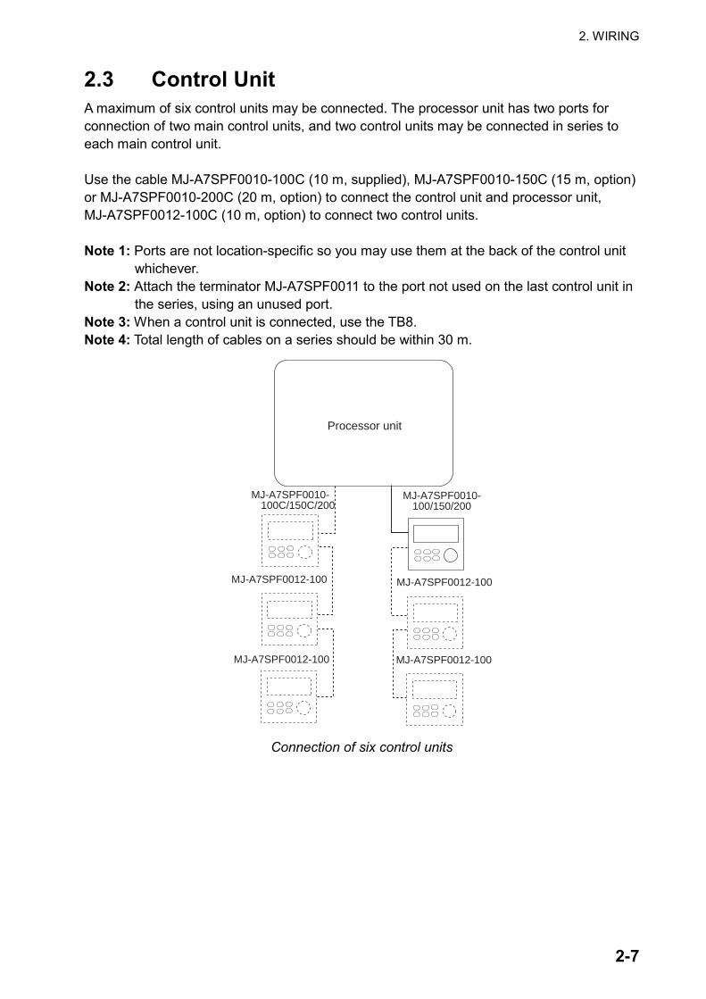
2.3 Control Unit A maximum of six control units may be connected. The processor unit has two ports for connection of two main control units, and two control units may be connected in series to each main control unit. Use the cable MJ-A7SPF0010-100C (10 m, supplied), MJ-A7SPF0010-150C (15 m, option) or MJ-A7SPF0010-200C (20 m, option) to connect the control unit and processor unit, MJ-A7SPF0012-100C (10 m, option) to connect two control units. Note 1: Ports are not location-specific so you may use them at the back of the control unit
whichever. Note 2: Attach the terminator MJ-A7SPF0011 to the port not used on the last control unit in
the series, using an unused port. Note 3: When a control unit is connected, use the TB8. Note 4: Total length of cables on a series should be within 30 m.
Processor unit
MJ-A7SPF0010-100C/150C/200
MJ-A7SPF0010-100/150/200
MJ-A7SPF0012-100MJ-A7SPF0012-100
MJ-A7SPF0012-100MJ-A7SPF0012-100
Connection of six control units
2. WIRING
2-8
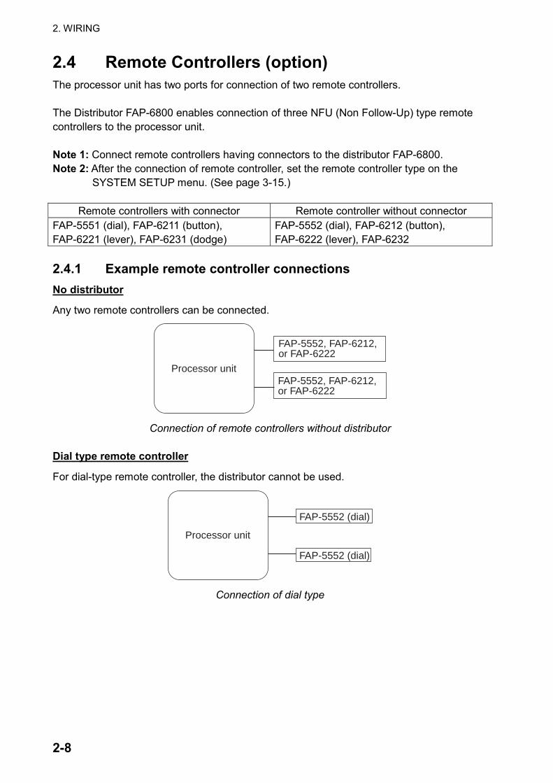
2.4 Remote Controllers (option) The processor unit has two ports for connection of two remote controllers. The Distributor FAP-6800 enables connection of three NFU (Non Follow-Up) type remote controllers to the processor unit. Note 1: Connect remote controllers having connectors to the distributor FAP-6800. Note 2: After the connection of remote controller, set the remote controller type on the
SYSTEM SETUP menu. (See page 3-15.)
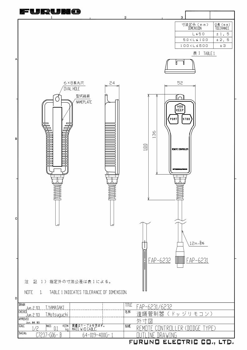
Remote controllers with connector Remote controller without connector FAP-5551 (dial), FAP-6211 (button), FAP-6221 (lever), FAP-6231 (dodge)
FAP-5552 (dial), FAP-6212 (button), FAP-6222 (lever), FAP-6232
2.4.1 Example remote controller connections No distributor
Any two remote controllers can be connected.
FAP-5552, FAP-6212, or FAP-6222
Processor unitFAP-5552, FAP-6212, or FAP-6222
Connection of remote controllers without distributor
Dial type remote controller
For dial-type remote controller, the distributor cannot be used.
FAP-5552 (dial)
Processor unit
FAP-5552 (dial)
Connection of dial type

2. WIRING
2-9
Button or lever remote controller with distributor
Maximum six button or lever remote controllers can be connected.
FAP-6211 (button)/6221 (lever)
Processor unit
FAP-6211 (button)/6221 (lever)
FAP-6211 (button)/6221 (lever)
FAP-6211 (button)/6221 (lever)
FAP-6211 (button)/6221 (lever)
FAP-6211 (button)/6221 (lever) Connection of button or lever remote controllers
Dodge remote controller with distributor
Maximum six dodge type remote controllers can be connected.
FAP-6231 (dodge type)
Processor unit
FAP-6231 (dodge type)
FAP-6231 (dodge type)
FAP-6231 (dodge type)
FAP-6231 (dodge type)
FAP-6231 (dodge type) Connection of six dodge remote controllers

2. WIRING
2-10
2.4.2 Prohibited remote controller connections The following remote controller connections are not possible. Wrong connection 1
Different types of remote controllers cannot be connected.
FAP-6211 (button)
Processor unit
FAP-6221 (lever)FAP-6231 (dodge)
FAP-6211 (button)FAP-6221 (lever)FAP-6231 (dodge)
Wrong connection 1
Wrong connection 2
Only one dial remote controller can be connected.
FAP-5551 (dial)
Processor unit
FAP-5551 (dial)
FAP-5551 (dial)FAP-5551 (dial)
Wrong connection 2

2. WIRING
2-11
Wrong connection 3
Multiple distributors cannot be connected.
Processor unit
Wrong connection 3
2.5 Connection of Instruments FI-30 The FI-30 series has various sensors, such as speed, depth, wind, etc. These sensors can be connected to the NAVpilot-500/511 via the FI-30 server, and the NAVpilot-500/511 can show data from them on its graphic display. To connect the NAVpilot-500 to the FI-30 server, see the connection diagram shown below.
OUT A 1OUT B 2
IN A 3IN B 4
F.G.
1 +12V2 0 V3 OUTPUT A4 OUTPUT B
10 INPUT A11 INPUT B
+ -
NMEA
NMEA GPS
Processor unitFAP-5002
FI-30 Server
NMEA IN/OUT
IN A 3IN B 4
OUT A 3OUT B 4
1 +12V2 0 V3 OUTPUT A4 OUTPUT B
10 INPUT A11 INPUT B
+ -
NMEA
NMEA GPS
Processor unitFAP-5002 FI-30 Server
NMEA OUT
NMEA IN
Connection using the NMEA IN and NMEA OUT ports on FAP-5002
Connection using the NMEA IN/OUT ports on FAP-5002
TB7
TB5
TB6
2. WIRING
2-12
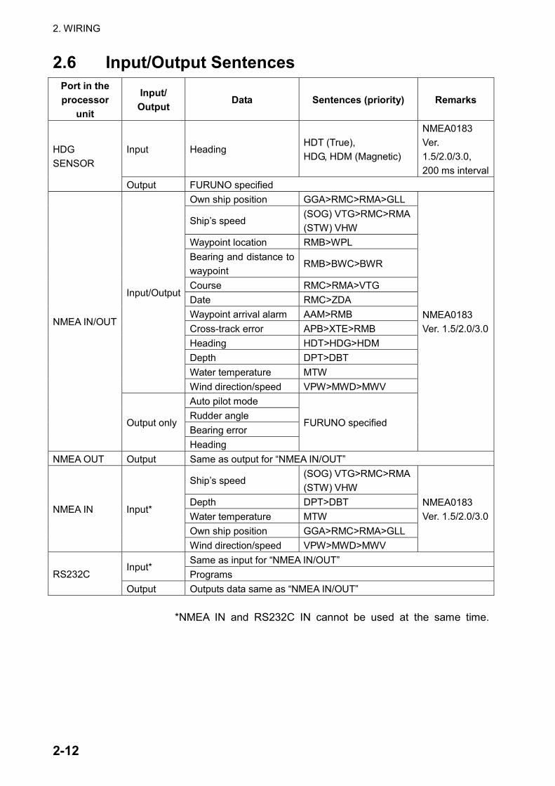
2.6 Input/Output Sentences Port in the processor
unit
Input/ Output
Data Sentences (priority) Remarks
Input Heading HDT (True), HDG, HDM (Magnetic)
NMEA0183 Ver. 1.5/2.0/3.0, 200 ms interval
HDG SENSOR
Output FURUNO specified Own ship position GGA>RMC>RMA>GLL
Ship’s speed (SOG) VTG>RMC>RMA (STW) VHW
Waypoint location RMB>WPL Bearing and distance to waypoint
RMB>BWC>BWR
Course RMC>RMA>VTG Date RMC>ZDA Waypoint arrival alarm AAM>RMB Cross-track error APB>XTE>RMB Heading HDT>HDG>HDM Depth DPT>DBT Water temperature MTW
Input/Output
Wind direction/speed VPW>MWD>MWV Auto pilot mode Rudder angle Bearing error
NMEA IN/OUT
Output only
Heading
FURUNO specified
NMEA0183 Ver. 1.5/2.0/3.0
NMEA OUT Output Same as output for “NMEA IN/OUT”
Ship’s speed (SOG) VTG>RMC>RMA (STW) VHW
Depth DPT>DBT Water temperature MTW Own ship position GGA>RMC>RMA>GLL
NMEA IN Input*
Wind direction/speed VPW>MWD>MWV
NMEA0183 Ver. 1.5/2.0/3.0
Same as input for “NMEA IN/OUT” Input*
Programs RS232C Output Outputs data same as “NMEA IN/OUT”
*NMEA IN and RS232C IN cannot be used at the same time.
3-1
3. ADJUSTMENTS
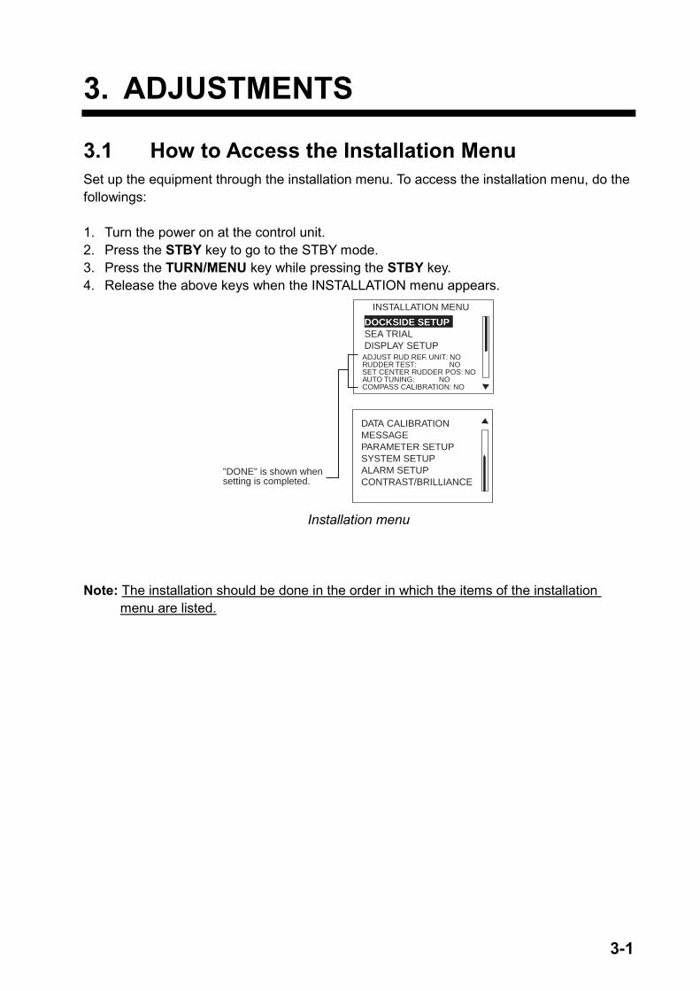
3.1 How to Access the Installation Menu Set up the equipment through the installation menu. To access the installation menu, do the followings: 1. Turn the power on at the control unit. 2. Press the STBY key to go to the STBY mode. 3. Press the TURN/MENU key while pressing the STBY key. 4. Release the above keys when the INSTALLATION menu appears.
"DONE" is shown when setting is completed.
DOCKSIDE SETUPSEA TRIALDISPLAY SETUP
DATA CALIBRATIONMESSAGEPARAMETER SETUPSYSTEM SETUPALARM SETUPCONTRAST/BRILLIANCE
ADJUST RUD REF. UNIT: NORUDDER TEST: NOSET CENTER RUDDER POS: NOAUTO TUNING: NOCOMPASS CALIBRATION: NO
INSTALLATION MENU
Installation menu
Note: The installation should be done in the order in which the items of the installation menu are listed.
3. ADJUSTMENTS
3-2
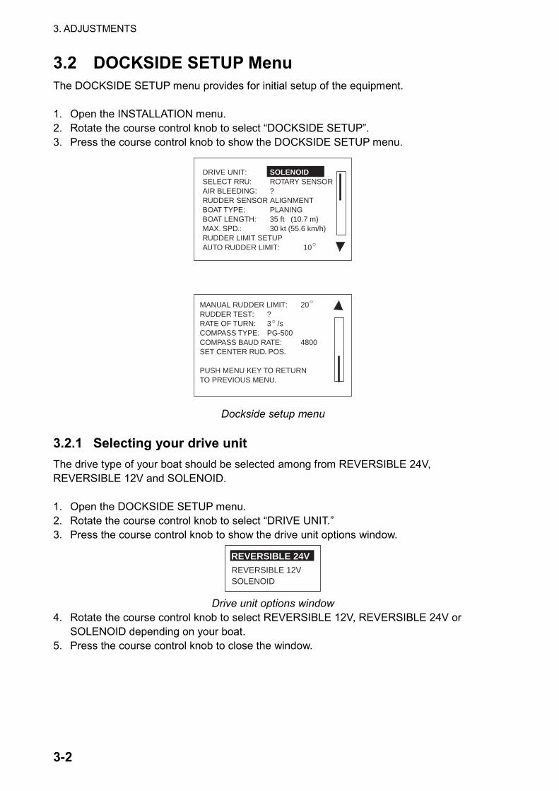
3.2 DOCKSIDE SETUP Menu The DOCKSIDE SETUP menu provides for initial setup of the equipment. 1. Open the INSTALLATION menu. 2. Rotate the course control knob to select “DOCKSIDE SETUP”. 3. Press the course control knob to show the DOCKSIDE SETUP menu.
DRIVE UNIT: SOLENOIDSELECT RRU: ROTARY SENSORAIR BLEEDING: ?RUDDER SENSOR ALIGNMENTBOAT TYPE: PLANINGBOAT LENGTH: 35 ft (10.7 m)MAX. SPD.: 30 kt (55.6 km/h)RUDDER LIMIT SETUPAUTO RUDDER LIMIT: 10
MANUAL RUDDER LIMIT: 20RUDDER TEST: ?RATE OF TURN: 3 /sCOMPASS TYPE: PG-500COMPASS BAUD RATE: 4800SET CENTER RUD. POS.
PUSH MENU KEY TO RETURNTO PREVIOUS MENU.
Dockside setup menu
3.2.1 Selecting your drive unit The drive type of your boat should be selected among from REVERSIBLE 24V, REVERSIBLE 12V and SOLENOID. 1. Open the DOCKSIDE SETUP menu. 2. Rotate the course control knob to select “DRIVE UNIT.” 3. Press the course control knob to show the drive unit options window.
REVERSIBLE 12VSOLENOID
REVERSIBLE 24V
Drive unit options window
4. Rotate the course control knob to select REVERSIBLE 12V, REVERSIBLE 24V or SOLENOID depending on your boat.
5. Press the course control knob to close the window.

3. ADJUSTMENTS
3-3
3.2.2 Selecting the type of rudder reference unit Select the type of your rudder reference unit at here. 1. Rotate the course control knob to select “SELECT RRU”, and then press the course
control knob. The select RRU options window appears.
LINEAR SENSORROTARY SENSOR
Select RRU options window
2. Rotate the course control knob to select ROTARY SENSOR or LINEAR SENSOR. ROTARY SENSOR: The rudder reference unit FAP-6111 is connected. LINEAR SENSOR: The Teleflex® linear sensor AR4102 or AR4302 is connected.
3. Press the course control knob to close the window.
Note: When selecting LINEAR SENSOR, change the JP2 position certainly referring to page 2-4.
3.2.3 Bleeding air in the oil cylinder Always confirm that all of the air is bled from the steering system by moving the rudder automatically or manually.
WARNINGConfirm that no one is near the rudderwhen bleeding air from oil cylinder.
The rudder may move unexpectedly,possibly causing bodily injury.
1. Rotate the course control knob to select “AIR BLEEDING”, and then press the course
control knob to show the air bleeding options window. There are modes to bleed air from the system. The arrow key mode allows you to control the pump motor to bleed the system directly from the Navpilot control unit. The RRU mode allows you to turn the rudder reference arm in the lazaretto or steering gear room to control the pump motor remotely.
USE KEYSUSE RRU
NO
Air bleeding options window 2. Rotate the course control knob to select USE ◄► KEYS or USE RRU as appropriate. 3. Press the course control knob to show the rudder indicator.
3. ADJUSTMENTS
3-4
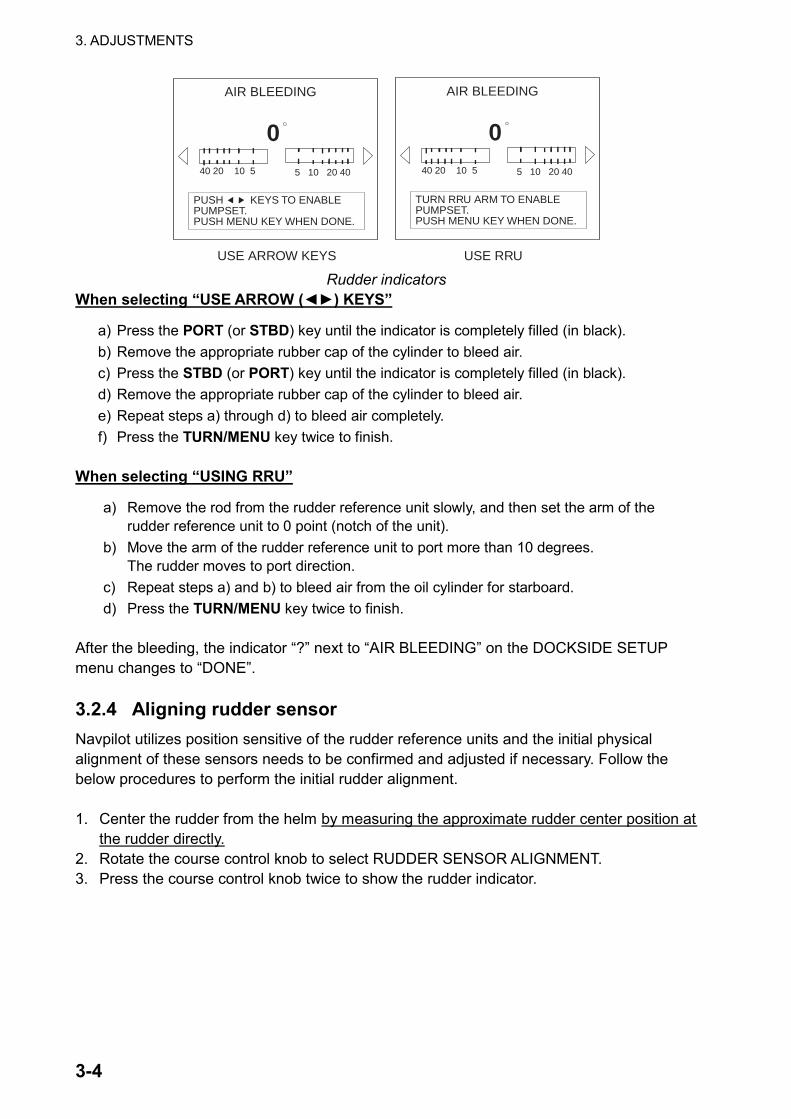
AIR BLEEDING
40 20 10 5 5 10 20 40
0
PUSH KEYS TO ENABLEPUMPSET.PUSH MENU KEY WHEN DONE.
AIR BLEEDING
40 20 10 5 5 10 20 40
0
TURN RRU ARM TO ENABLEPUMPSET.PUSH MENU KEY WHEN DONE.
USE ARROW KEYS USE RRU Rudder indicators
When selecting “USE ARROW (◄►) KEYS”
a) Press the PORT (or STBD) key until the indicator is completely filled (in black). b) Remove the appropriate rubber cap of the cylinder to bleed air. c) Press the STBD (or PORT) key until the indicator is completely filled (in black). d) Remove the appropriate rubber cap of the cylinder to bleed air. e) Repeat steps a) through d) to bleed air completely. f) Press the TURN/MENU key twice to finish.
When selecting “USING RRU”
a) Remove the rod from the rudder reference unit slowly, and then set the arm of the rudder reference unit to 0 point (notch of the unit).
b) Move the arm of the rudder reference unit to port more than 10 degrees. The rudder moves to port direction.
c) Repeat steps a) and b) to bleed air from the oil cylinder for starboard. d) Press the TURN/MENU key twice to finish.
After the bleeding, the indicator “?” next to “AIR BLEEDING” on the DOCKSIDE SETUP menu changes to “DONE”. 3.2.4 Aligning rudder sensor Navpilot utilizes position sensitive of the rudder reference units and the initial physical alignment of these sensors needs to be confirmed and adjusted if necessary. Follow the below procedures to perform the initial rudder alignment. 1. Center the rudder from the helm by measuring the approximate rudder center position at
the rudder directly. 2. Rotate the course control knob to select RUDDER SENSOR ALIGNMENT. 3. Press the course control knob twice to show the rudder indicator.

3. ADJUSTMENTS
3-5
40 20 10 5 5 10 20 40
0
RRU ALIGNMENT
RRU ALIGNMENT
Press the course control knob.
MEASURE RUDDER CENTERPOSITION AND CONFIRMDISPLAYED VALUE IS <5.IF NOT, ADJUST RRU ARM ORMAGNET. NAVPILOT WILL CORRECT REVERSED P & SINDICATION LATER.
ALIGNMENT TONE: ON
Rudder sensor alignment menu 4. With the rudder still physically centered, confirm that the displayed rudder angle
indication is less than or equal to ±5º. If not you must adjust the rudder sensor body or arm position so that the indicator is within ±5º before continuing. If you are installing a linear sensor, move the magnet sensor so that the indicator is within ±5º before continuing. Alignment Tone: Note that there is an alignment tone that you may use to help you make this adjustment remotely, when the indicator is within ±5º, the beep sounds continuously. If you do not need or want to hear the alignment tone, you may turn it off by pressing the course control knob and selecting “OFF” in the ALIGNMENT TONE window.
5. After you have confirmed this step and made any necessary adjustments, push the course control knob to close the window and return to the DOCKSIDE SETUP menu.
3.2.5 Selecting boat type Select your boat type: PLANING, SEMI_PLANING DISPLACEMENT or SAILBOAT depending on your boat specification. The type of boat selected affects the steering parameters and the functions available in the autopilot system. 1. Rotate the course control knob to select “BOAT TYPE”. 2. Press the course control knob to show the boat type options window.
SEMI_PLANINGDISPLACEMENTSAILBOAT
PLANING
Boat type options window
3. Rotate the course control knob to select PLANING, SEMI_PLANING, DISPLACEMENT
or SAILBOAT as appropriate. 4. Press the course control knob to close the window.
3. ADJUSTMENTS
3-6
3.2.6 Entering boat length Enter the actual boat length, between 1 and 80 feet (0.3 and 24.4 m). This length may affect the steering parameters. 1. Rotate the course control knob to select “BOAT LENGTH”. 2. Press the course control knob and the current value is circumscribed with a double
rectangle. 3. Rotate the course control knob to set the boat length. 4. Press the course control knob to finish. 3.2.7 Entering maximum speed Enter the maximum speed of your boat, between 1 and 99 kt (1.9 and 183.3 km/h). The speed entered affects the steering parameters. 1. Rotate the course control knob to select “MAX. SPD.” from the DOCKSIDE SETUP
menu. 2. Press the course control knob and the current value is circumscribed with a double
rectangle. 3. Rotate the course control knob to set maximum speed. 4. Press the course control knob to finish. 3.2.8 Setting port and starboard rudder limit In this mode, you must set the maximum rudder limits or “hard-over” points for the rudder system. Once these limits are set, you also need to set the approximate center rudder position before continuing. Note 1: Navpilot will AUTOMATICALLY set the port/starboard direction of the rudder angle
in this step. It does not matter which way the rudder reference unit arm or linear sensor rod is installed as this correction will be done electronically.
Note 2: Navpilot will automatically “linearize” the rudder indication values if the rudder turns
further in one direction than the other direction. Therefore, it is recommended that you make both port and starboard rudder values the same. This will avoid confusion for the customer during operation. Also, numeric value selected is not critical and need not be measured as long as you feel that your estimation is close to the proper value.
Adjust the rudder angle indication as follows. 1. Rotate the course control knob to select “RUDDER LIMIT SETUP.” 2. Press the course control knob twice to show the RUDDER LIMIT SETUP menu.
3. ADJUSTMENTS
3-7
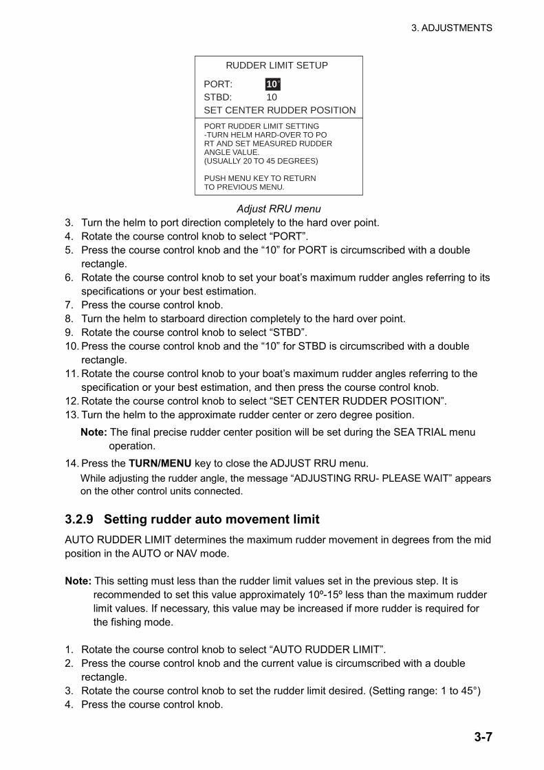
RUDDER LIMIT SETUP
PORT: 10STBD: 10SET CENTER RUDDER POSITION
PORT RUDDER LIMIT SETTING-TURN HELM HARD-OVER TO PORT AND SET MEASURED RUDDERANGLE VALUE.(USUALLY 20 TO 45 DEGREES)
PUSH MENU KEY TO RETURNTO PREVIOUS MENU.
Adjust RRU menu 3. Turn the helm to port direction completely to the hard over point. 4. Rotate the course control knob to select “PORT”. 5. Press the course control knob and the “10” for PORT is circumscribed with a double
rectangle. 6. Rotate the course control knob to set your boat’s maximum rudder angles referring to its
specifications or your best estimation. 7. Press the course control knob. 8. Turn the helm to starboard direction completely to the hard over point. 9. Rotate the course control knob to select “STBD”. 10. Press the course control knob and the “10” for STBD is circumscribed with a double
rectangle. 11. Rotate the course control knob to your boat’s maximum rudder angles referring to the
specification or your best estimation, and then press the course control knob. 12. Rotate the course control knob to select “SET CENTER RUDDER POSITION”. 13. Turn the helm to the approximate rudder center or zero degree position.
Note: The final precise rudder center position will be set during the SEA TRIAL menu operation.
14. Press the TURN/MENU key to close the ADJUST RRU menu. While adjusting the rudder angle, the message “ADJUSTING RRU- PLEASE WAIT” appears on the other control units connected.
3.2.9 Setting rudder auto movement limit AUTO RUDDER LIMIT determines the maximum rudder movement in degrees from the mid position in the AUTO or NAV mode. Note: This setting must less than the rudder limit values set in the previous step. It is
recommended to set this value approximately 10º-15º less than the maximum rudder limit values. If necessary, this value may be increased if more rudder is required for the fishing mode.
1. Rotate the course control knob to select “AUTO RUDDER LIMIT”. 2. Press the course control knob and the current value is circumscribed with a double
rectangle. 3. Rotate the course control knob to set the rudder limit desired. (Setting range: 1 to 45°) 4. Press the course control knob.
3. ADJUSTMENTS
3-8
3.2.10 Setting manual rudder movement limit In the REM (remote) or DODGE mode, usually a wide range of rudder angles are used, and therefore a larger number should be entered. However, the setting must not exceed the rudder limit angle which is inherent to your boat. Rotate the course control knob to select “MANUAL RUDDER LIMIT”. Note: This setting must less than the rudder limit values set in the previous step. It is
recommended to set this value approximately 5º less than the maximum rudder limit values.
1. Press the course control knob and the current value is circumscribed with a double
rectangle. 2. Rotate the course control knob to set the rudder limit desired. (Setting range: 1 to 45°) 3. Press the course control knob. 3.2.11 Checking rudder status The Rudder test checks the following, and then shows the result of the check. • Drive type
• The presence or absence of bypass/clutch circuit
• Rudder dead band
• Rudder speed
• PWM Duty Note: For power steering vessels with an engine driven power steering pump, the engines
must be running and slightly above idle before this test is performed. 1. Rotate the course control knob to select “RUDDER TEST”. 2. Press the course control knob to show the rudder test options window.
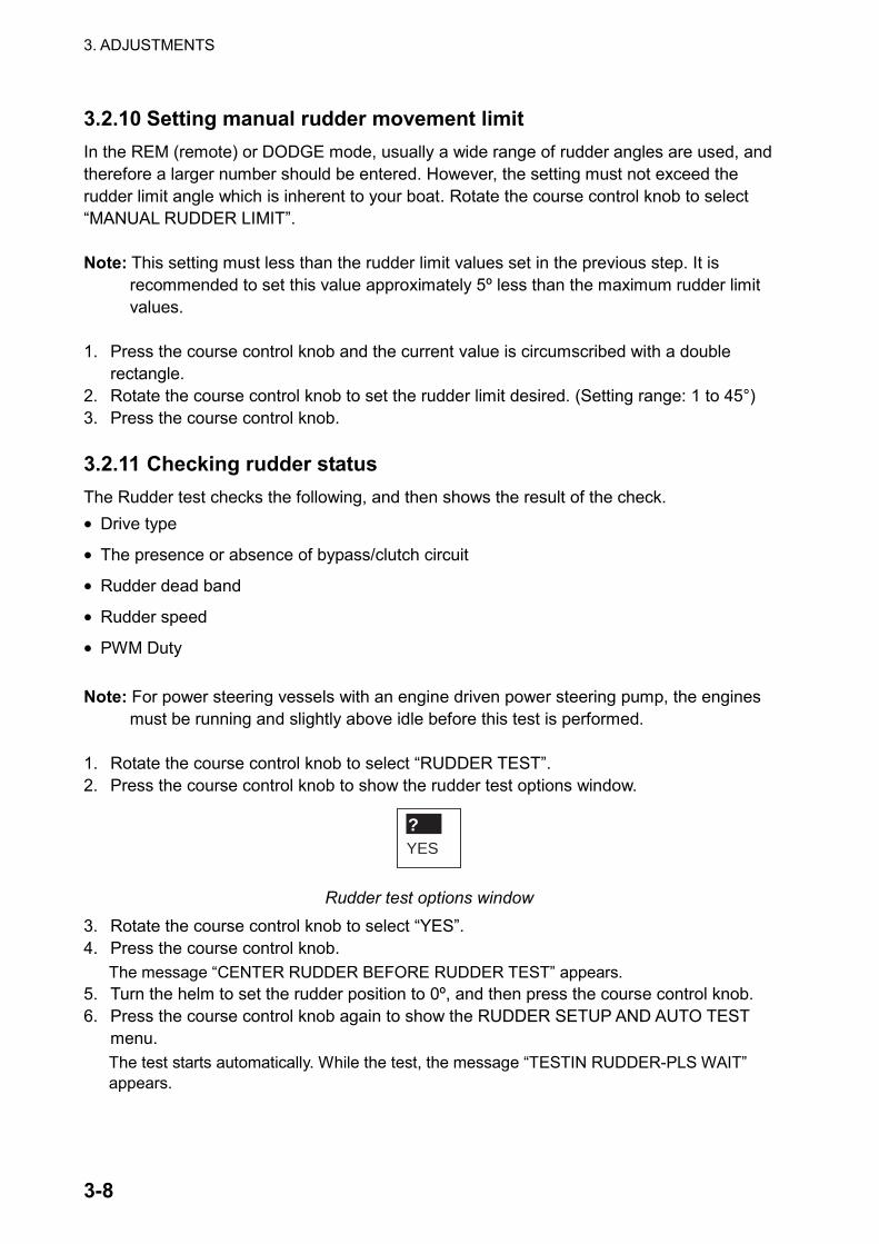
YES?
Rudder test options window
3. Rotate the course control knob to select “YES”. 4. Press the course control knob.
The message “CENTER RUDDER BEFORE RUDDER TEST” appears. 5. Turn the helm to set the rudder position to 0º, and then press the course control knob. 6. Press the course control knob again to show the RUDDER SETUP AND AUTO TEST
menu. The test starts automatically. While the test, the message “TESTIN RUDDER-PLS WAIT” appears.
3. ADJUSTMENTS
3-9
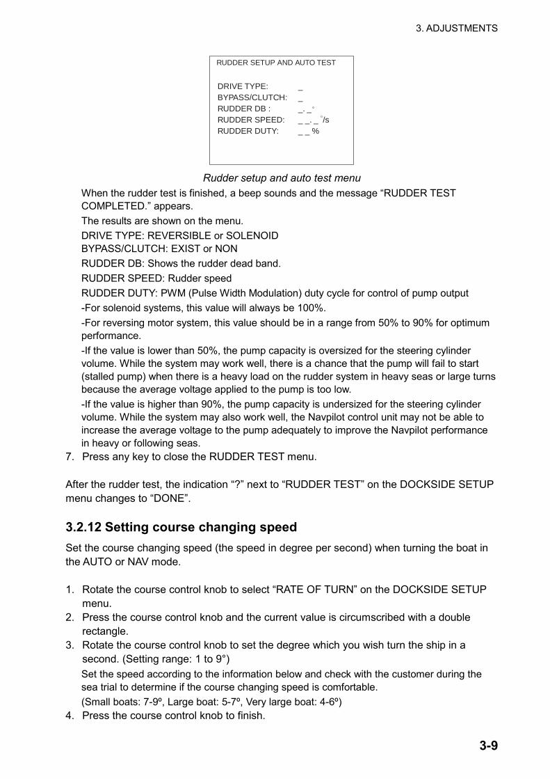
RUDDER SETUP AND AUTO TEST
DRIVE TYPE: _BYPASS/CLUTCH: _RUDDER DB : _. _RUDDER SPEED: _ _. _ /sRUDDER DUTY: _ _ %
Rudder setup and auto test menu
When the rudder test is finished, a beep sounds and the message “RUDDER TEST COMPLETED.” appears. The results are shown on the menu. DRIVE TYPE: REVERSIBLE or SOLENOID BYPASS/CLUTCH: EXIST or NON RUDDER DB: Shows the rudder dead band. RUDDER SPEED: Rudder speed RUDDER DUTY: PWM (Pulse Width Modulation) duty cycle for control of pump output -For solenoid systems, this value will always be 100%. -For reversing motor system, this value should be in a range from 50% to 90% for optimum performance. -If the value is lower than 50%, the pump capacity is oversized for the steering cylinder volume. While the system may work well, there is a chance that the pump will fail to start (stalled pump) when there is a heavy load on the rudder system in heavy seas or large turns because the average voltage applied to the pump is too low. -If the value is higher than 90%, the pump capacity is undersized for the steering cylinder volume. While the system may also work well, the Navpilot control unit may not be able to increase the average voltage to the pump adequately to improve the Navpilot performance in heavy or following seas.
7. Press any key to close the RUDDER TEST menu. After the rudder test, the indication “?” next to “RUDDER TEST” on the DOCKSIDE SETUP menu changes to “DONE”. 3.2.12 Setting course changing speed Set the course changing speed (the speed in degree per second) when turning the boat in the AUTO or NAV mode. 1. Rotate the course control knob to select “RATE OF TURN” on the DOCKSIDE SETUP
menu. 2. Press the course control knob and the current value is circumscribed with a double
rectangle. 3. Rotate the course control knob to set the degree which you wish turn the ship in a
second. (Setting range: 1 to 9°) Set the speed according to the information below and check with the customer during the sea trial to determine if the course changing speed is comfortable. (Small boats: 7-9º, Large boat: 5-7º, Very large boat: 4-6º)
4. Press the course control knob to finish.

3. ADJUSTMENTS
3-10
3.2.13 Selecting compass type Select the heading sensor connected to your Navpilot. 1. Rotate the course control knob to select “COMPASS TYPE.” 2. Press the course control knob to show the compass type options window.
PG-1000OTHER
PG-500
Compass type options window 3. Rotate the course control knob to select PG-500, PG-1000 or OTHER depending on the
heading sensor connected. (Use OTHER for connection to a Furuno Satellite Compass or Gyro Compass.) If OTHER is selected, the auto variation compensation and self check function is not available. (Use hybrid or gyro sensor only.)
4. Press the course control knob to finish. 3.2.14 Setting compass baud rate Select the baud rate of the heading sensor connected. 1. Rotate the course control knob to select “COMPASS BAUD RATE”. 2. Press the course control knob to show the compass baud rate options window.
96001920038400
4800
Compass baud rate options window
3. Rotate the course control knob to select the baud rate from among 4800, 9600, 19200 and 38400 bps. For PG-500, select 4800 bps (default setting).
4. Press the course control knob to finish.

3. ADJUSTMENTS
3-11
3.3 SEA TRIAL Menu Now it is time to check if your boat can run a set heading straightly with default steering characteristics, on the open sea. This trial should be conducted in calm water where there is no boat traffic of obstructions. A sea trial can only be performed when the DOCKSIDE SETUP menu has been completed and confirmed. 1. Open the INSTALLATION menu. 2. Rotate the course control knob to select “SEA TRIAL”. 3. Press the course control knob to show the SEA TRIAL menu.
COMPASS CALIBRATION*: MAGNETIC VARIATION:AUTOCOMPASS OFFSET: E 7.0AUTO COMP CAL UPDATE**: OFFSET CENTER RUDDER POSITIONAUTO TUNING: ?RUDDER DEAD BAND: AUTOCOG: T 359.9 HDG: 359.9
?
*: Appears only when selecting "PG-500" or "PG-1000" at COMPASS TYPE on the DOCKSIDE SETUP menu.
**: Appears only when selecting "PG-500" at COMPASS TYPE on the DOCKSIDE SETUP menu.
***: Heading and course are shown here when appropriate data are entered.
PUSH MENU KEY TO RETURN***TO PREVIOUS MENU.
Sea trial menu
3. ADJUSTMENTS
3-12
3.3.1 Calibrating the heading sensor (For PG-500, PG-1000) The COMPASS CALIBRATION activates the automatic magnetic field deviation correction for the PG-500/PG-1000 Heading Sensor. Note 1: It is not necessary to perform any adjustments to locally at the PG-500 or PG-1000
Heading Sensor. Navpilot has full control of these compass sensors. Note 2: This setting is available only when “PG-500” or “PG-1000” is selected at COMPASS
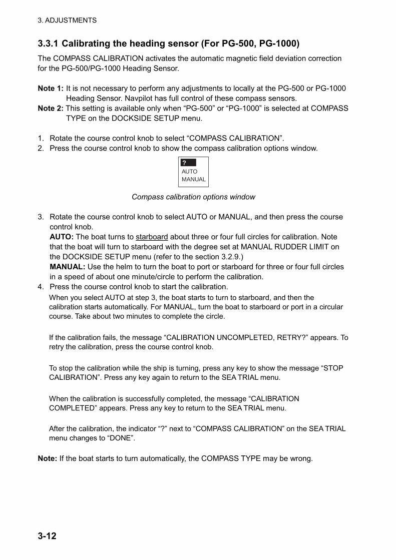
TYPE on the DOCKSIDE SETUP menu. 1. Rotate the course control knob to select “COMPASS CALIBRATION”. 2. Press the course control knob to show the compass calibration options window.
AUTOMANUAL
?
Compass calibration options window
3. Rotate the course control knob to select AUTO or MANUAL, and then press the course
control knob. AUTO: The boat turns to starboard about three or four full circles for calibration. Note that the boat will turn to starboard with the degree set at MANUAL RUDDER LIMIT on the DOCKSIDE SETUP menu (refer to the section 3.2.9.) MANUAL: Use the helm to turn the boat to port or starboard for three or four full circles in a speed of about one minute/circle to perform the calibration.
4. Press the course control knob to start the calibration. When you select AUTO at step 3, the boat starts to turn to starboard, and then the calibration starts automatically. For MANUAL, turn the boat to starboard or port in a circular course. Take about two minutes to complete the circle. If the calibration fails, the message “CALIBRATION UNCOMPLETED, RETRY?” appears. To retry the calibration, press the course control knob. To stop the calibration while the ship is turning, press any key to show the message “STOP CALIBRATION”. Press any key again to return to the SEA TRIAL menu. When the calibration is successfully completed, the message “CALIBRATION COMPLETED” appears. Press any key to return to the SEA TRIAL menu.
After the calibration, the indicator “?” next to “COMPASS CALIBRATION” on the SEA TRIAL menu changes to “DONE”.
Note: If the boat starts to turn automatically, the COMPASS TYPE may be wrong.

3. ADJUSTMENTS
3-13
3.3.2 Using magnetic variation When connecting with a magnetic heading sensor (PG-500 etc.), magnetic variation information is necessary to display true heading data. In almost all cases, a GPS will be connected to the Navpilot and the GPS will send this variation information to the Navpilot automatically. Therefore, please select “AUTO”. In special cases where a manual variation is required, you may input these values manually. Note that this selection only has an effect if you select “TRUE” heading indication for the Navpilot display. Note: If TRUE heading display is selected in the DISPLAY MODE menu, the Navpilot will
display true heading information even though the Navpilot may be connected to a magnetic heading sensor. If TRUE is set, the Navpilot will force the PG-500 to output true heading data in NMEA0183 and AD-10 format to any equipment connected directly. This is very valuable when connecting a Furuno radar FR-21X5 or FR-21X7 series to a Navpilot system because these radars cannot be set for a magnetic heading input and the Waypoint Lolli-pop” will only align properly when running a true heading vessel.
1. Rotate the course control knob to select “MAGNETIC VARIATION”. 2. Press the course control knob to show the magnetic variation options window.
MANUAL
AUTO
Magnetic variation options window
3. Rotate the course control knob to select AUTO or MANUAL. AUTO requires own ship’s position data from the navigator connected.
4. Press the course control knob. When selecting MANUAL, rotate the course control knob to set the variation value, consulting a nautical chart (Setting range: W99.9° to E99.9°).
5. Press the course control knob. 3.3.3 Offsetting the heading data Offset the heading data received from the heading sensor if the heading data shown on the control unit differs from the indication of the ship’s compass. This offset is applied to the heading sensor data. When the control unit shows 125° though the ship’s compass reading is 120°, for example, enter “5°”. 1. Rotate the course control knob to select “COMPASS OFFSET”. 2. Press the course control knob and the current value is circumscribed with a double
rectangle. 3. Rotate the course control knob to set the offset value (Setting range: W180.0° to
E180.0°). 4. Press the course control knob to finish.
3. ADJUSTMENTS
3-14
3.3.4 Automatic distortion compensation (For PG-500) When the magnetic field distortion changes, it can be compensated as follows. Note: This setting is available only when “PG-500” is selected at COMPASS TYPE on the
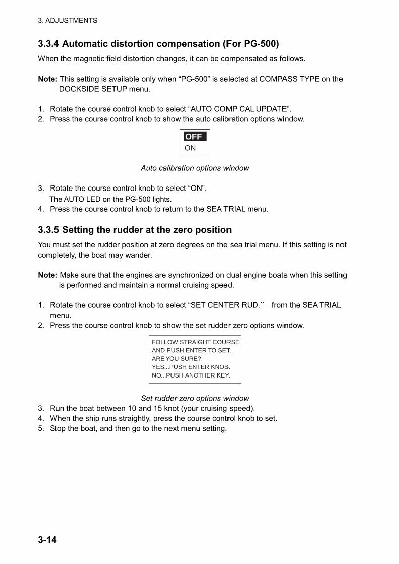
DOCKSIDE SETUP menu. 1. Rotate the course control knob to select “AUTO COMP CAL UPDATE”. 2. Press the course control knob to show the auto calibration options window.
ON
OFF
Auto calibration options window
3. Rotate the course control knob to select “ON”. The AUTO LED on the PG-500 lights.
4. Press the course control knob to return to the SEA TRIAL menu. 3.3.5 Setting the rudder at the zero position You must set the rudder position at zero degrees on the sea trial menu. If this setting is not completely, the boat may wander. Note: Make sure that the engines are synchronized on dual engine boats when this setting
is performed and maintain a normal cruising speed. 1. Rotate the course control knob to select “SET CENTER RUD.” from the SEA TRIAL
menu. 2. Press the course control knob to show the set rudder zero options window.
FOLLOW STRAIGHT COURSEAND PUSH ENTER TO SET.ARE YOU SURE?YES...PUSH ENTER KNOB.NO...PUSH ANOTHER KEY.
Set rudder zero options window 3. Run the boat between 10 and 15 knot (your cruising speed). 4. When the ship runs straightly, press the course control knob to set. 5. Stop the boat, and then go to the next menu setting.

3. ADJUSTMENTS
3-15
3.3.6 Memorizing your boat’s characteristics The automatic tuning enables the Navpilot system to automatically set up the two main steering parameters (rudder gain and counter rudder gain) for the boat. This procedure will shorten the learning time for the self-learning feature. However, if it is difficult to perform this procedure due to limited space or time constraints, this procedure is not necessary and the Navpilot will still fully learn all boat parameters over the course of the first usage. It is not mandatory to perform this procedure as in some other autopilot systems. Do the following procedure in calm water. 1. Confirm that you have enough open water around you, and then run the boat straightly
between 10 and 12 knots straight to windward. 2. Rotate the course control knob to select “AUTO TUNING” from the SEA TRIAL menu. 3. Press the course control knob to show the auto tuning options window.
YES?
Auto tuning options window
4. Rotate the course control knob to select “YES”. 5. Press the course control knob to start the auto tuning.
The boat runs in the AUTO mode. While tuning, the message “AUTO TUNIG – WAIT (**%) appears. When the auto tuning is completed, the message “AUTO TUNING IS COMPLETED” appears. (This tuning takes approx. 5 minutes.)
6. Press any key to finish. After the tuning, the indicator “?” next to “AUTO TUNING” on the SEA TRIAL menu changes to “DONE”.
3.3.7 Setting the rudder dead band You can set the dead band of the rudder automatically or manually. The setting is normally performed automatically during the RUDDER TEST. Manually setting parameter is normally not recommended and may in fact be only useful on older vessels with chain driven or old worn rudder system. 1. Rotate the course control knob to select “RUDDER DEAD BAND” from the SEA TRIAL
menu. 2. Press the course control knob to show the rudder dead band options window.
MANAUTO
Rudder dead band options window
3. Rotate the course control knob to choose “AUTO” or “MAN”. AUTO: Use the rudder dead band automatically detected by the RUDDER TEST on the
DOCK SIDE SETUP menu. MAN: You can enter the appropriate value. (Setting range: 0.1 to 5.0º)
4. Press the course control knob to return to the SEA TRIAL menu.

3. ADJUSTMENTS
3-16
3.4 DISPLAY SETUP Menu The DISPLAY SETUP menu allows you to choose units of measurement. 1. Open the INSTALLATION menu. 2. Rotate the course control knob to select “DISPLAY SETUP”. 3. Press the course control knob to show the display setup menu.
SPEED UNIT:
RANGE UNIT: nm
WIND SPEED UNIT: kt
DEPTH UNIT: ft
WATER TEMP UNIT: F
POSITION FORMAT: DD MM. MMM"
HEADING DISPLAY: MAGNETIC
DATE FORMAT: MMM. DD. YYYY
TIME FORMAT: 24HOUR
kt
DATA BOX FORMAT: 2 BOXES
PUSH MENU KEY TO RETURN
TO PREVIOUS MENU.
Display setup menu
To change pages, select “▼NEXT PAGE” or “▲PREVIOUS PAGE” and press the course control knob.
4. Rotate the course control knob to select the item desired. 5. Press the course control knob to show the speed unit options window. The example
below shows the speed unit options.
km/hMPH
kt
Speed unit options window, for example

3. ADJUSTMENTS
3-17
6. Rotate the course control knob to select option. See the table shown below detailed information.
7. Press the course control knob to finish.
Item Description Settings Speed Unit Choose unit of ship’s speed measurement. kt, km/h, MPH
Range Unit Choose unit of range measurement.
nm, km, sm, nm & yd (YARD appears in TURN menu), nm & m, km & m, sm & yd
Wind Speed Unit Choose unit of wind speed measurement. kt, km/h, m/s, MPH Depth Unit Choose unit of depth measurement. ft, m, FA, P/B (Passi/Braza)
Water Temp Unit Choose unit of water temperature measurement.
°F, °C
Position Format Choose how many digits (or seconds) to display after decimal point in latitude and longitude position.
DD°MM.MM’, DD°MM.MMM’, DD°MM.MMMM’, DD°MM’ SS.S”
Next Page Previous PAGE Heading Readout
Choose heading display format. Magnetic, True
Date Format Choose the date display format. DD. MMM. YYYY, YYYY. MM. DD, MMM. DD. YYYY
Time Display Choose the time display format. 12 HOUR, 24 HOUR Data Box Format Choose the type of the data display. 1 BOX/2 BOXES
3. ADJUSTMENTS
3-18
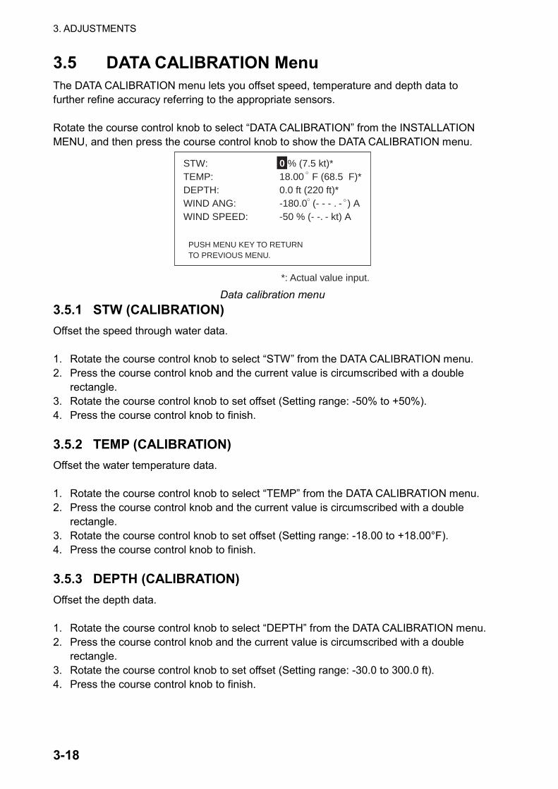
3.5 DATA CALIBRATION Menu The DATA CALIBRATION menu lets you offset speed, temperature and depth data to further refine accuracy referring to the appropriate sensors. Rotate the course control knob to select “DATA CALIBRATION” from the INSTALLATION MENU, and then press the course control knob to show the DATA CALIBRATION menu.
PUSH MENU KEY TO RETURNTO PREVIOUS MENU.
*: Actual value input.
STW: 0 % (7.5 kt)*TEMP: 18.00 F (68.5 F)*DEPTH: 0.0 ft (220 ft)*WIND ANG: -180.0 (- - - . - ) AWIND SPEED: -50 % (- -. - kt) A
Data calibration menu
3.5.1 STW (CALIBRATION) Offset the speed through water data. 1. Rotate the course control knob to select “STW” from the DATA CALIBRATION menu. 2. Press the course control knob and the current value is circumscribed with a double
rectangle. 3. Rotate the course control knob to set offset (Setting range: -50% to +50%). 4. Press the course control knob to finish. 3.5.2 TEMP (CALIBRATION) Offset the water temperature data. 1. Rotate the course control knob to select “TEMP” from the DATA CALIBRATION menu. 2. Press the course control knob and the current value is circumscribed with a double
rectangle. 3. Rotate the course control knob to set offset (Setting range: -18.00 to +18.00°F). 4. Press the course control knob to finish. 3.5.3 DEPTH (CALIBRATION) Offset the depth data. 1. Rotate the course control knob to select “DEPTH” from the DATA CALIBRATION menu. 2. Press the course control knob and the current value is circumscribed with a double
rectangle. 3. Rotate the course control knob to set offset (Setting range: -30.0 to 300.0 ft). 4. Press the course control knob to finish.
3. ADJUSTMENTS
3-19
3.5.4 WIND ANG (angle) (CALIBRATION) Offset the wind angle. (For sailboat only) 1. Rotate the course control knob to select “WIND ANG” from the DATA CALIBRATION
menu. 2. Press the course control knob and the current value is circumscribed with a double
rectangle. 3. Rotate the course control knob to set offset (Setting range: -180.0 to +180.0º). 4. Press the course control knob to finish. 3.5.5 WIND SPEED (CALIBRATION) Offset the wind speed. (For sailboat only.) 1. Rotate the course control knob to select “WIND SPEED” from the DATA CALIBRATION
menu. 2. Press the course control knob and the current value is circumscribed with a double
rectangle. 3. Rotate the course control knob to set offset (Setting range: -50 to +50%) 4. Press the course control knob to finish.
3. ADJUSTMENTS
3-20
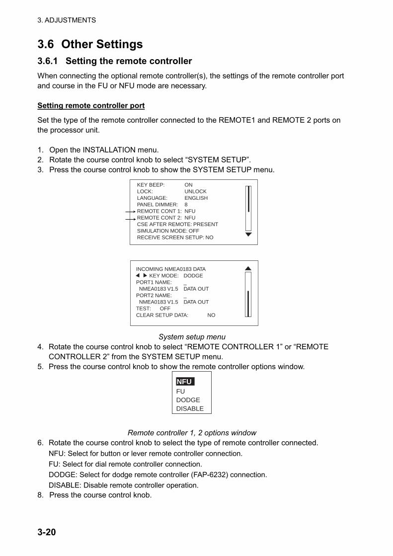
3.6 Other Settings 3.6.1 Setting the remote controller When connecting the optional remote controller(s), the settings of the remote controller port and course in the FU or NFU mode are necessary. Setting remote controller port
Set the type of the remote controller connected to the REMOTE1 and REMOTE 2 ports on the processor unit. 1. Open the INSTALLATION menu. 2. Rotate the course control knob to select “SYSTEM SETUP”. 3. Press the course control knob to show the SYSTEM SETUP menu.
KEY BEEP: ONLOCK: UNLOCKLANGUAGE: ENGLISHPANEL DIMMER: 8REMOTE CONT 1: NFUREMOTE CONT 2: NFUCSE AFTER REMOTE: PRESENTSIMULATION MODE: OFFRECEIVE SCREEN SETUP: NO
INCOMING NMEA0183 DATA KEY MODE: DODGEPORT1 NAME: _ NMEA0183 V1.5 DATA OUTPORT2 NAME: _ NMEA0183 V1.5 DATA OUTTEST: OFFCLEAR SETUP DATA: NO
System setup menu 4. Rotate the course control knob to select “REMOTE CONTROLLER 1” or “REMOTE
CONTROLLER 2” from the SYSTEM SETUP menu. 5. Press the course control knob to show the remote controller options window.
Remote controller 1, 2 options window
6. Rotate the course control knob to select the type of remote controller connected. NFU: Select for button or lever remote controller connection. FU: Select for dial remote controller connection. DODGE: Select for dodge remote controller (FAP-6232) connection. DISABLE: Disable remote controller operation.
8. Press the course control knob.
FUDODGEDISABLE
NFU

3. ADJUSTMENTS
3-21
Selecting course after the REMOTE mode is off
When the remote controller is turned off while in the AUTO mode, the “COURSE AFTER REMOTE” mode can be chosen as shown below. 1. Rotate the course control knob to select “CSE AFTER REMOTE”, and then press it to
show the course after remote options window.
PRESENT COURSE
PREVIOUS COURSE
Course after remote options window
PREVIOUS (COURSE): The previous course before using the remote controller. PRESENT (COURSE): The heading at the moment the remote controller is turned off.
Previous course
New course
Remote controller: OFF Remote
controller: ON
PRESENT COURSE mode
Remote controller: ON
Remote controller: OFF
Previous course
PREVIOUS COURSE mode Course after remote controller is turned off
2. Rotate the course control knob to select PRESENT (COURSE) or PREVIOUS
(COURSE) as appropriate. 3. Press the course control knob. Selecting the language to display
You can select the language to show on the display as follows. 1. Rotate the course control knob to select “LANGUAGE”, and then press it to show the
language options window. 2. Rotate the course control knob to select a language appropriately. 3. Press the course control knob.
3. ADJUSTMENTS
3-22
3.6.2 NMEA port setup Setting the name for port
You can set the name for each port to distinguish them. This name will be used to select the navigation source. 1. Open the SYSTEM SETUP menu referring the previous paragraph. 2. Rotate the course control knob to select “PORT1 NAME” or “PORT 2 NAME.” 3. Press the course control knob. 4. Use the course control knob to enter the name desired.
To move the cursor, press the PORT or STBD key appropriately. 5. Press the MENU key to finish. Setting the NMEA format
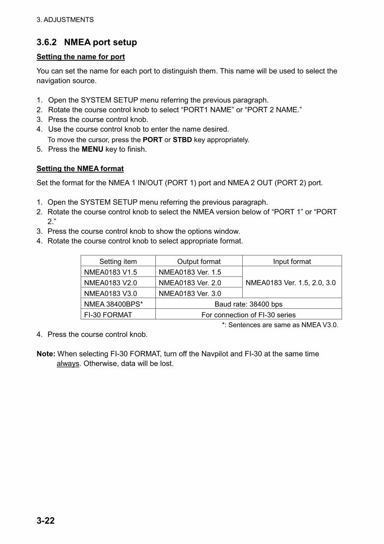
Set the format for the NMEA 1 IN/OUT (PORT 1) port and NMEA 2 OUT (PORT 2) port. 1. Open the SYSTEM SETUP menu referring the previous paragraph. 2. Rotate the course control knob to select the NMEA version below of “PORT 1” or “PORT
2.” 3. Press the course control knob to show the options window. 4. Rotate the course control knob to select appropriate format.
Setting item Output format Input format NMEA0183 V1.5 NMEA0183 Ver. 1.5 NMEA0183 V2.0 NMEA0183 Ver. 2.0 NMEA0183 V3.0 NMEA0183 Ver. 3.0
NMEA0183 Ver. 1.5, 2.0, 3.0
NMEA 38400BPS* Baud rate: 38400 bps FI-30 FORMAT For connection of FI-30 series
*: Sentences are same as NMEA V3.0. 4. Press the course control knob. Note: When selecting FI-30 FORMAT, turn off the Navpilot and FI-30 at the same time
always. Otherwise, data will be lost.
3. ADJUSTMENTS
3-23
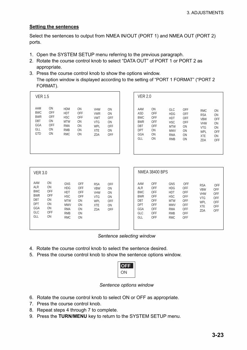
Setting the sentences
Select the sentences to output from NMEA IN/OUT (PORT 1) and NMEA OUT (PORT 2) ports. 1. Open the SYSTEM SETUP menu referring to the previous paragraph. 2. Rotate the course control knob to select “DATA OUT” of PORT 1 or PORT 2 as
appropriate. 3. Press the course control knob to show the options window.
The option window is displayed according to the setting of “PORT 1 FORMAT” (“PORT 2 FORMAT).
AAM ONBWC OFFBWR OFFDBT ONGGA OFFGLL ONGTD ON
HDM ONHDT OFFHSC OFFMTW ONRMA ONRMB ONRMC ON
VHW ONVWR ONVWT OFFVTG ONWPL OFFXTE ONZDA OFF
AAM ONASD OFFBWC OFFBWR OFFDBT OFFDPT ONGGA ONGLL ON
GLC OFFHDG OFFHDT OFFHSC OFFMTW ONMWV ONRMA ONRMB ON
RMC ONRSA ONVBW OFFVHW ONVTG ONWPL OFFXTE ONZDA OFF
AAM ONALR ONBWC OFFBWR OFFDBT ONDPT ONGGA ONGLC OFFGLL ON
GNS OFFHDG OFFHDT OFFHSC OFFMTW ONMWV ONRMA ONRMB ONRMC ON
RSA OFFVBW ONVHW ONVTG ONWPL OFFXTE ONZDA OFF
AAM OFFALR OFFBWC OFFBWR OFFDBT OFFDPT OFFGGA OFFGLC OFFGLL OFF
GNS OFFHDG OFFHDT OFFHSC OFFMTW OFFMWV OFFRMA OFFRMB OFFRMC OFF
RSA OFFVBW OFFVHW OFFVTG OFFWPL OFFXTE OFFZDA OFF
VER 1.5 VER 2.0
VER 3.0 NMEA 38400 BPS
Sentence selecting window
4. Rotate the course control knob to select the sentence desired. 5. Press the course control knob to show the sentence options window.
ON
OFF
Sentence options window
6. Rotate the course control knob to select ON or OFF as appropriate. 7. Press the course control knob. 8. Repeat steps 4 through 7 to complete. 9. Press the TURN/MENU key to return to the SYSTEM SETUP menu.
3. ADJUSTMENTS
3-24
Using sentences selected on other control unit
You can use the display settings selected on other control unit. 1. Open the SYSTEM SETUP menu. 2. Rotate the course control knob to select “RECEIVE SCREN SETUP NO”. 3. Press the course control knob to show the optional window. 4. Rotate the course control knob to select the control unit No. from which you want to
copy settings. 5. Press the course control knob. Confirming the input sentences
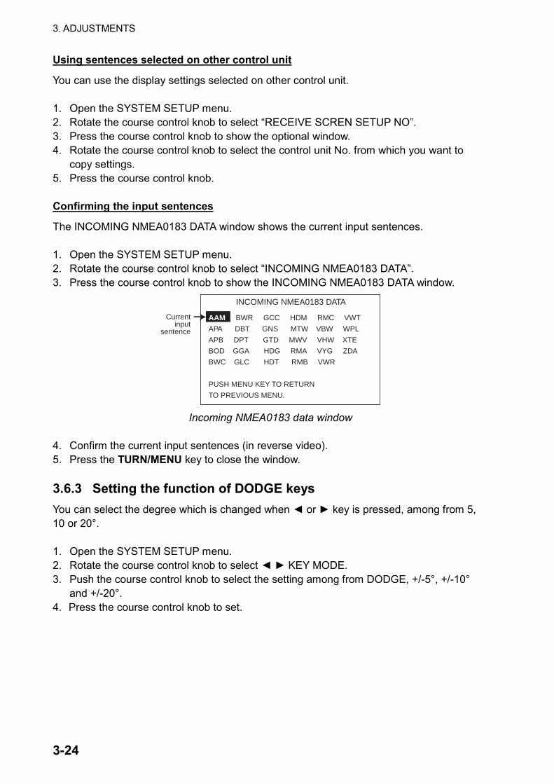
The INCOMING NMEA0183 DATA window shows the current input sentences. 1. Open the SYSTEM SETUP menu. 2. Rotate the course control knob to select “INCOMING NMEA0183 DATA”. 3. Press the course control knob to show the INCOMING NMEA0183 DATA window.
INCOMING NMEA0183 DATA
AAM BWR GCC HDM RMC VWT
APA DBT GNS MTW VBW WPL
APB DPT GTD MWV VHW XTE
BOD GGA HDG RMA VYG ZDA
BWC GLC HDT RMB VWR
PUSH MENU KEY TO RETURN
TO PREVIOUS MENU.
Currentinput
sentence
Incoming NMEA0183 data window
4. Confirm the current input sentences (in reverse video). 5. Press the TURN/MENU key to close the window. 3.6.3 Setting the function of DODGE keys You can select the degree which is changed when ◄ or ► key is pressed, among from 5, 10 or 20°. 1. Open the SYSTEM SETUP menu. 2. Rotate the course control knob to select ◄ ► KEY MODE. 3. Push the course control knob to select the setting among from DODGE, +/-5°, +/-10°
and +/-20°. 4. Press the course control knob to set.
3. ADJUSTMENTS
3-25
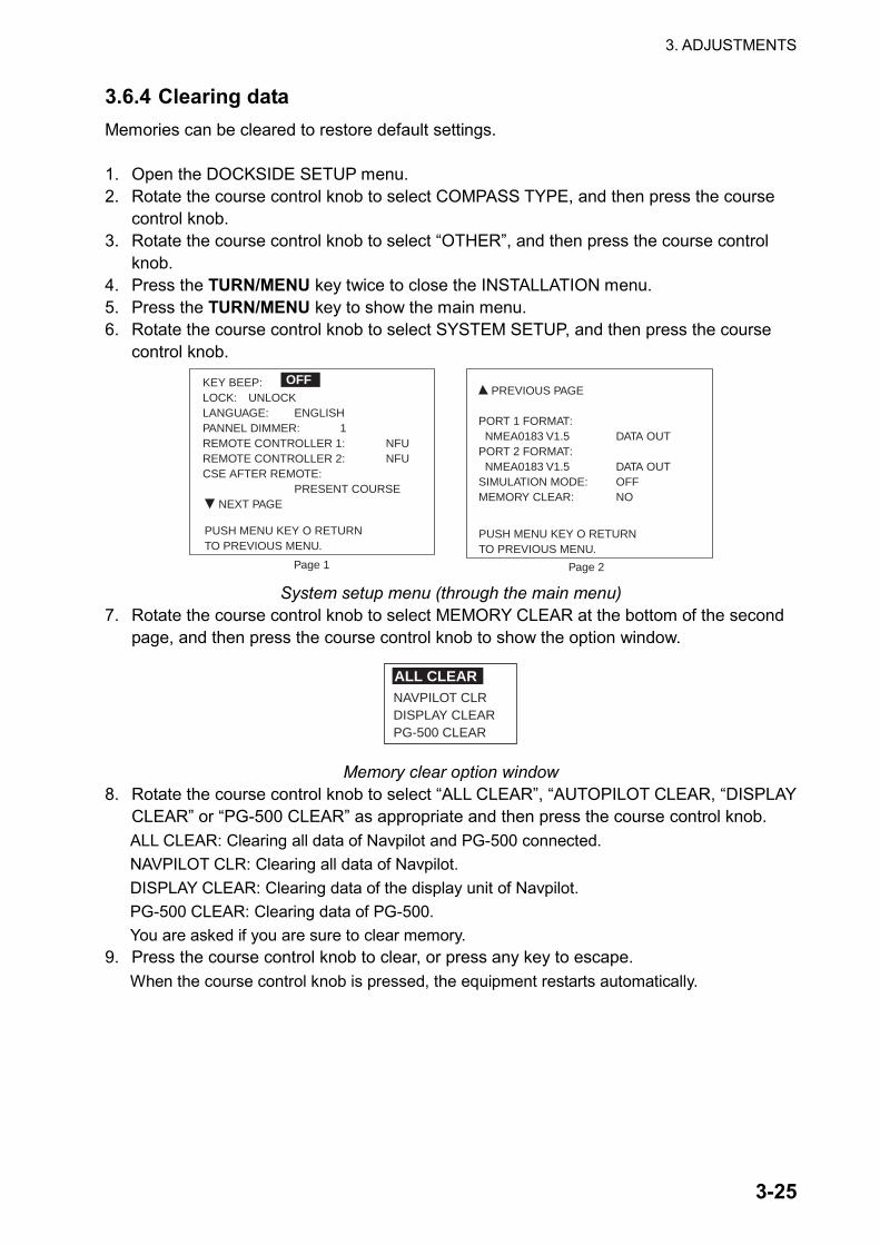
3.6.4 Clearing data Memories can be cleared to restore default settings. 1. Open the DOCKSIDE SETUP menu. 2. Rotate the course control knob to select COMPASS TYPE, and then press the course
control knob. 3. Rotate the course control knob to select “OTHER”, and then press the course control
knob. 4. Press the TURN/MENU key twice to close the INSTALLATION menu. 5. Press the TURN/MENU key to show the main menu. 6. Rotate the course control knob to select SYSTEM SETUP, and then press the course
control knob.
KEY BEEP:LOCK: UNLOCKLANGUAGE: ENGLISHPANNEL DIMMER: 1REMOTE CONTROLLER 1: NFUREMOTE CONTROLLER 2: NFUCSE AFTER REMOTE:
PRESENT COURSE NEXT PAGE
OFF PREVIOUS PAGE
PORT 1 FORMAT: NMEA0183 V1.5 DATA OUTPORT 2 FORMAT: NMEA0183 V1.5 DATA OUTSIMULATION MODE: OFFMEMORY CLEAR: NO
Page 1 Page 2
PUSH MENU KEY O RETURNTO PREVIOUS MENU.
PUSH MENU KEY O RETURNTO PREVIOUS MENU.
System setup menu (through the main menu)
7. Rotate the course control knob to select MEMORY CLEAR at the bottom of the second page, and then press the course control knob to show the option window.
NAVPILOT CLRDISPLAY CLEARPG-500 CLEAR
ALL CLEAR
Memory clear option window 8. Rotate the course control knob to select “ALL CLEAR”, “AUTOPILOT CLEAR, “DISPLAY
CLEAR” or “PG-500 CLEAR” as appropriate and then press the course control knob. ALL CLEAR: Clearing all data of Navpilot and PG-500 connected. NAVPILOT CLR: Clearing all data of Navpilot. DISPLAY CLEAR: Clearing data of the display unit of Navpilot. PG-500 CLEAR: Clearing data of PG-500. You are asked if you are sure to clear memory.
9. Press the course control knob to clear, or press any key to escape. When the course control knob is pressed, the equipment restarts automatically.
3. ADJUSTMENTS
3-26
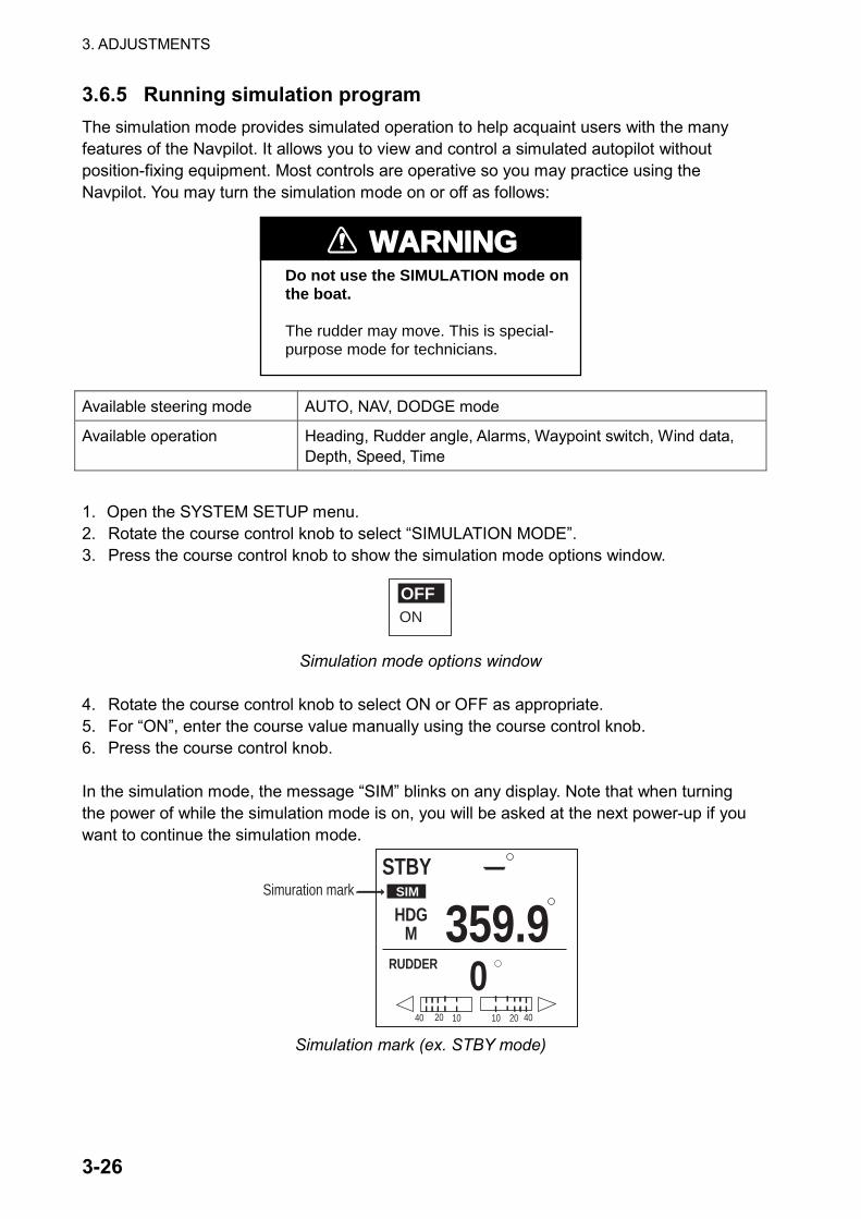
3.6.5 Running simulation program The simulation mode provides simulated operation to help acquaint users with the many features of the Navpilot. It allows you to view and control a simulated autopilot without position-fixing equipment. Most controls are operative so you may practice using the Navpilot. You may turn the simulation mode on or off as follows:
WARNINGDo not use the SIMULATION mode on the boat.
The rudder may move. This is special-purpose mode for technicians.
Available steering mode AUTO, NAV, DODGE mode
Available operation Heading, Rudder angle, Alarms, Waypoint switch, Wind data, Depth, Speed, Time
1. Open the SYSTEM SETUP menu. 2. Rotate the course control knob to select “SIMULATION MODE”. 3. Press the course control knob to show the simulation mode options window.
ON
OFF
Simulation mode options window
4. Rotate the course control knob to select ON or OFF as appropriate. 5. For “ON”, enter the course value manually using the course control knob. 6. Press the course control knob. In the simulation mode, the message “SIM” blinks on any display. Note that when turning the power of while the simulation mode is on, you will be asked at the next power-up if you want to continue the simulation mode.
STBY
359.9RUDDER
HDGM
040 20 10 402010
Simuration mark SIM
Simulation mark (ex. STBY mode)
NAME
OUTLINE
Q'TY
DESCRIPTION/CODE №
PA
CK
ING
L
IST
64AZ-X-9854-0
NAVPILOT-611 (2A)
1/1
NAME
OUTLINE
Q'TY
DESCRIPTION/CODE №
ユニ
ット
UNIT
制御部
PROCESSOR UNIT
FAP-5002-611
000-013-357-00
1
操作部一式箱詰品
CONTROL UNIT COMPLETE SET
FAP-6011
000-013-354-00
1
追従発信器
RUDDER REFERRENCE UNIT
FAP-6112-200
000-090-589-00
1
制御
部予
備品
PROCESSOR UNIT SPARE PARTS
SP64-01401
ヒューズ
GLASS TUBE FUSE
FGMB 125V 4A PBF
000-157-482-10
2
制御
部工
材PROCESSOR UNIT INSTALLATION MATERIALS
CP64-02210
+トラスタッピンネジ 1シュ
SELF-TAPPING SCREW
5X20 SUS304
000-162-608-10
4
ケーブル組品MJ
CABLE ASSY.
MJ-A7SPF0010-150C
000-159-682-10
1
コンベックス
CABLE
TIE
CV-150N
000-162-186-10
40
追従
発信
器工材
RUDDER REFERRENCE UNIT INSTALLATION MATERIALS
CP64-02601
+トラスタッピンネジ 1シュ
SELF-TAPPING SCREW
4X20 SUS304
000-158-850-10
3
バネ座金
SPRING WASHER
M6 SUS304
000-158-855-10
2
ミガキ平座金
FLAT WASHER
M6 SUS304
000-158-854-10
6
ロッドエンドベアリング
ROD END BEARING
RBT6
000-158-846-10
2
嵩上げスペーサ
SPACER
64-024-4612-0
100-328-110-10
1
連結棒
CONNECTING ROD
64-024-4606-0
100-328-060-10
1
六角ナット 1シュ
HEX.NUT
M6 SUS304
000-158-856-10
4
六角ボルト
HEXAGONAL HEAD BOLT
M6X40 SUS304
000-158-853-10
2
図書
DOCUMENT
REFERENCE MANUAL
WIND MODE REFERENCE MANUAL
E72-00401-*
000-151-656-1*
1
装備要領書(英)
INSTALLATION MANUAL (EN)
IME-72730-*
000-169-356-1*
1
(略
図の
寸法
は、
参考
値です
。 DIMENSIONS IN DRAWING FOR REFERENCE ONLY.)
64AZ-X-9854
型式
/コー
ド番
号が
2段
の場
合、
下段
より
上段
に代
わる
過渡
期品
であ
り、
どち
らか
が入
って
いま
す。
な
お、
品質
は変
わり
ませ
ん。
TW
O T
YP
ES
AN
D C
OD
ES M
AY B
E L
ISTED
FO
R A
N ITEM
. T
HE L
OW
ER
PR
OD
UC
T M
AY B
E S
HIP
PED
IN
P
LA
CE O
F T
HE U
PP
ER
PR
OD
UC
T. Q
UA
LIT
Y IS T
HE S
AM
E.
PACKING LIST 64AZ-X-9857 -0
FAP-6011
N A M E O U T L I N E DESCRIPTION/CODE № Q'TY
1/1
ユニット UNIT
操作部
CONTROL UNITFAP-6011
000-013-355-00
1
付属品 ACCESSORIES FP64-01301
コネクタ終端器
TERMINATION PLUGMJ-A7SPF0011
000-147-017-00
1
工事材料 INSTALLATION MATERIALS CP64-02700
+ナベタッピンネジ 1シュ
SELF-TAPPING SCREW3X20 SUS304
000-163-884-10
4
Sマウントスポンジ
SPONGE64-030-1003-0
100-347-480-10
1
ケーブル組品MJ
CABLE ASSY.MJ-A7SPF0010-100C
000-159-681-10
1
図書 DOCUMENT
フラッシュマウント型紙
FLUSH MOUNTING TEMPLATEC72-00802-* ワ/エイ
000-169-360-1*
1
取扱説明書(英)
OPERATOR'S MANUAL(EN)OME-72501-*
000-148-603-1*
1
操作要領書(英)
OPERATOR'S GUIDE(EN)OSE-72501-*
000-148-604-1*
1
(略図の寸法は、参考値です。 DIMENSIONS IN DRAWING FOR REFERENCE ONLY.) 64AZ-X-9857
型式/コード番号が2段の場合、下段より上段に代わる過渡期品であり、どちらかが入っています。 なお、品質は変わりません。
TWO TYPES AND CODES MAY BE LISTED FOR AN ITEM. THE LOWER PRODUCT MAY BE SHIPPED IN PLACE OF THE UPPER PRODUCT. QUALITY IS THE SAME.
30/Jun/08 R.Esumi
30/Jun/08 R.Esumi


1 2 4 5 63
B
A
D
C
NAME
名称
TITLE
kgMASS
DWG No.
SCALE
APPROVED
CHECKED
DRAWN
REF.No.INTERCONNECTION DIAGRAM
相互結線図
NAVpilot-611
オートパイロット
AUTOPILOT
64-030-5001-0
T.YAMASAKI
C7275-C01- A
123456
+12V
SHIELD 7GND
WHTBLUYELGRNREDBLK
シロアオキミドリアカクロ
P_SWGND
TB9 MJ-A7SPF MJ-A7SPF*2CONTROL A
123456
+12V
SHIELD 7GND
WHTBLUYELGRNREDBLK
シロアオキミドリアカクロ
P_SWGND
CAN2-ACAN2-B
TB10CONTROL B
J2MJ-A7SPF001210m,φ6
123456SHIELD
GND
BLUYELGRN
アオキミドリ
REDアカチャ BRN
TB11REM1-P
REM1-SIGREM1-N
REM1-SW
12345
TB13RRU_P
RRU-SIG1RRU_SIG2
RRU_NSHIELD
GRNミドリYELキ
クロシロ WHT
BLK
REM A
RRU
J2 71234567
MJ-A7SPF J1MJ-A7SPF*2J2
MJ-A7SPF001210m,φ6
CONTROL UNIT操作部
FAP-5001/6011
GND
PWR_SW-HPWR_SW-CCAN-ACAN-B
C_GND
12V_P
7
123456GND
PWR_SW-HPWR_SW-C
CAN-ACAN-B
C_GND
12V_P
J1
GND
PWR_SW-HPWR_SW-CCAN-ACAN-B
C_GND
12V_P
7
123456
J1MJ-A7SPF
1234567
GND
PWR_SW-HPWR_SW-CCAN-ACAN-B
C_GND
12V_PGND
PWR_SW-HPWR_SW-C
CAN-ACAN-B
C_GND
12V_P
7
123456
12m
10m
FAP-5552REMOTE CONTROLLER遠隔管制器
RUDDER REFERENCE追従発信器
UNIT FAP-6112
MJ-A7SPF0010,10m,φ6
MJ-A7SPF0010,10m,φ6
同上DITTO
12
TB1(+)(-)
123 GND
SOL-B/MOTOR-SOL-A/MOTOR+TB2
12-24VDC
123
TB3B/C_POWERB/CSHIELD
456
EXT_BUZZ-AEXT_BUZZ-BSHIELD
123456
J1
123456
MJ-A6SPF
MJ-A6SPF J2
SOLENOID VALVE
REVERSIBLE PUMP
電磁弁
外部アラームEXTERNAL ALARM
HYDRAULIC LINERDRIVE
クラッチ
RELAY CONTACT (MAX.3A)
FAP-5002PROCESSOR UNIT制御部
*1IV-1.25sq.
123456
TB8HD_IN-AHD_IN-BHD_OUT-AHD_OUT-B+12V
SHIELD7GND
MJ-A7SPF0010,10m,φ6
HDG
1234567
J3
GND+12V
SHIELD
TD-ATD-BRD-HRD-C
MJ-A7SPF
ヘディングセンサーHEADING SENSORPG-500
WHTBLUYELGRNREDBLK
シロアオキミドリアカクロ
SHIELDNC
TD-ATD-BRD-HRD-C
SHIELDNC
SHIFT-HSHIFT-C
DATA-HDATA-C
RADAR(AD-10 FORMAT)
レーダー
航法装置NAV. EQUIPMENT(NMEA FORMAT)
12/24 VDC
REMOTE CONTROLLERFAP-6232
遠隔管制器REMOTE CONTROLLER遠隔管制器
FAP-6212/6222
*2: OPTION.
*1IV-1.25sq.
MJ-A6SPF0003,5m,φ612345
TB7NMEA_OUT1-ANMEA_OUT1-BNMEA_IN1-ANMEA_IN1-BSHIELD
12345 SHIELD
TB6POWERGNDNMEA_OUT2-ANMEA_OUT2-B
*2
123456
NMEA1 IN/OUT
NMEA2 OUT
12345 SHIELD
TB5POWERGNDNMEA_IN2-ANMEA_IN2-B
P
12345 SHIELD
TB4TDRDGNDNC
GND
RXDTXD
DTRDSRRTSCTS
(RS-232C)
RS232C
航法装置
マルチディスプレイMULTI DISPLAYRD-30
1234
NMEA2 IN
NAV EQUIPMENT
TD-HTD-C
P
YELGRN
キミドリ
WHTシロクロ BLK
7
56
SENSORセンサー
NCSHIELD
TXD-HTXD-CRXD-HRXD-C
RD-HRD-C
+VGNDFG
PCパソコン
P
P
アカクロ
REDBLK
MJ-A7SPF0009,2m,φ6*2
BLUWHTシロ
アオキ YELミドリ GRN
TD-ATD-B
12-24VDC
TERMINATOR終端器
MJ-A7SPF0011
GND
PWR_SW-HPWR_SW-CCAN-ACAN-B
C_GND
J1
12V_P
7
123456
PHR-7
FAP-5021CONTROL UNIT操作部
1234567
J2
GND
PWR_SW-HPWR_SW-C
CAN-ACAN-B
C_GND
12V_P
CONTROL UNIT操作部
FAP-5001/6011 MJ-A7SPF
*2
接続箱
FAP-6821BOXJUNCTION J1 7
MJ-A7SPF10m,φ7
MJ-A7SPF0015-100C,10m,φ7
P
P
123456SHIELD
GND
MJ-A10SPF0002,10m,φ61
5
78910
MJ-A10SPF
326
4
J1モモ/アカキ/アカモモ/クロミズ/クロミズ/アカ
YEL/REDPNK/BLK
L-BLU/BLKL-BLU/RED
PNK/REDTB12 REMOTE CONTROLLER
FAP-5551
遠隔管制器*2REM B
1
5
78910
MJ-A10SPFJ2-J4
326
4
REM-PREM-SIG
REM-NREM-SWREM-COM
NCNCNCNCFG
REM-PREM-SIGREM-NREM-SWREM-COMNCNCNCNCFG
REMOTE CONTROLLER遠隔管制器
REMOTE CONTROLLER遠隔管制器
FAP-6211/6221 FAP-6231
操作部操作部FAP-5001/6011FAP-5001/6011
CONTROL UNITCONTROL UNIT
T.TAKENO
DISTRIBUTOR分配器FAP-6800
*1IV-1.25sq.
*1IV-1.25sq.
*1IV-1.25sq.
CAN1-ACAN1-B
REM2-PREM2-SIG
REM2-NREM2-SW
SOL-ASOL-B
SOL-COM
SOL-ASOL-B
MOTOR+MOTOR-
BYPASS/CLUTCH+BYPASS/CLUTCH-
リバーシブルポンプ
*1: SHIPYARD SUPPLY.
NOTE
*2)オプション。
*1)造船所手配。
注記
*3)ケーブル長さにより芯線の太さを変更する。
*3: CHANGE THE CORE SIZE ACCORDING TO CABLE LENGTH.
DPY-1.5
DPY-2.5
DPY-2.5
TPY-2.5,MAX.5m
DPY-2.5,MAX.5m*1 *3
*1 *3
*1 *3
*1 *3
*1 *3
24/Jul/08
4/Aug/08
5/Aug/08 R.Esumi