autonomous surface marker buoy - florida...
TRANSCRIPT

30th Florida Conference on Recent Advances in Robotics May 11-12, 2017, Florida Atlantic University, Boca Raton, Florida
Autonomous Surface Marker Buoy
Hailey Armstrong, Justin Bryan, Kyle Muir, Juan Rothe
Florida Atlantic University 777 Glades Rd
Boca Raton, FL 33431
[email protected], [email protected], [email protected], [email protected]
ABSTRACT The main objective of this engineering design project is to replace the traditional diving surface marker buoy (SMB) which alerts nearby boaters that a diver is in the area. The traditional surface marker buoy has a tether that can get caught in reefs or other objects which can be dangerous. The design presented in this paper eliminates the use of the traditional tether making it safer for the free-diver. The autonomous surface marker communicates with a diver device wirelessly through radio, travels close to the diver’s last known surface location, and keeps this location until a new one is received. A dive-band determines the diver’s GPS coordinates when the diver is on the surface and transmits them to the autonomous surface vehicle (ASV). The ASV determines its GPS location and compares it to the diver’s location. It then determines its instantaneous heading and compares it to the desired heading to calculate the most efficient way to travel to the diver. The ASV is controlled by sending individual duty cycles to two motor drivers. These motor drivers then send RC signals to their respective thrusters which controls the rotational speed of each thruster individually. This creates varying thrusts which causes forward, backward, and turning movements. After multiple tests, the optimal thruster algorithm was created and the autonomous surface vehicle successfully traveled to the diver’s location. The accuracy of the system could be improved upon by purchasing more accurate sensors if given a larger budget. Keywords Surface marker Buoy (SMB), Autonomous surface vehicle (ASV), Electronic speed controllers (ESCs)
1. INTRODUCTION Freediving is a sport/hobby practiced all around the world and is very similar to scuba diving. The difference is that in scuba diving, there is an oxygen tank that allows the diver to breathe underwater which eliminates the need for frequent resurfacing. When free diving, the diver relies on their own skill and physical abilities to hold their breath until they resurface. One additional possibility is that the diver uses a snorkel which eliminates the need for complete resurfacing. Free diving has become very popular recently, and the industry continues to grow each year due to its connection with many activities such as spearfishing, photography, snorkeling, etc. The ocean covers most the earth’s surface and free divers are not the only ones in the ocean, which is a reason why it can be a dangerous sport/hobby to practice. Today, free divers utilize a diving buoy that
is known as a surface marker buoy (SMB). On this buoy, there is a flag or sign that indicates to others that divers are in the area and in some cases a flashing battery powered light [1]. The problem with this type of surface marker is that the buoy is tethered to the diver, meaning that the diver is constantly dragging the marker around, which is not only tedious but dangerous. This tether can become entangled or caught by underwater features which can lead to injury or death. An example of the traditional SMB can be seen below in Figure 1.
Figure 1: Basic Design of Dive Buoy [2]
Recently, there has been a lot of interest in autonomous vehicles for research and recreational purposes. These vehicles are driverless and are capable of maneuvering along a surface or a body of water. This peaked interest is shown in an influx of recent patents and journal articles relating to the subject. These patents include devices capable of utilizing GPS [3] [4] [5] [6] [7] [8] [9] [10] [11] [12], wireless communication devices [13] [14] [15] [16] [5] [7] [11] [17], and position sensors [18] [19] [6] [7] [9] [10] [12]. One useful application for an autonomous vehicle is to combine these components to create an autonomous surface vehicle (ASV) which can track a free diver’s movements. This eliminates the need for the dangerous tether while increasing the possible applications. A simple way to control an ASV with two thrusters is through electric propulsion. This is the norm in small, remotely controlled boats [20]. This allows the motors revolutions per minute (rpm) to be easily adjusted through a pulse width modulated (PWM) signal and a speed controller. This speed controller converts the PWM signal into a pulse width control signal (PWC) that controls the speed and direction of the rotation. With being able to control the
30th Florida Conference on Recent Advances in Robotics May 11-12, 2017, Florida Atlantic University, Boca Raton, Florida
speed and direction of each thruster independently, it allows for the direction of travel to be altered without the use of a rudder. This report will detail a design that will protect all recreational free divers from the hazards of using the traditional SMB. This new idea, besides providing protection to the diver just like the existing SMB, can maintain two-way communication between the buoy and diver without a physical presence of an attachment, such as a tether, as well as providing the possibility for useful devices to be attached to the platform. This device looks more like a mini pontoon boat than a traditional dive buoy. It can follow the diver around autonomously. The basic breakdown of the system is as follows. The diver will wear a device that will send GPS coordinates through radio frequencies to the buoy every time the diver resurfaces. After the GPS coordinates have been received, the buoy will send a confirmation signal back to the diver’s device which will alert the diver it is safe to submerge again. As soon as the buoy receives the diver’s position, it will immediately determine the most efficient path to get to the location and begin moving.
1.1 Problem Conceptualization and Definition The traditional SMB is tethered to the diver, and this creates a problem with safety. The diver can easily become entangled on an object such as a reef or a boat propeller. This could cause devastating results such as serious injury or death. The design presented in this report is to be operated under minimal wind, wave, and cloud cover. This will prevent tipping of the ASV as well as quick and accurate GPS location reception. The problem is to replace the traditional SMB with an autonomous surface marker that can efficiently travel to a free diver’s surface locations and maintain the most recent position while the diver is submerged. This diver-buoy system will not be physically connected which will increase the safety of the system.
1.2 Project Objectives and Goals The overall goal of this design project is to move a diver’s flag safely and efficiently to a diver’s most recent surface location and hold this position until the diver resurfaces. The objectives of this project are: The device should sense its own GPS location and be able to distinguish its relative heading when compared to another GPS coordinate. The device should be able to efficiently move from its original position to an established GPS coordinate (with an error of 15 feet). The device should be able to maintain the last known diver surface position while the diver is underwater as well as obtain and move to the diver’s newest surface location once the diver surfaces.
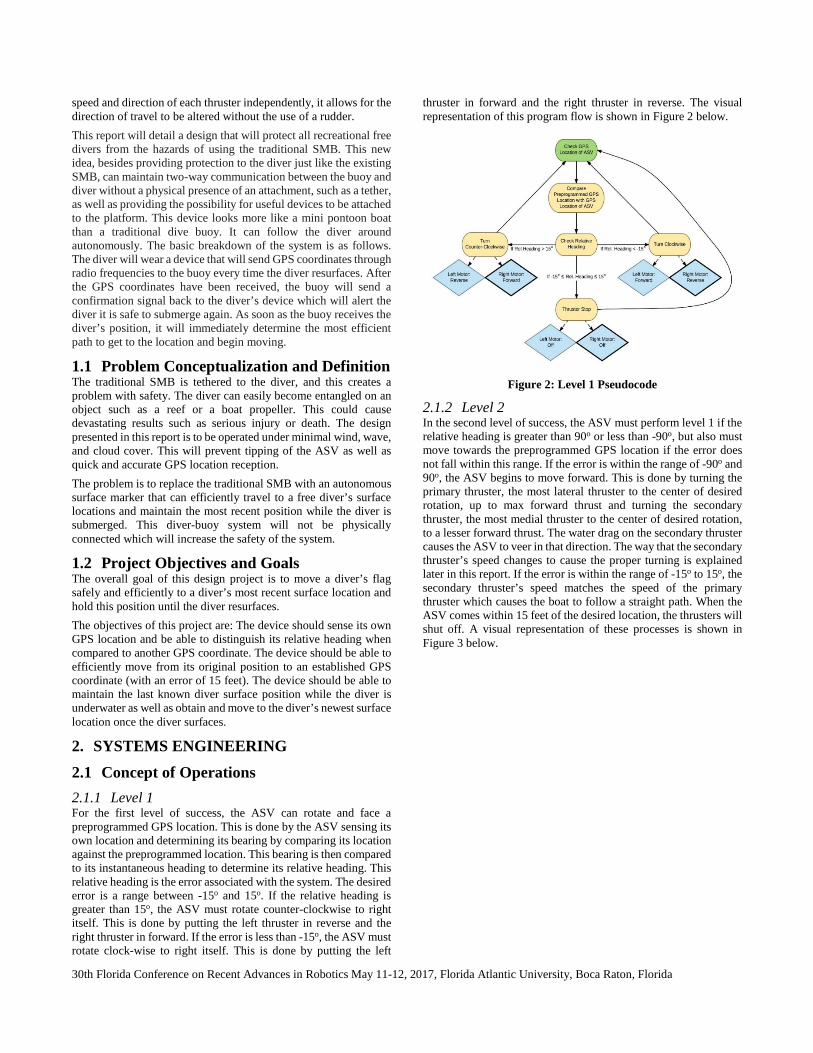
2. SYSTEMS ENGINEERING 2.1 Concept of Operations 2.1.1 Level 1 For the first level of success, the ASV can rotate and face a preprogrammed GPS location. This is done by the ASV sensing its own location and determining its bearing by comparing its location against the preprogrammed location. This bearing is then compared to its instantaneous heading to determine its relative heading. This relative heading is the error associated with the system. The desired error is a range between -15o and 15o. If the relative heading is greater than 15o, the ASV must rotate counter-clockwise to right itself. This is done by putting the left thruster in reverse and the right thruster in forward. If the error is less than -15o, the ASV must rotate clock-wise to right itself. This is done by putting the left
thruster in forward and the right thruster in reverse. The visual representation of this program flow is shown in Figure 2 below.
Figure 2: Level 1 Pseudocode
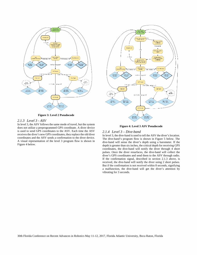
2.1.2 Level 2 In the second level of success, the ASV must perform level 1 if the relative heading is greater than 90o or less than -90o, but also must move towards the preprogrammed GPS location if the error does not fall within this range. If the error is within the range of -90o and 90o, the ASV begins to move forward. This is done by turning the primary thruster, the most lateral thruster to the center of desired rotation, up to max forward thrust and turning the secondary thruster, the most medial thruster to the center of desired rotation, to a lesser forward thrust. The water drag on the secondary thruster causes the ASV to veer in that direction. The way that the secondary thruster’s speed changes to cause the proper turning is explained later in this report. If the error is within the range of -15o to 15o, the secondary thruster’s speed matches the speed of the primary thruster which causes the boat to follow a straight path. When the ASV comes within 15 feet of the desired location, the thrusters will shut off. A visual representation of these processes is shown in Figure 3 below.
30th Florida Conference on Recent Advances in Robotics May 11-12, 2017, Florida Atlantic University, Boca Raton, Florida
Figure 3: Level 2 Pseudocode
2.1.3 Level 3 - ASV In level 3, the ASV follows the same mode of travel, but the system does not utilize a preprogrammed GPS coordinate. A diver device is used to send GPS coordinates to the ASV. Each time the ASV receives the diver’s new GPS coordinates, they replace the old diver coordinates and the ASV sends a confirmation to the diver device. A visual representation of the level 3 program flow is shown in Figure 4 below.
Figure 4: Level 3 ASV Pseudocode
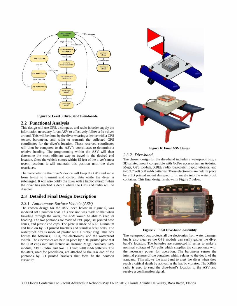
2.1.4 Level 3 – Dive-band In level 3, the dive-band is used to tell the ASV the diver’s location. The dive-band’s program flow is shown in Figure 5 below. The dive-band will sense the diver’s depth using a barometer. If the depth is greater than six inches, the critical depth for receiving GPS coordinates, the dive-band will notify the diver through 4 short pulses. Once the diver resurfaces, the dive-band will collect the diver’s GPS coordinates and send them to the ASV through radio. If the confirmation signal, described in section 2.1.3 above, is received, the dive-band will notify the diver using 2 short pulses. But if the confirmation is not received within 8 seconds, signifying a malfunction, the dive-band will get the diver’s attention by vibrating for 3 seconds.
30th Florida Conference on Recent Advances in Robotics May 11-12, 2017, Florida Atlantic University, Boca Raton, Florida
Figure 5: Level 3 Dive-Band Pseudocode
2.2 Functional Analysis This design will use GPS, a compass, and radio in order supply the information necessary for an ASV to effectively follow a free diver around. This will be done by the diver wearing a device with a GPS sensor, barometer, and radio to transmit the collected GPS coordinates for the diver’s location. These received coordinates will then be compared to the ASV’s coordinates to determine a relative heading. The programming within the ASV will then determine the most efficient way to travel to the desired end location. Once the vehicle comes within 15 feet of the diver’s most recent location, it will maintain this position until the diver resurfaces. The barometer on the diver’s device will keep the GPS and radio from trying to transmit and collect data while the diver is submerged. It will also notify the diver with a haptic vibrator when the diver has reached a depth where the GPS and radio will be disabled
2.3 Detailed Final Design Description 2.3.1 Autonomous Surface Vehicle (ASV) The chosen design for the ASV, seen below in Figure 6, was modeled off a pontoon boat. This decision was made so that when traveling through the water, the ASV would be able to keep its heading. The two pontoons are made of PVC pipe, 3D printed nose cones, and plastic end caps. The plate is made of 6061 aluminum and held on by 3D printed brackets and stainless steel bolts. The waterproof box is made of plastic with a rubber ring. This box houses the batteries, ESCs, the electronics, and the waterproof switch. The electronics are held in place by a 3D printed plate that the PCB clips into and include an Arduino Mega, compass, GPS module, XBEE radio, and two 11.1 volt 6200 mAh batteries. The thrusters, used for propulsion, are attached to the rear end of the pontoons by 3D printed brackets that form fit the pontoon curvature.
Figure 6: Final ASV Design
2.3.2 Dive-band The chosen design for the dive-band includes a waterproof box, a 3D printed mount compatible with GoPro accessories, an Arduino Mega, GPS module, XBEE radio, barometer, haptic vibrator, and two 3.7 volt 500 mAh batteries. These electronics are held in place by a 3D printed mount designed to fit snugly into the waterproof container. This final design is shown in Figure 7 below.
Figure 7: Final Dive-band Assembly
The waterproof box protects all the electronics from water damage, but is also clear so the GPS module can easily gather the dive-band’s location. The batteries are connected in series to make a nominal voltage of 7.4 volts which supplies the components with the necessary power for operation. The barometer senses the internal pressure of the container which relates to the depth of the armband. This allows the arm band to alert the diver when they reach a critical depth by activating the haptic vibrator. The XBEE radio is used to send the dive-band’s location to the ASV and receive a confirmation signal.

30th Florida Conference on Recent Advances in Robotics May 11-12, 2017, Florida Atlantic University, Boca Raton, Florida
2.4 Requirements and Constraints 2.4.1 Requirements The requirements for the Engineering Design course are that the senior design projects have at least two actuators and at least two sensors. This project has three actuators (the two thrusters, and the haptic vibrator) and six sensors (the two Radio XBee sensors, the two GPS sensors, the digital compass, the barometer).
2.4.1.1 Level 1 The ASV can sense its own GPS location and rotate itself clockwise or counter-clockwise to face a preprogrammed GPS coordinate by comparing its compass heading with the desired heading.
2.4.1.2 Level 2 In addition to the level 1 requirements, the ASV will can travel from its original location to the preprogrammed GPS coordinate efficiently. Once at this position, the ASV can adequately compensate for external forces (wind, current, etc.) to maintain this position.
2.4.1.3 Level 3 In addition to the level 2 requirements, the ASV’s desired GPS coordinates will be updated with the diver’s new position while the diver is on the surface of the water.
2.4.2 Constraints
2.4.2.1 Weather, Wind and Current The operation of this project will occur in winds under 4 mph and in seas with minimal waves/current as well as on a clear day where the GPS coordinates are easily collected.
2.4.2.2 Budget The total cost paid for by the school will not exceed $500.
2.4.2.3 Operation Time between Charges The design will not be used for periods lasting more than 1 hour without recharging fully. The dive-band will die before the ASV.
2.4.3 Assumptions
2.4.3.1 Underwater Travel Distance Diver will not travel a distance that exceeds the radio’s range before resurfacing.
2.4.3.2 Resurfacing Procedure Diver will follow safety protocols when resurfacing (i.e. Rising out of water with arm pointed at the sky.) which will help with collecting new GPS coordinates as well as reestablishing connection with the ASV.
2.4.3.3 Line of Sight and Obstructions There will be no other objects in the water that could impact the ASV or obstruct the line of sight between the ASV and diver.
2.4.3.4 Water depth The water depth that the ASV is operating in is deep enough to where it will not run aground.
2.5 Management Plan 2.5.1 Machining and Assembly Both the ASV and dive-band were initially designed in Solidworks. They are both made of parts that were manufactured as well as 3D
printed. All machining and assembly was completed by Kyle Muir and Juan Rothe.
2.5.1.1 ASV Overall Assembly The overall assembly started with a simple PVC pipe that was shortened to the desired length of twenty-four inches. An aluminum metal sheet was used as the base of the ASV. Nose cones, thruster mounts, plate brackets, and a PCB mount were all 3D printed to precisely fit the unique design dimensions. The thruster mounts, plate brackets, and nose cones were attached to the PVC pipe with plastic epoxy glue in the interior and on the exterior. This process was done carefully to prevent any possible leaks. The epoxy was later sanded various times with different grades of sand paper to achieve a smooth finish that makes the pontoon look like a single piece. These sealed pontoons were then painted and protected with multiple matte finish coats.
2.5.1.2 Dive-Band Overall Assembly The overall assembly of the dive-band was done using a 3D printed GoPro mount and acquired waterproof box. Using the supplied head strap GoPro mount, the printed mount easily attached to it using a screw. The printed GoPro mount was attached to the waterproof box using epoxy. The overall dive-band assembly is light and is easily worn on the divers head.
2.5.2 Electrical Design Hailey Armstrong and Justin Bryan did the electrical design of the system. Juan Rothe designed the printed circuit board. Help was received from the electronics lab personnel, John Kielbasa, Ed Henderson and Adam Prey, whenever questions about problems that could not be solved arose.
2.5.2.1 Wiring Diagrams
2.5.2.1.1 ASV
Figure 8: ASV Wiring Diagram
2.5.2.1.2 Dive-Band
30th Florida Conference on Recent Advances in Robotics May 11-12, 2017, Florida Atlantic University, Boca Raton, Florida
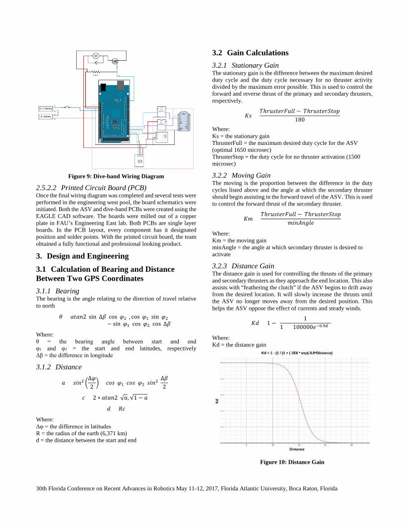
Figure 9: Dive-band Wiring Diagram
2.5.2.2 Printed Circuit Board (PCB) Once the final wiring diagram was completed and several tests were performed in the engineering west pool, the board schematics were initiated. Both the ASV and dive-band PCBs were created using the EAGLE CAD software. The boards were milled out of a copper plate in FAU’s Engineering East lab. Both PCBs are single layer boards. In the PCB layout, every component has it designated position and solder points. With the printed circuit board, the team obtained a fully functional and professional looking product.
3. Design and Engineering 3.1 Calculation of Bearing and Distance Between Two GPS Coordinates 3.1.1 Bearing The bearing is the angle relating to the direction of travel relative to north
𝜃𝜃 = 𝑎𝑎𝑎𝑎𝑎𝑎𝑎𝑎2(sin (∆𝛽𝛽)cos (𝜑𝜑2), cos (𝜑𝜑1)sin (𝜑𝜑2)− sin (𝜑𝜑1)cos (𝜑𝜑2)cos (∆𝛽𝛽)
Where: θ = the bearing angle between start and end φ1 and φ2 = the start and end latitudes, respectively Δβ = the difference in longitude
3.1.2 Distance
𝑎𝑎 = 𝑠𝑠𝑠𝑠𝑎𝑎2 �∆𝜑𝜑2 � + 𝑐𝑐𝑐𝑐𝑠𝑠(𝜑𝜑1)𝑐𝑐𝑐𝑐𝑠𝑠(𝜑𝜑2)𝑠𝑠𝑠𝑠𝑎𝑎2(
∆𝛽𝛽2 )
𝑐𝑐 = 2 ∗ 𝑎𝑎𝑎𝑎𝑎𝑎𝑎𝑎2(√𝑎𝑎,√1 − 𝑎𝑎)
𝑑𝑑 = 𝑅𝑅𝑐𝑐
Where: Δφ = the difference in latitudes R = the radius of the earth (6,371 km) d = the distance between the start and end
3.2 Gain Calculations 3.2.1 Stationary Gain The stationary gain is the difference between the maximum desired duty cycle and the duty cycle necessary for no thruster activity divided by the maximum error possible. This is used to control the forward and reverse thrust of the primary and secondary thrusters, respectively.
𝐾𝐾𝑠𝑠 =𝑇𝑇ℎ𝑟𝑟𝑟𝑟𝑠𝑠𝑎𝑎𝑟𝑟𝑟𝑟𝑟𝑟𝑟𝑟𝑟𝑟𝑟𝑟 − 𝑇𝑇ℎ𝑟𝑟𝑟𝑟𝑠𝑠𝑎𝑎𝑟𝑟𝑟𝑟𝑟𝑟𝑎𝑎𝑐𝑐𝑟𝑟
180
Where: Ks = the stationary gain ThrusterFull = the maximum desired duty cycle for the ASV (optimal 1650 microsec) ThrusterStop = the duty cycle for no thruster activation (1500 microsec)
3.2.2 Moving Gain The moving is the proportion between the difference in the duty cycles listed above and the angle at which the secondary thruster should begin assisting in the forward travel of the ASV. This is used to control the forward thrust of the secondary thruster.
𝐾𝐾𝐾𝐾 =𝑇𝑇ℎ𝑟𝑟𝑟𝑟𝑠𝑠𝑎𝑎𝑟𝑟𝑟𝑟𝑟𝑟𝑟𝑟𝑟𝑟𝑟𝑟 − 𝑇𝑇ℎ𝑟𝑟𝑟𝑟𝑠𝑠𝑎𝑎𝑟𝑟𝑟𝑟𝑟𝑟𝑎𝑎𝑐𝑐𝑟𝑟
𝐾𝐾𝑠𝑠𝑎𝑎𝑚𝑚𝑎𝑎𝑚𝑚𝑟𝑟𝑟𝑟
Where: Km = the moving gain minAngle = the angle at which secondary thruster is desired to activate
3.2.3 Distance Gain The distance gain is used for controlling the thrusts of the primary and secondary thrusters as they approach the end location. This also assists with “feathering the clutch” if the ASV begins to drift away from the desired location. It will slowly increase the thrusts until the ASV no longer moves away from the desired position. This helps the ASV oppose the effect of currents and steady winds.
𝐾𝐾𝑑𝑑 = 1 − (1
1 + (100000𝑟𝑟−0.9𝑑𝑑))
Where: Kd = the distance gain
Figure 10: Distance Gain

30th Florida Conference on Recent Advances in Robotics May 11-12, 2017, Florida Atlantic University, Boca Raton, Florida
3.3 Thruster Control The autonomous movement of the ASV is obtained through a proportional gain error based controller. The calculations to obtain the gains are listed in section 3.2 above. In this controller design, the thruster that provides the most forward thrust is known as the primary thruster and the other thruster is known as the secondary thruster. These labels switch between thrusters based on the heading and bearing as the ASV travels through the water. If clockwise rotation is needed to reduce the error, the left thruster is the primary and the right is secondary. The opposite is true if counter-clockwise rotation is necessary. As the ASV approaches the desired end location, the distance gain lowers the duty cycles until the thrusters are turned off. This prevents the ASV from colliding with the diver and assists in opposing outside forces such as currents and winds when trying to maintain its location.
3.3.1 Error 𝑟𝑟𝑟𝑟𝑟𝑟𝑐𝑐𝑟𝑟 = |𝑏𝑏𝑟𝑟𝑎𝑎𝑟𝑟𝑠𝑠𝑎𝑎𝑚𝑚 − ℎ𝑟𝑟𝑎𝑎𝑑𝑑𝑠𝑠𝑎𝑎𝑚𝑚|
𝑠𝑠𝑖𝑖 𝑟𝑟𝑟𝑟𝑟𝑟𝑐𝑐𝑟𝑟 > 180 𝑎𝑎ℎ𝑟𝑟𝑎𝑎 𝑟𝑟𝑟𝑟𝑟𝑟𝑐𝑐𝑟𝑟 = 𝑟𝑟𝑟𝑟𝑟𝑟𝑐𝑐𝑟𝑟 − 180
Where: error = the error associated with the system
3.3.2 Stationary Rotation (error > maxAngle) The maxAngle is the angle at which the ASV is to switch between stationary rotation and turning while moving forward. While the error is greater than this maxAngle, the ASV will rotate in place by having one thruster, the primary, provide forward thrust and the other, the secondary thruster, provide a reverse thrust.
3.3.2.1 Primary Thruster 𝑟𝑟𝑠𝑠𝑚𝑚𝑎𝑎𝑎𝑎𝑟𝑟 = 𝑇𝑇ℎ𝑟𝑟𝑟𝑟𝑠𝑠𝑎𝑎𝑟𝑟𝑟𝑟𝑟𝑟𝑎𝑎𝑐𝑐𝑟𝑟 + (1 − 𝐾𝐾𝑑𝑑)(𝐾𝐾𝑠𝑠)(𝑟𝑟𝑟𝑟𝑟𝑟𝑐𝑐𝑟𝑟)
Where: Signal = the duty cycle sent to the electronic speed controller (ESC)
3.3.2.2 Secondary Thruster 𝑟𝑟𝑠𝑠𝑚𝑚𝑎𝑎𝑎𝑎𝑟𝑟 = 𝑇𝑇ℎ𝑟𝑟𝑟𝑟𝑠𝑠𝑎𝑎𝑟𝑟𝑟𝑟𝑟𝑟𝑎𝑎𝑐𝑐𝑟𝑟 − (1 − 𝐾𝐾𝑑𝑑)(𝐾𝐾𝑠𝑠)(𝑟𝑟𝑟𝑟𝑟𝑟𝑐𝑐𝑟𝑟)
3.3.3 Moving (error <maxAngle) Once the error is less than the maxAngle, the ASV will continue turning but will begin moving forward.
3.3.3.1 Error > minAngle The minAngle is the angle at which the secondary thruster will begin providing forward thrust. While the error is greater than this minAngle, the secondary thruster will be turned off and all forward movement and rotation will be provided by the primary thruster and the drag on the secondary thruster.
3.3.3.1.1 Primary Thruster 𝑟𝑟𝑠𝑠𝑚𝑚𝑎𝑎𝑎𝑎𝑟𝑟 = 𝑇𝑇ℎ𝑟𝑟𝑟𝑟𝑠𝑠𝑎𝑎𝑟𝑟𝑟𝑟𝑟𝑟𝑟𝑟𝑟𝑟𝑟𝑟 − 𝐾𝐾𝑑𝑑(𝑇𝑇ℎ𝑟𝑟𝑟𝑟𝑠𝑠𝑎𝑎𝑟𝑟𝑟𝑟𝑟𝑟𝑟𝑟𝑟𝑟𝑟𝑟 − 𝑇𝑇ℎ𝑟𝑟𝑟𝑟𝑠𝑠𝑎𝑎𝑟𝑟𝑟𝑟𝑟𝑟𝑎𝑎𝑐𝑐𝑟𝑟)
3.3.3.1.2 Secondry Thruster 𝑟𝑟𝑠𝑠𝑚𝑚𝑎𝑎𝑎𝑎𝑟𝑟 = 𝑇𝑇ℎ𝑟𝑟𝑟𝑟𝑠𝑠𝑎𝑎𝑟𝑟𝑟𝑟𝑟𝑟𝑎𝑎𝑐𝑐𝑟𝑟
3.3.3.2 Error < minAngle When the error becomes less than the min Angle, the secondary thruster will begin providing a forward thrust. This will slow the ASV’s turning which will prevent overshoot and oscillation during travel. As the error approaches zero, the secondary thruster’s thrust will approach that of the primary thruster. This way, the ASV will travel straight.
3.3.3.2.1 Primary Thruster 𝑟𝑟𝑠𝑠𝑚𝑚𝑎𝑎𝑎𝑎𝑟𝑟 = 𝑇𝑇ℎ𝑟𝑟𝑟𝑟𝑠𝑠𝑎𝑎𝑟𝑟𝑟𝑟𝑟𝑟𝑟𝑟𝑟𝑟𝑟𝑟 − 𝐾𝐾𝑑𝑑(𝑇𝑇ℎ𝑟𝑟𝑟𝑟𝑠𝑠𝑎𝑎𝑟𝑟𝑟𝑟𝑟𝑟𝑟𝑟𝑟𝑟𝑟𝑟 − 𝑇𝑇ℎ𝑟𝑟𝑟𝑟𝑠𝑠𝑎𝑎𝑟𝑟𝑟𝑟𝑟𝑟𝑎𝑎𝑐𝑐𝑟𝑟)
3.3.3.2.2 Secondry Thruster 𝑟𝑟𝑠𝑠𝑚𝑚𝑎𝑎𝑎𝑎𝑟𝑟 = 𝑟𝑟𝑠𝑠𝑚𝑚𝑎𝑎𝑎𝑎𝑟𝑟𝑝𝑝𝑝𝑝𝑝𝑝𝑝𝑝𝑝𝑝𝑝𝑝𝑝𝑝 + (1 − 𝐾𝐾𝑑𝑑)(𝐾𝐾𝐾𝐾)(𝑟𝑟𝑟𝑟𝑟𝑟𝑐𝑐𝑟𝑟)
Where: Signalprimary = the duty cycle sent to the primary thruster’s ESC
3.4 Primary and Secondary Thruster Selection 3.4.1 Heading > Bearing
3.4.1.1 Error >0 If the heading is greater than the bearing and the error is greater than zero, then the ASV must move counter-clockwise to reduce the error. This makes the right thruster the primary thruster and the left the secondary.
3.4.1.2 Error <0 If the heading is greater than the bearing and the error is less than zero, the ASV must move clockwise to reduce the error. This means that the left thruster must be the primary thruster and the right must be the secondary.
3.4.2 Heading < Bearing
3.4.2.1 Error >0 If the heading is less than the bearing and the error is positive, the ASV must move clockwise to reduce the error, this means that the left thruster needs to be the primary thruster and the right thruster must be the secondary
3.4.2.2 Error <0 If the heading is less than the bearing and the error is negative, the ASV must move counter-clockwise to reduce the error. To achieve this the right thruster must be the primary, and the left thruster must be the secondary.
4. Testing and Evaluation 4.1 Individual System, Subsystem, Component Testing Each individual component, such as each sensor, was tested individually before integrating multiple components together. All systems passed in this level of testing for both the ASV and dive-band.
4.2 Systems Integration Testing After individual testing stages passed, multiple combinations of components were made and tested as integrated systems. All system integrations for both the ASV and dive-band passed its testing.
30th Florida Conference on Recent Advances in Robotics May 11-12, 2017, Florida Atlantic University, Boca Raton, Florida
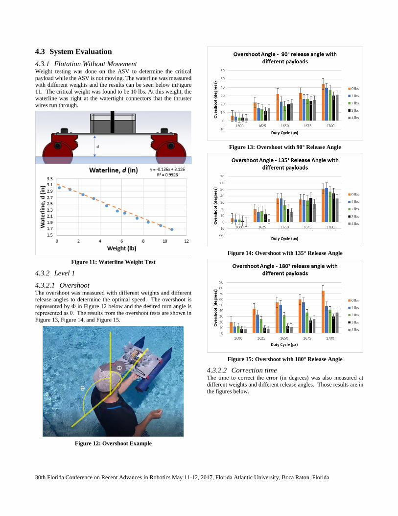
4.3 System Evaluation 4.3.1 Flotation Without Movement Weight testing was done on the ASV to determine the critical payload while the ASV is not moving. The waterline was measured with different weights and the results can be seen below inFigure 11. The critical weight was found to be 10 lbs. At this weight, the waterline was right at the watertight connectors that the thruster wires run through.
Figure 11: Waterline Weight Test
4.3.2 Level 1
4.3.2.1 Overshoot The overshoot was measured with different weights and different release angles to determine the optimal speed. The overshoot is represented by Φ in Figure 12 below and the desired turn angle is represented as θ. The results from the overshoot tests are shown in Figure 13, Figure 14, and Figure 15.
Figure 12: Overshoot Example
Figure 13: Overshoot with 90° Release Angle
Figure 14: Overshoot with 135° Release Angle
Figure 15: Overshoot with 180° Release Angle
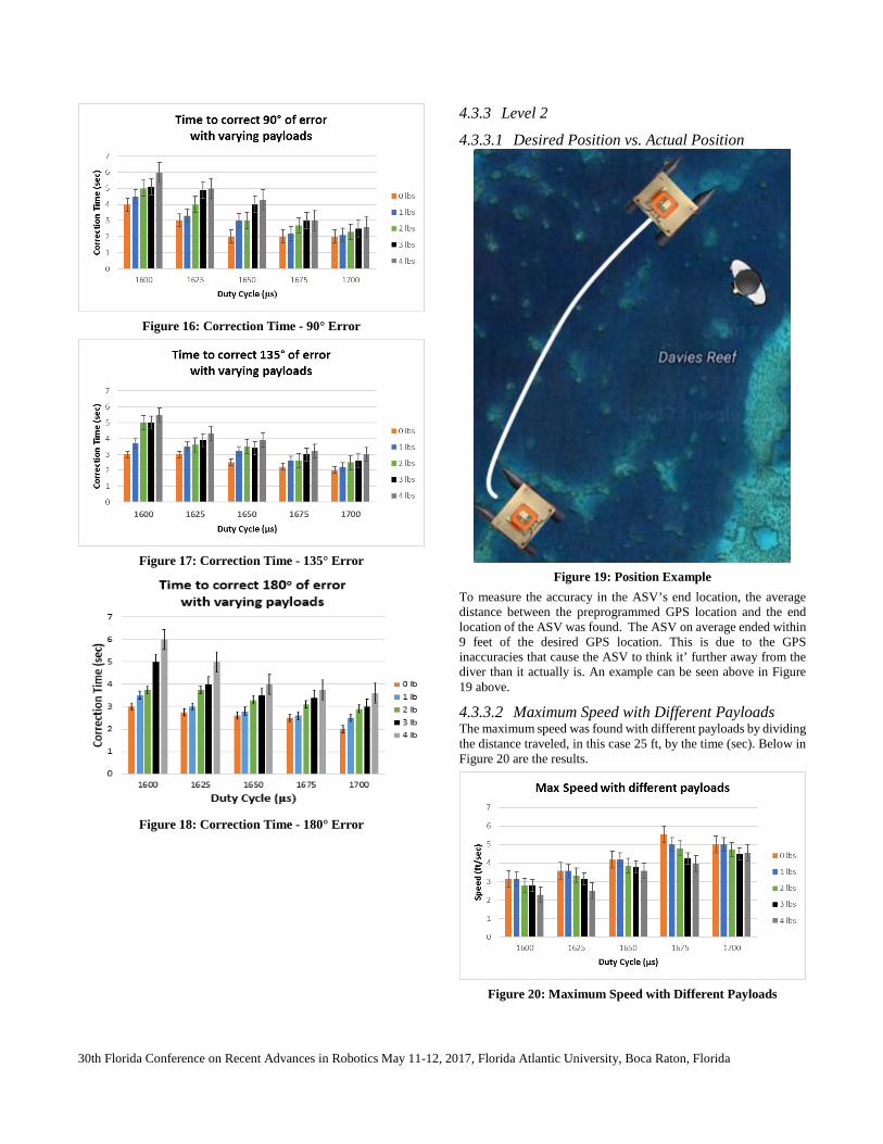
4.3.2.2 Correction time The time to correct the error (in degrees) was also measured at different weights and different release angles. Those results are in the figures below.
30th Florida Conference on Recent Advances in Robotics May 11-12, 2017, Florida Atlantic University, Boca Raton, Florida
Figure 16: Correction Time - 90° Error
Figure 17: Correction Time - 135° Error
Figure 18: Correction Time - 180° Error
4.3.3 Level 2
4.3.3.1 Desired Position vs. Actual Position
Figure 19: Position Example
To measure the accuracy in the ASV’s end location, the average distance between the preprogrammed GPS location and the end location of the ASV was found. The ASV on average ended within 9 feet of the desired GPS location. This is due to the GPS inaccuracies that cause the ASV to think it’ further away from the diver than it actually is. An example can be seen above in Figure 19 above.
4.3.3.2 Maximum Speed with Different Payloads The maximum speed was found with different payloads by dividing the distance traveled, in this case 25 ft, by the time (sec). Below in Figure 20 are the results.
Figure 20: Maximum Speed with Different Payloads
30th Florida Conference on Recent Advances in Robotics May 11-12, 2017, Florida Atlantic University, Boca Raton, Florida
4.3.4 Level 3
4.3.4.1 Confirmation Time To determine how long it took to send and receive a message between the two devices, an Arduino code was written. It was determined that the time ranged from 12 to 56 milliseconds but averaged at 44 seconds.
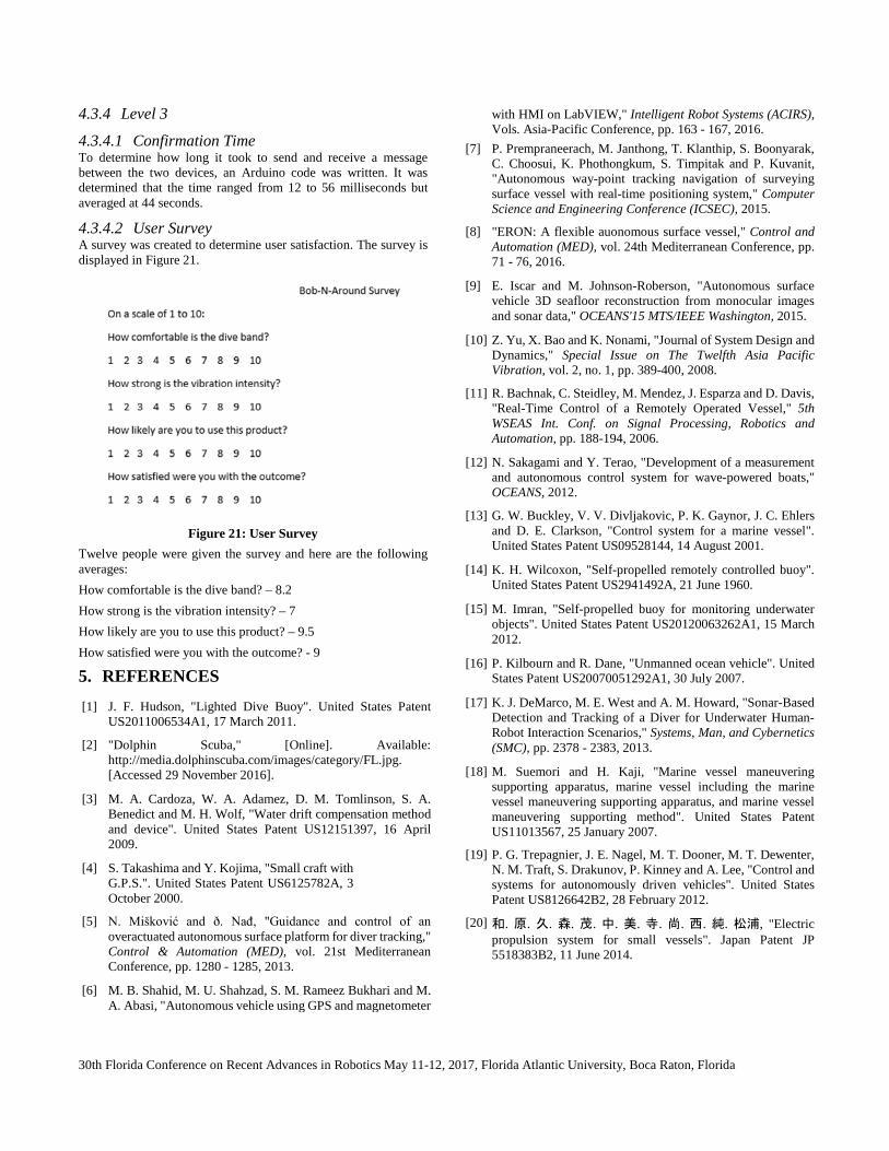
4.3.4.2 User Survey A survey was created to determine user satisfaction. The survey is displayed in Figure 21.
Figure 21: User Survey
Twelve people were given the survey and here are the following averages: How comfortable is the dive band? – 8.2 How strong is the vibration intensity? – 7 How likely are you to use this product? – 9.5 How satisfied were you with the outcome? - 9
5. REFERENCES
[1] J. F. Hudson, "Lighted Dive Buoy". United States Patent US2011006534A1, 17 March 2011.
[2] "Dolphin Scuba," [Online]. Available: http://media.dolphinscuba.com/images/category/FL.jpg. [Accessed 29 November 2016].
[3] M. A. Cardoza, W. A. Adamez, D. M. Tomlinson, S. A. Benedict and M. H. Wolf, "Water drift compensation method and device". United States Patent US12151397, 16 April 2009.
[4] S. Takashima and Y. Kojima, "Small craft with G.P.S.". United States Patent US6125782A, 3 October 2000.
[5] N. Mišković and ð. Nađ, "Guidance and control of an overactuated autonomous surface platform for diver tracking," Control & Automation (MED), vol. 21st Mediterranean Conference, pp. 1280 - 1285, 2013.
[6] M. B. Shahid, M. U. Shahzad, S. M. Rameez Bukhari and M. A. Abasi, "Autonomous vehicle using GPS and magnetometer
with HMI on LabVIEW," Intelligent Robot Systems (ACIRS), Vols. Asia-Pacific Conference, pp. 163 - 167, 2016.
[7] P. Prempraneerach, M. Janthong, T. Klanthip, S. Boonyarak, C. Choosui, K. Phothongkum, S. Timpitak and P. Kuvanit, "Autonomous way-point tracking navigation of surveying surface vessel with real-time positioning system," Computer Science and Engineering Conference (ICSEC), 2015.
[8] "ERON: A flexible auonomous surface vessel," Control and Automation (MED), vol. 24th Mediterranean Conference, pp. 71 - 76, 2016.
[9] E. Iscar and M. Johnson-Roberson, "Autonomous surface vehicle 3D seafloor reconstruction from monocular images and sonar data," OCEANS'15 MTS/IEEE Washington, 2015.
[10] Z. Yu, X. Bao and K. Nonami, "Journal of System Design and Dynamics," Special Issue on The Twelfth Asia Pacific Vibration, vol. 2, no. 1, pp. 389-400, 2008.
[11] R. Bachnak, C. Steidley, M. Mendez, J. Esparza and D. Davis, "Real-Time Control of a Remotely Operated Vessel," 5th WSEAS Int. Conf. on Signal Processing, Robotics and Automation, pp. 188-194, 2006.
[12] N. Sakagami and Y. Terao, "Development of a measurement and autonomous control system for wave-powered boats," OCEANS, 2012.
[13] G. W. Buckley, V. V. Divljakovic, P. K. Gaynor, J. C. Ehlers and D. E. Clarkson, "Control system for a marine vessel". United States Patent US09528144, 14 August 2001.
[14] K. H. Wilcoxon, "Self-propelled remotely controlled buoy". United States Patent US2941492A, 21 June 1960.
[15] M. Imran, "Self-propelled buoy for monitoring underwater objects". United States Patent US20120063262A1, 15 March 2012.
[16] P. Kilbourn and R. Dane, "Unmanned ocean vehicle". United States Patent US20070051292A1, 30 July 2007.
[17] K. J. DeMarco, M. E. West and A. M. Howard, "Sonar-Based Detection and Tracking of a Diver for Underwater Human-Robot Interaction Scenarios," Systems, Man, and Cybernetics (SMC), pp. 2378 - 2383, 2013.
[18] M. Suemori and H. Kaji, "Marine vessel maneuvering supporting apparatus, marine vessel including the marine vessel maneuvering supporting apparatus, and marine vessel maneuvering supporting method". United States Patent US11013567, 25 January 2007.
[19] P. G. Trepagnier, J. E. Nagel, M. T. Dooner, M. T. Dewenter, N. M. Traft, S. Drakunov, P. Kinney and A. Lee, "Control and systems for autonomously driven vehicles". United States Patent US8126642B2, 28 February 2012.
[20] 和. 原. 久. 森. 茂. 中. 美. 寺. 尚. 西. 純. 松浦, "Electric propulsion system for small vessels". Japan Patent JP 5518383B2, 11 June 2014.