automotive selector guide - farnell element14 · 2015-04-23 · automotive selector guide making...
TRANSCRIPT

Automotive Selector Guide
Making embedded systems better with robust reliable performance
Freescale Semiconductor, Inc. Quarter 1, 2015SG187 Rev 57

Co
Analo
e Componentsponents
Page 4Page 5Page 7Page 8Page 8Page 8Page 8Page 10Page 10Page 11Page 12Page 12Page 12Page 14Page 14Page 14Page 15
Powe Page 16Page 17Page 17
SensMAP) Sensors
Page 18Page 18Page 19Page 20
Acce Page 21
LocaSolut
Page 22Page 22
SG187 (Selector Guide) (1Q2015) – 2
ntentsPRODUCTS Sub category
g and Mixed Signal Power Actuation - Low-side SwitchesPower Actuation - High-side SwitchesPower Actuation - H-Bridge and Motors DriversPower Actuation - H-Bridge Stepper MotorsPower Actuation - Pre-Drivers (High-side MOSFET Gate Drivers) Power Actuation - Squib DriversPower Actuation - Powertrain Control and Engine ManagementCommunication Transceivers - CAN Physical Interface ComponentsCommunication Transceivers - LIN, ISO-9141, J-1850 Physical InterfacCommunication Transceiver - Distributed Systems Interface (DSI) ComMillimeter Wave and RadarSignal ConditioningSystem Basis ChipBattery Management - Battery Cell ControllerEmbedded MCU plus Power - S12 Mixed-Signal Analog MCUsS12 Mixed-Signal Analog MCUs8-bit Intelligent Distributed Controllers
r Management Power Management - Linear RegulatorsPower Management - Switching RegulatorsAutomotive Alternator Voltage Regulators
ors Pressure SensorsBarometric Absolute Pressure (BAP) and Manifold Absolute Pressure (Inertial SensorsTire Pressure Monitoring Systems
ss and Remote Control GPS Downconverter
l Interconnect Network (LIN) ions
LIN Software ProductsLIN Physical Layer Transceivers

MC
er Architecture® Technology
Page 24Page 26Page 29Page 31Page 31Page 32Page 33Page 38Page 39Page 40
SG187 (Selector Guide) (1Q2015) – 3
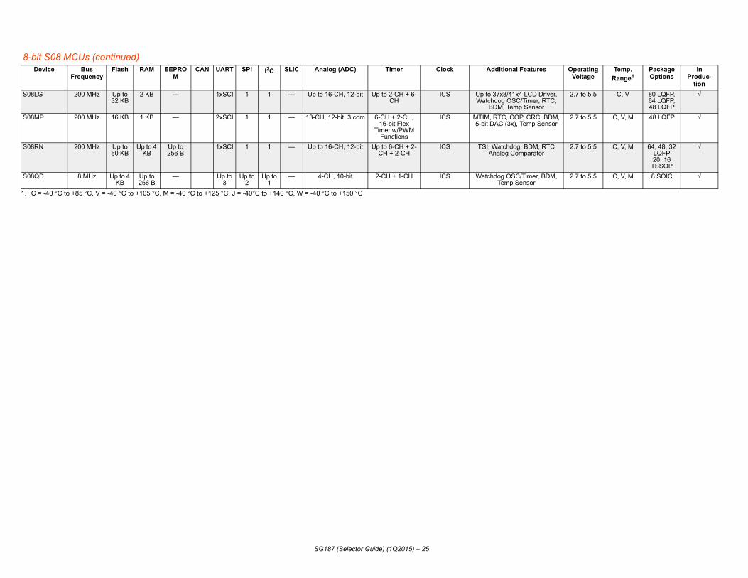
U 8-bit S08 MCUsS12 and S12X FamiliesS12 MagniV Mixed-signal MCUs56F8xxx FamilyKinetis MCUs based on ARM® TechnologyMAC57Dxxx 32-bit ARM®-Based MCUs32-bit Qorivva MPC56xx and MPC57xx MCUs Built on PowImage Cognition Processorsi.MX Applications Processors32-bit Vybrid Controller Solutions
PRODUCTS Sub category

Free
Power Produc
1. Produc
Protection Features Packaging Status
MC33800 Open Load detect, Overcurrent protect, Overvoltage protect, Shorted Load detect, Undervoltage protect,
Thermal protect
54-pin SOICWExposed Pad
Production EVB
MC33810 Shorted Load detect, Thermal protect
32-pin SOICWExposed Pad
Production EVB
MC33812 Overcurrent,Outputs Short to Battery, Overtemperature Protect
32-pin SOICW Exposed Pad
ProductionEVB
Ref.DesignMC33879 Short-circuit, Current
Limit, Temp Sense32-pin SOICWExposed Pad
ProductionEVB
MC33882 Short-circuit, Current Limit, Temp Sense
30-pin HSOP, 32-pin SOICW Exposed Pad,32-pin QFN
Exposed Pad
Production
MC33996 Short-circuit, Current Limit, Temp Sense, Open
Load
32-pin SOICW ProductionEVB
MC33999 Short-circuit, Current Limit, Temp Sense, Open
Load
54-pin SOICW ProductionEVB
MM912_6
The prTransccoversSMARto inteCost-Eoffer aintegraFunctismallenumbe
MOS technology brings a wide range of nent reductions, power capability, nce analog, and robustness. in EPP and RoHS compliant packages;
scheme/ANALOGPN.pdf
SG187 (Selector Guide) (1Q2015) – 4
scale Semiconductor Analog and Mixed-Signal Products
Actuation — Low-side Switches (Solid State Intelligent Switches)t Description No of
Outputs
High-side or Low-
side
Continuous Current Each
Output (A)
RDS(on) (m) of Each Output
Current Limitation
(A)
Current Limitation
Standby Max (A)
Control1
ts available with SPI Control work with the KITUSBSPIEVME and the KITUSBSPIDGLEVME USB-SPI Interface Boards.
Status/Fault
Reporting
Engine Control IC, with Eight Low-side Switches, Two Constant Current Low-side Switches and Six MOSFET gate pre-drivers
8 L 8 @ 0.35 2 @ 7006 @ 1000
2 @ 6.06 @ 2.0
30 SPI, Parallel
SPI
Engine Control Integrated Circuit capable of driving a combination of four Low-side loads and four MOSFETs or IGBT gates
4 L 1.0 100 6.0 30 SPI, Parallel
SPI Status Flags
Engine control power IC, with 3 Low-side drivers, one pre-driver, +5V pre-regulator, ISO-9141 physical interface and MCU watchdog circuit.
3 L 2 @ 4.01 @ 1.5
2 @ 2001 @ 1000
2 @ 6.01 @ 2.0
2 @ 10001 @ 20
Parallel Parallel
(1.0 RDS(on)) Configurable Eight Output SPI Controlled Switch
8 H/L 0.35 550 1.2 25 SPI w/2 PWM
SPI
(0.8 RDS(on) Smart Six Output Switch with SPI and Parallel Input Control
8 L 1.0 375 3.0 10 SPI SPI
16 Output Hardware Low-side Switch with 24-bit Serial Input Control
16 L 0.5 450 1.0 to 2.5 50 SPI SPI
16 Output Hardware Low-side Switch with 24-bit Serial Input Control and 8 Parallel Control
16 L 0.5 450 1.0 to 2.5 50 SPI. Parallel
SPI
34 Integrated S12 MagniV Based Relay Drivers with LIN See Embedded MCU + Power/ S12 MagniV Mixed-Signal MCUs (page 10)
oduct categories range from Power Actuation and Communication eivers to Signal Conditioning and Embedded MCU + Power. Power Actuation a broad range of load control and drivers, including motor control.TMOS—Freescale Semiconductor SMARTMOS technology allows designers rface high-precision components with the harsh automotive environment.ffective—Ideally suited for rug automotive applications, SMARTMOS solutions cost-effective blend of analog, digital, and robust power silicon that enables ted, mixed signal, power control ICs.
onality—SMARTMOS solutions implement traditional analog functions with r die size, and a modular process produces components with the minimum r of process steps for each circuit, minimizing overhead.
Benefits—Freescale Semiconductor SMARTbenefits to today’s designs, including compodurability, efficiency, precision, high-performaPackaging - Freescale device may be offeredview the external web for specifics.For additional information, visit:Documentation, Tool, and Product Libraries www.freescale.comwww.freescale.com/analogwww.freescale.com/powermanagementwww.freescale.com/productlongevitywww.freescale.com/files/shared/doc/ prod_num_

PProtection Features Packaging Status
M Short-circuit, Current Limit, Temp Sense
32-pin SOICWExposed Pad
ProductionEVB
M
M
M
M
M
M
M Over-current, Over-temperature, Short-circuit, Under-voltage Lock Out
16-pin PQFN Production
M Temp Sense, Over/Under-voltage, Shutdown, Over-current, Reverse Polarity,
Current Recopy
16-pin PQFN ProductionEVB
M Temp Sense, Over/Under-voltage, Shutdown, Over-current, Reverse Polarity,
Current Recopy
16-pin PQFN ProductionEVB
M Temp Sense, Over/Under-voltage, Shutdown, Over-current, Reverse Polarity,
Current Recopy
16-pin PQFN ProductionEVB
M
M vercurrent, Overtemperature, vervoltage, Undervoltage &
Short-circuit protect
24-pin PQFN ProductionEVB
M Fail-safe Mode, Overcurrent hutdown, Overtemperature,
Short-circuit
32-pin SOICWExposed Pad
Production
M Fail-safe Mode, Overcurrent hutdown, Overtemperature,
Short-circuit
24-pin PQFN ProductionEVB
M Fail-safe Mode, Overcurrent hutdown, Overtemperature,
Short-circuit
24-pin PQFN ProductionEVB
M Fail-safe Mode, Overcurrent hutdown, Overtemperature,
Short-circuit
32-pin SOICWExposed Pad
ProductionEVB
M Fail-safe Mode, Overcurrent hutdown, Overtemperature,
Short-circuit
24-pin PQFN ProductionEVB
SG187 (Selector Guide) (1Q2015) – 5
ower Actuation — High-side Switches (Solid State Intelligent Switches) Product Description No of
OutputsHigh-side or Low-
side
Maximum CurrentEach Output (A)
RDS(on) (m) of Each Output
Current Limitation
(A)
Current Limitation
Standby Max (A)
Control1
Status/FaultReporting
C33879 (1.0 RDS(on)) Configurable Eight Output SPI Controlled Switch
8 H/L 1.2 550 1.2 25 SPI w/2 PWM
SPI
M908E621 Integrated Quad Half-Bridge and Triple High-side with Embedded MCU and LIN for High End Mirror
See Embedded MCU plus Power - 8-bit Intelligent Distributed Controllers
M908E622 Integrated Quad Half-Bridge, Triple High-side and EC Glass Driver with Embedded MCU and LIN for High End Mirror
M908E624 Triple High-side Switch with Embedded MCU+Power+LIN
M908E625 Quad Half H-Bridge with P/S + HC08 + LIN
M912_634 Integrated S12 MagniV Based Relay Drivers with LIN See S12 Mixed-Signal Analog MCUs
C12XS2 12 V Multipurpose Low RDS(on) eXtreme Switches
C33981 Single High-side Switch (4.0 m), with PWM, Protection and Diagnostics
1 H 40 4 100 5.0 Parallel Status Pin, Current Monitor,
Temperature
C33982 Self Protected 2.0 m Switch with Diagnostic and Protection
1 H 60 2 150 5.0 SPI and Parallel
SPI
C33984 Self Protected 4.0 m Switch with Diagnostic and Protection
2 H 30 4 100 5.0 SPI and Parallel
SPI
C33988 Self Protected 8.0 m Switch with Diagnostic and Protection
2 H 30 8 60 5.0 SPI and Parallel
SPI
C12XS3 12V Automotive Exterior Lighting Multichannel eXtreme Switches
C06XS3517 Penta High-side Switch (3 x 6m, 2 x 17 m), with PWM, Protection, Diagnostics and SPI Control. Also, 1 logic level output driver.
5+1 H 2.8, 5.5 3 X 6, 2 X 17 48, 96 5.0 SPI and Parallel
SPI OO
C07XS3200 Dual High-side Switch (2 x 7m), with PWM, Protection, Diagnostics and SPI Control
2 H 6.0 2 X 7 93 5.0 SPI and Parallel
SPIS
C09XS3400 Quad High-side Switch (4 x 9m), with PWM, Protection, Diagnostics and SPI Control
4 H 6.0 4 X 9 89 5.0 SPI and Parallel
SPIS
C10XS3412 Quad High-side Switch (2 x 10 m, 2 x 12 m), with PWM, Protection, Diagnostics and SPI Control
4 H 6.0 2 x 10, 2 x 12 78 5.0 SPI and Parallel
SPIS
C10XS3425 Quad High-side Switch (2 x 10 m, 2 x 25m), with PWM, Protection, Diagnostics and SPI Control
4 H 6.0 2 X 10, 2 X 25 39, 78 5.0 SPI and Parallel
SPIS
C10XS3435 Quad High-side Switch (2 x 12 m,2 x 35 m), with PWM, Protection, Diagnostics and SPI Control
4 H 6.0 2 x 10, 2 x 35 78 5.0 SPI and Parallel
SPIS

M Fail-safe Mode, Overcurrent Shutdown, Overtemperature,
Short-circuit
24-pin PQFN ProductionEVB
M Fail-safe Mode, Overcurrent Shutdown, Overtemperature,
Short-circuit
24-pin PQFN ProductionEVB
M Fail-safe Mode, Overcurrent Shutdown, Overtemperature,
Short-circuit
24-pin PQFN ProductionEVB
M Fail-safe Mode, Overcurrent Shutdown, Overtemperature,
Short-circuit
24-pin PQFN ProductionEVB
M
M Fail-safe Mode, Overcurrent Shutdown, Overtemperature,
Short-circuit
54-pin SOICWExposed Pad
ProductionEVB
M Fail-safe Mode, Overcurrent Shutdown, Overtemperature,
Short-circuit
32-pin SOICWExposed PAD
ProductionEVB
M Fail-safe Mode, Overcurrent Shutdown, Overtemperature,
Short-circuit
32-pin SOICWExposed PAD
ProductionEVB
M Fail-safe Mode, Overcurrent Shutdown, Overtemperature,
Short-circuit
32-pin SOICWExposed Pad
ProductionEVB
M Fail-safe Mode, Overcurrent Shutdown, Overtemperature,
Short-circuit
32-pin SOICWExposed Pad
2Q 2015EVB
M Fail-safe Mode, Overcurrent Shutdown, Overtemperature,
Short-circuit
32-pin SOICWExposed Pad
2Q 2015EVB
M Fail-safe Mode, Overcurrent Shutdown, Overtemperature,
Short-circuit
32-pin SOICWExposed Pad
2Q 2015EVB
M Fail-safe Mode, Overcurrent Shutdown, Overtemperature,
Short-circuit
32-pin SOICWExposed Pad
2Q 2015EVB
M Fail-safe Mode, Overcurrent Shutdown, Overtemperature,
Short-circuit
32-pin SOICWExposed Pad
ProductionEVB
PProtection Features Packaging Status
SG187 (Selector Guide) (1Q2015) – 6
C10XS3535 Penta High-side Switch (3 x 10 m,2 x 35 m), with PWM, Protection, Diagnostics and SPI Control. Also, 1 logic level output driver.
5+1 H 2.8, 5.5 3x10, 2x35 44, 88 2.0 SPI and Parallel
SPI
C15XS3400 Quad High-side Switch (4 x 15 m), with PWM, Protection, Diagnostics and SPI Control
4 H 6.0 15 78 5.0 SPI and Parallel
SPI
C35XS3400 Quad High-side Switch (4 x 35 m), with PWM, Protection, Diagnostics and SPI Control
4 H 6.0 35 39 5.0 SPI and Parallel
SPI
C35XS3500 Penta High-side Switch (5 x 35 m), with PWM, Protection, Diagnostics and SPI Control. Also, 1 logic level output driver.
5+1 H 2.8 35 39.5 2.0 SPI and Parallel
SPI
C12XS6 External Automotive Lighting Multichannel Scalable eXtreme Switches
C07XS6517 Penta High-side Switch (3 x 7 m2x 17 m), with PWM, Protection, Diagnostics and SPI Control. Also, 1 logic level output driver.
5+1 H 11, 5.5 3 x 172 x 7
100, 50 20 SPIParallel
SPI
C08XS6421 Quad High-side Switch (2 x 8 m2x 21 m), with PWM, Protection, Diagnostics and SPI Control. Also, 1 logic level output driver
4+1 H 11, 5.5 2 x 8.02 x 21.0
100, 50 20 SPIParallel
SPI
C17XS6400 Quad High-side Switch (4 x 17 m), with PWM, Protection, Diagnostics and SPI Control. Also, 1 logic level output driver
4+1 H 5.5 4 x 17 50 20 SPIParallel
SPI
C17XS6500 Penta High-side Switch (5 x 17 m), with PWM, Protection, Diagnostics and SPI Control. Also, 1 logic level output driver.
5+1 H 5.5 5 x 17 50 20 SPIParallel
SPI
C10XS6200 Dual High-side Switch (2 x 10 m), with PWM, Protection, Diagnostics and SPI Control. Also, 1 logic level output driver
2+1 H 9 2 x 10 85 20 SPIParallel
SPI
C10XS6225 Dual High-side Switch (1 x 10 m1 x 25 m), with PWM, Protection, Diagnostics and SPI Control. Also, 1 logic level output driver
2+1 H 9, 4.5 1 x 10 1 x 25
85, 40 20 SPIParallel
SPI
C10XS6325 Triple High-side Switch (2 x 10 m,1 x 25 m), with PWM, Protection, Diagnostics and SPI Control. Also, 1 logic level output driver
3+1 H 9, 4.5 2 x 10 1 x 25
85, 40 20 SPIParallel
SPI
C25XS6300 Triple High-side Switch (3 x 25 m), with PWM, Protection, Diagnostics and SPI Control. Also, 1 logic level output driver
3+1 H 4.5 3 x 25 40 20 SPIParallel
SPI
C40XS6500 Penta High-side Switch (5 x 40 m), with PWM, Protection, Diagnostics and SPI Control. Also, 1 logic level output driver
5+1 H 3.9 5 x 40 35 20 SPIParallel
SPI
ower Actuation — High-side Switches (Solid State Intelligent Switches) (continued)Product Description No of
OutputsHigh-side or Low-
side
Maximum CurrentEach Output (A)
RDS(on) (m) of Each Output
Current Limitation
(A)
Current Limitation
Standby Max (A)
Control1
Status/FaultReporting

MC24XS4
MC06XS420 ail-safe Mode, Overcurrent hutdown, Overtemperature, ort-circuit, Parallel operation
24-pin PQFN ProductionEVB
MC10XS420 ail-safe Mode, Overcurrent hutdown, Overtemperature, ort-circuit, Parallel operation
24-pin PQFN ProductionEVB
MC20XS420 ail-safe Mode, Overcurrent hutdown, Overtemperature, ort-circuit, Parallel operation
24-pin PQFN ProductionEVB
MC22XS420 ail-safe Mode, Overcurrent hutdown, Overtemperature, ort-circuit, Parallel operation
32-pin SOIC Exposed Pad
ProductionEVB
MC50XS420 ail-safe Mode, Overcurrent hutdown, Overtemperature, ort-circuit, Parallel operation
32-Pin SOIC Exposed Pad
ProductionEVB
1. Products
Power AProduct Protection Features Packaging Status
MC33186 Short-circuit,Current Limit,Temp Sense
20-pin HSOP Production
MC33879 t-circuit, Current Limit, Temp Sense
32-pin SOICWExposed Pad
ProductionEVB
MC33880 t-circuit, Current Limit, Temp Sense
32-pin SOICW ProductionEVB
MC33886 ort-circuit, Current Limit,Temp Sense
20-pin HSOP ProductionEVB
MC33887 ort-circuit, Current Limit, Temp Sense
20-pin HSOP,36-pin PQFN,54-pin SOICWExposed Pad
ProductionEVB
MC33899 Circuit detect, Undervoltage, mperature Shutdown, Output hort-circuit Current Limit
30-pin HSOP Production
MC33926 tput Short-circuit Protect, rrent Limit, Overtemperature
32-pin PQFN ProductionEVB
MC33931 tput Short-circuit Protect, rrent Limit, Overtemperature
44-pin HSOP,32-pin SOICW with Exposed
Pad
ProductionEVB
MC33932 tput Short-circuit Protect, rrent Limit, Overtemperature
44-pin HSOP,54-pin SOICW with Exposed
Pad
ProductionEVB
Power AProduct Protection Features Packaging Status
SG187 (Selector Guide) (1Q2015) – 7
External Automotive Lighting Multichannel Scalable eXtreme Switches
0 Dual High-side Switch (2 x 6 m), with PWM, Protection, Diagnostics and SPI Control (24 V)
2 H 9.0 2 X 6 30, 90 10 SPI and Parallel
SPI FS
Sh
0 Dual High-side Switch (2 x 10 m), with PWM, Protection, Diagnostics and SPI Control (24 V)
2 H 6.0 2 X 10 18, 55 10 SPI and Parallel
SPI FS
Sh
0 Dual High-side Switch (2 x 20 m), with PWM, Protection, Diagnostics and SPI Control (24 V)
2 H 3.0 2 X 20 9.0, 27 10 SPI and Parallel
SPI FS
Sh
0 Dual High-side Switch (2 x 22 m), with PWM, Protection, Diagnostics, and SPI Control (24 V)
2 H 3.0 2 X 22 9.0, 27 10 SPI and Parallel
SPI FS
Sh
0 Dual High-side Switch (2 x 50 m), with PWM, Protection, Diagnostics, and SPI Control (24 V)
2 H 1.2 2 x 50 3.5, 11 10 SPI and Parallel
SPI FS
Sh
available with SPI Control work with the KITUSBSPIEVME and the KITUSBSPIDGLEVME USB-SPI Interface Boards.
ctuation — H-Bridge and Motors Drivers Description Main Characteristics No of
OutputsRDS(on) (m)
of Each Output
Current Limitation (A)
Current Limitation Standby Max
Control1 Status/FaultReporting
H-Bridge Driver (5.0 A) 40 V/150 m per FET 2 150 6.5 20 mA Parallel 1 Status Pin
(1.0 RDS(on)) Configurable Eight Output SPI Controlled Switch
(1.0 RDS(on)) Configurable Eight Output SPI Controlled Switch
8 550 1.2 25 µA SPI w/2 PWM
SPI Shor
Configurable Eight Output SPI Controlled Switch
(1.0 RDS(on)) Configurable Eight Output SPI Controlled Switch
8 550 1.2 25 µA SPI w/2 PWM
SPI Shor
H-Bridge Driver (5.2 A) 225 m@150 C 2 120 6.0 20 mA Parallel 1 Status Pin (Overcurrent /
Overtemp)
Sh
H-Bridge Driver with Sleep Mode (5.2 A)
130 m @ 25 C, sleep mode, current sense
2 130 6.0 25 A Parallel 1 Status Pin (Overcurrent /
Overtemp)
Sh
Programmable H-Bridge Power IC Designed to drive a DC motor in both forward and reverse shaft rotation under Pulse Width Modulation (PWM) of speed and torque.
2 100 11.5 50 A SPI and Parallel
SPI OpenOverte
S
5.0 A Throttle Control H-Bridge H-Bridge power IC for DC servo motor control like engine throttle control. Load can be PWM’ed up to 20 kHz.
2 120 8.0 50 A Parallel Status Flag OuOvercu
5.0 A Throttle Control H-Bridge H-Bridge power IC for DC servo motor control like engine throttle control. Load can be PWM'ed up to 11 kHz
2 120 8.0 50 A Parallel Status Flag OuOvercu
5.0 A Throttle Control Dual H-Bridge
H-Bridge power IC for DC servo motor control like engine throttle control. Load can be PWM'ed up to 11 kHz
4 120 8.0 50 A Parallel Status Flag OuOvercu
ctuation — High-side Switches (Solid State Intelligent Switches) (continued)Description No of
OutputsHigh-side or Low-
side
Maximum CurrentEach Output (A)
RDS(on) (m) of Each Output
Current Limitation
(A)
Current Limitation
Standby Max (A)
Control1
Status/FaultReporting

Power A
Power A
1. Produc
Power Produc Voltage (V) Packaging Status
MM908E6 to 28 54-pin SOICWExposed
Pad
ProductionEVB (‘625)
Produc
1. Produc
Protection Features Packaging Status
MC33800 Open Load detect, Overcurrent, Overvoltage,
Shorted Load detect, Undervoltage, Thermal
54-pin SOICWExposed Pad
ProductionEVB
MC33810 Shorted Load detect, Thermal
32-pin SOICWExposed Pad
Production EVB
MC33812 Overcurrent,Outputs Short to Battery,Overtemperature Protect
32-pin SOICW Exposed Pad
ProductionEVB
Ref.DesignMC33883 Overvoltage, Undervoltage 20-pin SOICW Production
EVB
MC33937 Programmable Deadtime, Reverse Charge Injection
54-pin SOICWExposed Pad
ProductionEVB
Power Produc ltage Operating Voltage
(V)Packaging Status
MC33797 4.75 to 5.25 32-pin SOICW
ProductionRef. Design
Produc Operating Voltage (V) Packaging Status
MC33800 5.0 to 36 54-pin SOICW
Exposed Pad
ProductionEVB
MC33810 4.5 to 36 32-pin SOICW
Exposed Pad
ProductionEVB
MC33811 10.5 to 15.5 16-pin SOICW ProductionEVB
MC33812 4.5 to 36 32-pin SOICW
Exposed Pad
ProductionEVB
Ref.DesignMC33813 6.0 to 18 48-pin
LFQP,Exposed Pad
ProductionEVB
MC33814 6.0 to 18 48-pin LFQP,
Exposed Pad
ProductionEVB
SG187 (Selector Guide) (1Q2015) – 8
ctuation — Pre-Drivers (High-side MOSFET Gate Drivers)
ctuation — Powertrain Control and Engine Management
ts available with SPI Control work with the KITUSBSPIEVME and the KITUSBSPIDGLEVME USB-SPI Interface Boards.
Actuation — H-Bridge Stepper Motors t Description Main Characteristics Operating26 Stepper Motor Control, Quad Half-Bridge with Embedded MCU
and LIN for High Temperature TJ = 135 C Voltage Regulator 5.0 V/60 mA, LIN Physical Layer with Selectable Slewrates
5.0
t Description Main Characteristics OperatingVoltage (V)
Control1
ts available with SPI Control work with the KITUSBSPIEVME and the KITUSBSPIDGLEVME USB-SPI Interface Board.
Output Drives High/Low-side,Drive Current
Status Reporting
Engine Control Integrated Circuit Engine control IC, with six MOSFET gate pre-drivers, eight low-side Switches, and two constant current low-side switches
5.0 to 36 Parallel, SPI 6 H, 2 mA (typ) SPI
Automotive Engine Control IC Engine control IC with four MOSFET/IGBT gate drivers and four low-side switches
4.5 to 36 Parallel, SPI 4 L, 780 A (typ) SPI, Status Flags
Single cylinder Engine control IC. Engine control power IC, with 3 Low-side drivers, one pre-driver, +5.0 V pre-regulator, ISO-9141 physical interface and MCU watchdog circuit.
4.5 to 36 Parallel 2L, 4.0 A (typ)1L, 1.5 A (typ)
Parallel
Quad TMOS driver, for fuel injector Quad TMOS driver, in H-Bridge configuration 5.5 to 28/55 4 non-invert CMOS, LSTTL
logic
n/a None
Three-Phase Field Effect Transistor Pre-Driver
Triple High-side and Low-side FET pre-drivers, with parallel & SPI control and programmable deadtime (shoot-through protect).
8.0 to 58 Parallel, SPI 3 H, 3 L, 1.0 A (typ)
SPI
Actuation — Squib Drivers t Description Main Characteristics Regulation Vo
Four Channel Squib Driver IC Four-Channel High-side and Low-side 2.0 A FET Switches, Externally Adjustable FET Current Limiting, Adjustable Current Limit Range: 0.8 A to 2.0 A, 8-bit SPI for Diagnostics and FET Switch Activation, Diagnostics for High-side Safing Sensor Status
7.0 to 35
t Description Main Characteristics Peak Current Limit (A)
RDSON (m)
Control1
Engine Control Integrated Circuit Engine control IC, with six MOSFET gate pre-drivers, eight Low-side Switches, and two constant current Low-side Switches.
2 @ 6.06 @ 2.01 @ 2.81 @ 1.0
2 @ 7006 @ 10001 @ 2501 @ 1000
SPI,Parallel
Automotive Engine Control IC Engine control IC with four MOSFET/IGBT gate drivers and four Low-side Switches.
6.0 100 SPI,Parallel
Solenoid Monitor Integrated CircuitSee Signal Conditioning
5 input solenoid monitoring to verify proper electrical and mechanical solenoid operation.
— — SPI
Single cylinder Engine control IC Engine control power IC, with 3 Low-side drivers, one pre-driver, +5V pre-regulator, ISO-9141 physical interface and MCU watchdog circuit.
2 @ 6.01 @ 2.0
2@2001@1000
Parallel
One Cylinder Small Engine Control IC Engine control analog power IC intended for one cylinder motorcycle and other small engine control applications. Includes ISO9141 communication interface.
1 @ 3.01 @ 6.02 @ 2.41 @ .110
1 @ 4001 @ 300
2 @ 15001 @ 20000
SPI,Parallel
Two Cylinder Small Engine Control IC Engine control analog power IC intended for two cylinder motorcycle and other small engine control applications. Includes ISO9141 communication interface.
2 @ 3.01 @ 6.02 @ 2.41 @ .110
2 @ 4001 @ 300
2 @ 15001 @ 20000
SPI,Parallel

9.0 to 16 64-pin LQFP
Exposed Pad
ProductionEVB
5.0 to 36 80-pin LQFP Production EVB Planned
6.0 to 26.5 30-pin HSOP
Production
8.0 to 28 32-pin PQFN
ProductionEVB
8.0 to 58 54-pin SOICW
Exposed Pad
ProductionEVB
5.5 to 26.5 32-pin SOICW
Exposed Pad
ProductionEVB
Operating Voltage (V) Packaging Status
SG187 (Selector Guide) (1Q2015) – 9
MC33816 Engine Control IC with Smart Gate Control A 12-channel gate driver IC for automotive engine control applications. The IC consist of five external MOSFET high-side pre-drivers and seven external MOSFET low side pre-drivers. Also contains four independent and concurrent digital microcores
- -
SPIParallel
PT2000 Programmable Solenoid Controller for Automotive/Truck Engine (Direct Injection) Control
The PT2000 is a programmable gate driver IC for precision solenoid control applications. The chip integrates six microcores used to control, seven external MOSFET high-side pre-drivers, eight external MOSFET low-side pre-drivers (two of them with higher switching frequency can be used for DC/DC converters), integrated end of injection detection, current measurement, and diagnostics and protection for both high-side and low-side.
- - SPIParallel
MC33899 Programmable H-Bridge Power IC Designed to drive a DC motor in both forward and reverse shaft rotation under pulse-width modulation (PWM) of speed and torque. Can be controlled by SPI or parallel control lines.
15.0 90 SPI,Parallel
MC33926 5.0 A Throttle Control H-Bridge H-Bridge power IC for DC servo motor control like engine throttle control. Load can be PWM’ed up to 20 KHz
8.0 120 Parallel
MC33937 Three-Phase Field Effect Transistor Pre-Driver
Triple High-side and Low-side FET pre-drivers, with parallel & SPI control and programmable deadtime (shoot-through protect).
— — SPI,Parallel
MC33975 22 input Multiple Switch Detect Interface with 32 mA Wetting Current and Wake-upSee Signal Conditioning
22 inputs contact monitoring (14 GND, 8 configurable), 4.0 mA or 32 mA pulse wetting current, low-power mode interrupt capability, wake-up. Can supply current to external sensors.
— — SPI
1. Products available with SPI Control work with the KITUSBSPIEVME and the KITUSBSPIDGLEVME USB-SPI Interface Boards.
Product Description Main Characteristics Peak Current Limit (A)
RDSON (m)
Control1
Com
ComPr trol and
tatusorting1
1. Pr
ProtectionFeatures
Packaging Status
MC3 arallel High system ESD spec.
14-pin SOICN Production EVB
MC3
MC3
MC3 Mode trol Pins
Thermal shutdown, current
limit
14-pin SOICN Production
MC3 arallel High system ESD spec.
8-pin SOICN ProductionEVB
MC3
MC3
MC3
MC3
MC3
MC3
MC3
P ntrol and Statusporting1
ProtectionFeatures
Packaging Status
MC3 Parallel Current limitation, Thermal
protection
8-pin SOICN ProductionEVB
MC3 Serial Output short-circuit
Thermal protection
8-pin SOICN ProductionEVB
MC3 Parallel Current limitation,Thermal
protection
8-pin SOICN ProductionEVB
MC3 Parallel Current limitation,Thermal
protection
8-pin SOICN ProductionEVB
SG187 (Selector Guide) (1Q2015) – 10
munication Transceivers — LIN, ISO-9141, J-1850 Physical Interface Components
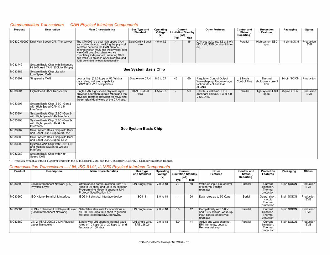
munication Transceivers — CAN Physical Interface Componentsoduct Description Main Characteristics Bus Type and
StandardOperating
Voltage(V)
CurrentLimitation Standby
(A) Typ Max
Other Features ConS
Rep
oducts available with SPI Control work with the KITUSBSPIEVME and the KITUSBSPIDGLEVME USB-SPI Interface Boards.
3CM0902 Dual High-Speed CAN Transceiver The CM0902 is a dual high-speed CAN transceiver device, providing the physical interface between the CAN protocol controller of an MCU and the physical dual wire CAN bus. Both channels are completely independent, featuring CAN bus wake-up on each CAN interface, and TXD dominant timeout functionality
Dual CAN HS dual wire
4.5 to 5.5 - 15 CAN bus wake-up, 3.3 or 5.0 V MCU I/O, TXD dominant time-out
P
3742 System Basis Chip with Enhanced High-Speed CAN (250k to 1Mbps) See System Basis Chip
3889 System Basis Chip Lite with Low-Speed CAN
3897 Single-wire CAN Low or high (33.3 kbps or 83.3) kbps data rates, wake-up capability (GMW3089 v2.3 compatible)
Single-wire CAN 6.0 to 27 45 60 Regulator Control OutputWaveshaping, Undervoltage lockout detect and loss of GND
2 Con
3901 High-Speed CAN Transceiver Single CAN high-speed physical layer provides operation up to 2 Mbps and the physical interface between an MCU and the physical dual wires of the CAN bus.
CAN HS dual wire
4.5 to 5.5 - 5.0 CAN bus wake-up. TXD dominant timeout, 3.3 or 5.0 V MCU I/O
P
3903 System Basis Chip (SBC)-Gen 2-with High Speed CAN & LIN Interfaces
See System Basis Chip
3904 System Basis Chip (SBC)-Gen 2-with High Speed CAN Interface
3905 System Basis Chip (SBC)-Gen 2-with High Speed CAN & LIN Interfaces
3907 Safe System Basis Chip with Buck and Boost DC/DC up to 800 mA
3908 Safe System Basis Chip with Buck and Boost DC/DC up to 1.5 A
3909 System Basis Chip with CAN, LIN and Multiple Switch-to-Ground Interface
3989 System Basis Chip with High-Speed CAN
roduct Description Main Characteristics Bus Type and Standard
Operating Voltage
(V)
CurrentLimitation Standby
(A) Typ Max
OtherFeatures
Co
Re
3399 Local Interconnect Network (LIN) Physical Layer
Offers speed communication from 1.0 kbps to 20 kbps, and up to 60 kbps for Programming Mode. It supports LIN Protocol Specification 1.3.
LIN Single-wire 7.0 to 18 20 50 Wake-up input pin, control of external voltage regulator
3660 ISO K Line Serial Link Interface ISO9141 physical interface device ISO9141 8.0 to 18 — 50 Data rates up to 50 Kbps
3661 eLIN – Enhanced LIN Physical Layer (Local Interconnect Network)
Selectable slew rate for operations at 10, 20, 100 kbps; bus short to ground fail-safe; excellent EMC behavior.
LIN Single-wire 7.0 to 18 8.0 12 Compatibility with 5.0 V and 3.3 V micros, wake-up input control of external regulator
3662 LIN 2.1/SAE J2602-2 LIN Physical Layer Transceiver
Single wire LIN supports normal baud rates of 10 kbps (J) or 20 kbps (L) and fast rate of 100 kbps
LIN single wire,SAE J2602-
7.0 to 18 6.0 11 Active bus waveshaping, EMI immunity, Local & Remote wakeup
Com
MC33 arallel Over-temperature protection, Output short-circuit
14-pin SOICN Production
MC33 SPI Current limitation
16-pin SOICN 2Q 2015EVB
Planned
MC33 arallel Overcurrent Outputs Short
to Battery, Overtemperat
ure Protect
32-pin SOICW ProductionEVB
Ref.Design
MC33
MC33
MC33
MC33
MC33
MC33
MC33
MC33
1. Pr
P us Sw. Resistance, typ/max ()
Packaging Status
MC33 n/a 16-pin SOICW
Production
MC33 n/an/a 32-pin SOICW
Exposed Pad
Production
MC33 3.0/6.0 16-pin SOICN
Production
MC33 n/a 64-pin LQFP
Exposed Pad
ProductionEVB
(contact sales)
MC33 6.0 16-pin SOICW
Production
MC33 4.0/8.0 16-pin SOICN Production
Pr trol and tatusorting1
ProtectionFeatures
Packaging Status
SG187 (Selector Guide) (1Q2015) – 11
munication Transceiver - Distributed Systems Interface (DSI) Components
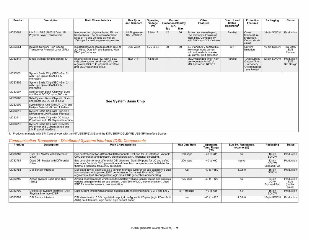
663 LIN 2.1 / SAEJ2602-2 Dual LIN Physical Layer Transceivers
Integrates two physical layer LIN bus transceivers. The devices offer baud rates of 10 and 20 kbps as well as 100 kbps for test/programming modes.
LIN Single-wire, SAE J2602-2
7.0 to 18 12 36 Active bus waveshaping, EMI immunity, 2 wake-up input pins, Compatibility with 5.0 V and 3.3 V micros
P
664 Isolated Network High Speed Transceiver Physical Layer (TPL)
Isolated network communication rate at 2.0 Mbps, Dual SPI architecture, High EMC performance
Dual wires 4.75 to 5.5 30 50 3.0 V and 5.0 V compatible, low sleep mode current with automatic bus wake up, current limit protection
812 Single cylinder Engine control IC Engine control power IC, with 3 Low-side drivers, one pre-driver, +5V pre-regulator, ISO-9141 physical interface and MCU watchdog circuit.
ISO-9141 4.5 to 36 — — MCU watchdog timer, +5V pre-regulator for MCU, MCU power on RESET
P
903 System Basis Chip (SBC)-Gen 2-with High Speed CAN & LIN Interfaces
See System Basis Chip
905 System Basis Chip (SBC)-Gen 2-with High Speed CAN & LIN Interfaces
907 Safe System Basis Chip with Buck and Boost DC/DC up to 800 mA
908 Safe System Basis Chip with Buck and Boost DC/DC up to 1.5 A
909 System Basis Chip with LIN, CAN and Multiple Switch-to-Ground Interface
910 System Basis Chip with High-side Drivers and LIN Physical Interface
911 System Basis Chip with DC Motor Pre-driver and LIN Physical Interface
912 System Basis Chip with DC Motor Pre-driver and Current Sense and LIN Physical Interface
oducts available with SPI Control work with the KITUSBSPIEVME and the KITUSBSPIDGLEVME USB-SPI Interface Boards.
roduct Description Main Characteristics Max Data Rate Operating Temp Range
(°C)
B
780 Dual DSI Master with Differential Drive
Bus controller for two differential DSI channels. SPI port for uC interface. Variable CRC generation and detection, thermal protection, frequency spreading.
150 kbps -40 to +85
781 Quad DSI Master with Differential Drive
Bus controller for four differential DSI channels. Dual SPI ports for uC and safing interfaces. Variable CRC generation and detection, comprehensive fault detection, thermal protection, frequency spreading
200 kbps -40 to +90
784 DSI Sensor Interface DSI slave device optimized as a sensor interface. Differential bus capability & dual bus switches for improved EMC performance, 2-channel 10-bit ADC, 5.0V regulated output, 3 configurable logic pins, CRC generation and checking.
n/a -40 to +150
789 Airbag System Basis Chip (IC) (SBC)
Air bag control module which monitors battery voltage, sensor status and supplies various voltages to the air bag system. Uses SPI for MCU communication. Uses PSI5 for satellite sensors communication.
125 kbps -40 to +125
790 Distributed System Interface (DSI) Physical Interface (DSIP)
Dual current-limited waveshaped outputs,current sensing inputs, 3.3 V and 5.0 V 5 - 150 kbps -40 to +85
793 DSI Sensor Interface DSI slave device. 5.0 V regulated output, 4 configurable I/O pins (logic I/O or 8-bit ADC), fault tolerant, logic output high current buffer.
n/a -40 to +125
oduct Description Main Characteristics Bus Type and Standard
Operating Voltage
(V)
CurrentLimitation Standby
(A) Typ Max
OtherFeatures
ConS
Rep

Millimet
Signal C
System
Produ Temp Range (°C)mbient Tempside of Die TempA TB
Packaging Status
MC33MR1 -40 to +125 Bare die 2Q 2015
MC33MR1 -40 to +125 Bare die 2Q 2015MC33MR2 -— 6x6 mm BGA Production
KITRADAR2001EVM
Produ OperatingVoltage (V)
Packaging Status
MC33811 10.5 to 15.5 16-pin SOICW ProductionEVB
MC33972 5.5 to 26 32-pin SOICW,32-pin SOICWExposed Pad
ProductionEVB
MC33975 5.5 to 26.5 32-pin SOICWExposed Pad
ProductionEVB
MC33978 4.5 to 36 32-pin SOICW Exposed Pad
Production EVB
Produ Protection Features Packaging Status
MC33742 ent and thermal protection for CAN and regulator
28-pin SOICW,48-pin QFN
ProductionEVB
MC33789 fing state machine, Scrap mode
64-pin LQFPExposed Pad
ProductionEVB
(contact sales)
MC33889 Fault tolerant 28-pin SOICW ProductionEVB
MC33903 ercurrent, Overtemperature, Short-circuit, protect
32-pin SOICWExposed Pad
ProductionEVB
SG187 (Selector Guide) (1Q2015) – 12
er Wave and Radar
onditioning
Basis Chip
ct Description Main Characteristics OperatingTA= A
TB= Back T
501 2-channel 77 GHz Radar Transmitter 3.3 V and 5.0 V power supply, Integrating fractional-N phase lock loop (PLL) with a voltage control oscillator (VCO), which can generate frequency modulation continuous waveform (FMCW) signals with digitally programmable frequencies
—
503 4-channel 77 GHz Radar Receiver 3.3 V power supply integrating mixer and IF buffer —001 Multi-channel 77 GHz Radar
Transceiver ChipsetScalable number of transmitter and receiver channels -40 to +125
ct Description Main Characteristics Switch Monitor
Voltage (V)Solenoid Monitor Integrated Circuit 5 input solenoid monitoring to verify proper electrical and mechanical solenoid operation. 0 to 64
22 input Multiple Switch Detect Interface with 16 mA Wetting Current and Suppressed Wake-up
Multiple switch detection interface with suppressed wake-up designed to detect closing and opening of up to 22 switch contacts (14 GND, 8 configurable), wetting current of 2.0 mA or 16 mA.
-14 to 38
-14 to 4022 input Multiple Switch Detect Interface with 32 mA Wetting Current and Wake-up
22 inputs contact monitoring (14 GND, 8 configurable), 4.0 mA or 32 mA pulse wetting current, low-power mode interrupt capability, wake-up. Can supply current to external sensors.
-14 to 38/40
22 input Multiple Switch Detect Interface with programmable Wetting Current
Multiple switch detection interface designed to detect closing and opening of up to 22 switch contacts (14 GND, 8 configurable), programmable wetting current from 2.0 to 20 mA. 24 to 1 Analog Multiplexer.
-14 to 38 V
ct Description Main Characteristics Bus Type and Standard
Operating
Voltage(V)
CurrentLimitation Standby
(A) Typ Ma
x
Other Features Control and
StatusReporting1
System Basis Chip with Enhanced High-Speed CAN (250K to 1Mbps)
SBC, Dual VREG, Enhance HS CAN with Bus failure diagnostic capability, 4 wake-up inputs.
CAN High-Speed dual wires
5.5 to 27 60 150 Low power modes, remote and local wake-up capabilities
SPI Curr
Airbag System Basis Chip (SBC) with Power Supply and PSI5 Sensor Interface
Air bag control module which monitors battery voltage, sensor status and supplies various voltages to the air bag system. Uses SPI for MCU communication. Uses PSI5 for satellite sensors communication.
PSI5 5.2 to 20 - - Safing state machine, 9 switch input monitors, 2 config. high/low side drivers, Power-on-reset, watchdog timer, Squib energy reserve
SPI Sa
System Basis Chip with Low-Speed Fault Tolerant CAN
Dual 5.0 V regulators LS CAN, 2 wake-up inputs
CAN Low-Speed,dual wires
5.5 to 27 60 100 Dual voltage regulator, Watchdog, wake-up input, sleep and stop modes
SPI
System Basis Chip (SBC)-Gen 2-with High Speed CAN & LIN Interfaces
High speed CAN and 1 or 2 LIN physical interface. 5.0 or 3.3 V VDD regulator.
CAN high-speed, dual wires,
LIN single wire
5.5 to 27 15 35 Fail-safe state machine, Configurable I/O, MUX - out, pin compatible with MC33905
“Secured” SPI
Ov
MC33 ercurrent, Overtemperature, ort -circuit and undervoltage
detect
32-pin SOICWExposed Pad
ProductionEVB(‘905)
MC33 ercurrent, Overtemperature, ort -circuit and undervoltage
detect
32-pin SOICWExposed Pad,54-pin SOICWExposed Pad
ProductionEVB
MC33 ercurrent, Overtemperature, ver & Undervoltage detect
48-pin LQFPExposed Pad
ProductionEVB
MC33 ercurrent, Overtemperature, ver & Undervoltage detect
48-pin LQFPExposed Pad
ProductionEVB
MC33 Overvoltage 64-pin LQFP Exposed Pad
4Q 2015EVB
Planned
MC33 ltiple wake-up sources, LDO Fault Detect,
Low Voltage Reset
32-pin LQFP ProductionEVB (‘912)
MC33 ltiple wake-up sources, LDO Fault Detect,
Low Voltage Reset
32-pin LQFP ProductionEVB (‘912)
MC33 ltiple wake-up sources, LDO Fault Detect,
Low Voltage Reset
32-pin LQFP ProductionEVB
MC33 Current limitation, thermal 28-pin SOICW ProductionEVB
1. Pr
P Protection Features Packaging Status
SG187 (Selector Guide) (1Q2015) – 13
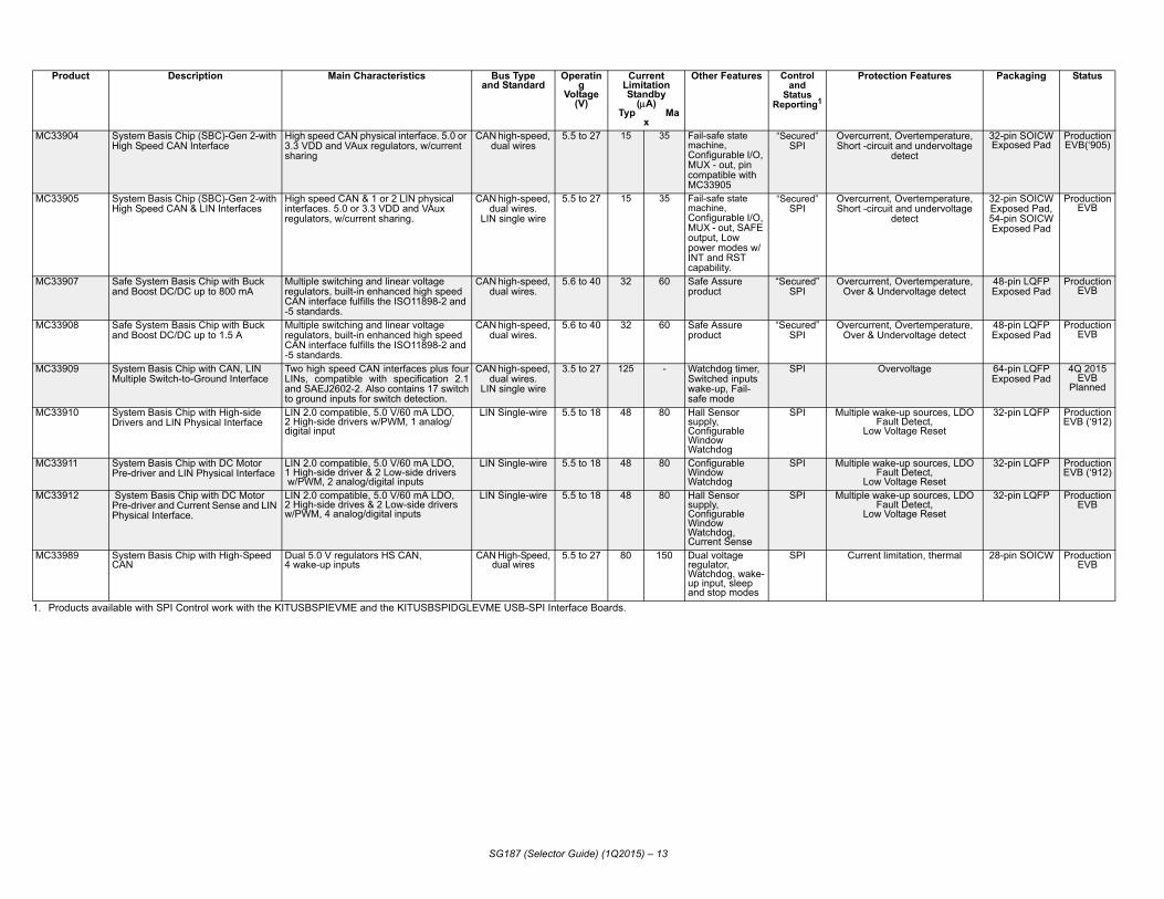
904 System Basis Chip (SBC)-Gen 2-with High Speed CAN Interface
High speed CAN physical interface. 5.0 or 3.3 VDD and VAux regulators, w/current sharing
CAN high-speed, dual wires
5.5 to 27 15 35 Fail-safe state machine, Configurable I/O, MUX - out, pin compatible with MC33905
“Secured” SPI
OvSh
905 System Basis Chip (SBC)-Gen 2-with High Speed CAN & LIN Interfaces
High speed CAN & 1 or 2 LIN physical interfaces. 5.0 or 3.3 VDD and VAux regulators, w/current sharing.
CAN high-speed, dual wires.
LIN single wire
5.5 to 27 15 35 Fail-safe state machine, Configurable I/O, MUX - out, SAFE output, Low power modes w/INT and RST capability.
“Secured” SPI
OvSh
907 Safe System Basis Chip with Buck and Boost DC/DC up to 800 mA
Multiple switching and linear voltage regulators, built-in enhanced high speed CAN interface fulfills the ISO11898-2 and -5 standards.
CAN high-speed, dual wires.
5.6 to 40 32 60 Safe Assure product
“Secured” SPI
OvO
908 Safe System Basis Chip with Buck and Boost DC/DC up to 1.5 A
Multiple switching and linear voltage regulators, built-in enhanced high speed CAN interface fulfills the ISO11898-2 and -5 standards.
CAN high-speed, dual wires.
5.6 to 40 32 60 Safe Assure product
“Secured” SPI
OvO
909 System Basis Chip with CAN, LIN Multiple Switch-to-Ground Interface
Two high speed CAN interfaces plus four LINs, compatible with specification 2.1 and SAEJ2602-2. Also contains 17 switch to ground inputs for switch detection.
CAN high-speed, dual wires.
LIN single wire
3.5 to 27 125 - Watchdog timer, Switched inputs wake-up, Fail-safe mode
SPI
910 System Basis Chip with High-side Drivers and LIN Physical Interface
LIN 2.0 compatible, 5.0 V/60 mA LDO, 2 High-side drivers w/PWM, 1 analog/digital input
LIN Single-wire 5.5 to 18 48 80 Hall Sensor supply,Configurable Window Watchdog
SPI Mu
911 System Basis Chip with DC Motor Pre-driver and LIN Physical Interface
LIN 2.0 compatible, 5.0 V/60 mA LDO, 1 High-side driver & 2 Low-side drivers w/PWM, 2 analog/digital inputs
LIN Single-wire 5.5 to 18 48 80 Configurable Window Watchdog
SPI Mu
912 System Basis Chip with DC Motor Pre-driver and Current Sense and LIN Physical Interface.
LIN 2.0 compatible, 5.0 V/60 mA LDO, 2 High-side drives & 2 Low-side drivers w/PWM, 4 analog/digital inputs
LIN Single-wire 5.5 to 18 48 80 Hall Sensor supply, Configurable Window Watchdog, Current Sense
SPI Mu
989 System Basis Chip with High-Speed CAN
Dual 5.0 V regulators HS CAN, 4 wake-up inputs
CAN High-Speed, dual wires
5.5 to 27 80 150 Dual voltage regulator, Watchdog, wake-up input, sleep and stop modes
SPI
oducts available with SPI Control work with the KITUSBSPIEVME and the KITUSBSPIDGLEVME USB-SPI Interface Boards.
roduct Description Main Characteristics Bus Type and Standard
Operating
Voltage(V)
CurrentLimitation Standby
(A) Typ Ma
x
Other Features Control and
StatusReporting1

BatPr Protection
FeaturesPackaging Status
MC33 ept: over/undervoltage, over/erature, open/ short cell etection. Failure can be the fault pin output
64-pin LQFP-EP
2Q 2015EVB
EmPr ditional Information Packaging Status
MM9 Internal or external temp O, including SPI functionality, xternal oscillator. Window ith Selectable Timing,
p/Sleep/Crank Mode Ctrl. e Wake-up Inputs,
48-pin QFN,Exposed Pad
ProductionEVB
MM9 voltage measurements with istor dividers, and up to five e measurements for use with resistor divider. Measurement tion between voltage d current channels.
48-pin QFNExposed Pad
ProductionEVB
Ref. Design
MM9 tions consists of three ow side drivers, one pre-.0 V, voltage pre-regulator, an dog circuit, an ISO 9141 K-ce, and a parallel interface for unication. The three low side provided for driving a fuel mp or LED, and a relay, ctor or fuel pump.
100 lead LQFP,Exposed Pad
ProductionRef.Design
MM9 tions consists of three ow side drivers, one pre-.0 V, voltage pre-regulator, an dog circuit, an ISO 9141 K-ce, and a parallel interface for unication. The three low side provided for driving a fuel mp or LED, and a relay, ctor or fuel pump.
100 lead LQFP,Exposed Pad
ProductionRef. Design
S12Pr Additional Information Packaging Status
MM9 gh Voltage Wake-up Inputs, lectable Gain I-Sense, ttery Voltage Sense. Timing, rmal/Stop/Sleep Mode ntrol, Hall Supply of 18 V/30
48-pin LQFPExposed Pad
ProductionEVB
SG187 (Selector Guide) (1Q2015) – 14
tery Management - Battery Cell Controlleroduct Description Main Characteristics Operating
Voltage (V)Output Voltages
771 Battery Cell Controller IC (BCC) 4 Mbps SPI Interface or Isolated 2Mbps Differential Communication14 Cells Terminal, 1 current channel with Auto PGA 7 Configurable ADC/GPIO/Temperature Sensor Inputs5.0 V @ 5 mA Temp Reference Supply OutputI2C EEPROM interfaceFault OutputFailure detection: OV/UV voltage, OV/UV temp, internal diagnostics
9.6 to 61.6 Cell balancing : 10 V to 12 VFault pin: 5.0 V
GPIO: 5.0 V or 3.3 V
Safety concunder tempbalancing dreported by
bedded MCU plus Power - S12 Mixed-Signal Analog MCUsoduct Description Main Characteristics MCU References MCU Details Ad12_637 Battery Sensor with LIN for 12 V
Lead-acid Batteries Simultaneous Battery voltage & current measurement with 16-bit sigma-delta ADC & IIR filter. Voltage Regulators: 2.5 V/10mA & 60mA, 5.0 V/80 mA. LIN 2.1 Physical Layer w/Selectable Slew rates and triggered wake-up,
16-bit MCUCPU12_V1
S12 16-bit core, 128 K/96 KBytes Flash, 6 KBytes RAM, 4 K Bytes data Flash, ESCI, 16-bit 4 Channel Timer, Internal Clock Generator, BDM
Selectable sense, GPIinternal or eWatchdog wNormal/StoHigh Voltag
Z1_638 Battery Sensor with CAN and LIN This is a fully integrated battery monitoring device. The device supports precise current measurement via an external shunt resistor. The MM9Z1_638 includes LIN 2.2 protocol and physical interface, and an MSCAN protocol controller,
16-bit MCUS12Z
S12Z MCU with 128 KB Flash, 8 KB RAM, 4 KB EEPROM
Four batteryinternal resdirect voltagan external synchronizachannels an
12_P812 S12P MCU and Multifunctional Ignition and Injector Driver System In Package (SiP)
An engine control IC combining an MCU (S12P) and analog control die (MC33812) intended for motorcycle and other single/dual cylinder small engine control applications.
16-bit MCU S12P
The MCU S12P has 6 KB RAM, and flash memory size of 96 KB or 128 KB. The S12P family uses many of the same features found on the S12XS family, including error correction code (ECC) on flash memory, a separate data-flash module for diagnostic or data storage, a fast analog-to-digital converter (ATD), and a frequency modulated phase locked loop (IPLL) that improves electromagnetic compatibility (EMC).
Analog funcintegrated ldriver, a +5MCU watchLine interfaMCU commdrivers are injector, a laanother inje
12_S812 S12XS MCU and Multifunctional Ignition and Injector Driver System In Package (SiP)
An engine control IC combining an MCU (S12XS) and analog control die (MC33812) intended for motorcycle and other single/dual cylinder small engine control applications.
16-bit MCU S12XS
The MCU S12XS has 8 KB or 12 KB RAM, and flash memory size of 128 KB or 256 KB. The S12XS family uses many of the same features found on the S12P family, including error correction code (ECC) on flash memory, a separate data-flash module for diagnostic or data storage, a fast analog-to-digital converter (ATD), and a frequency modulated phase locked loop (IPLL) that improves the electromagnetic compatibility (EMC) performance.
Analog funcintegrated ldriver, a +5MCU watchLine interfaMCU commdrivers are injector, a laanother inje
Mixed-Signal Analog MCUsoduct Description Main Characteristics Power Features MCU Reference MCU Detail12_634 Integrated S12 MagniV Based Relay
Drivers with LIN Cascaded dual Voltage Regulator 2.5 V/50 mA and 5.0 V/80 mA, LIN Physical Layer with Selectable Slew rates, Window Watchdog with Selectable Dual High-side and Dual Low Side Switches with Embedded S12 MCU + Power + LIN
7 High-side Switches,2.5 Low-side Switches for
relay drivel
16-bit MCU S12 16-bit Core, 32KB Flash, 2KB RAM, ESCI, Multi channel 10-bit ADC, 16-bit 4 Channel Timer, Internal Clock Generator
HiSeBaNoComA

8-biPr Additional Information Packaging Status
MM9 Pin Hall Sensor Input, alog Input with Current urce, 40 V Rated Wake-up ut, Vsup, Chip Temp. and rrent Sensing
54-pin SOICWExposed Pad
Production
MM9 Pin Hall Sensor Input, alog Input withrrent Source, 40 V Rated ke-up Input, Vsup, Chip
mp. and Current Sensing
54-pin SOICWExposed Pad
Production
MM9 erational Amplifier, 2 x 40 V ted Wake-up Inputs
54-pin SOICW ProductionEVB
MM9 2 Pin Hall Sensor Inputs with clic Wake-up Feature, Analog ut with Current Source, Vsup, ip Temp. and Current Sensing
54-pin SOICWExposed Pad
ProductionEVB
MM9 up, Chip Temperature and rrent Sensing
54-pin SOICWExposed Pad
ProductionEVB (‘625)
SG187 (Selector Guide) (1Q2015) – 15
t Intelligent Distributed Controllersoduct Description Main Characteristics Power Features MCU Reference MCU Detail08E621 DC Motor/Mirror Control and LIN
Mirror Control, Integrated Quad Half-Bridge and Triple High-side with Embedded MCU and LIN
Voltage Regulator 5.0 V/60 mA, LIN Physical Layer with Selectable Slew rates, Window Watchdog, “Normal/Stop/Sleep Mode “Control
2 x 275 m Half-Bridges;2 x 750 m Half-Bridges;
1 x 185 m High-side;2 x 440 m High-side;
Switched 5.0 V Output (25 mA)
8-bit MCU HC908EY16
HC08 Core, 16K Flash, 512 Bytes RAM, ESCI,8-Channel 10-bit ADC, Two 16-bit 2 Channel Timers, Internal Clock Generator
2/3AnSoInpCu
08E622 DC Motor/Mirror Control and LIN Mirror Control, Integrated Quad Half-Bridge, Triple High-side and EC Glass Driver with Embedded MCU and LIN
Voltage Regulator 5.0 V/60 mA, LIN Physical Layer with Selectable Slew rates, Window Watchdog, “Normal/Stop/Sleep Mode “Control
2 x 275 m Half-Bridges;2 x 750 m Half-Bridges;
1 x 185 m High-side;2 x 440 m High-side;
Switched 5.0 V Output (25 mA)EC Glass Driver
2/3AnCuWaTe
08E624 DC Motor Control Using Relays (for example, Window Lift, Sun Roof, and Power Seats), Triple High-side Switch with Embedded MCU + Power + LIN
Voltage Regulator 5.0 V/50 mA, LIN Physical Layer with Selectable Slew rates, Window Watchdog with Selectable Timing, Normal/Stop/Sleep Mode Control
1 x 7 High-side,2 x 2.5 High-side Switches for
Relay Control
OpRa
08E625 Mirror Control, Stepper Motor Control, Door Lock Quad Half-Bridge and Single High-side with Embedded MCU and LIN
Voltage Regulator 5.0 V/60 mA, LIN Physical Layer with Selectable Slew rates, Timeout Watchdog with Periodic Wake-up Feature, Normal/Stop Modes
4 x 400 m Half-Bridges withCurrent Control;
1 x 600 m High-side; Switched 5.0 V Output (25 mA)
3 xCyInpCh
08E626 Stepper Motor Control, Quad Half-Bridge with Embedded MCU and LIN
Voltage Regulator 5.0 V/60 mA, LIN Physical Layer with Selectable Slew rates. High Temperature use, TJ = 135×C
4 x 400 m Half-Bridges withCurrent Control;
Switched 5.0 V Output (24 mA)
VsCu

FRE
Power MProdu tics1
1. Produc
Protection Features Packaging Status
MC3373 Reverse Battery Protect, Undervoltage and Overvoltage Lockout, Reset monitor signals for regulators (4)
32-pin SOICW ProductionEVB
MC33742
MC33889
MC33903
MC33904
MC33905
MC33907
MC33908
MC33909
MC33989
The PovoltageapplicaSMARTinterfac
SG187 (Selector Guide) (1Q2015) – 16
ESCALE SEMICONDUCTOR POWER MANAGEMENT PRODUCTS
anagement — Linear Regulators ct Description Main Characteristics Bus Type and
StandardOperating
Voltage (V)
CurrentLimitation Standby
(A) Typ Max
Other Features Diagnos
ts available with SPI Control work with the KITUSBSPIEVME and the KITUSBSPIDGLEVME USB-SPI Interface Boards.
Switch Mode Power Supply with Multiple Linear Regulators and Power Sequencing
Step-down Switching regulator (2.0 A), with 3 Programmable Linear Regulators (15 mA, 15 mA, 15 mA) and two 5.0 V Sensor supplies (100 mA, 100 mA).
n/a 4.5 to 28 150 — Programmable voltage regulator, power sequencing, adjustable OSC - Switcher
None
System Basis Chip with enhanced High-Speed CAN (250k to 1Mbps)
See System Basis Chip
System Basis Chip with Low-Speed Fault Tolerant CANSystem Basis Chip (SBC)-Gen 2-with High Speed CAN & LIN InterfacesSystem Basis Chip (SBC)-Gen 2-with High Speed CAN InterfacesSystem Basis Chip (SBC)-Gen 2-with High Speed CAN & LIN InterfacesSystem Basis Chip (SBC) with CAN, LIN, and SPI InterfacesSystem Basis Chip (SBC) with CAN, LIN, and SPI InterfacesSystem Basis Chip (SBC) with CAN and LIN InterfacesSystem Basis Chip with High-Speed CAN
wer Management products portfolio provides solutions for Linear and Switching regulators. Hot Swap control and Power over Ethernet devices for use in tions ranging from Consumer and Industrial to Automotive.MOS — Freescale Semiconductor SMARTMOS technology allows designers to e high-precision components with the harsh automotive environment.
For additional information, visit:Documentation, Tool, and Product Libraries www.freescale.comwww.freescale.com/analogwww.freescale.com/powermanagementwww.freescale.com/productlongevity

Auto
PowPr Protection Features Packaging Status
MC33 erse Battery Protect, ervoltage and Overvoltage kout, Reset monitor signals for ulators (4)
32-pin SOICW ProductionEVB
Pr cs Protection Features Packaging Status
TC80 cation trical, and porting
Load Dump Protection, Thermal protection,
Thermal compensation
Die Production
Note:
SG187 (Selector Guide) (1Q2015) – 17
motive Alternator Voltage Regulators
er Management — Switching Regulatorsoduct Description Main Characteristics Operating Voltage (V) Output Voltages730 Switch Mode Power Supply
with Multiple Linear Regulators and Power Sequencing
Step-down Switching regulator (2.0 A), with 3 Programmable Linear Regulators (15 mA, 15 mA, 15 mA) and 2 x 5.0 V sensor supply (100 mA, 100 mA)
4.5 to 28 4.9 to 5.1 V,2.0 to 3.3 V,1.5 to 3.3 V,1.0 to 5.0 V,
5.0 V
RevUndLocreg
oduct Description Main Characteristics Bus Type OperatingVoltage
Regulation Voltage
Other Features Diagnosti
310 An integrated circuit intended to regulate the output voltage of an automotive alternator. It supplies a current via a high-side MOSFET to the excitation coil of the alternator and provides an internal free-wheeling diode.
High-side field driver, Internal freewheeling diode, Up to 8.0 A rotor current (excitation coil), Load response control (LRC), LIN interface, Set point voltage selectable
LIN 1.3 8 to 27 150 Factory Selectable Features: LRC Rate, LRC disable RPM, Self start, Self start threshold, Alternator Pole pairs, Thermal Fault Threshold, Thermal Compensation Threshold, Phase Sensitivity, Phase Start Regulating RPM, Phase Stop Regulating RPM
LIN communiused for Elec
MechanicalThermal fault re
Choice of 16 parametric fields may be specified by the customer. Contact sales for specific parameter combinations and part numbering.

FREE
Pressur
Barome
FreesMonitmana(MAPOur Zfunctifrom e
motive sensors are designed for a variety mance to comfort and control. Our sensors ns, and are compatible with Freescale
ocontroller families..com/automotive
Pro Status
MPX4115A e (SSOP) AvailableAvailable
MPX4250 AvailableAvailable
MPXV500 AvailableMPXV501 AvailableMPX5100 e AvailableMPX5700 e AvailableMPX5999 e AvailableMPXH610 AvailableMPXV700 AvailableMPXV702 Available
Pro Status
MPXH610 e (SSOP) AvailableMPXA611 AvailableMPXAZ61 AvailableMPXHZ61 AvailableMPXH625 AvailableMPXHZ62 AvailableMPXH630 AvailableMPXH640 AvailableMPXHZ64 Available
SG187 (Selector Guide) (1Q2015) – 18
SCALE SEMICONDUCTOR AUTOMOTIVE SENSORS
e Sensors
tric Absolute Pressure (BAP) and Manifold Absolute Pressure (MAP) Sensors
cale is a leading sensor supplier for automotive safety for airbags, Tire Pressure oring Systems (TPMS), Electronic Stability Control (ESC) and for engine gement with barometric absolute pressure (BAP) and manifold absolute pressure ) applications.. ero Defects process, Automotive Electronics Council (AEC) membership and onal safety with Safe Assure are critical in providing world-class quality solutions ntry-level to the high end.
Applications — Freescale Semiconductor autoof applications ranging from safety and perforare used in under-hood and in-cabin applicatioanalog product, power management and micrFor additional information, visit www.freescale
duct MaximumPressure Rating (kPa)
Full Scale Span Voltage(Typical) (Vdc)
Sensitivity(mV/kPa)
Accuracy 0 C to 85 C(% of VFSS)
Packaging
115115
4.64.4
4638
±1.5±1.5
Super-Small Outline PackagSSOP
A 250250
4.74.7
2019
±1.5±1.4
SSOPSSOP
4 4 3.9 1000 ±2.5 SOP0 10 4.5 450 ±5.0 SOP
100 4.5 45 ±2.5 6-pin unibody packag700 4.5 6.4 ±2.5 6-pin unibody packag
1000 4.5 4.5 ±2.5 6-pin unibody packag1 102 4.6 54 ±1.8 SSOP7 7 4.0 286 ±5.0 SOP5 25 4.5 90 ±5.0 SOP
duct MaximumPressure Rating (kPa)
Full Scale Span Voltage(Typical) (Vdc)
Sensitivity(mV/kPa)
Accuracy 0 C to 85 C(% of VFSS)
Packaging
1 102 4.6 54 ±1.8 Super-Small Outline Packag5 115 4.6 45.9 ±1.5 SOP15A 115 4.5 45.9 ±1.5 SOP15A 115 4.5 45.9 ±1.5 SSOP0A 250 4.7 20 ±1.5 SSOP50 250 4.7 20 ±1.5 SSOP0 300 4.7 16 ±1.8 SSOP0 400 4.7 12 ±1.5 SSOP00 400 4.7 12 ±1.5 SSOP

Inerommunication Packaging Status
AnaMMA — 16-pin SOIC Available
MMA — 16-pin SOIC Available
MMA — 16-pin SOIC Available
MMA — 16-pin SOIC Available
MMA — 16-pin SOIC Available
MMA — 16-pin SOIC Available
MMA — 16-pin SOIC Available
MMA — 16-pin SOIC Available
MMA — 16-pin SOIC Available
MMA — 16-pin SOIC Available
MMA — 20-pin SOIC Available
MMA — 20-pin SOIC Available
MMA — 20-pin SOIC Available
MMA — 20-pin SOIC Available
DigiMMA PSI5 16-pin QFN Available
MMA PSI5 16-pin QFN Available
MMA PSI5 16-pin QFN Available
MMA PSI5 16-pin QFN Available
MMA PSI5 16-pin QFN Available
MMA PSI5 16-pin QFN Available
MMA PSI5 16-pin QFN Available
MMA PSI5 16-pin QFN Available
MMA DSI 16-pin QFN Available
MMA DSI 16-pin QFN Available
MMA DSI3 QFN 6x6 mm 16-pin Available
MMA DSI3 Self Test Available
MMA DSI3 Self Test Available
MMA DSI3 Self Test Available
MMA DSI3 Self Test Available
MMA DSI3 Self Test Available
1. Fre D = 5.0 V and T = 25 C, unless otherwise specified. Ad
SG187 (Selector Guide) (1Q2015) – 19
tial Sensors1 Product Sensing
DirectionAcceleration (±g) Sensitivity
(mV/V/g)Sensitivity(count/g)
TemperatureRange
Roll-Off Frequency
Analog Digital C
log Sensors:1270KEG Z 2.5 g 150 — -40 C to +105 C 50 Hz Yes —
1250KEG Z 5 g 80 — -40 C to +105 C 50 Hz Yes —
1220KEG Z 8 g 50 — -40 C to +85 C 250 Hz Yes —
2240KEG X 7 g 300 — -40 C to +125 C 50 Hz Yes —
2244KEG X 20 g 100 — -40 C to +125 C 400 Hz Yes —
2201KEG X 40 g 10 — -40C to +125 C 400 Hz Yes —
2202KEG X 50 g 8 — -40 C to +125 C 400 Hz Yes —
2204KEG X 100 g 4 — -40 C to +125 C 400 Hz Yes —
2300KEG X 250 g 1.6 — -40 C to +125 C 400 Hz Yes —
2301KEG X 200 g 2 — -40 C to +125 C 400 Hz Yes —
3201KEG XY 40 g 10 — -40 C to +125 C 400 Hz Yes —
3221KEG XY 50/20 g 40/100 — -40 C to +125 C 400 Hz Yes —
3204KEG XY 100/30 g 4/13 — -40 C to +125 C 400 Hz Yes —
3202KEG XY 100/50 g 4/8 — -40 C to +125 C 400 Hz Yes —
tal Sensors:5106KW Z 60 g — 8 -40 C to +125 C 400 Hz — Yes
5112KW Z 120 g — 4 -40 C to +125 C 400 Hz — Yes
5124KW Z 240 g — 2 -40 C to +125 C 400 Hz — Yes
5148KW Z 480 g — 1 -40 C to +125 C 400 Hz — Yes
5206KW X 60 g — 8 -40 C to +125 C 400 Hz — Yes
5212KW X 120 g — 4 -40 C to +125 C 400 Hz — Yes
5224KW X 240 g — 2 -40 C to +125 C 400 Hz — Yes
5248KW X 480 g — 1 -40 C to +125 C 400 Hz — Yes
2612KW X 125 g — 4.096 -40 C to +125 C 400 Hz — Yes
1618KW Z 187 g — 2.731 -40 C to +125 C 400 Hz — Yes
2725W X 250 g — 2 -40 C to +125 C 400 Hz — Yes
2712W X 125 g — 4 -40 C to +125 C 400 Hz — Yes
2737W X 375 g — 1.3 -40 C to +125 C 400 Hz — Yes
2718W X 187 g — 2.7 -40 C to +125 C 400 Hz — Yes
2702W X 25 g — 20.4 -40 C to +125 C 400 Hz — Yes
1725W Z 250 g — 2 -40 C to +125 C 400 Hz — Yes
escale Semiconductor reserves the right to modify product specifications and/or introduction dates without any further notice. The product parameters are typical values at VDditional sensitivity and expanded temperature ranges are available upon request. Consult your Freescale Semiconductor sales representative

MMA6255 SPI 16-pin QFN Available
MMA6852 SPI 16-pin QFN Available
MMA6854 SPI 16-pin QFN Available
MMA6811 SPI 16-pin QFN Available
MMA6813 SPI 16-pin QFN Available
MMA6821 SPI 16-pin QFN Available
MMA6823 SPI 16-pin QFN Available
MMA6826 SPI 16-pin QFN Available
MMA6852 SPI 16-pin QFN Available
MMA6900 SPI 16-pin QFN Available
MMA6901 SPI 16-pin QFN Available
1. Freesca = 5.0 V and T = 25 C, unless otherwise specified. Additio
Tire PreProd ture
eStatus Description
FXTH8705 5 °C ContactFreescale
Automotive Pressure Range(with Z Axis Accelerometer)
FXTH8705 5 °C ContactFreescale
Automotive Pressure Range(with XZ Axis Accelerometer)
FXTH8709 5 °C ContactFreescale
Automotive Pressure Range(with Z Axis Accelerometer)
FXTH8709 5 °C ContactFreescale
Automotive Pressure Range(with XZ Axis Accelerometer)
FXTH8709 5°C ContactFreescale
Automotive Pressure Range(with XZ Axis Accelerometer)
FXTH8709 5 °C ContactFreescale
Automotive Pressure Range(with XZ Axis Accelerometer)
InertialP munication Packaging Status
SG187 (Selector Guide) (1Q2015) – 20
KEG XY 50/50 g — 9.76 -40C to +125 C 400 Hz — Yes
KW X 35 g — 13.947 -40C to +105 C 400 Hz — Yes
KW X 75 g — 6.51 -40C to +105 C 400 Hz — Yes
KW XY 60/25 g — 8.192/20.479 -40C to +105 C 400 Hz — Yes
KW XY 50/50 g — 9.766/9.766 -40C to +105 C 400 Hz — Yes
KW XY 120/25 g — 4.096/20.479 -40C to +105 C 400 Hz — Yes
KW XY 120/60 g — 4.096/8.192 -40C to +105 C 400 Hz — Yes
KW XY 60/60 g — 8.192/8.192 -40C to +105 C 400 Hz — Yes
KW XY 120/120 g — 4.096/4.096 -40C to +105 C 400 Hz — Yes
KQ XY 3.5 g — 291.5 -40C to +105 C 50 Hz — Yes
KQ XY 5g — 203.6 -40C to +105 C 50 Hz — Yes
le Semiconductor reserves the right to modify product specifications and/or introduction dates without any further notice. The product parameters are typical values at VDDnal sensitivity and expanded temperature ranges are available upon request. Consult your Freescale Semiconductor sales representative.
ssure Monitoring Systemsuct Flash RAM RF Transmitter
FrequencyProtocols Supported
ClockType
Timer Pressure Range Pressure Sensor Accuracy
Package TemperaRang
02DT1 16 KB 512 B 315/434MHz ASK and FSK Modulation OSC 2-CH, 16-bit PWM 100 - 450 kPA ±15 kPA 7x7 QFN FAM -40 to 12
11DT1 16 KB 512 B 315/434MHz ASK and FSK Modulation OSC 2-CH, 16-bit PWM 100 - 450 kPA ±15kPA 7x7 QFN FAM -40 to 12
02DT1 16 KB 512 B 315/434MHz ASK and FSK Modulation OSC 2-CH, 16-bit PWM 100 - 900 kPA ±15 kPA 7x7 QFN FAM -40 to 12
11DT1 16 KB 512 B 315/434MHz ASK and FSK Modulation OSC 2-CH, 16-bit PWM 100 - 900 kPA ±15 kPA 7x7 QFN FAM -40 to 12
12DT1 16 KB 512 B 315/434MHz ASK and FSK Modulation OSC 2-CH, 16-bit PWM 100 - 900 kPA ±15kPA 7x7 QFN FAM -40 to 12
226T1 16 KB 512 B 315/434MHz ASK and FSK Modulation OSC 2-CH, 16-bit PWM 100 - 900 kPA ±15 kPA 7x7 QFN FAM -40 to 12
Sensors1 (continued)roduct Sensing
DirectionAcceleration (±g) Sensitivity
(mV/V/g)Sensitivity(count/g)
TemperatureRange
Roll-Off Frequency
Analog Digital Com

FR
GPSSystem
ApplicabilityDocumentation
MRFI GPS MRFIC1505
FoDoww
SG187 (Selector Guide) (1Q2015) – 21
EESCALE SEMICONDUCTOR ACCESS AND REMOTE CONTROL PRODUCTS
DownconverterProduct RF Freq (MHz) Supply Voltage
Range (Vdc)Supply Current (Typ)
(mA)Standby Current
(mA)Conversion Gain
(typ) (dB)Packaging
C1505A 1575.42 2.7 to 3.3 28 3 105 48-pin LQFP(Case No 932)
r additional information, visit:cumentation, Tool, and Product Libraries w.freescale.com
Automotive Home Pagewww.freescale.com/automotive
FREE S
LIN SofS12X
LIN maste AvailableLIN slave AvailableOperating Available
LIN PhyProduct ther
turesControl and
StatusReporting
Packaging Status
MC33399MC33661MC33662
FreesconsocompCost Bself-sycost bonly toEmbehardwbroadparts
lers will evolve in the LIN environment to face, and high-voltage I/O to provide space, onductor solutions provide this capability
is working closely with the leading LIN tool elopment and debug environment for
e
SG187 (Selector Guide) (1Q2015) – 22
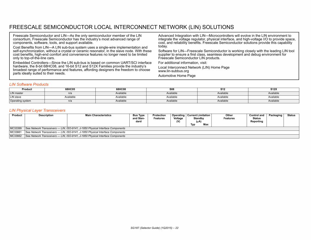
SCALE SEMICONDUCTOR LOCAL INTERCONNECT NETWORK (LIN) SOLUTION
tware ProductsProduct 68HC05 68HC08 S08 S12r n/a Available Available Available
Available Available Available Available system n/a Available Available Available
sical Layer TransceiversDescription Main Characteristics Bus Type
and Stan-dard
ProtectionFeatures
OperatingVoltage
(V)
Current Limitation Standby
(A) Typ Max
OFea
See Network Transceivers — LIN, ISO-9141, J-1850 Physical Interface Components See Network Transceivers — LIN, ISO-9141, J-1850 Physical Interface Components See Network Transceivers — LIN, ISO-9141, J-1850 Physical Interface Components
cale Semiconductor and LIN—As the only semiconductor member of the LIN rtium, Freescale Semiconductor has the industry’s most advanced range of onents, software, tools, and support available.
enefits from LIN—A LIN sub-bus system uses a single-wire implementation and nchronization, without a crystal or ceramic resonator, in the slave node. With these enefits, high-end comfort and convenience features no longer need to be limited top-of-the-line cars.
dded Controllers—Since the LIN sub-bus is based on common UART/SCI interface are, the 8-bit 68HC08, and 16-bit S12 and S12X Families provide the industry’s est range of performance and features, affording designers the freedom to choose ideally suited to their needs.
Advanced Integration with LIN—Microcontrolintegrate the voltage regulator, physical intercost, and reliability benefits. Freescale Semictoday.Software for LIN—Freescale Semiconductor supplier to ensure a first class, seamless devFreescale Semiconductor LIN products.For additional information, visit:Local Interconnect Network (LIN) Home Pagwww.lin-subbus.orgAutomotive Home Page

MApTra C5777M, S12XE, S12P, S12GHyb 5746G, MPC5747C, MPC5747G, MPC5748C, MPC55748G,
WaHigBod PC5748C, MPC5748G, S12G, S12XE, KEA
HV 8SG, S08SL, S08MP16, S08SC4, S08RN, KEA
BodInfoTelIns 2ZVH, S12ZVY S08LG, MAC57D5xx HeMuBraEleTireSemAirbEleLanAdvPreEth C5746M, MPC577xK, all i.MX Fle 5642A, MPC5744P, MPC5748G, MPC5747C, MPC5747G,
CA C5748C, MPC5748G, MPC5746M, MPC577xK all S12(X), S08D,
LIN P, S12XS, S12XE, S12G, S12X, S12VR64, S08SG, S08EL, S08AW,
SG187 (Selector Guide) (1Q2015) – 23
CU CHOICES BY APPLICATIONplication Microcontroller
nsmission, Engine Control and Management Interfaces MPC5674F, MPC5673F, MPC563xM, MPC5644A, MPC5643A, MPC5642A, MPC5746M, MPrid and Electric Auxiliaries MPC5674F, MPC5673F, MPC563xM, MPC5644A, MPC5643A, MPC5642A, MPC5744P, MPC
MPC5746M, S12Gtchdog S12G, S12P, S08QD4, S08SG, S08AW, S08SC4, S08RN h Temperature MPC5744P, S12G, S08SGy Control Module and Gateway MPC5668x, MPC560xB, MPC560xD, MPC564xB/C, MPC5746G, MPC5747C, MPC5747G, M
AC, Lighting, Seats, Window Lift, Doors, Sun Roof MPC560xB, MPC560xD, S12XS, S12P, S12G, S12VR, S12ZVFP, S08D, S08AW, S08EL, S0
y Motor Control S12G, S12VR, S08MP16, S08RN, KEA tainment all i.MX, SVFxxxR, MAC57D5xx, KEA
ematics i.MX251, i.MX281, i.MX53, i.MX351, i.MX 6S1, i.MX 6U1, MAC57D5xx trument Cluster MPC560xS, i.MX534, i.MX 6S1, i.MX 6U1, SVFxxxR, S12H, S12XH, S12XHY, S12ZVFP, S1ad-Up-Display MAC57D5xxlti-function Display MAC57D5xxking Systems MPC564xL, MPC560xP, MPC5744P, S12XE, S12XS, KEActronic Power Steering MPC564xL, MPC560xP, MPC5744P, S12G Pressure Monitoring System MPC560xB, MPC5668G, S12XE, S12XS, S08D, S08RNi-Active Suspension MPC564xL, MPC5744P
ag MPC560xP, MPC5744P, S12XF, S12XE, S12XS, S08SG, KEActronic Stability Control MPC564xL, MPC560xP, MPC5744Pe Departure i.MX534, MPC567xK, i.MX 6S4, i.MX 6U4, i.MX 6D4, i.MX 6Q4, MPC577xKanced Cruise Control MPC564xL, MPC567xK, MPC5744P, MPC577xK, SCP2201, SCP2207crash, Blindspot Detection, Backup Warning MPC564xL, MPC567xK, MPC5744P, MPC5604E, MPC577xK, S12ZVFP, S08RNernet MPC560xS, MPC5668x, MPC5746G, MPC5747C, MPC5747G, MPC5748C, MPC5748G, MPxRay (tm) MPC5668x, MPC564xL, MPC560xP, MPC5674F, MPC5673F, MPC5644A, MPC5643A, MPC
MPC5748C, MPC5748G, MPC5746M MPC5642A, MPC577xK, S12XFN MPC5644A, MPC5643A, MPC5642A, MPC5744P, MPC5746G, MPC5747C, MPC5747G, MP
KEAMPC5644P, MPC5746G, MPC5747C, MPC5747G, MPC5748C, MPC5748G, MPC577xK, S12S08D, S08SL,S08SC4, S08RN, KEANOTE: 32-bit in plain, 16-bit in bold, 8-bit in italics

S08 8
8-bit S0Devic Operating
VoltageTemp.
Range1PackageOptions
InProduc-
tionS08DZ OP, 2.7 to 5.5 C, V, M 32 LQFP,
48 LQFP, 64 LQFP, 100 LQFP
S08DV OP, 2.7 to 5.5 C, V, M 32 LQFP, 48 LQFP, 64 LQFP, 100 LQFP
S08DN OP, 2.7 to 5.5 C, V, M 32 LQFP, 48 LQFP, 64 LQFP
S08AW nsor 2.7 to 5.5 C, V, M 48 QFN, 44 QFP, 32 LQFP, 64 QFP, 64 LQFP, 44
LQFP
S08EL , M,
2.7 to 5.5 C, V, M 28 TSSOP, 20 TSSOP
S08SL , M,
2.7 to 5.5 C, V, M 28 TSSOP, 20 TSSOP
S08SG OP, nsor
2.7 to 5.5 C, V, M, W 28 TSSOP, 20 TSSOP, 16 TSSOP,
8 SOIC
S08SC4 OP, 4.5 to 5.5 C, V, M 16 TSSOP
S08 Copower oMultiplein low-pefficienting, whinisms aHC05 a
lies help save cost, reduce board space, rough extensive on-chip integration. No lon-s an external crystal, LVI circuit, voltage reg-
. With on-chip emulation and debug, changes educing development time. Also, with the to quickly accomplish a task and go back to avings, which allows customers to add more ower budgets.
SG187 (Selector Guide) (1Q2015) – 24
- BIT MICROCONTROLLERS
8 MCUs e Bus
FrequencyFlash RAM EEPRO
MCAN UART SPI I2C SLIC Analog (ADC) Timer Clock Additional Features
200 MHz Up to 128 KB
Up to 8 KB
Up to2 KB
1 2xSCI Up to 2
Up to 2
— Up to 24-CH, 12-bit, 2 com
Up to 12-CH MCG Watchdog OSC/Timer, CBDM, Temp Sensor
200 MHz Up to 128 KB
Up to 6 KB
— 1 2xSCI Up to 2
Up to 2
— Up to 24-CH, 12-bit, 2 com
Up to 12-CH MCG Watchdog OSC/Timer, CBDM, Temp Sensor
200 MHz Up to 60 KB
Up to 2 KB
Up to2 KB
1xSCI 1 1 — Up to 16-CH, 12-bit, 2 com
Up to 6-CH + 2-CH
MCG Watchdog OSC/Timer, CBDM, Temp Sensor
200 MHz Up to 60 KB
Up to 2 KB
— 2xSCI 1 1 — Up to 16-CH, 10-bit Up to 8-CH ICG KBI, ICE, BDM, Temp Se
200 MHz Up to 32 KB
1 KB Up to512 B
1xSCI 1 1 1 Up to 16-CH, 10-bit, 2 com
4-CH + 2-CH ICS LIN Auto-Baud/SynchWatchdog OSC/Timer, BD
Temp Sensor200 MHz Up to
16 KB512 B Up to
256 B1xSCI 1 1 1 Up to 16-CH, 10-bit,
1 com2-CH + 2-CH ICS LIN Auto-Baud/Synch
Watchdog OSC/Timer, BDTemp Sensor
200 MHz Up to 32 KB
Up to 1 KB
— 1xSCI 1 1 — Up to 16-CH, 10-bit, 1 com
Up to 2-CH + 2-CH
ICS Watchdog OSC/Timer, CBDM, POR, KBI, Temp Se
200 MHz 4 KB 256 B — 1xSCI 1 1 — Up to 8-CH, 10-bit Up to 2-CH + 2-CH
ICS Watchdog OSC/Timer, CBDM, Temp Sensor
re Technology — Optimized for extreme operating economy with a number of low-ptions, Freescale’s S08 core is particularly attractive for automotive applications. stop modes, along with wait and standby modes, will help achieve new thresholds ower performance under a variety of operating conditions. The S08 core allows , compact, modular coding with full 16-bit stack-pointer and stack-relative address-ch permit various instruction sizes and enable memory interface in multiple mecha-nd addressing modes. The object code is also compatible with Freescale’s legacy nd HC08 cores.
S08 Family Benefits — Freescale’s S08 famiincrease performance and improve quality thger are external components required, such aulator, I/O mux, watchdog circuit or EEPROMcan be made in application and in real-time, rS08 CPU running at 40 MHz, MCUs are ablesleep. Quick execution translates into power sembedded content while staying within their p
S08L iver, TC,
2.7 to 5.5 C, V 80 LQFP, 64 LQFP, 48 LQFP
S08M BDM, nsor
2.7 to 5.5 C, V, M 48 LQFP
S08R TC 2.7 to 5.5 C, V, M 64, 48, 32 LQFP20, 16
TSSOP
S08Q DM, 2.7 to 5.5 C, V, M 8 SOIC
1. C
8-biD Operating
VoltageTemp.
Range1PackageOptions
InProduc-
tion
SG187 (Selector Guide) (1Q2015) – 25
G 200 MHz Up to 32 KB
2 KB — 1xSCI 1 1 — Up to 16-CH, 12-bit Up to 2-CH + 6-CH
ICS Up to 37x8/41x4 LCD DrWatchdog OSC/Timer, R
BDM, Temp SensorP 200 MHz 16 KB 1 KB — 2xSCI 1 1 — 13-CH, 12-bit, 3 com 6-CH + 2-CH,
16-bit FlexTimer w/PWM
Functions
ICS MTIM, RTC, COP, CRC, 5-bit DAC (3x), Temp Se
N 200 MHz Up to 60 KB
Up to 4 KB
Up to256 B
1xSCI 1 1 — Up to 16-CH, 12-bit Up to 6-CH + 2-CH + 2-CH
ICS TSI, Watchdog, BDM, RAnalog Comparator
D 8 MHz Up to 4 KB
Up to 256 B
— Up to 3
Up to 2
Up to 1
— 4-CH, 10-bit 2-CH + 1-CH ICS Watchdog OSC/Timer, BTemp Sensor
= -40 °C to +85 °C, V = -40 °C to +105 °C, M = -40 °C to +125 °C, J = -40°C to +140 °C, W = -40 °C to +150 °C
t S08 MCUs (continued)evice Bus
FrequencyFlash RAM EEPRO
MCAN UART SPI I2C SLIC Analog (ADC) Timer Clock Additional Features
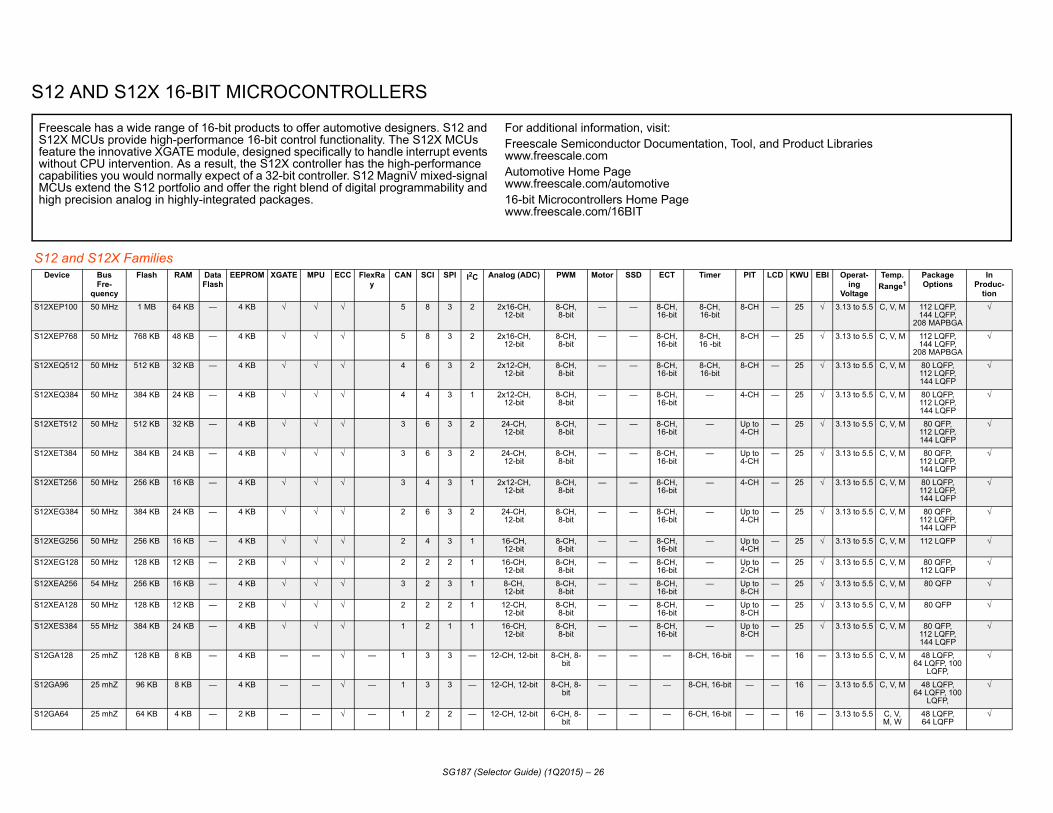
S12 A
S12 anDevice CD KWU EBI Operat-
ingVoltage
Temp. Range1
PackageOptions
InProduc-
tionS12XEP100 — 25 3.13 to 5.5 C, V, M 112 LQFP,
144 LQFP,208 MAPBGA
S12XEP768 — 25 3.13 to 5.5 C, V, M 112 LQFP,144 LQFP,
208 MAPBGA
S12XEQ51 — 25 3.13 to 5.5 C, V, M 80 LQFP,112 LQFP, 144 LQFP
S12XEQ38 — 25 3.13 to 5.5 C, V, M 80 LQFP,112 LQFP,144 LQFP
S12XET512 — 25 3.13 to 5.5 C, V, M 80 QFP,112 LQFP, 144 LQFP
S12XET384 — 25 3.13 to 5.5 C, V, M 80 QFP,112 LQFP, 144 LQFP
S12XET256 — 25 3.13 to 5.5 C, V, M 80 LQFP,112 LQFP,144 LQFP
S12XEG38 — 25 3.13 to 5.5 C, V, M 80 QFP,112 LQFP, 144 LQFP
S12XEG25 — 25 3.13 to 5.5 C, V, M 112 LQFP
S12XEG12 — 25 3.13 to 5.5 C, V, M 80 QFP, 112 LQFP
S12XEA256 — 25 3.13 to 5.5 C, V, M 80 QFP
S12XEA128 — 25 3.13 to 5.5 C, V, M 80 QFP
S12XES384 — 25 3.13 to 5.5 C, V, M 80 QFP,112 LQFP, 144 LQFP
S12GA128 — 16 — 3.13 to 5.5 C, V, M 48 LQFP,64 LQFP, 100
LQFP,
S12GA96 — 16 — 3.13 to 5.5 C, V, M 48 LQFP,64 LQFP, 100
LQFP,
S12GA64 — 16 — 3.13 to 5.5 C, V, M, W
48 LQFP,64 LQFP
FreescS12X MfeaturewithoucapabiMCUs high pr
d Product Libraries
SG187 (Selector Guide) (1Q2015) – 26
ND S12X 16-BIT MICROCONTROLLERS
d S12X Families BusFre-
quency
Flash RAM DataFlash
EEPROM XGATE MPU ECC FlexRay
CAN SCI SPI I2C Analog (ADC) PWM Motor SSD ECT Timer PIT L
50 MHz 1 MB 64 KB — 4 KB 5 8 3 2 2x16-CH,12-bit
8-CH,8-bit
— — 8-CH, 16-bit
8-CH,16-bit
8-CH
50 MHz 768 KB 48 KB — 4 KB 5 8 3 2 2x16-CH,12-bit
8-CH,8-bit
— — 8-CH,16-bit
8-CH,16 -bit
8-CH
2 50 MHz 512 KB 32 KB — 4 KB 4 6 3 2 2x12-CH,12-bit
8-CH,8-bit
— — 8-CH,16-bit
8-CH,16-bit
8-CH
4 50 MHz 384 KB 24 KB — 4 KB 4 4 3 1 2x12-CH,12-bit
8-CH,8-bit
— — 8-CH,16-bit
— 4-CH
50 MHz 512 KB 32 KB — 4 KB 3 6 3 2 24-CH,12-bit
8-CH,8-bit
— — 8-CH,16-bit
— Up to 4-CH
50 MHz 384 KB 24 KB — 4 KB 3 6 3 2 24-CH,12-bit
8-CH,8-bit
— — 8-CH,16-bit
— Up to 4-CH
50 MHz 256 KB 16 KB — 4 KB 3 4 3 1 2x12-CH,12-bit
8-CH,8-bit
— — 8-CH,16-bit
— 4-CH
4 50 MHz 384 KB 24 KB — 4 KB 2 6 3 2 24-CH,12-bit
8-CH,8-bit
— — 8-CH,16-bit
— Up to 4-CH
6 50 MHz 256 KB 16 KB — 4 KB 2 4 3 1 16-CH,12-bit
8-CH,8-bit
— — 8-CH,16-bit
— Up to 4-CH
8 50 MHz 128 KB 12 KB — 2 KB 2 2 2 1 16-CH,12-bit
8-CH,8-bit
— — 8-CH,16-bit
— Up to 2-CH
54 MHz 256 KB 16 KB — 4 KB 3 2 3 1 8-CH,12-bit
8-CH,8-bit
— — 8-CH,16-bit
— Up to 8-CH
50 MHz 128 KB 12 KB — 2 KB 2 2 2 1 12-CH,12-bit
8-CH,8-bit
— — 8-CH,16-bit
— Up to 8-CH
55 MHz 384 KB 24 KB — 4 KB 1 2 1 1 16-CH,12-bit
8-CH,8-bit
— — 8-CH,16-bit
— Up to 8-CH
25 mhZ 128 KB 8 KB — 4 KB — — — 1 3 3 — 12-CH, 12-bit 8-CH, 8-bit
— — — 8-CH, 16-bit —
25 mhZ 96 KB 8 KB — 4 KB — — — 1 3 3 — 12-CH, 12-bit 8-CH, 8-bit
— — — 8-CH, 16-bit —
25 mhZ 64 KB 4 KB — 2 KB — — — 1 2 2 — 12-CH, 12-bit 6-CH, 8-bit
— — — 6-CH, 16-bit —
ale has a wide range of 16-bit products to offer automotive designers. S12 and CUs provide high-performance 16-bit control functionality. The S12X MCUs
the innovative XGATE module, designed specifically to handle interrupt events t CPU intervention. As a result, the S12X controller has the high-performance lities you would normally expect of a 32-bit controller. S12 MagniV mixed-signal extend the S12 portfolio and offer the right blend of digital programmability and ecision analog in highly-integrated packages.
For additional information, visit:Freescale Semiconductor Documentation, Tool, anwww.freescale.comAutomotive Home Pagewww.freescale.com/automotive16-bit Microcontrollers Home Pagewww.freescale.com/16BIT

S12G — 16 — 3.13 to 5.5 C, V, M, W
32 LQFP, 48 LQFP,
64 LQFP
S12G — 16 — 3.13 to 5.5 C, V, M, W
48 LQFP,64 LQFP
S12G — 16 — 3.13 to 5.5 C, V, M, W
32 LQFP, 48 LQFP,
64 LQFP
S12G — 16 — 3.13 to 5.5 C, V, M, W
48 LQFP,64 LQFP
S12G — 16 — 3.13 to 5.5 C, V, M, W
32 LQFP, 48 LQFP,
64 LQFP
S12G — 16 — 3.13 to 5.5 C, V, M, W
48 LQFP
S12G — 16 — 3.13 to 5.5 C, V, M, W
20 TSSOP, 32 LQFP, 48 LQFP, 48 QFN
S12G — 16 — 3.13 to 5.5 C, V, M, W
48 LQFP
S12G — 16 — 3.13 to 5.5 C, V, M, W
20 TSSOP, 32 LQFP, 48
LQFP, 48 QFP
S12G — — — 3.13 to 5.5 M 20 TSSOP, 32 LQFP, 48 LQFP, 48 QFN,64 LQFP, 100 LQFP
S12G — — — 3.13 to 5.5 M 20 TSSOP, 32 LQFP, 48 LQFP, 48 QFN,64 LQFP, 100 LQFP
S12G — — — 3.13 to 5.5 M 20 TSSOP, 32 LQFP, 48 LQFP, 48 QFN,64 LQFP, 100 LQFP
S12G — — — 3.13 to 5.5 M 48 LQFP,64 LQFP,100 LQFP
S12G — — — 3.13 to 5.5 M 48 LQFP,64 LQFP,100 LQFP
S12XS — 18 3.13 to 5.5 C, V,M, J
64 LQFP,80 QFP,
112 LQFP,KGD
S12XS — 18 3.13 to 5.5 C, V,M, J
64 LQFP,80 QFP,
112 LQFP,KGD
S12XS — 18 3.13 to 5.5 C, V,M, J
64 LQP,80 QFP,
112 LQFP,KGD
S12XF — 11 3.13 to 5.5 C, V, M 112 LQFP,64 LQFP
S12XF — 11 3.13 to 5.5 C, V, M 112 LQFP,64 LQFP
S12XF — 11 3.13 to 5.5 C, V, M 112 LQFP,64 LQFP
S12De LCD KWU EBI Operat-
ingVoltage
Temp. Range1
PackageOptions
InProduc-
tion
SG187 (Selector Guide) (1Q2015) – 27
64 25 mhZ 64 KB 4 KB — 2 KB — — — 1 2 2 — 12-CH, 10-bit 6-CH, 8-bit
— — — 6-CH, 16-bit —
A48 25 mhZ 48 KB 4 KB — 1.5 KB — — — 1 2 2 — 12-CH, 12-bit 6-CH, 8-bit
— — — 6-CH, 16-bit —
48 25 mhZ 48 KB 4 KB — 1.5 KB — — — 1 2 2 — 12-CH, 10-bit 6-CH, 8-bit
— — — 6-CH, 16-bit —
NA48 25 mhZ 48 KB 4 KB — 1.5 KB — — — — 2 2 — 12-CH, 12-bit 6-CH, 8-bit
— — — 6-CH, 16-bit —
N48 25 mhZ 48 KB 4 KB — 1.5 KB — — — — 2 2 — 12-CH, 10-bit 6-CH, 8-bit
— — — 6-CH, 16-bit —
NA32 25 mhZ 32 KB 2 KB — 1 KB — — — — 1 1 — 8-CH, 12-bit 6-CH, 8-bit
— — — 6-CH, 16-bit —
N32 25 mhZ 32 KB 2 KB — 1 KB — — — — 1 1 — 8-CH, 12-bit 6-CH, 8-bit
— — — 6-CH, 16-bit —
NA16 25 mhZ 16 KB 1 KB — 512 B — — — — — 1 1 — 8-CH, 12-bit 6-CH, 8-bit
— — — 6-CH, 16-bit —
N16 25 mhZ 16 KB 1 KB — 512 B — — — — 1 1 — 8-CH, 10-bit 6-CH, 8-bit
— — — 6-CH, 16-bit —
192 25 MHz 192 KB 11 KB — 4 KB — — — 1 3 3 — 16-CH, 10-bit 8-CH,8-bit
— — — 8-CH, 16-bit
—
240 25 MHz 240 KB 11 KB — 4 KB — — — 1 3 3 — 16-CH, 10-bit 8-CH,8-bit
— — — 8-CH,16 -bit
—
N32 25 MHz 32 KB 2 KB — 1 KB — — — — 1 1 — 8-CH, 10-bit 6-CH,8-bit
— — — 6-CH, 16-bit
—
128 25 MHz 128 KB 8 KB — 4 KB — — — — 1 3 3 — 12-CH, 10-bit 8-CH,8-bit
— — — 8-CH,16-bit
—
96 25 MHz 96 KB 8 KB — 3 KB — — — — 1 3 3 — 12-CH, 10-bit 8-CH,8-bit
— — — 8-CH,16-bit
—
256 40 MHz 256 KB 12 KB 8 KB — 1 2 1 — 16-CH,12-bit
8-CH,8-bit
— — — 8-CH,16-bit
4-CH
128 40 MHz 128 KB 8 KB 8 KB — 1 2 1 — 16-CH,12-bit
8-CH,8-bit
— — — 8-CH,16-bit
4-CH
64 40 MHz 64 KB 4 KB 4 KB — 1 2 1 — 16-CH,12-bit
8-CH,8-bit
— — — 8-CH,16-bit
4-CH
512 50 MHz 512 KB 32 KB — 4KB 1 2 2 — 16-CH,12-bit
6-CH,15-bit
— — — 8-CH,16-bit
4-CH
384 50 MHz 384 KB 24 KB — 4KB 1 2 2 — 16-CH,12-bit
6-CH,15-bit
— — — 8-CH,16-bit
4-CH
256 50 MHz 256 KB 20 KB — 2 KB 1 2 2 — 16-CH,12-bit
6-CH,15-bit
— — — 8-CH,16-bit
4-CH
and S12X Families (continued)vice Bus
Fre-quency
Flash RAM DataFlash
EEPROM XGATE MPU ECC FlexRay
CAN SCI SPI I2C Analog (ADC) PWM Motor SSD ECT Timer PIT

S 4-CH — 11 3.13 to 5.5 C, V, M 112 LQFP,64 LQFP
S 4-CH 32x4 8 4.5 to 5.5 C, V, M 112 LQFP,144 LQFP
S 4-CH 32x4 8 4.5 to 5.5 C, V, M 112 LQFP,144 LQFP
S 4-CH 32x4 8 4.5 to 5.5 C, V, M 112 LQFP,144 LQFP
S 16-CH., 16-bit
40 x 4
25 - 4.5 to 5.5 C, V, M 100 LQFP,112 LQFP
S 16-CH., 16-bit
40 x 4
25 - 4.5 to 5.5 C, V, M 100 LQFP,112 LQFP
S — — 12 3.13 to 5.5 C, V, M 80 QFP,64 LQFP,48 QFN
S — — 12 3.13 to 5.5 C, V, M 80 QFP,64 LQFP,48 QFN
S — — 12 3.13 to 5.5 C, V, M 80 QFP,64 LQFP,48 QFN
S — — 12 3.13 to 5.5 C, V, M 80 QFP,64 LQFP,48 QFN
S — 32x4 8 4.5 to 5.5 C, V, M 112 LQFP
S — 24x4 8 4.5 to 5.5 C, V, M 80 QFP,112 LQFP
S — 24x4 8 4.5 to 5.5 C, V, M 80 QFP,112 LQFP
S H — 40x4 22 3.13 to 5.5 C, V, M 64 LQFP,100 LQFP
S H — 40x4 22 3.13 to 5.5 C, V, M 64 LQFP,100 LQFP
S H — 40x4 22 3.13 to 5.5 C, V, M 64 LQFP,100 LQFP
S H — 40x4 22 3.13 to 5.5 C, V, M 64 LQFP,100 LQFP
S H — 40x4 22 3.13 to 5.5 C, V, M 64 LQFP,100 LQFP
S H — 40x4 22 3.13 to 5.5 C, V, M 64 LQFP,100 LQFP
1.
SPIT LCD KWU EBI Operat-
ingVoltage
Temp. Range1
PackageOptions
InProduc-
tion
SG187 (Selector Guide) (1Q2015) – 28
12XF128 50 MHz 128 KB 16 KB — 2 KB 1 2 2 — 16-CH,12-bit
6-CH,15-bit
— — — 8-CH,16 -bit
12XHZ512 40 MHz 512 KB 32 KB — 4 KB 2 2 1 2 16-CH,10-bit
8-CH,8-bit
24/6 6 8-CH,16-bit
12XHZ384 40 MHz 384 KB 28 KB — 4 KB 2 2 1 2 16-CH,10-bit
8-CH,8-bit
24/6 6 8-CH,16-bit
12XHZ256 40 MHz 256 KB 16 KB — 4 KB 2 2 1 2 16-CH,10-bit
8-CH,8-bit
24/6 6 8-CH,16-bit
—
12XHY256 40 MHz 256 KB 12 KB 8 KB - - 2 2 1 - 12-ch., 10-bit
8-CH,8-bit/ 4-CH,16-bit
16/4 4 - -
12XHY128 40 MHz 128 KB 8KB 8 KB - - 2 2 1 - 12-ch., 10-bit
8-CH,8-bit/ 4-CH,16-bit
16/4 4 - -
12P128 32 MHz 128 KB 6 KB 4 KB — 1 1 1 — 10-CH,12-bit
6-CH,8-bit
— — — 8-CH,16 -bit
12P96 32 MHz 96 KB 6 KB 4 KB — 1 1 1 — 10-CH,12-bit
6-CH,8-bit
— — — 8-CH,16 -bit
12P64 32 MHz 64 KB 4 KB 4 KB — 1 1 1 — 10-CH,12-bit
6-CH,8-bit
— — — 8-CH,16-bit
12P32 32 MHz 32 KB 2 KB 4 KB — 1 1 1 — 10-CH,12-bit
6-CH,8-bit
— — — 8-CH,16-bit
12HZ128 25 MHz 128 KB 6 KB — 2 KB 2 2 1 1 16-CH,10-bit
6-CH,8-bit
16/4 4 — 8-CH,8-bit
12HZ64 25 MHz 64 KB 4 KB — 1 KB 1 1 1 — 8-CH,10-bit
4-CH,8-bit
16/4 4 — 8-CH,8-bit
12HN64 25 MHz 64 KB 4 KB — 1 KB 1 1 — 8-CH,10-bit
4-CH,8-bit
16/4 4 — 8-CH,8-bit
12HY64 32 MHz 64 KB 4 KB 4 KB — 1 1 1 1 8-CH,10-bit
8-CH,8-bit
16/4 Support — 8-CH+8-C16-bit
12HA64 32 MHz 64 KB 4 KB 4 KB — 1 1 1 8-CH,10-bit
8-CH,8-bit
16/4 Support — 8-CH+8-C16-bit
12HY48 32 MHz 48 KB 4 KB 4 KB — 1 1 1 1 8-CH,10-bit
8-CH,8-bit
16/4 Support — 8-CH+8-C16-bit
12HA48 32 MHz 48 KB 4 KB 4 KB — 1 1 1 8-CH,10-bit
8-CH,8-bit
16/4 Support — 8-CH+8-C16-bit
12HY32 32 MHz 32 KB 2 KB 4 KB — 1 1 1 1 8-CH,10-bit
8-CH,8-bit
16/4 Support — 8-CH+8-C16-bit
12HA32 32 MHz 32 KB 2 KB 4 KB — 1 1 1 8-CH,10-bit
8-CH,8-bit
16/4 Support — 8-CH+8-C16-bit
C = -40 °C to +85 °C, V = -40 °C to +105 °C, M = -40 °C to +125 °C, J = -40 °C to +140 °C, W = -40 °C to +150 °C
12 and S12X Families (continued)Device Bus
Fre-quency
Flash RAM DataFlash
EEPROM XGATE MPU ECC FlexRay
CAN SCI SPI I2C Analog (ADC) PWM Motor SSD ECT Timer

S12D Vreg Ext.
SupplyOperating
VoltageTemp.
Range1PackageOptions
InProduc-
tionS12ZV 2 5.0 V/20
mAC, M, V,
W64 LQFP-
EP, 48 LQFP
S12ZV 2 5.0 V/20 mA
C, M, V, W
64 LQFP-EP, 48 LQFP
S12ZV 2 5.0 V/20 mA
C, M, V, W
64 LQFP-EP, 48 LQFP
S12ZV 2 5.0 V/20 mA
C, M, V, W
64 LQFP-EP, 48 LQFP
S12ZV 2 5.0 V/20 mA
C, M, V, W
64 LQFP-EP, 48 LQFP
S12ZV 2 5.0 V/20 mA
C, M, V, W
64 LQFP-EP, 48 LQFP
S12ZV 2 5.0 V/20 mA
C, M, V, W
64 LQFP-EP, 48 LQFP
S12ZV 2 5.0 V/20 mA
C, M, V, W
64 LQFP-EP, 48 LQFP
S12ZV 1 5.0 V/20 mA
C, V, M 48 LQFP, 32-LQFP
S12ZV 1 5.0 V/20 mA
C, V, M 48 LQFP, 32-LQFP
S12ZV 1 5.0 V/20 mA
C, V, M 48 LQFP, 32-LQFP
S12ZV 1 5.0 V/20 mA
C, V, M 32 QFN
S12ZV 1 5.0 V/20 mA
C, V, M 32 QFN
S12VR 2 5.0 V, 20 mA
6.0 to 18 C, V 32 LQFP,48 LQFP
S12VR 2 5.0 V, 20 mA
6.0 to 18 C, V 32 LQFP,48 LQFP
S12ZV 2 5.5 V to 18 V
C, V 100 LQFP, 144 LQFP
S12ZV 2 5.5 V to 18 V
C, V 144 LQFP
S12ZV 1 5.5 V to 18 V
C, V 100 LQFP, 144 LQFP
S12ZV 1 5.5 V to 18 V
C, V 100 LQFP, 144 LQFP
S12ZV 1 5.5 V to 18 V
C, V 100 LQFP, 144 LQFP
SG187 (Selector Guide) (1Q2015) – 29
MagniV Mixed-signal MCUs evice Bus
Fre-quency
Flash RAM EEPROM ECC CAN CAN-PHY
SCI LIN-PHY
SPI I2C Ext. Ana-log (ADC)
Int. Ana-log (ADC)
PWM Timer LCD KWU Motor High Volt-age Input
Other Analog
CA192 32 MHz 192 KB 12 KB 2 KB 1 1 2 — 2 1 16-CH, 12-bit
4+4-CH, 16-bit
8+4-CH, 16-bit
— 34 — 2-CH HVI, Vsup Sense
2-CH ACMP, DAC
CA128 32 MHz 128 KB 12 KB 2 KB 1 1 2 — 2 1 16-CH, 12-bit
4+4-CH, 16-bit
8+4-CH, 16-bit
— 34 — 2-CH HVI, Vsup Sense
2-CH ACMP, DAC
CA96 32 MHz 96 KB 12 KB 2 KB 1 1 2 — 2 1 16-CH, 12-bit
4+4-CH, 16-bit
8+4-CH, 16-bit
— 34 — 2-CH HVI, Vsup Sense
2-CH ACMP, DAC
CA64 32 MHz 64 KB 4 KB 1 KB 1 1 2 — 2 1 16-CH, 12-bit
4+4-CH, 16-bit
8+4-CH, 16-bit
— 34 — 2-CH HVI, Vsup Sense
2-CH ACMP, DAC
C192 32 MHz 192 KB 12 KB 2 KB 1 1 2 — 2 1 16-CH, 10-bit
4+4-CH, 16-bit
8+4-CH, 16-bit
— 34 — 2-CH HVI, Vsup Sense
—
C128 32 MHz 128 KB 12 KB 2 KB 1 1 2 — 2 1 16-CH, 10-bit
4+4-CH, 16-bit
8+4-CH, 16-bit
— 34 — 2-CH HVI, Vsup Sense
—
C96 32 MHz 96 KB 12 KB 2 KB 1 1 2 — 2 1 16-CH, 10-bit
4+4-CH, 16-bit
8+4-CH, 16-bit
— 34 — 2-CH HVI, Vsup Sense
—
C64 32 MHz 64 KB 4 KB 1 KB 1 1 2 — 2 1 16-CH, 10-bit
4+4-CH, 16-bit
8+4-CH, 16-bit
— 34 — 2-CH HVI, Vsup Sense
—
L32 32 MHz 32 KB 1 KB 128 B — — 2 1 1 1 10-CH, 10-bit
8-CH, 8-bit or 4-CH, 16-
bit
6+2-CH, 16-bit
— 23 — 1-CH HVI, Vsup Sense
3-CH NGPIO
(5.0 V/25 mA)
L16 32 MHz 16 KB 1 KB 128 B — — 2 1 1 1 10-CH, 10-bit
8-CH, 8-bit or 4-CH, 16-
bit
6+2-CH, 16-bit
— 23 — 1-CH HVI, Vsup Sense
3-CH NGPIO
(5.0 V/25 mA)
L8 32 MHz 8 KB 1 KB 128 B — — 2 1 1 1 10-CH, 10-bit
8-CH, 8-bit or 4-CH, 16-
bit
6+2-CH, 16-bit
— 23 — 1-CH HVI, Vsup Sense
3-CH NGPIO
(5.0 V/25 mA)
LS32 32 MHz 32 KB 1 KB 128 B — — 2 1 1 1 10-CH, 10-bit
8-CH, 8-bit or 4-CH, 16-
bit
6+2-CH, 16-bit
— 23 — 1-CH HVI, Vsup Sense
3-CH NGPIO
(5.0 V/25 mA)
LS16 32 MHz 16 KB 1 KB 128 B — — 2 1 1 1 10-CH, 10-bit
8-CH, 8-bit or 4-CH, 16-
bit
6+2-CH, 16-bit
— 23 — 1-CH HVI, Vsup Sense
3-CH NGPIO
(5.0 V/25 mA)
64 25 MHz 64 KB 2 KB 512 B — — 2 1 1 — 6-CH, 10-bit 4-CH, 10-bit
4-CH, 8-bit
4-CH, 16 -bit
— 6 2-CH Relay, LS
Driver
4-CH HVI, Vbat-Sense, Vsup Sense
2-CH, HS
Driver48 25 MHz 48 KB 2 KB 512 B — — 2 1 1 — 6-CH, 10-bit 4-CH, 10-
bit 4-CH, 8-
bit4-CH, 16 -bit
— 6 2-CH Relay, LS
Driver
4-CH HVI, Vbat-Sense, Vsup Sense
2-CH, HS
DriverH128 32 MHz 128KB 8 KB 4 KB 1 1 2 — 1 1 8-CH, 10-bit 8-CH, 10-
bit8-CH(8-bit), 4-CH(16-
bit)
Two 8-CH x16-
bit
4x40 24 4 Stepper Vbat-Sense, Vsup-Sense
—
H64 32 MHz 64 KB 4 KB 4 KB 1 1 2 — 1 1 8-CH, 10-bit 8-CH, 10-bit
8-CH(8-bit), 4-CH(16-
bit)
Two 8-CH x16-
bit
4x40 24 4 Stepper Vbat-Sense, Vsup-Sense
—
HY64 32 MHz 64 KB 4 KB 2 KB 1 — 2 — 1 1 8-CH, 10-bit 8-CH, 10-bit
8-CH(8-bit), 4-CH(16-
bit)
Two 8-CH x16-
bit
4x40 24 2 Stepper Vbat-Sense, Vsup-Sense
—
HY32 32 MHz 32 MHz
2 KB 2 KB 1 — 2 — 1 1 8-CH, 10-bit 8-CH, 10-bit
8-CH (8-bit), 4-
CH (16-bit)
Two 8-CH x 16-
bit
4x40 24 2 Stepper Vbat-Sense, Vsup-Sense
—
HL64 32 MHz 64 KB 4 KB 2 KB 1 — 2 1 1 1 8-CH, 10-bit 8-CH, 10-bit
8-CH (8-bit), 4-
CH (16-bit)
Two 8-CH x 16-
bit
4x40 24 2 Stepper Vbat-Sense, Vsup-Sense
—

S12ZVFP64 e, e
— 1 5.5 V to 18 V
C, V 100 LQFP, 144 LQFP
S12ZVML1 e 6-CH Gate Drive Unit
2 — 3.5 V to 20 V
V, M, W 64 LQFP-EP
S12ZVMC1 e 6-CH Gate Drive Unit
2 — 3.5 V to 20 V
V, M, W 64 LQFP-EP
S12ZVML6 e 6-CH Gate Drive Unit
1 — 3.5 V to 20 V
V, M, W 64 LQFP-EP
S12ZVMC6 e 6-CH Gate Drive Unit
2 — 3.5 V to 20 V
V, M, W 64 LQFP-EP
S12ZVML3 e 1 5.0 V, 20 mA
3.5 V to 20 V
V, M, W 64 LQFP-EP
S12ZVM32 e HV-PHY 1 5.0 V, 20 mA
3.5 V to 20 V
V, M, W 64 LQFP-EP, 48
LQFP-EPS12ZVM16 e HV-PHY 1 5.0 V, 20
mA3.5 V to 20
VV, M, W 64 LQFP-
EP, 48 LQFP-EP
1. C = -40
S12 MaDevice -
tOther
AnalogVreg Ext.
SupplyOperating
VoltageTemp.
Range1PackageOptions
InProduc-
tion
SG187 (Selector Guide) (1Q2015) – 30
32 MHz 64 KB 4 KB 2 KB 1 — 2 1 1 1 8-CH, 10-bit 8-CH, 10-bit
8-CH (8-bit), 4-
CH (16-bit)
Two 8-CH x 16-
bit
4x40 24 — Vbat-SensVsup-Sens
28 50 MHz 128 KB 8 KB 512 B 1 — 2 1 1 — 4+5-CH, 12-bit
8-CH, 12-bit
6-CH, 15-bit
4-CH, 16-bit
— 6 BLDC/PMSM
Vsup-Sens
28 50 MHz 128 KB 8 KB 512 B 1 — 2 — 1 — 4+5-CH, 12-bit
8-CH, 12-bit
6-CH, 15-bit
4-CH, 16-bit
— 6 BLDC/PMSM
Vsup-Sens
4 51 MHz 64 KB 4 KB 512 B 1 — 2 1 1 — 4+5-CH, 12-bit
8-CH, 12-bit
6-CH, 15-bit
4-CH, 16-bit
— 6 BLDC/PMSM
Vsup-Sens
4 52 MHz 64 KB 4 KB 512 B 1 — 2 — 1 — 4+5-CH, 12-bit
8-CH, 12-bit
6-CH, 15-bit
4-CH, 16-bit
— 6 BLDC/PMSM
Vsup-Sens
2 50 MHz 32 KB 4 KB 512 B 1 — 2 1 1 4+5-CH, 12-bit
8-CH, 12-bit
6-CH, 15-bit
4-CH, 16-bit
6 BLDC/PMSM
Vsup-Sens
50 MHz 32 KB 4 KB 128 B — 1 1 4+5-CH, 12-bit
8-CH, 12-bit
6-CH, 15-bit
4-CH, 16-bit
6 BLDC/PMSM
Vsup-Sens
50 MHz 16 KB 2 KB 128 B 1 1 4+5-CH, 12-bit
8-CH, 12-bit
6-CH, 15-bit
4-CH, 16-bit
6 BLDC/PMSM
Vsup-Sens
°C to +85 °C, V = -40 °C to +105 °C, M = -40 °C to +125 °C, J = -40 °C to +140 °C, W = -40 to +150 °C
gniV Mixed-signal MCUs (continued)BusFre-
quency
Flash RAM EEPROM ECC CAN CAN-PHY
SCI LIN-PHY
SPI I2C Ext. Ana-log (ADC)
Int. Ana-log (ADC)
PWM Timer LCD KWU Motor High Voltage Inpu

DIG
56F
KIN
56the56comsafpe
flash and RAM, data flash and RAM, and The modified Harvard architecture enables mory accesses. the controller devices including software, evelopment tools.
P perature Packaging Additional Information
56F80 C, M 32-pin LQFP mcPWM with center alignment,1 x 4 channel Quad Decoder
56F83 C, M 128-pin LQFP mcPWM with center alignment,2 x 4 channel Quad Decoder
KineD rating
ltageTemp Range
Debug PackageOptions
InProduc-
tion
KEAZ to 5.5 C, V, M SWD 16 TSSOP, 24 QFN
KEAZ to 5.5 C, V, M SWD 32 LQFP, 64 LQFP
KEAZ to 5.5 C, V, M SWD 32 LQFP, 64 LQFP
KEAZ to 5.5 C, V, M SWD 32 LQFP, 64 LQFP
KEAZ to 5.5 C, V, M SWD 64 LQFP, 80 LQFP
KEAZ to 5.5 C, V, M SWD 64 LQFP, 80 LQFP
Kinproof Dethe
SG187 (Selector Guide) (1Q2015) – 31
ITAL SIGNAL CONTROLLERS
8xxx Family
ETIS MCUS BASED ON ARM® TECHNOLOGY
800E Core—The 56800E MCU+DSP core was architected specifically to provide users ease of use of an MCU together with the performance of a DSP in a single core.
F8300 High-Performance Flash Series—The MC56F8300 series of controllers bines the 56800E core with flash memory, motor control peripherals, and built-in
ety features targeted specifically for automotive applications to provide 60 MIPS of rformance over the full -40°C to 125°C temperature range.
Memory—On-board memory includes programBootFlash with EEPROM emulation capability.users to perform up to three simultaneous meService—A full-range of services is offered forsupport, training, and internal and third-party dFor additional information, visit:Documentation, Tool, and Product Libraries:www.freescale.com
roduct ROM (KB)
RAM Flash Timer Serial GPIO (pins)
A/D PWM Operating Voltage
(V)
OperatingFrequency
(MHZ)
Tem
13 0 4K 16K 4 x 16-bit 1 SCI/LIN + 1 SPI + 1 I2C 26 1 x 4-CH12-bit
1 x 6-CH 3.3 32
55 n/a 20K 280K 16 x 16-bit 2 SCI/LIN + 2 SPI + 1 CAN + 1 I2C 49 4 x 4-CH12-bit
2 x 6-CH 3.3 60
tis MCUs based on ARM® Technologyevice Core
PlatformProgram
FlashRAM EEPROM SCI SPI CAN I2C Other
Commu-nications
Timer Analog (ADC)
KBI Additional Features
OpeVo
N8 48 MHz 8 KB 1 KB Emulate 1 1 0 1 - FTM, PIT, PWT, RTC
12-CH, 12-bit 2x 8-bit LVD, BME, ACMP, PMC,
CRC
2.7
N16 40 MHz 16 KB 2 KB 256 B 3 2 0 2 - FTM, PIT, RTC 16-CH, 12-bit 2x 8-bit LVD, BME, ACMP, PMC,
CRC
2.7
N32 40 MHz 32 KB 4 KB 256 B 3 2 0 2 - FTM, PIT, RTC 16-CH, 12-bit 2x 8-bit LVD, BME, ACMP, PMC,
CRC
2.7
N64 40 MHz 64 KB 4 KB 256 B 3 2 0 2 - FTM, PIT, RTC 16-CH, 12-bit 2x 8-bit LVD, BME, ACMP, PMC,
CRC
2.7
64 48 MHz 64 KB 8 KB Emulate 3 2 1 2 - FTM, PIT, PWT, RTC
16-CH, 12-bit 2x 32-bit LVD, BME, ACMP, PMC,
CRC
2.7
128 48 MHz 128 KB 16 KB Emulate 3 2 1 2 - FTM, PIT, PWT, RTC
16-CH, 12-bit 2x 32-bit LVD, BME, ACMP, PMC,
CRC
2.7
etis MCU families for automotive are based on ARM® Cortex Technology and vide high scalability, cost-effective automotive-grade 32-bit portfolio for a wide range
automotive applications. signers will be benefited from the granted third party support for ARM technology and y will maximize hardware and software reuse.
For additional information, visit:Documentation, Tool, and Product Librarieswww.freescale.comAutomotive Home Pagewww.freescale.com/automotive
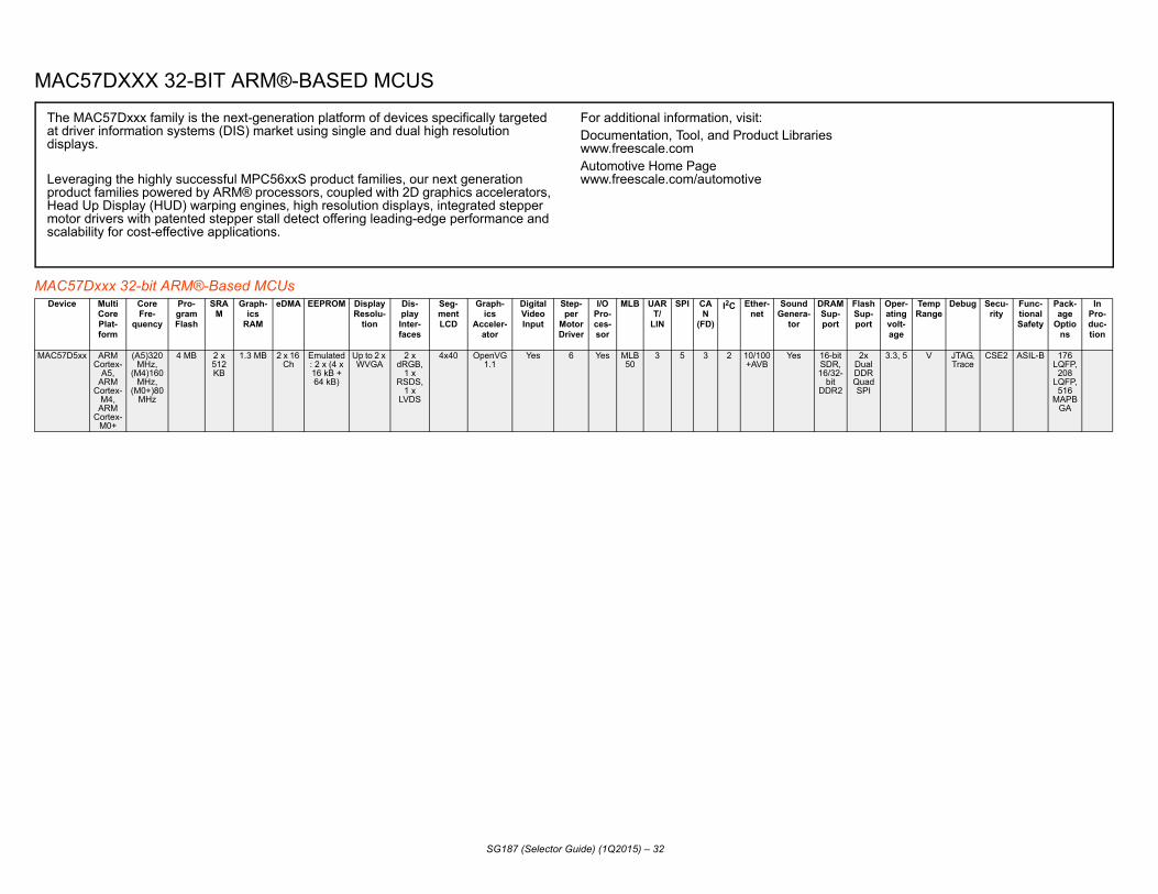
MA
MACDev
-Flash Sup-port
Oper-ating volt-age
Temp Range
Debug Secu-rity
Func-tional Safety
Pack-age
Options
InPro-duc-tion
MAC5 it , -
2
2x Dual DDR Quad SPI
3.3, 5 V JTAG, Trace
CSE2 ASIL-B 176 LQFP, 208
LQFP, 516
MAPBGA
That dis
LeproHemosc
SG187 (Selector Guide) (1Q2015) – 32
C57DXXX 32-BIT ARM®-BASED MCUS
57Dxxx 32-bit ARM®-Based MCUsice Multi
CorePlat-form
Core Fre-
quency
Pro-gram Flash
SRAM
Graph-ics
RAM
eDMA EEPROM Display Resolu-
tion
Dis-play Inter-faces
Seg-ment LCD
Graph-ics
Acceler-ator
Digital Video Input
Step-per
Motor Driver
I/O Pro-ces-sor
MLB UART/
LIN
SPI CAN
(FD)
I2C Ether-net
Sound Genera-
tor
DRAMSupport
7D5xx ARM Cortex-
A5, ARM
Cortex-M4,
ARM Cortex-
M0+
(A5)320 MHz,
(M4)160 MHz,
(M0+)80 MHz
4 MB 2 x 512 KB
1.3 MB 2 x 16 Ch
Emulated: 2 x (4 x 16 kB + 64 kB)
Up to 2 x WVGA
2 x dRGB,
1 x RSDS,
1 x LVDS
4x40 OpenVG 1.1
Yes 6 Yes MLB50
3 5 3 2 10/100 +AVB
Yes 16-bSDR16/32
bit DDR
e MAC57Dxxx family is the next-generation platform of devices specifically targeted driver information systems (DIS) market using single and dual high resolution plays.
veraging the highly successful MPC56xxS product families, our next generation duct families powered by ARM® processors, coupled with 2D graphics accelerators, ad Up Display (HUD) warping engines, high resolution displays, integrated stepper tor drivers with patented stepper stall detect offering leading-edge performance and
alability for cost-effective applications.
For additional information, visit:Documentation, Tool, and Product Librarieswww.freescale.comAutomotive Home Pagewww.freescale.com/automotive

QO
32-bDev Ana-
log (ADC, DAC)
Operat-ing
Voltage
Temp.Range1
Debug PackageOptions
InProduc-
tion
MPC5 xDelta Sigma @ 10 MHz;
4x12bit AR @ 1Mz; M/s 8-it DAC
3.3 V I/O, 1.2 V
Core
-40 to 150 Tj
Nexus 3+ 17x17 356
PBGA
MPC5 xDelta Sigma @ 10 MHz;
4x12bit AR @ 1Mz; M/s 8-it DAC
3.3 V I/O, 1.2 V
Core
-40 to 150 Tj
Nexus 3+ 17x17 356
PBGA
MPC5 Quad, 25-ch. xterna
, 12-bit
3.3 C, V, M Nexus 3+, MDO and
Aurora interface
144 LQFP,257
MAPBGA
MPC5 4 x SAR, 3 x SD
3.3, 5 M Nexus 3+, JTAG
176 LQFP-
EP252
MAPBGA
MPC5 8 x SAR, 6 x SD
3.3, 5 M Nexus 3+, ZipwireAurora, JTAG
176 LQFP-
EP292
MAPBGA
MPC5 Up to 32-CH, 12-bit, 48-CH, 10-bit
3.3 V, 5.0 V
C, V, M Nexus 3+ 176 LQFP, 256
MApBGA,
324 MAPBG
AMPC5 Up to
32-CH, 12-bit, 48-CH, 10-bi
3.3 V, 5.0 V
C, V, M Nexus 3+ 176 LQFP, 256
MApBGA,
324 MAPBG
A
Poboaudeneopauex
SG187 (Selector Guide) (1Q2015) – 33
RIVVA 32-BIT MCUS BASED ON POWER ARCHITECTURE® TECHNOLOGY
it Qorivva MPC56xx and MPC57xx MCUs Built on Power Architecture® Technology ice Core
Plat-form
Bus Fre-
quency
Pro-gramFlash
SRAM DMA EEPROM MPU/MMU
CTU SCI(LIN-Flex)
DSPI
CAN I2C FlexRay™
Ethernet(100BaseT)
MLB Other Periph-erals
eTPU eMIOS Motor ControlTimers
PIT
775K Dual Z7 Process
or, lockstep
Z4
Z7 cores at
266 Mhz, Z4
cores at 133 MHz
4 MB with ECC
1.5 MB with ECC
Safe DMA
No No No 4 4 4 of which 1 is FD
3 128 msg
1 No SPT (Signal Processing
Unit) for Radar
Algorithms, 2xCross Trig
Unit, 3xeTimers, 2xSENT,
Temp Sensor
No No 2xPWM No 8
S
2b
774K Dual Z7 Process
or, lockstep
Z4
Z7 cores at
266 Mhz, Z4
cores at 133 MHz
3 MB with ECC
1.0 MB with ECC
Safe DMA
No No No 4 4 4 of which 1 is FD
3 128 msg
1 No SPT (Signal Processing
Unit) for Radar
Algorithms, 2xCross Trig
Unit, 3xeTimers, 2xSENT,
Temp Sensor
No No 2xPWM No 8
S
2b
744P 2 x e200z4
180 MHz
2.5 MB 384 KB 32-CH Emulated in
Program Flash
32 Entry 2 4 3 (3 x 6-ch., E-Timer), (2 x 12-
ch, PWM)
4-CH
El
746R 3 x e200z4
3 x 200 MHz
4 MB 320 KB 64-CH 288 KB MPU 6 7 4 \ Zipwire, SENT
64-CH 32-CH 8
746M 4 x e200z4
4 x 200 MHz
4 MB 320 KB 64-CH 288 KB Yes, No 5 7 3/1 1 120-CH
746G Dual e200z7
2x180 MHz
6 MB 384 KB 96-CH 64 KB Data Flash
32 entry 3 10 8 4 Up to 96-CH, 16-bit
16
747C e200x4, e200x2
180 MHz,
80 MHz
4 MB 512 KB 32-CH Emulated 24-CH MPU
Up to 16
10 8 4 Up to 96-CH, 16-bit
16
wer Architecture is the world's leading architecture for automotive powertrain control, dy electronics, safety and chassis, and instrument cluster applications. Our tomotive qualified 32-bit Qorivva processors built on Power Architecture technology liver highly integrated single and multicore solutions for many automotive design eds. With Qorivva microcontrollers, you get a full range of performance and memory tions so you can design scalable applications for more fuel-efficient, safer and secure tomobiles.The Qorivva MPC56xx portfolio will continue to grow with devices that offer panded sets of memory, connectivity and performance options.
For additional information, visit:Documentation, Tool, and Product Librarieswww.freescale.comAutomotive Home Pagewww.freescale.com/automotiveQorivva Home agewww.freescale.com/Qorivva

MPC5747G Up to 32-CH, 12-bit, 48-CH, 10-bi
3.3 V, 5.0 V
C, V, M Nexus 3+ 176 LQFP, 256
MAPBGA,
324 MAPBG
A
MPC5748C Up to 32-CH, 12-bit, 48-CH, 10-bi
3.3 V, 5 V
C, V, M Nexus 3+ 176 LQFP, 256
MAPBGA,
324 MAPBG
A
MPC5748G Up to 32-CH, 12-bit, 48-CH, 10-bi
3.3V, 5V C, V, M Nexus 3+ 176 LQFP, 256
MAPBGA,
324 MAPBG
A
MPC5777M 12 x SAR,
10 x SD
3.3, 5 M Nexus 3+, ZipwireAurora, JTAG
416 PBGA,
512 PBGA
MPC5676R Up to 64-CH, 12-bit
12 xDEC Filters
3.3V, 5V M Nexus 3+ 416 BGA,
516 BGA
MPC5674F Quad 64-CH
3.3 V, 5.0 V
M Nexus 3+ 324 BGA,416
BGA, 516 BGA
MPC5673F Quad 64-CH
3.3 V, 5 V
M Nexus 3+ 324 BGA,416
BGA, 516 BGA
MPC5673K 4 x 12-bit,,34-
CH
3.3 V, 1.2 V
C, V, M Nexus 3+ 257 MAPBG
A,473
MAPBGA
MPC5675K 4-CH, 12-bit
3.3 V, 5 V
M, V Nexus 3+ 473 MAPBG
A, 275
MAPBGA
MPC5674K 4 x 12-bit, 34-
CH
3.3 V, 5.0 V
C, V, M Nexus 3+ 257 MAPBG
A,473
MAPBGA
MPC5668G 36-CH, 10-bit
3.3 V, 5.0 V
V Nexus3 on z6 and
Nexus 2+
208 MAPBG
A
32-bit QDevice Ana-
log (ADC, DAC)
Operat-ing
Voltage
Temp.Range1
Debug PackageOptions
InProduc-
tion
SG187 (Selector Guide) (1Q2015) – 34
Dual e200x4, e200x2
180 MHz,
80 MH
4 MB 768 KB 32-CH Emulated 32-CH MPU
Up to 18
10 8 4 USB Up to 96-CH, 16-bit
16
e200x4, e200x2
180 MHz,
80 MH
6 MB 768 KB 32-CH Emulated 24-CH MPU
Up to 16
10 8 4 Up to 96-CH, 16-bit
16
Dual e200x4, e200x2
180 MHz,
80 MH
6 MB 768 KB 32-CH Emulated 32-CH MPU
Up to 18
10 8 4 USB Up to 96-CH, 16-bit
16
3 x e200z7 + 1 x
e200z4
3 x 300 MHz +
1 x 200MH
z
8 MB 596 KB 128-CH
8 x 64 KB Yes, No 6 8 4/1 2 248-CH
Dual e200z7
2x180 MHz
6 MB 384 KB 96-CH 64 KB Data Flash
32 entry 3 5 4 96-CH Up to 32-CH, 16-bit
e200z7 150, 200, 264 MHz
4 MB 256 KB 64-CH + 32-CH
Emulatedin
ProgramFlash
MPU+ 64Entry MMU
3 4(MSB)
4 2x32-CH
32-CH
e200z7 150, 200, 264 MHz
3 MB 192 KB 64-CH + 32-CH
Emulatedin
ProgramFlash
MPU+ 64Entry MMU
3 4(MSB)
4 2x32-CH
32-CH
Dual e200z7
2x180 MHz
1 MB 256 KB 2x 32-CH
64 KB 3 2 4 2 3 x PWM;
3 x ETIMER
1
Dual e200z7d
45 MHz 2 MB 512 KB 32-CH Emulatedin
ProgramFlash
64 entry 4 3 4 3 opt. 4-CH
Dual e200z7d
180 MHz
1.5 MB 384 KB 2 x 32-CH
64KB 2 4 3 4 3 3 x PWM;
3 x ETIMER
4-CH
e200z6 +
e200z0
116 MHz
2 MB 592KB 16-CH 64 KB 6 4 6 4 16-CH, 24-bit
8-CH
orivva MPC56xx and MPC57xx MCUs Built on Power Architecture® Technology (continued)CorePlat-form
Bus Fre-
quency
Pro-gramFlash
SRAM DMA EEPROM MPU/MMU
CTU SCI(LIN-Flex)
DSPI
CAN I2C FlexRay™
Ethernet(100BaseT)
MLB Other Periph-erals
eTPU eMIOS Motor ControlTimers
PIT

MPC5 64-CH, 10-bit
3.3 V, 5.0 V
V, M JTAG, Nexus3
onz6 and Nexus2+
208 MAPBG
A, 256
MAPBGA only for
devt.
MPC5 8-CH, 10-bit
3.0 V, 1.2 V
C, V, M Nexus 2+ 64 LQFP
MPC5 Dual34-CH,12-bit
5.0 V M Nexus 2+ Wide trace
port in Vertical
Calibration System
144 LQFP,176
LQFP,208
MAPBGA
MPC5 Dual34-CH,12-bit
5.0 V M Nexus 2+ Wide trace
port in Vertical
Calibration System
100 LQFP,144
LQFP,176
LQFP,208
MAPBGA
MPC5 Dual32-CH,12-bit
5.0 V M Nexus 2+ Wide trace
port in Vertical
Calibration System
100 LQFP,144
LQFP
MPC5 . Dual 16-Ch., 12-bit
3.3 V M Nexus 3+ 144 LQFP, 257
MAPBGA
MPC5 Up to 29-CH, 12-bit, Up to
33-CH, 10-bit
3.3 V, 5.0 V
C, V, M Nexus 3+ 256 BGA, 208
LQFP, 176
LQFP
MPC5 Up to 29-CH, 12-bit, Up to
33-CH, 10-bit
3.3 V, 5.0 V
C, V, M Nexus 3+ 256 BGA, 208
LQFP, 176
LQFP
MPC5 Up to 29-CH, 12-bit, Up to
33-CH, 10-bit
3.3 V, 5.0 V
C, V, M Nexus 3+ 256 BGA, 208
LQFP, 176
LQFP
MPC5 Up to 29-CH, 12-bit, Up to
33-CH, 10-bit
3.3 V, 5.0 V
C, V, M Nexus 3+ 256 BGA, 208
LQFP, 176
LQFP
MPC5 Up to 29-CH, 12-bit, Up to
33-CH, 10-bit
3.3 V, 5.0 V
C, V, M Nexus 3+ 256 BGA, 208
LQFP, 176
LQFP
MPC5 Up to 29-CH, 12-bit, Up to
33-CH, 10-bit
3.3 V, 5.0 V
C, V, M Nexus 3+ 256 BGA, 208
LQFP, 176
LQFP
32-bDev Ana-
log (ADC, DAC)
Operat-ing
Voltage
Temp.Range1
Debug PackageOptions
InProduc-
tion
SG187 (Selector Guide) (1Q2015) – 35
668E e200z0 +
e200z0
116 MHz
2 MB 128 KB 32-CH Emulatedin
ProgramFlash
16 entry 12 4 5 4 32-CH, 16-bit
8-CH
604E e200z0h 64 MHz 512 KB 96 KB 16-CH 64 KB yes 2 3 1 3 1 x E-Timer
1
634M e200z3 60, 80MHz
1.5M 94 KB 32-CH Emulatedin
ProgramFlash
8 Entry 2 2 2 0 32-CH 16-CH, 24-bit
5-CH
633M e200z3 40, 60,80 MHz
1M 64 KB 32-CH Emulatedin
ProgramFlash
8 Entry 2 2 2 0 32-CH 16-CH, 24-bit
5-CH
632M e200z3 40, 60MHz
768 KB 48 KB 32-CH Emulatedin
ProgramFlash
8 Entry 2 2 2 0 32-CH 8-CH, 24-bit
5-CH
643L e200z4x2
80/120 MHz
1 MB 128 KB 16-CH 64 KBData Flash
16 Entry 2 3 2 0 46-Ch. eTimer/PWM/STM
4-Ch
646C e200z4 +
e200z0
120 MHz,
60 MHz
3 MB 256 KB 16-CH 64 KB Data Flash
16 Entry 10 8 6 1 64-CH, 16-bit
Up to8-CH
646B e200z4 120 MHz
3 MB 192 KB 16-CH 64 KB Data Flash
16 Entry 10 8 6 1 64-CH, 16-bit
Up to8-CH
645C e200z4 +
e200z0
120 MHz,
60 MHz
2 MB 256 KB 16-CH 64 KB Data Flash
16 Entry 10 8 6 1 64-CH, 16-bit
Up to8-CH
645B e200z4 120 MHz
2 MB 160 KB 16-CH 64 KB Data Flash
16 Entry 10 8 6 1 64-CH, 16-bit
Up to8-CH
644C e200z4 +
e200z0
120 MHz,
60 MHz
1.5 MB 192 KB 16-CH 64 KB Data Flash
16 Entry 10 8 6 1 64-CH, 16-bit
Up to8-CH
644B e200z4 120 MHz
1.5 MB 128 KB 16-CH 64 KB Data Flash
16 Entry 10 8 6 1 64-CH, 16-bit
Up to8-CH
it Qorivva MPC56xx and MPC57xx MCUs Built on Power Architecture® Technology (continued)ice Core
Plat-form
Bus Fre-
quency
Pro-gramFlash
SRAM DMA EEPROM MPU/MMU
CTU SCI(LIN-Flex)
DSPI
CAN I2C FlexRay™
Ethernet(100BaseT)
MLB Other Periph-erals
eTPU eMIOS Motor ControlTimers
PIT

MPC5607B 16-CH, 10/12-
bit & up to 32-
Ch., 10-bit
3.3 V, 5.0 V
C, V, M Nexus 2+ (208MAPBGA Emul.
Only Package)
JTAG
100 LQFP, 144
LQFP, 176
LQFP
MPC5606B 16-CH, 10/12-
bit & up to 32-
Ch., 10-bit
3.3 V, 5.0 V
C, V, M Nexus 2+ (208MAPBGA Emul.
Only Package)
JTAG
100 LQFP, 144
LQFP, 176
LQFP
MPC5605B 16-CH, 10/12-
bit & up to 32-
Ch., 10-bit
3.3 V, 5.0 V
C, V, M Nexus 2+ (208MAPBGA Emul.
Only Package)
JTAG
100 LQFP,144
LQFP, 176
LQFP
MPC5604B up to 36-CH, 10-bit
3.3V, 5.0 V
C, V, M Nexus 2+ (208MAPBGA Emul.
Only Package)
JTAG
100 LQFP,144
LQFP,
MPC5603B up to 36-CH, 10-bit
3.3 V, 5.0 V
C, V, M Nexus 2+ (208 MAPB
GA Emul. Only Package)
JTAG
100 LQFP,144
LQFP
MPC5602B up to 36-CH, 10-bit
3.3 V, 5.0 V
C, V, M Nexus 2+ (208 MAPB
GA Emul. Only Package)
JTAG
100 LQFP,144
LQFP
MPC5604C 28-CH, 10-bit
3.3 V, 5.0 V
C, V, M Nexus 2+ (208 MAPB
GA Emul. Only Package)
JTAG
100 LQFP
MPC5603C 28-CH, 10-bit
3.3 V, 5.0 V
C, V, M Nexus 2+ (208 MAPB
GA Emul. Only Package)
JTAG
100 LQFP
MPC5602C 28-CH, 10-bit
3.3 V, 5.0 V
C, V, M Nexus 2+ (208 MAPB
GA Emul. Only Package)
JTAG
100 LQFP
MPC5601D Up to 33-CH, 12-bit
3.3 V, 5.0 V
C, V, M JTAG 100 LQFP,
64 LQFP
MPC5602D Up to 33-CH, 12-bit
3.3 V, 5.0 V
C, V, M JTAG 100 LQFP,
64 LQFP
MPC5604P Dual13-CH,10-bit
3.3 V, 5.0 V
M Nexus 2+ 100 LQFP,144
LQFP
MPC5603P Dual13-CH,10-bit
3.3 V, 5.0 V
M Nexus 2+ 100 LQFP,144
LQFP
32-bit QDevice Ana-
log (ADC, DAC)
Operat-ing
Voltage
Temp.Range1
Debug PackageOptions
InProduc-
tion
SG187 (Selector Guide) (1Q2015) – 36
e200z0 64 MHz 1.5 MB 96 KB 16-CH 64 KBData Flash
8 Entry Up to 10
6 6 1 64-CH, 16-bit
e200z0 64 MHz 1 MB 80KB 16-CH 64 KBData Flash
8 Entry Up to 8
Up to 6
6 1 64-CH, 16-bit
e200z0 64 MHz 768 KB 64KB 16-CH 64 KBData Flash
8 Entry Up to 8
Up to 6
6 1 64-CH, 16-bit
e200z0 64 MHz 512 KB 32KB 64 KBData Flash
8 Entry 4 3 3 1 56-CH, 16-bit
up to 6-CH
e200z0 64 MHz 384 KB 28KB 64 KBData Flash
8 Entry 4 3 3 1 56-CH, 16-bit
up to 6-CH
e200z0 64 MHz 256 KB 24KB 64 KBData Flash
8 Entry 3 3 2 1 56-CH, 16-bit
up to 6-CH
e200z0 64 MHz 512 KB 48 KB 64 KBData Flash
8 Entry 4 3 6 1 28-CH, 16-bit
3-CH
e200z0 64 MHz 384 KB 40 KB 64 KBData Flash
8 Entry 4 3 6 1 28-CH, 16-bit
3-CH
e200z0 64 MHz 256 KB 32 KB 64 KBData Flash
8 Entry 4 3 6 1 28-CH, 16-bit
3-CH
e200z0 48 MHz 128 KB 12 KB 16-CH 64 KB Data Flash
3 2 1 Up to 28-CH, 16-bit
Up to 4-CH
e200z0 48 MHz 256 KB 16 KB 16-CH 64 KB Data Flash
3 2 1 Up to 28-CH, 16-bit
Up to 4-CH
e200z0 40/64 MHz
512 KB 40 KB 16-CH 64 KB Data Flash
2 4 2 0 20-CH eTimer/ PWM
4-CH
e200z0 40/64 MHz
384 KB 36 KB 16-CH 64 KBData Flash
2 4 2 0 20-CH eTimer/ PWM
4-CH
orivva MPC56xx and MPC57xx MCUs Built on Power Architecture® Technology (continued)CorePlat-form
Bus Fre-
quency
Pro-gramFlash
SRAM DMA EEPROM MPU/MMU
CTU SCI(LIN-Flex)
DSPI
CAN I2C FlexRay™
Ethernet(100BaseT)
MLB Other Periph-erals
eTPU eMIOS Motor ControlTimers
PIT

MPC5 H,it
3.3 V, 5V M Nexus 1(Emulation
with MPC5604P)
64 LQFP,100
LQFP
MPC5 H, it
3.3 V, 5V M Nexus 1(Emulation
with MPC5604P)
64 LQFP,100
LQFP
MPC5 al H, FI
3.3 V, 5V M Nexus3+ Vertical
Calibration system
176 QFP, 208
MAPBGA, 324
MAPBGA
MPC5 al H, FI
3.3 V, 5.0 V
M Nexus3+ Vertical
Calibration system
176 QFP, 208
MAPBGA, 324
MAPBGA
MPC5 al H, FI
3.3 V, 5.0 V
M Nexus3+ Vertical
Calibration system
176 QFP, 208
MAPBGA, 324
MAPBGA
MPC5 to H, it
3.3 V and 5.0
V
C, V Nexus 3+ 176 LQFP,208
LQFP,416
TEPBGA
MPC5 H, it
3.3 V and 5.0
V
C, V, M Nexus 2+ 144 LQFP,176
LQFP
MPC5 H, it
3.3 V and 5.0
V
C, V, M Nexus 1 100 LQFP,144
LQFP
MPC5 H, it
3.3 V and 5.0
V
C, V, M Nexus 1 100 LQFP,144
LQFP
1. C =
32-bDev a-
C, )
Operat-ing
Voltage
Temp.Range1
Debug PackageOptions
InProduc-
tion
SG187 (Selector Guide) (1Q2015) – 37
602P e200z0 40/64 MHz
256 KB 20 KB 16-CH 64 KBData Flash
2 3 2 0 14-CH eTimer/ PWM
4-CH 16-C10-b
601P e200z0 40/64MHz
192 KB 12 KB 16-CH 64 KB Data Flash
1 1 1 0 6-CH eTimer
4-CH 11-C10-b
644A e200z4 120, 132, 150 MHz
4 MB 192 KB 64-CH Emulatedin
ProgramFlash
24 entry MMU
3 3(MSB)
3 32-CH 24-bit 5-CH Du40-C
+ 2DEC
L
643A e200z4 120, 132, 150 MHz
3 MB 192 KB 64-CH Emulatedin
ProgramFlash
24 entry MMU
3 3(MSB)
3 32-CH 24-bit 5-CH Du40-C
+ 2DEC
L
642A e200z4 120, 132, 150 MHz
2 MB 192 KB 64-CH Emulatedin
ProgramFlash
24 entry MMU
3 3(MSB)
3 32-CH 24-bit 5-CH Du40-C
+ 2DEC
L
645S e200z4d 125 MHz
2 MB 64 KB 16-CH 4 x 16 KB Up to 2 Display Control
Unit (DCU) with
Parallel Data
Interface (PDI)
Up to 6
gauges w/
Stepper Stall Detect (SSD)
Up to 6
Up to 3
3 4 Quad SPI
16 Entry
RTC, API, 8-ch, 32-bit PIT and S/W Watchdog
Timer
Up 20-C10-b
606S e200z0h 64 MHz 1 MB 48 KB + 160
KB Graphi
cs RAM
16-CH 4x16 KB Display Control
Unit (DCU) with
Parallel Data
Interface (PDI)
6 gauges w/
Stepper Stall Detect (SSD)
2 3 2 4 40x4 Yes(using
eMIOS)
QuadSPI
12 entry
2-CH Real Time Counter (RTC),
Autonomous Periodic
Interrupt (API), 4-CH 32-bit PIT
and S/W watchdog timer.
16-C10-b
604S e200z0h 64 MHz 512 KB 48 KB 16-CH 4x16 KB No 6 gauges w/
Stepper Stall Detect (SSD)
2 2 2 2 64x6 12 entry
2-CH Real Time Counter (RTC),
Autonomous Periodic
Interrupt (API), 4-CH 32-bit PIT
and S/Wwatchdog timer.
16-C10-b
602S e200z0h 64 MHz 256 KB 24 KB 16-CH 4x16 KB No 6 gauges w/
Stepper Stall Detect (SSD)
2 3 1 2 64x6 12 entry
2-CH Real Time Counter (RTC),
Autonomous Periodic
Interrupt (API), 4-CH 32-bit PIT
and S/Wwatchdog timer.
16-C10-b
-40 °C to +85 °C, V = -40 °C to +105 °C, M = -40 °C to +125 °C, J = -40 °C to +140°C, W = -40 °C to +150 °C
it Qorivva MPC56xx and MPC57xx MCUs Built on Power Architecture® Technology (continued)ice Core
Plat-form
Bus Fre-
quency
Pro-gramFlash
SRAM DMA EEPROM MPU/MMU
CTU SCI(LIN-Flex)
DSPI
CAN I2C FlexRay™
Ethernet(100BaseT)
MLB Other Periph-erals
eTPU eMIOS Motor ControlTimers
PIT Anlog
(ADDAC

Image Device ADC PIT 3.3 V
GPIOVoltage Temp.
Range1
1. C = -40
PackageOptions
InProduc-
tion
SCP2201 1 C 236 BGA
SCP2207 1 C 236 BGA
SG187 (Selector Guide) (1Q2015) – 38
Cognition ProcessorsPrimary
Core Plat-form
Core Fre-
quency
Secondary Core Plat-
form
SRAM DMA
Video Accelera-
tor
Graphics Accelera-
tor
Image Proces-
sor
Camera Input
Display Inter-face
DRAM Support
Flash Support
USB 2.0
PCi express
I2S I2C SPI UART Timers
°C to +85 °C, V = -40 °C to +105 °C, M = -40 °C to +125 °C, J = -40 °C to +140 °C, W = -40 °C to +150 °
ARM926 350 MHz
APEX - SMD Array, Slave
ARM926
16 MB DRAM
PDI LCD/WVGA
NAND, Serial
NOR flash
HS OTG + HS Phy
1 2 1 4
ARM926 350 MHz
APEX - SMD Array, Slave
ARM926
64 MB DRAM
PDI LCD/WVGA
NAND, Serial
NOR flash
HS OTG + HS Phy
1 2 1 4

I.M
i.MXDevic SSI/
I2SSample
Rate Con-verter
SPDIF I/O
PIT 3.3V GPIO
Voltage Temp.Range
1
1. C
Package Options
In Produc-
tion
i.MX 6Q 3+ESAI
Yes, Asyncro
nous
Yes 3 1.275 to 1.50
C 625 FlipChipBGA
i.MX 6D 3+ESAI
Yes, Asyncro
nous
Yes 3 1.275 to 1.50
C 625 FlipChipBGA
i.MX 6U 3+ESAI
Yes, Asyncro
nous
Yes 3 1.275 to 1.50
C 625 FlipChipBGA
i.MX 6S 3+ESAI
Yes, Asyncro
nous
Yes 3 1.275 to 1.50
C 625 FlipChipBGA
i.MX53 3+ESAI
I
Yes, Asyncro
nous
Yes 3 0.95 to 1.1
C 529MAP-BGA
i.MX35 2+ESAI
Yes, Asyncro
nous
Yes 3 1.22 to 1.47
C 400MAP-BGA
i.MX28 x3 Tx 8 Internally
Generated
C 289MAP-BGA
I.MX25 2+ESAI
4 1.38 to 1.52
C 400MAP-BGA
ThARannaclu
, and Product Libraries
SG187 (Selector Guide) (1Q2015) – 39
X 32-BIT APPLICATIONS PROCESSORS
Applications Processorse Core
PlatformCPUFre-
quency
Cache SRAM DMA Video Accelera-
tor
Graphics Accelerator
Image Proces-
sor
Camera Input
Display Interface
DRAM Support
Flash Support
USB (2.0) CAN MLB SD/MMCSDIO
I2C SPI UART Ethernet(100BaseT
)
HDD Inter-face
= -40 °C to +85 °C, V = -40 °C to +105 °C, M = -40 °C to +125 °C, J = -40 °C to +140 °C, W = -40 °C to +150 °C
Quad ARMCortex®-A9
852 MHz 1 GHz
L1: 32 KB/32 KB I/D
L2: 512 KBUnified
256 KB
32-Ch. Multi-Format1080p
Encodeand
Decode (only on
i.MX6Q6)
OpenVG 1.1(3D Core)
OpenGLES 2.0, 3.0Display
Composition
MIPI,CCIR656
Up to 4xWXGA
x64DDR3,
LV-DDR3
LP-DDR2
x16 NOR
x8 SLC/MLC
NAND
HS OTG+HS PHY
HS Host+HS PHY
x2 HSIC
2 25/50/150
4 4 5 5 1 GB withIEEE®1588
SATA
Dual ARMCortex-A9
852 MHz 1 GHz
L1: 32 KB/32 KB I/D
L2: 512 KBUnified
256 KB
32-Ch. Multi-Format1080p
Encodeand
Decode (only on
i.MX6D6)
OpenVG 1.1(3D Core)
OpenGLES 2.0, 3.0Display
Composition
MIPI,CCIR656
Up to 4xWXGA
x64DDR3,
LV-DDR3
LP-DDR2
x16 NOR
x8 SLC/MLC
NAND
HS OTG+HS PHY
HS Host+HS PHY
x2 HSIC
2 25/50/150
4 4 5 5 1 GBwith IEEE
1588
SATA
Dual ARMCortex-A9
800 MHz L1: 32 KB/32 KB I/D
L2: 512 KBUnified
128 KB
32-Ch. Multi-Format1080p
Encodeand
Decode (only on
i.MX6U6)
OpenVG 1.1(3D Core)
OpenGLES 2.0, 3.0Display
Composition
on i.MX6U6
only
MIPI,CCIR656
(not in i.MX 6U1)
Up to 2xWXGA
x64DDR3,
LV-DDR3
LP-DDR2
x16 NOR
x8 SLC/MLC
NAND
HS OTG+HS PHY
HS Host+HS PHY
x2 HSIC
2 25/50/150
4 4 4 5 1 GBwith IEEE
1588
ARM Cortex-A9
800 MHz L1: 32 KB/32 KB I/D
L2: 512 KBUnified
128 KB
32-Ch. Multi-Format1080p
Encodeand
Decode
OpenVG 1.1(3D Core)
OpenGLES 2.0, 3.0Display
Composition (not in i.MX
6S1)
(not in
i.MX 6S1)
MIPI,CCIR656
(not in i.MX 6S1)
Up to 2xWXGA (not in
i.MX 6S1)
x32DDR3,
LV-DDR3
LP-DDR2
x16 NOR
x8 SLC/MLC
NAND
HS OTG+HS PHY
HS Host+HS PHY
x2 HSIC
2 25/50/150
4 4 4 5 1 GBwith IEEE
1588
ARM Cortex®-
A8 with VPUand NEON
800 MHz L1: 32 KB/32 KB I/D, L2:256 KB Unified
128 KB
32-Ch. HD720 Encode,HD1080Decode(not in
i.MX534)
OpenVG1.1,
OpenGLES2.0
MIPI,CCIR656
UXGA,Dual TFT
DDR2DDR3
LP-DDR2
NOR, SLC
NAND MLC
NAND
HS OTG+HS PHY
HS Host+FS PHY
and 2x HS Host
2 25/50/
4 3 3 5 10/100with IEEE
1588
SATA,PATA
ARM1136™ with
Vector Floating
Point
532MHz L1: 16 KB/16 KB I/D, L2:128 KB Unified
128 KB
32-Ch. OpenVG 1.1 (only in i.MX356)
(not in
i.MX351)
MIPI,CCIR656
(not in i.MX351)
TFT upto SVGA(not in
i.MX351)
SDRAM,mDDR,DDR2
NOR, SLC
NAND MLC
NAND
HS OTG+HS PHY
HS Host+FS PHY or
Ext. HS PHY
2 25/50/
3 3 2 3 10/100 ATA-6
ARM926™ 454 MHz L1: 16 KB/32 KB I/D
128 KB
32-Ch. TFT up toWVGA(not in
i.MX281)
mDDR,DDR2
SLC NAND,MLC
NAND,QSPI Flash
HS OTG+HS PHY
HS Host+HS PHY
or Ext. HS PHY
2 x3 x2 x3 x6 10/100 x1GMII or x2RMII with
IEEE 1588
ARM926 400 MHz L1: 16 KB/ 16 KB I/D
128 KB
32 Ch MIPI,CCIR656(not in i.MX251)
Up toVGA (640x 480)(not in i.MX251)
SDRAM,mDDR,DDR2
NOR, SLCNAND MLCNAND
HS OTG+HS PHY
HS Host+HS PHY or
Ext. HS PHY
2 2 3 3 5 10/100 ATA-6
e AEC-Q100 automotive-qualified i.MX applications processors are based on M9 and ARM11 CPU cores coupled with a wide rage of connectivity peripherals d hardware accelerators. Target automotive applications include infotainment, vigation, hands-free calling, telematics and fully configurable Instrumentation sters.
For additional information, visit:Freescale Semiconductor Documentation, Toolwww.freescale.comAutomotive Home Pagewww.freescale.com/automotive

32-bit VDevice I2S Sample
Rate Con-verter
SPDIF I/O
PIT 3.3V GPIO
Voltage Temp.Range
1
1. C = -40
Package Options
In Produc-
tion
Vybrid SVFxxxR
4x SAI1x
ESAI
yes yes 3.0 V to 3.6 V
C 176 LQFP
364 BGA
SG187 (Selector Guide) (1Q2015) – 40
ybrid Controller SolutionsCore
PlatformCPUFre-
quency
Cache SRAM DMA Video Accelera-
tor
Graphics Accelera-
tor
Image Proces-
sor
Camera Input
Display Interface
DRAM Sup-port
Flash Support
USB (2.0) CAN MLB SD/MMCSDIO
I2C SPI UART Ethernet(100BaseT
)
HDD Inter-face
°C to +85 °C, V = -40 °C to +105 °C, M = -40 °C to +125 °C, J = -40 °C to +140 °C, W = -40 °C to +150 °C
ARM® Cortex®-
A5/M4
400MHz
L1: 32 KB/32 KB I/D
L2: 512 KBUp to 1.5 MB
Up to 1.5 MB
. OpenVG 1.1
18-bitComposi
te(4 to 1) +
VADC
2 (Up to WVGA) + Segment Display (40 x 4)
DDR3LP-
DDR2
Dual Quad SPI,
NAND, FlexBus
2x USB OTGHS + Phy
50 2 4 4 6 2x
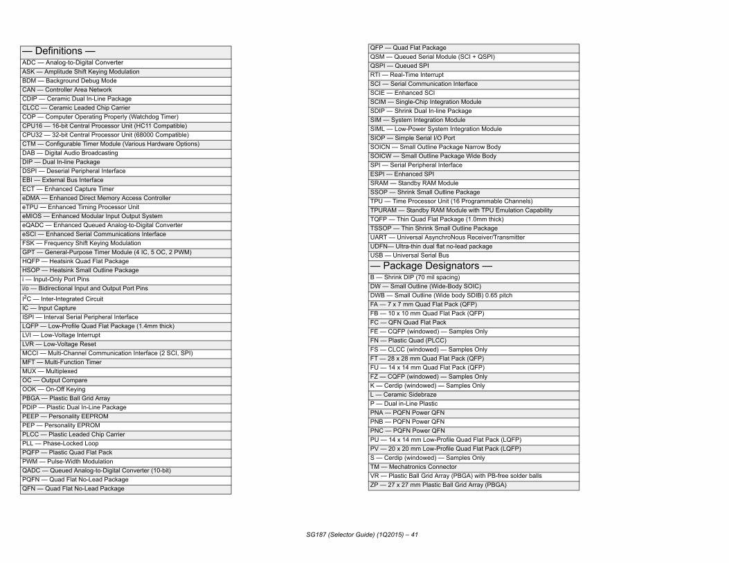
— DADC ASK BDMCAN CDIPCLCCCOP CPU1CPU3CTM DAB DIP —DSPIEBI —ECT eDMAeTPUeMIOeQADeSCIFSK GPT HQFPHSOPi — Ini/o —
I2C —IC —ISPI —LQFPLVI —LVR —MCCMFT MUXOC —OOKPBGAPDIPPEEPPEP PLCCPLL —PQFPPWMQADCPQFNQFN
)apability
alls
SG187 (Selector Guide) (1Q2015) – 41
efinitions —— Analog-to-Digital Converter— Amplitude Shift Keying Modulation — Background Debug Mode— Controller Area Network — Ceramic Dual In-Line Package — Ceramic Leaded Chip Carrier— Computer Operating Properly (Watchdog Timer)6 — 16-bit Central Processor Unit (HC11 Compatible)2 — 32-bit Central Processor Unit (68000 Compatible)— Configurable Timer Module (Various Hardware Options)— Digital Audio Broadcasting
Dual In-line Package — Deserial Peripheral Interface External Bus Interface
— Enhanced Capture Timer — Enhanced Direct Memory Access Controller — Enhanced Timing Processor UnitS — Enhanced Modular Input Output SystemC — Enhanced Queued Analog-to-Digital Converter
— Enhanced Serial Communications Interface— Frequency Shift Keying Modulation— General-Purpose Timer Module (4 IC, 5 OC, 2 PWM) — Heatsink Quad Flat Package — Heatsink Small Outline Packageput-Only Port Pins
Bidirectional Input and Output Port Pins
Inter-Integrated Circuit Input Capture
Interval Serial Peripheral Interface — Low-Profile Quad Flat Package (1.4mm thick) Low-Voltage Interrupt Low-Voltage Reset
I — Multi-Channel Communication Interface (2 SCI, SPI)— Multi-Function Timer — Multiplexed Output Compare
— On-Off Keying — Plastic Ball Grid Array
— Plastic Dual In-Line Package — Personality EEPROM
— Personality EPROM — Plastic Leaded Chip Carrier Phase-Locked Loop
— Plastic Quad Flat Pack — Pulse-Width Modulation — Queued Analog-to-Digital Converter (10-bit) — Quad Flat No-Lead Package
— Quad Flat No-Lead Package
QFP — Quad Flat PackageQSM — Queued Serial Module (SCI + QSPI)QSPI — Queued SPIRTI — Real-Time InterruptSCI — Serial Communication InterfaceSCIE — Enhanced SCISCIM — Single-Chip Integration ModuleSDIP — Shrink Dual In-line PackageSIM — System Integration ModuleSIML — Low-Power System Integration Module SIOP — Simple Serial I/O PortSOICN — Small Outline Package Narrow BodySOICW — Small Outline Package Wide BodySPI — Serial Peripheral InterfaceESPI — Enhanced SPISRAM — Standby RAM ModuleSSOP — Shrink Small Outline PackageTPU — Time Processor Unit (16 Programmable ChannelsTPURAM — Standby RAM Module with TPU Emulation CTQFP — Thin Quad Flat Package (1.0mm thick)TSSOP — Thin Shrink Small Outline PackageUART — Universal AsynchroNous Receiver/TransmitterUDFN— Ultra-thin dual flat no-lead packageUSB — Universal Serial Bus
— Package Designators —B — Shrink DIP (70 mil spacing)DW — Small Outline (Wide-Body SOIC)DWB — Small Outline (Wide body SDIB) 0.65 pitchFA — 7 x 7 mm Quad Flat Pack (QFP)FB — 10 x 10 mm Quad Flat Pack (QFP)FC — QFN Quad Flat PackFE — CQFP (windowed) — Samples OnlyFN — Plastic Quad (PLCC)FS — CLCC (windowed) — Samples OnlyFT — 28 x 28 mm Quad Flat Pack (QFP)FU — 14 x 14 mm Quad Flat Pack (QFP)FZ — CQFP (windowed) — Samples OnlyK — Cerdip (windowed) — Samples OnlyL — Ceramic SidebrazeP — Dual in-Line PlasticPNA — PQFN Power QFNPNB — PQFN Power QFNPNC — PQFN Power QFNPU — 14 x 14 mm Low-Profile Quad Flat Pack (LQFP)PV — 20 x 20 mm Low-Profile Quad Flat Pack (LQFP)S — Cerdip (windowed) — Samples OnlyTM — Mechatronics ConnectorVR — Plastic Ball Grid Array (PBGA) with PB-free solder bZP — 27 x 27 mm Plastic Ball Grid Array (PBGA)

— Pb-AA — Pb-AB — Pb-AC — Pb-AE — Pb-AF — Pb-AG — Pb-AH — Pb-AI — Pb-fAJ — Pb-fAE — Pb-ED — Pb-EE — Pb-EF — Pb-EG — Pb-EH — Pb-EI — Pb-fEJ — Pb-fEK — Pb-EL — Pb-EN — Pb-EO — Pb-EP — Pb-ER — Pb-ES — Pb-ET — Pb-EU — Pb-EV — Pb-FC — Pb-FE — Pb-VK — Pb-VL — Pb-VM — Pb-VN — Pb-VO — Pb-VP — Pb-VR — Pb-VS — Pb-VT — Pb-VU — Pb-VV — Pb-VW — PbVX — Pb-VY — Pb-
SG187 (Selector Guide) (1Q2015) – 42
free —free 44 to 100 pin QFPfree 112 to 288 pin QFPfree 16 to 44 pin LQFPfree 48 to 64 pin LQFPfree 68 to 100 pin LQFPfree 108 to 144 pin LQFbfree 80 to 100 pin TQFPree FQFPree CQFPfree 22 to 64 pin PDIPfree 6 yo 20 pin PDIPfree PSDIPfree 8 to 16 in SOICfree 16 to 28 pin SOIC WIDEfree 132 pin PQFPree PLCCree 8 to 24 pin TSSOPfree 32 to 54 pin SOIC WIDEfree 26 to 56 pin TSSOPfree 8 to 24 pin SSOPfree 26 to 56 pin SSOPfree QFN & MLF (Exposed Pad)free CATVfree SENSORfree RF (POWER CHIPS)free MAC PAACfree MFP (SOEIAJ)free QFN & MLF (Regular)free CerQuadsfree MAPBGA <=1.3mm (THINMAP) <.7mm Pitchfree MAPBGA <=1.3mm (THINMAP) >.7mm Pitchfree MAPBGA 1.6mm > .7mm Pitchfree MAPBGA 1.6mm < .7mm Pitchfree MAPBGA 1.35mm < .7mm Pitchfree MAPBGA 1.36mm > .7mm Pitchfree PBGAfree FC-HiTCE LGA (without C5 sphere)free FC PBGAfree FC-HiTCEfree TBGA-free HSOPfree SMTfree UNIBODY

P
SG187 (Selector Guide) (1Q2015) – 43
roduct Numbering System for MC56F8300 Digital Signal Controllers
MC 56F83 XX M XX 60
QUALIFICATION STATUSPC PRE-QUALIFICATION,
ENGINEERING SAMPLESMC FULLY QUALIFIED
AUTOMOTIVE CONTROLLERPRODUCT DESIGNATOR V -40C TO 105C
M -40C TO 125C
TEMPERATURE RANGE
PACKAGE TYPE
BUS SPEED
SERIES WITH FLASH

Pro
MSP,
SHIPPING METHODNONET1U
TRAYSTAPE AND REELRAILPTION
FACTORY
Y
PORTING STYLE
CP
SSX
AXIAL PORT (SMALL OUTLINE PACKAGE)PORTED (UNIBODY)
P SINGLE PORTDp DIFFERENTIAL PORT
STOVEPIPE PORT (UNIBODY)AXIAL PORT (UNIBODY)ROBUST AXIAL PORTW
GE
FPBGA
ED
TRA PACKAGEGNATORS
P
SG187 (Selector Guide) (1Q2015) – 44
duct Numbering System for Pressure SensorsM PX A 2 XXX A P X T1
PRODUCT CATEGORYQUALIFIED STANDARDCUSTOM PRODUCTPROTOTYPE PRODUCT
PRESSURE SENSORS
PACKAGING TYPENONEA/VAZ/VZ
UNIBODYSMALL OUTLINE PACKAGESMALL OUTLINE
X
PRODUCT FEATURES
LEADFORM O01–23–56–7
OPENCONSULTOPENSOP* ONL
MAXIMUM PRESSURE IN kPaEXCEPT FOR MPX2300EXPRESSED IN mmHg
PRODUCT TYPEAGD
ABSOLUTEGAUGEDIFFERENTIAL
MEDIA RESISTANT PACKAGEH SUPER SMALL OUTLINE PACKAGE
VACUUM/GAUGEV
M M-PAKSUPER SMALL OUTLINE PACKAGE (TPM)Y
5
678
NONE234
UNCOMPENSATEDTEMPERATURE COMPENSATED/CALIBRATEDOPENTEMPERATURE COMPENSATED/CALIBRATED/
SIGNAL CONDITIONED AUTOMOTIVE ACCURACY
TEMPERATURE COMPENSATED/CALIBRATED/ SIGNAL CONDITIONED
HIGH TEMPERATUREPOSITIVE/NEGATIVE PRESSURECMOS
HZ SUPER SMALL OUTLINEMEDIA RESISTANT PACKAGE
MAC 7 1 x x C FV 50 xx
STATUS OF PRODUCT:MAC FULLY QUALIFIEDSAC FULLY QUALIFIED AVAIL
FOR AUTO CUSTOMERSPAC PRODUCT ENGINEERING
CORE
PINOUT/PACKAGEOPTION DESIGNATOR
GENERATION (FAMILY)
SEQUENTIAL DEVICENUMBER
C -40 C TO 85 CV -40C TO 105 CM -40 C TO 125 C
TEMPERATURE RAN
U 100 LQFPV 112/144 LQF 208 MAP
AKAGE TYPE
BUS SPE
EXEI
roduct Numbering System for ARM Devices

PP RR
PACKAGING
TAPE AND REELDESIGNATOR
INDICATOR
SG187 (Selector Guide) (1Q2015) – 45
Product Numbering — Analog Auto and Power Management Devices
Legacy product numbering is available in ANALOGPN on www.freescale.com
SCPC
mm
33 - Automotive 34 - Industrial
xxxx v
32 - Consumer
35 - Medical/Military
FF
0000(default blank)
- Qualified Standard- Custom Device- Prototype Device
rMC
MCPRODUCT CATEGORY
MARKET
FAMILY/ROADMAP
CORE
SILICON REVISION
VARIATION(Defined by BU)
(default blank)
CM - Communication
BC - Battery Chargers
MM - Millimeter wave
PF - Power FusionSA - Safety AirbagSB - Safety BrakingVR - Voltage RegulatorXS - eXtreme switch
FS - System Basis Chips
CD - Configurable Detection
HB - H-Bridge
AR - Alternator Regulators
GD - Gate Drivers
BM - Battery Management
MR - MMIC Radar

C TO +85C
G METHOD
E OPTION
ATURE OPTIONS
T REVISION
CTURING SITE
TRAYE AND REEL
C TO +105CC TO +125C TO +140C
C TO +150C
C TO +85C
G METHOD
E OPTION
ATURE OPTIONS
CT REVISIONACTURING SITE
= TRAYE AND REEL
C TO +105CC TO +125C TO +140C
ant for the prior generations.
ant for the prior generations.
SG187 (Selector Guide) (1Q2015) – 46
S
QUALIFICATION STATUSPC = ENGINEERING SAMPLES
C = -40
8-Bit Automotive Microcontroller Part Numbering System* 9
S
S = AUTOMOTIVE QUALIFIEDMC = GENERAL MARKET QUALIFIEDSC = CUSTOM BUILD
MEMORY TYPE9 = FLASH3 = ROM (IF AVAILABLE)
S08
CORE
SL
DEVICE FAMILY
FLASH SIZE
SHIPPIN
PACKAG
TEMPER
PRODUC
MANUFA
S 9 S08 DZ16
128FF
1 M TJLFM2
BLANK =R = TAP
V = -40M = -40J = -40CW = -40
S
QUALIFICATION STATUSPC = ENGINEERING SAMPLES
C = -40
16-Bit Automotive Microcontroller Part Numbering System* 9
R
S = AUTOMOTIVE QUALIFIEDMC = GENERAL MARKET QUALIFIEDSC = CUSTOM BUILD
MEMORY TYPE9 = FLASH3 = ROM (IF AVAILABLE)
S12
CORE
HZ
DEVICE FAMILYFLASH SIZE
SHIPPIN
PACKAG
TEMPER
PRODUMANUF
S 9 S12 EG256128
JJ
3 C ALAAC2
BLANK R = TAP
V = -40M = -40J = -40C
EXAMPLES:
EXAMPLES:
*NOTE: Freescale’s automotive part numbering system has evolved over time, so the decoder scheme shown above may not be relev
*NOTE: Freescale’s automotive part numbering system has evolved over time, so the decoder scheme shown above may not be relev

*
IONS
*
NS
prior generations.
prior generations.
SG187 (Selector Guide) (1Q2015) – 47
M
QUALIFICATION STATUSPC = ENGINEERING SAMPLES
A = -55C TO +125C
32-Bit Automotive Microcontroller Part Numbering System for Qorivva 55xx Devices
PCR
S = AUTOMOTIVEMC = GENERAL MARKET QUALIFIED
POWER ARCHITECTURE CORE
PRODUCT NAME
5554
RESERVED/OPTIONAL FIELD
SHIPPING METHOD
PACKAGE OPTION
TEMPERATURE OPT
BUS SPEED
S PC 5514E AMC
13248
BLANK = TRAYR = TAPE AND REEL
C = -40C TO +85CV = -40C TO +105CM = -40C TO +125C
VRLQ
P
QUALIFICATION STATUSPC = ENGINEERING SAMPLES
32-Bit Automotive Microcontroller Part Numbering System for Qorivva 56xx Devices
PCR
S = AUTOMOTIVEMC = GENERAL MARKET QUALIFIED
POWER ARCHITECTURE CORE
PRODUCT NAME
5604B
RESERVED/OPTIONAL FIELD
SHIPPING METHOD
PACKAGE OPTION
TEMPERATURE OPTIO
S PC 5604SE M
M
BLANK = TRAYR = TAPE AND REEL
C = -40C TO +85CV = -40C TO +105CM = -40C TO +125C
VRLQE
*NOTE: Freescale’s automotive part numbering system has evolved over time, so the decoder scheme shown above may not be relevant for the
EXAMPLES:
EXAMPLES:
*NOTE: Freescale’s automotive part numbering system has evolved over time, so the decoder scheme shown above may not be relevant for the
How to Reach Us:
Home Page:www.freescale.com
Web Support:http://www.freescale.com/support
For current information, please visit freescale.com/analog
Freescale and the Freescale logo are trademarks of Freescale Semiconductor, Inc., Reg. U.S. Pat. & Tm. Off. SMARTMOS is a trademark of Freescale Semiconductor, Inc.
All other product or service names are the property of their respective owners.
© 2015 Freescale Semiconductor, Inc.
SG187 Q1 2015, Rev 573/2015