automotive seals self-study guide · automotive seals self-study guide expanding your knowledge of...
TRANSCRIPT
Automotive Seals Self-Study Guide Expanding your knowledge of seals and related components
TABLE OF CONTENTSIntroduction . . . . . . . . . . . . . . . . . . . . . . 4
Chapter 1: The Shaft Seal. . . . . . . . . . . . 6Seal/Components . . . . . . . . . . . . . . . . . . . . . 8How the Seal Works . . . . . . . . . . . . . . . . . . . 8Review. . . . . . . . . . . . . . . . . . . . . . . . . . . . . 10
Chapter 2: Sealing Element (Lip) Materials . . . . . . . . . . . . . . . . . . . . . . . 12Synthetics . . . . . . . . . . . . . . . . . . . . . . . . . 12Non-Synthetics . . . . . . . . . . . . . . . . . . . . . 16The Waveseal . . . . . . . . . . . . . . . . . . . . . . 18Review . . . . . . . . . . . . . . . . . . . . . . . . . . . . 19
Chapter 3: Seal Selection . . . . . . . . . . . 21Replacement Seals . . . . . . . . . . . . . . . . . . 21Seal Substitutions . . . . . . . . . . . . . . . . . . . 21Seals for New Applications . . . . . . . . . . . . 22Measuring Seal Size . . . . . . . . . . . . . . . . . 23Pressure/Temperature/Fluid Compatibility . . 24Review . . . . . . . . . . . . . . . . . . . . . . . . . . . . 25
Chapter 4: Pre-Installation Requirements . . . . . . . . . . . . . . . . . . . 27Shaft Requirements . . . . . . . . . . . . . . . . . 27Bore Requirements . . . . . . . . . . . . . . . . . . 30Pre-Lubrication . . . . . . . . . . . . . . . . . . . . . 32Tools . . . . . . . . . . . . . . . . . . . . . . . . . . . . . . 32Review . . . . . . . . . . . . . . . . . . . . . . . . . . . . 35
Chapter 5: Grease Seal Installation . . . 37Front Axle . . . . . . . . . . . . . . . . . . . . . . . . . . 37Installation Checklist . . . . . . . . . . . . . . . . . 39Drive Axle . . . . . . . . . . . . . . . . . . . . . . . . . 40Review . . . . . . . . . . . . . . . . . . . . . . . . . . . . 42
Chapter 6: Troubleshooting . . . . . . . . . 44Preliminary Survey . . . . . . . . . . . . . . . . . . 44Seal Markings/Cocked Seal . . . . . . . . . . . . 44Operating Temperature/Excessive Pressure . 45Incorrect Lubricant . . . . . . . . . . . . . . . . . . 46Review . . . . . . . . . . . . . . . . . . . . . . . . . . . . 47
Chapter 7: Wear Sleeves . . . . . . . . . . . 49Speedi-Sleeves . . . . . . . . . . . . . . . . . . . . . 49Speedi-Sleeve Installation . . . . . . . . . . . . . 50Review . . . . . . . . . . . . . . . . . . . . . . . . . . . . 52
Chapter 8: Rear Wheel Seal and PinionInstallation . . . . . . . . . . . . . . . . . . . . . . 54Bearing/Seal Removal . . . . . . . . . . . . . . . . 54Bearing/Seal Installation . . . . . . . . . . . . . . 55Pinion Seal Replacement . . . . . . . . . . . . . . 57Review. . . . . . . . . . . . . . . . . . . . . . . . . . . . . 60
4
INTRODUCTIONThis book, produced for use by SKF distributors and
customers, should prove of practical value to engineers, fleetmechanics, maintenance superintendents and anyone who canbenefit from a thorough understanding of seals. It will explain:
• How to select the best seal for any given application;• How to improve performance with proper installation;• How to spot–—and correct—seal problems withthe least possible amount of time and money.
How to Use this Study GuideThis self-study guide is programmed to increase performance
productivity. Each chapter consists of a logical organization ofmaterial, technical diagrams and a short quiz to help you retainwhat you study.
Start by carefully reading the text portion of each chapter.Make notes or underline if you wish; this can help you remember what you’ve read.
It does not matter whether you are a fast or slow learner. At the end of the program, you will have learned the sameinformation—and should retain it—as well as any other“student.”
The chapter quizzes are an important phase in self-studylearning since they are intended to reinforce the material covered. The quiz questions are straightforward multiple choiceand true-false. There are no “trick questions.” Your answers caneasily be checked within the context of the chapter.
Complete each review in order before going on to the nextchapter. If you are not sure of an answer to a question, checkback in the chapter and review that portion again.
5
Brief History of the Shaft SealSKF invented and patented the first integrated shaft seal in
1928. It was designed to hold grease in automobile wheelbearings.
In the mid 1930’s, SKF pioneered the development of customformulating, compounding and molding elastomers (syntheticrubber). This led to other innovations in manufacturingprocesses, new sealing techniques, and the compounding andmolding of various elastomer seals.
Today, SKF is the world’s leading supplier of fluid sealingdevices for the truck, automotive, farm equipment, aircraft,heavy machinery and machine tool industries.
SKF also supplies seals for aerospace missiles, earthmovingequipment, appliances, and a wide variety of pumps, hydraulicsystems, motors and subassemblies.
SKF can supply more than 200 types of seals in more than3,000 stock sizes. That includes seals in both bonded and assembled designs, with single or double lip elements, and with or without spring-loading or inner cases.
SKF seals fit shaft diameters from .188" to over 180". All arefashioned from a large and ever-growing spectrum of sealingelements and case materials.
6
THE SHAFT SEALIn this world of moving parts, whenever a shaft rotates,
it needs a bearing for smooth, effective operation.
In most cases, where there’s a bearing, you’ll find a seal helping it to do its job better. In simple terms, a shaft seal is a barrier.
Shaft seals are designed to:• Retain lubricants or liquids• Confine pressure• Exclude dirt• Separate fluids
Seals are necessary for sealing in lubricants that are needed to protect the bearings and to seal out dirt, waterand contaminants. To do both jobs effectively, all seals demandprecise engineering and manufacturing.
Seal designs and materials are constantly being developed,tested and improved. This testing is being done to conform withtoday’s increased performance and durability requirements.
The material being sealed can be anything from light oil toheavy grease, or even hot turbine gases. Wheel seals areamong the most common applications. The seal retains lube inthe bearing, and at the same time, protects the bearing from contaminants such as water, dirt, dust and abrasives.
First, it must be decided which is more important: retentionof lubricant, exclusion of foreign matter or, in some cases, both.
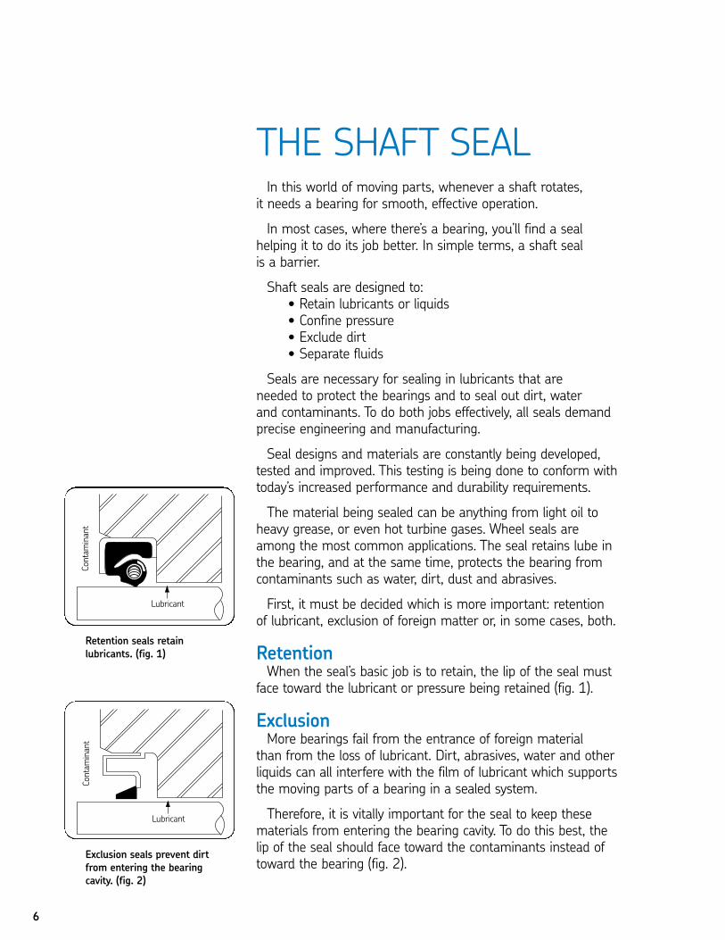
RetentionWhen the seal’s basic job is to retain, the lip of the seal must
face toward the lubricant or pressure being retained (fig. 1).
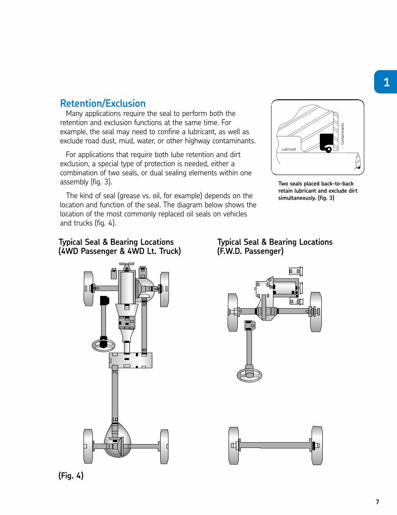
ExclusionMore bearings fail from the entrance of foreign material
than from the loss of lubricant. Dirt, abrasives, water and otherliquids can all interfere with the film of lubricant which supportsthe moving parts of a bearing in a sealed system.
Therefore, it is vitally important for the seal to keep these materials from entering the bearing cavity. To do this best, the lip of the seal should face toward the contaminants instead oftoward the bearing (fig. 2).
Retention seals retain lubricants. (fig. 1)
Exclusion seals prevent dirtfrom entering the bearingcavity. (fig. 2)
7
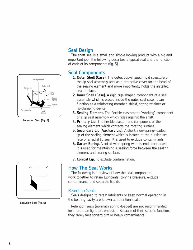
Retention/ExclusionMany applications require the seal to perform both the
retention and exclusion functions at the same time. Forexample, the seal may need to confine a lubricant, as well asexclude road dust, mud, water, or other highway contaminants.
For applications that require both lube retention and dirtexclusion, a special type of protection is needed, either a combination of two seals, or dual sealing elements within oneassembly (fig. 3).
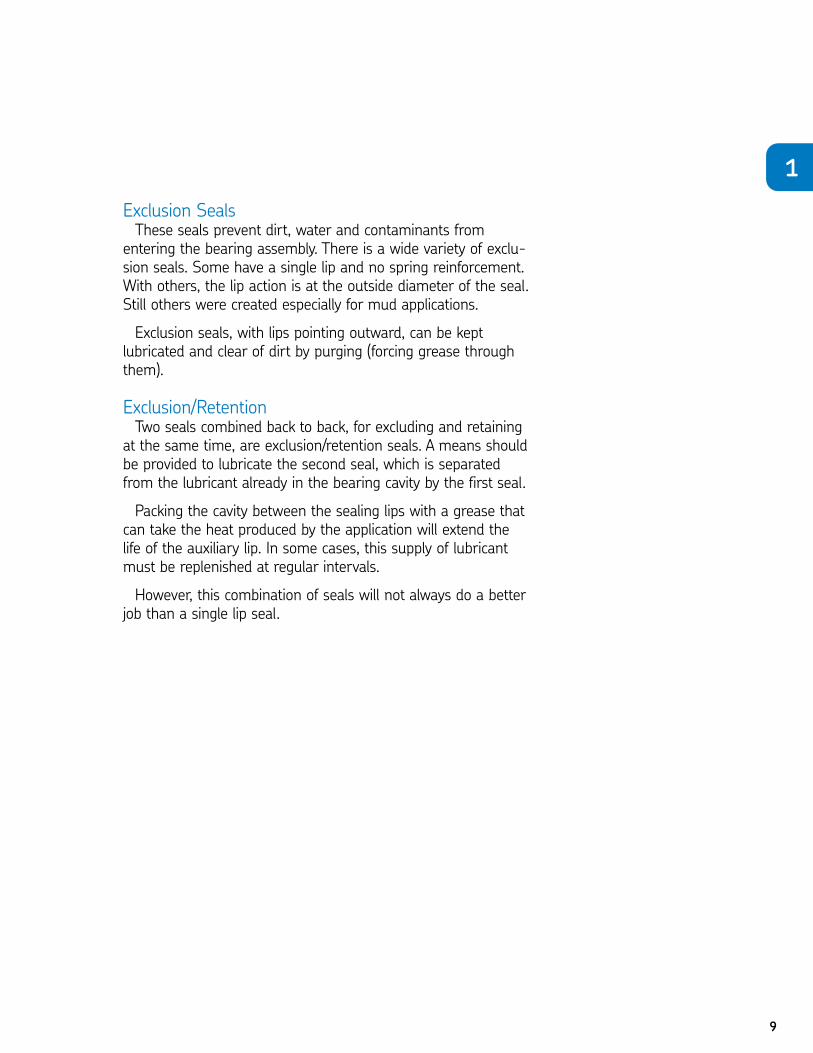
The kind of seal (grease vs. oil, for example) depends on thelocation and function of the seal. The diagram below shows thelocation of the most commonly replaced oil seals on vehiclesand trucks (fig. 4).
Two seals placed back-to-backretain lubricant and exclude dirtsimultaneously. (fig. 3)
1
Typical Seal & Bearing Locations(4WD Passenger & 4WD Lt. Truck)
Typical Seal & Bearing Locations(F.W.D. Passenger)
(Fig. 4)
8
Seal DesignThe shaft seal is a small and simple looking product with a big and
important job. The following describes a typical seal and the functionof each of its components (fig. 5).
Seal Components1. Outer Shell (Case). The outer, cup-shaped, rigid structure ofthe lip seal assembly acts as a protective cover for the head ofthe sealing element and more importantly holds the installedseal in place.
2. Inner Shell (Case). A rigid cup-shaped component of a sealassembly which is placed inside the outer seal case. It can function as a reinforcing member, shield, spring retainer orlip-clamping device.
3. Sealing Element. The flexible elastomeric “working” componentof a lip seal assembly which rides against the shaft.
4. Primary Lip. The flexible elastomeric component of the sealing element which contacts the rotating surface.
5. Secondary Lip (Auxiliary Lip). A short, non-spring-loaded lip of the sealing element which is located at the outside sealface of a radial lip seal. It is used to exclude contaminants.
6. Garter Spring. A coiled wire spring with its ends connected. It is used for maintaining a sealing force between the sealingelement and sealing surface.
7. Conical Lip. To exclude contamination.
How The Seal WorksThe following is a review of how the seal components
work together to retain lubricants, confine pressure, exclude contaminants and separate liquids.
Retention SealsSeals designed to retain lubricants or keep normal operating in
the bearing cavity are known as retention seals.
Retention seals (normally spring-loaded) are not recommended for more than light dirt exclusion. Because of their specific function,they rarely face toward dirt or heavy contaminants.
Retention Seal (fig. 5)
Exclusion Seal (fig. 6)
9
Exclusion SealsThese seals prevent dirt, water and contaminants from
entering the bearing assembly. There is a wide variety of exclu-sion seals. Some have a single lip and no spring reinforcement.With others, the lip action is at the outside diameter of the seal.Still others were created especially for mud applications.
Exclusion seals, with lips pointing outward, can be keptlubricated and clear of dirt by purging (forcing grease throughthem).
Exclusion/RetentionTwo seals combined back to back, for excluding and retaining
at the same time, are exclusion/retention seals. A means shouldbe provided to lubricate the second seal, which is separatedfrom the lubricant already in the bearing cavity by the first seal.
Packing the cavity between the sealing lips with a grease thatcan take the heat produced by the application will extend thelife of the auxiliary lip. In some cases, this supply of lubricantmust be replenished at regular intervals.
However, this combination of seals will not always do a betterjob than a single lip seal.
1
To take this test simply place a card or sheet of paper under the first question.After you’ve read it (and answered it to yourself), slide the paper down below the next question. The correct answer to the first problem will appear directly tothe right of the new question. Be sure not to skip any of the questions. This learning technique assures more than four times the normal retention rate foreven this technical subject.
01. A shaft seal is a barrier designed to .N a. retain lubricants or liquids and exclude dirtN b. confine pressure N c. separate fluids N d. all of the above
1. D
02. Packing the cavity between the sealing lips of exclusion/retention seals with a grease that can take the heat produced by the application will
.N a. shorten the life of the auxiliary lipN b. extend the life of the auxiliary lipN c. damage both lipsN d. none of the above
2. B
03. A typical vehicle may require .N a. steering sealsN b. transmission rear sealsN c. front crank sealsN d. all of the above
3. D
04. Another name for the outer shell of the seal is the outer .N a. lipN b. caseN c. coneN d. spring
4. B
05. Bearings fail more from than from the loss of lubricants.N a. the entrance of foreign materialN b. improper seal installationN c. the retention of lubricantN d. all of the above
5. A
10
CHAPTER 1 REVIEW
11
06. Exclusion seals can be kept lubricated and clear of dirt by .N a. regular cleaning N b. a second seal N c. a special sealing material N d. purging grease through the lips
6. D07. Every rotating shaft requires a bearing and a seal for smooth,
effective operation.N True N False
7. T08. A shaft seal is a barrier designed only to confine pressure.
N True N False8. F
09. Seals are needed to seal in lubricants necessary for the bearings, and to seal out dirt, water, and contaminants.
N True N False9. T
10. If the seal’s basic job is to retain lubricants or liquid, the seal lip must face toward the lubricant or pressure being retained.
N True N False10. T
11. If the seal’s basic job is to exclude contaminants, the lip of the seal should face toward the bearing, instead of toward the contaminants.
N True N False11. F
12. Spring-loaded seals designed to retain lubricants or keep pressure in the bearing cavity are known as exclusion seals.
N True N False12. F
13. Retention seals stop dirt, water, and contaminants from entering the bearing cavity.
N True N False13. F
14. Seal components include an outer shell, inner shell, sealing element, sealing lip and garter spring.
N True N False14. T
15. Two seals may never be combined within the same assembly.N True N False
15. F
1
12
SEALING ELEMENT(LIP) MATERIALSSKF seals have a synthetic lip material bonded to the metal
shell (case). The bonding prevents leakage between the sealinglip and the shell, and it provides a longer lasting, more effectiveseal. This is different from the process used for assembledseals, in which assembly pressure is used to hold the lip inplace between the metal parts.
A wide variety of sealing element (lip) materials is available.Each has its own unique characteristics. Selection should bemade on the basis of application, compatibility with lubricantsand fluids being retained, operating temperatures, and otherconditions.
SyntheticsToday, the most popular and widely used sealing materials
are synthetics. These include nitriles, polyacrylates, silicones and fluoroelastomers. Each material has its own advantages and disadvantages.
Nitrile Nitrile is the most popular material for the major applications
today. It is actually a mixture of two basic synthetic rubbers,Buna and acrylonitrile polymers. Different properties areobtained by changing the percentage of each polymer used in the mixture (or copolymer).
Nitrile has generally replaced leather as a sealing lip material.
ADVANTAGES+ Good oil/grease compatibility+ Abrasion resistance+ Good low temperature and swell characteristics+ Good manufacturing qualities+ Relatively low in cost
DISADVANTAGES- Lacks compatibility with synthetic oils such as phosphateester and Skydrol
- Not recommended with EP lubes at elevated temperatures
OPERATING RANGEStandard SKF seals with nitrile sealing lips are effective in applications involving most mineral oils and greases in temperatures ranging from -65ºF to 250ºF.
13
IDENTIFICATIONVaries from gray-black to shiny jet black
SUBSTITUTE LIP MATERIALSPolyacrylate, silicone or fluoroelastomer (See SealSubstitutions, page 21).
DuralipDuralip is SKF’s special nitrile compound for extreme abrasion
resistance. It is recommended where scale, sand, grit, dirt orother highly abrasive materials are present.
ADVANTAGES+ Extreme abrasion resistance+ See nitrile
DISADVANTAGESSee nitrile
OPERATING RANGESee nitrile
IDENTIFICATIONSee nitrile
SUBSTITUTE LIP MATERIALSSee nitrile
PolyacrylatesPolyacrylates are elastomers that are compatible with higher
operating temperatures, as well as extreme pressure (EP) lubricants. They are available in most general purpose designs.
ADVANTAGES+ Good compatibility with most oils, including EP lubricants+ High resistance to oxidation and ozone+ Better compatibility with higher operating temperaturesthan nitrile
DISADVANTAGES- Low compatibility with water and some industrial fluids- Poor compression-set characteristics
OPERATING RANGESeals with polyacrylate lips are effective in temperatures ranging from -40ºF to 300ºF.
2
14
IDENTIFICATIONGenerally black with same appearance as nitrile
SUBSTITUTE MATERIALS Nitrile, silicone or fluoroelastomer (See Seal Substitutions,page 21).
SiliconeSilicone’s high lubricant absorbency minimizes friction and
wear. It can be used in a wide range of temperatures. Siliconeseals are made only in bonded designs.
ADVANTAGES+ High lubricant absorbency+ Very flexible+ Wide temperature range
DISADVANTAGES- Poor compatibility with oils that have become oxidized, and EP lube additives
- Tendency to tear and cut during installation- Poor abrasion resistance- Relatively high cost
OPERATING RANGESilicone seals can withstand a very wide temperature range,from -100º to 325ºF.
IDENTIFICATION Generally red or orange, but sometimes gray or blue. Siliconeseals feel softer and are more flexible than other materials
SUBSTITUTE LIP MATERIALS Fluoroelastomers, polyacrylate or nitrile (See SealSubstitutions, page 21).
Fluoroelastomers (FKM)Fluoroelastomers are recommended for use with special
lubricants and chemicals which cannot be handled by nitrile,polyacrylate or silicone. They are compatible with oils, chemicals, fuels and lubricants over a broad range of temperatures that are too extreme for other sealing elements.
15
Fluoroelastomers are available in standard line designs as well as large diameter seals. One fluoroelastomer (FKM) is compatible with aliphatic and aromatic hydrocarbons (carbon tetrachlorine, benzene, toluene, xylene) that are used as solvents for other rubbers.
Because of its compatibility with many different fluids over a broad temperature range, FKM also is effective in aircraft and space equipment applications.
ADVANTAGES+ Wide temperature range+ Low swell characteristics+ Compatible with lubes, additives and chemicals that destroyother synthetic materials
+ Less downtime+ Extreme abrasion resistance
DISADVANTAGES- Relatively high cost
OPERATING RANGE-40ºF to 400ºF
IDENTIFICATIONBrown to black; may also be blue or green
SUBSTITUTE LIP MATERIALS(See Seal Substitutions, page 21).
Other SyntheticsIn addition to these standard materials, SKF can supply seals
with elements molded of other materials for special conditions.
2
16
Non-Synthetics
PTFESKF PTFE seals are assembled, made-to-order radial shaft
seals based on PTFE (polytetrafluoroethylene). This thermoplastic material offers a solution for designers and engineers faced with operating conditions that exceed the capabilities of rubber compounds.
PTFE offers wider media resistance in comparison to standard elastomers with a temperature range of -100˚ to500˚F (-73˚ to 260˚C). With the addition of appropriate fillers, PTFE has excellent mechanical properties, low frictionand wear resistance.
ADVANTAGES+ Superior tensile strength and abrasion resistance+ Performs well with little or no lubrication+ Tends to smooth rough shaft surfaces+ Compatible with lubes and solvents. Chemically invert.+ High speeds in excess of 15,000 fpm
DISADVANTAGES- Can be abrasive- Installation tool required- Expensive
OPERATING RANGEPTFE can handle temperatures ranging from -100ºF to 500º F.
IDENTIFICATIONPTFE is easily identified by its thin wafer appearance with a plastic “feed” to it.
SUBSTITUTE LIP MATERIALFluoroelastomer (See Seal Substitutions, page 21).
FeltFelt is another non-synthetic material which has long been
used as a sealing material. Made of wool and sometimes laminated with synthetic rubber washers, felt is generally limited to light dirt exclusion. However, it effectively retains
17
heavy lubricants such as wheel bearing grease and performswell in sparsely lubricated applications under some conditionssuch as small electric motors. Felt washers are available only in limited sizes.
ADVANTAGES+ Excludes dirt and dust well+ Retains grease efficiently+ High lubricant absorbency
DISADVANTAGES- Cannot confine light oils- May trap metal particles, causing shaft wear- Absorbs water, which may cause shaft rusting
OPERATING RANGE-65ºF to 200ºF
SUBSTITUTE LIP MATERIALSNitrile, polyacrylate or fluoroelastomer (See SealSubstitutions, page 21).
Compound Selection ChartThe compatibility of sealing element materials with most
fluids currently used can be found in the Compound SelectionChart in the SKF Handbook of Seals (Catalog #457010).
This chart rates the operation of different sealing materials(minor effect, moderate effect, static only, not recommended,insufficient data) within the range of specified operating temperatures and conditions for most common lubricants, fresh or salt water, and fluids.
Sealing Lip PerformanceFollowing is a description of the lip itself and how it works.
In this example, the Waveseal will be used. The Waveseal, SKF’s preferred design, provides at least 30% more service lifethan other radial lip seals. A number of the toughest fleetapplications specify this design to assure top performance and increased service life.
2
18
Waveseals®The SKF Waveseal features a sealing process utilizing
hydrodynamics, that is completely different from that of conventional seals.
In technical terms, the Waveseal is a smooth lip, birotationalhydrodynamic radial lip seal. More simply, it is a shaft seal that pumps lubricant back into the sump while sealing outcontaminants—no matter which way the shaft is turning.
In terms of shaft and seal wear, the SKF Waveseal is important to truck operators because:• It offers more dependable performance and up to 30%longer service life than conventional seals.
• Its design has almost universal fleet applications.• It is the first standard line of shaft seals utilizinghydrodynamics.
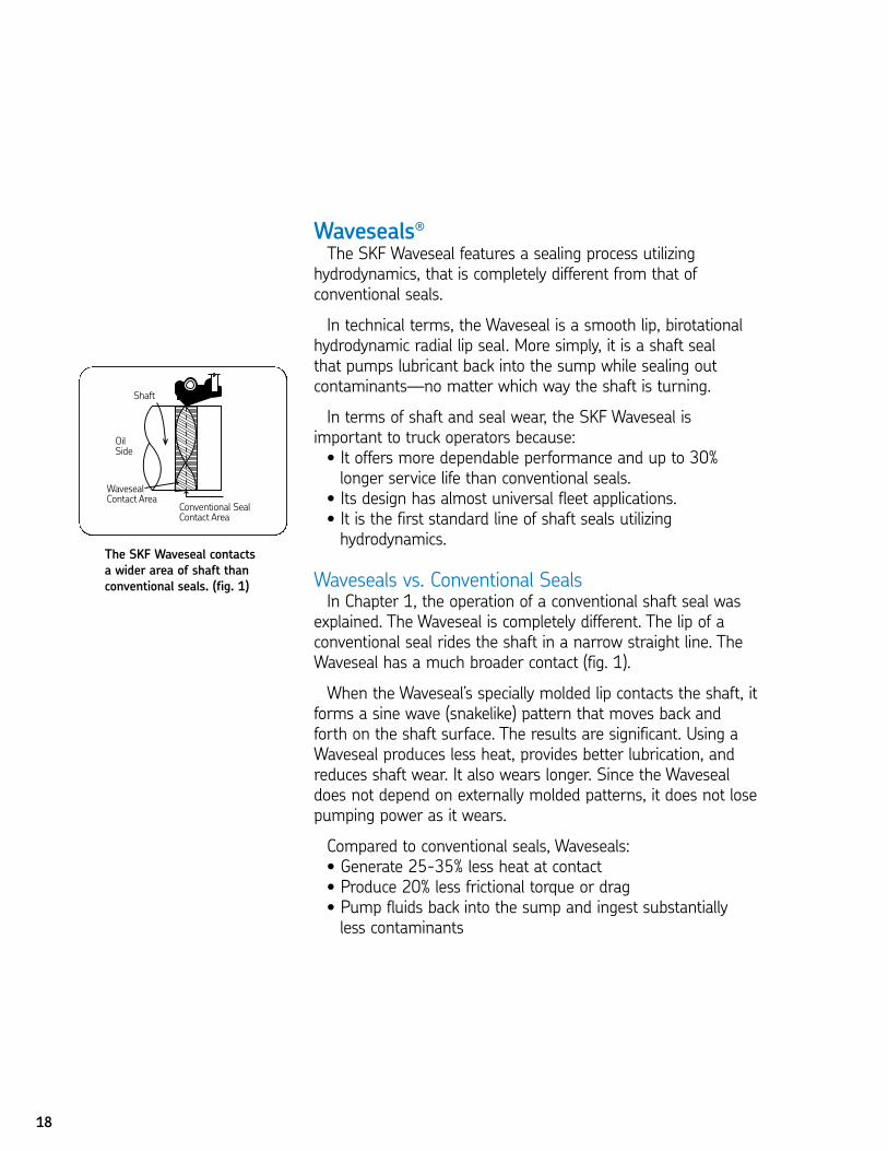
Waveseals vs. Conventional SealsIn Chapter 1, the operation of a conventional shaft seal was
explained. The Waveseal is completely different. The lip of aconventional seal rides the shaft in a narrow straight line. TheWaveseal has a much broader contact (fig. 1).
When the Waveseal’s specially molded lip contacts the shaft, itforms a sine wave (snakelike) pattern that moves back andforth on the shaft surface. The results are significant. Using aWaveseal produces less heat, provides better lubrication, andreduces shaft wear. It also wears longer. Since the Wavesealdoes not depend on externally molded patterns, it does not losepumping power as it wears.
Compared to conventional seals, Waveseals:• Generate 25-35% less heat at contact• Produce 20% less frictional torque or drag• Pump fluids back into the sump and ingest substantiallyless contaminants
The SKF Waveseal contactsa wider area of shaft thanconventional seals. (fig. 1)
19
CHAPTER 2 REVIEWTo take this test simply place a card or sheet of paper under the first question.
After you’ve read it (and answered it to yourself), slide the paper down below thenext question. The correct answer to the first problem will appear directly to theright of the new question. Be sure not to skip any of the questions. This learningtechnique assures more than four times the normal retention rate for even thistechnical subject.
01. SKF seals are available in a wide variety of sealing element materials and eachhas its own unique characteristics. Selection should be on the basis of .
N a. application N b. compatibility with lubes and fluids N c. operating temperature N d. all of the above
1. D02. Nitrile has generally replaced as a sealing lip.
N a. felt N b. silicone N c. leather N d. fluoroelastomer (FKM)
2. C03. One of nitrile’s disadvantages is that it is not compatible with .
N a. oilN b. abrasionN c. synthetic oilsN d. all of the above
3. C04. One of polyacrylate’s disadvantages is its .
N a. low compatibility with water and some industrial fluidsN b. high resistance to oxidation and ozoneN c. relatively high costN d. good compression-set characteristics
4. A05. PTFE (polytetrafluoroethylene)
N a. is toughN b. resists chemicalsN c. can be used in high temperature applications N d. all of the above
5. D06. Silicone’s advantages include its .
N a. high lube absorbencyN b. good flexibilityN c. ability to handle a wide temperature rangeN d. all of the above
6. D
2
07. Seals made of fluoroelastomers .N a. are inexpensive N b. sometimes require special molds N c. lack wide temperature range resistance N d. are compatible with oil
7. D08. Felt is a non-synthetic material which has long been used as a
sealing material. Its advantages include .N a. excellent water resistanceN b. good exclusion of dust and dirtN c. tends to smooth rough shaft surfacesN d. good oil retention
8. B09. Using a Waveseal produces significant results which include .
N a. less heat producedN b. less shaft wearN c. better lip lubricationN d. all of the above
9. D10. The most popular and versatile sealing materials in use today are
synthetics, such as nitrile, polyacrylates, silicones and fluoroelastomers.N True N False
10. T11. Nitrite is the most popular material for the majority of sealing
applications today.N True N False
11. T12. One of fluoroelastomer's disadvantages is its poor resistance to temperature extremes.
N True N False12. F
13. Polyacrylates are elastomers that work well with high operatingtemperatures and EP lubricants.
N True N False13. T
14. Polyacrylates have high resistance to water.N True N False
14. F15. The lip of a Waveseal rides the shaft in a straight-line pattern.
N True N False15. F
20
21
SEAL SELECTION Other than faulty installation, the most common reason a seal
fails is that it is not the correct seal for the application. It is veryimportant to check the old seal and replace it with one that iscorrect for the application.
Replacement SealsIf the old seal being replaced was manufactured by SKF, it
should have one of four identifying numbers:1. an SKF stock number2. an older SKF part number3. an SKF drawing number4. the original equipment manufacturer’s part number
The SKF Master Interchange (Catalog #457012) lists the SKFstock numbers that correspond to nearly 150,000 shaft seals in use today.
The simplest method of replacement is to use the numberof the old seal. If this number is unreadable or unavailable, areplacement can be selected by matching sizes with listings inthe SKF Handbook of Seals (Catalog #457010).
If there is no seal listed in exactly the same width, a narrowerwidth is usually the best choice. A wider width is perfectlyacceptable if space permits, however it is often limited.
Seal SubstitutionsThe SKF Handbook of Seals lists different seal designs which
can be substituted for the old seal (within the limits of theoperating conditions). Seal materials and proper substituteswere discussed in the previous chapter. Because of the importance of knowing and understanding these materials, they will be reviewed here.
If a lip material to match the old seal cannot be found in the size listings, refer to the Substitute Material Table in the Handbook of Seals. Some of the more common seal substitutions are listed below.
• Nitrile instead of felt• Nitrile instead of leather• Polyacrylate instead of nitrile• Fluoroelastomer instead of polyacrylate• Fluoroelastomer instead of silicone• Fluoroelastomer instead of PTFE
3

22
Remember, colors other than black usually mean specialmaterials. Materials should generally be substituted only ifimmediate replacement is more important than the assuranceof maximum seal life. Because of the great number of factorsinvolved, it is not always true that a premium elastomer will doa better sealing job than a less expensive material.
If the operating temperature is above 250ºF, nitrile seals substituted for polyacrylate or silicone may have a shorterlife. And, while silicone has a wider temperature range thanpolyacrylate, it breaks down if it is exposed to oxidized oils.
Seals For New ApplicationsChoosing the right seal for a particular application depends
on operating conditions:1. Size2. Speed3. Pressure 4. Temperature/Fluid compatibility
Each of these operating conditions should influence yourselection of a seal for that application.
SizeSeal dimensions (fig. 1) used in seal selection include:
Seal Bore DiameterThis is the diameter of the hole into which the seal will be
fitted.
Seal Outside Diameter (O.D.)The O.D. is the seal’s press-fit diameter. It is usually .004"
to .010" larger than the bore so the seal will be held firmly inplace.
Seal WidthThis is the overall width (including the inner and outer shells).
Shaft DiameterBecause the seal’s inside diameter is difficult to measure and
varies with seal designs, the shaft diameter for which the sealwas designed is used as the cataloged inside dimension.
(fig. 1)
23
Measuring the Seal O.D.When measuring the seal’s outside diameter, measurements
should be taken in at least three places equally spaced aroundthe seal. The average of these readings can then be used asthe diameter.
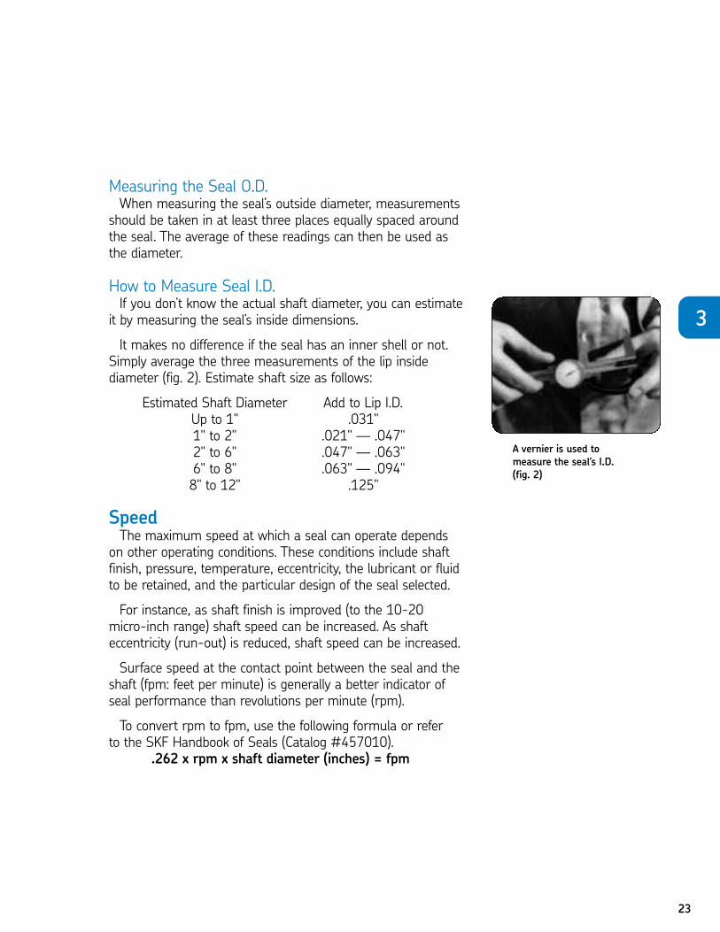
How to Measure Seal I.D.If you don’t know the actual shaft diameter, you can estimate
it by measuring the seal’s inside dimensions.
It makes no difference if the seal has an inner shell or not.Simply average the three measurements of the lip inside diameter (fig. 2). Estimate shaft size as follows:
Estimated Shaft Diameter Add to Lip I.D.Up to 1" .031" 1" to 2" .021" — .047"2" to 6" .047" — .063"6" to 8" .063" — .094"8" to 12" .125"
SpeedThe maximum speed at which a seal can operate depends
on other operating conditions. These conditions include shaftfinish, pressure, temperature, eccentricity, the lubricant or fluidto be retained, and the particular design of the seal selected.
For instance, as shaft finish is improved (to the 10-20 micro-inch range) shaft speed can be increased. As shafteccentricity (run-out) is reduced, shaft speed can be increased.
Surface speed at the contact point between the seal and theshaft (fpm: feet per minute) is generally a better indicator ofseal performance than revolutions per minute (rpm).
To convert rpm to fpm, use the following formula or referto the SKF Handbook of Seals (Catalog #457010).
.262 x rpm x shaft diameter (inches) = fpm
A vernier is used to measure the seal’s I.D. (fig. 2)
3
24
PressureThe next aspect important to proper seal selection is
pressure.
Allowable pressure goes down as shaft speed goes up.
The more pressure applied to a seal, the more lip surfacecontacts the shaft. More contact produces more friction andheat. Friction and heat rise as shaft speed increases. These factors cause faster wear and can shorten seal life.
Many of the bonded designs in the SKF Handbook of Sealscan handle pressures of 15 psi at speeds up to 1,000 fpm.These can be found in the Handbook’s table of operating conditions.
When speeds increase past 1,000 fpm, some of these sameseals can handle only 5 psi.
Temperature/Fluid CompatibilityThe final consideration affecting seal selection is temperature
and fluid compatibility. Handbook listings are given in 16 “continuous” ratings—the relatively constant ambienttemperature next to the seal, or the temperature of the lubricant it retains.
When operating conditions are under 0ºF or above 200ºF,the range recommended in the Handbook must be consideredin selecting the type of sealing element material.
As was earlier stated, SKF’s standard nitrile compound provides good service in most sealing applications from -65ºFto 250ºF. However, silicone, polyacrylate or fluoroelastomersprovide safer operating limits and are preferred with higheror lower temperatures.
SummaryThere are many factors involved in selecting seals. To
avoid confusion, the SKF Handbook of Seals contains aRecommended Operating Conditions Selection Chart to assure a correct seal choice.
All of the selection factors are grouped together along withrecommendations about the type of seal to use in almost everyapplication.
25
CHAPTER 3 REVIEWTo take this test simply place a card or sheet of paper under the first question.
After you’ve read it (and answered it to yourself), slide the paper down below thenext question. The correct answer to the first problem will appear directly to theright of the new question. Be sure not to skip any of the questions. This learningtechnique assures more than four times the normal retention rate for even thistechnical subject.
01. A replacement seal manufactured by SKF is identified by .N a. an SKF stock numberN b. an SKF drawing numberN c. the original equipment manufacturer’s part numberN d. any of the above
1. D
02. Choosing the right seal for an application depends on .N a. seal dimensionsN b. speed and pressureN c. temperatureN d. all of the above
2. D
03. A substitute material for silicone is .N a. feltN b. leatherN c. nitrileN d. none of the above
3. C
04. Nitrile seals will have shortened lifespans if the operatingtemperature is 250ºF.
N a. belowN b. aboveN c. atN d. none of the above
4. B
05. is the seal’s press-fit diameter; usually .004" to .008" larger than the bore.
N a. Shaft diameterN b. Seal outside diameterN c. Seal inside diameterN d. Bore diameter
5. B
3
06. The maximum speed at which a seal can operate depends on other operatingconditions. These conditions include .
N a. the design of the seal selectedN b. the lubricant or fluid to be retainedN c. pressure and temperatureN d. all of the above
6. D07. If the seal has no identification numbers, you should average
three measurements of the .N a. seal widthN b. seal boreN c. lip inside diameterN d. any of the above
7. C08. A common reason for seal failure is that it is not the right seal
for the application in the first place.N True N False
8. T09. If there is no seal listed in the exact same width in the SKF Handbook
of Seals, a narrower width seal may be used.N True N False
9. T10. Substitutions should be used only when immediate use is more
important than the assurance of maximum seal life.N True N False
10. T11. Using a seal with a premium elastomer lip will always do a better job
than a less expensive material.N True N False
11. F12. Seal bore is the diameter of the hole into which the seal will be fitted.
N True N False12. T
13. Seal width is the width of the inner shell only.N True N False
13. F14. The outside diameter can be measured by taking one reading
around the seal.N True N False
14. F15. If the actual shaft diameter is unknown, you can estimate the
shaft diameter by measuring the seal’s outside dimensions.N True N False
15. F
26
27
PRE-INSTALLATIONREQUIREMENTSNo matter how well made a seal is, or how carefully the
proper one is chosen for an application, incorrect installationcan make even a new seal worthless. Proper installationdepends on three conditions:
1. Condition of the shaft2. Condition of the bore3. Using the proper techniques for seal installation
Shaft Requirements
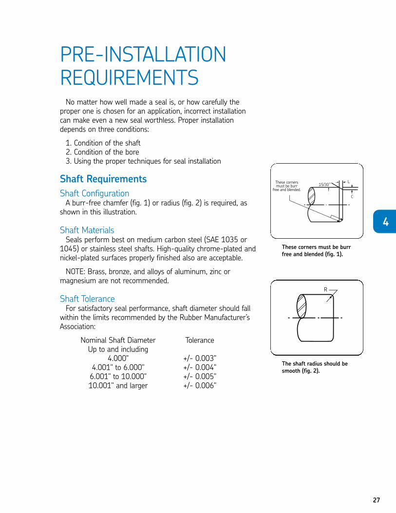
Shaft ConfigurationA burr-free chamfer (fig. 1) or radius (fig. 2) is required, as
shown in this illustration.
Shaft MaterialsSeals perform best on medium carbon steel (SAE 1035 or
1045) or stainless steel shafts. High-quality chrome-plated andnickel-plated surfaces properly finished also are acceptable.
NOTE: Brass, bronze, and alloys of aluminum, zinc ormagnesium are not recommended.
Shaft ToleranceFor satisfactory seal performance, shaft diameter should fall
within the limits recommended by the Rubber Manufacturer’sAssociation:
Nominal Shaft Diameter ToleranceUp to and including
4.000" +/- 0.003"4.001" to 6.000" +/- 0.004"6.001" to 10.000" +/- 0.005"10.001" and larger +/- 0.006"
The shaft radius should besmooth (fig. 2).
4
These corners must be burrfree and blended (fig. 1).
28
Shaft HardnessUnder normal conditions, the shaft’s sealing surface should
be hardened to Rockwell C30 minimum. There is no conclusiveevidence that further hardening will increase seal life.
Shaft FinishThe surface of the shaft, or shaft finish, is critical to proper
seal performance. Ideally, the shaft should be smooth enoughto maintain contact with the seal lip, but rough enough to holdthe lubricant film in place.
Machine lead is always present after the shaft has beenmachined to size on a lathe. It is necessary to dress the shaftsurface to remove the lead introduced during the machiningoperation.
Seal and original equipment (OE) manufacturers agree thatthe following shaft conditions should be met:
• Shaft finish should fall between 10 to 20 micro inches AA (Arithmetical Average)
• Shafts should be ground with mixed number rpm ratios• The finish or surface of the shaft should be free of machine lead
• The entrance edge should be chamfered or rounded
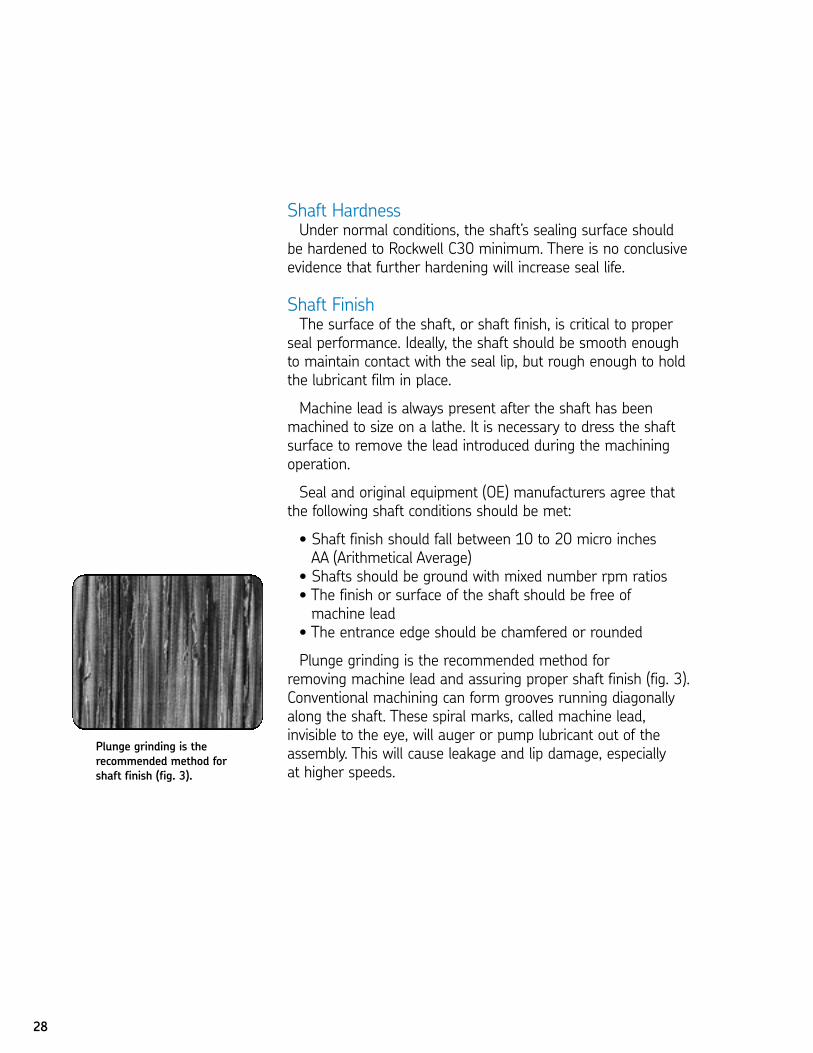
Plunge grinding is the recommended method forremoving machine lead and assuring proper shaft finish (fig. 3).Conventional machining can form grooves running diagonallyalong the shaft. These spiral marks, called machine lead, invisible to the eye, will auger or pump lubricant out of theassembly. This will cause leakage and lip damage, especially at higher speeds.
Plunge grinding is the recommended method forshaft finish (fig. 3).
29
However, even plunge grinding can sometimes causemachine lead. To avoid this problem, follow these finishing recommendations:1. Dress the grinding wheel gradually, using a cluster-head tool.
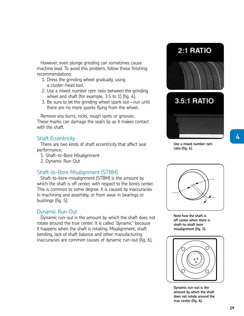
2. Use a mixed number rpm ratio between the grindingwheel and shaft (for example, 3.5 to 1) (fig. 4).
3. Be sure to let the grinding wheel spark out—run untilthere are no more sparks flying from the wheel.
Remove any burrs, nicks, rough spots or grooves. These marks can damage the seal’s lip as it makes contactwith the shaft.
Shaft EccentricityThere are two kinds of shaft eccentricity that affect seal
performance.1. Shaft-to-Bore Misalignment2. Dynamic Run-Out
Shaft-to-Bore Misalignment (STBM)Shaft-to-bore-misalignment (STBM) is the amount by
which the shaft is off center, with respect to the bore’s center.This is common to some degree. It is caused by inaccuracies in machining and assembly, or from wear in bearings orbushings (fig. 5).
Dynamic Run-OutDynamic run-out is the amount by which the shaft does not
rotate around the true center. It is called “dynamic” because it happens when the shaft is rotating. Misalignment, shaftbending, lack of shaft balance and other manufacturing inaccuracies are common causes of dynamic run-out (fig. 6).
Use a mixed number rpmratio (fig. 4).
Note how the shaft is off center when there is shaft-to-shaft bore misalignment (fig. 5).
4
Dynamic run-out is theamount by which the shaftdoes not rotate around thetrue center (fig. 6).
30
Seals can handle more STBM than dynamic run-out. Too much eccentricity tends to increase friction and create abnormal wear. The faster the seal lip must move, the less distance it can travel while still following the shaft. So, as shaftspeed (rpm) increases, the allowable amount of dynamic run-out decreases.
Refer to the Recommended Operating Conditions Chart in theSKF Handbook of Seals (Catalog #457010) for shaft-to-boremisalignment and dynamic run-out ranges.
Shaft SpeedMaximum speeds for effective seal operation depend on
a number of factors. These include shaft finish, pressure, temperature, eccentricity, lubricant or fluid being retained, seal type and other conditions. For example, shaft speeds may be increased when shaft finish is improved or eccentricity(run-out) is reduced.
Bore Requirements
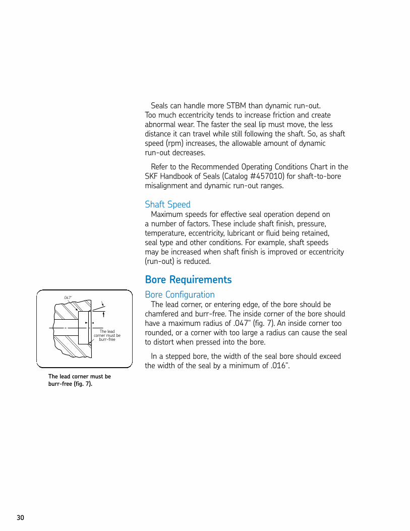
Bore ConfigurationThe lead corner, or entering edge, of the bore should be
chamfered and burr-free. The inside corner of the bore shouldhave a maximum radius of .047" (fig. 7). An inside corner toorounded, or a corner with too large a radius can cause the sealto distort when pressed into the bore.
In a stepped bore, the width of the seal bore should exceedthe width of the seal by a minimum of .016".
The lead corner must beburr-free (fig. 7).
31
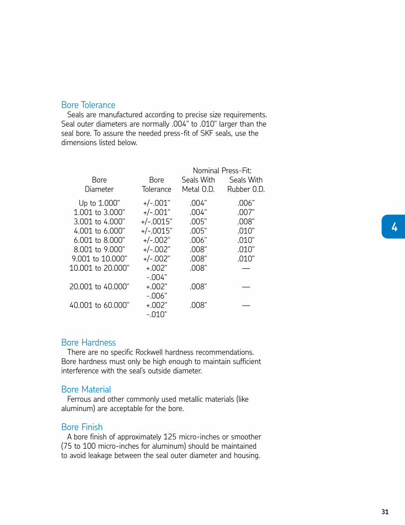
Bore ToleranceSeals are manufactured according to precise size requirements.
Seal outer diameters are normally .004" to .010" larger than theseal bore. To assure the needed press-fit of SKF seals, use thedimensions listed below.
Nominal Press-Fit:Bore Bore Seals With Seals With
Diameter Tolerance Metal O.D. Rubber 0.D.
Up to 1.000" +/-.001" .004" .006"1.001 to 3.000" +/-.001" .004" .007"3.001 to 4.000" +/-.0015" .005" .008"4.001 to 6.000" +/-.0015" .005" .010"6.001 to 8.000" +/-.002" .006" .010"8.001 to 9.000" +/-.002" .008" .010"9.001 to 10.000" +/-.002" .008" .010"10.001 to 20.000" +.002" .008" —
-.004"20.001 to 40.000" +.002" .008" —
-.006"40.001 to 60.000" +.002" .008" —
-.010"
Bore HardnessThere are no specific Rockwell hardness recommendations.
Bore hardness must only be high enough to maintain sufficientinterference with the seal’s outside diameter.
Bore MaterialFerrous and other commonly used metallic materials (like
aluminum) are acceptable for the bore.
Bore FinishA bore finish of approximately 125 micro-inches or smoother
(75 to 100 micro-inches for aluminum) should be maintained to avoid leakage between the seal outer diameter and housing.
4
32
SKF factory-applies a coating of Bore-Tite to the O.D. on popular seals. During installation, this coating efficiently fillsminor bore imperfections.
Pre-LubricationPre-lubrication of the seal lip is an important step that should
not be forgotten. This provides a film on which the seal can rideuntil there is ample lubrication in the seal cavity.
The best pre-lube to use is the lubricant being retained. Thisavoids any problems caused by mixing two different lubricants.
For example, it avoids the chance of picking a pre-lube whichmight damage the seal lip, causing it to shrink, swell, or soften.It also eliminates the possibility of using a grease with a limitof 200ºF in an application where the temperature might run250ºF or 300ºF.
ToolsThe best tool to use for seal installation is either an arbor or
hydraulic press that applies uniform pressure against the seal. If a press is not available or practical, use a round tool such asa bearing cup. If the tool must follow the seal into the bore, itshould be slightly smaller than the O.D. of the seal. (An outsidediameter ten thousandths of an inch smaller than the bore isideal.) For best results, the center of the tool should be open so that pressure is only applied at the outer edge of the seal.
33
HammeringSeals that are to be flush with the outside of the housing can
be pressed in with a block of wood. In this case, it is acceptableto use a steel hammer and apply force on a wood workpiece.
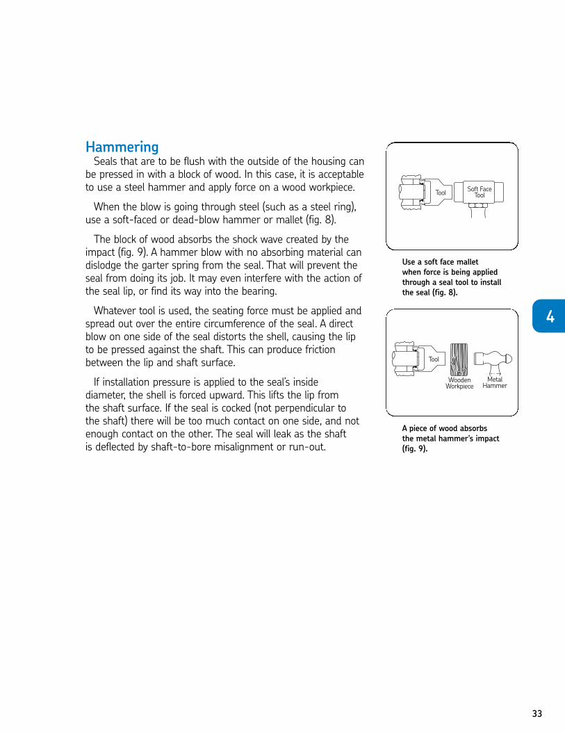
When the blow is going through steel (such as a steel ring),use a soft-faced or dead-blow hammer or mallet (fig. 8).
The block of wood absorbs the shock wave created by theimpact (fig. 9). A hammer blow with no absorbing material candislodge the garter spring from the seal. That will prevent theseal from doing its job. It may even interfere with the action ofthe seal lip, or find its way into the bearing.
Whatever tool is used, the seating force must be applied andspread out over the entire circumference of the seal. A directblow on one side of the seal distorts the shell, causing the lip to be pressed against the shaft. This can produce frictionbetween the lip and shaft surface.
If installation pressure is applied to the seal’s inside diameter, the shell is forced upward. This lifts the lip from the shaft surface. If the seal is cocked (not perpendicular to the shaft) there will be too much contact on one side, and notenough contact on the other. The seal will leak as the shaftis deflected by shaft-to-bore misalignment or run-out.
Use a soft face malletwhen force is being appliedthrough a seal tool to installthe seal (fig. 8).
A piece of wood absorbs the metal hammer’s impact(fig. 9).
4
34
Tool ChecklistRemember to use tools that save rather than spoil the seal.
RECOMMENDED TOOLSArbor pressSoft-face hammerInstallation tools in order of preference:Tool that is tailor-made for seal installationStandard driving plugOld bearing cupWood block
AVOIDDirect hammer blows on seal faceDrift or punchSteel-to-steelChisel or screwdriverStarting seal into bore at an angle (cocked)
35
CHAPTER 4 REVIEWTo take this test simply place a card or sheet of paper under the first question.
After you’ve read it (and answered it to yourself), slide the paper down below thenext question. The correct answer to the first problem will appear directly to theright of the new question. Be sure not to skip any of the questions. This learningtechnique assures more than four times the normal retention rate for even thistechnical subject.
01. Proper seal installation depends on the .N a. condition of the shaftN b. condition of the boreN c. use of correct techniques for seal placementN d. all of the above
1. D
02. Shaft finish is critical to proper seal performance. Therefore, .N a. the shaft surface requires machine leadN b. the leading edge must be chamfered or roundedN c. the surface finish should be between 5-7 micro-inchesN d. all of the above
2. B
03. Maximum speed for effective seal performance is affected by .
N a. operating temperatureN b. lubricant retentionN c. internal pressureN d. all of the above
3. D
04. To avoid leakage between the seal’s outer diameter and housing, .
N a. the bore finish should be approximately 125 micro-inchesN b. the inside corners must be well-roundedN c. a specific Rockwell hardness must be followedN d. all of the above
4. A
05. The seal can be installed in the bore after .N a. the shaft has been checkedN b. the bore has been checkedN c. pre-lubricationN d. all of the above
5. D
4
06. A chisel or screwdriver is for seal installation.N a. recommendedN b. never recommendedN c. always usedN d. none of the above
6. B07. Seals perform best on aluminum or zinc shafts.
N True N False7. F
08. Ideally, the shaft should be smooth enough to keep in contact with the seal lip, but rough enough to keep the lubricant film in place.
N True N False8. T
09. Shafts require constant polishing and machining.N True N False
9. F10. Plunge grinding is the recommended method to obtain a smooth
shaft finish.N True N False
10. T11. Shaft-to-bore misalignment (STBM) is often caused by inaccuracies in
machining and assembly. N True N False
11. T12. Dynamic run-out is the amount by which the shaft is off center
with respect to the bore’s center.N True N False
12. F13. Revolutions per minute (rpm) of the shaft is a better indicator of seal
performance than feet per minute (fPm).N True N False
13. F14. The recommended pre-lube for a seal is oil.
N True N False14. F
15. A direct blow on one side of the seal generates force out and around the seal’s entire circumference.
N True N False15. F
36
37
GREASE SEALINSTALLATIONIn this chapter, you will find complete instructions
for installing grease seals on the front and drive axle.
First, you should get in the habit of replacing the seal whenever you pull the wheel.
The old seal may have been nicked or bent when the wheelwas removed. Some of the seal’s press fit in the hub may havebeen lost during removal of the bearing. If so, the seal will notfit as tight as it should which will prevent it from retaining lubeand excluding dirt. Reusing an old seal can cause problemssuch as failure of the wheel bearing or brake lining.
Before discarding the old seal, check it for damage. This willbe explained in Chapter 6. Then proceed with the followingguidelines for seal installation.
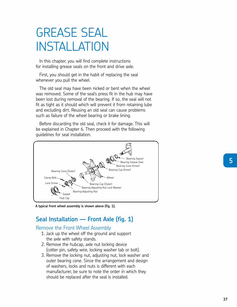
Seal Installation — Front Axle (fig. 1)
Remove the Front Wheel Assembly1. Jack up the wheel off the ground and supportthe axle with safety stands.
2. Remove the hubcap, axle nut locking device (cotter pin, safety wire, locking washer tab or bolt).
3. Remove the locking nut, adjusting nut, lock washer andouter bearing cone. Since the arrangement and design of washers, locks and nuts is different with each manufacturer, be sure to note the order in which theyshould be replaced after the seal is installed.
A typical front wheel assembly is shown above (fig. 1).
5
38
4. Slide the wheel and hub assembly off the spindle. Becareful not to drag the inner bearing over the spindlethread. If possible chain the wheel to the dolly for safety.
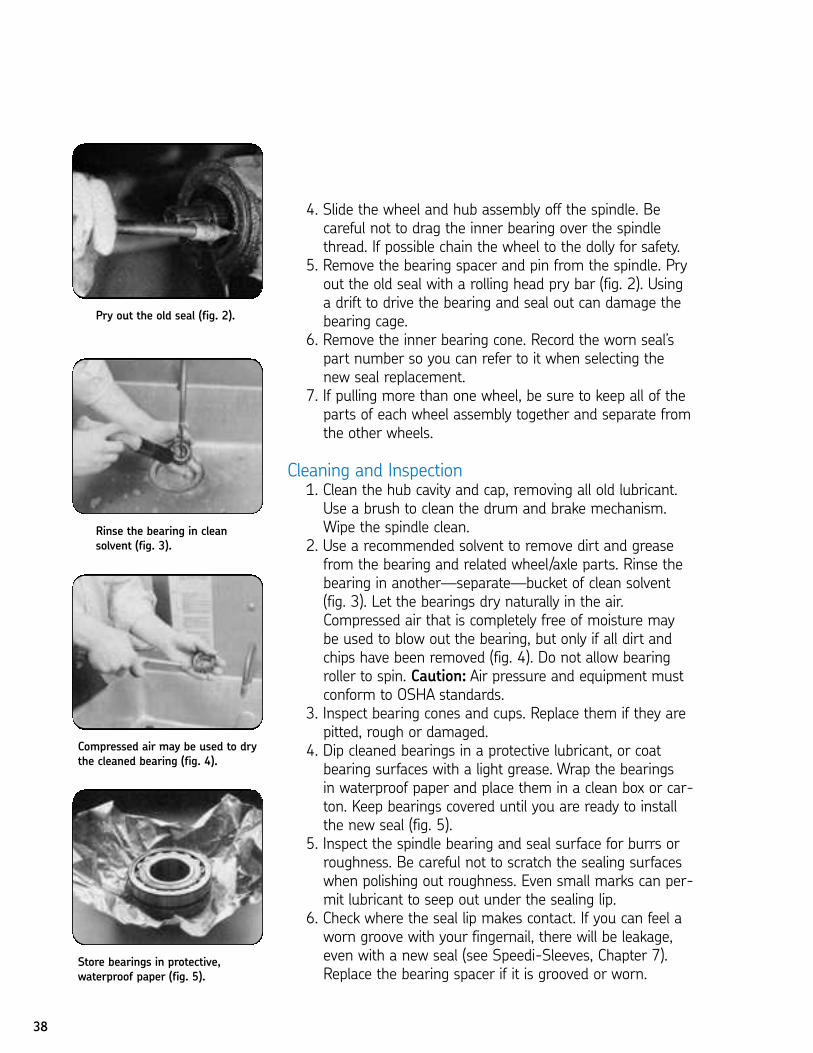
5. Remove the bearing spacer and pin from the spindle. Pryout the old seal with a rolling head pry bar (fig. 2). Usinga drift to drive the bearing and seal out can damage thebearing cage.
6. Remove the inner bearing cone. Record the worn seal’spart number so you can refer to it when selecting thenew seal replacement.
7. If pulling more than one wheel, be sure to keep all of theparts of each wheel assembly together and separate fromthe other wheels.
Cleaning and Inspection1. Clean the hub cavity and cap, removing all old lubricant.Use a brush to clean the drum and brake mechanism.Wipe the spindle clean.
2. Use a recommended solvent to remove dirt and greasefrom the bearing and related wheel/axle parts. Rinse thebearing in another—separate—bucket of clean solvent(fig. 3). Let the bearings dry naturally in the air.Compressed air that is completely free of moisture maybe used to blow out the bearing, but only if all dirt andchips have been removed (fig. 4). Do not allow bearingroller to spin. Caution: Air pressure and equipment mustconform to OSHA standards.
3. Inspect bearing cones and cups. Replace them if they arepitted, rough or damaged.
4. Dip cleaned bearings in a protective lubricant, or coatbearing surfaces with a light grease. Wrap the bearings in waterproof paper and place them in a clean box or car-ton. Keep bearings covered until you are ready to installthe new seal (fig. 5).
5. Inspect the spindle bearing and seal surface for burrs orroughness. Be careful not to scratch the sealing surfaceswhen polishing out roughness. Even small marks can per-mit lubricant to seep out under the sealing lip.
6. Check where the seal lip makes contact. If you can feel aworn groove with your fingernail, there will be leakage,even with a new seal (see Speedi-Sleeves, Chapter 7).Replace the bearing spacer if it is grooved or worn.
Pry out the old seal (fig. 2).
Rinse the bearing in cleansolvent (fig. 3).
Compressed air may be used to drythe cleaned bearing (fig. 4).
Store bearings in protective,waterproof paper (fig. 5).
39
Installation Checklist1. Check the bore. The leading edge must be deburred. A roundedcorner or chamfer should be provided.
2. Check the shaft. Remove surface nicks, burrs, grooves and spiralmachine marks (machine lead).
3. Check the shaft end. Remove burrs or sharp edges. The shaft endshould be chamfered in applications where the shaft enters the sealagainst the sealing lip.
4. Check splines and keyways. Sharp edges should be covered with alubricated assembly sleeve, shim stock or tape to protect the seal lip.
5. Check dimensions. Be sure shaft and bore diameters match thosespecified for the seal selected.
6. Check for parts interference.Watch out for other machine parts that might rub against the seal and cause friction and damaging heat.
7. Check the seal. Damage may have occurred prior to installation. A sealing lip that is turned back, cut or otherwise damaged shouldbe replaced.
8. Check seal direction. Make sure that the new seal faces in the samedirection as the original one. Generally, the lip faces the lubricant orfluid to be retained.
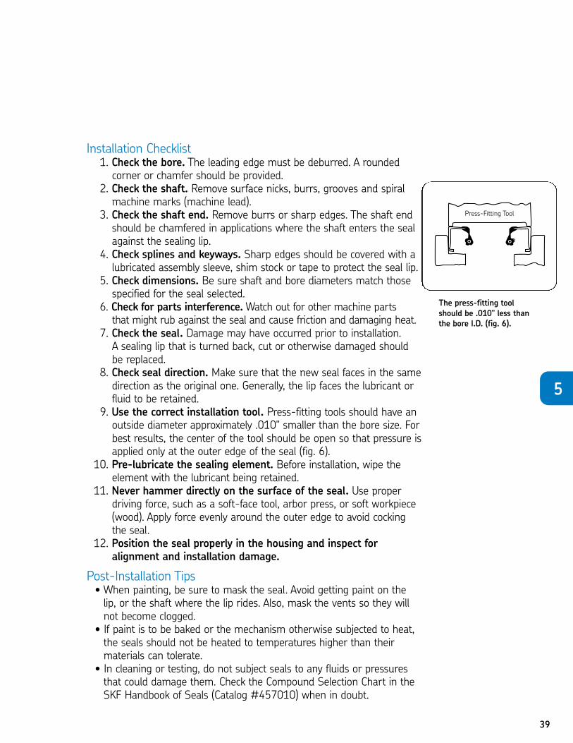
9. Use the correct installation tool. Press-fitting tools should have anoutside diameter approximately .010" smaller than the bore size. Forbest results, the center of the tool should be open so that pressure isapplied only at the outer edge of the seal (fig. 6).
10. Pre-lubricate the sealing element. Before installation, wipe theelement with the lubricant being retained.
11. Never hammer directly on the surface of the seal. Use properdriving force, such as a soft-face tool, arbor press, or soft workpiece(wood). Apply force evenly around the outer edge to avoid cockingthe seal.
12. Position the seal properly in the housing and inspect foralignment and installation damage.
Post-Installation Tips• When painting, be sure to mask the seal. Avoid getting paint on thelip, or the shaft where the lip rides. Also, mask the vents so they willnot become clogged.
• If paint is to be baked or the mechanism otherwise subjected to heat,the seals should not be heated to temperatures higher than theirmaterials can tolerate.
• In cleaning or testing, do not subject seals to any fluids or pressuresthat could damage them. Check the Compound Selection Chart in theSKF Handbook of Seals (Catalog #457010) when in doubt.
5
The press-fitting toolshould be .010" less thanthe bore I.D. (fig. 6).
40
Reassemble the Wheel1. Pack the hub cavity between the two bearing cups with anapproved wheel bearing grease to the level of the cup’ssmallest diameter.
2. Pack the bearing cones, using a pressure packer if possible.If not, force the grease into the cavities between the rollersand cage by hand from the large end of the cone. Coat theends of the rollers freely with grease.
3. Insert the inner bearing cone in the grease-filled hub. Placethe pre-lubed seal in the hub with the lip facing the bearingcone. Seal it properly.
4. Position the spacer on the spindle. Align the hole and pin.Apply a light film of lubricant to the spindle to preventrusting.
5. Use a wheel dolly to center the wheel assembly on the spindle. Push the wheel on far enough so the seal is in safecontact with its riding surface on the bearing spacer orspindle. Install the outer bearing cone, washer and adjustingnut in reverse order of removal.
6. Adjust the bearing according to the manufacturer’s instructions. Secure the locking nut and locking device. Fill the hub cap with grease, position the new gasketwith sealant on the hub cap, and install.
7. For oil bath seals replacement, see Scotseal, Chapter 8.
Seal Installation -Drive Axle
Remove the Drive Wheel Assembly1. Jack up the wheel. Support the axle with safety stands.2. Remove the axle flange nuts and lock washers. Install pullingscrews in axle flange holes, if provided. If not, strike the axleflange in the center sharply with a heavy hammer. It mayrequire several blows to bounce the shaft loose so thetapered washers and axle shaft can be removed.
3. Loosen the bearing lock ring nut set screw (when used) andremove the lock nut. Some drive axles use a locking washerbetween the outer nut and the bearing adjusting nut. One ormore of the tabs bent over the outer nut and seal assemblymust be bent away from the nut before a socket of the correct size will fit over the nut. Then remove the lock nut,lock washer or ring, and adjusting nut.
All other procedures for wheel removal, inspection, seal installation and reassembly are the same as for the front axle.
41
Other ApplicationsInstallation procedures for transmissions, pinions, prop shafts,
timing covers and other fleet seal applications are somewhatsimilar, but with these precautions:
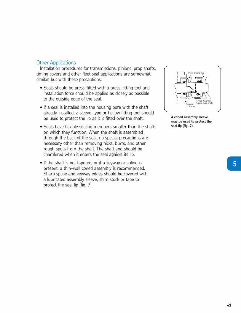
• Seals should be press-fitted with a press-fitting tool andinstallation force should be applied as closely as possible to the outside edge of the seal.
• If a seal is installed into the housing bore with the shaftalready installed, a sleeve-type or hollow fitting tool shouldbe used to protect the lip as it is fitted over the shaft.
• Seals have flexible sealing members smaller than the shaftson which they function. When the shaft is assembledthrough the back of the seal, no special precautions arenecessary other than removing nicks, burrs, and otherrough spots from the shaft. The shaft end should be chamfered when it enters the seal against its lip.
• If the shaft is not tapered, or if a keyway or spline is present, a thin-wall coned assembly is recommended.Sharp spline and keyway edges should be covered with a lubricated assembly sleeve, shim stock or tape to protect the seal lip (fig. 7).
A coned assembly sleevemay be used to protect theseal lip (fig. 7),
5
To take this test, simply place a card or sheet of paper under the first question.After you’ve read it (and answered it to yourself), slide the paper down below thenext question. The correct answer to the first problem will appear directly to theright of the new question. Be sure not to skip any of the questions. This learningtechnique assures more than four times the normal retention rate for even thistechnical subject.
01. An old seal should be replaced when .N a. it has been nicked N b. some of the press-fit in the hub is lostN c. it has been bentN d. all of the above
1. D02. Reusing an old seal can cause failure of the .
N a. wheelN b. brake liningN c. bearingN d. any of the above
2. D03. can damage the bearing cage.
N a. Prying out the old seal with a rolling head pry barN b. Driving the bearing and seal out with a driftN c. Removing the inner bearing coneN d. All of the above
3. B04. Bearing cones and cups should be if they are pitted
or damaged.N a. lubricatedN b. replacedN c. rotatedN d. all of the above
4. B05. A light film of prevents rusting on the spindle.
N a. SKF Bore-TiteN b. lubricantN c. wax paperN d. powdered metal epoxy type filler
5. B 06. The press-fitting tool used in installation should be the bore I.D.
N a. .010" less thanN b. .010" more thanN c. .025" less thanN d. equal to
6. A
42
CHAPTER 5 REVIEW
43
07. A thin-wall coned assembly sleeve is recommended when .N a. the shaft is not taperedN b. a keyway is discoveredN c. a spline is presentN d. all of the above
7. D08. Edges of the keyway and spline should be lubricated with .
N a. straight mineral oilN b. a hard, fibrous greaseN c. ordinary engine oilN d. SKF Bore-Tite
8. B 09. When you pull the wheel, change the seal.
N True N False9. T
10. It is unnecessary to check the old seal for damage beforedumping it.
N True N False10. F
11. Small scratches on the shaft can allow some lubricant to seepunder the sealing lip.
N True N False11. T
12. Replace bearing cups and cones if they are pitted, roughor damaged.
N True N False12. T
13. All drive axles use a locking washer between the outer nut andthe bearing adjusting nut.
N True N False13. F
14. Use a sleeve-type or hollow fitting tool when installing a sealinto the housing bore of a pinion with the shaft already inserted.
N True N False14. T
15. Seals are press-fitted in transmissions by applying force asclose as possible to the inside edge of the seal.
N True N False15. F
5
44
TROUBLESHOOTINGYou now know the various types of seals available, can select
the right seal for the right application, and are able to install it. Butbefore you replace that next seal, there are some troubleshootingpoints that will round out your knowledge of seals.
Preliminary SurveyThe best way to troubleshoot is to follow a sequence of steps
that should lead you to the problem.1. What was the seal supposed to do? How well has it done thejob in the past? If there is a history of failures, the problemmay not be caused by the seal itself.
2. Was it the right seal? Check the seal’s part number and lookup its recommended applications. If the correct seal has beeninstalled and there is no history of repeated failures, theproblem requires further investigation.
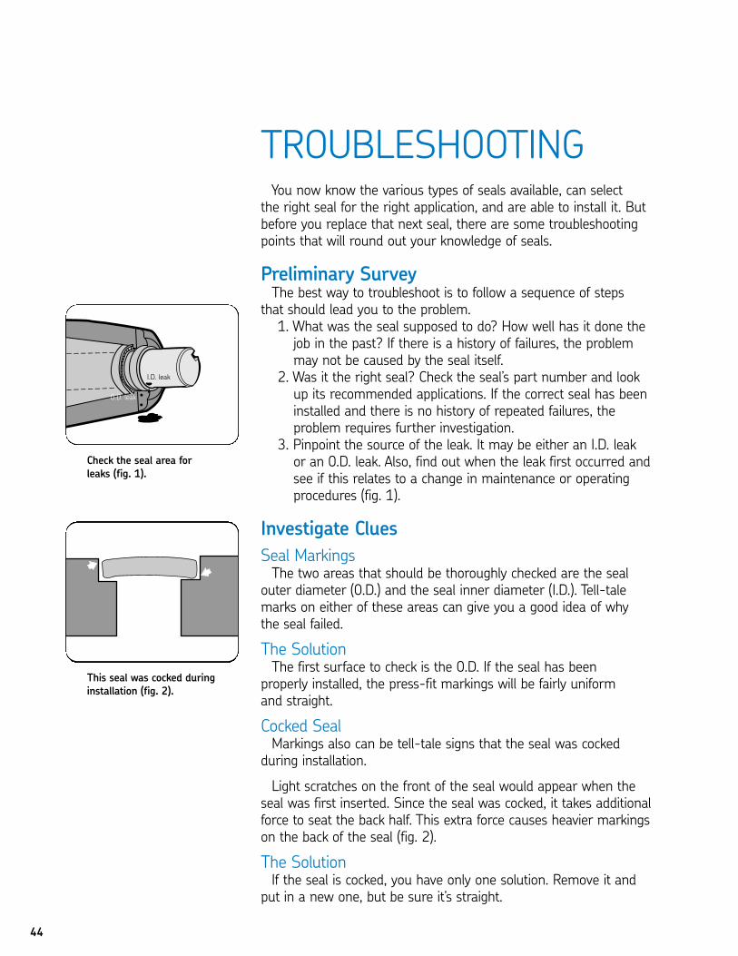
3. Pinpoint the source of the leak. It may be either an I.D. leakor an 0.D. leak. Also, find out when the leak first occurred andsee if this relates to a change in maintenance or operatingprocedures (fig. 1).
Investigate Clues
Seal MarkingsThe two areas that should be thoroughly checked are the seal
outer diameter (0.D.) and the seal inner diameter (I.D.). Tell-talemarks on either of these areas can give you a good idea of why the seal failed.
The SolutionThe first surface to check is the 0.D. If the seal has been
properly installed, the press-fit markings will be fairly uniform and straight.
Cocked SealMarkings also can be tell-tale signs that the seal was cocked
during installation.
Light scratches on the front of the seal would appear when theseal was first inserted. Since the seal was cocked, it takes additionalforce to seat the back half. This extra force causes heavier markingson the back of the seal (fig. 2).
The SolutionIf the seal is cocked, you have only one solution. Remove it and
put in a new one, but be sure it’s straight.
Check the seal area forleaks (fig. 1).
This seal was cocked duringinstallation (fig. 2).
45
Lip Wear PatternsLook for clues in the sealing member of the seal. A small cut or
nick could be the source of the leak. But if everything looks intact,it’s time to look at the wear pattern of the lip.
A new seal that has never been installed has a sharp edge on its sealing lip at the contact point. Following a period of normaloperation, the lip’s sharp edge will be flattened some by normalwear. If the lip has been substantially worn away, the seal may notbe getting enough lubrication, the shaft may be corroded, or thefinish too rough. Extreme wear could also be caused by shaft-whip.
If you find a leaking seal with a wide wear band on one side, buta narrow band on the other, you can suspect high STBM (unless 0.D. markings indicated the seal was cocked). The lip area with thegreatest wear indicates the direction of shaft misalignment.
Initial leakage will generally occur in the area that shows little orno seal wear. This is because of inadequate lip contact. But as theworn side is hardened from excess pressure and heat, it may crackand cause additional leakage.
The SolutionCheck the shaft-to-bore alignment. Correct the alignment.
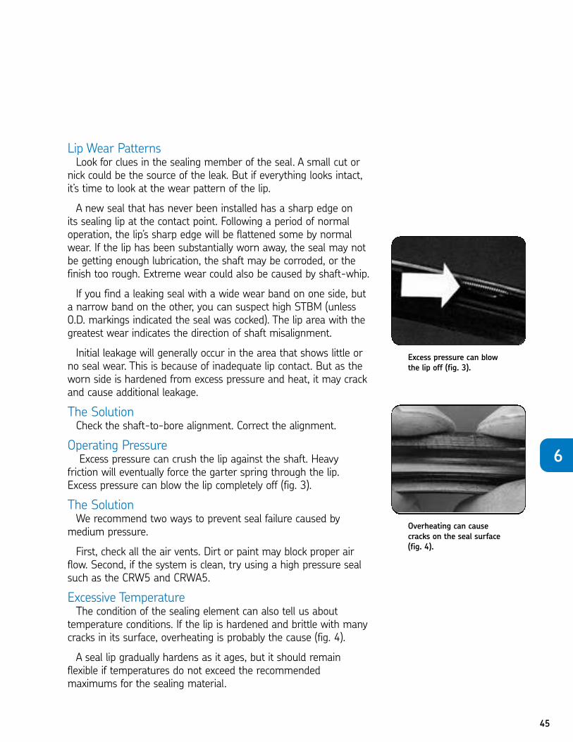
Operating PressureExcess pressure can crush the lip against the shaft. Heavy
friction will eventually force the garter spring through the lip. Excess pressure can blow the lip completely off (fig. 3).
The SolutionWe recommend two ways to prevent seal failure caused by
medium pressure.
First, check all the air vents. Dirt or paint may block proper airflow. Second, if the system is clean, try using a high pressure sealsuch as the CRW5 and CRWA5.
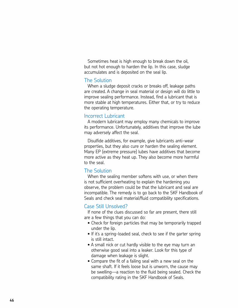
Excessive TemperatureThe condition of the sealing element can also tell us about
temperature conditions. If the lip is hardened and brittle with manycracks in its surface, overheating is probably the cause (fig. 4).
A seal lip gradually hardens as it ages, but it should remain flexible if temperatures do not exceed the recommended maximums for the sealing material.
Excess pressure can blowthe lip off (fig. 3).
Overheating can causecracks on the seal surface(fig. 4).
6
46
Sometimes heat is high enough to break down the oil, but not hot enough to harden the lip. In this case, sludge accumulates and is deposited on the seal lip.
The SolutionWhen a sludge deposit cracks or breaks off, leakage paths
are created. A change in seal material or design will do little toimprove sealing performance. Instead, find a lubricant that ismore stable at high temperatures. Either that, or try to reducethe operating temperature.
Incorrect LubricantA modern lubricant may employ many chemicals to improve
its performance. Unfortunately, additives that improve the lubemay adversely affect the seal.
Disulfide additives, for example, give lubricants anti-wearproperties, but they also cure or harden the sealing element.Many EP (extreme pressure) lubes have additives that becomemore active as they heat up. They also become more harmfulto the seal.
The SolutionWhen the sealing member softens with use, or when there
is not sufficient overheating to explain the hardening youobserve, the problem could be that the lubricant and seal areincompatible. The remedy is to go back to the SKF Handbook ofSeals and check seal material/fluid compatibility specifications.
Case Still Unsolved?If none of the clues discussed so far are present, there still
are a few things that you can do:• Check for foreign particles that may be temporarily trappedunder the lip.
• If it’s a spring-loaded seal, check to see if the garter springis still intact.
• A small nick or cut hardly visible to the eye may turn anotherwise good seal into a leaker. Look for this type ofdamage when leakage is slight.
• Compare the fit of a failing seal with a new seal on thesame shaft. If it feels loose but is unworn, the cause maybe swelling—a reaction to the fluid being sealed. Check thecompatibility rating in the SKF Handbook of Seals.
47
CHAPTER 6 REVIEWTo take this test, simply place a card or sheet of paper under the first question.
After you’ve read it (and answered it to yourself), slide the paper down below thenext question. The correct answer to the first problem will appear directly to theright of the new question. Be sure not to skip any of the questions. This learningtechnique assures more than four times the normal retention rate for even thistechnical subject.
01. An alternating pattern of smooth and marked areas on the 0.D. indicates thatthe seal was probably .
N a. pressed into an out-of-round, over-size bore N b. cocked during installation N c. flattened by normal wearN d. misaligned
1. A
02. If a seal is cocked, it should be .N a. replacedN b. straightenedN c. ignoredN d. lubricated
2. A
03. Improper wear can cause a shaft to leak as a result of .N a. excessive STBMN b. excessive pressureN c. a cocked sealN d. all of the above
3. D
04. Pressure-caused seal failures may be corrected by .N a. opening air vents which may be plugged with dirt or paintN b. straightening the sealN c. reducing operating temperatureN d. all of the above
4. A
05. If the seal lip is hardened and brittle with many cracks in its surface,is probably the cause.
N a. pressureN b. eccentricityN c. overheatingN d. a cocked seal
5. C
6
06. Disulfide additives .N a. give lubricants anti-wear propertiesN b. harden the sealing elementN c. both of the aboveN d. neither of the above
6. C07. Many seal failures can be traced back to the condition of the
shaft or bore, or to poor installation.N True N False
7. T08. The first surface to check for wear patterns or markings is the
inside diameter (I.D.) of the seal.N True N False
8. F09. Improper installation can cause the seal to leak.
N True N False9. T
10. If the lip of the seal wears away during normal operation, lesslubrication is required by the seal.
N True N False10. F
11. If a leaking seal has a wide wear band on one side and a narrowband on the other, high STBM can be suspected.
N True N False11. T
12. Heavy friction caused by excess pressure will eventually forcethe garter spring through the lip.
N True N False12. T
13. If a sealing lip is hardened and brittle with cracks in the surface,the cause is probably excessive temperature.
N True N False13. T
14. Chemicals that are used to improve a lubricant’s performancewill not spoil a seal.
N True N False14. F
15. A small cut or nick on the sealing lip has no damaging effecton a good seal.
N True N False15. F
48
49
WEAR SLEEVESContinuous contact between a rotating shaft and a seal always
causes shaft polishing friction. Under normal operating conditions,the friction causes a slight wear track on the shaft.
But, as operating conditions worsen, shaft wear can accelerate.Heat, dirt, excessive speed, lack of lubrication, eccentricity or acocked seal can produce a deep groove on the surface. The ultimate result is a leak.
If this groove can be felt with a paper clip or with your fingernail, it has become too deep to accommodate a replacement sealwithout leaking.
There are three solutions:1. Reworking or remetalizing the shaft surface at a machineshop—High cost, requires hours of fleet downtime.
2. Replacing the shaft—Also expensive, with substantial fleetdowntime.
3. Installing a wear sleeve—Comparatively low in cost with virtually no downtime.
When it comes to correcting yokes, flanges and shafts, a wearsleeve requires the least amount of downtime and cost. Appliedover the damaged shaft, it makes the shaft usable again, elimi-nates shaft leaks, and smooths out damaged surfaces—all fasterand less expensive than re-metalizing or replacing the shaft.
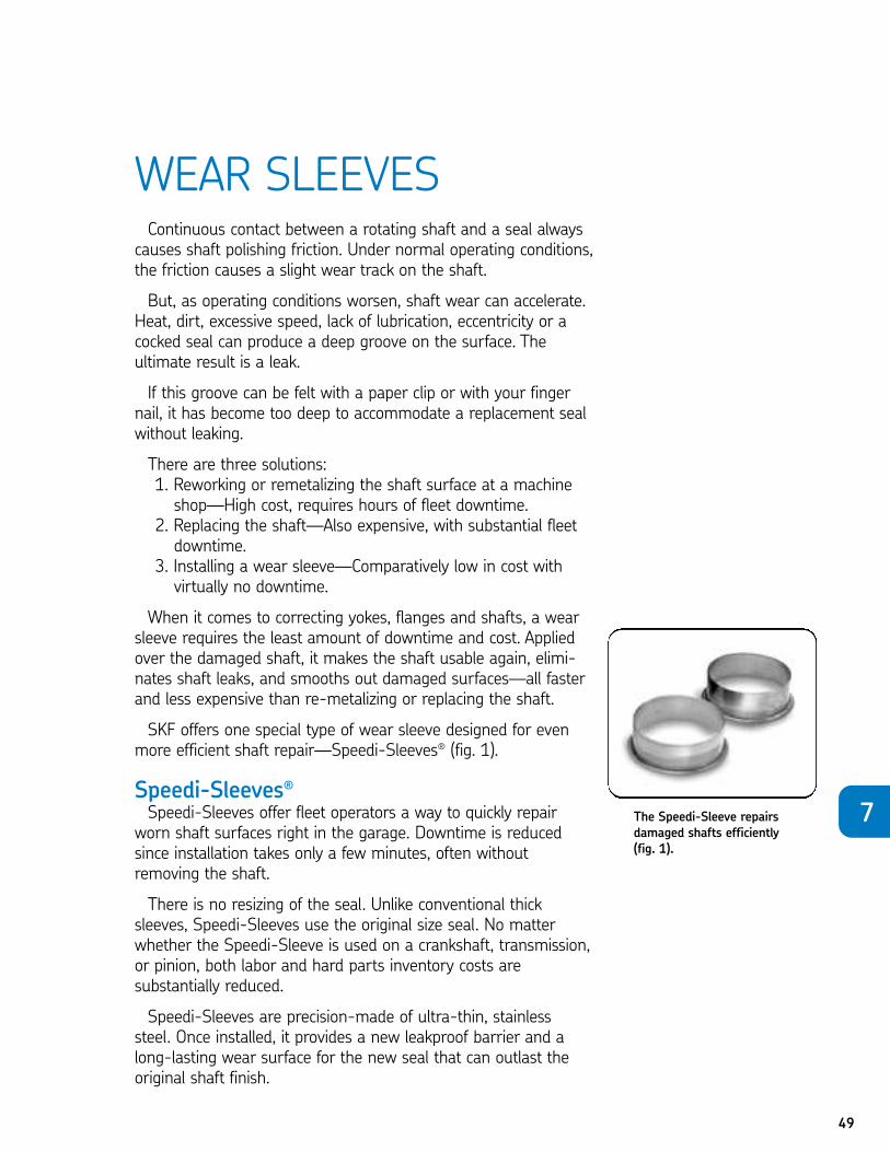
SKF offers one special type of wear sleeve designed for evenmore efficient shaft repair—Speedi-Sleeves® (fig. 1).
Speedi-Sleeves®Speedi-Sleeves offer fleet operators a way to quickly repair
worn shaft surfaces right in the garage. Downtime is reducedsince installation takes only a few minutes, often withoutremoving the shaft.
There is no resizing of the seal. Unlike conventional thicksleeves, Speedi-Sleeves use the original size seal. No matterwhether the Speedi-Sleeve is used on a crankshaft, transmission,or pinion, both labor and hard parts inventory costs are substantially reduced.
Speedi-Sleeves are precision-made of ultra-thin, stainless steel. Once installed, it provides a new leakproof barrier and along-lasting wear surface for the new seal that can outlast theoriginal shaft finish.
The Speedi-Sleeve repairsdamaged shafts efficiently(fig. 1).
7
50
ADVANTAGES+ Corrects crankshaft, pinion, and transmission surfaces+ Repairs yokes, flanges and shafts+ Can be used without changing the seal size or part number+ Requires little downtime
Each sleeve is built with a removable flange and includes a special tool for installation. This tool is placed over theSpeedi-Sleeve. Both the tool and sleeve are tapped into position on the shaft, yoke or flange.
The flange on the Speedi-Sleeve allows the sleeve to bepulled-on instead of pushed-on, eliminating sleeve distortion.
When the Speedi-Sleeve is positioned, the tool slides off easily. The flange can be left intact, or cut and peeled off alonga pre-cut line.
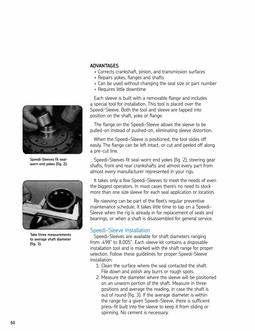
Speedi-Sleeves fit seal-worn end yokes (fig. 2), steering gearshafts, front and rear crankshafts and almost every part fromalmost every manufacturer represented in your rigs.
It takes only a few Speedi-Sleeves to meet the needs of eventhe biggest operators. In most cases there’s no need to stockmore than one size sleeve for each seal application or location.
Re-sleeving can be part of the fleet’s regular preventivemaintenance schedule. It takes little time to tap on a Speedi-Sleeve when the rig is already in for replacement of seals andbearings, or when a shaft is disassembled for general service.
Speedi-Sleeve InstallationSpeedi-Sleeves are available for shaft diameters ranging
from .498" to 8.005". Each sleeve kit contains a disposableinstallation tool and is marked with the shaft range for properselection. Follow these guidelines for proper Speedi-Sleeveinstallation:1. Clean the surface where the seal contacted the shaft. File down and polish any burrs or rough spots.
2. Measure the diameter where the sleeve will be positionedon an unworn portion of the shaft. Measure in threepositions and average the reading, in case the shaft is out of round (fig. 3). If the average diameter is within the range for a given Speedi-Sleeve, there is sufficientpress-fit built into the sleeve to keep it from sliding orspinning. No cement is necessary.
Speedi-Sleeves fit seal-worn end yokes (fig. 2).
Take three measurementsto average shaft diameter(fig. 3).
51
3. If the groove does not require filling, apply a light layer ofnon-hardening sealant to the inner surface of the sleeve.
4. If the shaft is deeply scored, fill the groove with powderedmetal epoxy type filler. Install Speedi-Sleeve before themetal hardens.
5. Undersize shafts: Shaft diameters a few thousandthsunder the published minimum may be sleeved if cementis used.
6. Oversize shafts: Diameters larger than the publishedmaximum can be sleeved if first machined with a finish125 rms or better. Note that the use of Speedi-Sleeveeliminates the need for special grinding or preparation of the surface.
7. Speedi-Sleeves are wide enough to cover the wearpattern of both standard and wider combination seals.Where extra wide combinations are encountered, a second sleeve can be installed to butt against the first.The flange is then peeled off to provide the clearancenecessary for the seal housing to slide into place. TheSpeedi-Sleeve installation flange can be left in place as an oil flinger to prevent surges of oil from being pumpedinto the seal lip by the action of the adjacent bearing.
8. Determine how far back the sleeve must be positioned to cover the old seal wear tracks. Measure to the exactpoint, or mark directly on the surface.
9. The sleeve must be placed over the worn area, not justbottomed or left flush with the end of the shaft.
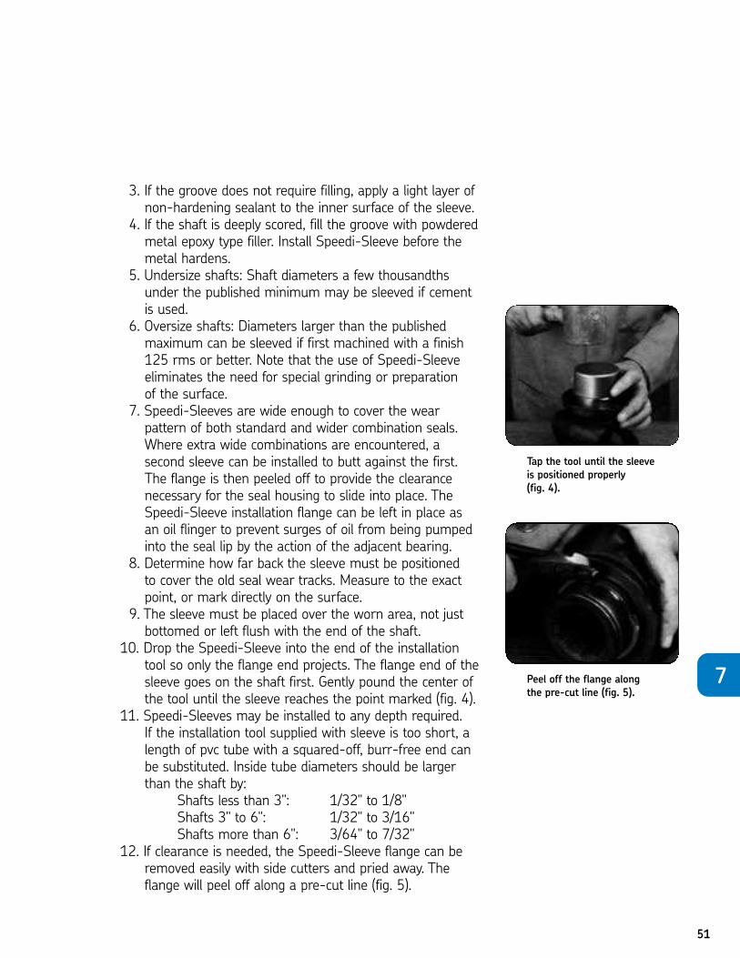
10. Drop the Speedi-Sleeve into the end of the installationtool so only the flange end projects. The flange end of thesleeve goes on the shaft first. Gently pound the center ofthe tool until the sleeve reaches the point marked (fig. 4).
11. Speedi-Sleeves may be installed to any depth required. If the installation tool supplied with sleeve is too short, alength of pvc tube with a squared-off, burr-free end canbe substituted. Inside tube diameters should be largerthan the shaft by:
Shafts less than 3": 1/32" to 1/8"Shafts 3" to 6": 1/32" to 3/16"Shafts more than 6": 3/64" to 7/32"
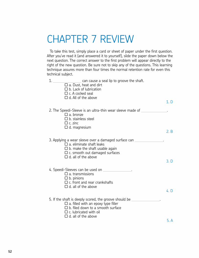
12. If clearance is needed, the Speedi-Sleeve flange can beremoved easily with side cutters and pried away. Theflange will peel off along a pre-cut line (fig. 5).
Tap the tool until the sleeveis positioned properly (fig. 4).
Peel off the flange alongthe pre-cut line (fig. 5).
7
To take this test, simply place a card or sheet of paper under the first question.After you’ve read it (and answered it to yourself), slide the paper down below thenext question. The correct answer to the first problem will appear directly to theright of the new question. Be sure not to skip any of the questions. This learningtechnique assures more than four times the normal retention rate for even thistechnical subject.
01. can cause a seal lip to groove the shaft.N a. Dust, heat and dirtN b. Lack of lubricationN c. A cocked sealN d. All of the above
1. D
02. The Speedi-Sleeve is an ultra-thin wear sleeve made of .N a. bronzeN b. stainless steelN c. zincN d. magnesium
2. B
03. Applying a wear sleeve over a damaged surface can .N a. eliminate shaft leaksN b. make the shaft usable againN c. smooth out damaged surfacesN d. all of the above
3. D
04. Speedi-Sleeves can be used on .N a. transmissionsN b. pinionsN c. front and rear crankshaftsN d. all of the above
4. D
05. If the shaft is deeply scored, the groove should be .N a. filled with an epoxy type fillerN b. filed down to a smooth surfaceN c. lubricated with oilN d. all of the above
5. A
52
CHAPTER 7 REVIEW

53
06. The inside diameter of a pvc tube used to install a 4" Speedi-Sleeve should be larger than the shaft.
N a. at leas 1/2"N b. less than 1/2"N c. 1/32" – 3/16"N d. 3/4"
6. C07. When a seal groove on a shaft can be felt with a fingernail or paper
clip, it must be repaired.N True N False
7. T08. Shaft wear can accelerate as operating conditions worsen.
N True N False8. T
09. Continuous contact between a seal and rotating shaft will always cause shaft polishing friction.
N True N False9. T
10. A deeply scored shaft can only be corrected by remetalizing the surface or replacing the shaft.
N True N False10. F
11. Installing a Speedi-Sleeve is expensive and requires substantial downtime.N True N False
11. F12. The first step to Speedi-Sleeve installation is removal of the shaft.
N True N False12. F
13. The surface of the Speedi-Sleeve can actually outlast the original shaft surface.
N True N False13. T
14. When installing a Speedi-Sleeve over a shaft, the original size seal can still be used.
N True N False14. T
15. Each Speedi-Sleeve is built with a removable flange and includes a special tool for installation.
N True N False15. T
7
Pry out seal (fig. 3).
54
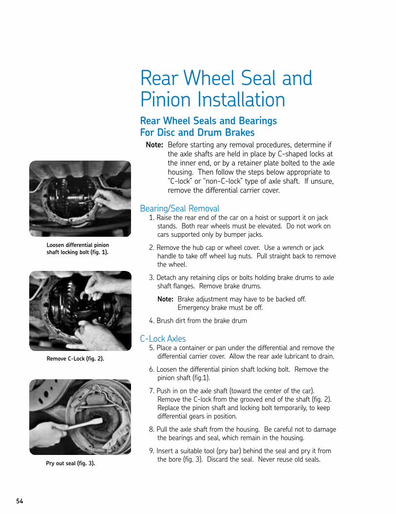
Rear Wheel Seal andPinion Installation Rear Wheel Seals and Bearings For Disc and Drum BrakesNote: Before starting any removal procedures, determine if
the axle shafts are held in place by C-shaped locks atthe inner end, or by a retainer plate bolted to the axlehousing. Then follow the steps below appropriate to“C-lock” or “non-C-lock” type of axle shaft. If unsure,remove the differential carrier cover.
Bearing/Seal Removal1. Raise the rear end of the car on a hoist or support it on jackstands. Both rear wheels must be elevated. Do not work oncars supported only by bumper jacks.
2. Remove the hub cap or wheel cover. Use a wrench or jackhandle to take off wheel lug nuts. Pull straight back to removethe wheel.
3. Detach any retaining clips or bolts holding brake drums to axleshaft flanges. Remove brake drums.
Note: Brake adjustment may have to be backed off.Emergency brake must be off.
4. Brush dirt from the brake drum
C-Lock Axles5. Place a container or pan under the differential and remove the differential carrier cover. Allow the rear axle lubricant to drain.
6. Loosen the differential pinion shaft locking bolt. Remove the pinion shaft (fig.1).
7. Push in on the axle shaft (toward the center of the car).Remove the C-lock from the grooved end of the shaft (fig. 2).Replace the pinion shaft and locking bolt temporarily, to keepdifferential gears in position.
8. Pull the axle shaft from the housing. Be careful not to damage the bearings and seal, which remain in the housing.
9. Insert a suitable tool (pry bar) behind the seal and pry it fromthe bore (fig. 3). Discard the seal. Never reuse old seals.
Loosen differential pinionshaft locking bolt (fig. 1).
Remove C-Lock (fig. 2).
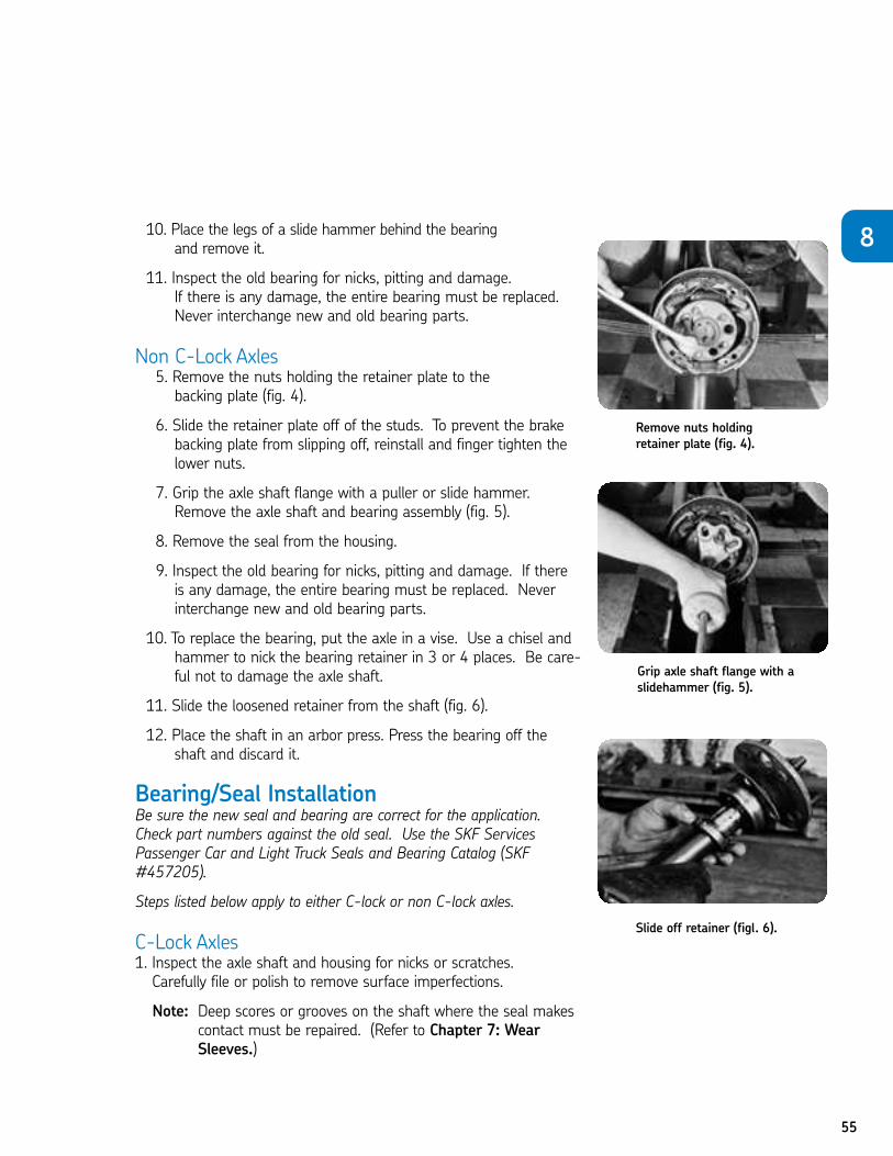
55
10. Place the legs of a slide hammer behind the bearing and remove it.
11. Inspect the old bearing for nicks, pitting and damage. If there is any damage, the entire bearing must be replaced.Never interchange new and old bearing parts.
Non C-Lock Axles5. Remove the nuts holding the retainer plate to the backing plate (fig. 4).
6. Slide the retainer plate off of the studs. To prevent the brakebacking plate from slipping off, reinstall and finger tighten thelower nuts.
7. Grip the axle shaft flange with a puller or slide hammer.Remove the axle shaft and bearing assembly (fig. 5).
8. Remove the seal from the housing.
9. Inspect the old bearing for nicks, pitting and damage. If there is any damage, the entire bearing must be replaced. Neverinterchange new and old bearing parts.
10. To replace the bearing, put the axle in a vise. Use a chisel andhammer to nick the bearing retainer in 3 or 4 places. Be care-ful not to damage the axle shaft.
11. Slide the loosened retainer from the shaft (fig. 6).
12. Place the shaft in an arbor press. Press the bearing off theshaft and discard it.
Bearing/Seal InstallationBe sure the new seal and bearing are correct for the application.Check part numbers against the old seal. Use the SKF ServicesPassenger Car and Light Truck Seals and Bearing Catalog (SKF#457205).
Steps listed below apply to either C-lock or non C-lock axles.
C-Lock Axles1. Inspect the axle shaft and housing for nicks or scratches. Carefully file or polish to remove surface imperfections.
Note: Deep scores or grooves on the shaft where the seal makescontact must be repaired. (Refer to Chapter 7: WearSleeves.)
Remove nuts holdingretainer plate (fig. 4).
8
Grip axle shaft flange with aslidehammer (fig. 5).
Slide off retainer (figl. 6).
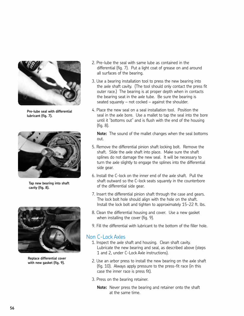
56
2. Pre-lube the seal with same lube as contained in the differential (fig. 7). Put a light coat of grease on and around all surfaces of the bearing.
3. Use a bearing installation tool to press the new bearing into the axle shaft cavity. (The tool should only contact the press fitouter race.) The bearing is at proper depth when in contactsthe bearing seat in the axle tube. Be sure the bearing is seated squarely – not cocked – against the shoulder.
4. Place the new seal on a seal installation tool. Position the seal in the axle bore. Use a mallet to tap the seal into the boreuntil it “bottoms out” and is flush with the end of the housing(fig. 8).
Note: The sound of the mallet changes when the seal bottomsout.
5. Remove the differential pinion shaft locking bolt. Remove theshaft. Slide the axle shaft into place. Make sure the shaftsplines do not damage the new seal. It will be necessary toturn the axle slightly to engage the splines into the differentialside gear.
6. Install the C-lock on the inner end of the axle shaft. Pull the shaft outward so the C-lock seats squarely in the counterboreof the differential side gear.
7. Insert the differential pinion shaft through the case and gears. The lock bolt hole should align with the hole on the shaft.Install the lock bolt and tighten to approximately 15-22 ft. lbs.
8. Clean the differential housing and cover. Use a new gasketwhen installing the cover (fig. 9).
9. Fill the differential with lubricant to the bottom of the filler hole.
Non C-Lock Axles1. Inspect the axle shaft and housing. Clean shaft cavity.Lubricate the new bearing and seal, as described above (steps1 and 2, under C-Lock Axle instructions).
2. Use an arbor press to install the new bearing on the axle shaft(fig. 10). Always apply pressure to the press-fit race (in thiscase the inner race is press fit).
3. Press on the bearing retainer.
Note: Never press the bearing and retainer onto the shaftat the same time.
Pre-lube seal with differentiallubricant (fig. 7).
Tap new bearing into shaftcavity (fig. 8).
Replace differential coverwith new gasket (fig. 9).
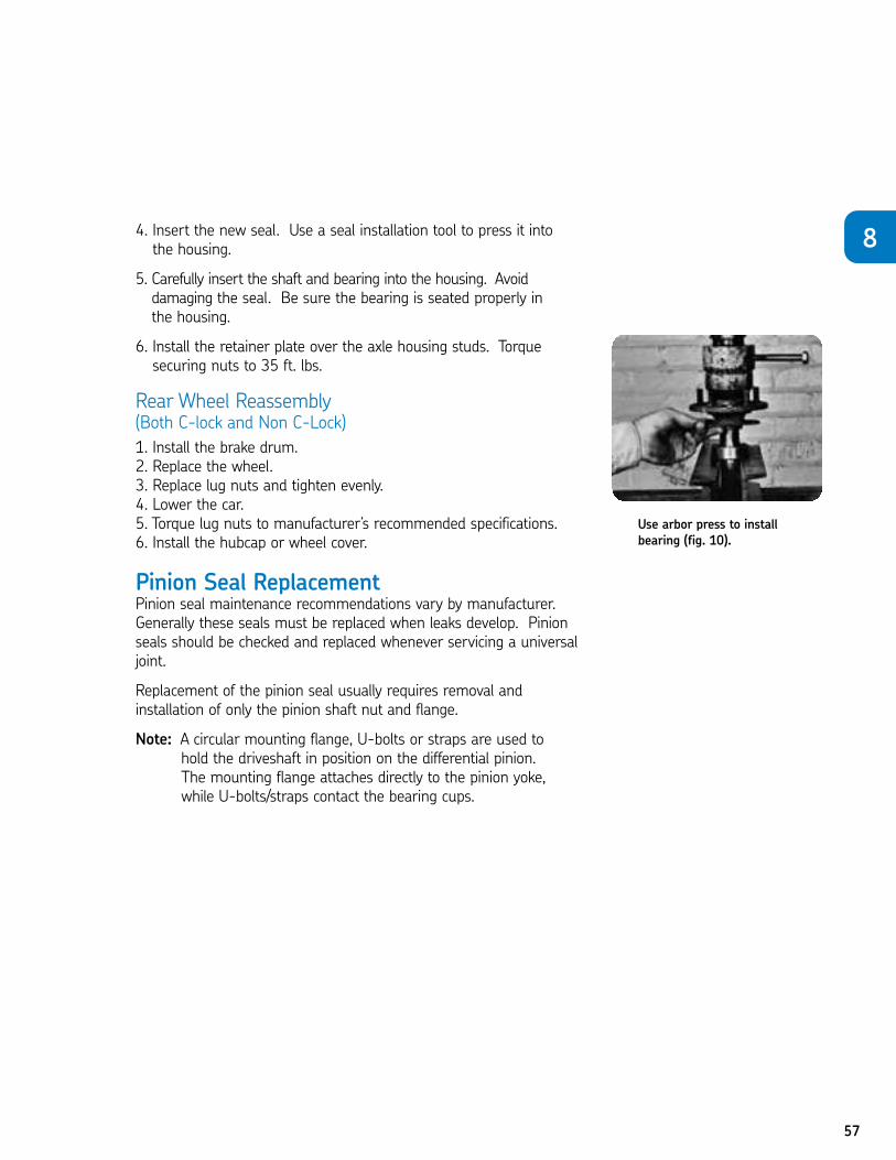
57
4. Insert the new seal. Use a seal installation tool to press it into the housing.
5. Carefully insert the shaft and bearing into the housing. Avoid damaging the seal. Be sure the bearing is seated properly in the housing.
6. Install the retainer plate over the axle housing studs. Torquesecuring nuts to 35 ft. lbs.
Rear Wheel Reassembly (Both C-lock and Non C-Lock)
1. Install the brake drum.2. Replace the wheel.3. Replace lug nuts and tighten evenly.4. Lower the car.5. Torque lug nuts to manufacturer’s recommended specifications.6. Install the hubcap or wheel cover.
Pinion Seal ReplacementPinion seal maintenance recommendations vary by manufacturer.Generally these seals must be replaced when leaks develop. Pinionseals should be checked and replaced whenever servicing a universaljoint.
Replacement of the pinion seal usually requires removal and installation of only the pinion shaft nut and flange.
Note: A circular mounting flange, U-bolts or straps are used to hold the driveshaft in position on the differential pinion. The mounting flange attaches directly to the pinion yoke, while U-bolts/straps contact the bearing cups.
Use arbor press to installbearing (fig. 10).
8
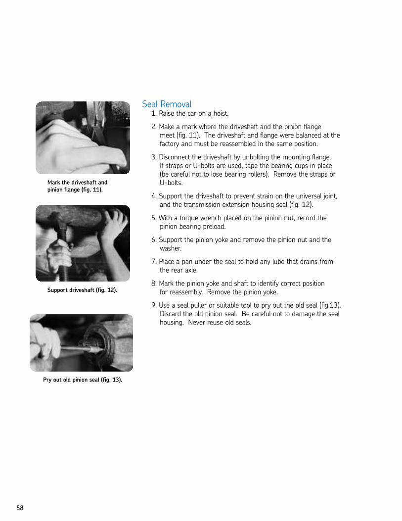
58
Seal Removal1. Raise the car on a hoist.
2. Make a mark where the driveshaft and the pinion flange meet (fig. 11). The driveshaft and flange were balanced at thefactory and must be reassembled in the same position.
3. Disconnect the driveshaft by unbolting the mounting flange. If straps or U-bolts are used, tape the bearing cups in place (be careful not to lose bearing rollers). Remove the straps orU-bolts.
4. Support the driveshaft to prevent strain on the universal joint, and the transmission extension housing seal (fig. 12).
5. With a torque wrench placed on the pinion nut, record the pinion bearing preload.
6. Support the pinion yoke and remove the pinion nut and the washer.
7. Place a pan under the seal to hold any lube that drains fromthe rear axle.
8. Mark the pinion yoke and shaft to identify correct position for reassembly. Remove the pinion yoke.
9. Use a seal puller or suitable tool to pry out the old seal (fig.13).Discard the old pinion seal. Be careful not to damage the sealhousing. Never reuse old seals.
Support driveshaft (fig. 12).
Pry out old pinion seal (fig. 13).
Mark the driveshaft andpinion flange (fig. 11).
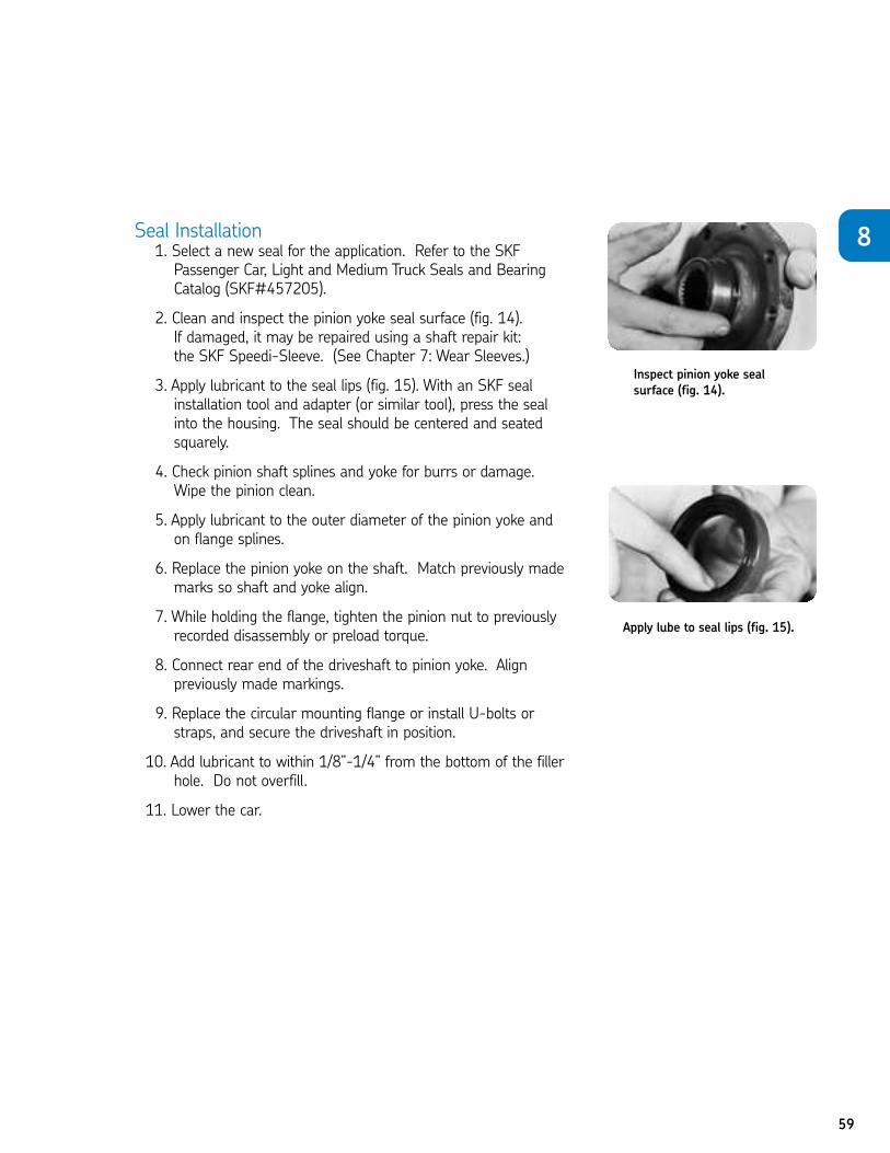
59
Seal Installation1. Select a new seal for the application. Refer to the SKFPassenger Car, Light and Medium Truck Seals and BearingCatalog (SKF#457205).
2. Clean and inspect the pinion yoke seal surface (fig. 14). If damaged, it may be repaired using a shaft repair kit: the SKF Speedi-Sleeve. (See Chapter 7: Wear Sleeves.)
3. Apply lubricant to the seal lips (fig. 15). With an SKF seal installation tool and adapter (or similar tool), press the seal into the housing. The seal should be centered and seatedsquarely.
4. Check pinion shaft splines and yoke for burrs or damage. Wipe the pinion clean.
5. Apply lubricant to the outer diameter of the pinion yoke and on flange splines.
6. Replace the pinion yoke on the shaft. Match previously mademarks so shaft and yoke align.
7. While holding the flange, tighten the pinion nut to previously recorded disassembly or preload torque.
8. Connect rear end of the driveshaft to pinion yoke. Align previously made markings.
9. Replace the circular mounting flange or install U-bolts orstraps, and secure the driveshaft in position.
10. Add lubricant to within 1/8”-1/4” from the bottom of the fillerhole. Do not overfill.
11. Lower the car.
Inspect pinion yoke sealsurface (fig. 14).
Apply lube to seal lips (fig. 15).
8
To take this test, simply place a card or sheet of paper under the first question.After you’ve read it (and answered it to yourself), slide the paper down below thenext question. The correct answer to the first problem will appear directly to theright of the new question. Be sure not to skip any of the questions. This learningtechnique assures more than four times the normal retention rate for even thistechnical subject.
1. Both rear wheels must be elevated when removing rear wheel bearings and seals.
N True N FalseT
2. When performing a seal and/or bearing removal on a “C-lock” type of axleshaft, you do not have to allow the rear axle lubricant to drain.
N True N FalseF
3. After removing a seal from a C-lock axle, you may save it to re-install afterservicing.
N True N FalseF
4. You must replace a bearing if you discover nicks, pitting or damage during inspection.
N True N FalseT
5. When performing service on a Non C-lock axle type shaft, reinstall and finger tighten the lower nuts of the brake backing plate to prevent itfrom slipping off.
N True N FalseT
6. While preparing a C-lock axle shaft for bearing and/or seal installation, there is no need to file or polish nicks or scratches from the axle surface.
N True N FalseF
7. You should use a bearing installation tool to press the new bearing into the axle shaft cavity.
N True N FalseT
8. When installing the retainer plate over the axle housing studs during Non-C-lock installation, be sure to torque the securing nuts to 35 ft. lbs.
N True N FalseT
60
CHAPTER 8 REVIEW
61
9. Replacement of the pinion seal usually requires removal and installation of only the pinion shaft nut and flange.
N True N FalseT
10. During pinion seal removal, there is no need to support the driveshaftto prevent strain on the universal joint.
N True N FalseF
11. Before pinion seal installation, it is important to clean and inspect the pinion yoke seal surface.
N True N FalseT
12. Add lubricant to within 1/8” – 1/4” from the bottom of the filler hole during pinion seal installation, and be sure not to overfill.
N True N FalseT
8
62
FINAL REVIEWCongratulations. You have completed the Pole Position Seals Self-Study
Program. Now you are ready to test your knowledge about SKF seals and Speedi-Sleeves in this Final Exam.First, turn to the last page of this study guide. Remove the Final Review answer
sheet by tearing it out carefully along the perforated edge.Begin the test. Be sure to answer every question; unanswered questions willbe graded as incorrect.
If you have a seal problem that cannot be answered through this study guide,contact your SKF representative. He’s backed by a full crew of technicians—product managers, engineers and service personnel—who will gladly provide the assistance you need.When you have a question, call SKF toll-free: 1-800-882-0008.
01. Seals are used to seal in lubricants and to seal out .N a. dirtN b. waterN c. contaminantsN d. all of the above
02. When the seal’s basic job is to retain, the lip of the seal should facetoward the .
N a. lubricant or pressure being retainedN b. contaminantsN c. both of the aboveN d. neither of the above
03. The acts as a protective cover for the seal.N a. sealing elementN b. outer shellN c. configuration boreN d. auxiliary lip
04. Exclusion seals can be kept lubricated and clear of dirt by .N a. regular cleaningN b. a second sealN c. a special sealing materialN d. purging grease through the lips
63
i05. Packing the cavity between two sealing lips with a grease which cantake the heat generated by the application will .
N a. damage both lipsN b. prolong the life of the auxiliary lipN c. shorten the useful life of the second lipN d. none of the above
06. Nitrile’s only true disadvantage is that it lacks compatibility with .N a. oilN b. abrasionN c. synthetic oilsN d. all of the above
07. A replacement seal manufactured by SKF may have .N a. an SKF stock numberN b. an SKF drawing numberN c. the original equipment manufacturer’s part numberN d. all of the above
08. Silicone’s advantages include .N a. high lubricant absorbencyN b. good flexibility N c. ability to handle a wide temperature range N d. all of the above
09. Fluoroelastomers are recommended for use with special lubricants andchemicals which cannot be handled by .
N a. nitrileN b. polyacrylate N c. silicone N d. all of the above
10. Fluoroelastomer seals have generally replaced as a sealing lip material.N a. siliconeN b. feltN c. leatherN d. all of the above
11. is SKF’s special nitrile compound for extreme abrasion resistance.
N a. Duralip N b. Fluoroelastomer (FKM) N c. Bore-Tite N d. Lexan
64
12. Felt is a non-synthetic material which has long been used as a sealingmaterial. Its advantages include .
N a. excellent water resistanceN b. good exclusion of dust and dirtN c. good tensile strength and abrasion resistanceN d. good oil retention
13. Polyacrylates are elastomers that are compatible with .N a. higher operating temperaturesN b. extreme pressure lubricantsN c. both of the aboveN d. neither of the above
14. is the most popular material for the majority of sealingapplications today.
N a. NitrileN b. Silicone N c. Fluoroelastomer (FKM)N d. Polyacrylate
15. Leather .N a. is toughN b. resists abrasionN c. can usually be replaced with another materialN d. all of the above
16. Nitrile seals will have a short lifespan if the operating temperature is250ºF.
N a. belowN b. aboveN c. atN d. none of the above
17. Choosing the right seal for a particular application depends on .N a. speed and pressureN b. seal dimensions N c. temperature N d. all of the above
18. is the seal’s press-fit diameter, usually .004" to .008" largerthan the bore.
N a. Shaft diameterN b. Seal outside diameterN c. Seal inside diameterN d. None of the above
65
ii19. You should average three measurements of the if the sealis being used to determine shaft diameter.
N a. seal widthN b. seal bore N c. lip inside diameterN d. any of the above
20. Maximum speeds for effective seal performance are affectedby .
N a. operating temperatureN b. the lubricant being retainedN c. pressureN d. all of the above
21. Proper seal installation depends on .N a. the condition of the shaftN b. the condition of the bore N c. use of the right tools and recommended techniquesN d. all of the above
22. is the amount by which the shaft is off center. It is causedby inaccuracies in machining and assembly, or wear in bearings or bushings.
N a. Shaft-to-bore misalignmentN b. Dynamic run-outN c. Shaft speedN d. Shaft balance
23. Shaft finish is critical to proper seal performance. Therefore, .N a. the shaft surface requires machine leadN b. the leading edge must be chamfered or roundedN c. the surface finish should be between 5-7 micro-inchesN d. all of the above
24. If bore finish requirements cannot be met, SKF recommends that a coating ofbe applied to the seal’s outside diameter.
N a. Bore-TiteN b. Fluoroelastomer (FKM)N c. DuralipN d. Lexan
25. To avoid leakage between the seal’s outer diameter and housing, .N a. the bore finish should be approximately 125 micro-inches N b. the inside corners must be coated with Bore-Tite N c. a specific Rockwell hardness must be followed N d. all of the above
66
26. can damage the bearing cage.N a. Prying out the old seal with a rolling head pry barN b. Driving the bearing and seal out with a driftN c. Removing the inner bearing coneN d. All of the above
27. A chisel or screwdriver is for installation.N a. recommendedN b. not recommendedN c. sometimes acceptableN d. none of the above
28. When replacing the seal, inspect the bearing. Bearing cones and cups shouldbe if they are pitted or damaged.
N a. lubricatedN b. replacedN c. rotatedN d. all of the above
29. A light film of prevents rusting on the spindle.N a. Bore-TiteN b. lubricantN c. wax paperN d. powdered metal epoxy type filler
30. A thin-wall coned assembly sleeve is recommended when .N a. the shaft is not tapered N b. a keyway is discovered N c. a spline is presentN d. all of the above
31. Wear patterns of the seal lip may indicate .N a. excessive shaft whip N b. excessive pressure N c. inadequate lubrication N d. all of the above
32. If the seal lip is hardened and brittle with many cracks in its surface,is probably the cause.
N a. pressureN b. eccentricityN c. overheatingN d. a cocked seal
67
iii33. Pressure-caused seal failures can be corrected by .N a. opening air vents which were plugged with dirt or paintN b. replacing the sealN c. reducing operating temperatureN d. all of the above.
34. can cause a seal lip to groove the shaft.N a. Dust, heat and dirtN b. Lack of lubricationN c. A cocked sealN d. All of the above
35. The Speedi-Sleeve® is an ultra-thin wear sleeve made of .N a. bronzeN b. stainless steelN c. zincN d. magnesium
36. The application of a wear sleeve over a damaged surface can .N a. eliminate shaft leaksN b. make the shaft usable againN c. smooth out damaged surfacesN d. all of the above
37. Speedi-Sleeves may be used on .N a. transmissionsN b. crankshaftsN c. pinionsN d. all of the above
38. The inside diameter of a pvc tube used to install a 4 Speedi-Sleeve should be1/32" - 3/16" the shaft.
N a. smaller thanN b. larger thanN c. either of the aboveN d. neither of the above
39. If the shaft is deeply scored, the groove should be .N a. filled with epoxy type fillerN b. filed down to a smooth surface N c. lubricated with oil N d. all of the above
68
40. Whenever a shaft rotates, it needs a bearing and a seal for smooth, effectiveoperation.
N True N False
41. When the seal’s basic job is to exclude, the lip should face away from the contaminants.
N True N False
42. The auxiliary lip on the seal functions only to protect the sealing lip.N True N False
43. The primary lip is the elastomeric component which contacts the rotating surface.
N True N False
44. The garter spring is used for maintaining sealing force between the sealingelement and the shaft.
N True N False
45. Retention seals are recommended for heavy dirt exclusion.N True N False
46. Exclusion/retention seals are two seals combined back-to-back.N True N False
47. Exclusion/retention seals can be kept lubricated and free from dirt by purging,or forcing grease through them.
N True N False
48. Nitrile is recommended with extreme pressure lubes at elevated temperatures.
N True N False
49. Polyacrylates are not available in most general purpose designs.N True N False
50. Silicone’s high lubricant absorbency minimizes friction and wear.N True N False
69
iv51. One fluoroelastomer (FKM) provides superior performance and wear.N True N False
52. In addition to standard materials, SKF can supply seals with elementsmolded of other materials for special conditions.
N True N False
53. PTFE is an expensive material that can be replaced by another lip material.N True N False
54. The SKF Waveseal pumps lubricant back into the sump while sealing outcontaminants, no matter which way the shaft is turning.
N True N False
55. The Waveseal produces less heat, provides better lip lubrication, reducesshaft wear, and wears longer than conventional seals.
N True N False
56. A premium lip material always does a better sealing job than a lessexpensive material.
N True N False
57. Polyacrylates are fluoroelastomers that are compatible with high operatingtemperatures.
N True N False
58. Nitrile is a substitute lip material for leather.N True N False
59. Nitrile is compatible with operating temperatures up to 350ºF.N True N False
60. The seal bore is the diameter of the hole into which the seal will be fitted.N True N False
61. Surface speed at the contact point between the seal and the shaft(fpm: feet per minute) is generally a better indicator of performancethan revolutions per minute (rpm).
N True N False
70
62. Seals perform best on medium carbon steel (SAE 1035 or 1045) orstainless steel shafts.
N True N False
63. Ideally, the shaft should have a finish smooth enough to maintain contactwith the seal lip, but rough enough to hold the lubricant film in place.
N True N False
64. Machine lead marks on the shaft surface will not affect seal performance.N True N False
65. Plunge grinding is the recommended method for finishing the shaft.N True N False
66. Shaft-to-bore misalignment is caused by machining and assembly inaccuracies.
N True N False
67. As shaft speed (rpm) increases, the allowable amount of run-out increases.N True N False
68. Bore hardness must be high enough to maintain interference with the seal’s outside diameter.
N True N False
69. When pre-lubing the lip of the seal, avoid using the lubricant being retained.Two different lubricants should be mixed.
N True N False
70. An arbor press is one of the recommended tools for seal installation.N True N False
71. Replace bearing cups and cones if they are pitted, rough or damaged.N True N False
72. Whatever installation tool is used, the seating force must be applied and spread out over the entire circumference of the seal to avoid distorting the shell.
N True N False
73. It is not necessary to change the seal when the wheel is pulled.N True N False
74. During installation, force should be applied as closely as possible to the outside edge of the seal.
N True N False
71
v75. If a seat is installed into the housing bore with the shaft already installed, use a sleeve-type or hollow fitting tool to protect the lip.
N True N False
76. If a seal lip wears away during normal operation, the seal needs less lubrication.
N True N False
77. Properly installed seals do not have uniform press-fit markings.N True N False
78. Machine lead on the shaft will cause a seal to leak on installation.N True N False
79. Because a seal lip gradually hardens as it ages, it will not remain flexible even if temperatures do not exceed the recommended maximum forthe sealing material.
N True N False
80. Disulfide additives that are used to improve a lubricant’s performance will affect the seal’s performance.
N True N False
81. Installing a seal with a screwdriver or chisel may cause a small nick orcut hardly visible to the eye. This could turn a good seal into a leakerthat should be replaced.
N True N False
82. The installation of a wear sleeve over a shaft is low in cost and requires minimal downtime.
N True N False
83. A Speedi-Sleeve is built with a removable flange and includes a special tool for installation.
N True N False
84. The surface of a Speedi-Sleeve can actually outlast the original shaft surface.N True N False
85. Speedi-Sleeve should be placed over the worn shaft so it is flush with the end of the shaft.
N True N False
72
86. Both rear wheels must be elevated when removing rear wheel bearings and seals.
N True N False
87. When performing a seal and/or bearing removal on a “C-lock” type of axleshaft, you do not have to allow the rear axle lubricant to drain.
N True N False
88. After removing a seal from a C-lock axle, you may save it to re-install afterservicing.
N True N False
89. You must replace a bearing if you discover nicks, pitting or damage during inspection.
N True N False
90. When performing service on a Non C-lock axle type shaft, reinstall and finger tighten the lower nuts of the brake backing plate to prevent itfrom slipping off.
N True N False
91. While preparing a C-lock axle shaft for bearing and/or seal installation, there is no need to file or polish nicks or scratches from the axle surface.
N True N False
92. You should use a bearing installation tool to press the new bearing into the axle shaft cavity.
N True N False
93. When installing the retainer plate over the axle housing studs during Non-C-lock installation, be sure to torque the securing nuts to 35 ft. lbs.
N True N False
94. Replacement of the pinion seal usually requires removal and installation of only the pinion shaft nut and flange.
N True N False
95. During pinion seal removal, there is no need to support the driveshaftto prevent strain on the universal joint.
N True N False
96. Before pinion seal installation, it is important to clean and inspect the pinion yoke seal surface.
N True N False
97. Add lubricant to within 1/8” – 1/4” from the bottom of the filler hole during pinion seal installation, and be sure not to overfill.
N True N False
73
vi
FINAL REVIEWName: Date:
(please print)
Company: Daytime Phone: ( )
Street:(provide complete street address, P.O. Boxes are not accepted)
City: State: Zip:
1. N A N B N C N D
2. N A N B N C N D
3. N A N B N C N D
4. N A N B N C N D
5. N A N B N C N D
6. N A N B N C N D
7. N A N B N C N D
8. N A N B N C N D
9. N A N B N C N D
10. N A N B N C N D
11. N A N B N C N D
12. N A N B N C N D
13. N A N B N C N D
14. N A N B N C N D
15. N A N B N C N D
16. N A N B N C N D
17. N A N B N C N D
18. N A N B N C N D
19. N A N B N C N D
20. N A N B N C N D
21. N A N B N C N D
22. N A N B N C N D
23. N A N B N C N D
24. N A N B N C N D
25. N A N B N C N D
26. N A N B N C N D
27. N A N B N C N D
28. N A N B N C N D
29. N A N B N C N D
30. N A N B N C N D
31. N A N B N C N D
32. N A N B N C N D
33. N A N B N C N D
34. N A N B N C N D
35. N A N B N C N D
36. N A N B N C N D
37. N A N B N C N D
38. N A N B N C N D
39. N A N B N C N D
40. N True N False
41. N True N False
42. N True N False
43. N True N False
44. N True N False
45. N True N False
46. N True N False
47. N True N False
48. N True N False
49. N True N False
50. N True N False
51. N True N False
52. N True N False
53. N True N False
54. N True N False
55. N True N False
56. N True N False
57. N True N False
58. N True N False
59. N True N False
60. N True N False
61. N True N False
62. N True N False
63. N True N False
64. N True N False
65. N True N False
66. N True N False
67. N True N False
68. N True N False
69. N True N False
70. N True N False
71. N True N False
72. N True N False
73. N True N False
74. N True N False
75. N True N False
76. N True N False
77. N True N False
78. N True N False
79. N True N False
80. N True N False
81. N True N False
82. N True N False
83. N True N False
84. N True N False
85. N True N False
86. N True N False
87. N True N False
88. N True N False
89. N True N False
90. N True N False
91. N True N False
92. N True N False
93. N True N False
94. N True N False
95. N True N False
96. N True N False
97. N True N False
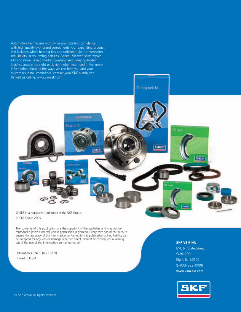
© SKF Group. All rights reserved
® SKF is a registered trademark of the SKF Group.
© SKF Group 2009
The contents of this publication are the copyright of the publisher and may not be reproduced (even extracts) unless permission is granted. Every care has been taken to ensure the accuracy of the information contained in this publication but no liability can be accepted for any loss or damage whether direct, indirect or consequential arising out of the use of the information contained herein.
Publication 457492 (rev 12/09)
Printed in U.S.A.
Automotive technicians worldwide are installing conidence with high quality SKF brand components. Our expanding product line includes wheel bearing kits and unitized hubs, transmission rebuild kits, seals, timing belt kits, Speedi-Sleeve® shaft repair kits and more. Broad market coverage and industry-leading logistics assure the right part, right when you need it. For more information about all the ways we can help you and your customers install conidence, contact your SKF distributor. Or visit us online: www.vsm.skf.com
SKF VSM NA
890 N. State Street
Suite 200
Elgin, IL 60123
1-800-882-0008
www.vsm.skf.com