automobile skill development
TRANSCRIPT

SREE SASTHA INSTITUTE OF ENGINEERING & TECHNOLOGY CHENNAI- BANGALORE HIGHWAY, CHEMBARAMBAKKAM, CHENNAI-123
Phone: 26810114 / 115 / 117 Telefax: 91-44-26810122 E mail : [email protected], / [email protected]
SKILL DEVELOPMENT TRAINING PROGRAM- Training - Study material Name : Roll number .
Branch : Year & section .
The students are expected to attend the class carefully and should observe the demonstration with
interest. Further they must also refer text book and come prepared to have interaction.
Identification of oils
1.Engine oil : Grade :
Mfg Company
Reqd Properties
------------------------------------------------------------------------------------------------------------------
Transmission Oil Grade:
Mfg Company :
Properties
----------------------------------------------------------------------------------------------------
3. Differential and Steering box oil :
Grade:
Mfg Company :
Properties :
-------------------------------------------------------------------------------------------------------
Engine Coolant
Colour :
Chemical used :
Properties :
SREE SASTHA INSTITUTE OF ENGINEERING & TECHNOLOGY CHENNAI- BANGALORE HIGHWAY, CHEMBARAMBAKKAM, CHENNAI-123
Phone: 26810114 / 115 / 117 Telefax: 91-44-26810122 E mail : [email protected], / [email protected]
SKILL DEVELOPMENT TRAINING PROGRAM- Training - Study material
Write the tools used and required for this exercise
1 2 3 4 5
6 7 8 9 10
11 12 13 14 15
16 17 18 19 20
21 22 23 24 25
Write few safety precautions to be followed in the floor/ shop
1.
2
3
4
5
---------------------------------------------------------------------------------------------------------------------------------
Faculty signature :
The engine
The engine parts appearing in the figures on this page have been selected for this discussion because they are representative in most instances of what is considered good automobile-engine design.
No engine could be found which would appeal to all alike as being the accepted standard of good design. Practically every manufacturer holds to certain features which are individual to his product. Minor differences in design may well be lost sight of temporarily. According to the design of the four-stroke-cycle engine, there are a number of parts which are essential to the job no matter who may build it.
For instance, pistons are essential to every engine. There is a vast number of different designs from which good pistons may be built. Just now, it is desirable to show what the piston is, what purpose it serves, its location in the engine, and its relation to other parts of the engine. In the same way, all essential parts of the engine will be considered.

SREE SASTHA INSTITUTE OF ENGINEERING & TECHNOLOGY CHENNAI- BANGALORE HIGHWAY, CHEMBARAMBAKKAM, CHENNAI-123
Phone: 26810114 / 115 / 117 Telefax: 91-44-26810122 E mail : [email protected], / [email protected]
SKILL DEVELOPMENT TRAINING PROGRAM- Training - Study material
Figure 1. Cut sectional view of a single cylinder engine
Cylinder blocks The cylinder block and crankcase casting is the "backbone" of the automobile engine. Besides
furnishing the smooth cylindrical bores for the pistons to slide in, it also serves as a support or mounting for many other parts of the engine.
Cylinder blocks and crankcases are two separate parts of an engine. In this instance they are cast into one piece, this being the usual practice. In some instances, they are made separate. In the latter case, the cylinder block is made from the best grade of cast grey iron and the crankcase from either cast grey iron or cast aluminium alloy. The result of this latter practice is a somewhat lighter engine. In the smaller engines, the difference in weight is not great.
More machine work is required where the two parts are cast separately. This may increase the initial cost. In case of injury to either the crankcase or the cylinder block, however, only the one or the other injured need be purchased for replacement. It frequently happens that a cylinder block is burst by freezing, or is scored, thus necessitating its replacement. Or, a car may be in an accident which results in breaking a leg from the crankcase, and the case has to be replaced. In such instances, there is a distinct
SREE SASTHA INSTITUTE OF ENGINEERING & TECHNOLOGY CHENNAI- BANGALORE HIGHWAY, CHEMBARAMBAKKAM, CHENNAI-123
Phone: 26810114 / 115 / 117 Telefax: 91-44-26810122 E mail : [email protected], / [email protected]
SKILL DEVELOPMENT TRAINING PROGRAM- Training - Study material advantage in having the parts separable. A saving in cost of parts and in labour of replacing them is the result.
Cylinders are cast in blocks. This makes them easier to machine, and gives a rigid engine. These practices are mere matters of manufacturing policy, and have nothing to do with the work which the parts will have to perform. Cylinder blocks exist primarily for the sake of the cylinders. The number of cylinders may be any that the manufacturer decides on, usually four, six, eight, twelve, or sixteen.
Cylinders are machined to a true inner surface. Grinding, boring, reaming, and lapping are machine operations employed to give the desired result. The upper ends of the cylinders are always water jacketed, in the case of water-cooled engines. Valve ports are often set alongside the upper end of the cylinders.
This results in the cylinder block losing the aspect of a group of cylinders, and its outer surface appears in straight lines instead of the curved ones of a cylinder. Cylinders may be equally spaced in the cylinder block, or they may be in groups of two or three. Where only two main bearings are used, the cylinders will be about equally spaced. Where three main bearings are used for the crankshaft, the groups will be two for the four-cylinder engine and three for the six.
Quite frequently, it is desired to place a main bearing between each pair of cylinders, or provide the crankshaft with one more bearing than there are cylinders for the in-line engine. This has the effect of adding a bit to the length of the engine, but it also allows the cylinders to be equally spaced in the block ; and this, in turn, will result in more even cooling since all have approximately the same water-jacketing allowances.
Provision is made at the top of the cylinder block for the water, coming up from the radiator, to pass through holes into the cylinder head. This means, of course, that holes in the cylinder head match the holes in the top of the block.
Crankcases
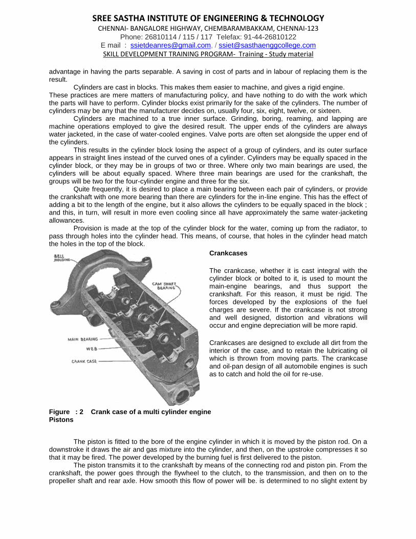
The crankcase, whether it is cast integral with the cylinder block or bolted to it, is used to mount the main-engine bearings, and thus support the crankshaft. For this reason, it must be rigid. The forces developed by the explosions of the fuel charges are severe. If the crankcase is not strong and well designed, distortion and vibrations will occur and engine depreciation will be more rapid.
Crankcases are designed to exclude all dirt from the interior of the case, and to retain the lubricating oil which is thrown from moving parts. The crankcase and oil-pan design of all automobile engines is such as to catch and hold the oil for re-use.
Figure : 2 Crank case of a multi cylinder engine Pistons
The piston is fitted to the bore of the engine cylinder in which it is moved by the piston rod. On a
downstroke it draws the air and gas mixture into the cylinder, and then, on the upstroke compresses it so that it may be fired. The power developed by the burning fuel is first delivered to the piston.
The piston transmits it to the crankshaft by means of the connecting rod and piston pin. From the crankshaft, the power goes through the flywheel to the clutch, to the transmission, and then on to the propeller shaft and rear axle. How smooth this flow of power will be. is determined to no slight extent by

SREE SASTHA INSTITUTE OF ENGINEERING & TECHNOLOGY CHENNAI- BANGALORE HIGHWAY, CHEMBARAMBAKKAM, CHENNAI-123
Phone: 26810114 / 115 / 117 Telefax: 91-44-26810122 E mail : [email protected], / [email protected]
SKILL DEVELOPMENT TRAINING PROGRAM- Training - Study material the design of the piston. Heavy pistons do very well in slow-speed engines. In passenger-car service it is desirable to turn the engines at high speeds.
Figure Cam-ground, aluminum-alloy pistons and chrome-nickel-steel cylinder block
Figure : 3 Sectional view of a Piston Automobile engines were originally figured as delivering their maximum horse power at about
1,000-ft. piston speed per minute. Modern practice of engine building calls for piston speeds in excess of twice this amount. This means that, while travelling (up and down within the cylinder) 2,000 ft. per minute, they are stopped and started in the reverse direction four or five thousand times in the same length of time.
Attention to these two points will enable the student to understand the reason for having the pistons light and properly fitted. If they are not properly fitted, they will either bind on the cylinder walls and score them, or they will be so loose that they will slap the cylinder walls and make a clatter. If too heavy, they will cause vibration. If too light, they will not stand the strains set up by the force of the explosions.

SREE SASTHA INSTITUTE OF ENGINEERING & TECHNOLOGY CHENNAI- BANGALORE HIGHWAY, CHEMBARAMBAKKAM, CHENNAI-123
Phone: 26810114 / 115 / 117 Telefax: 91-44-26810122 E mail : [email protected], / [email protected]
SKILL DEVELOPMENT TRAINING PROGRAM- Training - Study material
Figure : 4 Bore Measurement
The piston alone cannot be designed to seal the cylinder bore so that no gases will leak past it
into the crankcase or oil leak into the combustion space. For this reason, piston rings are used to serve as seals against the loss of compression; that is, the loss of gases past the piston into the crankcase and the prevention of oil being pumped into the combustion area.
Piston rings are made from the best grades of cast iron. They must have a certain springiness or tension so as to expand properly when fitted into the cylinders. At the same time, they may not be so hard that they will wear or score the cylinder walls. The idea uppermost in the minds of the engineers is to have rings which, while making a perfect seal, will continue to give service year after year. As a rule, three or four rings, all above the piston pin, are carried by the piston.
Figure : 5 connecting Rod
Piston pins Piston pins are used to assemble the top end of the connecting rod and the piston with a suitable form of connection. The motion of the pin on its bearings is oscillating (back and forth) and not revolving, as is the case with other engine bearings. Piston pins are made hollow to reduce weight. They are made from steel which is hardened and heat treated. The final machining operation on the pin is grinding it to a mirror like finish and to dimensions which are exact.
Piston-pin locks Locking devices are used tb hold the piston pin secure within the piston, so that the pin may not
work to one side of the piston and thus strike the cylinder wall and score it or groove it. These locking devices may be similar to the screw type, or any one of a number of other forms, one of the most popular being a spring-steel wire, snap ring fitted into the piston-pin bosses at the ends of the pin.

SREE SASTHA INSTITUTE OF ENGINEERING & TECHNOLOGY CHENNAI- BANGALORE HIGHWAY, CHEMBARAMBAKKAM, CHENNAI-123
Phone: 26810114 / 115 / 117 Telefax: 91-44-26810122 E mail : [email protected], / [email protected]
SKILL DEVELOPMENT TRAINING PROGRAM- Training - Study material
Figure : : 6 Piston & Connecting rod assembly
Identify the name of the parts and write
1
2.
3
4
5
6
7
8
9
10

SREE SASTHA INSTITUTE OF ENGINEERING & TECHNOLOGY CHENNAI- BANGALORE HIGHWAY, CHEMBARAMBAKKAM, CHENNAI-123
Phone: 26810114 / 115 / 117 Telefax: 91-44-26810122 E mail : [email protected], / [email protected]
SKILL DEVELOPMENT TRAINING PROGRAM- Training - Study material
Figure : 7. : Observation of Connecting rod
Connecting rods
Material Forged steel Mfg Process : Forging

SREE SASTHA INSTITUTE OF ENGINEERING & TECHNOLOGY CHENNAI- BANGALORE HIGHWAY, CHEMBARAMBAKKAM, CHENNAI-123
Phone: 26810114 / 115 / 117 Telefax: 91-44-26810122 E mail : [email protected], / [email protected]
SKILL DEVELOPMENT TRAINING PROGRAM- Training - Study material
Connecting rods are just what the name signifies. They are rods used to connect the piston with the crankshaft. Properly assembled, they receive the power from the piston and deliver it to the crankshaft. The upper end of the rod moves forth and back, usually in a vertical line, while the lower end is traveling in a circle.
These rods carry the weight of the piston, which must be stopped and started hundreds of times per minute, and bear the strain of compressing the gases within the combustion space and the force of the downward thrust of the exploding gases. When it is remembered that this force may equal a ton in weight, it can be readily seen that no slight strain is to be borne.
Connecting Rod bearings
Material : Whitemetal [ babbit alloy]
The rod bearing, as usually spoken of, is the large split bearing of the connecting rod and that
one which bears on the crank pin. The bearing at the upper end, which carries the piston pin (if in the rod
end), is a bronze bushing. The split bearing is usually formed from Babbitt metal, sweated and cast or
spun into the steel of the connecting rod. Rod bearings are split to allow assembling and disassembling of the rod to the crank pin. This
feature lends itself to ready adjustment of the rod bearings to compensate for wear where the lubrication
design permits. The two halves of the rod bearings are held rigidly together by means of the connecting-
rod bolts. This allows them to be locked to the bolt in such fashion that they will not loosen and allow the
bearings to come out of adjustment. Cotter pins are used to keep the nuts in position. This rod bearing is
fitted with shims for adjustment and is splash lubricated. Rods lubricated by forced pressure seldom use
shims. The lower half of the rod bearing carries grooves within the babbitt lining. These grooves are to
facilitate the oiling of the bearing. The lower half also carries oil dippers or strikers. This is the lowest point
on the rod assembly, and is so designed that it will strike the pool of oil in the crankcase upper-level oil
troughs, and splash it into the rod bearing and onto other parts of the engine needing lubrication. The upper halves are grooved similarly to the lower halves, and holes are drilled through them
and on through the rod metal so as to provide oil-feed holes on the top of the bearing. Shims
Rod-bearing shims appear on the bolts of the rod. These are made of brass, as a rule. They may be solid, or they may be built up from a number of pieces of very thin brass. Such shims are termed "laminated" shims. In some cases shims are not provided by the manufacturer.
The purpose of shims is to give a ready means of adjusting bearings. By taking out a very thin shim, the bearings may come closer together, and thus space allowed by wear is taken up. This is the reason that the process of fitting bearings is often spoken of as "taking up bearings."
Where no shims are provided by the manufacturer, it is necessary to drawfile or otherwise reduce the cheeks of the bearing cap in the taking-up process. This practice is not recommended for pressure-lubricated bearings as the bearing is then out-of-round and oil is lost at the sides.
Crankshafts
Material : Forged steel Mfg Process : Forging
The journals are ground to mirror finish and hardened by heat treatment called NITRIDING.Nitriding takes about 36 hrs.

SREE SASTHA INSTITUTE OF ENGINEERING & TECHNOLOGY CHENNAI- BANGALORE HIGHWAY, CHEMBARAMBAKKAM, CHENNAI-123
Phone: 26810114 / 115 / 117 Telefax: 91-44-26810122 E mail : [email protected], / [email protected]
SKILL DEVELOPMENT TRAINING PROGRAM- Training - Study material
Crankshafts, as used in modern cars, are the result of most careful designing and engineering. They are called on to receive great loads and transmit much power. They must do this while turning at high speeds and slow speeds. They must literally float in a bath of oil within the bearings. This means that they must be machined with extreme accuracy. They must have smooth journals for the soft babbitt metal to carry them without harm. A cylinder at the front of the engine fires, and then one toward the rear.
Figure : 8 : Crank shaft
The shaft has a great force exerted on it, first at its front end and then at the rear, another at the
front end, and another at the rear, and so on. This means that the shaft has to resist the bending and
twisting strains set up. It must not spring out of true, or it will whip out the bearings. Being so irregular in
shape, it presents difficulties in machining. The art of building and balancing crankshafts has been carried forward to a point where it is rare
indeed that one fails. Shafts may wear, but they seldom are broken. They may be sprung out of line
owing to bad bearing adjustment or other cause, but such trouble is rare. The steel used in crankshafts is special stock. Not all companies use the same grades of steel.
Many shafts are nickel steel, and many others are vanadium steel. Some shafts used in the Ford V-8 are
a special grade of cast steel. They have bearing surfaces of greater degree of hardness and are lighter
than the forged steel shafts.
Manufacturers specify the formula to the steel makers in many instances so that the shaft may
have the exact qualities of strength and hardness which they wish when it has been machined, heat-treated, and finished. Figure illustrates a shaft for an eight-cylinder job having nine main bearings.

SREE SASTHA INSTITUTE OF ENGINEERING & TECHNOLOGY CHENNAI- BANGALORE HIGHWAY, CHEMBARAMBAKKAM, CHENNAI-123
Phone: 26810114 / 115 / 117 Telefax: 91-44-26810122 E mail : [email protected], / [email protected]
SKILL DEVELOPMENT TRAINING PROGRAM- Training - Study material
measurements Figure : 10 : Crankshaft Maesurements Obsevation
Camshafts
Material : Forged steel Mfg Process : Forging
Figure illustrates a camshaft and related parts. Three bearing journals appear on the camshaft. These are made large in order that the shaft may be slipped into its bearings from the end. In other words, the bearing journals are larger than the cams.

SREE SASTHA INSTITUTE OF ENGINEERING & TECHNOLOGY CHENNAI- BANGALORE HIGHWAY, CHEMBARAMBAKKAM, CHENNAI-123
Phone: 26810114 / 115 / 117 Telefax: 91-44-26810122 E mail : [email protected], / [email protected]
SKILL DEVELOPMENT TRAINING PROGRAM- Training - Study material
Figure : 11. Camshaft and drive assembly
Camshafts turn at half engine speed, with the valve lifter riding on the cam. When lifting a valve at high speed against the spring tension and the force of the exploding gases the load is not light. If valves are not set properly with regard to stem clearance, the camshaft may have to bear the force of an explosion on the top of the valve head. Special steels, which lend themselves to heat treating, are used.
The faces of the cams are always hardened, as the constant wear caused by the sliding or rolling action
of the valve lifters would otherwise wear them rapidly. As suggested previously, there are two valves and
consequently two cams per cylinder, except in rare cases of special design.
Valve lifters and valve-lifter guides
Figure above shows the valve lifters and valve-lifter guides. These appear above the camshaft, in
a position similar to the one occupied in the assembled engine. When assembled, the lifter guides are
locked in position by means of the straps, which are shown in position on the two left-hand pairs of lifter
guides. The guides are of cast iron and are machined on their outer surfaces to fit the cylinder block. The inside of the guide is machined to receive the lifter or, as it is frequently called, the tappet. The
fit is free-sliding, but not loose. The tappets are made of steel which may be hardened. They carry in their
upper end a set screw called the valve-lifter adjusting screw. This screw is used to give an adjustment of
the valve-stem clearance when the valve is closed. After adjustments are made, they are secured by
means of the lock nut. Timing gears Engines must operate in time. Time means that the crankshaft speed, which is called engine
speed, will be just twice that of the camshaft, which is spoken of as camshaft speed. This means that
there are twice the number of teeth in the camshaft gear compared to those provided for the crankshaft
gear.

SREE SASTHA INSTITUTE OF ENGINEERING & TECHNOLOGY CHENNAI- BANGALORE HIGHWAY, CHEMBARAMBAKKAM, CHENNAI-123
Phone: 26810114 / 115 / 117 Telefax: 91-44-26810122 E mail : [email protected], / [email protected]
SKILL DEVELOPMENT TRAINING PROGRAM- Training - Study material
It is not only necessary that the gears (or sprockets in the case of chain drive) have a ratio of 2 to 1, but they must be so arranged that they may be assembled according to marks and have the engine operate in proper valve time. It will be noted that there are marks on the gears.
The small gear has an 0 on one tooth which meshes between two teeth on the large gear marked 00. Marks used by manufacturers vary, but their purpose is the same. Owing to the fact that a chain drive offers certain advantages, it is used in many instances. However, the requirements are the same in every case of four-cycle motors. Figure illustrates a chain and sprocket drive. The correct timing is indicated by having the correct number of teeth between, the two O's on the sprockets.
Figure : 12 : Chain drive mechanism
Valves
Valves and their operation have occasioned much discussion and experimentation among the builders of motor cars. Many types of valves have been developed to facilitate the admission of gases to the combustion space and their expulsion from the combustion space.
Figure : 13 Valve assembly
The most commonly known and used is the type illustrated. This is known as the poppet type. It may be operated with a rocker arm on the top of the engine, with a camshaft on the top of the engine, or directly by means of the lifters as shown herewith. The double-sleeve valve, single-sleeve valve, and rotary valve are in limited use. As a rule, the poppet type of valve is lifted directly by the cam on the camshaft or by push-rod and rocker-arm action. It is returned to its seat by means of the valve springs.
The valves from a four-cylinder engine, together with the springs, the cups, and the retaining pins, appear laid out in order in, figure. Here, as in the case of the rod and main bearings, care must be used to maintain order. The valve from the exhaust port of cylinder Number 1 is considered valve Number 1, and is usually so marked. Intake valve for cylinder Number 1 is usually valve 2, and so on, numbering in order from the front to the rear of the engine. Some manufacturers do not number valves.

SREE SASTHA INSTITUTE OF ENGINEERING & TECHNOLOGY CHENNAI- BANGALORE HIGHWAY, CHEMBARAMBAKKAM, CHENNAI-123
Phone: 26810114 / 115 / 117 Telefax: 91-44-26810122 E mail : [email protected], / [email protected]
SKILL DEVELOPMENT TRAINING PROGRAM- Training - Study material
Figure 14 : Nomenclature of a Valve
Valves are made from special heat-resisting steels, such as tungsten, and the rustles- or stainless-steel alloys. The valve serves the purpose of sealing the cylinder on the compression and power strokes. At the end of the power stroke, the exhaust valve rises and allows the burned gases to be pushed past it into the exhaust port and manifold. At the end of the exhaust stroke, the intake valve rises and allows the new fuel charge to be drawn in.
Mention and identify the parts of the valve mechanism
Inlet valve : NIChrome steel Exhaust valve : SilChrome Steel

SREE SASTHA INSTITUTE OF ENGINEERING & TECHNOLOGY CHENNAI- BANGALORE HIGHWAY, CHEMBARAMBAKKAM, CHENNAI-123
Phone: 26810114 / 115 / 117 Telefax: 91-44-26810122 E mail : [email protected], / [email protected]
SKILL DEVELOPMENT TRAINING PROGRAM- Training - Study material
Figure : 15 ; OHC Mechanism
Each valve for a cylinder is operated once for two turns of the crankshaft. The lift on a valve is about 5/16 in. to in. The heat of the burning gases burns and warps the valves. The valve stems are worn because the heat destroys the oil. Carbon and soot gather on them. Continual pounding wears the face where it seats. Their proper care means periodic cleaning and grinding. In figure appear all of the essential moving parts of an engine. These parts are assembled in this skeleton form in order to make their interrelation clearer. Timing gears are in position and meshed.
One piston appears on throw Number 1. Cams carry valves 7 and 8 on their lifters in natural position. When assembled within the engine, the parts are in approximately the same position as seen in this picture. However, after assembling the parts, it is impossible to see their exact relation.
Engine bearings
Engine bearings were mentioned previously. These caps carry the bearings proper. The soft babbitt metal is sweated into the bronze back which is a perfect fit for the cap.
Flywheels
A study of the engine involves consideration of the purposes which the engineers have designed the flywheel to serve. Without a flywheel, it would be almost impossible to start an engine. It would run irregularly if at all. The flywheel has weight. This serves to steady the motion of the crankshaft, and keeps it turning evenly.
The weight of the flywheels in use in passenger vehicles varies from fifteen or twenty pounds up to almost a hundred pounds, depending on the task assigned to the part by the designer of the engine. Engines may have counterbalances attached to the crankshafts. These serve the purpose desired of storing energy and giving it off to keep the engine turning evenly. Some engines are fitted with vibration dampeners in the form of small flywheels on the forward end of the crankshaft, to secure smooth operation.
The greater number of cylinders provided, the less weight it is necessary to give the flywheel. The operating speed of the engine has a great deal to do with this. The engine which operates at a slow speed under heavy load requires a heavier flywheel than the engine which carries a light load and is built for quick pickup.

SREE SASTHA INSTITUTE OF ENGINEERING & TECHNOLOGY CHENNAI- BANGALORE HIGHWAY, CHEMBARAMBAKKAM, CHENNAI-123
Phone: 26810114 / 115 / 117 Telefax: 91-44-26810122 E mail : [email protected], / [email protected]
SKILL DEVELOPMENT TRAINING PROGRAM- Training - Study material
Some engines are constructed with two flywheels, one at either end of the shaft. Airplane engines use the spinning propeller to help in this function of giving an even operating speed and carry no flywheel. Another function commonly allotted to the flywheel is to serve as a mounting for the ring gear which is used to turn the engine over for cranking. Sometimes the teeth are cut directly into the face of the wheel. This gives a gear somewhat subject to breakage and wearing away. Better practice specifies the mounting of a steel ring on the cast-iron flywheel.
Figure : 16 Flywheel
The flywheel is mounted onto the crankshaft flange by means of heavy bolts. These must be drawn quite tight in order that there may not be any rocking of the flywheel on its mounting. Some manufacturers machine the mounting holes so that it is impossible to mount the flywheel in any but the original position.
This serves to keep the flywheel markings correct and, if the flywheel has been balanced in connection with the shaft, it serves to maintain that balance. The centre of the flywheel is usually arranged to carry the small ball bearing used to support the forward end of the clutch shaft.
The further function of the flywheel is to carry the clutch. In most instances, the flywheel web is machined to a flat surface, and is used as a bearing surface to receive the clutch facing. It thus acts as one of the driving surfaces. Clutches are frequently bolted, in their entirety, to the rim of the flywheel which acts as a housing for them.
Timing-gear covers
The covers for the timing gears are arranged for ready removal in practically all makes of modern passenger automobiles. This is done to make easy the complete inspection of the gears or chain, or their replacement in case of wear or injury.
Cylinder heads
Cylinder heads are made removable. The head may cover all cylinders, or several heads may be used to cover one block. The head shown, along with the spark plug, is of the non-detonating design for L-head motors. Water is taken into the head from the holes in its machined face, rises around the plugs, and is taken off to the radiator through the pipe like part of the casting which serves for a hose connection. Where valve-in-the-head or overhead valves are used, they are mounted in the cylinder head.

SREE SASTHA INSTITUTE OF ENGINEERING & TECHNOLOGY CHENNAI- BANGALORE HIGHWAY, CHEMBARAMBAKKAM, CHENNAI-123
Phone: 26810114 / 115 / 117 Telefax: 91-44-26810122 E mail : [email protected], / [email protected]
SKILL DEVELOPMENT TRAINING PROGRAM- Training - Study material
Removing the head removes the entire set of valves with the rocker arms. The camshaft, except in overhead-cam construction, remains in the conventional point next to the crankshaft in the crankcase. The valve lifters, for valve-in-head motors, push on push rods instead of valve stems, and rocker arms are required to reverse the direction of motion and force the valves downward.
Figure : 17 Cylinder Head
Oil pans
The oil pan forms the lower half of the crankcase. General practice stipulates pressed-sheet-metal pans, but they may be of cast aluminium. The lower level is what is termed the sump. Here the oil is stored. From the sump, oil is pumped to the upper pan or oil level and to all parts requiring lubrication by pressure. Oil pumps are frequently carried in the oil pan.
The oil-level indicator is fitted to the crankcase and pan. Oil pans must be rigid, but need not have great strength. They are assembled to the lower part of the crankcase upper half by means of bolts or cap screws. Gaskets are used in the joint to make it oil tight. In cases of full-force feed, the oil sump may be covered with a screen at a point about that of the second level. Full-force-feed lubrication requires no individual troughs for the rods to dip into.
Manifolds
Manifolds are used to conduct gases into or out of an engine. The carburetor may be either updraft or downdraft. In either case it attaches to a flange cast onto the intake manifold.
The design of intake and exhaust manifolds depends on the number of cylinders of the engine and whether it is a line engine or a V-type engine. Sometimes they are cast separate and at other times integral. In many designs the heat given off by the exhaust gases as they travel from the engine is used to heat up the incoming gases through the dividing walls of the intake and exhaust-manifold casting.
Oil pumps
Oil pumps are an integral part of most engines. Pumps are used to lift the oil from the sump to the upper level in the splash and circulating system and, in the forced feed, they pump the oil to the tubes or lines leading to the bearings and other parts of the engine. The drive of the oil pump is usually by means of a gear on the crankshaft.
Water Pumps
Most water-cooled engines carry water pumps. Smaller engines may depend on thermosiphon circulation. Pumps may be driven from gears or chain in the timing-gear case, in which case the shaft is termed the pump shaft or accessory shaft. The pump shaft is extended through the pump in most
SREE SASTHA INSTITUTE OF ENGINEERING & TECHNOLOGY CHENNAI- BANGALORE HIGHWAY, CHEMBARAMBAKKAM, CHENNAI-123
Phone: 26810114 / 115 / 117 Telefax: 91-44-26810122 E mail : [email protected], / [email protected]
SKILL DEVELOPMENT TRAINING PROGRAM- Training - Study material instances where this drive is used, and it is then used to drive some other accessory as, for instance, the magneto, timer-distributor, or the generator.
Pumps are frequently placed on the cylinder-block front end in connection with the fan drive or the generator drive, when it is mounted at the front of the cylinder block. When pumps are used, circulation is forced, and the water lines are smaller than when thermosiphon circulation is used.
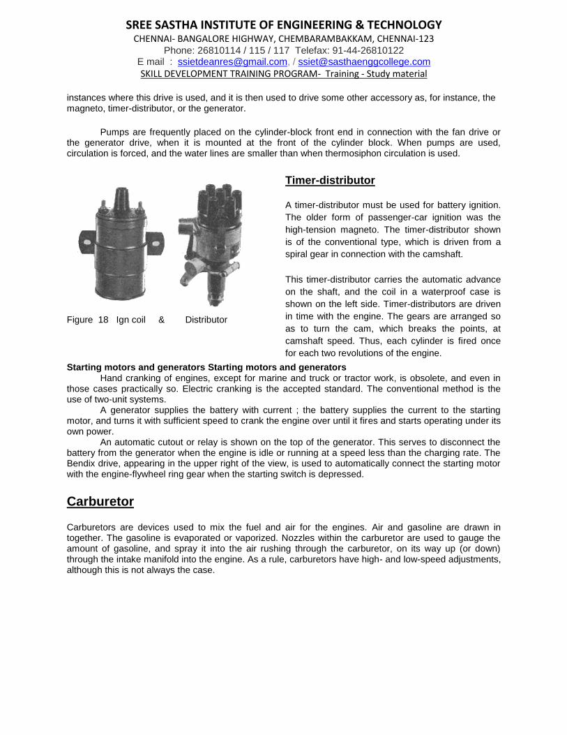
Figure 18 Ign coil & Distributor
Timer-distributor
A timer-distributor must be used for battery ignition.
The older form of passenger-car ignition was the
high-tension magneto. The timer-distributor shown
is of the conventional type, which is driven from a
spiral gear in connection with the camshaft.
This timer-distributor carries the automatic advance
on the shaft, and the coil in a waterproof case is
shown on the left side. Timer-distributors are driven
in time with the engine. The gears are arranged so
as to turn the cam, which breaks the points, at
camshaft speed. Thus, each cylinder is fired once
for each two revolutions of the engine.
Starting motors and generators Starting motors and generators Hand cranking of engines, except for marine and truck or tractor work, is obsolete, and even in
those cases practically so. Electric cranking is the accepted standard. The conventional method is the use of two-unit systems.
A generator supplies the battery with current ; the battery supplies the current to the starting motor, and turns it with sufficient speed to crank the engine over until it fires and starts operating under its own power.
An automatic cutout or relay is shown on the top of the generator. This serves to disconnect the battery from the generator when the engine is idle or running at a speed less than the charging rate. The Bendix drive, appearing in the upper right of the view, is used to automatically connect the starting motor with the engine-flywheel ring gear when the starting switch is depressed.
Carburetor
Carburetors are devices used to mix the fuel and air for the engines. Air and gasoline are drawn in together. The gasoline is evaporated or vaporized. Nozzles within the carburetor are used to gauge the amount of gasoline, and spray it into the air rushing through the carburetor, on its way up (or down) through the intake manifold into the engine. As a rule, carburetors have high- and low-speed adjustments, although this is not always the case.

SREE SASTHA INSTITUTE OF ENGINEERING & TECHNOLOGY CHENNAI- BANGALORE HIGHWAY, CHEMBARAMBAKKAM, CHENNAI-123
Phone: 26810114 / 115 / 117 Telefax: 91-44-26810122 E mail : [email protected], / [email protected]
SKILL DEVELOPMENT TRAINING PROGRAM- Training - Study material
Figure : 19 Cut sectional view Carburetor
PROGRESSIVE STARTER. Ga Air jet. Gs Petrol jet. b Starter channel. 01/02 Starter feed tracts. C Starter piston. E Starter air bleed.
MAIN CARBURETTOR. a Air correction jet. K Choke tube. s Emulsion tube. Gg Main jet. Y Main jet holder. u Pilot jet air bleed. g Pilot jet. W Volume control screw. V Throttle butterfly F Float
ACCELERATING & ECONOMY DEVICE. r Pump spring. d Depression channel. M & Mm Membranes. H Pump ball valve. ci Ball valve (inlet). ca Injector calibration. i Injector tube. Gu Economy jet l Pump Lever e Rod adjustment nut
Figure Solex for ROVER P3

SREE SASTHA INSTITUTE OF ENGINEERING & TECHNOLOGY CHENNAI- BANGALORE HIGHWAY, CHEMBARAMBAKKAM, CHENNAI-123
Phone: 26810114 / 115 / 117 Telefax: 91-44-26810122 E mail : [email protected], / [email protected]
SKILL DEVELOPMENT TRAINING PROGRAM- Training - Study material
Figure : 20 Double venture Carburettor
Candidates must identify and write the names of the parts :

SREE SASTHA INSTITUTE OF ENGINEERING & TECHNOLOGY CHENNAI- BANGALORE HIGHWAY, CHEMBARAMBAKKAM, CHENNAI-123
Phone: 26810114 / 115 / 117 Telefax: 91-44-26810122 E mail : [email protected], / [email protected]
SKILL DEVELOPMENT TRAINING PROGRAM- Training - Study material Many carburetors have but one adjustment. The one illustrated has high- and low-speed adjustments besides the choke, on the incoming air passage. Automobile engines must be throttled to control the driving speed. This operation requires a rather complicated carbureting device, to insure the proper mixture of fuel and air for the varying speeds and loads of the motor.
Fans
Figure illustrates a fan. Fans may be carried on plain bearings or on ball or roller bearings. The fan pulley appears with the fan. Fans are driven from the camshaft, from the crankshaft, or, as in this instance, from the pump shaft.
Figure : 21 Water pump
The purpose of the fan is to create a draft of air through the radiator, in order that it may carry off the heat from the water which has brought the heat to the radiator from the engine. Passenger cars carry rather light fans, trucks carry heavier fans, and tractors have still heavier fans.
The speed at which the engine is carried forward through the atmosphere has much to do with the need of fan circulation of the air. Racing cars require no fans, since they are thrust forward at such a rate that a fan might hinder the circulation of the air rather than help it.
Gaskets
In all engine work and in many other cases, in assembling machined parts which must be free from compression leaks and oil leaks, the practice is to use gaskets of some form or other. Gaskets are made up from soft, semi-soft, or plastic materials.
Figure 22 : gaskets

SREE SASTHA INSTITUTE OF ENGINEERING & TECHNOLOGY CHENNAI- BANGALORE HIGHWAY, CHEMBARAMBAKKAM, CHENNAI-123
Phone: 26810114 / 115 / 117 Telefax: 91-44-26810122 E mail : [email protected], / [email protected]
SKILL DEVELOPMENT TRAINING PROGRAM- Training - Study material
Cylinder-head gaskets are usually made from two sheets of copper or brass with a sheet of
asbestos between. Many other gaskets are of this construction which is termed copper-asbestos-gasket
construction. Exhaust-manifold gaskets are made from a specially constructed material which embodies
copper wires, asbestos, and graphite. Some gaskets are formed over sheet-metal grids as a support for
the softer materials.
Many gaskets are of cork, many are of felt, and many are of ordinary paper or cardboard. Special
gasket materials are marketed. The student mechanic soon learns to cut his own gaskets where paper or
the commoner materials are used.
Oil Pump The type of pump used varies. Gear pumps[1][2] trochoid pumps[3] and vane pumps[note 1]are all
commonly used. Plunger pumps have been used in the past, but these are now only used rarely, for small engines.
To avoid the need for priming, the pump is always mounted low-down, either submerged or around the level of the oil in the sump. A short pick-up pipe with a simple wire-mesh strainer reaches to the bottom of the sump.
Rotar type
Gear Pump
Figure : 23 ; Oil pump
Water Pump
The water pump is a simple centrifugal pump driven by a belt connected to the crankshaft of the engine. The pump circulates fluid whenever the engine is running. The water pump uses centrifugal force to send fluid to the outside while it spins, causing fluid to be drawn from the center continuously. The inlet to the pump is located near the center so that fluid returning from the radiator hits the pump vanes. The pump vanes fling the fluid to the outside of the pump, where it can enter the engine. The fluid leaving the pump flows first through the engine block and cylinder head, then into the radiator and finally back to the pump.
Its body is made of CI /Cast Al. and nowadays the impellor is made of noncorrosive metal/nonmetal

SREE SASTHA INSTITUTE OF ENGINEERING & TECHNOLOGY CHENNAI- BANGALORE HIGHWAY, CHEMBARAMBAKKAM, CHENNAI-123
Phone: 26810114 / 115 / 117 Telefax: 91-44-26810122 E mail : [email protected], / [email protected]
SKILL DEVELOPMENT TRAINING PROGRAM- Training - Study material
Figure : 24 Water Cooling System and water pump sectional view
MEASUREMENT OF THE PROFILE OF THE WATERPUMP
Universal coupling
A universal joint, universal coupling, U-joint, Cardan joint, Hardy-Spicer joint, or Hooke's joint is
a joint or coupling in a rigid rod that allows the rod to 'bend' in any direction, and is commonly
used in shafts that transmit rotary motion. It consists of a pair of hinges located close together,
oriented at 90° to each other, connected by a cross shaft.
Figure : 25 Universal joint

SREE SASTHA INSTITUTE OF ENGINEERING & TECHNOLOGY CHENNAI- BANGALORE HIGHWAY, CHEMBARAMBAKKAM, CHENNAI-123
Phone: 26810114 / 115 / 117 Telefax: 91-44-26810122 E mail : [email protected], / [email protected]
SKILL DEVELOPMENT TRAINING PROGRAM- Training - Study material
Figure : 26 : exploded view of an Universal Coupling
Study and use the following tools and write your observation
1. Feeler gauge
2. Plate Thickness gauge
3. Wire gauge
4. Torque wrench
5. Feeler gauge
6.
Part 2.- Drafting & Design

SREE SASTHA INSTITUTE OF ENGINEERING & TECHNOLOGY CHENNAI- BANGALORE HIGHWAY, CHEMBARAMBAKKAM, CHENNAI-123
Phone: 26810114 / 115 / 117 Telefax: 91-44-26810122 E mail : [email protected], / [email protected]
SKILL DEVELOPMENT TRAINING PROGRAM- Training - Study material
The students / trainees will have to model the shapes of the parts in 2D and 3D. The
students have already recorded the measurements /observations in the logbook . All
efforts should be taken to measure the profile of the given part/equipment
With the available measuring instrument.
Important Steps of Designing Machine
Though the machine design procedure is not standard, there are some common steps to be followed; these can be followed as per the requirements wherever and whenever necessary. Here are some guidelines as to how the machine design engineer can proceed with the design:
1) Making the written statement: Make the written statement of what exactly is the
problem for which the machine design has to be done. This statement should be
very clear and as detailed as possible. If you want to develop the new produce
write down the details about the project. This statement is sort of the list of the
aims that are to be achieved from machine design.
2) Consider the possible mechanisms: When you designing the machine consider all the
possible mechanisms which help desired motion or the group of motions in your
proposed machine. From the various options the best can be selected whenever required.
3) Transmitted forces: Machine is made up of various machine elements on which various
forces are applied. Calculate the forces acting on each of the element and energy
transmitted by them.
4) Material selection: Select the appropriate materials for each element of the machine so
that they can sustain all the forces and at the same time they have least possible cost.
5) Find allowable stress: All the machine elements are subjected to stress whether small or
large. Considering the various forces acting on the machine elements, their material and
other factors that affect the strength of the machine calculate the allowable or design
stress for the machine elements.
6) Dimensions of the machine elements: Find out the appropriate dimensions for the
machine elements considering the forces acting on it, its material, and design stress. The
size of the machine elements should be such that they should not distort or break when
loads are applied.
7) Consider the past experience: If you have the past experience of designing the machine
element or the previous records of the company, consider them and make the necessary

SREE SASTHA INSTITUTE OF ENGINEERING & TECHNOLOGY CHENNAI- BANGALORE HIGHWAY, CHEMBARAMBAKKAM, CHENNAI-123
Phone: 26810114 / 115 / 117 Telefax: 91-44-26810122 E mail : [email protected], / [email protected]
SKILL DEVELOPMENT TRAINING PROGRAM- Training - Study material
changes in the design. Further, designer can also consider the personal judgment so as to
facilitate the production of the machine and machine elements.
8) Make drawings: After designing the machine and machine elements make the assembly
drawings of the whole machines and detailed drawings of all the elements of the
machine. In the drawings clearly specify the dimensions of the assembly and the machine
elements, their total number required, their material and method of their production. The
designer should also specify the accuracy, surface finish and other related parameters for
the machine elements.

SREE SASTHA INSTITUTE OF ENGINEERING & TECHNOLOGY CHENNAI- BANGALORE HIGHWAY, CHEMBARAMBAKKAM, CHENNAI-123
Phone: 26810114 / 115 / 117 Telefax: 91-44-26810122 E mail : [email protected], / [email protected]
SKILL DEVELOPMENT TRAINING PROGRAM- Training - Study material
DISCLAIMER The information contained in this is for skill training for Mechanical and automobile engineering third year students purpose sonly.
We thank all those who have rendered the sources of information directly or indirectly in compiling the material. The training is aimed to understand the basics. The information is provided by and while we endeavour to keep the information up to date and correct, we make no representations or warranties of any kind, express or implied, about the completeness, accuracy, reliability, suitability or availability with respect to the website or the information, products, services, or related graphics contained on the website for any purpose. Any reliance you place on such information is therefore strictly at your own risk.
In no event will we be liable for any loss or damage including without limitation, indirect or consequential loss or damage, or any loss or damage whatsoever arising from loss of data or profits arising out of, or in connection with, the use of this website.
We have no control over the nature, content and availability of those sites. The inclusion of any links does not necessarily imply a recommendation or endorse the views expressed within them.
However, We take no responsibility for, and will not be liable for, any technical issues beyond our control.