automationml e.v. office nicole schmidt, arndt lüder state
TRANSCRIPT

AutomationML in a Nutshell
AutomationML e.V. Office
Nicole Schmidt, Arndt Lüder
State: November 2015

AutomationML in a Nutshell
2
AutomationML in a Nutshell
3
Abstract
The world of production systems is at a turning point. Increasing importance of customer needs and increasing speed of technological progress affect production system owners to increase production system flexibility related to product portfolio and resource utilisation [1]. But this increase of flexibility is not that easy to reach. New ways of production systems engineering and use are required as envisioned in the Industrie 4.0 approach [2] and [3].
Industrie 4.0 envisions an increased integration in many direction related to production systems. It considers the integration of different life cycle phases of production systems, the integration along the different layers of control ranging from field control to company networks, and the integration along the engineering chain of production systems, i.e. the chain of engineering activities executed by engineers with appropriate engineering tools.
Increased flexibility requires a higher frequency of engineering activities (design and redesign). Thus, engineering gets more important in the production system life cycle as its time and cost share in the production system life cycle increases. The integration of engineering activities and their involved tools along the engineering chain shall be one mean to reduce engineering time and costs by preventing unnecessary replication of engineering activities, increased continuity of engineering tool chains, and improved cooperation of engineers (to name only a few expected effects).
One means to enable the integration of engineering activities and tools along engineering chains of production systems and, additionally, to enable the application of engineering data within the use phase of a production system is an appropriate date exchange format. Following the roadmap of Industrie 4.0 such a data format has to be developed. Within this paper the data exchange format AutomationML is considered. The range of data representation of AutomationML is sketched to enable a judgement whether AutomationML can be a candidate for implementation of integration within the engineering chain of production systems following the Industrie 4.0 approach or not.
©AutomationML consortium
November 1st
2015
Contact: www.automationml.org

AutomationML in a Nutshell
4
AutomationML in a Nutshell
5
Content 1 Introduction .................................................................................................................................. 6 2 Covered Engineering Processes and Engineering Data ............................................................. 7 3 Running Example ....................................................................................................................... 11 4 General Architecture of AutomationML ...................................................................................... 12 5 System Topology and System Element Modelling .................................................................... 14 6 Integration of Object Semantics ................................................................................................. 21 7 Geometry and Kinematics .......................................................................................................... 24 8 Behaviour Modelling ................................................................................................................... 27 9 Modelling of Networks ................................................................................................................ 29 10 Integration of Further External Information ................................................................................ 35 11 Application Process .................................................................................................................... 36 12 Conclusions ................................................................................................................................ 38 Literature .............................................................................................................................................. 39
AutomationML in a Nutshell
6
1 Introduction
The engineering of production systems is a complex process involving several engineers of several engineering disciplines executing several engineering activities and using / creating several engineering artefacts required to finally be able to build up, run, and maintain a production system [1].
As different investigations have shown, the engineering of production systems involves a huge amount of human labour [5]. But several engineering activities need to be repeated within different engineering tools as there are no appropriate means for data exchange between these tools [6], [7]. Thus, there have to be means for lossless data exchange along the complete engineering tool chain.
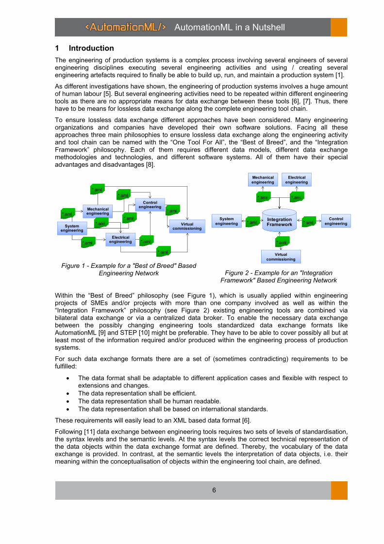
To ensure lossless data exchange different approaches have been considered. Many engineering organizations and companies have developed their own software solutions. Facing all these approaches three main philosophies to ensure lossless data exchange along the engineering activity and tool chain can be named with the “One Tool For All”, the “Best of Breed”, and the “Integration Framework” philosophy. Each of them requires different data models, different data exchange methodologies and technologies, and different software systems. All of them have their special advantages and disadvantages [8].
Figure 1 - Example for a "Best of Breed" Based Engineering Network Figure 2 - Example for an "Integration
Framework" Based Engineering Network
Within the “Best of Breed” philosophy (see Figure 1), which is usually applied within engineering projects of SMEs and/or projects with more than one company involved as well as within the “Integration Framework” philosophy (see Figure 2) existing engineering tools are combined via bilateral data exchange or via a centralized data broker. To enable the necessary data exchange between the possibly changing engineering tools standardized data exchange formats like AutomationML [9] and STEP [10] might be preferable. They have to be able to cover possibly all but at least most of the information required and/or produced within the engineering process of production systems.
For such data exchange formats there are a set of (sometimes contradicting) requirements to be fulfilled:
• The data format shall be adaptable to different application cases and flexible with respect to extensions and changes.
• The data representation shall be efficient.
• The data representation shall be human readable.
• The data representation shall be based on international standards.
These requirements will easily lead to an XML based data format [6].
Following [11] data exchange between engineering tools requires two sets of levels of standardisation, the syntax levels and the semantic levels. At the syntax levels the correct technical representation of the data objects within the data exchange format are defined. Thereby, the vocabulary of the data exchange is provided. In contrast, at the semantic levels the interpretation of data objects, i.e. their meaning within the conceptualisation of objects within the engineering tool chain, are defined.
Mechanical engineering
Electrical engineering
Control engineering
Virtual commissioning
System engineering
*.aml
*.aml
*.aml
*.aml
*.aml
*.aml
*.aml
*.aml
*.aml
Virtual
commissioning
Mechanical
engineering
Electrical
engineering
Control
engineering
System
engineeringIntegration Framework
*.aml *.aml
*.aml
*.aml
*.aml

AutomationML in a Nutshell
7
Data exchange formats can be defined in two ways, either they define syntax and semantics together as applied in the STEP approach or they define syntax and semantics separately as in the AutomationML approach. Since separate definition of semantics enables a greater flexibility and adaptability of a data exchange format to application cases this approach seems to be preferable.
In the following the Automation Mark-up Language (AutomationML) will be described in detail. It will be presented
• which engineering processes and engineering data are covered by AutomationML in the current version following the needs of the Industrie 4.0 approach (Section 2),
• what the general architecture of AutomationML is (Section 4),
• how the topology of a production system covering its hierarchy of system components and devices is represented by AutomationML (Section 5),
• how model elements of AutomationML can be enriched with semantic identifications (Section 6),
• how geometry and kinematics information are modelled by AutomationML (Section 7),
• how behaviour information are modelled by AutomationML (Section 8),
• how networks are modelled in AutomationML (Section 9),
• how additional information can related to system components and devices added to AutomationML models (Section 10), and finally
• what shall be taken into account when using AutomationML for implementing engineering chain integration within an Industrie 4.0 approach (Section 11).
2 Covered Engineering Processes and Engineering Data
The main target of application AutomationML is developed for is the field of production systems engineering and commissioning. Following the consideration of the life cycles of the different systems involved within production systems (production system, production technology, product, order) as given in [12] the relevant life cycle phases are component and technology development responsible for the design and implementation of production system components and devices, the production systems engineering executing the detailed design of a production system, and the commissioning of the production system including system testing, installation, and ramp-up (see Figure 3) which will be called plant planning process in the future.
Figure 3 - Considered Engineering Process
Focusing on the plant planning process there are different engineering processes described in literature [13], these are similar to each other just highlighting different aspects depending on the application needs [14]. Figure 4 shows an overview on this process. It consists of the five phase’s analysis, basic planning, detailed engineering, system integration, and commissioning and use.

AutomationML in a Nutshell
8
The analysis phase is dedicated to collect all requirements on the behaviour of the production system emerging from the product to be produced, the process executed for this production, and the additional requirements related to economical success, legal issues, environmental protection, etc. Therefore, the analysis phase contains the activities requirement engineering and system process planning where the requirement engineering collects the requirements and the system process engineering details the production process to be executed covering all technical functions and support functions needed to execute it. The outputs of the analysis phase are the process description of the production process to be executed as well as technical requirements to the production system.
The basic planning phase is related to the rough design of the production system without considering implementation details like using hall layout restrictions. It contains the component selection, the detailed system process planning, and the behaviour simulation. The component selection is responsible for the identification and selection of production resources to be applied within the production process to be executed. Exploiting the selected components the production process is detailed mapping the resource processes to the production process needs and adding all necessary secondary processes. Now, the detailed process on the selected resources can be simulated to initially validate especially economical requirements on the production system. The outputs of the basic planning phase are the set of selected plant components and the detailed processes executed by them.
The detailed engineering phase is related to the functional engineering of the production system finally leading to a detailed engineering of all production system parts reflecting the factory hall layout restrictions. It covers the mechanical, electrical, piping, control, robot, and HMI engineering, the process replanning, and the virtual commissioning. The mechanical engineering creates the mechanical structure of the production system required to physically execute the production processes. Therefore, all physical parts of the production system including the control devices are selected and positioned. The electrical engineering is responsible for the electrical wiring as well as the engineering of the communication system. It considers the supply of devices with energy and the layout of the signal wiring. The communication systems engineering considers the layout of the communication system and selects communication system components and technologies. Thereby, the electrical engineering finally creates signal lists. The piping engineering develops the hydraulic, pneumatic, etc. systems of the production system supplying the system components with an appropriate medium including pipes, fittings, and supply units. The control engineering implements the necessary control code required to control the behaviour of the production system. Robot programming and simulation generates code for the execution of the intended robot behaviour. Robot code allows simulating robot cells and testing the code for correctness and the processes for feasibility. HMI engineering defines variables serving as interfaces between human operators and machines, specifies and implements user interfaces and intervention possibilities in the system process. The process replanning is in parallel to all other activities within this phase. In this activity all changes are continuously collected and processed to adapt the layout and the processes of the production system. Finally, the virtual commissioning comprises all software-based analysis activities of control code executed prior to actual commissioning. The outputs of the detailed engineering phase are MCAD and ECAD drawings, device lists, wiring lists, installation guidelines, control code, etc., all necessary to set up the production system correctly.
The system integration phase is intended to install parts of the production system based on the detailed engineering of the prior phase. Therefore, the necessary parts of the production systems are acquired in the brought in parts purchase activity, all components are assembled and installed in the correspondingly named activity, the control devices are configured and programs are uploaded to controllers, robots, and HMIs, and finally the system components are tested. Thus, the outputs of the system integration phase are the set of preinstalled and tested production system components.
Finally, the commissioning and use phase is related to the final set up of the production system at its intended location and its use for product production. Within the final assembly and installation activity the preinstalled system components are moved to the final location, installed there, and tested within the complete production system. Afterwards, the system is ramped up in the commissioning activity and can be used. Parallel to the use are the monitoring and diagnosis and the maintenance activities required to ensure the future applicability of the installed production system and to repair it if necessary.

AutomationML in a Nutshell
9
Figure 4 - Plant Planning Process
Basic planning phase
Analysis phase
Requirement
engineering
System process
planning
Detailed system
process planningBehaviour simulationComponent selection
Detailed planning phase
Mechanical
engineeringElectrical engineeringProcess replanning
Control engineering HMI engineeringPiping
Supervisory control
system engineering
Virtual
commissioning
Robot programming
and simulation
System integration phase
Assembly and
installation
Device configuration /
program upload
Brought in parts
purchase
Test
Commissioning and use phase
CommissioningMonitoring /
diagnosis
Final assembly and
installation
Maintenance

AutomationML in a Nutshell
10
As visualized in Figure 4 the different engineering activities depend on each other, i.e. require engineering results of prior engineering activities. Each of them exploits different engineering tools usually optimal tailored to an efficient execution of the necessary work within one engineering activities, i.e. the optimal execution of design decisions and creation of required engineering artefacts [8]. They are based on their own model type and their own data structure optimised to the tool use and software structure. But following the chain of engineering activities it is hard to enable a consistent and lossless exchange of engineering data (digital engineering artefacts or parts of them) between the engineering tools [6].
To enable this exchange of engineering data by one data format like AutomationML this format has to be able to represent all engineering information which is relevant within at least two of the named engineering activities. Summarizing the engineering activities of the five engineering phases named above a data exchange format has to cover at least the following information sets.
• Topology data: This information set covers the hierarchical structure of the production system resources ranging from plant level over cell and function levels down to devices and mechanical parts [15], the describing attributes of the hierarchy elements, the relations between these elements, and the describing attributes of these relations.
• Mechanical data: This information set includes the mechanical construction of the production system reflected by geometry and kinematics. Usually it is given by mechanical drawings (MCAD). In addition it contains physical properties like forces, speed, and torsion or chemical properties like material information.
• Electrical, pneumatic, and hydraulic data: This information set represents the complete wiring and piping structure of the system developed by electrical construction as electrical drawings (ECAD) and piping engineering as piping plans. On the one hand it contains the connected components and their characterising properties as well as the connections between components their different types, their plugs, and their characteristics.
Figure 5 - Required Information Sets
Control RelatedInformation
Signals
PLC program organsiation
units
…
MechanicalInformation
3D CAD
Kinematics
…
Electr., Pneum.,Hydrau. Information
Wiring
Connections
Piping
...
TopologicalInformation
Plant- and device structure
Layout
Interfaces
Economical Informationen
Vendor information
Part number
Price
…
Further Technical Information
Weight
Energy consumption
Technical documentation
Function DescribingInformation
Function description
Functional parameters
Technological parameters
….

AutomationML in a Nutshell
11
• Function describing data: This information set covers information relevant to characterise the function of a production system component. Thus, it contains functional models of controlled and uncontrolled behaviour, functional parameters, technological parameters, etc. all relevant to appropriately describe the production process as well as other processes executable by the component.
• Process control data: This information set contains all control device related information like hardware configuration, control code, control parameters, etc.
• Generic data: This information set summarizes further organizational, technical, economical, and other information like order data, handbooks, and guidelines.
These information sets are depicted in
Figure 5. AutomationML is able to represent of all these information sets as presented in the next section.
3 Running Example
In the following, the modelling of the identified information is presented. To accompany abstract presentation of modelling rules, a running example is used for a better understanding. This running example is part of a lab size production system hosted at IAF of the Otto-v.-Guericke University Magdeburg. It consists of a set of multipurpose machines, turntables, and conveyers and is wired using Field IOs to Raspberry Pi based controllers as depicted in Figure 6.
From this lab size production system only a very small but representative part is used (see Figure 7). It comprises one turntable containing at least two devices, an inductive sensor for material detection, and a drive for table rotation. Both devices have at least one pin to connect them to a modular Field-IO by a wire. This Field-IO is established by a Modbus TCP Ethernet fieldbus coupler used by the controller to access physical inputs and outputs. The Field-IO is again connected to a Raspberry Pi based controller via an Ethernet cable. The Raspberry Pi based controller is running a PLC program controlling the turntable.
PI based
controller1Wago IO
Turntable 1

AutomationML in a Nutshell
12
Figure 6 - Lab Size Production System as Running Example
Figure 7 - Considered Part of the Running Example
4 General Architecture of AutomationML
The AutomationML data format has been developed by AutomationML e.V. (see [16]) as solution for the data exchange focusing on automation system engineering but able to cover all information relevant within the engineering of production systems. It is an open, vendor neutral, XML-based, and free data exchange format which enables a domain and company spanning transfer of engineering data of production systems in a heterogeneous engineering tool landscape.
AutomationML stores engineering information following the object oriented paradigm and allows the modelling of physical and logical plant components as data objects encapsulating different aspects. Objects may constitute a hierarchy, i.e. an object may consist of sub-objects and may itself be a part of a larger composition or aggregation. Additionally each object can contain information about object describing properties covering geometry, kinematics, and logic (sequencing, behaviour, and control information) as well as further properties.
AutomationML follows a modular structure by integrating and enhancing/adapting different already existing XML-based data formats combined under one roof the so called top level format (see Figure 8).
These data formats are used on an “as-is” basis within their own specifications and are not branched for AutomationML needs. Logically AutomationML is partitioned in:
• Description of the component topology and networking information including object properties expressed as a hierarchy of AutomationML objects and described by means of CAEX following IEC 62424 [17],
Turntable 1
PI based
Controller 1 Program
Network
card
Wago I/O A
Variable declaration: Boolean MotorAn, SensorWert;
Koppler
750-341DI1
750-437
DI2
750-437
DO1
750-530
DO2
750-530
IO
Register
Input
Register
Bit 1
Drive
Pin A
Sensor
Pin 1
IOcabel_Drive_DO1
IOCabel_Sensor_DI1
Output
Register
Bit 1
EthernetCabel1
ReadinputRegister
WriteOutputRegister

AutomationML in a Nutshell
13
• Description of geometry and kinematics of the different AutomationML objects represented by means of COLLADA 1.4.1 and 1.5.0 (ISO/PAS 17506:2012) [18],
• Description of control related logic data of the different AutomationML objects represented by means of PLCopen XML 2.0 and 2.0.1 [19], and
• Description of relations among AutomationML objects and references to information that is stored in documents outside of the top level format using CAEX means.
Figure 8 - Structure of AutomationML Projects
AutomationML is currently standardized within the IEC standard series IEC 62714 [20]. For a more detailed description of AutomationML see [9] and [16].
The foundation of AutomationML is the application of CAEX as top level format and the definition of an appropriate utilization fulfilling all relevant needs of AutomationML to model engineering information of production systems, to integrate the three named data formats CAEX, COLLADA, and PLCopen XML, and to enable an extension if necessary in the future.
CAEX enables an object oriented approach (see Figure 9) where semantics of system objects can be specified using roles defined and collected in role class libraries. Interfaces between system objects can be specified using interfaces classes defined and collected in interface class libraries. Classes of system objects can be specified using system unit classes (SUC) defined and collected in system unit class libraries. Finally, the individual project objects are modelled in an instance hierarchy (IH) as a hierarchy of internal elements (IE) referencing both system unit classes they are derived from and role classes defining their semantics and interface objects used to interlink objects among each other or with externally stored information (e.g. COLLADA or PLCopen XML files). For details on this structure the authors refer to the different AutomationML whitepapers available at [16].
Additional and essential features of AutomationML are the separation of syntax and semantics of data objects based on the libraries of role classes and system unit classes and referencing to library elements out of the instance hierarchy, the provision of identification capabilities for objects based on UUIDs, the provision of version information including version identification and version history information based on appropriate object attributes, the provision of data source identification information based on appropriate object attributes, and the provision of data structuring capabilities beyond object hierarchies exploiting the facet and group concept.
1
Top level format
CAEX IEC 62424
Plant Topology Information
Mechatronics
Networks
Devices
Attributes
Geometry
andKinematic format
COLLADA
Logic
formatPLCopenXML
Semantic
referencing
Further aspects
in other XMLformat
D1 D2
Dn
IEC 62714Plant Planning
Functional engineering
Commissioning

AutomationML in a Nutshell
14
Figure 9 - AutomationML Topology Description Architecture
5 System Topology and System Element Modelling
As named in the last section AutomationML exploits CAEX for modelling the system topology and the system elements. Therefore, AutomationML provides four main modelling means.
The first means comprises role classes collected within role class libraries. A role class describes an abstract functionality without defining the underlying technical implementation, thus, it has to be seen as an indicator for the semantics of an object. This can be for example the role classes MechanicalPart and Device indicating system structure semantics or LogisticalDevice and PhysicalDevice representing communication system semantics. AutomationML defines a set of basic role classes represented in Figure 10. There are the AutomationMLBaseRoleClassLib with fundamental role classes defined in Part 1 of the AutomationML standard [20] and the CommunicationRoleClassLib defined in the Part 5 [16].

AutomationML in a Nutshell
15
Figure 10 - AutomationML BaseRoleClass Library and CommunicationRoleClass Library
Further role classes are defined in Part 2 of the AutomationML standard [16]. Each AutomationML user can define new role classes following its use cases and needs for data exchange. AutomationML only defines some rules for role class definition.
Each role class shall have a unique name within the role tree of a role class library. Thereby, it can be uniquely referenced by this hierarchy path. The Port role depicted in Figure 11 has the identification path AutomationMLBaseRoleClassLib/AutomationMLBaseRole/Port. In addition, each role class has to be derived directly or indirectly from AutomationMLBaseRole by using the RefBaseClassPath attribute.
Each role class may have attributes and interfaces. These attributes and interfaces shall enable an importer of an engineering tool to interpret and process incoming information correctly.

AutomationML in a Nutshell
16
Figure 11 - Port Role Class as Example of Role Definition
An example of a user defined role class can be a ModbusTCPPhysicalDevice role class with the attributes MACaddress and IPAddress as defined in the running example representing a control device able to communicate over Modbus TCP.
The second modelling means are the interface classes. An interface class describes an abstract relation an element can have to other elements or to information not covered within the CAEX based model (see geometry and kinematics modelling and behaviour modelling). This can be for example the interfaces SignalInterface and PhysicalEndPoint indicating provided interfaces for signal processing of cable plugging or ExternalDataConnector representing the association to externally stored information. AutomationML defines a set of basic interfaces represented in Figure 12. There are the AutomationMLInterfaceClassLib with fundamental interfaces defined in Part 1 [20] of the AutomationML standard and the CommunicationInterfaceClassLib defined in the upcoming Part 5 [16].
Each AutomationML user can define new interface classes following its use cases and needs for data exchange. AutomationML only defines some rules for interface class definition:
Each interface class shall have a unique name within the interface class tree of an interface class library. Thereby, it can be uniquely referenced by this hierarchy path. The COLLADAInterface interface class depicted in Figure 13 has the identification path AutomationMLInterfaceClassLib/AutomationMLBaseInterface/ExternalDataConnector/COLLADA.........Interface. In addition, each interface class has to be derived directly or indirectly from AutomationMLBaseInterface by using the RefBaseClassPath attribute.
Each interface class may have attributes. These attributes have to be used and filled with values in each occurrence of an instance of the interface class.
An example of a user defined interface class can be a ModbusTCPSocket interface class as defined in the running example representing the plugging position for an Ethernet cable within a control device able to communicate over Modbus TCP.

AutomationML in a Nutshell
17
Figure 12 - AutomationML InterfaceClass Library and CommunicationInterfaceClass Library
Figure 13 - COLLADAInterface Class as Example for Interface Definition
The third modelling means are system unit classes. System unit classes can be considered as reusable system components or as templates for system modelling depending on the point of view. Usually they reflect either a vendor dependent library of components or devices or a set of templates used within an engineering tool to structure discipline dependent model information.

AutomationML in a Nutshell
18
Within the AutomationML standard there is no basic AutomationML system unit class library defined. Thus, the definition of system unit class libraries is up to the user of AutomationML. AutomationML only defines some rules for system unit class definition.
Each system unit class shall have a unique name similar to role classes and interface classes. It shall have at least one role class assigned to it giving the system unit class a semantic by using the SupportedRoleClass sub-element.
Each system unit class may have sub-objects of the type InternalElement, attributes, and interfaces representing the structure of the modelled class of objects, its properties, and its possible associations. In addition, each system unit class may be derived from another system unit class by using the RefBaseClassPath attribute. In this case it inherits all supported role classes, sub-elements, interfaces, and attributes from the parent element.
An example of a user defined system unit class library is given in Figure 14 and an example of a user defined system unit class Motor representing a drive class is given in Figure 15.
Figure 14 - Example System Unit Class Library
Figure 15 - Motor System Unit Class as Example for System Unit Class Definition

AutomationML in a Nutshell
19
All modelling concepts may have attributes. Attributes are seen as properties which can be assigned to role classes, interface classes, system unit classes, and internal elements.
AutomationML defines some rules for attribute definition. Each attribute shall have a unique name within its parent element. It may have a DataType and a Unit attribute and sub-elements for description, default value, value, and semantic referencing. An example of a user defined attribute is given in Figure 16.
Figure 16 - Herstellerartikelnummer Attribute as Example for Attribute Definition
The most important modelling means is the InstanceHierarchy with its integrated hierarchy of InternalElements. It represents the actual engineering data to be modelled by CAEX following an object oriented and hierarchical structure.
The workhorse of the representation of actual engineering data is the InternalElement. It is the representative of an object in the production system to be modelled. Depending on the level of abstraction it can represent physical components like the complete plant, functional component as machines and turntables, a device as a drive or a controller, or just a mechanical part as a conveyer belt or a wire. Also, it can represent logical components like a PLC program, a product description, or an order.
Figure 17 - Simplified Structure of an InstanceHierarchy
InstanceHierarchy
IH
InternalElement
IE
1
1..*
1
0..*
Attribute
Role class
RC
System unit class
SUC
RoleRequirement
SupportedRoleClass
1
10..*
0..1
1 Interface10..*
0..*
1
1
Re
fBa
seSy
ste
mU
nit
Pa
th

AutomationML in a Nutshell
20
InternalElements in the InstanceHierarchy are generally user defined. They can contain attributes and interface instances derived from interface classes of any interface class library. They can reference a system unit class from an arbitrary system unit class library by using the RefBaseSystemUnitPath attribute. This reference will identify the corresponding system unit class as the parent class the InternalElement is derived from and, thereby, name the system unit class as template for the InternalElement. This will lead to the fact that the InternalElement shall have the same substructure, interfaces, and attributes as defined in the system unit class. In addition, the InternalElement shall reference at least one (but possible more than one) role class from an arbitrary role class library. Therefore, the RoleRequirements and the SupportedRoleClass sub-objects shall be applied. The referenced role class will define the semantics of the InternalElement. The structure an InternalElement is depicted in Figure 17.
An example InstanceHierarchy modelling the running example is given in Figure 19. Here the hierarchy of physical and logical entities can be found ranging from the highest InternalElement FlexibleManufacturingSystem over InternalElements representing the turntable (Drehtisch1), the IO fieldbus coupler (WagoIOA) and the controller (PIBasedControllerA) down to InternalElements representing the control application (MyPIProgram), control devices (myMotor) or wires (IOKabel_Motor_DO1_DrathB).
An example of an InternalElement is given in Figure 18. It depicts the wire connecting the drive with the field IO. This InternalElement has several attributes like Polzahl representing the number of leads in the wire and min. zulässige Kabeaußentemperatur representing the minimal acceptable temperature of the wire surface. In addition it has two interfaces representing both end points of the wire.
Figure 18 - IOKabel_Motor_DO1_DrathB as Example for an InternalElement

AutomationML in a Nutshell
21
Figure 19 - InstanceHierarchy of the Example (Extract)
6 Integration of Object Semantics
A critical point during the import of data within engineering tools is the mapping of the incoming data to the data model of the importing tool. Therefore, it has to be decided for each datum, which semantics the datum has related to the importing tool.

AutomationML in a Nutshell
22
Within the import process of AutomationML based data the exchanged data are given within the InstanceHierarchy either as InternalElements or as attributes.
To identify the semantics of InternalElements AutomationML provides two main mechanisms: referencing of role classes and referencing of system unit classes. For referencing of role classes with the sub-objects RoleRequirements and SupportedRoleClass two means are provided. They can contain the complete role class name including the role class path. For the representation of semantics of an attribute the RefSemantic sub-attribute of an attribute can be exploited. It is given for each AutomationML attribute. Figure 20 recapitulates all these means for semantics representation.
Figure 20 - Means for Semantic Integration in InternalElements and Attributes
AutomationML will not define semantics of production system components itself. Instead it integrates existing semantic definitions as given for example in the eCl@ss classification standard [21].
eCl@ss is a hierarchical semantic system for grouping materials, products and services according to a logical structure with a level of detail that corresponds to the product-specific properties that can be described using standard conform properties. eCl@ss classifies materials, products, and services enabling a unique identification of production system component classes like devices types or installation material types. For each class standardized properties are defined useable to specify the individual characteristics of the class instances.
Key element of the eCl@ss specification is the IRDI (International Registration Data Identifier) which is based on the international standards ISO/IEC 11179-6, ISO 29002, and ISO 6532. The IRDI provides a unique identification code for each attribute and each class of objects.
To reference the semantics of an attribute AutomationML will exploit the referencing of the IRDI of eCl@ss properties. Therefore, the attribute CorrespondingAttributePath of the CAEX schema element RefSemantic shall be assembled as the string “ECLASS: ” + IRDI of the eCl@ss property defining the semantics of the AutomationML attribute.
Figure 21 depicts an example for the use of RefSemantic to specify the semantics of an AutomationML attribute. Here, the attribute max. Versorgungsspannung representing the maximal applicable supply voltage for an inductive sensor is given. This attribute is semantically defined by the IRDI 0173-1#02-AAC962#006.
The semantic representation of InternalElements is more complicated. It applies the role class concept. The classification of the classification standard of interest (in this case eCl@ss) is modelled as an AutomationML user defined role class library. Thereby, on the one hand the hierarchical structure of the classification shall be preserved and on the other hand each derived role classes shall have three attributes applicable to identify the class. These attributes will contain information on the version of the classification standard, the identification of the class, and the class IRDI. An example of such a role class library for the running example is given in Figure 22.
Attributes
InternalElement
RefBaseSystemUnit
Path
SupportedRoleClass
RoleRequirements
………
………
…
Attribute
RefSemantic
………

AutomationML in a Nutshell
23
Figure 21 - Example of Semantic Representation for Attributes
Figure 22 - Example Role Class Library for Semantics Representation
The developed role classes are then referenced by InternalElements using the RoleRequirements and the SupportedRoleClass sub-objects. An example for a drive of the running example is given in Figure 23. It presents the indication of the InternalElement myMotor as an IEC DC drive with the class identification 27-02-25-01.

AutomationML in a Nutshell
24
Figure 23 - Example for Semantics Representation for InternalElements
7 Geometry and Kinematics
As named above AutomationML exploits the international standard COLLADA 1.4.1 and 1.5.0 for the representation of geometry and kinematics information which is standardized as ISO/PAS 17506:2012 [18]. Therefore, AutomationML has developed a two stage process. At first, relevant geometries and kinematics are modelled as COLLADA files. At second, these files and the data objects within them are referenced out of the CAEX file.
COLLADA stands for COLLAborative Design Activity. It has been developed by the KHRONOS association under the leadership of Sony as an intermediate format within the scope of digital content creation in the gaming industry. It is designed to enable the representation of 3D objects within 3D scenes covering all relevant visual, kinematic, and dynamic properties needed for object animation.
COLLADA [26] is an XML-based data format with a modular structure enabling the definition of libraries of visual and kinematic elements. It can contain libraries for representation of geometries, materials, lights, cameras, visual scenes, kinematic models, kinematic scenes, and others. An example of a COLLADA file is given in Figure 24. The left upper picture represents an original conveyer of the running example while the left lower picture is the corresponding model. The right picture represents the COLLADA file of this model.
The most important feature enabling the integration of COLLADA files in AutomationML projects is the availability of an unique identification of objects within a COLLADA file. Several data objects within a COLLADA file have a unique identification (ID) like geometries, visual scenes, kinematic models and kinematic scenes.
For referencing those objects AutomationML has defined a special interface class within the AutomationMLInterfaceClassLib named COLLADAInterface which shall be applied to derive the needed interfaces for geometry integration. This interface class (as presented in Figure 25) itself is derived from the interface class ExternalDataConnector and has, thereby, an attribute refURI. This attribute can be applied to reference into a COLLADA file pointing to an ID of an object modelled in the COLLADA file. Therefore, the value of the refURI attribute shall contain a string structured like file:///filename.dae#ID. The attribute refType is applied to define the way an object is embedded within a scene of a model enabling the modelling of attachments of objects like a work piece which is attached to a conveyer belt and is moved when the belt is moving.

AutomationML in a Nutshell
25
Figure 24 - Example COLLADA File (Extract)
Figure 25 - Definition of COLLADAInterface Interface Class
An example of the integration of a geometry in an AutomationML project is depicted in Figure 26. It shows how a system unit class Motor can be enriched by its geometry representation.
Naturally, an InstanceHierarchy may contain more than one InternalElement with a geometry assigned to. To enable the proper positioning of these geometries within the overall set of geometries each InternalElement may have an attribute usable to specify the position of the assigned geometry related to the coordinate system of the parent InternalElement. This frame attribute depicted in Figure 27 enables the specification of the offset of the geometry in the Cartesian directions x, y, z as well as its rotation around these axes.

AutomationML in a Nutshell
26
Figure 26 - Example of Geometry Integration
Figure 27 - Example of a Frame Attribute

AutomationML in a Nutshell
27
8 Behaviour Modelling
Similar to the modelling of geometry and kinematics AutomationML exploits for behaviour representation an additional XML-based data format named PLCopen XML [19] developed by the PLCopen association. AutomationML has developed a two stage process for behaviour modelling and integration as well. At first, relevant behaviour is modelled as PLCopen XML files. At second, these files and the data objects within them are referenced from the CAEX file.
PLCopen is a vendor and product independent worldwide association aiming at resolving topics related to control programming to support the use of international standards in this field. It especially promotes the use of IEC 61131-3 standard for industrial control programming. With PLCopen XML the PLCopen has developed a data format applicable as an open interface between all different kinds of software environments providing the ability to transfer PLC programming project information to other platforms. AutomationML exploits version 2.01 of the PLCopen XML schema published in May 2009. This version covers most of the IEC 61131-3 2nd edition.
A PLCopen XML file is structured in a way representing all essential parts of an IEC 61131 PLC programming project. It covers tool information, the developed program code preserving the program structure, and PLC hardware information. Most relevant for AutomationML is the representation of Program Organisation Units (POUs) as represented in Figure 28. Each POU describes one structural unit of an PLC program containing the source code of the program in one of the five IEC 61131 programming languages and the variable declaration for this program. Each of these parts may have a global identifier applicable to uniquely reference the element.
Figure 28 - Example PLCopen XML File
As AutomationML intends to cover the complete engineering process of a production system different levels of behaviour modelling have to be considered. As presented in Figure 29 they range from abstract process planning modelled as sequences with Gantt or PERT Charts over sequencing and interlocking of field device signals modelled by Impulse Diagrams and Logic Networks down to

AutomationML in a Nutshell
28
detailed code representation as PLCopen programs or detailed component behaviour modelling based on the automaton approach following Harels State Charts [22].
AutomationML has decided not to apply all of the IEC 61131 programming languages for behaviour representation. As most of the relevant model types represent discrete event dynamic systems it was decided to represent sequencing models by Sequential Function Charts (SFC). Thus, AutomationML has defined transformation rules mapping the modelling means of the named model types to SFC model elements. For details see [9], [16], and [22]. For the representation of Logic Networks Function Block Diagrams (FBD) shall be applied. Both, SFC and FBD models can be expressed by PLCopen XML.
Figure 29 - Model Types Reflected by AutomationML Logic Description
For referencing PLCopen file content AutomationML has defined a special interface class within the AutomationMLInterfaceClassLib named PLCopenXMLInterface which shall be applied to derive the needed interfaces for behaviour integration. This interface class (as presented in Figure 30) is also derived from the interface class ExternalDataConnector and has, thereby, an attribute refURI. This attribute can be applied to reference into a PLCopen XML file pointing to a globalID of either a complete POU or a variable applied within this POU. Therefore, the value of the refURI attribute shall contain a string structured like file:///filename.xml#globalID.
Figure 30 - Definition of PLCopenXMLInterface Interface Class
Planning
Control System Behavior
Interlocking
Control System Implementation
Component Behavior
Product
Design
Plant
Planning
Mech.
Constr.
Electr.
Constr.
PLC
Progr.
Robot
Progr.
HMI
Progr.
Virtual
Comm.
Gantt Chart
Pert Chart
Impulse diagram
Logical Networks
SFC
State Charts
SFC

AutomationML in a Nutshell
29
An example of the integration of a behaviour model in an AutomationML project is depicted in Figure 31. It shows how a system unit class Motor can be enriched by its behaviour representation.
Figure 31 - Example of Behaviour Integration
9 Modelling of Networks
Production systems can contain several types of networks like wiring and piping networks, communication networks, or transportation networks. All of these networks have in common that they can be represented by a graph based structure. Thus, AutomationML has developed a methodology for modelling graph based structures and has applied this methodology to different types of networks [24].
A graph G = (V (G), E (G)) is defined by two non empty sets: vertex set V (G) and edge set E (G).
These sets have the property that E (G) ⊆ V (G) x V (G) holds, i.e. the vertices are linked by the edges [25]. If information is added to the objects of a graph it can be seen as labels of the related objects. Labels can have different forms, for example real numbers or even text boxes. For the development of graph models labels are one of the most important characteristics. For labelled graphs the definition above has to be extended. A labelled graph LG = (V (G), E (G), L1, L2) is a graph with two additional mappings L1, L2. For the mappings holds that there are annotation sets A1 and A2 with L1: V(G) A1 is a mapping of the vertex set into the annotation set 1 and L2: E(G) A2 is a mapping of the edge set into the annotation set 2.
Starting point for modelling graphs is the definition of transformation rules to map the graph objects vertex and edge to AutomationML objects by means of CAEX. Thus, an InternalElement is generated as representative of the entire graph. Characteristics and additional information describing the graph, i.e. labels, can be attached to this element by means of attributes. Then the elements of the vertex set and edge set are created as child objects of the parent object graph. First of all, all vertices of the graph and their associated labels are transformed into the form of an InternalElement and its attributes. Afterwards, edges are transformed in a similar way. For greater clarity it is suggested that the edge objects are created as child objects of an additional InternalElement for the edge set. To express relations between vertices and edges interfaces are used. Therefore, all InternalElements

AutomationML in a Nutshell
30
representing vertices have as much interfaces as they have incident edges and all InternalElements representing edges usually have two interfaces. Interfaces of incident edges and vertices can then be linked by internal links. An example is given in Figure 32.
Figure 32 - Example of a Graph Model in AutomationML
At first, AutomationML has applied this methodology to model communication networks. Therefore, all relevant objects to be modelled in a graph based structure have been identified, relevant role and interface classes have been defined, and a modelling methodology has been proposed (see Part 5 [16]).
Each communication network is considered on two layers: a logical layer and a physical layer. The logical layer consists of control application building blocks providing different functionalities of the control process and forming logical devices. In general, these logical devices (control application parts) have to exchange information of different types which can be seen as connection points to the logical devices and end points of the information exchange between logical devices. The information exchange itself is executed by different logical connections. The logical network can contain different objects with different describing properties. While logical devices can have unique identifiers, cycle times, and storage foot print (to name only a few examples), logical end points can have a data type, and logical connections may have a required transmission rate. In any case these describing properties can be considered as attributes of the objects of interest.
Looking at the physical layer physical devices can be found. They have physical endpoints representing network interfaces like plugs and sockets and are connected via physical connections to a communication system. Compared to the logical layer view there are additional physical entities representing infrastructure components of the network (like switches etc.). Similar to the logical network the physical network objects can have different describing properties. While physical devices can have processor capacity or identifiers, physical end points may have an address or a maximal data rate, and physical connections can have a possible transmission rate, a wire type, or a documentation number. In any case these de-scribing properties can be considered as attributes of the objects of interest again.
Both layers need to be combined to get the complete network description. Therefore, logical devices are hosted by physical devices. In addition, physical interfaces and logical interfaces are mapped. Thereby, each logical connection is mapped virtually to a set of physical connections implementing it. It is not strictly necessary that there is a unique chain of physical connections representing this implementation like it is not given in some communication technologies. The resulting structure is represented in Figure 33.

AutomationML in a Nutshell
31
Figure 33 - Communication System Structure Represented by AutomationML
Within communication systems communication datagrams (known as Protocol Data Units / PDU) are exchanged between control application parts. Hence, they belong to a logical connection. Each PDU contains control information (sensor and actuator signals, status, alarms, etc.) modelled in AutomationML based on interfaces of PLCopenXMLInterface type (see above). Thus, each logical connection has to contain PDU objects exchanged via this connection. Each of the PDU objects is linked to a PLCopenXMLInterface or a SignalInterface modelling the exchanged information.
Basis of the method for communication system modelling within AutomationML is the definition of an AutomationML role class library and an AutomationML interface class library and the derivation of relevant role classes and interface classes for the special application cases from them. The AutomationML communication role class library will contain roles dedicated to identify InternalElements as physical devices, physical connections, and physical networks as well as InternalElements as logical devices, logical connections, logical networks, and communication packages. The AutomationML interface class library contains interface classes for physical end points, logical end points, and communication datagram objects. Both libraries are depicted in the upper part of Figure 34 named CommunicationRoleClassLib and CommunicationInterfaceClassLib.
Exploiting these basic role and interface classes special classes can be derived identifying devices and connections related to special applications and communication technologies. Thereby, role class libraries and interface class libraries for special purposes have to be developed. An example is given in the lower part of Figure 34 named ModbusTCPRoleClassLib and ModbusTCPInterfaceClassLib.
PLC IO Device
Physical
device
Active infra-
structure device
Main control
applicationIO function
Physical
end point
of device
Logical device
Logical
end point
of device
Physical
connection
with end
point
Logical
connection
with end
points
Mapping of
logical to
physical
interfaces
Wire 1
Wire 2
Logical Connection A
AutomationML
Communication
Variable /
Signal
interface
Mapping of
Variable /
Signal
interface to
datagram
object
Datagram
object
PDU
PDU 1
AutomationML in a Nutshell
32
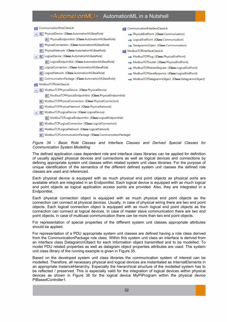
Figure 34 - Basic Role Classes and Interface Classes and Derived Special Classes for Communication System Modelling
The defined application case dependent role and interface class libraries can be applied for definition of usually applied physical devices and connections as well as logical devices and connections by defining appropriate system unit classes within related system unit class libraries. For the purpose of unique identification of the semantics of the different defined system unit classes the defined role classes are used and referenced.
Each physical device is equipped with as much physical end point objects as physical ports are available which are integrated in an Endpointlist. Each logical device is equipped with as much logical end point objects as logical application access points are provided. Also, they are integrated in a Endpointlist.
Each physical connection object is equipped with as much physical end point objects as the connection can connect at physical devices. Usually, in case of physical wiring there are two end point objects. Each logical connection object is equipped with as much logical end point objects as the connection can connect at logical devices. In case of master slave communication there are two end point objects, in case of multicast communication there can be more than two end point objects.
For representation of special properties of the different system unit classes appropriate attributes should be applied.
For representation of a PDU appropriate system unit classes are defined having a role class derived from the CommunicationPackage role class. Within this system unit class an interface is derived from an interface class DatagrammObject for each information object transmitted and to be modelled. To model PDU related properties as well as datagram object properties attributes are used. The system unit class library of the running example is given in Figure 35.
Based on the developed system unit class libraries the communication system of interest can be modelled. Therefore, all necessary physical and logical devices are instantiated as InternalElements in an appropriate InstanceHierarchy. Especially the hierarchical structure of the modelled system has to be reflected / preserved. This is especially valid for the integration of logical devices within physical devices as shown in Figure 36 for the logical device MyPIProgram within the physical device PIBasedController1.

AutomationML in a Nutshell
33
Figure 35 - System Unit Class Library for the Running Example
After defining all devices the relevant attributes of the devices have to be completed and filled with values.
If the devices have been completed they can be connected by connections. Therefore, in the InstanceHierarchy of the network two InternalElements are instantiated implementing role classes derived from the role classes PhysicalNetwork and LogicalNetwork. They are containers for all physical and logical connection objects. For each physical connection one InternalElement with a role class derived from the role class PhysicalConnection is instantiated. It is completed by appropriate attributes and their values. For each logical connection one InternalElement with a role class derived from the role class LogicalConnection is instantiated. Also, this InternalElement is completed by appropriate attributes and their values.
If all necessary devices and connections are instantiated they are connected by exploiting InternalLinks. Therefore, for each logical device and each logical connection, which are interconnected, the related logical end points are interrelated by an internal link object. Also for each physical device and each physical connection, which are interconnected, the related physical end

AutomationML in a Nutshell
34
points are interrelated by an internal link object. To map also the logical end points to physical end points implementing the related connections internal link objects are used. For the running example the resulting structure is depicted in Figure 37.
Figure 36 - Example of the Communication System Hierarchy of the Running Example
AutomationML in a Nutshell
35
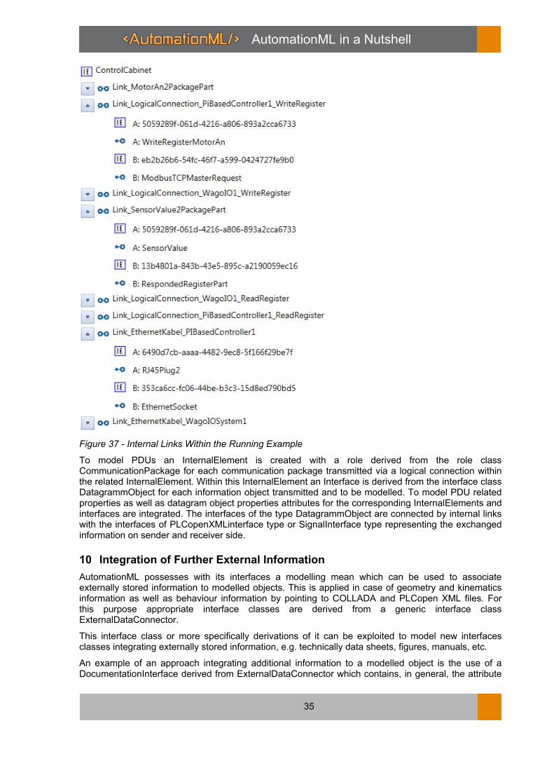
Figure 37 - Internal Links Within the Running Example
To model PDUs an InternalElement is created with a role derived from the role class CommunicationPackage for each communication package transmitted via a logical connection within the related InternalElement. Within this InternalElement an Interface is derived from the interface class DatagrammObject for each information object transmitted and to be modelled. To model PDU related properties as well as datagram object properties attributes for the corresponding InternalElements and interfaces are integrated. The interfaces of the type DatagrammObject are connected by internal links with the interfaces of PLCopenXMLinterface type or SignalInterface type representing the exchanged information on sender and receiver side.
10 Integration of Further External Information
AutomationML possesses with its interfaces a modelling mean which can be used to associate externally stored information to modelled objects. This is applied in case of geometry and kinematics information as well as behaviour information by pointing to COLLADA and PLCopen XML files. For this purpose appropriate interface classes are derived from a generic interface class ExternalDataConnector.
This interface class or more specifically derivations of it can be exploited to model new interfaces classes integrating externally stored information, e.g. technically data sheets, figures, manuals, etc.
An example of an approach integrating additional information to a modelled object is the use of a DocumentationInterface derived from ExternalDataConnector which contains, in general, the attribute

AutomationML in a Nutshell
36
refURI pointing to the external document and an attribute MIMEType specifying the document type according to the MIME standard (Multipurpose Internet Mail Extensions). Depending on the number of documents which has to be assigned to an object InternalElements are created as child elements. Additionally, a role class library is modelled defining specific semantics, e.g. role classes for specifications, technical data sheets, figures, manuals, etc. One or more of these role classes are assigned to the corresponding InternalElement.
By this means, additional information sets can be modelled as InternalElements with role defined semantics and a DocumentationInterface which references to a document as well as identification of the document type.
These technologies can be applied to several data formats of interest [23]. An example for the integration of manuals as part of the additional data facets available in PDF format is given in Figure 38.
Currently the AutomationML association is working on the detailed specification of mechanisms to associate externally stored information to modelled objects.
Figure 38 - Example of Integration of a pdf Document in AutomationML
11 Application Process
The AutomationML specification only defines the representation of information based on the application of CAEX, COLLADA, and PLCopen XML. Nevertheless, the use of AutomationML enforces an application process, which is more or less implicitly defined. This process is based on a general view on data exchange and consists of two main phases covering at first the identification of the data set to be exchanged and at second the modelling of the identified data set.
New
New
New
AutomationML in a Nutshell
37
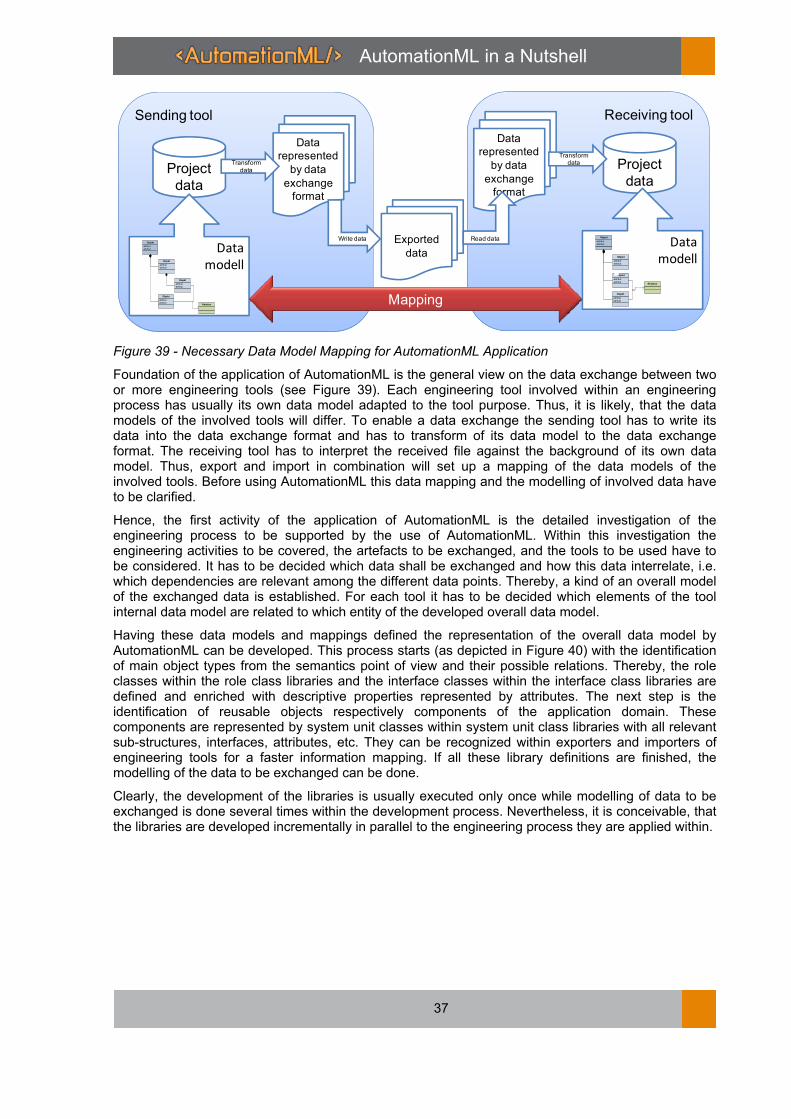
Figure 39 - Necessary Data Model Mapping for AutomationML Application
Foundation of the application of AutomationML is the general view on the data exchange between two or more engineering tools (see Figure 39). Each engineering tool involved within an engineering process has usually its own data model adapted to the tool purpose. Thus, it is likely, that the data models of the involved tools will differ. To enable a data exchange the sending tool has to write its data into the data exchange format and has to transform of its data model to the data exchange format. The receiving tool has to interpret the received file against the background of its own data model. Thus, export and import in combination will set up a mapping of the data models of the involved tools. Before using AutomationML this data mapping and the modelling of involved data have to be clarified.
Hence, the first activity of the application of AutomationML is the detailed investigation of the engineering process to be supported by the use of AutomationML. Within this investigation the engineering activities to be covered, the artefacts to be exchanged, and the tools to be used have to be considered. It has to be decided which data shall be exchanged and how this data interrelate, i.e. which dependencies are relevant among the different data points. Thereby, a kind of an overall model of the exchanged data is established. For each tool it has to be decided which elements of the tool internal data model are related to which entity of the developed overall data model.
Having these data models and mappings defined the representation of the overall data model by AutomationML can be developed. This process starts (as depicted in Figure 40) with the identification of main object types from the semantics point of view and their possible relations. Thereby, the role classes within the role class libraries and the interface classes within the interface class libraries are defined and enriched with descriptive properties represented by attributes. The next step is the identification of reusable objects respectively components of the application domain. These components are represented by system unit classes within system unit class libraries with all relevant sub-structures, interfaces, attributes, etc. They can be recognized within exporters and importers of engineering tools for a faster information mapping. If all these library definitions are finished, the modelling of the data to be exchanged can be done.
Clearly, the development of the libraries is usually executed only once while modelling of data to be exchanged is done several times within the development process. Nevertheless, it is conceivable, that the libraries are developed incrementally in parallel to the engineering process they are applied within.
Sending tool
Project
data
Data
modell
-attribut
-attribut
Objekt
-attribut
-attribut
Objekt1
-attribut
-attribut
Objekt
1
-attribut
-attribut
Objekt
1
Relation
Receiving tool
Project
data
Data
modell
-attribut
-attribut
Objekt
-attribut
-attribut
Objekt1
-attribut
-attribut
Objekt
1
-attribut
-attribut
Objekt
1
Relation
Exported
data
Mapping
Data
represented
by data
exchange
format
Data
represented
by data
exchange
format
Transform
data
Write data Read data
Transform data

AutomationML in a Nutshell
38
Figure 40 - Phases of Implicit AutomationML Application Process
12 Conclusions
Within this paper the current state of development of the data exchange format AutomationML has been presented. Within the last 10 years from the initiation of the development of AutomationML by nine companies and research entities a widely applicable data exchange format has been developed able to cover the needs of production systems engineering. It is able to represent the engineering results of the production system structure definition, the mechanical, electrical, piping, control, etc. engineering, the virtual commissioning, and, finally, the installation and commissioning. Thus, it is applicable to engineering tool integration in heterogeneous tool landscapes as required in Industrie 4.0 approaches.
Today with more than 30 members the AutomationML association expedites the standardisation process of AutomationML and develops application guidelines for several specialised application cases. On the one hand, these cases cover the exchange of special engineering information. On the other hand, structures and procedures of engineering embedding engineering data exchange scenarios are investigated. Related to special engineering information, for example, the modelling of the configuration of automation device networks, the modelling of production processes and the utilization of resources within them to create products, and the definition of specialised role libraries for transportation system elements are considered. Related to data exchange scenarios the current focus is on the use of OPC UA to exchange AutomationML modelled data, the integration of AutomationML modelled data in data management systems, and the identification of requirements emerging from different types of engineering network structures following water fall or spiral like engineering processes.
The further development of AutomationML towards an optimal adjustment of the data format and its usability towards a complete fulfilment of the requirements of engineering chain integration in Industrie 4.0 is the main aim of the AutomationML members. Each company and each research entity interested in joining this process is welcome.
Development of
interface
classes for the
application case
Development of
system unit
classes for the
application case
Development of
role classes for
the application
caseDevelopment of
system unit
class details
System
modeling
for data
exchange
AutomationML in a Nutshell
39
Literature
[1] W. Terkaj, T. Tolio und A. Valente: Focused Flexibility in Production Systems, in Changeable and Reconfigurable Manufacturing Systems, Springer Series in Advanced Manufacturing, 2009, I, 47-66.
[2] H. Kagermann, W. Wahlster, J. Helbig (Editoren): Umsetzungsempfehlungen für das Zukunftsprojekt Industrie 4.0 – Deutschlands Zukunft als Industriestandort sichern, Forschungsunion Wirtschaft und Wissenschaft, Arbeitskreis Industrie 4.0, http://www.plattform-i40.de/sites/default/files/Umsetzungsempfehlungen%20 Industrie 4.0_0.pdf, Letzter Zugriff November 2013.
[3] J. Jasperneite: Industrie 4.0 - Alter Wein in neuen Schläuchen? Computer&Automation(12/12) S. 24-28, Dezember 2012.
[4] T. Schaeffler, M. Foehr, R. Kodes, A. Lüder: Regionalization of Engineering, 20th ICE Conference, Bergamo, Italy, June 2014, Proceedings, DOI: 10.1109/ICE.2014.6871579
[5] A. Alonso-Garcia, A. Hirzle, A. Burkhardt: Steuerungstechnische Standards als Fundament für die Leitechnik, ATP, Jahrgang 2008, Heft 9, pp. 42–47.
[6] R. Drath, A. Fay, M. Barth: Interoperabilität von Engineering-Werkzeugen, at – Automatisierungstechnik 59 (2011), Issue 7, pp. 451 – 460.
[7] N. Schmidt, A. Lüder, H. Steininger, S. Biffl: Analyzing Requirements on Software Tools According to the Functional Engineering Phase in the Technical Systems Engineering Process, 19th IEEE International Conference on Emerging Technologies and Factory Automation (ETFA), Sep. 2014, Barcelona, Spain, Proceedings.
[8] L. Hundt, A. Lüder: Development of a method for the implementation of interoperable tool chains applying mechatronical thinking – Use case engineering of logic control, 17th IEEE International Conference on Emerging Technologies and Factory Automation (ETFA 2012), Krakow, Poland, September 2012, Proceedings.
[9] R. Drath (Editor): Datenaustausch in der Anlagenplanung mit AutomationML, Springer Verlag, 2010.
[10] X. Xu, A. Nee: Advanced Design and Manufacturing Based on STEP, Springer Publisher, 2009.
[11] Ch. Diedrich, A. Lüder, L. Hundt: Bedeutung der Interoperabilität bei Entwurf und Nutzung von automatisierten Produktionssystemen, at – Automatisierungstechnik 59 (2011), Issue 7, pp. 426 – 438.
[12] VDI/VDE – GMA Fachausschuss 7.21 „Industrie 4.0“: VDI-Statusreport Industrie 4.0 – Wertschöpfungsketten, VDI, Frankfurt/Main, http://www.vdi.de/ fileadmin/vdi_de/redakteur_dateien/gma_dateien/VDI_Industrie_4.0_ Wertschoep-fungsketten_2014.pdf.
[13] A. Lüder, M. Foehr, L. Hundt, M. Hoffmann, Y. Langer, St. Frank: Aggregation of engineering processes regarding the mechatronic approach, 16th IEEE International Conference on Emerging Technologies and Factory Automation (ETFA 2011), Toulouse, France, September 2011, Proceedings.
[14] U. Lindemann: Methodische Entwicklung technischer Produkte, Springer, 2007.
[15] Kiefer J., Baer T., and Bley H. (2006) Mechatronic-oriented Engineering of Manufacturing Systems Taking the Example of the Body Shop, 13th CIRP International Conference on Life Cycle Engineering, Leuven, Belgium, June 2006, Proceedings, http://www.mech.kuleuven.be/lce2006/064.pdf.
[16] AutomationML e.V.: AutomationML web page, www.automationml.org, last access February 2015.
[17] International Electrotechnical Commission: IEC 62424 - Representation of process control engineering - Requests in P&I diagrams and data exchange between P&ID tools and PCE-CAE tools, www.iec.ch, 2008.
[18] International Organization for Standardization: ISO/PAS 17506:2012 - Industrial automation systems and integration -- COLLADA digital asset schema specification for 3D visualization of industrial data, www.iso.org, 2012.
[19] PLCopen association: PLCopen XML. www.plcopen.org, 2012.
[20] International Electrotechnical Commission: IEC 62714 - Engineering data exchange format for use in industrial automation systems engineering- AutomationML, , www.iec.ch, 2014.
[21] eCl@ss association: eCl@ss classification system, http://wiki.eclass.de/wiki/Main_Page.
[22] L. Hundt: Durchgängiger Austausch von Daten zur Verhaltensbeschreibung von Automatisierungssystemen, PhD Thesis, Faculty of Mechanical Engineering, Otto-von-Guericke University Magdeburg, April 2012.
[23] A. Lüder, N. Schmidt, R. Rosendahl, M. John: Integrating different information types within AutomationML, 19th IEEE International Conference on Emerging Technologies and Factory Automation (ETFA), Sep. 2014, Barcelona, Spain, Proceedings.
[24] A. Lüder, N. Schmidt, S. Helgermann: Lossless exchange of graph based structure information of production systems by AutomationML, 18th IEEE International Conference on Emerging Technologies and Factory Automation (ETFA 2013), Cagliari, Italy, September 2013, Proceedings.
[25] R. Balakrishnan, K. Ranganathan: A Textbook of Graph Theory, Springer, 2012.
[26] Arnaud, R.; Barnes, M.: COLLADA – Sailing the gulf of 3D Digital Content Creation, A K Peters, LTD, Wellesley, Massachusetts, USA, ISBN 1-56881-287-6, 2006.

AutomationML in a Nutshell
40

AutomationML in a Nutshell
41
©AutomationML consortium November 1
st 2015
AutomationML e. V. c/o IAF Universitätsplatz 2 39106 Magdeburg
Germany
Phone: +49 (0) 391 - 67 51826 Fax: +49 (0) 391 - 67 12404
E-Mail: office(at)automationml.org Internet: www.automationml.org